Embed Size (px)
Citation preview

Inline Process Control for Quality Assurance of Weld Seams Infrared Camera VarioCAM® HD head 800
InfraTec GmbH
Infrarotsensorik und Messtechnik
Gostritzer Straße 61 – 63
01217 Dresden / GERMANY
Phone +49 351 82876‐610
Fax +49 351 82876‐543
E‐mail [email protected]
www.InfraTec.eu
Headquarters
InfraTec infrared LLC
5048 Tennyson Pkwy.
Plano TX 75024 / USA
Phone +1 844‐226‐3722 (toll free)
E‐mail thermo@InfraTec‐infrared.com
www.InfraTec‐infrared.com
USA office
© InfraTec 11/2019 (All the stated product names and trademarks remain in property of their respective owners.) Page 1
Miscellaneous welding tasks in steel constructions
currently have a low degree of automation, resulting in
a high amount of manual work and employee‐
dependent quality levels. As part of the 3dStahl
collaborative project, a 6‐axis robot, equipped with a
welding machine, was attached upside down to a wall‐
to‐wall wire rope hoist kinematics system in order to
automate joining processes involving small quantities or
even individual parts such as large‐scale objects (lock
gates, bridges). Fast 3D sensor technology provides
three‐dimensional data for defining the welding area.
This data is used to position and track the welding robot.
The continuous process quality assurance is achieved in
parallel by means of an infrared camera and a multi‐
spectral camera system.
Technische Universität Ilmenau
Group for Quality Assurance and Industrial Image
Processing
www.tu‐ilmenau.de/qualitaetssicherung/
K. Simmen, B. Buch, A. Breitbarth, G. Notni
Collaborative project 3dStahl:
www.unternehmen‐region.de/de/2088.php
Funding code: 03PSIPT3
Infrared camera: VarioCAM® HD head 800
The infrared camera detects the emissivity change and intensity distribution of the infrared radiation emitted by the
resulting weld. The intensity is the specific radiation in W/m², meaning which power is radiated from the measurement
object per area. The measurement of the absolute weld temperature is only possible to a limited extent due to the
reflective properties of the metal material and variable emissivity associated with the weld molten mass. Nevertheless,
in‐line process control is possible and influencing welding parameters can be derived by examining relative intensity
changes within the measurement series using the measurement instrument.
Test Object
For the analysis, two steel sheets are placed in a T‐joint, so that one part hits the other vertically with the front. The
resulting fillet weld between these sheets is examined during the process.
Measurement System
An infrared camera VarioCAM® HD head 800 from InfraTec with a detector format of (1,024 × 768) IR pixels and a frame
rate of 30 Hz in full‐frame is used for the inline process control. With a working distance of 300 mm and a lens with a
focal length of 30 mm, the detectable object size is (178 × 133) mm2.
Manufacturing and Measurement Methods
The two sheets are welded together by means of metal‐active gas welding (MAG). The flow rate of the shielding gas
required for this purpose is varied in the individual measurements in order to examine its influence on the quality of
the weld. The welding speed of the process is 25 cm/min.
During the ongoing process, the resulting weld is monitored by the VarioCAM® HD head 800 continuously and the
change in emissivity and intensity distribution of the weld are analysed in real time. In addition to the infrared data, the
welding parameters such as welding current and voltage are recorded, which allow to draw additional conclusions
concerning the weld quality.

Inline Process Control for Quality Assurance of Weld Seams Infrared Camera VarioCAM® HD head 800
InfraTec GmbH
Infrarotsensorik und Messtechnik
Gostritzer Straße 61 – 63
01217 Dresden / GERMANY
Phone +49 351 82876‐610
Fax +49 351 82876‐543
E‐mail [email protected]
www.InfraTec.eu
Headquarters
InfraTec infrared LLC
5048 Tennyson Pkwy.
Plano TX 75024 / USA
Phone +1 844‐226‐3722 (toll free)
E‐mail thermo@InfraTec‐infrared.com
www.InfraTec‐infrared.com
USA office
© InfraTec 11/2019 (All the stated product names and trademarks remain in property of their respective owners.) Page 2
The change in emissivity can be attributed to the change in the physical state as well as the corrosion of the weld in the
atmosphere. The transition between the different emissivities describes a characteristic course, which correlates
directly with the quality of the resulting welds.
Changes in shape and asymmetries of the weld can be detected by means of the intensity distribution and intensity
profile along the weld. A strong decrease in the profile signifies a strong structural change in the contour of the weld.
Results
Changes in emissivities
The weld shown in Fig. 1 has been produced with an shielding gas flow rate of 12 l/min. This value was defined as the
setpoint under visual inspection criteria. At some distance from the welding event ‐ white dot with a red border ‐ a
parabolic shape in the direction of the welding process forms at the transition of the emissivities ‐ the area within the
red frame. In the case of a weld generated with a gas flow rate of 4.5 l/min (Fig. 2), the transition of the emissivity
change shows a straight shape here.
This characteristic shape was reproducible in further tests. In addition, the character of the parabolic curve is directly
dependent on the gas flow rate used.
Fig. 1 Sample 1 with a gas flow rate of 12 l/min; transition of emissivities marked by a red frame
Inline Process Control for Quality Assurance of Weld Seams Infrared Camera VarioCAM® HD head 800
InfraTec GmbH
Infrarotsensorik und Messtechnik
Gostritzer Straße 61 – 63
01217 Dresden / GERMANY
Phone +49 351 82876‐610
Fax +49 351 82876‐543
E‐mail [email protected]
www.InfraTec.eu
Headquarters
InfraTec infrared LLC
5048 Tennyson Pkwy.
Plano TX 75024 / USA
Phone +1 844‐226‐3722 (toll free)
E‐mail thermo@InfraTec‐infrared.com
www.InfraTec‐infrared.com
USA office
© InfraTec 11/2019 (All the stated product names and trademarks remain in property of their respective owners.) Page 3
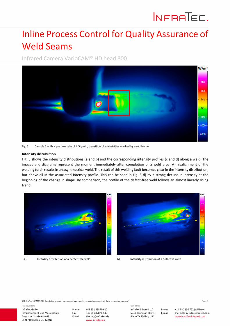
Fig. 2 Sample 2 with a gas flow rate of 4.5 l/min; transition of emissivities marked by a red frame
Intensity distribution
Fig. 3 shows the intensity distributions (a and b) and the corresponding intensity profiles (c and d) along a weld. The
images and diagrams represent the moment immediately after completion of a weld area. A misalignment of the
welding torch results in an asymmetrical weld. The result of this welding fault becomes clear in the intensity distribution,
but above all in the associated intensity profile. This can be seen in Fig. 3 d) by a strong decline in intensity at the
beginning of the change in shape. By comparison, the profile of the defect‐free weld follows an almost linearly rising
trend.
a) Intensity distribution of a defect‐free weld b) Intensity distribution of a defective weld

Inline Process Control for Quality Assurance of Weld Seams Infrared Camera VarioCAM® HD head 800
InfraTec GmbH
Infrarotsensorik und Messtechnik
Gostritzer Straße 61 – 63
01217 Dresden / GERMANY
Phone +49 351 82876‐610
Fax +49 351 82876‐543
E‐mail [email protected]
www.InfraTec.eu
Headquarters
InfraTec infrared LLC
5048 Tennyson Pkwy.
Plano TX 75024 / USA
Phone +1 844‐226‐3722 (toll free)
E‐mail thermo@InfraTec‐infrared.com
www.InfraTec‐infrared.com
USA office
© InfraTec 11/2019 (All the stated product names and trademarks remain in property of their respective owners.) Page 4
c) Intensity profile of a defect‐free weld d) Intensity profile of a defective weld
e) Colour image of a defect‐free weld f) Colour image of a defective weld
Fig. 3 Intensity distribution (a, b), profile (c, d) and colour image of a (e) defect‐free and (f) defective weld. The different scales in the image
sections (c) and (d) should be noted.
Summary
Passive thermography is particularly suitable for the qualitative assessment of processes with high intrinsic heat. Due
to the different emissivities of solid and molten metal, quantification of the weld temperatures is only possible to a
limited extent. For this reason, the relative changes of the radiation are of greater interest in these tests.
The results show that in particular the change in the emissivities as well as the examination of the intensity profile, allow
to obtain reliable information regarding the quality of the weld.


![[List University Name] Quality Assurance Program ... Assurance Foms/University... · [List University Name] Quality Assurance Program Description Document ... Quality Assurance Program](https://img.pdfslide.us/doc/110x75/5ab8c3d37f8b9aa6018d08ac/list-university-name-quality-assurance-program-assurance-fomsuniversitylist.jpg)