Embed Size (px)
Citation preview
17891 Chesterfield Airport Road
Chesterfield, MO 63005
Document Number: AFS-AW139-IBF-ICA
Revision: F
Date: 7 Jan 2013
COPYRIGHT© 2009 Aerospace Filtration Systems, Inc.
UNPUBLISHED — ALL RIGHTS RESERVED
LIMITED and/or RESTRICTED RIGHTS NOTICE
This document, along with its drawings and photographs, contains Trade Secrets and/or Commercial or Financial Information that is proprietary to Aerospace Filtration Systems, Inc. (AFS) under 5 USC 552 as amended, and is Prohibited from Public Disclosure by 18 USC 1905. Do not duplicate or disclose outside the U.S. Government without the express written permission of Aerospace Filtration Systems, Inc. The Government's rights to use, modify, reproduce, release, perform, display, or disclose these technical data are restricted to the purpose of evaluating AFS’s design for FAA commercial certification and airworthiness consideration only. Any reproduction of technical data or portions thereof marked with this legend, or referring to this legend, must also reproduce the markings and legend. Any person, other than the Government, who has been provided access to such data must promptly notify: Aerospace Filtration Systems, Inc., Attn: Business Manager, 17891 Chesterfield Airport Road, Chesterfield, MO 63005
The data subject to this limited/restricted rights notice is contained on all pages.
INSTRUCTIONS FOR CONTINUED AIRWORTHINESS
INLET BARRIER FILTER SYSTEM
Or
INLET FOD SCREEN SYSTEM for the
Agusta S.p.A.
Agusta AB139 and AW139 Series Helicopters
FAA STC No. SR02772CH
AFS-AW139-IBF-ICA Aerospace Filtration Systems, Inc. Revision: F Proprietary Information
Use or disclosure of this material is subject ii AFS Agusta AB139 & AW139 IBF to the restrictions on the title page Instructions for Continued Airworthiness
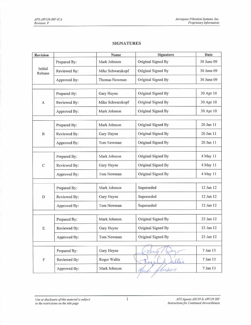
LOG OF REVISIONS
Revision No. Revision Description Release Date
IR Initial Release 30 June 09
A Updated Appendix A 30 Apr 10
B Changed Logo and Address on Cover Sheet 20 Jan 11
C Added information for Icing Protection System (IPS) 4 May 11
D Update due to change in cockpit switch/indicator 12 Jan 12
E Revised electrical schematics in IPB 23 Jan 12
F Added configurations 122000-103, 3G160V03931 and 3G160V04031 7 Jan 13
AFS-AW139-IBF-ICA Aerospace Filtration Systems, Inc. Revision: F Proprietary Information
Use or disclosure of this material is subject iii AFS Agusta AB139 & AW139 IBF to the restrictions on the title page Instructions for Continued Airworthiness
PROPRIETARY DATA STATEMENT
This data, excluding Section 2, Airworthiness Limitations, is proprietary to Aerospace Filtration Systems, Inc. Disclosure, reproduction, or use of this data for any purpose other than helicopter operation and/or maintenance is forbidden without prior written authorization from Aerospace Filtration Systems, Inc.
EFFECTIVITY
Effectivity for this ICA is for all Agusta model AB139 and model AW139 helicopters with the Aerospace Filtration Systems, Inc. (AFS) Inlet Barrier Filter (IBF) Systems serial numbers 13 or later installed.

AFS-AW139-IBF-ICA Aerospace Filtration Systems, Inc. Revision: F Proprietary Information
Use or disclosure of this material is subject iv AFS Agusta AB139 & AW139 IBF to the restrictions on the title page Instructions for Continued Airworthiness
THIS PAGE INTENTIONALLY LEFT BLANK
AFS-AW139-IBF-ICA Aerospace Filtration Systems, Inc. Revision: F Proprietary Information
Use or disclosure of this material is subject v AFS Agusta AB139 & AW139 IBF to the restrictions on the title page Instructions for Continued Airworthiness
INSTRUCTIONS FOR CONTINUED AIRWORTHINESS
For the Aerospace Filtration Systems Engine Inlet Barrier Filter System Installed on the Agusta S.p.A Model AB139 & AW139 Helicopters
TABLE OF CONTENTS
1 INTRODUCTION .............................................................................................................................................. 1
1.1 SCOPE OF THIS MANUAL ........................................................................................................................... 1 1.2 USE OF THIS MANUAL ............................................................................................................................... 1 1.3 DEFINITIONS / TERMINOLOGY ................................................................................................................ 1 1.4 ACRONYMS .................................................................................................................................................. 3 1.5 WARNINGS, CAUTIONS, AND NOTES ..................................................................................................... 3 1.6 UNITS OF MEASURE ................................................................................................................................... 3 1.7 REFERENCE PUBLICATIONS .................................................................................................................... 4 1.8 LIST OF APPLICABLE PUBLICATIONS .................................................................................................... 4 1.9 DISTRIBUTION OF CHANGES ................................................................................................................... 4 1.10 INDICATION OF CHANGES ................................................................................................................... 4 1.11 SYSTEM DESCRIPTION AND OVERVIEW .......................................................................................... 4
2 AIRWORTHINESS LIMITATIONS ............................................................................................................... 7
2.1 GENERAL ...................................................................................................................................................... 8 2.2 FILTER RETIREMENT LIFE ........................................................................................................................ 8 2.3 LIFE LIMITED COMPONENTS ................................................................................................................... 8
3 INSPECTION REQUIREMENTS AND OVERHAUL .................................................................................. 9
3.1 INSPECTION REQUIREMENTS .................................................................................................................. 9 3.1.1 GENERAL REQUIREMENTS ............................................................................................................... 9 3.1.2 FILTER ASSEMBLY INSPECTION ....................................................................................................... 9 3.1.3 STRUCTURAL COMPONENT INSPECTIONS .................................................................................... 9 3.1.4 SYSTEMS AND ELECTRICAL COMPONENT INSPECTIONS .......................................................... 10
3.2 OVERHAUL REQUIREMENTS ................................................................................................................. 12 3.3 SPECIAL INSPECTIONS (CONDITIONAL INSPECTIONS) ................................................................... 12
3.3.1 HARD LANDING ................................................................................................................................. 12 3.3.2 LIGHTNING STRIKE .......................................................................................................................... 13
4 ACCESS PANELS ........................................................................................................................................... 13
4.1 GENERAL DESCRIPTION .......................................................................................................................... 13 4.2 ACCESS FOR MAINTENANCE ................................................................................................................. 13
4.2.1 ACCESS OF FMA AND DP SWITCH ASSEMBLIES .......................................................................... 13 4.2.2 ACCESS OF BYPASS ACTUATOR ASSEMBLY ................................................................................. 13
5 STORAGE ........................................................................................................................................................ 14
6 PLACARDS, DATA PLATES, AND MARKINGS ...................................................................................... 15
6.1 MARKING – PART NUMBER / PMA / SERIALIZATION ........................................................................ 15 6.2 DATA PLATE – FILTER ASSEMBLY........................................................................................................ 15 6.3 PLACARDS / MARKINGS - COCKPIT ...................................................................................................... 15
7 SERVICING ..................................................................................................................................................... 16
7.1 AUTHORIZED MATERIALS ...................................................................................................................... 16 7.2 FILTER SERVICE INTERVALS ................................................................................................................. 16
7.2.1 GENERAL REQUIREMENTS ............................................................................................................. 16 7.2.2 PREPARED FIELD OPERATIONS .................................................................................................... 17 7.2.3 SEVERE ENVIRONMENT OPERATIONS .......................................................................................... 17
7.3 FILTER ASSEMBLY SERVICING ............................................................................................................. 18
AFS-AW139-IBF-ICA Aerospace Filtration Systems, Inc. Revision: F Proprietary Information
Use or disclosure of this material is subject vi AFS Agusta AB139 & AW139 IBF to the restrictions on the title page Instructions for Continued Airworthiness
7.3.1 FILTER PRE-CLEANING ................................................................................................................... 18 7.3.2 FILTER CLEANING ............................................................................................................................ 18 7.3.3 FILTER DRYING ................................................................................................................................. 19 7.3.4 FILTER OILING .................................................................................................................................. 19
7.4 STRUCTURAL COMPONENT SERVICING ............................................................................................. 20 7.5 SYSTEMS AND ELECTRICAL SERVICING ............................................................................................ 21 7.6 AIRCRAFT WASHING ............................................................................................................................... 21
8 TROUBLESHOOTING AND MAINTENANCE ......................................................................................... 21
8.1 MAINTENANCE GENERAL ...................................................................................................................... 21 8.2 COMPONENTS - GENERAL DESCRIPTION ............................................................................................ 22
8.2.1 FILTER ASSY/FILTER SEAL .............................................................................................................. 22 8.2.2 STRUCTURAL ASSEMBLY ................................................................................................................. 22 8.2.3 SYSTEMS AND ELECTRICAL COMPONENTS ................................................................................. 22
8.3 FILTER ASSY / FILTER SEAL ................................................................................................................... 23 8.3.1 FILTER ASSY ....................................................................................................................................... 23 8.3.2 FILTER SEAL ...................................................................................................................................... 27
8.4 STRUCTURAL COMPONENTS ................................................................................................................. 28 8.4.1 UPPER INLET COVER (This section applicable for all IPS equipped aircraft except S/N 41299) .... 28 8.4.2 PLENUM ASSEMBLY ......................................................................................................................... 28 8.4.3 BYPASS MECHANISM ........................................................................................................................ 30 8.4.4 BYPASS DOOR SEAL .......................................................................................................................... 31
8.5 SYSTEMS AND ELECTRICAL COMPONENTS ....................................................................................... 32 8.5.1 CIRCUIT BREAKER............................................................................................................................ 32 8.5.2 COCKPIT INDICATOR LIGHT .......................................................................................................... 32 8.5.3 DIFFERENTIAL PRESSURE SWITCH ............................................................................................... 34 8.5.4 FILTER MAINTENANCE AID ............................................................................................................ 37 8.5.5 ACTUATOR ......................................................................................................................................... 40 8.5.6 WIRING, WIRING HARNESS, CONNECTORS, BACKSHELLS, CIRCUIT BREAKER ..................... 43
8.6 PROTECTIVE TREATMENT ...................................................................................................................... 44 8.7 TROUBLESHOOTING GUIDE ................................................................................................................... 46 8.8 SPECIAL TOOLS / SPECIAL EQUIPMENT .............................................................................................. 47 8.9 CONSUMABLE MATERIALS, SUPPLIES, AND PROTECTIVE TREATMENT SPECIFICATIONS .... 47
9 FOD SCREEN MAINTENANCE ................................................................................................................... 48
9.1 MAINTENANCE GENERAL ...................................................................................................................... 48 9.2 COMPONENTS - GENERAL DESCRIPTION ............................................................................................ 49
9.2.1 FOD SCREEN ASSY ............................................................................................................................ 49 9.2.2 PLENUM ASSEMBLY (STRUCTURAL COMPONENTS) .................................................................. 49 9.2.3 SYSTEMS AND ELECTRICAL COMPONENTS ................................................................................. 49
9.3 FOD SCREEN ASSY .................................................................................................................................... 49 9.3.1 FOD SCREEN ASSY ............................................................................................................................ 49
9.4 STRUCTURAL COMPONENTS ................................................................................................................. 50 9.5 SYSTEMS AND ELECTRICAL COMPONENTS ....................................................................................... 50 9.6 PROTECTIVE TREATMENT ...................................................................................................................... 50 9.7 TROUBLESHOOTING GUIDE ................................................................................................................... 50 9.8 SPECIAL TOOLS / SPECIAL EQUIPMENT .............................................................................................. 50 9.9 CONSUMABLE MATERIALS, SUPPLIES, AND PROTECTIVE TREATMENT SPECIFICATIONS .... 50
10 RECONFIGURATION OF AIRCRAFT FOR IPS AND IBF ..................................................................... 51
10.1 RECONFIGURING FROM IPS TO IBF .................................................................................................. 51 10.2 RECONFIGURING FROM IBF TO IPS .................................................................................................. 51
APPENDIX A .......................................................................................................................................................... A-1
AFS-AW139-IBF-ICA Aerospace Filtration Systems, Inc. Revision: F Proprietary Information
Use or disclosure of this material is subject vii AFS Agusta AB139 & AW139 IBF to the restrictions on the title page Instructions for Continued Airworthiness
TABLE OF FIGURES Figure 1: IBF System and Installation ........................................................................................................................... 6 Figure 2: Filter Maintenance Aid ................................................................................................................................ 11 Figure 3: Filter Maintenance Aid ................................................................................................................................ 11 Figure 4: Component Access ....................................................................................................................................... 14 Figure 5: Example of Filter Assembly Data Plate ....................................................................................................... 15 Figure 6: Oiling Media ................................................................................................................................................ 20 Figure 7: Hand Seamer ................................................................................................................................................ 25 Figure 8: Test Equipment Setup .................................................................................................................................. 36 Figure 9: Test Setup with Manometer ......................................................................................................................... 36 Figure 10: Filter Maintenance Aid Zones .................................................................................................................... 38 Figure 11: Filter Maintenance Aid Reset ..................................................................................................................... 39 Figure 12: Actuator Adjustment .................................................................................................................................. 42 TABLES Table 1 : Inspection Intervals ...................................................................................................................................... 12 Table 2: Protective Treatment for Components ........................................................................................................... 45 Table 3: Troubleshooting Guide .................................................................................................................................. 46 Table 4: Consumable Materials, Supplies and Protective Treatment Specifications ................................................... 47
TABLE OF FIGURES (APPENDIX A)
Figure A-1: IBF System ........................................................................................................................................... A-2 Figure A-2: Major Assemblies ................................................................................................................................. A-3 Figure A-3: Structural Assembly .............................................................................................................................. A-5 Figure A-4: Structural Assembly (Cont.) ................................................................................................................. A-6 Figure A-5: Structural Assembly (Cont.) ................................................................................................................. A-7 Figure A-6: Structural Assembly (Cont.) ................................................................................................................. A-8 Figure A-7: Plenum Assy ....................................................................................................................................... A-11 Figure A-8: Plenum Assembly ............................................................................................................................... A-12 Figure A-9: Fwd Zee Assembly ............................................................................................................................. A-14 Figure A-10: Aft Zee Assembly ............................................................................................................................. A-16 Figure A-11: Support Assembly ............................................................................................................................. A-18 Figure A-12: Closeout Assembly ........................................................................................................................... A-19 Figure A-13: Support Assembly ............................................................................................................................. A-21 Figure A-14: Support Assembly ............................................................................................................................. A-22 Figure A-15: Angle Assembly ................................................................................................................................ A-23 Figure A-16: Fwd Fairing Install ............................................................................................................................ A-24 Figure A-17: Fwd Fairing Assembly ...................................................................................................................... A-26 Figure A-18: Strap Assembly ................................................................................................................................. A-28 Figure A-19: Doubler Assembly ............................................................................................................................ A-29 Figure A-20: Doubler Assembly ............................................................................................................................ A-30 Figure A-21: Strap Assembly ................................................................................................................................. A-31 Figure A-22: Angle Assembly ................................................................................................................................ A-32 Figure A-23: Aft Fairing Install .............................................................................................................................. A-33 Figure A-24: Aft Fairing Assy ................................................................................................................................ A-34 Figure A-25: Doubler Assy .................................................................................................................................... A-35 Figure A-26: Doubler Assy .................................................................................................................................... A-36 Figure A-27: Upr Filter Assy .................................................................................................................................. A-37 Figure A-28: Upr FOD Screen Assy ....................................................................................................................... A-38 Figure A-29: Lwr Filter Assy ................................................................................................................................. A-39
AFS-AW139-IBF-ICA Aerospace Filtration Systems, Inc. Revision: F Proprietary Information
Use or disclosure of this material is subject viii AFS Agusta AB139 & AW139 IBF to the restrictions on the title page Instructions for Continued Airworthiness
Figure A-30: Lwr Screen Assy ............................................................................................................................... A-40 Figure A-31: Aircraft Wiring Schematic (IBF S/N 1-22 & 24) .............................................................................. A-41 Figure A-32: Aircraft Wiring Schematic (IBF S/N 23, 25 and Up) ........................................................................ A-42 Figure A-33: Aircraft Wire Routing ....................................................................................................................... A-43 Figure A-34: Aircraft Wire Routing (Cont.) ........................................................................................................... A-44 Figure A-35: Aircraft Wire Routing (Cont.) ........................................................................................................... A-45 Figure A-36: Aircraft Wire Routing (Cont.) ........................................................................................................... A-46 Figure A-37: Aircraft Wire Routing (Cont.) ........................................................................................................... A-47 Figure A-38: Aircraft Wire Routing (Cont.) ........................................................................................................... A-48 Figure A-39: IBF Indicator/Switch Location .......................................................................................................... A-49 Figure A-40: Circuit Breaker Location ................................................................................................................... A-50 Figure A-41: Indicator/Switch Schematic (LED-42-15-KB-36066) ...................................................................... A-51 Figure A-42: Indicator/Switch Schematic (LED-42-14-KB-SBAFP) .................................................................... A-52 Figure A-43: Actuator Schematic ........................................................................................................................... A-53

AFS-AW139-IBF-ICA Aerospace Filtration Systems, Inc. Revision: F Proprietary Information
Use or disclosure of this material is subject ix AFS Agusta AB139 & AW139 IBF to the restrictions on the title page Instructions for Continued Airworthiness
THIS PAGE INTENTIONALLY LEFT BLANK
AFS-AW139-IBF-ICA Aerospace Filtration Systems, Inc. Revision: F Proprietary Information
Use or disclosure of this material is subject 1 AFS Agusta AB139 & AW139 IBF to the restrictions on the title page Instructions for Continued Airworthiness
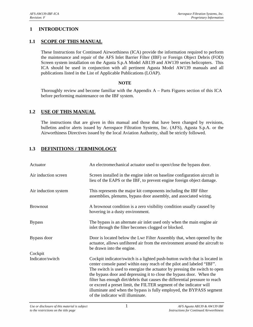
1 INTRODUCTION 1.1 SCOPE OF THIS MANUAL
These Instructions for Continued Airworthiness (ICA) provide the information required to perform the maintenance and repair of the AFS Inlet Barrier Filter (IBF) or Foreign Object Debris (FOD) Screen system installation on the Agusta S.p.A Model AB139 and AW139 series helicopters. This ICA should be used in conjunction with all pertinent Agusta Model AW139 manuals and all publications listed in the List of Applicable Publications (LOAP).
NOTE
Thoroughly review and become familiar with the Appendix A – Parts Figures section of this ICA before performing maintenance on the IBF system.
1.2 USE OF THIS MANUAL
The instructions that are given in this manual and those that have been changed by revisions, bulletins and/or alerts issued by Aerospace Filtration Systems, Inc. (AFS), Agusta S.p.A. or the Airworthiness Directives issued by the local Aviation Authority, shall be strictly followed.
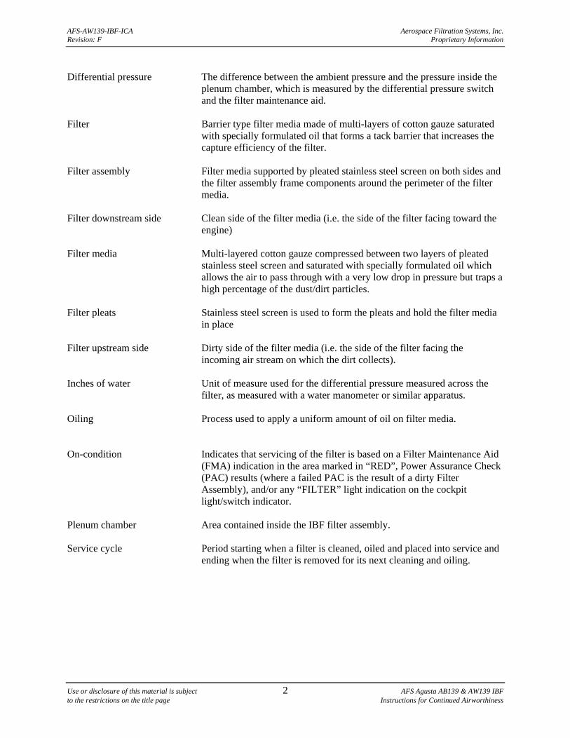
1.3 DEFINITIONS / TERMINOLOGY Actuator An electromechanical actuator used to open/close the bypass door. Air induction screen Screen installed in the engine inlet on baseline configuration aircraft in
lieu of the EAPS or the IBF, to prevent engine foreign object damage. Air induction system This represents the major kit components including the IBF filter
assemblies, plenums, bypass door assembly, and associated wiring. Brownout A brownout condition is a zero visibility condition usually caused by
hovering in a dusty environment. Bypass The bypass is an alternate air inlet used only when the main engine air
inlet through the filter becomes clogged or blocked. Bypass door Door is located below the Lwr Filter Assembly that, when opened by the
actuator, allows unfiltered air from the environment around the aircraft to be drawn into the engine.
Cockpit Indicator/switch Cockpit indicator/switch is a lighted push-button switch that is located in
center console panel within easy reach of the pilot and labeled “IBF”. The switch is used to energize the actuator by pressing the switch to open the bypass door and depressing it to close the bypass door. When the filter has enough dirt/debris that causes the differential pressure to reach or exceed a preset limit, the FILTER segment of the indicator will illuminate and when the bypass is fully employed, the BYPASS segment of the indicator will illuminate.
AFS-AW139-IBF-ICA Aerospace Filtration Systems, Inc. Revision: F Proprietary Information
Use or disclosure of this material is subject 2 AFS Agusta AB139 & AW139 IBF to the restrictions on the title page Instructions for Continued Airworthiness
Differential pressure The difference between the ambient pressure and the pressure inside the
plenum chamber, which is measured by the differential pressure switch and the filter maintenance aid.
Filter Barrier type filter media made of multi-layers of cotton gauze saturated
with specially formulated oil that forms a tack barrier that increases the capture efficiency of the filter.
Filter assembly Filter media supported by pleated stainless steel screen on both sides and
the filter assembly frame components around the perimeter of the filter media.
Filter downstream side Clean side of the filter media (i.e. the side of the filter facing toward the
engine) Filter media Multi-layered cotton gauze compressed between two layers of pleated
stainless steel screen and saturated with specially formulated oil which allows the air to pass through with a very low drop in pressure but traps a high percentage of the dust/dirt particles.
Filter pleats Stainless steel screen is used to form the pleats and hold the filter media
in place Filter upstream side Dirty side of the filter media (i.e. the side of the filter facing the
incoming air stream on which the dirt collects). Inches of water Unit of measure used for the differential pressure measured across the
filter, as measured with a water manometer or similar apparatus. Oiling Process used to apply a uniform amount of oil on filter media. On-condition Indicates that servicing of the filter is based on a Filter Maintenance Aid
(FMA) indication in the area marked in “RED”, Power Assurance Check (PAC) results (where a failed PAC is the result of a dirty Filter Assembly), and/or any “FILTER” light indication on the cockpit light/switch indicator.
Plenum chamber Area contained inside the IBF filter assembly. Service cycle Period starting when a filter is cleaned, oiled and placed into service and
ending when the filter is removed for its next cleaning and oiling.
AFS-AW139-IBF-ICA Aerospace Filtration Systems, Inc. Revision: F Proprietary Information
Use or disclosure of this material is subject 3 AFS Agusta AB139 & AW139 IBF to the restrictions on the title page Instructions for Continued Airworthiness
1.4 ACRONYMS AFS = Aerospace Filtration Systems, Inc. ATA = Air Transport Association of America, Inc. DP = Differential Pressure EAPS = Engine Air Particle Separator FAR = Federal Aviation Regulation FMA = Filter Maintenance Aid FMS = Flight Manual Supplement FOD = Foreign Object Damage IBF = Inlet Barrier Filter ICA = Instructions for Continued Airworthiness IP = Installation Procedures IPB = Illustrated Parts Breakdown LOAP = List of Applicable Publications ITT = Interturbine Temperature OAT = Outside Air Temperature PAC = Power Assurance Check RFM = Rotorcraft Flight Manual SAE = Society of Automotive Engineers TCDS = Type Certificate Data Sheet TIS = Time In Service 1.5 WARNINGS, CAUTIONS, AND NOTES
Warning, cautions and notes are used throughout this manual to emphasize important and critical instructions.
WARNING
AN OPERATING PROCEDURE, PRACTICE, ETC., WHICH, IF NOT CORRECTLY FOLLOWED, COULD RESULT IN PERSONAL INJURY OR LOSS OF LIFE.
CAUTION
AN OPERATING PROCEDURE, PRACTICE, ETC., WHICH, IF NOT STRICTLY OBSERVED, COULD RESULT IN DAMAGE TO OR DESTRUCTION OF EQUIPMENT.
NOTE
An operating procedure, condition, etc., which it is essential to highlight. A note includes supplemental data about the procedure, the practice, the condition, etc
for the maintenance task. 1.6 UNITS OF MEASURE
U.S. Standard units of measure have been used in preparation of this manual. Typical units used in this manual include: inches of water measuring differential pressure, inch-pounds of torque, etc.
AFS-AW139-IBF-ICA Aerospace Filtration Systems, Inc. Revision: F Proprietary Information
Use or disclosure of this material is subject 4 AFS Agusta AB139 & AW139 IBF to the restrictions on the title page Instructions for Continued Airworthiness
1.7 REFERENCE PUBLICATIONS
Reserved for future use. 1.8 LIST OF APPLICABLE PUBLICATIONS
AGUSTA S.p.A AW139 Series Technical Publications FAA FAA Advisory Circular, AC 43.13-1B, Acceptable Methods, Techniques, and Practices – Aircraft Inspection and Repair FAA Advisory Circular, AC 29-1B, Certification of Transport Category Rotorcraft
NOTE
Unless otherwise specified use standard torque values when tightening bolts. (Refer to AC 43.13-1B, Chapter 7)
1.9 DISTRIBUTION OF CHANGES
Changes shall be distributed by posting them on the AFS webpage www.donaldsonaerospace-defense.com. Each customer will be registered and provided access to the webpage via a personalized log-in/password established at the time of kit purchase.
NOTE
This webpage should be checked prior to the performance of any maintenance actions on the IBF system to confirm possession of the latest FAA approved revision. If access to the internet is not possible, contact AFS at (636) 300-5200 for assistance.
1.10 INDICATION OF CHANGES
All changes will be complete revisions with all pages marked with the latest revision letter. All changes since the last revision shall be marked with a black vertical bar in the left side of the page.
1.11 SYSTEM DESCRIPTION AND OVERVIEW
a. The AFS Agusta IBF system, 122000-101 and 122000-103 offers operators the option of either an Inlet Barrier Filter system that includes a plenum assembly, two filter assemblies, a bypass door, fairings, and electrical hardware for each engine or a FOD screen system. The filter assemblies and screen assemblies are interchangeable. The aircraft must have either all filter assemblies or all screen assemblies installed, no mixing of screens and filters is allowed. 3G160V03931 and 3G160V04031 contain the same components as 122000-101 and 122000-103 with the exception of the Upper Inlet Covers and the Electrical Hardware installed on the aircraft.
b. The IBF system is located in the same location and in lieu of the Engine Air Particle Separator
(EAPS). The IBF provides aircraft owner/operators a high performance engine air filtration option that significantly improve filtration efficiency over the EAPS. The IBF will increase the
AFS-AW139-IBF-ICA Aerospace Filtration Systems, Inc. Revision: F Proprietary Information
Use or disclosure of this material is subject 5 AFS Agusta AB139 & AW139 IBF to the restrictions on the title page Instructions for Continued Airworthiness
life of the engine through a dramatic reduction in erosion resulting from the substantial increase in filtration efficiency without degrading engine performance. The AFS IBF system provides dust separation efficiencies exceeding 99% for Society of Automotive Engineers (SAE) AC Coarse and AC Fine dust as defined in specification SAE J726, Air Cleaner Test Code.
c. The IBF system does not interfere with any of the commercial items installed on the Agusta
AB139 and AW139 production aircraft. The IBF is a complete system in which safety, functionality and serviceability were major considerations in the design process. The major kit components include the frame assembly, filter assemblies, cockpit indicator/switch, and bypass system (which includes the bypass door, actuator, differential pressure switch, and filter maintenance aid). Located at the end of this chapter is an exploded view of the major kit components with the exception of the cockpit hardware. For a detailed illustration of all kit components, see the Appendix A - Parts Figures.
d. The major components making up the bypass system include the bypass door, actuator, electrical
wire harness, cockpit indicator/switch, and differential pressure switch. The cockpit indicator/switch energizes the actuator to open and close the bypass doors and the “FILTER” light alerts the pilot that the differential pressure has reached or exceeded its preset limit. In the bypass mode, when the bypass door is fully extended, the “BYPASS” light will illuminate.
e. The IBF system provides a means of monitoring the condition of the filters for each engine both
in-flight and on the ground, and a bypass capability should flow through the filter become restricted. In-flight, a differential pressure switch continuously measures the drop in pressure across the filter, and triggers the cockpit indicator/switch cautioning the pilot any time the differential pressure across the filter reaches or exceeds a preset limit. At this point, the IBF is operating at approximately the same inlet differential pressure normally experienced with the EAPS installed. The electromechanically actuated bypass doors permits unfiltered air to enter the affected engine inlet plenum chamber should the filter media become obstructed, and can be opened or closed as required. On the ground, a Filter Maintenance Aid, mounted aft of the filter assemblies, displays the maximum differential pressure across the filter reached during the last flight. It is accessible only on the ground behind the aft fairing screen, providing the pilot or mechanic the ability to visually gauge the current condition of the filter. This gives the mechanic the ability to forecast the timing of the next service cycle. The Filter Maintenance Aid can be reset by depressing the yellow button marked “PUSH TO RESET” located on the end of the Filter Maintenance Aid (See Figures 2 & 3).
f. The design of the bypass system allows the ground crew to cycle the bypass doors with power on
the aircraft. The light/switch can be pressed to actuate the bypass doors open, and then pressed again to actuate it closed. Full functional verification of the bypass system including all electromechanical components and the filter maintenance aid is possible during routine maintenance (see Chapter 8).
g. Removal of each filter assembly for servicing is easily achieved by loosening bolts and then
removing the filter assemblies from the IBF structure.
h. The FOD screen assemblies are interchangeable with the filter assemblies. Section 9 specifically addresses the FOD screen maintenance requirements.
AFS-AW139-IBF-ICA Aerospace Filtration Systems, Inc. Revision: F Proprietary Information
Use or disclosure of this material is subject 6 AFS Agusta AB139 & AW139 IBF to the restrictions on the title page Instructions for Continued Airworthiness
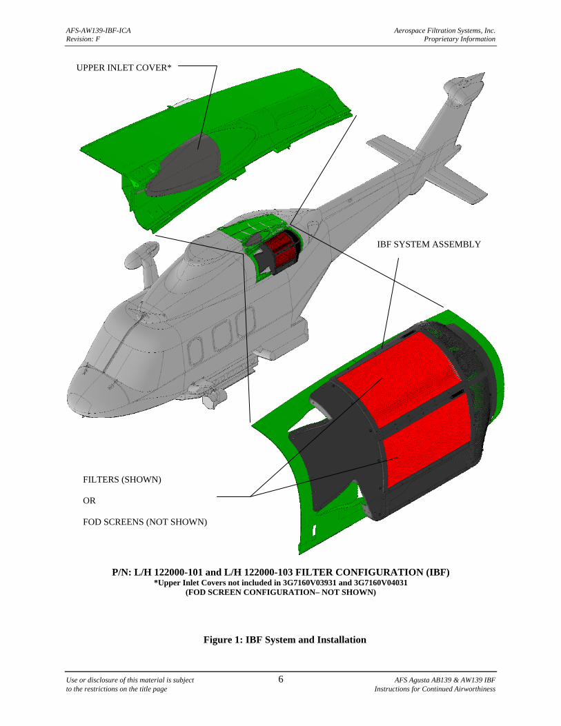
P/N: L/H 122000-101 and L/H 122000-103 FILTER CONFIGURATION (IBF) *Upper Inlet Covers not included in 3G7160V03931 and 3G7160V04031
(FOD SCREEN CONFIGURATION– NOT SHOWN)
Figure 1: IBF System and Installation
UPPER INLET COVER*
FILTERS (SHOWN) OR FOD SCREENS (NOT SHOWN)
IBF SYSTEM ASSEMBLY
AFS-AW139-IBF-ICA Aerospace Filtration Systems, Inc. Revision: F Proprietary Information
Use or disclosure of this material is subject 7 AFS Agusta AB139 & AW139 IBF to the restrictions on the title page Instructions for Continued Airworthiness
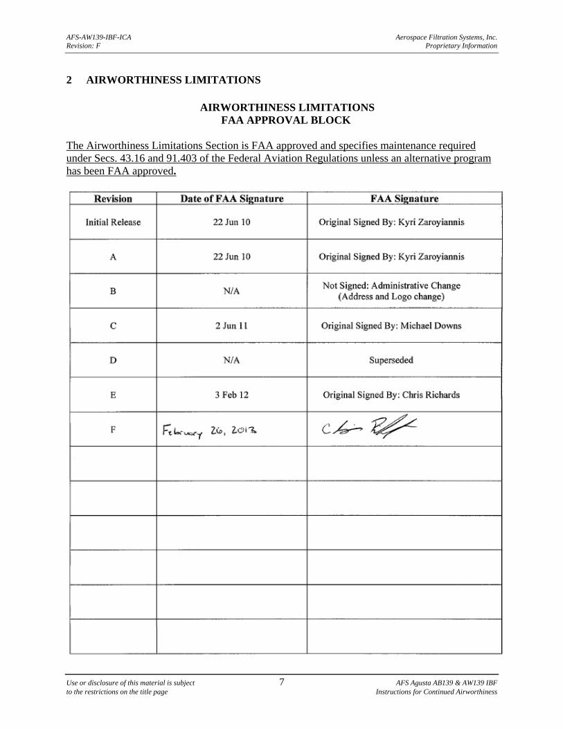
2 AIRWORTHINESS LIMITATIONS
AIRWORTHINESS LIMITATIONS FAA APPROVAL BLOCK
The Airworthiness Limitations Section is FAA approved and specifies maintenance required under Secs. 43.16 and 91.403 of the Federal Aviation Regulations unless an alternative program has been FAA approved.
AFS-AW139-IBF-ICA Aerospace Filtration Systems, Inc. Revision: F Proprietary Information
Use or disclosure of this material is subject 8 AFS Agusta AB139 & AW139 IBF to the restrictions on the title page Instructions for Continued Airworthiness
2.1 GENERAL
The Airworthiness Limitations for the AFS Inlet Barrier Filtration system (IBF) as installed on Agusta S.p.A. model AB139 and AW139 helicopters are FAA approved.
NOTE
The retirement life given or the failure to give a retirement life to a component does not constitute a warranty of any kind. The only warranty applicable to any component is the warranty included in the Purchase Agreement for the helicopter or the component.
2.2 FILTER RETIREMENT LIFE
After fifteen (15) cleaning and oiling cycles, the filters must be removed from service at the next servicing interval. The filter data tag is scribed after each cleaning and oiling cycle (see Section 6.2). When all numerals (1-15) on the data tag have been scribed out, the filters shall be removed from service at the next service interval. No further cleaning cycles are authorized.
2.3 LIFE LIMITED COMPONENTS
The only life limited component features are the number of cleanings of the filter assemblies. See Section 2.2.
AFS-AW139-IBF-ICA Aerospace Filtration Systems, Inc. Revision: F Proprietary Information
Use or disclosure of this material is subject 9 AFS Agusta AB139 & AW139 IBF to the restrictions on the title page Instructions for Continued Airworthiness
3 INSPECTION REQUIREMENTS AND OVERHAUL
3.1 INSPECTION REQUIREMENTS
3.1.1 GENERAL REQUIREMENTS
a. Inspection of the IBF system consists of, in general terms, inspection of the filter assembly, inspection of the structural components, and inspection of electrical and system components. These assembly/component inspection intervals are based on hours after initial installation or on condition as required. The components of the system are divided, generally as a scope of work, into Filter Assembly/Seal, Structural Components, and Systems and Electrical components as is done throughout the manual with Section 9 specific to the FOD screen.
b. Refer to the Appendix A - Parts Figures for component illustrations that provide supplemental
information relative to proper assembly configuration, orientation, and locations for all components to be inspected per Chapter 3 and Table 1. Refer to Appendix A, Figure A-2 for the primary components included in the 122000-101 and 122000-103.
c. Table 1 gives a recommended inspection schedule for the components of the system. The
Trouble-Shooting Guide, Table 3 found near the end of Chapter 8, also gives additional guidance when performing inspections and encountering trouble with the system. Chapter 8 also provides specific inspection guidance and removal/installation procedures for each component and is structured in the same three major groups as discussed above.
3.1.2 FILTER ASSEMBLY INSPECTION
a. The following inspections pertain to the barrier filter assembly and associated components, which include the filter assembly (i.e. filter frame and filter media), and all associated seals/fasteners.
b. ON-CONDITION UP TO TIS LIMIT: Any FMA indication in the “RED”, “FILTER” light
indication of the IBF cockpit indicator/switch light or failed PAC requires a conditional inspection in accordance with Table 1.
c. VISUAL: All filter assembly components (including seals and fasteners) are to be visually
inspected at every annual in accordance with Table 1 checking for the following: filter media for tears, punctures, uneven or damaged pleats; seals for tears/damage; Plenum components for corrosion, cracks, distortions near holes, and check for missing or damaged fasteners.
3.1.3 STRUCTURAL COMPONENT INSPECTIONS
VISUAL: All structural IBF components are to be inspected in accordance with Table 1 every 300 hours/annual. These components include the following: Fore and Aft Frames, Filter Frames, FMA Bracket, Lower Supports, Fairings, Covers, Bypass Doors, and Actuator Supports.
AFS-AW139-IBF-ICA Aerospace Filtration Systems, Inc. Revision: F Proprietary Information
Use or disclosure of this material is subject 10 AFS Agusta AB139 & AW139 IBF to the restrictions on the title page Instructions for Continued Airworthiness
3.1.4 SYSTEMS AND ELECTRICAL COMPONENT INSPECTIONS
a. VISUAL: The systems and electrical components are to be visually inspected in accordance with Table 1 every 300 hours/annual. These components include the following: Wiring, Connectors, Backshells, Circuit Breaker, Cockpit Indicator/switch, Differential Pressure Switch, Filter Maintenance Aid, and Actuator.
b. FUNCTION CHECK: Certain systems and electrical components are also to be function checked
in accordance with Table 1 every annual inspection. These components include the following: Circuit Breaker, Cockpit Indicator/switch, Differential Pressure Switch, Filter Maintenance Aid, and Actuator.
c. FMA CHECK: The FMA check is performed to ascertain the current condition of the filter or to
gage the trend in accumulation of contaminates. The FMA check is only a check of the indicator reading (See Figures 2 & 3). As such it is not considered an inspection of the FMA. The inspection Table 1 does not require a specific “inspection” interval of the FMA. The condition of the Filter Assembly and its accumulation of contaminates will show up as an indication on the FMA. Thus operational environment, more so than time in service, dictate how often the FMA should be checked in order to help determine the next Filter Assembly service requirement. It is an aid in scheduling the Filter Assembly servicing. At any time prior to an FMA indication in the “RED” (See Figure 2), a failed PAC, or a “FILTER” indication on the cockpit indicator/switch, when maintenance or flight personnel see a trend based on the FMA readings over time that would warrant servicing of the filter due to operational considerations, such as when the aircraft will be operated in a remote or off-site location without the ability to readily service the filter, the filter may be serviced, or replaced. See section 7.2 for a further description of the use of the FMA as it relates to the Filter Assembly service interval. See filter servicing Section 7.3.
NOTE
The Filter Maintenance Aid is designed to hold the highest differential pressure across the filter assembly reached during the last flight, and should be reset after servicing of the filter assembly by depressing the yellow button marked “PUSH TO RESET” located on the end of the filter maintenance aid (See Figure 2 & 3).
AFS-AW139-IBF-ICA Aerospace Filtration Systems, Inc. Revision: F Proprietary Information
Use or disclosure of this material is subject 11 AFS Agusta AB139 & AW139 IBF to the restrictions on the title page Instructions for Continued Airworthiness
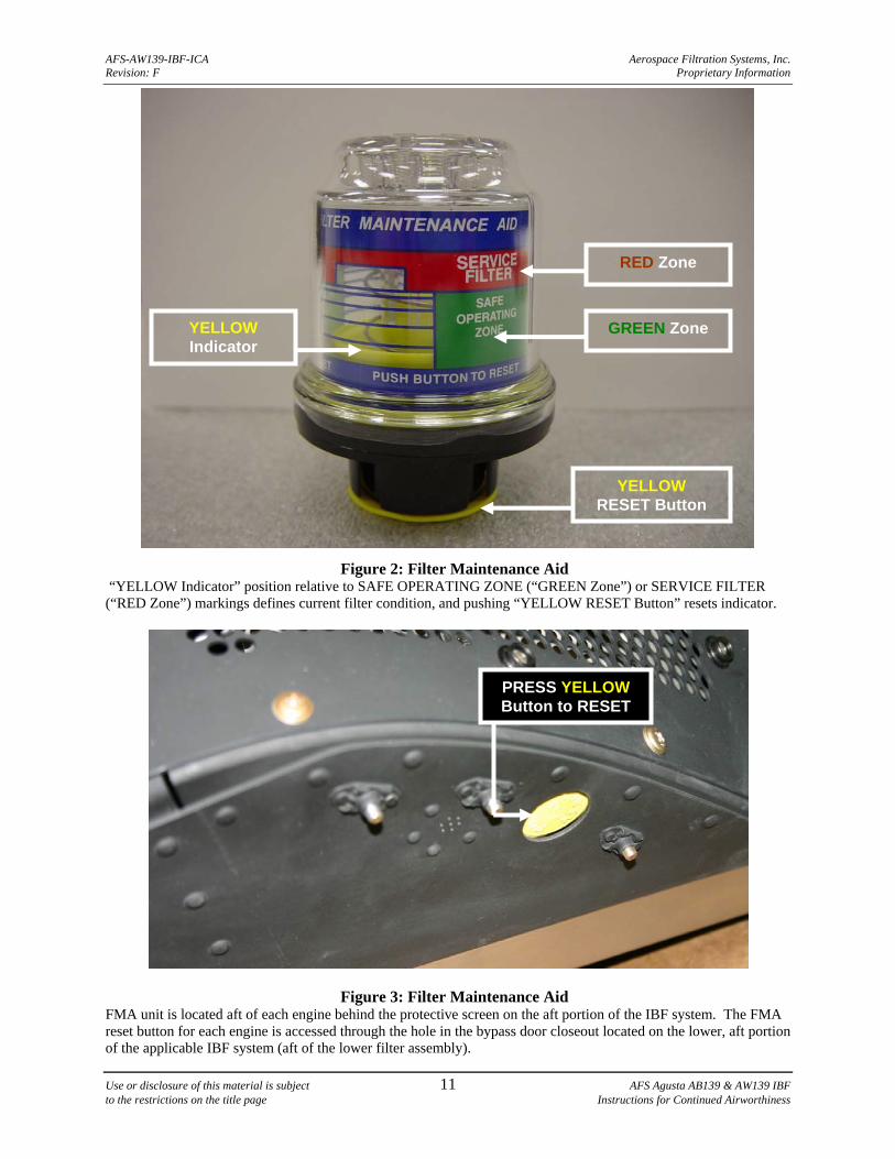
Figure 2: Filter Maintenance Aid
“YELLOW Indicator” position relative to SAFE OPERATING ZONE (“GREEN Zone”) or SERVICE FILTER (“RED Zone”) markings defines current filter condition, and pushing “YELLOW RESET Button” resets indicator.
Figure 3: Filter Maintenance Aid FMA unit is located aft of each engine behind the protective screen on the aft portion of the IBF system. The FMA reset button for each engine is accessed through the hole in the bypass door closeout located on the lower, aft portion of the applicable IBF system (aft of the lower filter assembly).
GREEN Zone
YELLOW RESET Button
RED Zone
YELLOW Indicator
PRESS YELLOW Button to RESET
AFS-AW139-IBF-ICA Aerospace Filtration Systems, Inc. Revision: F Proprietary Information
Use or disclosure of this material is subject 12 AFS Agusta AB139 & AW139 IBF to the restrictions on the title page Instructions for Continued Airworthiness
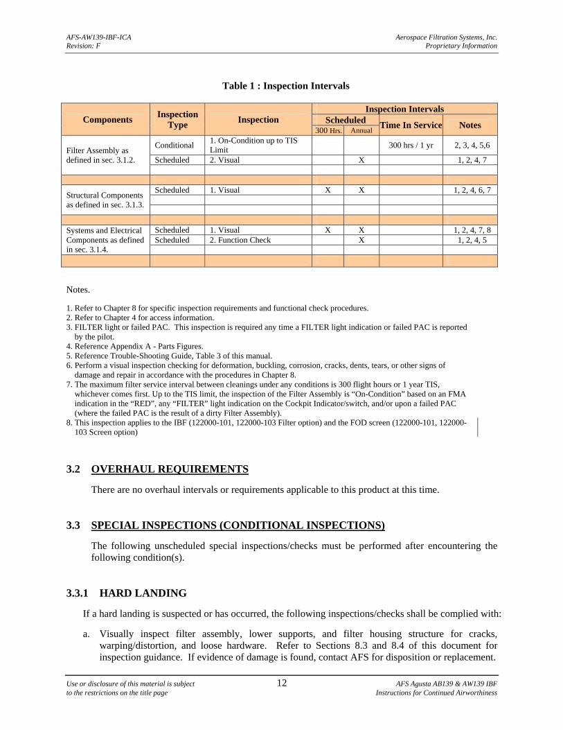
Table 1 : Inspection Intervals
Components Inspection
Type Inspection
Inspection Intervals Scheduled Time In Service Notes
300 Hrs. Annual
Filter Assembly as defined in sec. 3.1.2.
Conditional 1. On-Condition up to TIS Limit
300 hrs / 1 yr 2, 3, 4, 5,6
Scheduled 2. Visual X 1, 2, 4, 7
Structural Components as defined in sec. 3.1.3.
Scheduled 1. Visual X X 1, 2, 4, 6, 7
Systems and Electrical Components as defined in sec. 3.1.4.
Scheduled 1. Visual X X 1, 2, 4, 7, 8 Scheduled 2. Function Check X 1, 2, 4, 5
Notes. 1. Refer to Chapter 8 for specific inspection requirements and functional check procedures. 2. Refer to Chapter 4 for access information. 3. FILTER light or failed PAC. This inspection is required any time a FILTER light indication or failed PAC is reported
by the pilot. 4. Reference Appendix A - Parts Figures. 5. Reference Trouble-Shooting Guide, Table 3 of this manual. 6. Perform a visual inspection checking for deformation, buckling, corrosion, cracks, dents, tears, or other signs of
damage and repair in accordance with the procedures in Chapter 8. 7. The maximum filter service interval between cleanings under any conditions is 300 flight hours or 1 year TIS,
whichever comes first. Up to the TIS limit, the inspection of the Filter Assembly is “On-Condition” based on an FMA indication in the “RED”, any “FILTER” light indication on the Cockpit Indicator/switch, and/or upon a failed PAC (where the failed PAC is the result of a dirty Filter Assembly).
8. This inspection applies to the IBF (122000-101, 122000-103 Filter option) and the FOD screen (122000-101, 122000-103 Screen option)
3.2 OVERHAUL REQUIREMENTS
There are no overhaul intervals or requirements applicable to this product at this time.
3.3 SPECIAL INSPECTIONS (CONDITIONAL INSPECTIONS)
The following unscheduled special inspections/checks must be performed after encountering the following condition(s).
3.3.1 HARD LANDING
If a hard landing is suspected or has occurred, the following inspections/checks shall be complied with:
a. Visually inspect filter assembly, lower supports, and filter housing structure for cracks, warping/distortion, and loose hardware. Refer to Sections 8.3 and 8.4 of this document for inspection guidance. If evidence of damage is found, contact AFS for disposition or replacement.
AFS-AW139-IBF-ICA Aerospace Filtration Systems, Inc. Revision: F Proprietary Information
Use or disclosure of this material is subject 13 AFS Agusta AB139 & AW139 IBF to the restrictions on the title page Instructions for Continued Airworthiness
b. Perform actuator function check to ensure the bypass door is not misaligned and that it operates and seals properly. Refer to Section 8.5 of this document for check/inspection guidance and troubleshooting procedures.
3.3.2 LIGHTNING STRIKE
If a lightning strike is suspected or has occurred, the following inspections/checks shall be complied with:
a. Visually inspect all external surfaces of the filter assembly, lower supports, and filter housing
structure for damage. Refer to Sections 8.3 and 8.4 of this document for inspection guidance. If evidence of damage is found, contact AFS for disposition or replacement.
b. Perform function check of all systems and electrical components. Refer to Section 8.5 of this
document for check/inspection guidance and troubleshooting procedures. 4 ACCESS PANELS 4.1 GENERAL DESCRIPTION
This chapter addresses how to access the IBF system installation for servicing or maintenance. 4.2 ACCESS FOR MAINTENANCE 4.2.1 ACCESS OF FMA AND DP SWITCH ASSEMBLIES
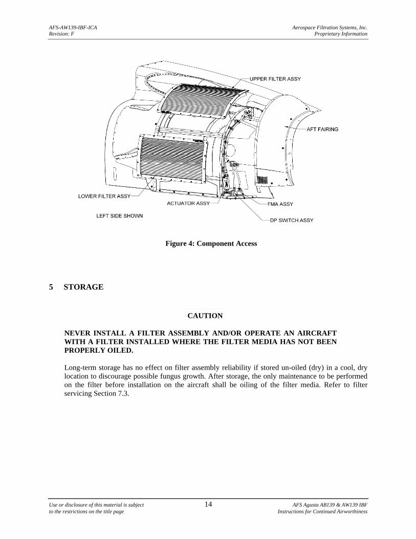
Access for maintenance of the FMA (filter maintenance aid) and the DP (differential pressure) switch and related components (see Figure 4), is accomplished by removing the aft fairing from the applicable engine. See Chapter 8 for component removal/installation procedures, inspection, troubleshooting guide, adjustment/calibration/repair procedures.
4.2.2 ACCESS OF BYPASS ACTUATOR ASSEMBLY
Access for maintenance of the actuator assembly and related components (see Figure 4), is accomplished by removing the Upper and Lower filter assemblies and Aft Fairing. See Chapter 8 for component removal/installation procedures, inspection, troubleshooting guide, adjustment/calibration/repair procedures.
AFS-AW139-IBF-ICA Aerospace Filtration Systems, Inc. Revision: F Proprietary Information
Use or disclosure of this material is subject 14 AFS Agusta AB139 & AW139 IBF to the restrictions on the title page Instructions for Continued Airworthiness
Figure 4: Component Access 5 STORAGE
CAUTION
NEVER INSTALL A FILTER ASSEMBLY AND/OR OPERATE AN AIRCRAFT WITH A FILTER INSTALLED WHERE THE FILTER MEDIA HAS NOT BEEN PROPERLY OILED.
Long-term storage has no effect on filter assembly reliability if stored un-oiled (dry) in a cool, dry location to discourage possible fungus growth. After storage, the only maintenance to be performed on the filter before installation on the aircraft shall be oiling of the filter media. Refer to filter servicing Section 7.3.
AFS-AW139-IBF-ICA Aerospace Filtration Systems, Inc. Revision: F Proprietary Information
Use or disclosure of this material is subject 15 AFS Agusta AB139 & AW139 IBF to the restrictions on the title page Instructions for Continued Airworthiness
6 PLACARDS, DATA PLATES, AND MARKINGS
6.1 MARKING – PART NUMBER / PMA / SERIALIZATION
The IBF system is marked on the Structural assembly to contain the top level part number, the serial number of the system, aircraft eligibility, and the FAA PMA markings. This can be found by removing the lower filter assy and looking inside below the bypass door.
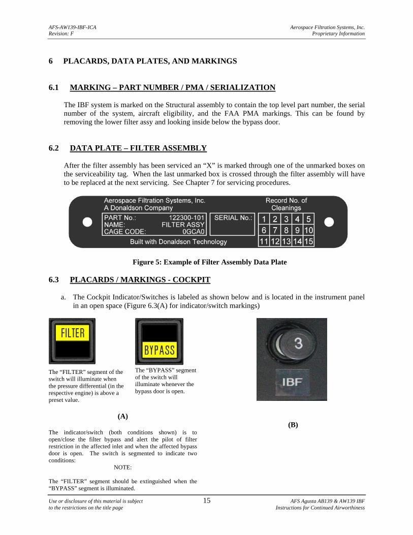
6.2 DATA PLATE – FILTER ASSEMBLY
After the filter assembly has been serviced an “X” is marked through one of the unmarked boxes on the serviceability tag. When the last unmarked box is crossed through the filter assembly will have to be replaced at the next servicing. See Chapter 7 for servicing procedures.
Figure 5: Example of Filter Assembly Data Plate
6.3 PLACARDS / MARKINGS - COCKPIT
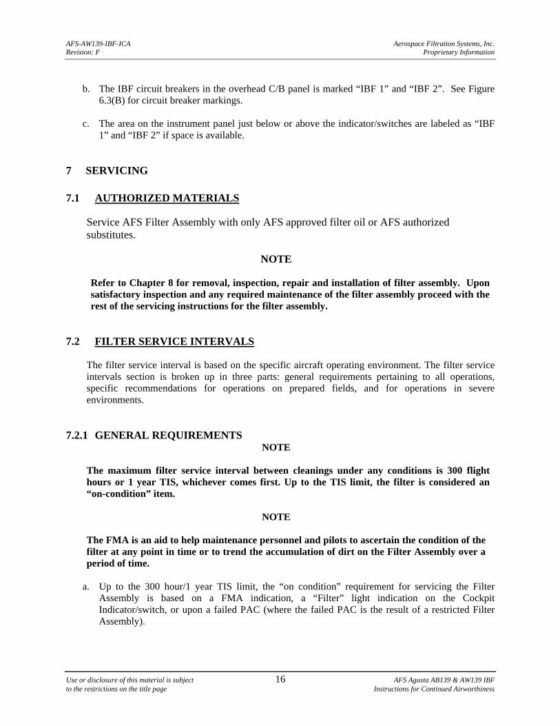
a. The Cockpit Indicator/Switches is labeled as shown below and is located in the instrument panel in an open space (Figure 6.3(A) for indicator/switch markings)
The “FILTER” segment of the switch will illuminate when the pressure differential (in the respective engine) is above a preset value.
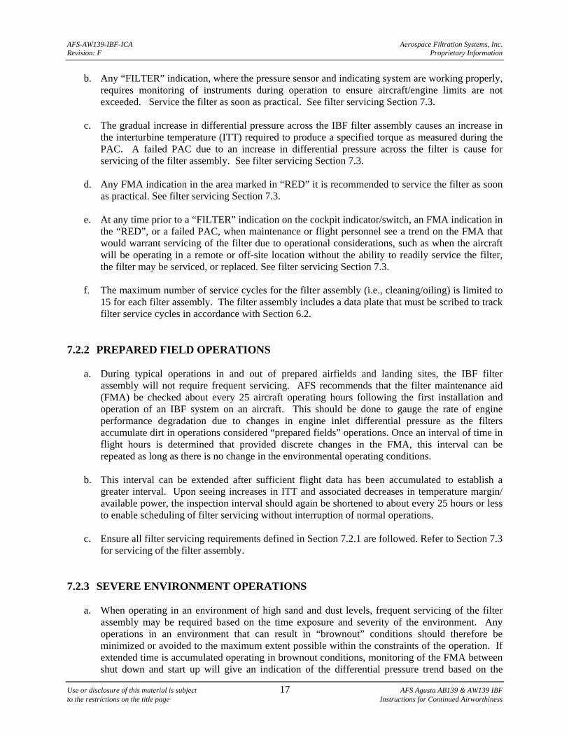
The “BYPASS” segment of the switch will illuminate whenever the bypass door is open.
(A) The indicator/switch (both conditions shown) is to open/close the filter bypass and alert the pilot of filter restriction in the affected inlet and when the affected bypass door is open. The switch is segmented to indicate two conditions:
NOTE: The “FILTER” segment should be extinguished when the “BYPASS” segment is illuminated.
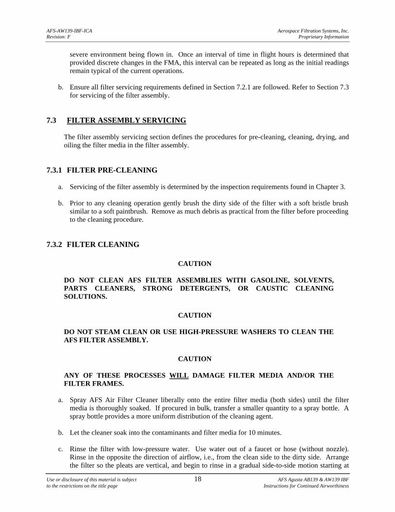
(B)
AFS-AW139-IBF-ICA Aerospace Filtration Systems, Inc. Revision: F Proprietary Information
Use or disclosure of this material is subject 16 AFS Agusta AB139 & AW139 IBF to the restrictions on the title page Instructions for Continued Airworthiness
b. The IBF circuit breakers in the overhead C/B panel is marked “IBF 1” and “IBF 2”. See Figure
6.3(B) for circuit breaker markings. c. The area on the instrument panel just below or above the indicator/switches are labeled as “IBF
1” and “IBF 2” if space is available. 7 SERVICING
7.1 AUTHORIZED MATERIALS
Service AFS Filter Assembly with only AFS approved filter oil or AFS authorized substitutes.
NOTE
Refer to Chapter 8 for removal, inspection, repair and installation of filter assembly. Upon satisfactory inspection and any required maintenance of the filter assembly proceed with the rest of the servicing instructions for the filter assembly.
7.2 FILTER SERVICE INTERVALS
The filter service interval is based on the specific aircraft operating environment. The filter service intervals section is broken up in three parts: general requirements pertaining to all operations, specific recommendations for operations on prepared fields, and for operations in severe environments.
7.2.1 GENERAL REQUIREMENTS
NOTE
The maximum filter service interval between cleanings under any conditions is 300 flight hours or 1 year TIS, whichever comes first. Up to the TIS limit, the filter is considered an “on-condition” item.
NOTE
The FMA is an aid to help maintenance personnel and pilots to ascertain the condition of the filter at any point in time or to trend the accumulation of dirt on the Filter Assembly over a period of time.
a. Up to the 300 hour/1 year TIS limit, the “on condition” requirement for servicing the Filter
Assembly is based on a FMA indication, a “Filter” light indication on the Cockpit Indicator/switch, or upon a failed PAC (where the failed PAC is the result of a restricted Filter Assembly).
AFS-AW139-IBF-ICA Aerospace Filtration Systems, Inc. Revision: F Proprietary Information
Use or disclosure of this material is subject 17 AFS Agusta AB139 & AW139 IBF to the restrictions on the title page Instructions for Continued Airworthiness
b. Any “FILTER” indication, where the pressure sensor and indicating system are working properly, requires monitoring of instruments during operation to ensure aircraft/engine limits are not exceeded. Service the filter as soon as practical. See filter servicing Section 7.3.
c. The gradual increase in differential pressure across the IBF filter assembly causes an increase in
the interturbine temperature (ITT) required to produce a specified torque as measured during the PAC. A failed PAC due to an increase in differential pressure across the filter is cause for servicing of the filter assembly. See filter servicing Section 7.3.
d. Any FMA indication in the area marked in “RED” it is recommended to service the filter as soon
as practical. See filter servicing Section 7.3.
e. At any time prior to a “FILTER” indication on the cockpit indicator/switch, an FMA indication in the “RED”, or a failed PAC, when maintenance or flight personnel see a trend on the FMA that would warrant servicing of the filter due to operational considerations, such as when the aircraft will be operating in a remote or off-site location without the ability to readily service the filter, the filter may be serviced, or replaced. See filter servicing Section 7.3.
f. The maximum number of service cycles for the filter assembly (i.e., cleaning/oiling) is limited to
15 for each filter assembly. The filter assembly includes a data plate that must be scribed to track filter service cycles in accordance with Section 6.2.
7.2.2 PREPARED FIELD OPERATIONS
a. During typical operations in and out of prepared airfields and landing sites, the IBF filter assembly will not require frequent servicing. AFS recommends that the filter maintenance aid (FMA) be checked about every 25 aircraft operating hours following the first installation and operation of an IBF system on an aircraft. This should be done to gauge the rate of engine performance degradation due to changes in engine inlet differential pressure as the filters accumulate dirt in operations considered “prepared fields” operations. Once an interval of time in flight hours is determined that provided discrete changes in the FMA, this interval can be repeated as long as there is no change in the environmental operating conditions.
b. This interval can be extended after sufficient flight data has been accumulated to establish a
greater interval. Upon seeing increases in ITT and associated decreases in temperature margin/ available power, the inspection interval should again be shortened to about every 25 hours or less to enable scheduling of filter servicing without interruption of normal operations.
c. Ensure all filter servicing requirements defined in Section 7.2.1 are followed. Refer to Section 7.3
for servicing of the filter assembly. 7.2.3 SEVERE ENVIRONMENT OPERATIONS
a. When operating in an environment of high sand and dust levels, frequent servicing of the filter assembly may be required based on the time exposure and severity of the environment. Any operations in an environment that can result in “brownout” conditions should therefore be minimized or avoided to the maximum extent possible within the constraints of the operation. If extended time is accumulated operating in brownout conditions, monitoring of the FMA between shut down and start up will give an indication of the differential pressure trend based on the
AFS-AW139-IBF-ICA Aerospace Filtration Systems, Inc. Revision: F Proprietary Information
Use or disclosure of this material is subject 18 AFS Agusta AB139 & AW139 IBF to the restrictions on the title page Instructions for Continued Airworthiness
severe environment being flown in. Once an interval of time in flight hours is determined that provided discrete changes in the FMA, this interval can be repeated as long as the initial readings remain typical of the current operations.
b. Ensure all filter servicing requirements defined in Section 7.2.1 are followed. Refer to Section 7.3
for servicing of the filter assembly.
7.3 FILTER ASSEMBLY SERVICING
The filter assembly servicing section defines the procedures for pre-cleaning, cleaning, drying, and oiling the filter media in the filter assembly.
7.3.1 FILTER PRE-CLEANING
a. Servicing of the filter assembly is determined by the inspection requirements found in Chapter 3. b. Prior to any cleaning operation gently brush the dirty side of the filter with a soft bristle brush
similar to a soft paintbrush. Remove as much debris as practical from the filter before proceeding to the cleaning procedure.
7.3.2 FILTER CLEANING
CAUTION
DO NOT CLEAN AFS FILTER ASSEMBLIES WITH GASOLINE, SOLVENTS, PARTS CLEANERS, STRONG DETERGENTS, OR CAUSTIC CLEANING SOLUTIONS.
CAUTION
DO NOT STEAM CLEAN OR USE HIGH-PRESSURE WASHERS TO CLEAN THE AFS FILTER ASSEMBLY.
CAUTION
ANY OF THESE PROCESSES WILL DAMAGE FILTER MEDIA AND/OR THE FILTER FRAMES.
a. Spray AFS Air Filter Cleaner liberally onto the entire filter media (both sides) until the filter
media is thoroughly soaked. If procured in bulk, transfer a smaller quantity to a spray bottle. A spray bottle provides a more uniform distribution of the cleaning agent.
b. Let the cleaner soak into the contaminants and filter media for 10 minutes.
c. Rinse the filter with low-pressure water. Use water out of a faucet or hose (without nozzle).
Rinse in the opposite the direction of airflow, i.e., from the clean side to the dirty side. Arrange the filter so the pleats are vertical, and begin to rinse in a gradual side-to-side motion starting at
AFS-AW139-IBF-ICA Aerospace Filtration Systems, Inc. Revision: F Proprietary Information
Use or disclosure of this material is subject 19 AFS Agusta AB139 & AW139 IBF to the restrictions on the title page Instructions for Continued Airworthiness
the top and working downward. Adjust the pace to correspond with the cleanliness of the water runoff. As long as the runoff is filled with debris and oil, do not proceed downward.
d. Upon completion, adjust the filter to clean from the dirty side to the clean side, pleats still vertical.
e. Repeat the rinsing procedure once again, until there is no visible debris on the surface and the
runoff water is relatively clean.
f. When finished, flip the filter once again and repeat the rinse from clean side to dirty side.
g. Finally, rotate the filter from top to bottom, and perform the final rinse until the runoff water is free of all debris and oil.
7.3.3 FILTER DRYING
CAUTION
DO NOT USE COMPRESSED AIR TO DRY THE FILTER ASSEMBLY. IT MAY DAMAGE THE FILTER MEDIA.
CAUTION
DO NOT USE HEAT FROM ANY SOURCE TO DRY THE AFS FILTER ASSEMBLY. HEAT MAY SHRINK THE FILTER MEDIA AND MAY DAMAGE THE CORING MATERIAL WITHIN THE FILTER FRAMES.
a. After rinsing, shake off the excess water and let the Filter Assembly dry at room or outside air
temperature (above freezing). b. Ensure dirt or debris does not enter or contact the Filter Assembly while drying.
c. After the Filter Assembly dries, mark the service cycle on data plate in accordance with Section 6.2.
7.3.4 FILTER OILING
CAUTION
NEVER PUT AN AFS FILTER ASSEMBLY IN SERVICE WITHOUT OILING IT.
CAUTION
USE ONLY AN AFS APPROVED OIL.
NOTE
A squeeze bottle capable of accurately measuring out fourteen (14) fluid ounces should be used when applying the oil to the filter as directed below.
AFS-AW139-IBF-ICA Aerospace Filtration Systems, Inc. Revision: F Proprietary Information
Use or disclosure of this material is subject 20 AFS Agusta AB139 & AW139 IBF to the restrictions on the title page Instructions for Continued Airworthiness
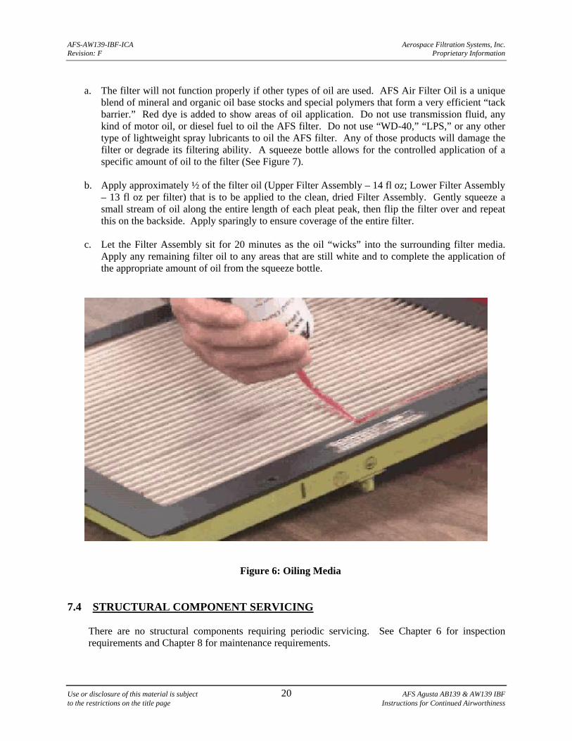
a. The filter will not function properly if other types of oil are used. AFS Air Filter Oil is a unique
blend of mineral and organic oil base stocks and special polymers that form a very efficient “tack barrier.” Red dye is added to show areas of oil application. Do not use transmission fluid, any kind of motor oil, or diesel fuel to oil the AFS filter. Do not use “WD-40,” “LPS,” or any other type of lightweight spray lubricants to oil the AFS filter. Any of those products will damage the filter or degrade its filtering ability. A squeeze bottle allows for the controlled application of a specific amount of oil to the filter (See Figure 7).
b. Apply approximately ½ of the filter oil (Upper Filter Assembly – 14 fl oz; Lower Filter Assembly
– 13 fl oz per filter) that is to be applied to the clean, dried Filter Assembly. Gently squeeze a small stream of oil along the entire length of each pleat peak, then flip the filter over and repeat this on the backside. Apply sparingly to ensure coverage of the entire filter.
c. Let the Filter Assembly sit for 20 minutes as the oil “wicks” into the surrounding filter media.
Apply any remaining filter oil to any areas that are still white and to complete the application of the appropriate amount of oil from the squeeze bottle.
Figure 6: Oiling Media
7.4 STRUCTURAL COMPONENT SERVICING
There are no structural components requiring periodic servicing. See Chapter 6 for inspection requirements and Chapter 8 for maintenance requirements.
AFS-AW139-IBF-ICA Aerospace Filtration Systems, Inc. Revision: F Proprietary Information
Use or disclosure of this material is subject 21 AFS Agusta AB139 & AW139 IBF to the restrictions on the title page Instructions for Continued Airworthiness
7.5 SYSTEMS AND ELECTRICAL SERVICING
There are no system and electrical components requiring periodic servicing. See Chapter 6 for inspection requirements and Chapter 8 for maintenance requirements.
NOTE
The Filter Maintenance Aid is designed to hold the highest differential pressure across the filter assembly reached during the last flight, and should be reset after servicing of the filter assembly by depressing the yellow button marked “PUSH TO RESET” located on the end of the filter maintenance aid (See Figure 10).
7.6 AIRCRAFT WASHING
During aircraft washing the IBF system, including the filter assemblies, should be protected or removed to avoid damaging the filter media with high pressure spray nozzles or to prevent solvents rinsing away the oil in the filter media.
8 TROUBLESHOOTING AND MAINTENANCE
8.1 MAINTENANCE GENERAL
CAUTION
THOROUGHLY REVIEW AND BECOME FAMILIAR WITH THE APPENDIX A - PARTS FIGURES BEFORE PERFORMING MAINTENANCE ON THE IBF SYSTEM.
NOTE
Except where otherwise indicated, all torque values shall be in accordance with Agusta Maintenance Manual or Chapter 7 of FAA Advisory Circular AC 43.13-1B.
a. The components of the system are divided, generally as a scope of work, into Structural
Assembly (consisting of Forward, Aft, Upper, and Lower Frame Assemblies and Bypass Assembly), Fairing Assemblies, Filter Assemblies, and Systems and Electrical components throughout the manual. Refer to Appendix A, Figures A-1 thru A-41. Table 1 gives a recommended inspection schedule for the components of the system. The troubleshooting guide in Table 3 provides additional guidance for performing inspections when encountering trouble with the system.
b. The maintenance chapter is organized by removal, inspection, troubleshooting, adjustment,
calibration and/or repair, and installation for the major components noted above, as applicable to the particular component. For some components a functional check is included. Not all components will require adjustment, or calibration, or have any approved functional check or
AFS-AW139-IBF-ICA Aerospace Filtration Systems, Inc. Revision: F Proprietary Information
Use or disclosure of this material is subject 22 AFS Agusta AB139 & AW139 IBF to the restrictions on the title page Instructions for Continued Airworthiness
repair procedures. Contact AFS for possible repairs when not listed in this manual. In some cases defective components will require replacement.
c. In general, visually inspect all structural components for oversized or elongated holes,
deformation, cracks, corrosion, missing fasteners or components, fretting, galling, etc. Any component exhibiting these conditions requires repair or replacement.
d. In general, visually inspect fasteners for damaged or missing threads, in both the bolt or screw
and the nut or nut plate. If a self-locking fastener can be fully threaded by hand, replace the self-locking fastener.
e. In general, visually inspect all electrical connections for security, corrosion, arcing, breakdown of
insulation, and overheating. Repair or replace components exhibiting defects. Inspect and repair components per Agusta technical manuals or AC 43.13-1B, Chapter 11.
8.2 COMPONENTS - GENERAL DESCRIPTION 8.2.1 FILTER ASSY/FILTER SEAL (Refer to Appendix A, Figures A-2, A-27, A-29)
a. Filter Assembly - The Filter Assembly is composed of the filter media (stainless steel mesh covering cotton gauze) bonded into the aluminum alloy filter frame assembly.
b. Seal - The Seal is expanded foam with Dacron backing affixed to the Filter Assembly.
8.2.2 STRUCTURAL ASSEMBLY (Refer to Appendix A, Figures A-2 thru, A-26)
a. Upper Inlet Cover – This part is a stainless steel cover that closes of the upper inlet.
b. Plenum Assembly – This assembly is the aluminum structure where the bypass door, upper filter assembly and lower filter assembly are located. The forward fairing gets attached to the forward frame of the plenum assy and the aft fairing gets attached to the aft frame of plenum assy. The filter assemblies, bypass mechanism, actuator, differential pressure switch, and filter maintenance aid assembly are secured to this assembly.
8.2.3 SYSTEMS AND ELECTRICAL COMPONENTS (Refer to Appendix A, Figures A-31 thru A-41)
a. Cockpit Indicator/Switch - Each cockpit indicator/switch provides the lighting/switching function for the applicable bypass door for each engine. The cockpit indicator light illuminates when the differential pressure between ambient and the plenum chamber has reached its preset limit. The construction details of the component do not warrant field maintenance. Repair or servicing of this component requires the component to be sent back to AFS for disposition.
b. Differential Pressure Switch - Each Differential Pressure Switch provides a signal to the
applicable Cockpit Indicator/Switch for annunciation of the “FILTER” light to signal the differential pressure across the Filter Assembly(s) has reached a preset limit. The construction
AFS-AW139-IBF-ICA Aerospace Filtration Systems, Inc. Revision: F Proprietary Information
Use or disclosure of this material is subject 23 AFS Agusta AB139 & AW139 IBF to the restrictions on the title page Instructions for Continued Airworthiness
details of the component do not warrant field maintenance. Repair of this component requires the component to be sent back to AFS for disposition.
c. Filter Maintenance Aid - The Filter Maintenance Aid provides an indication to maintenance
personnel as to the trend of the differential pressure across the applicable Filter Assembly(s). The construction details of the component do not warrant field maintenance. Repair of this component requires it to be sent back to AFS for disposition, or replaced. The FMA is an aid to help maintenance personnel and pilots to ascertain the current condition or trend in accumulation of dirt on the Filter Assembly.
d. Actuator - The Actuator provides mechanical actuation of the Bypass Door should the pilot
depress the applicable cockpit indicator/switch. The construction details of the component do not warrant field maintenance. Repair of this component requires the component to be sent back to AFS for disposition or replaced.
e. Wiring, Connectors, Backshells, Circuit Breaker – The wiring utilizes wire per Military
Specification Mil-W-22759/41. The gauge and marking identification is specified on the wiring diagram. The connectors, backshells, and circuit breaker are military specification components, or where applicable, vendor designed components. The construction details of these components (other than wiring) do not warrant field maintenance.
8.3 FILTER ASSY / FILTER SEAL (Refer to Appendix A, Figures A-2, A-27, A-29) 8.3.1 FILTER ASSY 8.3.1.1 REMOVAL – FILTER ASSY
CAUTION
UPON REMOVAL OF ANY FILTER ASSEMBLY COVER THE ENGINE INLET (AS SOON AS THERE IS ACCESS TO THE INLET), TO PREVENT FOREIGN OBJECT DAMAGE (FOD).
a. Obtain required equipment to safely access and perform maintenance on the filters (i.e. ladder, lift
scaffolding, etc.) b. To remove filters – Loosen the eighteen (18) captive bolts that retain each Filter Assembly to the
Plenum Assembly. (Refer to Appendix A, Figures A-2, A-27, A-29)
c. Use a plastic scraper to gently break any seal between the plenum structure and the seal itself. The filter assembly must be carefully removed so as not to damage the filter seal.
d. Repeat steps b and c for all filters being removed.
AFS-AW139-IBF-ICA Aerospace Filtration Systems, Inc. Revision: F Proprietary Information
Use or disclosure of this material is subject 24 AFS Agusta AB139 & AW139 IBF to the restrictions on the title page Instructions for Continued Airworthiness
8.3.1.2 INSPECTION – FILTER ASSY
NOTE
After servicing of the Filter Assembly or at any time the Filter Assembly is inspected, the pleats may require straightening or crimping. If you cannot see the bottom of the pleat, the airflow will be restricted and/or the pleats will adhere to one another when dirt loaded. Any restriction to the flow through the pleats will result in increased differential pressure and reduction in dirt loading capacity. In order to insure ideal flow characteristics through the filter media, the pleats must be straightened or crimped with a hand seamer.
a. Visually inspect the pleats on both sides of the filter. If you cannot see the bottom of the pleat,
when sighting the length, or depth of the pleat, straightening of the pleat is required. Refer to “Adjustment” for pleat straightening procedures.
b. If this inspection is in response to a FILTER light indication or failed PAC, perform
troubleshooting per Table 3. If troubleshooting indicates a dirty filter, service filter per Section 7.3.
c. Inspect the filter assembly frame for cracks, gouges, distortion or deformation, corrosion, loose or
missing fasteners, and missing or deteriorated protective coating. Refer to “Repair” for criteria / disposition.
d. Inspect the filter seal. Refer to “Filter Seal” procedures. 8.3.1.3 ADJUSTMENT - FILTER
CAUTION
HAND SEAMER MUST BE LIMITED TO A MAXIMUM JAW DEPTH OF 1 1/4 INCH. A DEEPER JAW DEPTH CAN RESULT IN DEFORMATION OR DAMAGE TO THE ADJOINING PLEATS.
CAUTION
DO NOT OVER CRIMP AND CRUSH PLEAT; CARE MUST BE TAKEN TO SQUEEZE THE PLEATS WITHOUT DAMAGING THE PLEATED SCREEN. THE RADIUS AT THE TOP OF THE PLEAT SHOULD REMAIN INTACT, NOT CREASED.
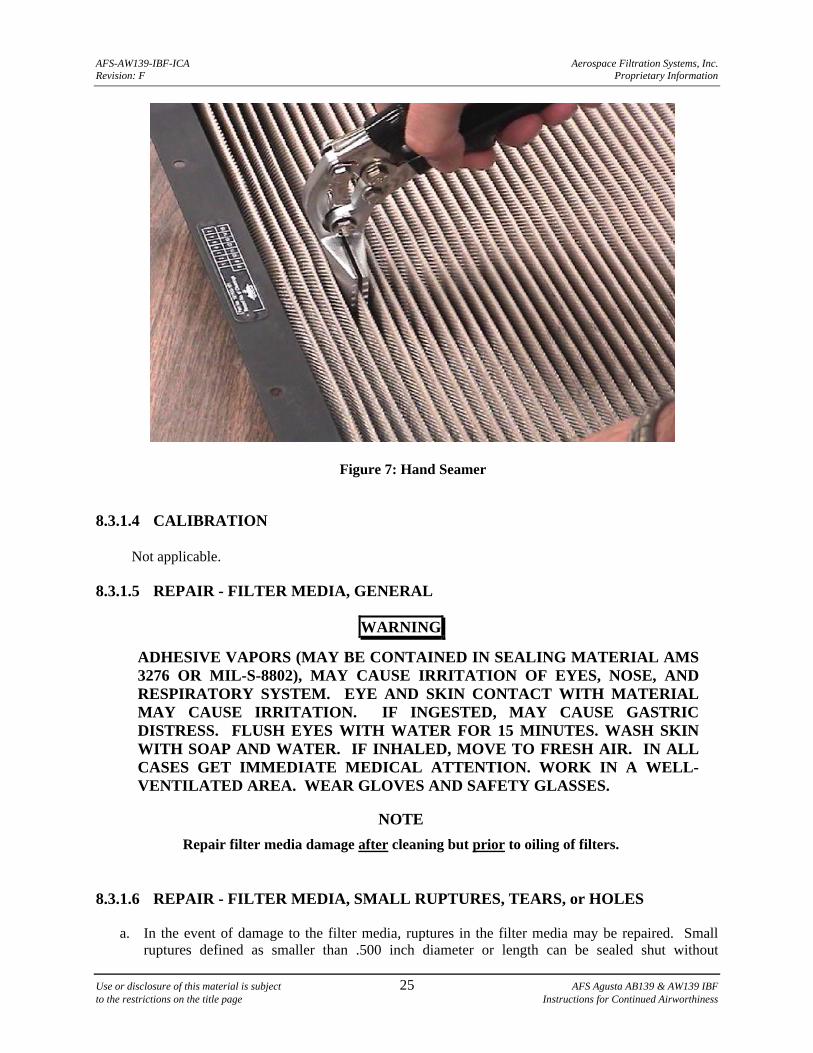
a. If you cannot see the bottom of a pleat, use a hand seamer (See Special Tools/Special Equipment,
Section 8.8.a.) to crimp the pleat and to straighten the pleat. Sight down the length and depth of the pleat to confirm the pleat is straightened (See Figure 7).
b. Once one side is crimped, flip the filter over and crimp the other side as required following the
guidance above. Use caution not to crush the pleats when straightening them. Use care to maintain the original radius, as much as possible, at the top of the pleat.
AFS-AW139-IBF-ICA Aerospace Filtration Systems, Inc. Revision: F Proprietary Information
Use or disclosure of this material is subject 25 AFS Agusta AB139 & AW139 IBF to the restrictions on the title page Instructions for Continued Airworthiness
Figure 7: Hand Seamer 8.3.1.4 CALIBRATION
Not applicable. 8.3.1.5 REPAIR - FILTER MEDIA, GENERAL
WARNING
ADHESIVE VAPORS (MAY BE CONTAINED IN SEALING MATERIAL AMS 3276 OR MIL-S-8802), MAY CAUSE IRRITATION OF EYES, NOSE, AND RESPIRATORY SYSTEM. EYE AND SKIN CONTACT WITH MATERIAL MAY CAUSE IRRITATION. IF INGESTED, MAY CAUSE GASTRIC DISTRESS. FLUSH EYES WITH WATER FOR 15 MINUTES. WASH SKIN WITH SOAP AND WATER. IF INHALED, MOVE TO FRESH AIR. IN ALL CASES GET IMMEDIATE MEDICAL ATTENTION. WORK IN A WELL-VENTILATED AREA. WEAR GLOVES AND SAFETY GLASSES.
NOTE
Repair filter media damage after cleaning but prior to oiling of filters. 8.3.1.6 REPAIR - FILTER MEDIA, SMALL RUPTURES, TEARS, or HOLES
a. In the event of damage to the filter media, ruptures in the filter media may be repaired. Small ruptures defined as smaller than .500 inch diameter or length can be sealed shut without
AFS-AW139-IBF-ICA Aerospace Filtration Systems, Inc. Revision: F Proprietary Information
Use or disclosure of this material is subject 26 AFS Agusta AB139 & AW139 IBF to the restrictions on the title page Instructions for Continued Airworthiness
degradation of performance to the filter assembly. Each filter assembly may have up to 3 small ruptures that may be repaired, but no repair may be within 1” of an adjacent repair.
b. Prior to performing any of these repairs, the filter material must be cleaned of contamination and
oil. Refer to Chapter 7 for cleaning of the filter assembly. Perform the repair to a cleaned and dry filter assembly. Each time the entire filter assembly is cleaned, repaired, and oiled, a mark shall be scribed on the filter assembly data plate in accordance with Section 6.2 indicating a cleaning cycle was performed.
c. Trim ruptures, tears, or holes in the filter media up to .500 inches in length or diameter to remove
loose material (wire or cotton gauze).
d. Seal the affected area using two-part sealant, AMS 3276 or MIL-S-8802. Allow the sealant to bleed into the filter material and cure. Follow manufacturer’s directions for proper mixing, application, and curing of the two-part sealant.
e. Proceed with oiling the filter. Refer to Chapter 7.
8.3.1.7 REPAIR - FILTER MEDIA, LARGE RUPTURES, TEARS, or HOLES
Larger ruptures exceeding .500 inch in size are not repairable in the field. Contact AFS for disposition and possible repair procedures, or discard the filter assembly.
8.3.1.8 REPAIR – FILTER ASSY, OTHER DAMAGE
a. The repair procedures defined above are for damage resulting in ruptures, tears, or holes in the filter media. The following is for field repairable damage to the filter assembly frame. Field repairable damage to the filter assembly frame is limited to blending of scratches and gouges, and / or the re-application of protective coatings. See Table 2 for application of protective coatings.
b. Any damage to the filter frames such as cracking requires the filter assembly to be returned to
AFS for evaluation and disposition, or replacement. Any damage to the filter frames such as warping or distortion (to the extent that a good seal of the filter frame, when installed and/or torqued, do not permit the filter assembly to sit flush against the forward, aft, and/or the upper frame assembly) requires the filter assembly be returned to AFS for evaluation and disposition, or be replaced.
8.3.1.10 INSTALLATION
a. Locate and place the filter on the plenum assembly, aligning the captive bolts with the nutplates in the plenum assembly. (Refer to Appendix A, Figures A-27 and A-29)
b. Tighten the eighteen (18) captive bolts that retain each Filter Assembly to the Plenum Assembly.
AFS-AW139-IBF-ICA Aerospace Filtration Systems, Inc. Revision: F Proprietary Information
Use or disclosure of this material is subject 27 AFS Agusta AB139 & AW139 IBF to the restrictions on the title page Instructions for Continued Airworthiness
8.3.2 FILTER SEAL 8.3.2.1 REMOVAL
a. Gain access to the filter seal by removing the filter assembly(s). Refer to Section 8.3.1.1. b. Carefully remove the seal by peeling it away from the filter assembly(s) (See Appendix A,
Figures A-27 and A-29). Use a plastic scraper or other suitable tool that is softer than aluminum to peel the seal from the filter assembly(s). Discard the removed seal.
8.3.2.2 INSPECTION
Inspect the filter seal for any tears, nicks, gouges, missing pieces or a permanent set or flattening of the seal. If the seal exhibits any of these conditions, repair or replace the seal.
8.3.2.3 REPAIR
WARNING
ADHESIVE VAPORS (IN SEALANT SUCH AS RTV 736) MAY CAUSE IRRITATION OF EYES, NOSE, AND RESPIRATORY SYSTEM. EYE AND SKIN CONTACT WITH MATERIAL MAY CAUSE IRRITATION. IF INGESTED, MAY CAUSE GASTRIC DISTRESS. FLUSH EYES WITH WATER FOR 15 MINUTES. WASH SKIN WITH SOAP AND WATER. IF INHALED, MOVE TO FRESH AIR. IN ALL CASES GET IMMEDIATE MEDICAL ATTENTION. WORK IN A WELL-VENTILATED AREA. WEAR GLOVES AND SAFETY GLASSES.
a. Small tears, nicks, or gouges in the seal may be repaired using RTV 736 Sealant. Use a wooden
tongue depressor, cotton swab, or similar tool to dab a small amount of sealant on the damage to repair tears, nicks, or gouges in the seal. Smooth over sealant to create a smooth flush repair similar to the original seal cross section. Allow to dry before re-installing filter. If the repair does not allow the filter assembly(s) from sealing to the forward, aft, and/or upper frame assembly replace the seal.
b. If the Seal exhibits extensive tears, deep nicks or gouges, or missing pieces that would prevent the
filter from properly sealing, replace the seal. 8.3.2.4 INSTALLATION
a. Gain access to the filter seal. Refer to filter assembly removal and filter seal removal. b. To install the seal, apply RTV 736 sealant to the foam side of the seal. Locate and apply the seal
to the clean dry surface on the filter frame and press in place.
AFS-AW139-IBF-ICA Aerospace Filtration Systems, Inc. Revision: F Proprietary Information
Use or disclosure of this material is subject 28 AFS Agusta AB139 & AW139 IBF to the restrictions on the title page Instructions for Continued Airworthiness
8.4 STRUCTURAL COMPONENTS
CAUTION
DURING ANY MAINTENANCE OPERATION, IF THE REMOVAL OF ANY FILTER ASSEMBLY IS REQUIRED, COVER THE ENGINE INLET (AS SOON AS THERE IS ACCESS TO THE INLET), TO PREVENT FOREIGN OBJECT DAMAGE (FOD).
8.4.1 UPPER INLET COVER (This section applicable for all IPS equipped aircraft except
S/N 41299) 8.4.1.1 REMOVAL OF UPPER INLET COVER
a. Remove the
8.4.2 PLENUM ASSEMBLY
(Refer to Appendix A, Figures A-2 thru A-15) 8.4.2.1 REMOVAL OF PLENUM ASSEMBLY
b. Remove the upper and lower filter assemblies. (See Sections 8.3.1.1) c. Remove the forward and aft fairings.
d. Disconnect electrical connector from inside the engine door.
e. Remove the hardware securing the electrical connector to the engine door. f. Cut the seal between the bottom edge of the plenum assembly and the engine door.
g. Remove the nineteen (19) NAS6203-4H bolts that secure the plenum assembly to the engine
door.
h. Remove plenum assembly from aircraft. 8.4.2.2 INSPECTION
a. The Plenum Assembly interfaces with the surrounding aircraft structure. See Appendix A, Figures A-3 thru A-15. At these locations inspect for chafing or fretting, elongation of fastener holes, damage to nut plates and fasteners, corrosion, cracking, and deformation.
b. Inspection for the above conditions and any other conditions that may be applicable are defined in
the Agusta Helicopter technical manuals.
c. Inspections of the major components that make up the Plenum Assembly are to be inspected at this time for the following:
AFS-AW139-IBF-ICA Aerospace Filtration Systems, Inc. Revision: F Proprietary Information
Use or disclosure of this material is subject 29 AFS Agusta AB139 & AW139 IBF to the restrictions on the title page Instructions for Continued Airworthiness
d. Cracking. Visually inspect the assemblies for cracking using a 10x magnification glass at the corners, radiuses, and transitions in part thickness. Inspect suspect areas carefully using the 10x magnification. No cracks are allowed in the assemblies. If cracks are found, Plenum Assembly must be replaced.
e. Warping or distortion. Visually inspect the assemblies for warping or distortion. Any warping or
distortion that keeps the Filter Assemblies from creating a seal to the Plenum Assemblies requires disposition instructions from AFS or replacement.
f. Protective Coatings. Visually inspect the assemblies for missing, damaged, or “scratched
through” protective coatings. Re-apply protective coatings per Table 2 of this chapter.
g. Corrosion. Visually inspect the assemblies for corrosion in accordance with AC 43.13-1B, Chapter 6 and Table 2.
h. Missing, damaged or loose associated components. Visually inspect the assemblies for missing
damaged or loose components. 8.4.2.3 TROUBLESHOOTING/ADJUSTMENT/CALIBRATION
Not applicable. Contact AFS for disposition of defective component or replace. 8.4.2.4 REPAIR
a. Cracks. No cracks are allowed in any part of the Plenum Assembly. Cracks are not repairable. If cracks exist, the Plenum Assembly must be replaced.
b. Warping or distortion. Visually inspect the Plenum Assembly for warping or distortion. Any
warping or distortion that keeps the Filter Assemblies from creating a seal to the frames requires disposition instructions from AFS or replacement.
c. Protective Coatings. Re-apply protective coatings per Table 2 of this chapter.
d. Corrosion. Treat corrosion in accordance with AC 43.13-1B, Chapter 6 and Table 2.
e. Missing, damaged or loose associated components. Replace missing or damaged components.
Secure loose components. 8.4.2.5 INSTALLATION
a. Place the Plenum Assembly on the engine door (R/H or L/H) of the aircraft. b. Install nineteen (19) NAS6203-4H bolts into the Plenum Assembly and secure to the engine door.
c. Safety wire all bolts per NASM33540.
d. Seal the entire periphery where the plenum assy mates with the engine door using MIL-S-8802.
Blend and fay sealant to ensure an airtight seal. e. Install electrical connector in engine door using four (4) MS35206-215 screws, eight (8)
NAS1149CN432R washers and four (4) MS21042L04 nuts.
AFS-AW139-IBF-ICA Aerospace Filtration Systems, Inc. Revision: F Proprietary Information
Use or disclosure of this material is subject 30 AFS Agusta AB139 & AW139 IBF to the restrictions on the title page Instructions for Continued Airworthiness
f. Connect IBF System electrical disconnect located on the inside of the engine door. g. Install the Forward and Aft Fairings. h. Install the Upper and Lower Filter Assemblies. (See Sections 8.3.1.5)
8.4.3 BYPASS MECHANISM (Refer to Appendix A, Figures A-3) 8.4.3.1 REMOVAL
a. Remove the Upper and Lower Filter Assemblies (See Section 8.3.1.1). b. Remove the Aft Fairing.
c. Remove the Actuator.
d. Remove the Bellcrank (122122-201) by removing the MS20392-2R21 Pin and MS24665-65 Cotter Pin and sliding the Bellcrank off the Bypass Door.
e. Remove the Bypass Door by sliding the Bypass Door aft and rotating the forward edge of the Bypass Door inboard.
8.4.3.2 INSPECTION
a. Cracking. Visually inspect the Bypass Mechanism and related parts for cracking using 10x magnification glass at the corners, radiuses, and transitions in part thickness. Inspect suspect areas carefully using the 10x magnification. No cracks are allowed in the Bypass Mechanism. If cracks are found, component must be replaced.
b. Warping or distortion. Visually inspect the Bypass Mechanism for warping or distortion. Any
warping or distortion that keeps the IBF System from being installed and secured properly requires disposition instructions from AFS or replacement of the Bypass Mechanism component.
c. Protective Coatings. Visually inspect the Bypass Mechanism for missing, damaged, or
“scratched through” protective coatings. Re-apply protective coatings per Table 2 of this chapter.
d. Corrosion. Visually inspect the Bypass Mechanism and related parts for corrosion in accordance with AC 43.13-1B, Chapter 6, and Table 2.
e. Missing, damaged or loose associated components. Visually inspect for missing, damaged, or
loose components. 8.4.3.3 TROUBLESHOOTING/ADJUSTMENT/CALIBRATION
Not applicable. Contact AFS for disposition of defective component or replace. 8.4.3.4 REPAIR
AFS-AW139-IBF-ICA Aerospace Filtration Systems, Inc. Revision: F Proprietary Information
Use or disclosure of this material is subject 31 AFS Agusta AB139 & AW139 IBF to the restrictions on the title page Instructions for Continued Airworthiness
a. Cracks. No cracks are allowed in the Bypass Mechanism. Cracks are not repairable. If cracks exist, Bypass Mechanism component must be replaced.
b. Warping or distortion. Visually inspect the Bypass Mechanism for warping or distortion. Any
warping or distortion that keeps the IBF System from being installed and secured properly requires disposition instructions from AFS or replacement of the Bypass Mechanism component.
c. Protective Coatings. Visually inspect the Bypass Mechanism for missing, damaged, or
“scratched through” protective coatings. Re-apply protective coatings per Table 2 of this chapter.
d. Corrosion. Treat corrosion in accordance with AC 43.13-1B, Chapter 6 and Table 2.
e. Missing, damaged or loose associated components. Replace missing or damaged components. Secure loose components.
8.4.3.5 INSTALLATION
a. Insert the forward end of the Bypass Door 122120-201 into the bushing in the Forward Zee. b. Close the Bypass Door Assy against the seal.
c. Insert the Bellcrank 122122-201 through the bushing in the Aft Zee onto the Bypass Door Assy
shaft.
d. Insert Pin MS20392-2R21 through the Bellcrank and Bypass Door Assy.
e. Locate washer NAS1149C0316J over the Pin.
f. Insert Cotter Pin MS24665-69 through Pin and secure.
g. Connect Actuator IAW section 8.5.5.8
8.4.4 BYPASS DOOR SEAL (Refer to Appendix A, Figures A-7) 8.4.4.1 REMOVAL
a. Gain access to the bypass door seal by removing the bypass mechanism. Refer to Section 8.4.2.1.
b. Carefully remove the seal by peeling it away from the structural assembly (See Appendix A, Figures A-7). Use a plastic scraper or other suitable tool that is softer than aluminum to peel the seal from the structural assembly. Discard the removed seal.
8.4.4.2 INSPECTION
Inspect the filter seal for any tears, nicks, gouges, missing pieces or a permanent set or flattening of the seal. If the seal exhibits any of these conditions, replace the seal.
AFS-AW139-IBF-ICA Aerospace Filtration Systems, Inc. Revision: F Proprietary Information
Use or disclosure of this material is subject 32 AFS Agusta AB139 & AW139 IBF to the restrictions on the title page Instructions for Continued Airworthiness
8.4.4.3 INSTALLATION
a. Gain access to the area behind the bypass opening. Refer to Section 8.4.2.1. b. To install the seal, apply RTV 736 sealant to the foam side of the seal. Locate and apply the seal
to the clean dry surface on the backside of the bypass opening in the structural assembly and press in place.
8.5 SYSTEMS AND ELECTRICAL COMPONENTS 8.5.1 CIRCUIT BREAKER
8.5.1.1 REMOVAL
a. Gain access to the back of the overhead circuit breaker panel. b. Remove terminal connectors at back of circuit breaker.
c. Remove nut from circuit breaker face.
d. Remove circuit breaker from panel.
e. Tag and secure wiring.
8.5.1.2 INSPECTION
a. Inspect circuit breaker for proper functioning. Refer to Table 3 for troubleshooting. b. Inspect circuit breaker for security, damage, overheating, or corrosion. If component is suspect,
replace defective component or contact AFS for disposition. 8.5.1.3 TROUBLESHOOTING
See Table 3 for troubleshooting guide. 8.5.1.4 ADJUSTMENT / CALIBRATION / REPAIR
Not applicable. Contact AFS for disposition of defective component or replace. 8.5.1.5 INSTALLATION
a. Place circuit breaker into panel opening in correct orientation. b. Secure circuit breaker to circuit breaker panel with nut.
c. Secure terminal connectors at rear of circuit breaker.
8.5.2 COCKPIT INDICATOR LIGHT
(Refer to Appendix A, Figures A-38 and A-40)
AFS-AW139-IBF-ICA Aerospace Filtration Systems, Inc. Revision: F Proprietary Information
Use or disclosure of this material is subject 33 AFS Agusta AB139 & AW139 IBF to the restrictions on the title page Instructions for Continued Airworthiness
8.5.2.1 REMOVAL
a. Gain access to the back of the instrument panel. b. Remove Quik-Connect plug at back of Indicator/Switch.
c. Remove mounting sleeve from back of Indicator/Switch.
d. Slide Indicator/Switch out of panel.
e. Tag and secure wiring.
8.5.2.2 INSPECTION
a. Inspect Cockpit Indicator/Switch for proper functioning. Refer to Section 8.5.2.5 and to Table 3 for troubleshooting.
b. Inspect Cockpit Indicator/Switch for security, damage, overheating, corrosion, or distortion.
Replace defective component or contact AFS for disposition. 8.5.2.3 TROUBLESHOOTING
See Table 3 for troubleshooting guide. 8.5.2.4 ADJUSTMENT / CALIBRATION / REPAIR
Not applicable. Contact AFS for disposition of defective component or replace. 8.5.2.5 FUNCTION CHECK
CAUTION
THIS PROCEDURE INTRODUCES THE POSSIBILITY OF ENGINE FOD.
a. Verify the Bypass Door is closed and aircraft electric power is ON. b. Perform Differential Pressure Switch function check (Ref 8.5.3.5).
c. Verify Cockpit Indicator/Switch “FILTER” amber light illuminates. d. Depress Cockpit Indicator/Switch to open the Bypass Door.
e. Verify the Bypass Door is open and “BYPASS” light illuminates.
f. Depress Cockpit Indicator/Switch to close the Bypass Door.
g. Verify the Bypass Door is closed and “BYPASS” light extinguishes and if no longer
needed, that aircraft electric power is OFF.
AFS-AW139-IBF-ICA Aerospace Filtration Systems, Inc. Revision: F Proprietary Information
Use or disclosure of this material is subject 34 AFS Agusta AB139 & AW139 IBF to the restrictions on the title page Instructions for Continued Airworthiness
8.5.2.6 INSTALLATION
a. Slide Cockpit Indicator/Switch into panel opening. b. Secure Indicator/Switch to panel with mounting sleeve.
c. Attach Quik-Connect plug at rear of Cockpit Indicator/Switch.
d. Perform Cockpit Indicator/Switch Function Check.
8.5.3 DIFFERENTIAL PRESSURE SWITCH
(Refer to Appendix A, Figures A-6) 8.5.3.1 REMOVAL
a. Remove aft fairing to access the Differential Pressure Switch. b. Remove hoses, fittings, and attaching hardware from the Differential Pressure Switch. c. Disconnect and secure connector.
d. Loosen clamp and remove Differential Pressure Switch.
8.5.3.2 INSPECTION
a. Inspect for general serviceability, damage, corrosion, and missing components. Inspect the attaching hardware for security.
b. Inspect the Tube Assembly for debris and insure that the tube is clear and unobstructed.
8.5.3.3 TROUBLESHOOTING
See Table 3 for troubleshooting guidance. 8.5.3.4 ADJUSTMENT / CALIBRATION / REPAIR
The construction details of the component do not warrant field maintenance. Repair of this component requires the component to be sent back to AFS for disposition.
8.5.3.5 FUNCTION CHECK
CAUTION
THIS PROCEDURE INTRODUCES THE POSSIBILITY OF ENGINE FOD.
CAUTION
IMPROPER USE OF THE ALTIMETER TEST SET COULD RESULT IN DAMAGE TO THE SWITCH CALIBRATION.
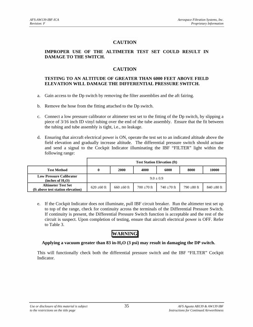
AFS-AW139-IBF-ICA Aerospace Filtration Systems, Inc. Revision: F Proprietary Information
Use or disclosure of this material is subject 35 AFS Agusta AB139 & AW139 IBF to the restrictions on the title page Instructions for Continued Airworthiness
CAUTION
IMPROPER USE OF THE ALTIMETER TEST SET COULD RESULT IN DAMAGE TO THE SWITCH.
CAUTION
TESTING TO AN ALTITUDE OF GREATER THAN 6000 FEET ABOVE FIELD ELEVATION WILL DAMAGE THE DIFFERENTIAL PRESSURE SWITCH.
a. Gain access to the Dp switch by removing the filter assemblies and the aft fairing. b. Remove the hose from the fitting attached to the Dp switch. c. Connect a low pressure calibrator or altimeter test set to the fitting of the Dp switch, by slipping a
piece of 3/16 inch ID vinyl tubing over the end of the tube assembly. Ensure that the fit between the tubing and tube assembly is tight, i.e., no leakage.
d. Ensuring that aircraft electrical power is ON, operate the test set to an indicated altitude above the
field elevation and gradually increase altitude. The differential pressure switch should actuate and send a signal to the Cockpit Indicator illuminating the IBF “FILTER” light within the following range:
Test Station Elevation (ft)
Test Method 0 2000 4000 6000 8000 10000
Low Pressure Calibrator (inches of H2O)
9.0 ± 0.9
Altimeter Test Set (ft above test station elevation)
620 ±60 ft 660 ±60 ft 700 ±70 ft 740 ±70 ft 790 ±80 ft 840 ±80 ft
e. If the Cockpit Indicator does not illuminate, pull IBF circuit breaker. Run the altimeter test set up
to top of the range, check for continuity across the terminals of the Differential Pressure Switch. If continuity is present, the Differential Pressure Switch function is acceptable and the rest of the circuit is suspect. Upon completion of testing, ensure that aircraft electrical power is OFF. Refer to Table 3.
WARNING
Applying a vacuum greater than 83 in-H2O (3 psi) may result in damaging the DP switch.
This will functionally check both the differential pressure switch and the IBF “FILTER” Cockpit Indicator.
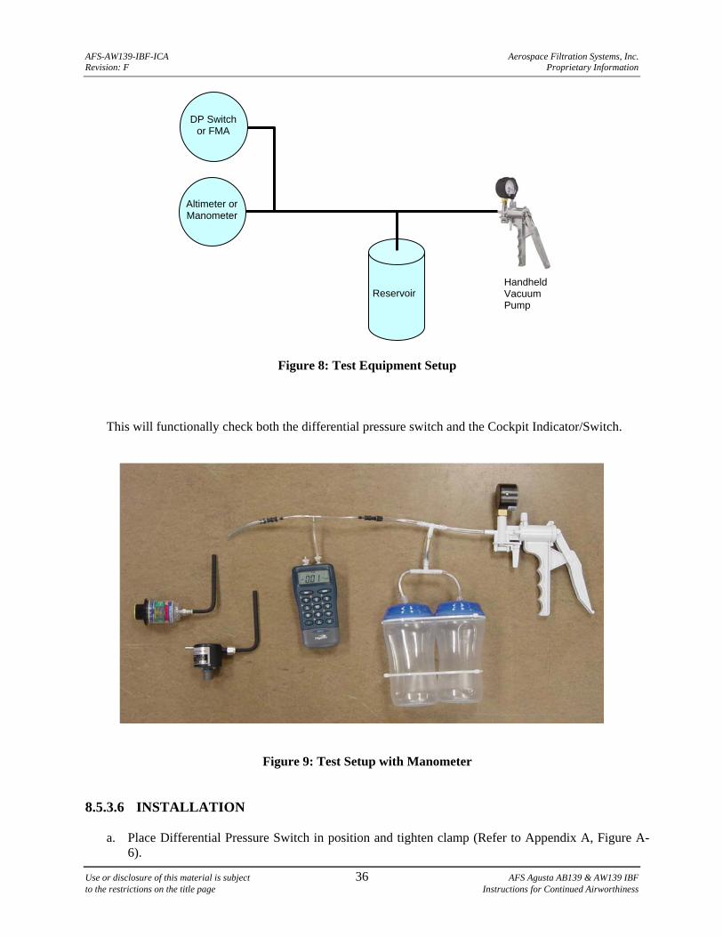
AFS-AW139-IBF-ICA Aerospace Filtration Systems, Inc. Revision: F Proprietary Information
Use or disclosure of this material is subject 36 AFS Agusta AB139 & AW139 IBF to the restrictions on the title page Instructions for Continued Airworthiness
Figure 8: Test Equipment Setup
This will functionally check both the differential pressure switch and the Cockpit Indicator/Switch.
Figure 9: Test Setup with Manometer
8.5.3.6 INSTALLATION
a. Place Differential Pressure Switch in position and tighten clamp (Refer to Appendix A, Figure A-6).
Altimeter or Manometer
DP Switch or FMA
Reservoir Handheld Vacuum Pump
AFS-AW139-IBF-ICA Aerospace Filtration Systems, Inc. Revision: F Proprietary Information
Use or disclosure of this material is subject 37 AFS Agusta AB139 & AW139 IBF to the restrictions on the title page Instructions for Continued Airworthiness
b. Attach hoses, fittings, and attaching hardware.
c. Connect and secure connector.
d. Perform Function Check of Differential Pressure Switch and Indicator/Switch (Refer to Sections
8.5.2.5 and 8.5.3.5).
e. Install the aft fairing. 8.5.4 FILTER MAINTENANCE AID
(Refer to Appendix A, Figure A-6) 8.5.4.1 REMOVAL
a. Remove aft fairing to access the Filter Maintenance Aid. b. Disconnect Tube Assembly from Filter Maintenance Aid. (Appendix A, Figure 6)
c. Remove hardware and FMA Retaining Ring from Filter Maintenance Aid Mount.
d. Remove Filter Maintenance Aid.
8.5.4.2 INSPECTION
a. Inspect the Filter Maintenance Aid and associated mounting for discoloration affecting readability, cracks, deformation, missing or damaged components, and serviceability.
b. Inspect the Filter Maintenance Aid Tube Assembly for debris and insure that the tube is clear and
unobstructed.
c. Inspect the associated components, such as the Mount Assembly and hardware for missing components, cracks, distortion or deformation, scratches or gouges, or missing protective coatings. If Filter Maintenance Aid Bracket assembly is cracked or nut-plates are unserviceable, drill out the attaching rivets that secure the component and obtain new component and re-attach using same type rivets (MS20470AD4 for bracket) or (MS1097AD3 for nut-plates).
8.5.4.3 TROUBLESHOOTING
See Troubleshooting Guide, Table 3. 8.5.4.4 ADJUSTMENT / CALIBRATION / REPAIR
The construction details of the component do not warrant field maintenance. Repair of this component requires the component to be sent back to AFS for disposition, or replaced.
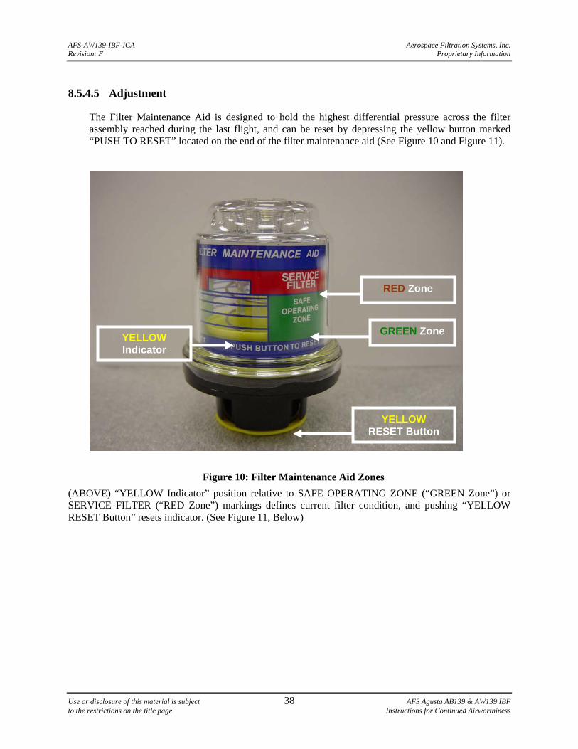
AFS-AW139-IBF-ICA Aerospace Filtration Systems, Inc. Revision: F Proprietary Information
Use or disclosure of this material is subject 38 AFS Agusta AB139 & AW139 IBF to the restrictions on the title page Instructions for Continued Airworthiness
8.5.4.5 Adjustment
The Filter Maintenance Aid is designed to hold the highest differential pressure across the filter assembly reached during the last flight, and can be reset by depressing the yellow button marked “PUSH TO RESET” located on the end of the filter maintenance aid (See Figure 10 and Figure 11).
Figure 10: Filter Maintenance Aid Zones
(ABOVE) “YELLOW Indicator” position relative to SAFE OPERATING ZONE (“GREEN Zone”) or SERVICE FILTER (“RED Zone”) markings defines current filter condition, and pushing “YELLOW RESET Button” resets indicator. (See Figure 11, Below)
GREEN Zone
YELLOW RESET Button
RED Zone
YELLOW Indicator
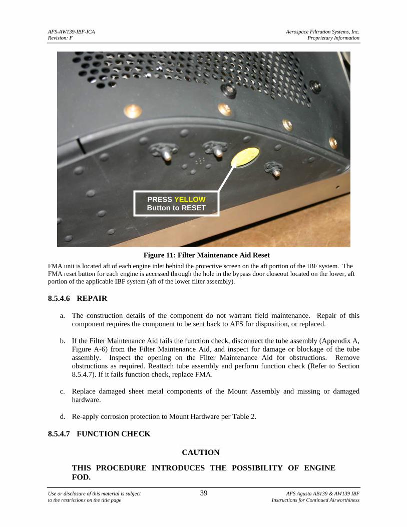
AFS-AW139-IBF-ICA Aerospace Filtration Systems, Inc. Revision: F Proprietary Information
Use or disclosure of this material is subject 39 AFS Agusta AB139 & AW139 IBF to the restrictions on the title page Instructions for Continued Airworthiness
Figure 11: Filter Maintenance Aid Reset
FMA unit is located aft of each engine inlet behind the protective screen on the aft portion of the IBF system. The FMA reset button for each engine is accessed through the hole in the bypass door closeout located on the lower, aft portion of the applicable IBF system (aft of the lower filter assembly). 8.5.4.6 REPAIR
a. The construction details of the component do not warrant field maintenance. Repair of this component requires the component to be sent back to AFS for disposition, or replaced.
b. If the Filter Maintenance Aid fails the function check, disconnect the tube assembly (Appendix A,
Figure A-6) from the Filter Maintenance Aid, and inspect for damage or blockage of the tube assembly. Inspect the opening on the Filter Maintenance Aid for obstructions. Remove obstructions as required. Reattach tube assembly and perform function check (Refer to Section 8.5.4.7). If it fails function check, replace FMA.
c. Replace damaged sheet metal components of the Mount Assembly and missing or damaged
hardware.
d. Re-apply corrosion protection to Mount Hardware per Table 2. 8.5.4.7 FUNCTION CHECK
CAUTION
THIS PROCEDURE INTRODUCES THE POSSIBILITY OF ENGINE FOD.
PRESS YELLOW Button to RESET
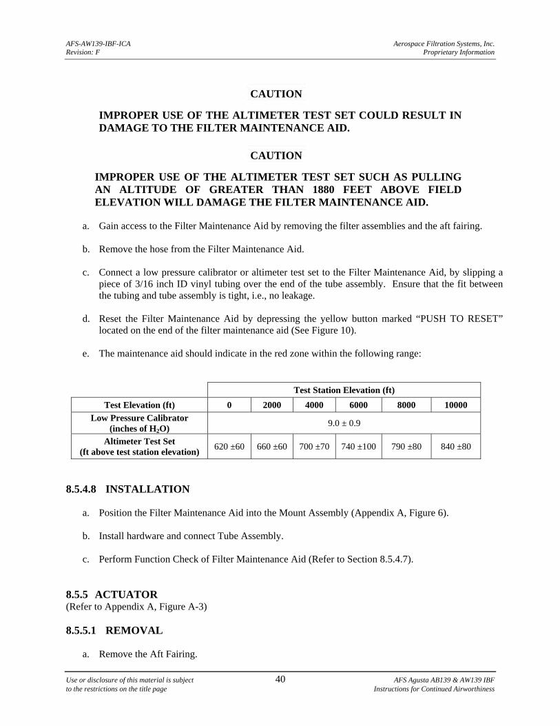
AFS-AW139-IBF-ICA Aerospace Filtration Systems, Inc. Revision: F Proprietary Information
Use or disclosure of this material is subject 40 AFS Agusta AB139 & AW139 IBF to the restrictions on the title page Instructions for Continued Airworthiness
CAUTION
IMPROPER USE OF THE ALTIMETER TEST SET COULD RESULT IN DAMAGE TO THE FILTER MAINTENANCE AID.
CAUTION
IMPROPER USE OF THE ALTIMETER TEST SET SUCH AS PULLING AN ALTITUDE OF GREATER THAN 1880 FEET ABOVE FIELD ELEVATION WILL DAMAGE THE FILTER MAINTENANCE AID.
a. Gain access to the Filter Maintenance Aid by removing the filter assemblies and the aft fairing.
b. Remove the hose from the Filter Maintenance Aid. c. Connect a low pressure calibrator or altimeter test set to the Filter Maintenance Aid, by slipping a
piece of 3/16 inch ID vinyl tubing over the end of the tube assembly. Ensure that the fit between the tubing and tube assembly is tight, i.e., no leakage.
d. Reset the Filter Maintenance Aid by depressing the yellow button marked “PUSH TO RESET”
located on the end of the filter maintenance aid (See Figure 10).
e. The maintenance aid should indicate in the red zone within the following range:
Test Station Elevation (ft)
Test Elevation (ft) 0 2000 4000 6000 8000 10000
Low Pressure Calibrator (inches of H2O)
9.0 ± 0.9
Altimeter Test Set (ft above test station elevation)
620 ±60 660 ±60 700 ±70 740 ±100 790 ±80 840 ±80
8.5.4.8 INSTALLATION
a. Position the Filter Maintenance Aid into the Mount Assembly (Appendix A, Figure 6).
b. Install hardware and connect Tube Assembly.
c. Perform Function Check of Filter Maintenance Aid (Refer to Section 8.5.4.7).
8.5.5 ACTUATOR (Refer to Appendix A, Figure A-3) 8.5.5.1 REMOVAL
a. Remove the Aft Fairing.
AFS-AW139-IBF-ICA Aerospace Filtration Systems, Inc. Revision: F Proprietary Information
Use or disclosure of this material is subject 41 AFS Agusta AB139 & AW139 IBF to the restrictions on the title page Instructions for Continued Airworthiness
b. Disconnect and secure electrical connector at Actuator.
c. Remove the Upper Attachment Hardware securing the Actuator at the top.
d. Remove the Lower Attachment Hardware securing the Actuator to the Bellcrank.
e. Remove Actuator. 8.5.5.2 INSPECTION
a. Inspect Actuator for cracks, damage, corrosion, and serviceability. b. Inspect the electrical connector for damage, security, corrosion and serviceability.
c. Inspect the Actuator Supports and the Upper Filter Actuator Support for cracks, damage,
corrosion, security, and serviceability. 8.5.5.3 TROUBLESHOOTING
a. Refer to Table 3 for troubleshooting guidance. b. Perform Function Check. If Function Check indicates a discrepancy with the Actuator replace the
actuator. 8.5.5.4 ADJUSTMENT
The Actuator is adjusted properly by AFS prior to shipment. The Seal on the Structural Assembly should be uniformly and slightly compressed against the Bypass Door Assembly with no visible gaps. Use care not to damage the seal when checking for gaps/compression of the Seal. In the event adjustments are required in the field, perform the following steps:
a. Clear the area of the Bypass Door of any tools, hardware, or other obstructions b. Ensure aircraft power is ON and depress the Cockpit Indicator/Switch to open Bypass door.
c. Remove the Lower Attachment Hardware and loosen the Jam Nut on the end of the Actuator Rod,
the Actuator will rotate off the bolt going through the Bellcrank (Refer to Figure 11).
CAUTION
TO PREVENT INTERNAL DAMAGE TO THE ACTUATOR, HOLD THE ROD END WHILE LOOSENING, TIGHTENING, OR APPLYING TORQUE TO THE JAMB
NUT.
d. Adjust as necessary by extending or retracting the Actuator Rod End by turning the Clevis in the end of the Actuator Rod.
e. Re-connect the Clevis to the Bellcrank and close the Bypass door and check seal. Repeat
adjustments as necessary. A proper adjustment will be completed when a piece of notebook paper cannot be slid between the Bypass Door and the Seal on the top forward side of the Bypass Door.
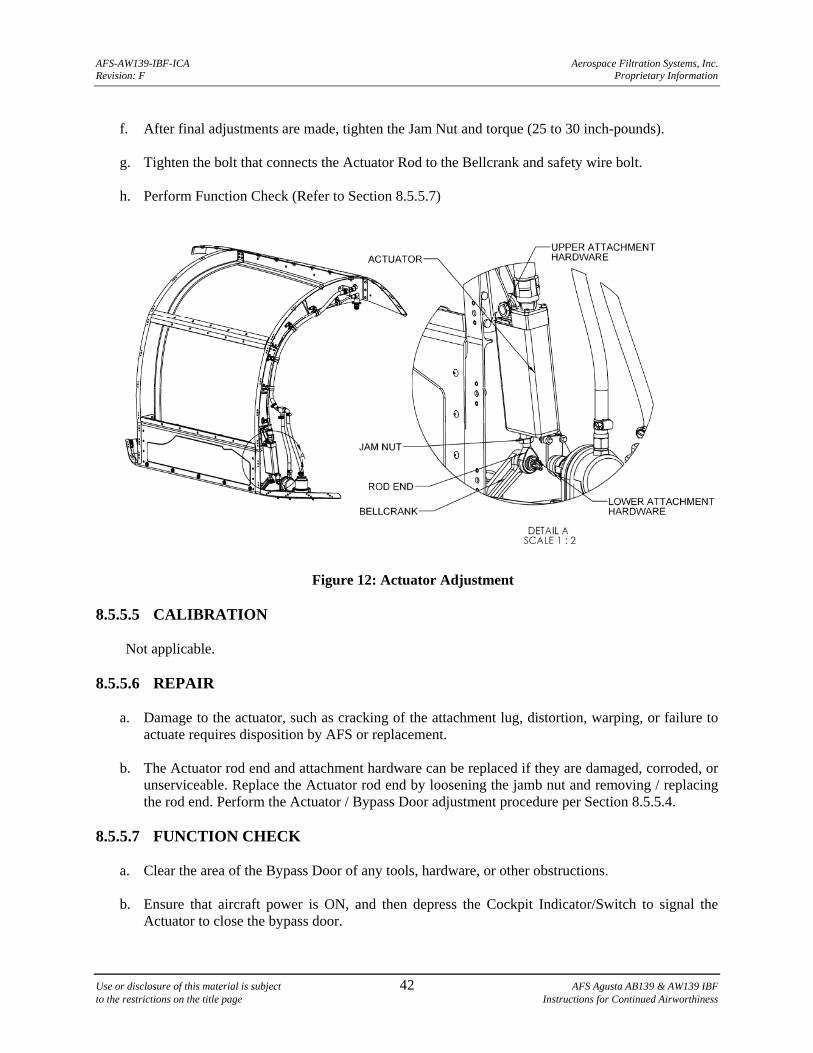
AFS-AW139-IBF-ICA Aerospace Filtration Systems, Inc. Revision: F Proprietary Information
Use or disclosure of this material is subject 42 AFS Agusta AB139 & AW139 IBF to the restrictions on the title page Instructions for Continued Airworthiness
f. After final adjustments are made, tighten the Jam Nut and torque (25 to 30 inch-pounds).
g. Tighten the bolt that connects the Actuator Rod to the Bellcrank and safety wire bolt.
h. Perform Function Check (Refer to Section 8.5.5.7)
Figure 12: Actuator Adjustment 8.5.5.5 CALIBRATION
Not applicable.
8.5.5.6 REPAIR
a. Damage to the actuator, such as cracking of the attachment lug, distortion, warping, or failure to actuate requires disposition by AFS or replacement.
b. The Actuator rod end and attachment hardware can be replaced if they are damaged, corroded, or
unserviceable. Replace the Actuator rod end by loosening the jamb nut and removing / replacing the rod end. Perform the Actuator / Bypass Door adjustment procedure per Section 8.5.5.4.
8.5.5.7 FUNCTION CHECK
a. Clear the area of the Bypass Door of any tools, hardware, or other obstructions. b. Ensure that aircraft power is ON, and then depress the Cockpit Indicator/Switch to signal the
Actuator to close the bypass door.
AFS-AW139-IBF-ICA Aerospace Filtration Systems, Inc. Revision: F Proprietary Information
Use or disclosure of this material is subject 43 AFS Agusta AB139 & AW139 IBF to the restrictions on the title page Instructions for Continued Airworthiness
c. Inspect the Bypass Door Assembly Seal compression (the seal should be in contact with the perimeter of the Bypass Door Assembly and surrounding framework with no visible gaps, the seal should be slightly compressed).
d. Depress the Cockpit Indicator/Switch to signal the Actuator to open the bypass door (the
BYPASS section of the switch should illuminate when the actuator reaches its full stroke, if the light does not illuminate contact AFS).
e. Depress the Cockpit Indicator/Switch to return the Bypass Door to the closed position and aircraft
power may now be removed if desired. 8.5.5.8 INSTALLATION
CAUTION
THIS PROCEDURE INTRODUCES THE POSSIBILITY OF ENGINE FOD.
a. With the Actuator extended, locate Actuator and install two (2) bolts to secure the Actuator to the Actuator Supports and the Upper Filter Actuator Support.
b. Connect and secure electrical connector at Actuator.
c. Apply Aircraft electrical power.
d. Depress the Cockpit Indicator/Switch to close the Bypass door and perform functional check per
Section 8.5.5.7.
e. Upon completion of Bypass Door Function Check remove engine inlet protection.
f. Replace the Aft Fairing and Filter Assemblies that was removed to gain access to the Actuator. Ensure that aircraft power is OFF.
8.5.6 WIRING, WIRING HARNESS, CONNECTORS, BACKSHELLS, CIRCUIT
BREAKER (Refer to Appendix A, Figures A-31 thru A-39)
8.5.6.1 REMOVAL
a. Prepare aircraft for work performed on the electrical system by disconnecting the battery. b. Remove hardware, clamps, spiral wrap from component, as applicable. Tag interfacing
components for later installation. Remove affected components. 8.5.6.2 INSPECTION
The IBF wiring, wiring harness and associated components are constructed of standard aircraft wire and connectors. Standard aircraft maintenance procedures should be used for inspections and repair of the harness and connectors. Routine aircraft maintenance should include visual inspection for evidence of chafing, damage, corrosion and insuring the circuit breaker and all pins, connectors, and
AFS-AW139-IBF-ICA Aerospace Filtration Systems, Inc. Revision: F Proprietary Information
Use or disclosure of this material is subject 44 AFS Agusta AB139 & AW139 IBF to the restrictions on the title page Instructions for Continued Airworthiness
backshells are secure. Inspect wiring, wiring harness and associated components per AC 43.13-1B, Chapter 11.
8.5.6.3 TROUBLESHOOTING
a. See Table 3 for troubleshooting guidance. b. See Appendix A, Figures A-31 thru A-39 for wiring diagram, wire marking and identification,
routing, and installation information. 8.5.6.4 ADJUSTMENT / CALIBRATION
Not applicable.
8.5.6.5 REPAIR
Standard aircraft maintenance procedures should be used for repair of the wiring, wire harness and associated components. See Appendix A, Figures A-31 thru A-39 for wiring diagram, wire marking and identification, routing, and installation information. Perform repairs to affected components per AC 43.13-1B, Chapter 11.
8.5.6.6 INSTALLATION
a. Prepare aircraft for work performed on the electrical system by disconnecting the battery. b. Install affected component using appropriate hardware. Connect wiring per wiring diagram. Install
clamps, spiral wrap and heat shrink as applicable to affected components per AC 43.13-1B, Chapter 11.
8.6 PROTECTIVE TREATMENT
a. The assemblies and structural components of the IBF system are composed primarily of aluminum alloy materials and 304 Stainless Steel. All components, except for standard hardware components and fasteners, and vendor components, are coated with an epoxy primer. Scratched or damaged aluminum components should be touched up with a small paint brush dipped in epoxy primer. Prepare epoxy primer per manufacturer’s instructions.
b. Aircraft finishes scratched or damaged should be recoated with the finish specified in the aircraft
maintenance records and maintenance manual.
c. For the systems and electrical components, there are no protective treatments specified. Contact AFS for disposition of damaged components, or replace the damaged component.
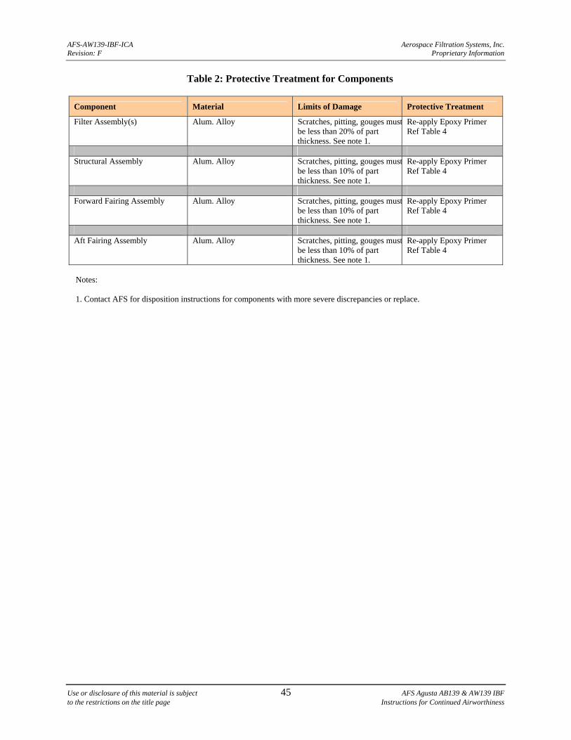
AFS-AW139-IBF-ICA Aerospace Filtration Systems, Inc. Revision: F Proprietary Information
Use or disclosure of this material is subject 45 AFS Agusta AB139 & AW139 IBF to the restrictions on the title page Instructions for Continued Airworthiness
Table 2: Protective Treatment for Components
Component Material Limits of Damage Protective Treatment
Filter Assembly(s) Alum. Alloy Scratches, pitting, gouges mustbe less than 20% of part thickness. See note 1.
Re-apply Epoxy Primer Ref Table 4
Structural Assembly Alum. Alloy Scratches, pitting, gouges must
be less than 10% of part thickness. See note 1.
Re-apply Epoxy Primer Ref Table 4
Forward Fairing Assembly Alum. Alloy Scratches, pitting, gouges must
be less than 10% of part thickness. See note 1.
Re-apply Epoxy Primer Ref Table 4
Aft Fairing Assembly Alum. Alloy Scratches, pitting, gouges must
be less than 10% of part thickness. See note 1.
Re-apply Epoxy Primer Ref Table 4
Notes:
1. Contact AFS for disposition instructions for components with more severe discrepancies or replace.
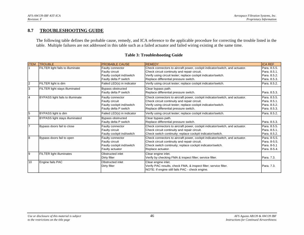
AFS-AW139-IBF-KIT-ICA Aerospace Filtration Systems, Inc. Revision: F Proprietary Information
Use or disclosure of this material is subject 46 AFS Agusta AB139 & AW139 IBF to the restrictions on the title page Instructions for Continued Airworthiness
8.7 TROUBLESHOOTING GUIDE
The following table defines the probable cause, remedy, and ICA reference to the applicable procedure for correcting the trouble listed in the table. Multiple failures are not addressed in this table such as a failed actuator and failed wiring existing at the same time.
Table 3: Troubleshooting Guide
ITEM TROUBLE PROBABLE CAUSE REMEDY ICA REF1 FILTER light fails to illuminate Faulty connector
Faulty circuitFaulty cockpit ind/switchFaulty delta P switch
Check connectors to aircraft power, cockpit indicator/switch, and actuator.Check circuit continuity and repair circuit.Verify using circuit tester; replace cockpit indicator/switch.Replace differential pressure switch.
Para. 8.5.5.Para. 8.5.1.Para. 8.5.2.Para. 8.5.3.
2 FILTER light is dim Failed LED(s) in indicator Verify using circuit tester; replace cockpit indicator/switch. Para. 8.5.2.
3 FILTER light stays illuminated Bypass obstructedFaulty delta P switch
Clear bypass path.Replace differential pressure switch. Para. 8.5.3.
4 BYPASS light fails to illuminate Faulty connectorFaulty circuitFaulty cockpit ind/switchFaulty delta P switch
Check connectors to aircraft power, cockpit indicator/switch, and actuator.Check circuit continuity and repair circuit.Verify using circuit tester; replace cockpit indicator/switch.Replace differential pressure switch.
Para. 8.5.5.Para. 8.5.1.Para. 8.5.2.Para. 8.5.3.
5 BYPASS light is dim Failed LED(s) in indicator Verify using circuit tester; replace cockpit indicator/switch. Para. 8.5.2.
6 BYPASS light stays illuminated Bypass obstructedFaulty delta P switch
Clear bypass path.Replace differential pressure switch. Para. 8.5.3.
7 Bypass doors fail to close Faulty connectorFaulty circuitFaulty cockpit ind/switch
Check connectors to aircraft power, cockpit indicator/switch, and actuator.Check circuit continuity and repair circuit.Check switch continuity; replace cockpit indicator/switch.
Para. 8.5.5.Para. 8.5.1.Para. 8.5.2.
8 Bypass doors fail to open Faulty connectorFaulty circuitFaulty cockpit ind/switch Faulty actuator
Check connectors to aircraft power, cockpit indicator/switch, and actuator.Check circuit continuity and repair circuit.Check switch continuity; replace cockpit indicator/switch.Replace actuator.
Para. 8-5.5.Para. 8-5.5.Para. 8-5.1Para. 8-5.4.
9 FILTER light illuminates Obstructed inletDirty filter
Clear engine inlet.Verify by checking FMA & inspect filter; service filter. Para. 7.3.
10 Engine fails PAC Obstructed inletDirty filter
Clear engine inlet.Verify PAC results, check FMA, & inspect filter; service filter.NOTE: If engine still fails PAC - check engine.
Para. 7.3.
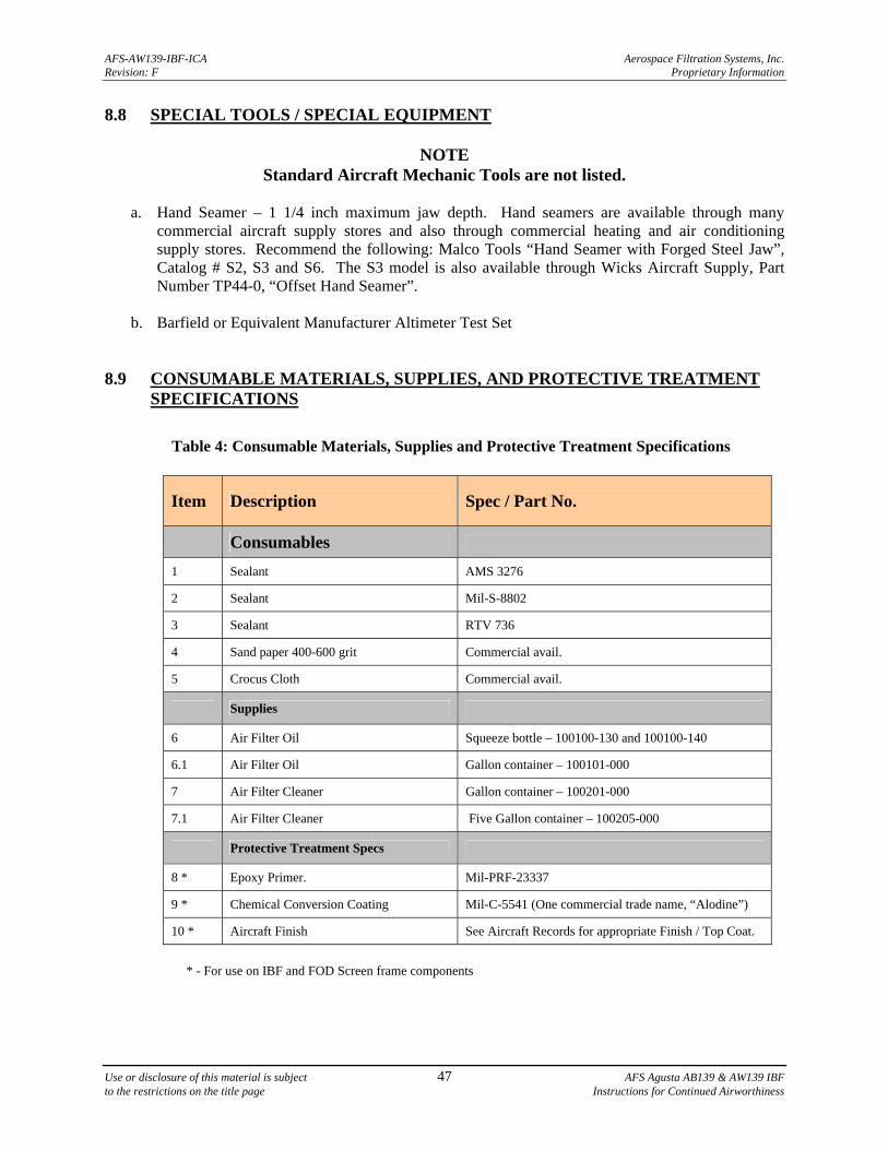
AFS-AW139-IBF-ICA Aerospace Filtration Systems, Inc. Revision: F Proprietary Information
Use or disclosure of this material is subject 47 AFS Agusta AB139 & AW139 IBF to the restrictions on the title page Instructions for Continued Airworthiness
8.8 SPECIAL TOOLS / SPECIAL EQUIPMENT
NOTE Standard Aircraft Mechanic Tools are not listed.
a. Hand Seamer – 1 1/4 inch maximum jaw depth. Hand seamers are available through many
commercial aircraft supply stores and also through commercial heating and air conditioning supply stores. Recommend the following: Malco Tools “Hand Seamer with Forged Steel Jaw”, Catalog # S2, S3 and S6. The S3 model is also available through Wicks Aircraft Supply, Part Number TP44-0, “Offset Hand Seamer”.
b. Barfield or Equivalent Manufacturer Altimeter Test Set
8.9 CONSUMABLE MATERIALS, SUPPLIES, AND PROTECTIVE TREATMENT
SPECIFICATIONS
Table 4: Consumable Materials, Supplies and Protective Treatment Specifications
Item Description Spec / Part No.
Consumables
1 Sealant AMS 3276
2 Sealant Mil-S-8802
3 Sealant RTV 736
4 Sand paper 400-600 grit Commercial avail.
5 Crocus Cloth Commercial avail.
Supplies
6 Air Filter Oil Squeeze bottle – 100100-130 and 100100-140
6.1 Air Filter Oil Gallon container – 100101-000
7 Air Filter Cleaner Gallon container – 100201-000
7.1 Air Filter Cleaner Five Gallon container – 100205-000
Protective Treatment Specs
8 * Epoxy Primer. Mil-PRF-23337
9 * Chemical Conversion Coating Mil-C-5541 (One commercial trade name, “Alodine”)
10 * Aircraft Finish See Aircraft Records for appropriate Finish / Top Coat.
* - For use on IBF and FOD Screen frame components
AFS-AW139-IBF-ICA Aerospace Filtration Systems, Inc. Revision: F Proprietary Information
Use or disclosure of this material is subject 48 AFS Agusta AB139 & AW139 IBF to the restrictions on the title page Instructions for Continued Airworthiness
9 FOD SCREEN MAINTENANCE
9.1 MAINTENANCE GENERAL
CAUTION
THOROUGHLY REVIEW AND BECOME FAMILIAR WITH THE APPENDIX A - PARTS FIGURES BEFORE PERFORMING MAINTENANCE ON THE IBF SYSTEM.
NOTE
Except where otherwise indicated, all torque values shall be in accordance with Chapter 7 of FAA Advisory Circular AC 43.13-1B.
a. The components of the system are divided, generally as a scope of work, into Plenum Assembly
(consisting of Forward, Aft, and Upper Frame Assemblies and Actuator Support Assembly), FOD Screen Assembly, Lower Side Filter Supports, and Systems and Electrical components throughout the manual. Refer to Appendix A, Figures A-1 thru A-44. Table 1 gives a recommended inspection schedule for the components of the system. The troubleshooting guide in Table 3 provides additional guidance for performing inspections when encountering trouble with the system.
b. The maintenance chapter is organized by removal, inspection, troubleshooting, adjustment,
calibration and/or repair, and installation for the major components noted above, as applicable to the particular component. For some components a functional check is included. Not all components will require adjustment, or calibration, or have any approved functional check or repair procedures. Contact AFS for possible repairs when not listed in this manual. In some cases defective components will require replacement.
c. In general, visually inspect all structural components for oversized or elongated holes,
deformation, cracks, corrosion, missing fasteners or components, fretting, galling, etc. Any component exhibiting these conditions requires repair or replacement.
d. In general, visually inspect fasteners for damaged or missing threads, in both the bolt or screw
and the nut or nut plate. If a self-locking fastener can be fully threaded by hand, replace the self-locking fastener.
e. In general, visually inspect all electrical connections for security, corrosion, arcing, breakdown of
insulation, and overheating. Repair or replace components exhibiting defects. Inspect and repair components per Agusta technical manuals or AC 43.13-1B, Chapter 11.
AFS-AW139-IBF-ICA Aerospace Filtration Systems, Inc. Revision: F Proprietary Information
Use or disclosure of this material is subject 49 AFS Agusta AB139 & AW139 IBF to the restrictions on the title page Instructions for Continued Airworthiness
9.2 COMPONENTS - GENERAL DESCRIPTION 9.2.1 FOD SCREEN ASSY
a. FOD Screen Assembly - The FOD Screen Assembly is composed of a stainless steel mesh secured into the aluminum alloy frame assembly.
9.2.2 PLENUM ASSEMBLY (STRUCTURAL COMPONENTS)
a. Reference Section 8.2.2 9.2.3 SYSTEMS AND ELECTRICAL COMPONENTS
a. Reference Section 8.2.3
9.3 FOD SCREEN ASSY 9.3.1 FOD SCREEN ASSY 9.3.1.1 REMOVAL – FOD SCREEN ASSY
CAUTION
UPON REMOVAL OF ANY SCREEN ASSEMBLY COVER THE ENGINE INLET (AS SOON AS THERE IS ACCESS TO THE INLET), TO PREVENT FOREIGN OBJECT DAMAGE (FOD).
a. Obtain required equipment to safely access and perform maintenance on the screens (i.e. ladder, lift scaffolding, etc.)
b. To remove screens – Loosen the eighteen captive bolts that retain each FOD Screen Assembly to
the Plenum Assembly.
c. Use a plastic scraper to gently break any seal between the plenum structure and the seal itself. The filter assembly must be carefully removed so as not to damage the filter seal.
d. Repeat steps b and c for all screens being removed.
9.3.1.2 INSPECTION – FOD SCREEN ASSY
a. Visually inspect the screen mesh on both sides of the screen assembly. Minor dents can be straightening or removed. If screen mesh is cracked or separated, replace screen assembly.
9.3.1.3 ADJUSTMENT - FOD SCREEN ASSY
No adjustment is required.
AFS-AW139-IBF-ICA Aerospace Filtration Systems, Inc. Revision: F Proprietary Information
Use or disclosure of this material is subject 50 AFS Agusta AB139 & AW139 IBF to the restrictions on the title page Instructions for Continued Airworthiness
9.3.1.4 CALIBRATION - FOD SCREEN ASSY
No calibration is required. 9.3.1.5 REPAIR - - FOD SCREEN ASSY
a. No repairs are authorized. b. Any damage to the FOD screen frames such as cracking requires the FOD screen assembly to
be returned to AFS for evaluation and disposition, or replacement. Any damage to the FOD screen frames such as warping or distortion (to the extent that a good fit of the FOD screen frame, when installed and/or torqued, does not permit the FOD screen assembly to sit flush against the Plenum assembly) requires the FOD screen assembly be returned to AFS for evaluation and disposition, or be replaced.
9.3.1.10 INSTALLATION
a. Locate and place the FOD screen on the plenum assembly, aligning the captive bolts with the receptacles in the plenum assembly.
b. Tighten the eighteen captive bolts that retain each FOD Screen Assembly to the Plenum
Assembly. 9.4 STRUCTURAL COMPONENTS
a. Reference Section 8.4 9.5 SYSTEMS AND ELECTRICAL COMPONENTS
a. Reference Section 8.5 9.6 PROTECTIVE TREATMENT
a. Reference Section 8.6 9.7 TROUBLESHOOTING GUIDE
a. Not applicable 9.8 SPECIAL TOOLS / SPECIAL EQUIPMENT
a. Not applicable 9.9 CONSUMABLE MATERIALS, SUPPLIES, AND PROTECTIVE TREATMENT
SPECIFICATIONS
a. Reference Section 8.9
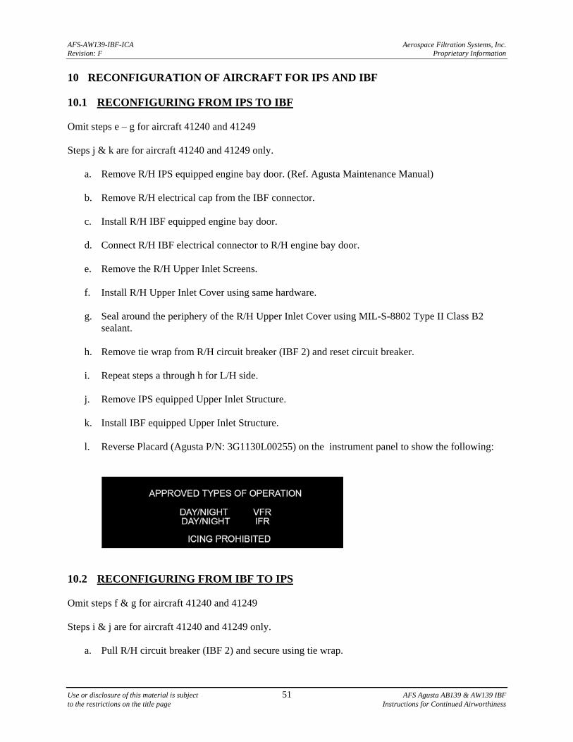
AFS-AW139-IBF-ICA Aerospace Filtration Systems, Inc. Revision: F Proprietary Information
Use or disclosure of this material is subject 51 AFS Agusta AB139 & AW139 IBF to the restrictions on the title page Instructions for Continued Airworthiness
10 RECONFIGURATION OF AIRCRAFT FOR IPS AND IBF 10.1 RECONFIGURING FROM IPS TO IBF Omit steps e – g for aircraft 41240 and 41249 Steps j & k are for aircraft 41240 and 41249 only.
a. Remove R/H IPS equipped engine bay door. (Ref. Agusta Maintenance Manual)
b. Remove R/H electrical cap from the IBF connector.
c. Install R/H IBF equipped engine bay door.
d. Connect R/H IBF electrical connector to R/H engine bay door.
e. Remove the R/H Upper Inlet Screens.
f. Install R/H Upper Inlet Cover using same hardware.
g. Seal around the periphery of the R/H Upper Inlet Cover using MIL-S-8802 Type II Class B2 sealant.
h. Remove tie wrap from R/H circuit breaker (IBF 2) and reset circuit breaker.
i. Repeat steps a through h for L/H side.
j. Remove IPS equipped Upper Inlet Structure.
k. Install IBF equipped Upper Inlet Structure.
l. Reverse Placard (Agusta P/N: 3G1130L00255) on the instrument panel to show the following:
10.2 RECONFIGURING FROM IBF TO IPS Omit steps f & g for aircraft 41240 and 41249 Steps i & j are for aircraft 41240 and 41249 only.
a. Pull R/H circuit breaker (IBF 2) and secure using tie wrap.
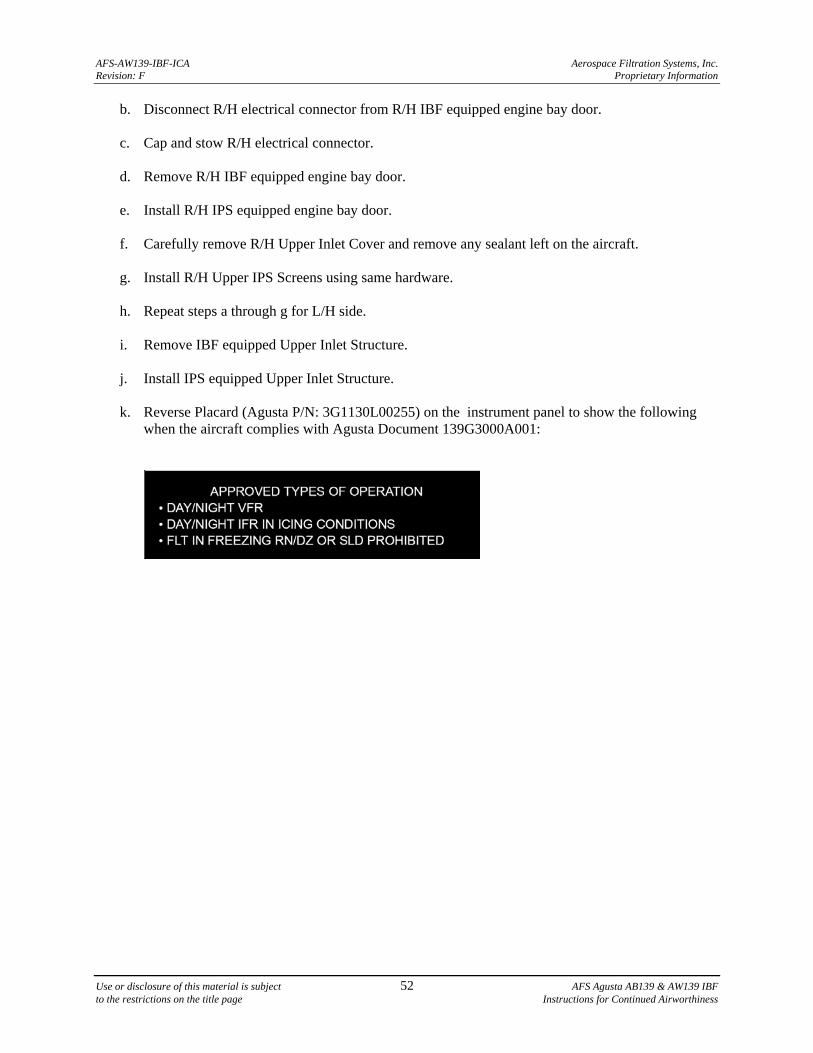
AFS-AW139-IBF-ICA Aerospace Filtration Systems, Inc. Revision: F Proprietary Information
Use or disclosure of this material is subject 52 AFS Agusta AB139 & AW139 IBF to the restrictions on the title page Instructions for Continued Airworthiness
b. Disconnect R/H electrical connector from R/H IBF equipped engine bay door.
c. Cap and stow R/H electrical connector.
d. Remove R/H IBF equipped engine bay door.
e. Install R/H IPS equipped engine bay door.
f. Carefully remove R/H Upper Inlet Cover and remove any sealant left on the aircraft.
g. Install R/H Upper IPS Screens using same hardware.
h. Repeat steps a through g for L/H side.
i. Remove IBF equipped Upper Inlet Structure.
j. Install IPS equipped Upper Inlet Structure.
k. Reverse Placard (Agusta P/N: 3G1130L00255) on the instrument panel to show the following when the aircraft complies with Agusta Document 139G3000A001:
AFS-AW139-IBF-ICA Aerospace Filtration Systems, Inc. Revision: F Proprietary Information
Use or disclosure of this material is subject A-1 AFS Agusta AB139 & AW139 IBF to the restrictions on the title page Instructions for Continued Airworthiness
APPENDIX A PARTS FIGURES
(Parts depicted in this appendix are L/H, R/H assemblies are denoted as -102 and R/H parts are denoted as -202)
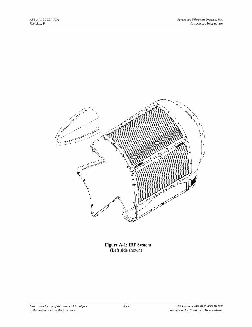
AFS-AW139-IBF-ICA Aerospace Filtration Systems, Inc. Revision: F Proprietary Information
Use or disclosure of this material is subject A-2 AFS Agusta AB139 & AW139 IBF to the restrictions on the title page Instructions for Continued Airworthiness
Figure A-1: IBF System (Left side shown)
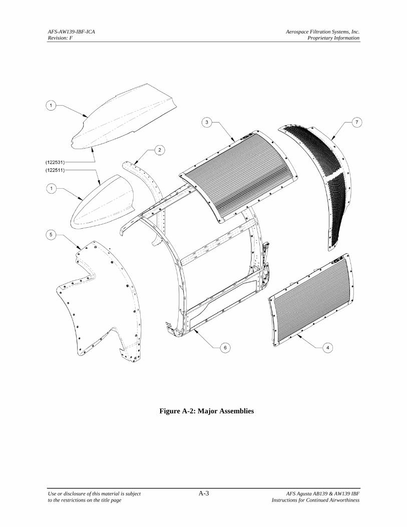
AFS-AW139-IBF-ICA Aerospace Filtration Systems, Inc. Revision: F Proprietary Information
Use or disclosure of this material is subject A-3 AFS Agusta AB139 & AW139 IBF to the restrictions on the title page Instructions for Continued Airworthiness
Figure A-2: Major Assemblies
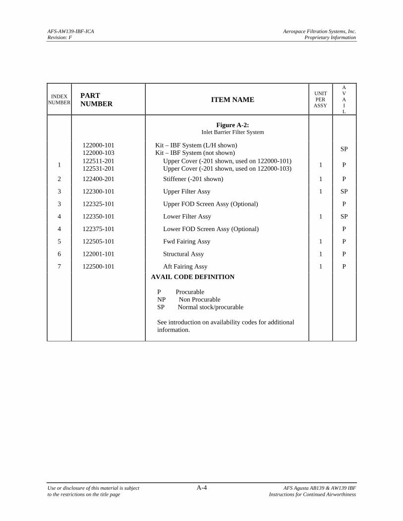
AFS-AW139-IBF-ICA Aerospace Filtration Systems, Inc. Revision: F Proprietary Information
Use or disclosure of this material is subject A-4 AFS Agusta AB139 & AW139 IBF to the restrictions on the title page Instructions for Continued Airworthiness
INDEX NUMBER
PART NUMBER
ITEM NAME UNIT PER
ASSY
A V A I L
Figure A-2: Inlet Barrier Filter System
122000-101 122000-103
Kit – IBF System (L/H shown) Kit – IBF System (not shown)
SP
1 122511-201 122531-201
Upper Cover (-201 shown, used on 122000-101) Upper Cover (-201 shown, used on 122000-103)
1 P
2 122400-201 Stiffener (-201 shown) 1 P
3 122300-101 Upper Filter Assy 1 SP
3 122325-101 Upper FOD Screen Assy (Optional) P
4 122350-101 Lower Filter Assy 1 SP
4 122375-101 Lower FOD Screen Assy (Optional) P
5 122505-101 Fwd Fairing Assy 1 P
6 122001-101 Structural Assy 1 P
7 122500-101 Aft Fairing Assy 1 P
AVAIL CODE DEFINITION P Procurable NP Non Procurable SP Normal stock/procurable See introduction on availability codes for additional information.
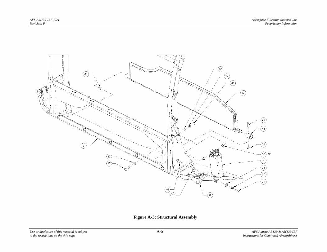
AFS-AW139-IBF-ICA Aerospace Filtration Systems, Inc. Revision: F Proprietary Information
Use or disclosure of this material is subject A-5 AFS Agusta AB139 & AW139 IBF to the restrictions on the title page Instructions for Continued Airworthiness
Figure A-3: Structural Assembly
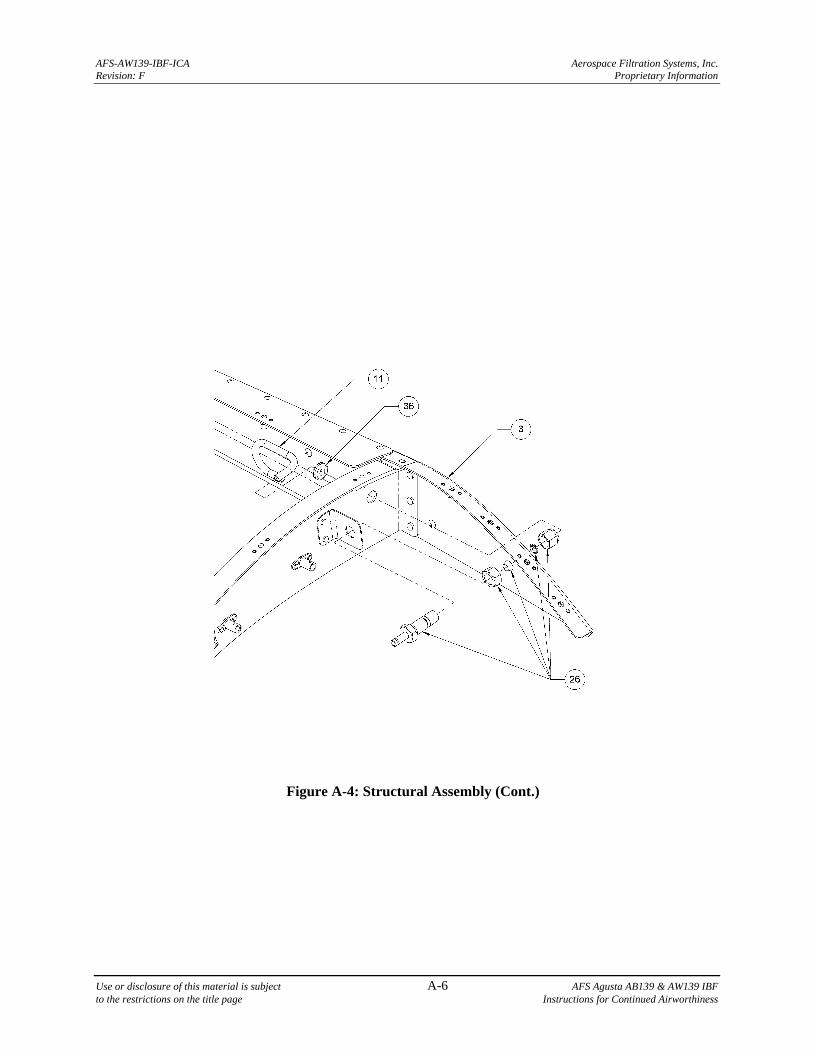
AFS-AW139-IBF-ICA Aerospace Filtration Systems, Inc. Revision: F Proprietary Information
Use or disclosure of this material is subject A-6 AFS Agusta AB139 & AW139 IBF to the restrictions on the title page Instructions for Continued Airworthiness
Figure A-4: Structural Assembly (Cont.)
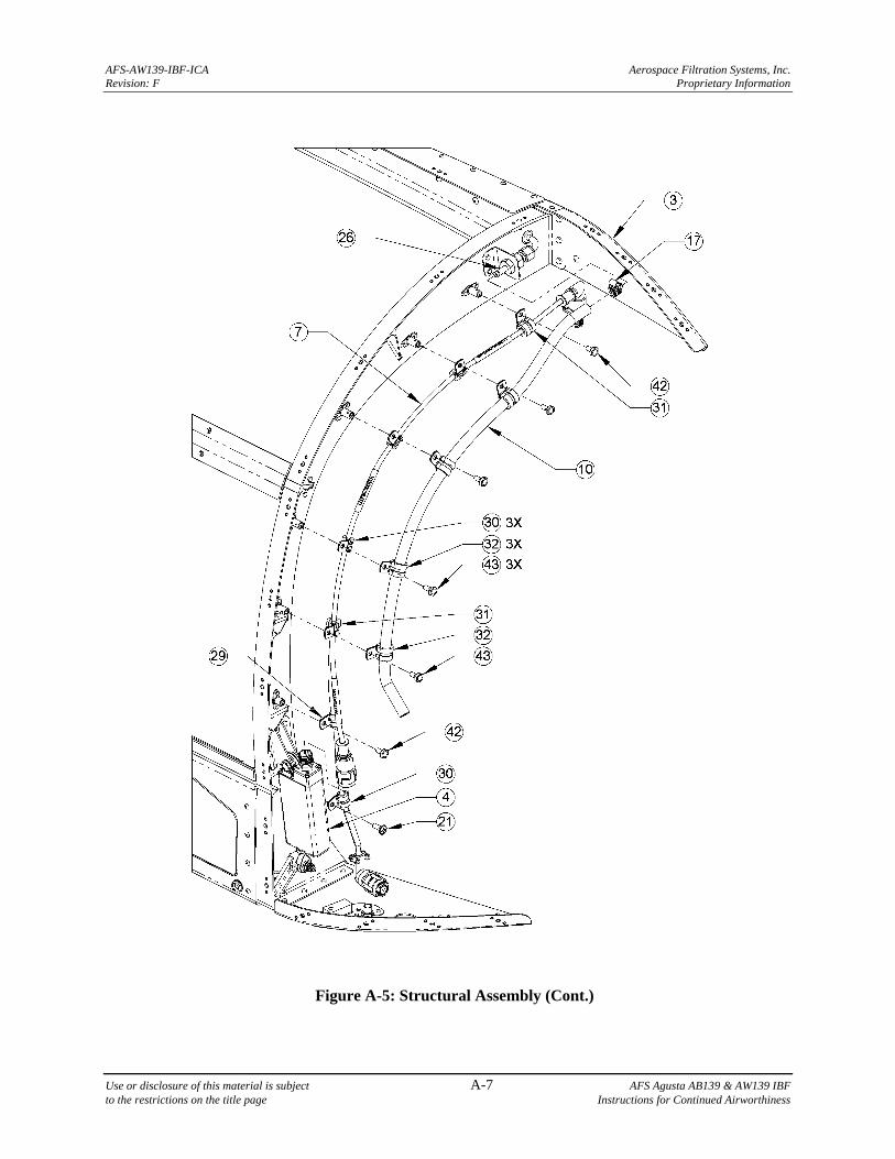
AFS-AW139-IBF-ICA Aerospace Filtration Systems, Inc. Revision: F Proprietary Information
Use or disclosure of this material is subject A-7 AFS Agusta AB139 & AW139 IBF to the restrictions on the title page Instructions for Continued Airworthiness
Figure A-5: Structural Assembly (Cont.)
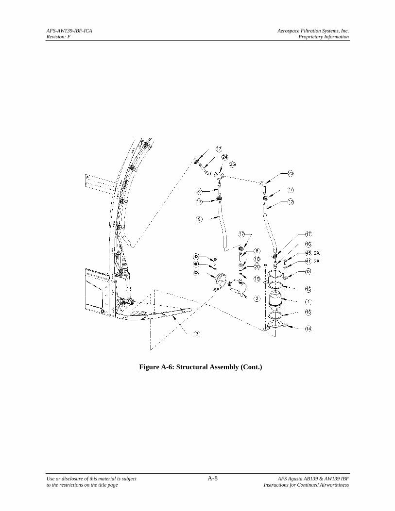
AFS-AW139-IBF-ICA Aerospace Filtration Systems, Inc. Revision: F Proprietary Information
Use or disclosure of this material is subject A-8 AFS Agusta AB139 & AW139 IBF to the restrictions on the title page Instructions for Continued Airworthiness
Figure A-6: Structural Assembly (Cont.)
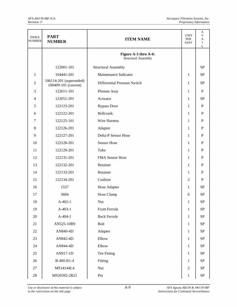
AFS-AW139-IBF-ICA Aerospace Filtration Systems, Inc. Revision: F Proprietary Information
Use or disclosure of this material is subject A-9 AFS Agusta AB139 & AW139 IBF to the restrictions on the title page Instructions for Continued Airworthiness
INDEX NUMBER
PART NUMBER
ITEM NAME UNIT PER
ASSY
A V A I L
Figure A-3 thru A-6: Structural Assembly
122001-101 Structural Assembly SP
1 104441-201 Maintenance Indicator 1 SP
2 106114-201 (superseded)
100409-101 (current) Differential Pressure Switch 1 SP
3 122011-101 Plenum Assy 1 P
4 122051-201 Actuator 1 SP
5 122123-201 Bypass Door 1 P
6 122122-201 Bellcrank 1 P
7 122125-101 Wire Harness 1 P
8 122126-201 Adapter 1 P
9 122127-201 Delta-P Sensor Hose 1 P
10 122128-201 Sensor Hose 1 P
11 122129-201 Tube 1 P
12 122131-201 FMA Sensor Hose 1 P
13 122132-201 Retainer 1 P
14 122133-201 Retainer 1 P
15 122134-201 Cushion 2 P
16 1537 Hose Adapter 1 SP
17 3604 Hose Clamp 6 SP
18 A-402-1 Nut 1 SP
19 A-403-1 Front Ferrule 1 SP
20 A-404-1 Back Ferrule 1 SP
21 AN525-10R9 Bolt 1 SP
22 AN840-4D Adapter 1 SP
23 AN842-4D Elbow 1 SP
24 AN844-4D Elbow 1 SP
25 AN917-1D Tee Fitting 1 SP
26 B-400-R1-4 Fitting 1 SP
27 MS14144L4 Nut 2 SP
28 MS20392-2R21 Pin 1 SP
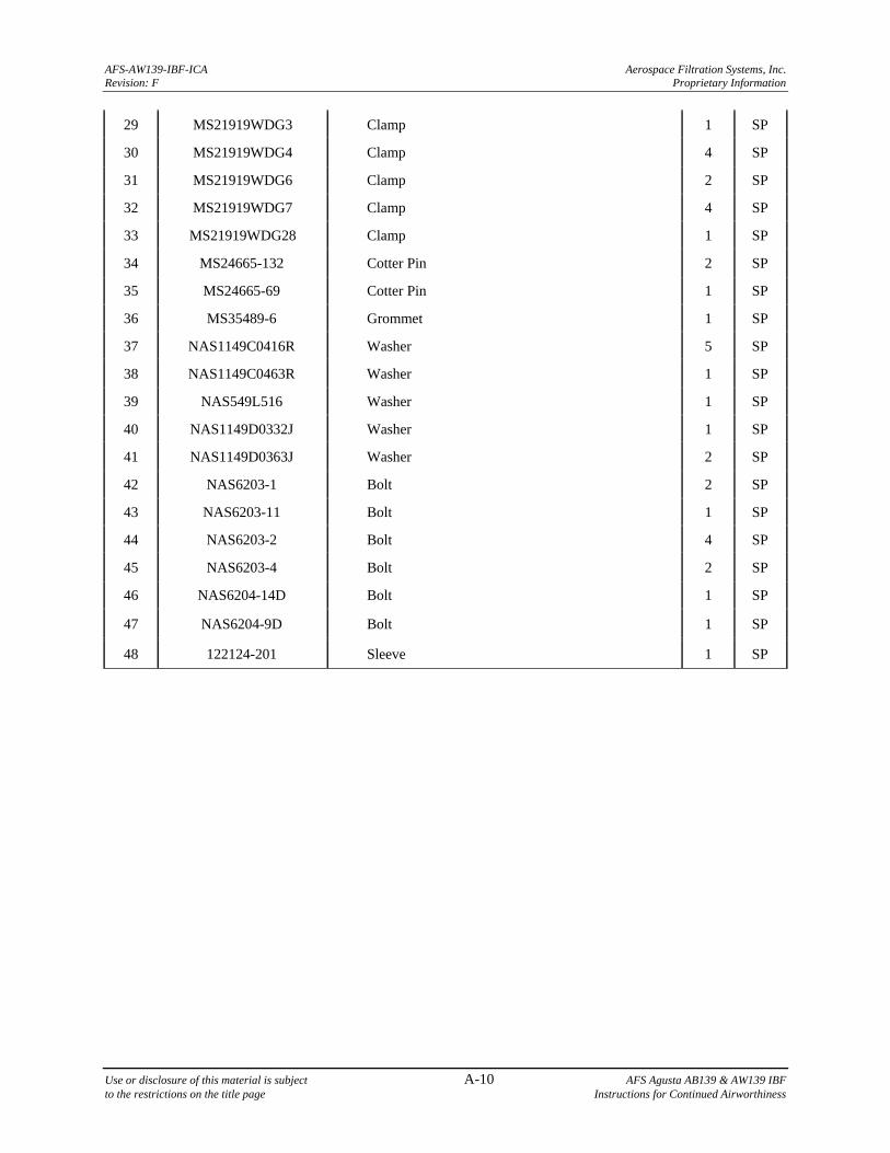
AFS-AW139-IBF-ICA Aerospace Filtration Systems, Inc. Revision: F Proprietary Information
Use or disclosure of this material is subject A-10 AFS Agusta AB139 & AW139 IBF to the restrictions on the title page Instructions for Continued Airworthiness
29 MS21919WDG3 Clamp 1 SP
30 MS21919WDG4 Clamp 4 SP
31 MS21919WDG6 Clamp 2 SP
32 MS21919WDG7 Clamp 4 SP
33 MS21919WDG28 Clamp 1 SP
34 MS24665-132 Cotter Pin 2 SP
35 MS24665-69 Cotter Pin 1 SP
36 MS35489-6 Grommet 1 SP
37 NAS1149C0416R Washer 5 SP
38 NAS1149C0463R Washer 1 SP
39 NAS549L516 Washer 1 SP
40 NAS1149D0332J Washer 1 SP
41 NAS1149D0363J Washer 2 SP
42 NAS6203-1 Bolt 2 SP
43 NAS6203-11 Bolt 1 SP
44 NAS6203-2 Bolt 4 SP
45 NAS6203-4 Bolt 2 SP
46 NAS6204-14D Bolt 1 SP
47 NAS6204-9D Bolt 1 SP
48 122124-201 Sleeve 1 SP
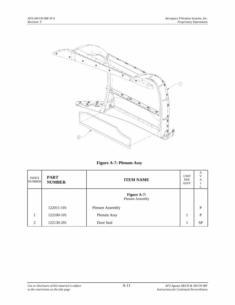
AFS-AW139-IBF-ICA Aerospace Filtration Systems, Inc. Revision: F Proprietary Information
Use or disclosure of this material is subject A-11 AFS Agusta AB139 & AW139 IBF to the restrictions on the title page Instructions for Continued Airworthiness
Figure A-7: Plenum Assy
INDEX NUMBER
PART NUMBER
ITEM NAME UNIT PER
ASSY
A V A I L
Figure A-7: Plenum Assembly
122011-101 Plenum Assembly P
1 122100-101 Plenum Assy 1 P
2 122130-201 Door Seal 1 SP
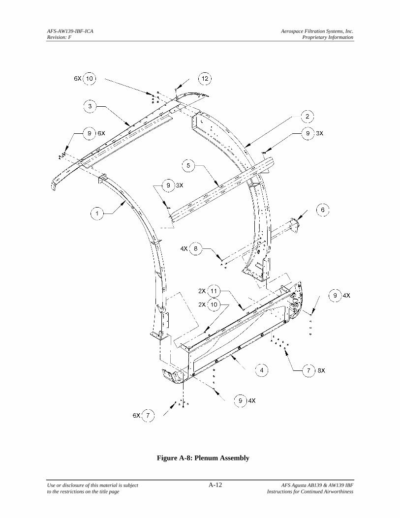
AFS-AW139-IBF-ICA Aerospace Filtration Systems, Inc. Revision: F Proprietary Information
Use or disclosure of this material is subject A-12 AFS Agusta AB139 & AW139 IBF to the restrictions on the title page Instructions for Continued Airworthiness
Figure A-8: Plenum Assembly
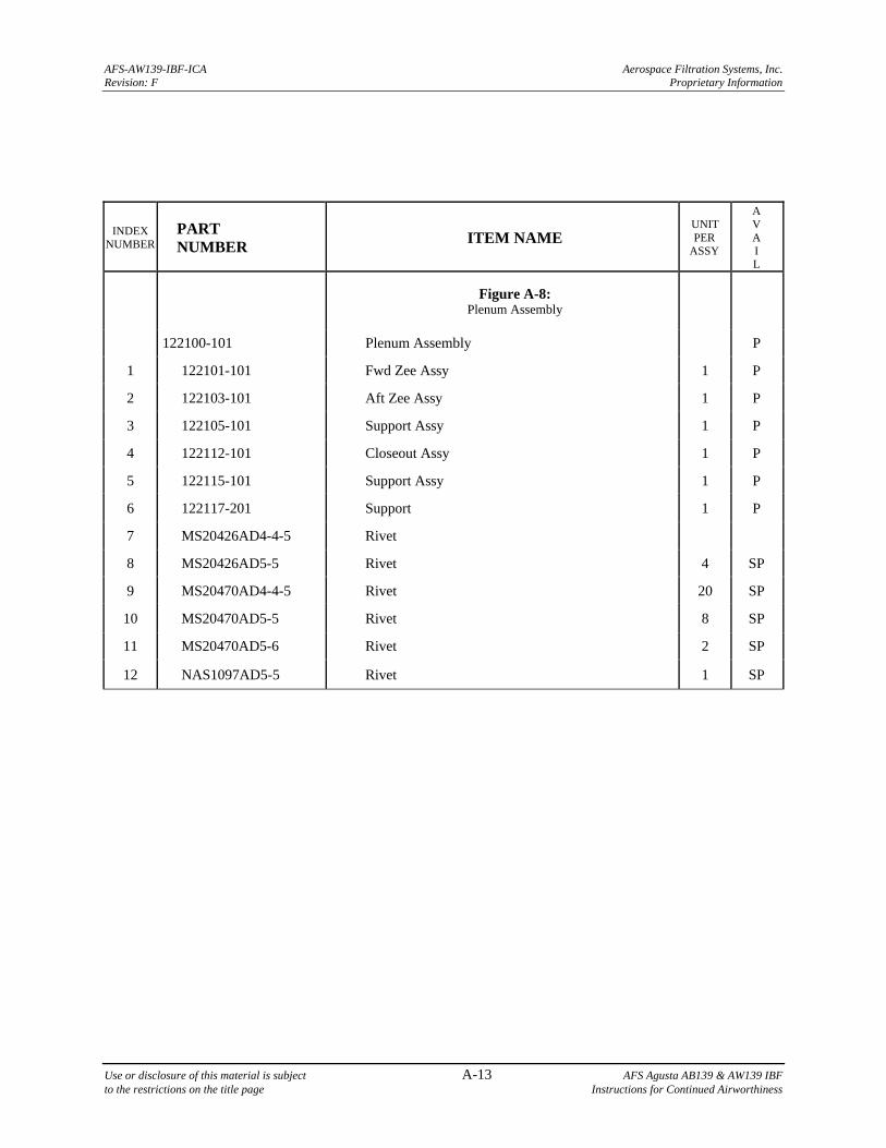
AFS-AW139-IBF-ICA Aerospace Filtration Systems, Inc. Revision: F Proprietary Information
Use or disclosure of this material is subject A-13 AFS Agusta AB139 & AW139 IBF to the restrictions on the title page Instructions for Continued Airworthiness
INDEX NUMBER
PART NUMBER
ITEM NAME UNIT PER
ASSY
A V A I L
Figure A-8: Plenum Assembly
122100-101 Plenum Assembly P
1 122101-101 Fwd Zee Assy 1 P
2 122103-101 Aft Zee Assy 1 P
3 122105-101 Support Assy 1 P
4 122112-101 Closeout Assy 1 P
5 122115-101 Support Assy 1 P
6 122117-201 Support 1 P
7 MS20426AD4-4-5 Rivet
8 MS20426AD5-5 Rivet 4 SP
9 MS20470AD4-4-5 Rivet 20 SP
10 MS20470AD5-5 Rivet 8 SP
11 MS20470AD5-6 Rivet 2 SP
12 NAS1097AD5-5 Rivet 1 SP
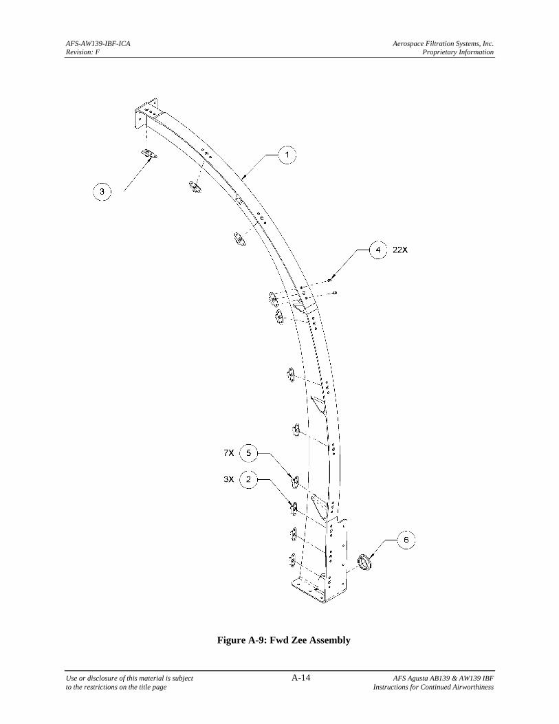
AFS-AW139-IBF-ICA Aerospace Filtration Systems, Inc. Revision: F Proprietary Information
Use or disclosure of this material is subject A-14 AFS Agusta AB139 & AW139 IBF to the restrictions on the title page Instructions for Continued Airworthiness
Figure A-9: Fwd Zee Assembly
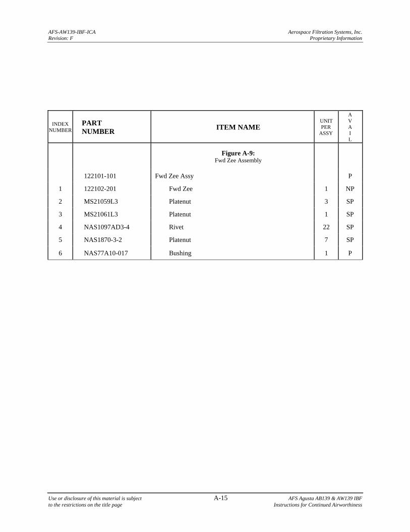
AFS-AW139-IBF-ICA Aerospace Filtration Systems, Inc. Revision: F Proprietary Information
Use or disclosure of this material is subject A-15 AFS Agusta AB139 & AW139 IBF to the restrictions on the title page Instructions for Continued Airworthiness
INDEX NUMBER
PART NUMBER
ITEM NAME UNIT PER
ASSY
A V A I L
Figure A-9: Fwd Zee Assembly
122101-101 Fwd Zee Assy P
1 122102-201 Fwd Zee 1 NP
2 MS21059L3 Platenut 3 SP
3 MS21061L3 Platenut 1 SP
4 NAS1097AD3-4 Rivet 22 SP
5 NAS1870-3-2 Platenut 7 SP
6 NAS77A10-017 Bushing 1 P
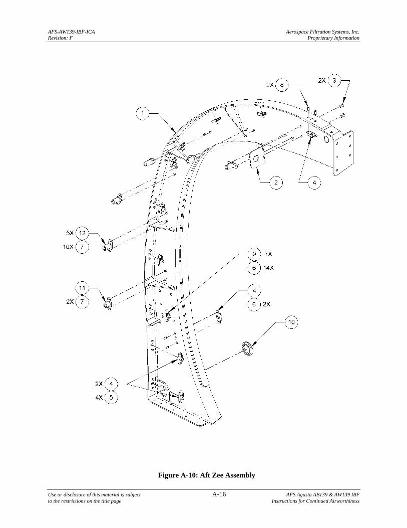
AFS-AW139-IBF-ICA Aerospace Filtration Systems, Inc. Revision: F Proprietary Information
Use or disclosure of this material is subject A-16 AFS Agusta AB139 & AW139 IBF to the restrictions on the title page Instructions for Continued Airworthiness
Figure A-10: Aft Zee Assembly
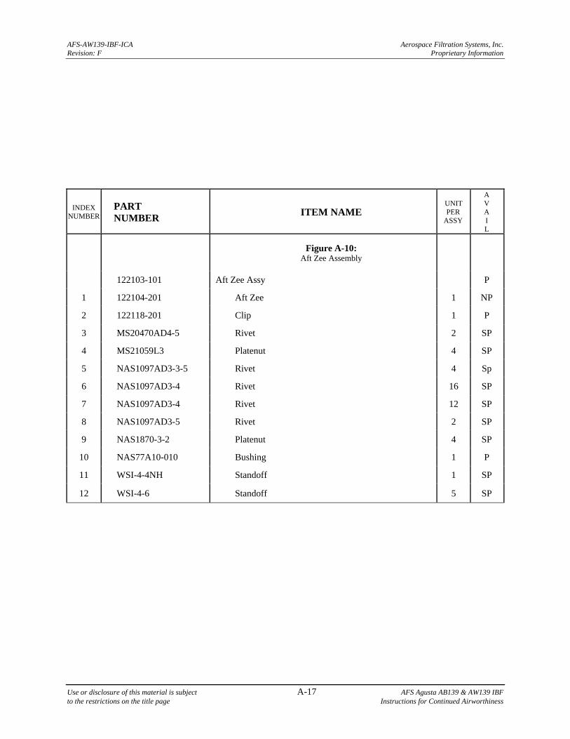
AFS-AW139-IBF-ICA Aerospace Filtration Systems, Inc. Revision: F Proprietary Information
Use or disclosure of this material is subject A-17 AFS Agusta AB139 & AW139 IBF to the restrictions on the title page Instructions for Continued Airworthiness
INDEX NUMBER
PART NUMBER
ITEM NAME UNIT PER
ASSY
A V A I L
Figure A-10: Aft Zee Assembly
122103-101 Aft Zee Assy P
1 122104-201 Aft Zee 1 NP
2 122118-201 Clip 1 P
3 MS20470AD4-5 Rivet 2 SP
4 MS21059L3 Platenut 4 SP
5 NAS1097AD3-3-5 Rivet 4 Sp
6 NAS1097AD3-4 Rivet 16 SP
7 NAS1097AD3-4 Rivet 12 SP
8 NAS1097AD3-5 Rivet 2 SP
9 NAS1870-3-2 Platenut 4 SP
10 NAS77A10-010 Bushing 1 P
11 WSI-4-4NH Standoff 1 SP
12 WSI-4-6 Standoff 5 SP
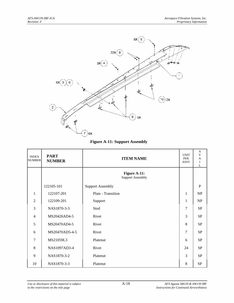
AFS-AW139-IBF-ICA Aerospace Filtration Systems, Inc. Revision: F Proprietary Information
Use or disclosure of this material is subject A-18 AFS Agusta AB139 & AW139 IBF to the restrictions on the title page Instructions for Continued Airworthiness
Figure A-11: Support Assembly
INDEX NUMBER
PART NUMBER
ITEM NAME UNIT PER
ASSY
A V A I L
Figure A-11: Support Assembly
122105-101 Support Assembly P
1 122107-201 Plate - Transition 1 NP
2 122109-201 Support 1 NP
3 NAS1870-3-3 Stud 7 SP
4 MS20426AD4-5 Rivet 3 SP
5 MS20470AD4-5 Rivet 8 SP
6 MS20470AD5-4-5 Rivet 7 SP
7 MS21059L3 Platenut 6 SP
8 NAS1097AD3-4 Rivet 24 SP
9 NAS1870-3-2 Platenut 3 SP
10 NAS1870-3-3 Platenut 8 SP
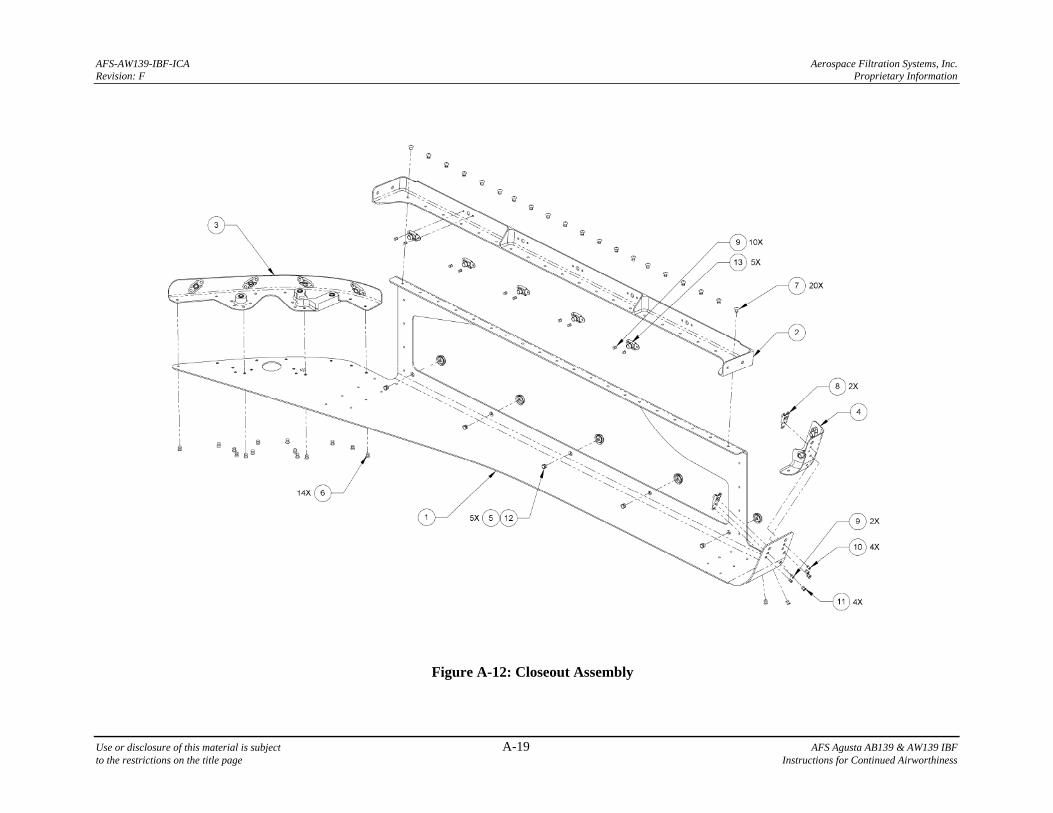
AFS-AW139-IBF-ICA Aerospace Filtration Systems, Inc. Revision: F Proprietary Information
Use or disclosure of this material is subject A-19 AFS Agusta AB139 & AW139 IBF to the restrictions on the title page Instructions for Continued Airworthiness
Figure A-12: Closeout Assembly
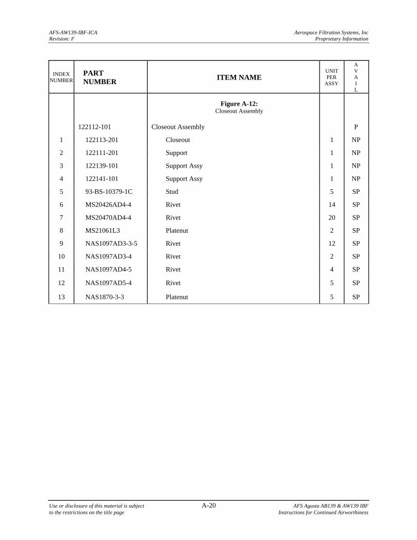
AFS-AW139-IBF-ICA Aerospace Filtration Systems, Inc Revision: F Proprietary Information
Use or disclosure of this material is subject A-20 AFS Agusta AB139 & AW139 IBF to the restrictions on the title page Instructions for Continued Airworthiness
INDEX NUMBER
PART NUMBER
ITEM NAME UNIT PER
ASSY
A V A I L
Figure A-12: Closeout Assembly
122112-101 Closeout Assembly P
1 122113-201 Closeout 1 NP
2 122111-201 Support 1 NP
3 122139-101 Support Assy 1 NP
4 122141-101 Support Assy 1 NP
5 93-BS-10379-1C Stud 5 SP
6 MS20426AD4-4 Rivet 14 SP
7 MS20470AD4-4 Rivet 20 SP
8 MS21061L3 Platenut 2 SP
9 NAS1097AD3-3-5 Rivet 12 SP
10 NAS1097AD3-4 Rivet 2 SP
11 NAS1097AD4-5 Rivet 4 SP
12 NAS1097AD5-4 Rivet 5 SP
13 NAS1870-3-3 Platenut 5 SP
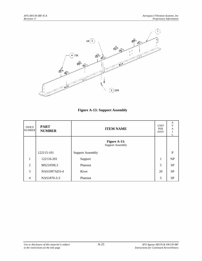
AFS-AW139-IBF-ICA Aerospace Filtration Systems, Inc Revision: F Proprietary Information
Use or disclosure of this material is subject A-21 AFS Agusta AB139 & AW139 IBF to the restrictions on the title page Instructions for Continued Airworthiness
Figure A-13: Support Assembly
INDEX NUMBER
PART NUMBER
ITEM NAME UNIT PER
ASSY
A V A I L
Figure A-13: Support Assembly
122115-101 Support Assembly P
1 122116-201 Support 1 NP
2 MS21059L3 Platenut 5 SP
3 NAS1097AD3-4 Rivet 20 SP
4 NAS1870-3-3 Platenut 5 SP
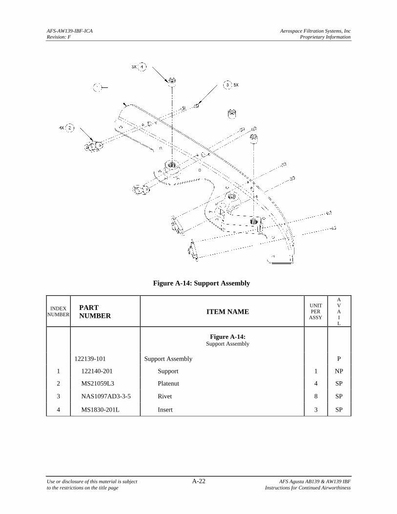
AFS-AW139-IBF-ICA Aerospace Filtration Systems, Inc Revision: F Proprietary Information
Use or disclosure of this material is subject A-22 AFS Agusta AB139 & AW139 IBF to the restrictions on the title page Instructions for Continued Airworthiness
Figure A-14: Support Assembly
INDEX NUMBER
PART NUMBER
ITEM NAME UNIT PER
ASSY
A V A I L
Figure A-14: Support Assembly
122139-101 Support Assembly P
1 122140-201 Support 1 NP
2 MS21059L3 Platenut 4 SP
3 NAS1097AD3-3-5 Rivet 8 SP
4 MS1830-201L Insert 3 SP
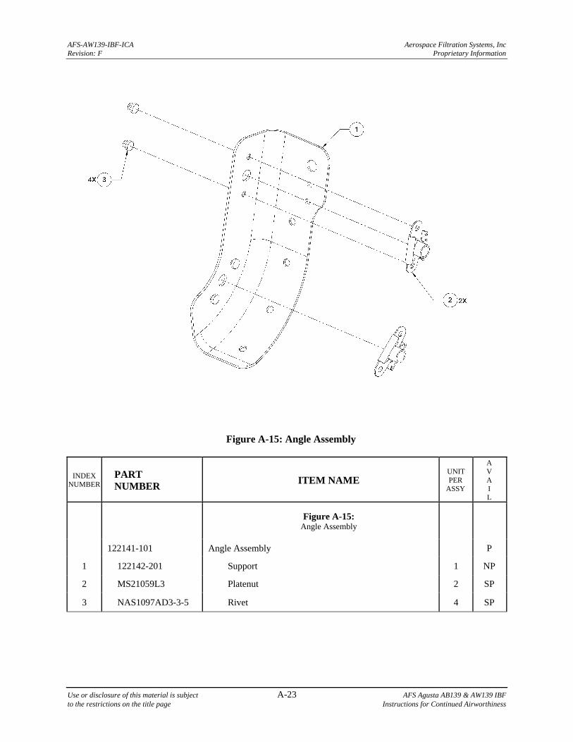
AFS-AW139-IBF-ICA Aerospace Filtration Systems, Inc Revision: F Proprietary Information
Use or disclosure of this material is subject A-23 AFS Agusta AB139 & AW139 IBF to the restrictions on the title page Instructions for Continued Airworthiness
Figure A-15: Angle Assembly
INDEX NUMBER
PART NUMBER
ITEM NAME UNIT PER
ASSY
A V A I L
Figure A-15: Angle Assembly
122141-101 Angle Assembly P
1 122142-201 Support 1 NP
2 MS21059L3 Platenut 2 SP
3 NAS1097AD3-3-5 Rivet 4 SP
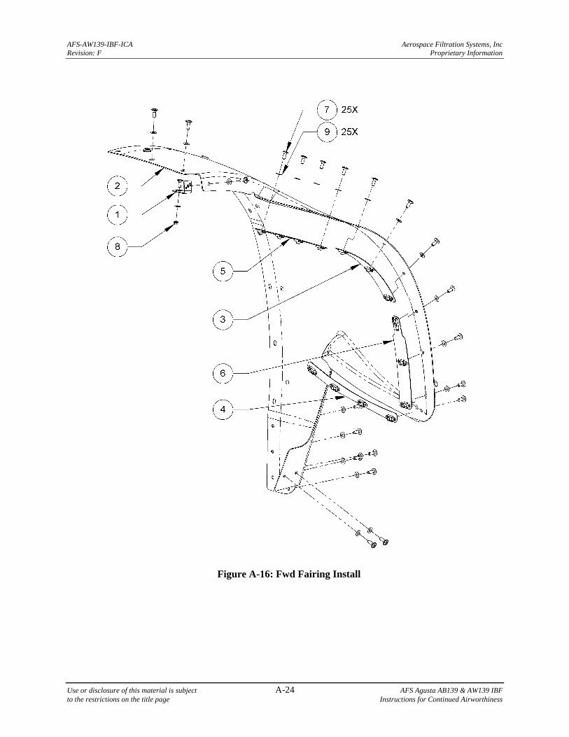
AFS-AW139-IBF-ICA Aerospace Filtration Systems, Inc Revision: F Proprietary Information
Use or disclosure of this material is subject A-24 AFS Agusta AB139 & AW139 IBF to the restrictions on the title page Instructions for Continued Airworthiness
Figure A-16: Fwd Fairing Install
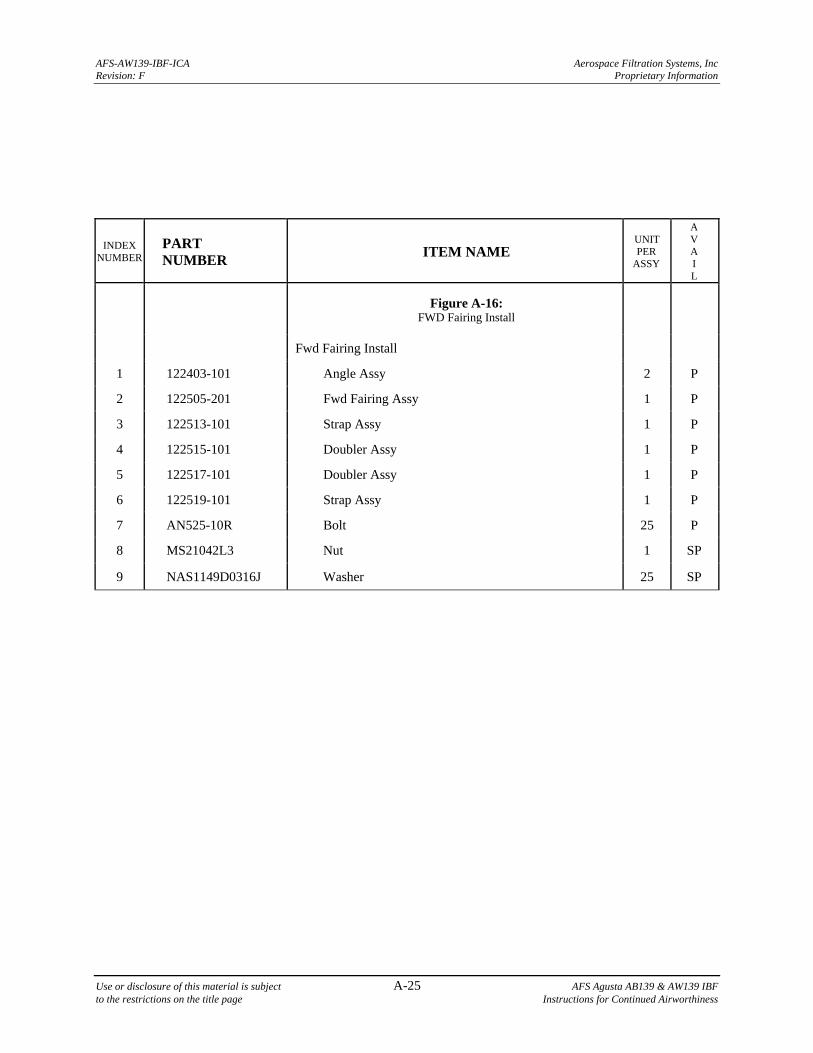
AFS-AW139-IBF-ICA Aerospace Filtration Systems, Inc Revision: F Proprietary Information
Use or disclosure of this material is subject A-25 AFS Agusta AB139 & AW139 IBF to the restrictions on the title page Instructions for Continued Airworthiness
INDEX NUMBER
PART NUMBER
ITEM NAME UNIT PER
ASSY
A V A I L
Figure A-16: FWD Fairing Install
Fwd Fairing Install
1 122403-101 Angle Assy 2 P
2 122505-201 Fwd Fairing Assy 1 P
3 122513-101 Strap Assy 1 P
4 122515-101 Doubler Assy 1 P
5 122517-101 Doubler Assy 1 P
6 122519-101 Strap Assy 1 P
7 AN525-10R Bolt 25 P
8 MS21042L3 Nut 1 SP
9 NAS1149D0316J Washer 25 SP
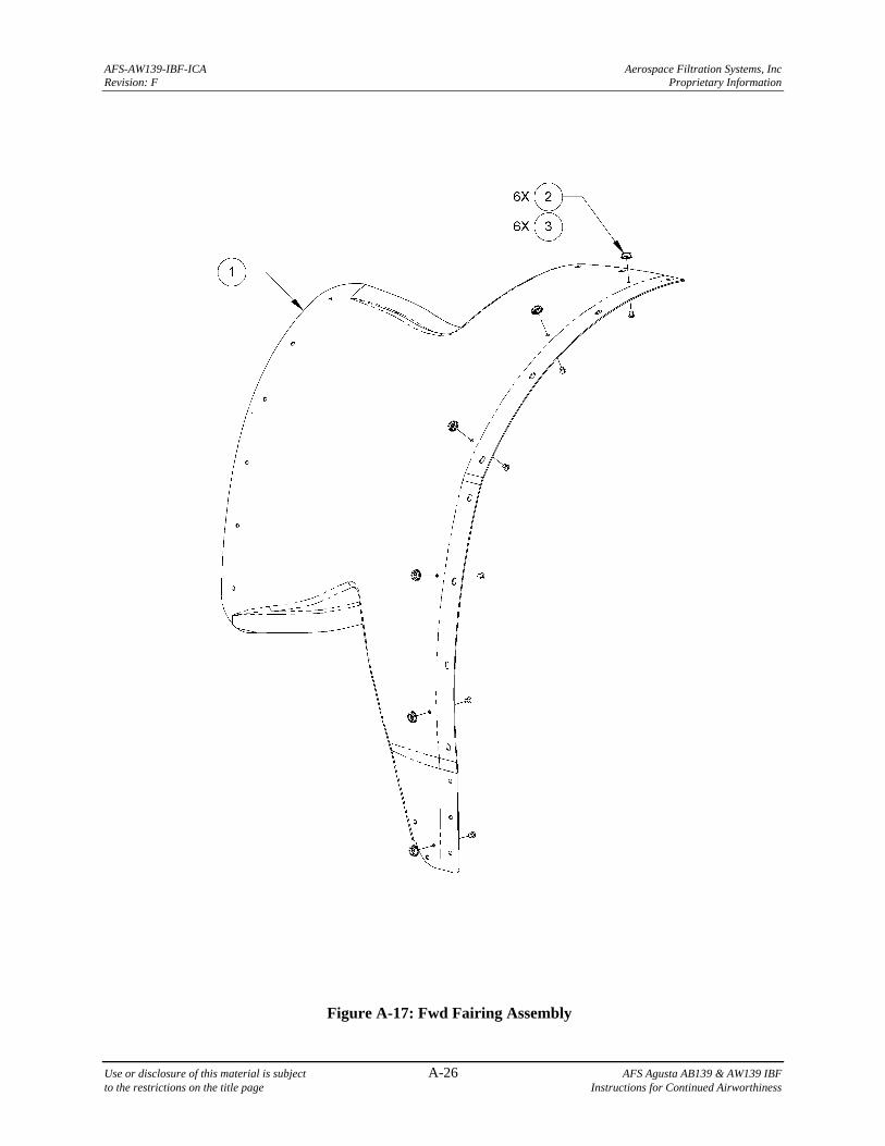
AFS-AW139-IBF-ICA Aerospace Filtration Systems, Inc Revision: F Proprietary Information
Use or disclosure of this material is subject A-26 AFS Agusta AB139 & AW139 IBF to the restrictions on the title page Instructions for Continued Airworthiness
Figure A-17: Fwd Fairing Assembly
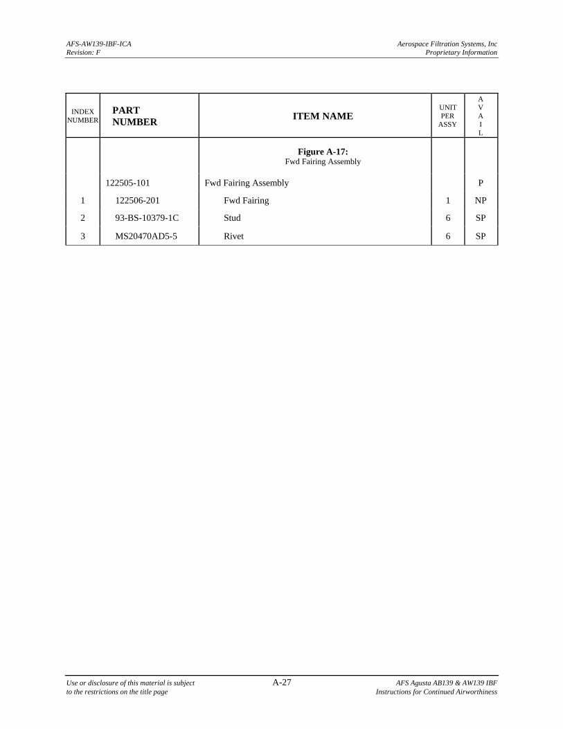
AFS-AW139-IBF-ICA Aerospace Filtration Systems, Inc Revision: F Proprietary Information
Use or disclosure of this material is subject A-27 AFS Agusta AB139 & AW139 IBF to the restrictions on the title page Instructions for Continued Airworthiness
INDEX NUMBER
PART NUMBER
ITEM NAME UNIT PER
ASSY
A V A I L
Figure A-17: Fwd Fairing Assembly
122505-101 Fwd Fairing Assembly P
1 122506-201 Fwd Fairing 1 NP
2 93-BS-10379-1C Stud 6 SP
3 MS20470AD5-5 Rivet 6 SP
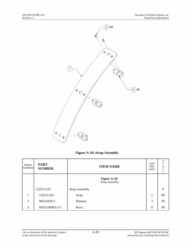
AFS-AW139-IBF-ICA Aerospace Filtration Systems, Inc Revision: F Proprietary Information
Use or disclosure of this material is subject A-28 AFS Agusta AB139 & AW139 IBF to the restrictions on the title page Instructions for Continued Airworthiness
Figure A-18: Strap Assembly
INDEX NUMBER
PART NUMBER
ITEM NAME UNIT PER
ASSY
A V A I L
Figure A-18: Strap Assembly
122513-101 Strap Assembly P
1 122512-201 Strap 1 NP
2 MS21059L3 Platenut 3 SP
3 NAS1200M3-3-5 Rivet 6 SP
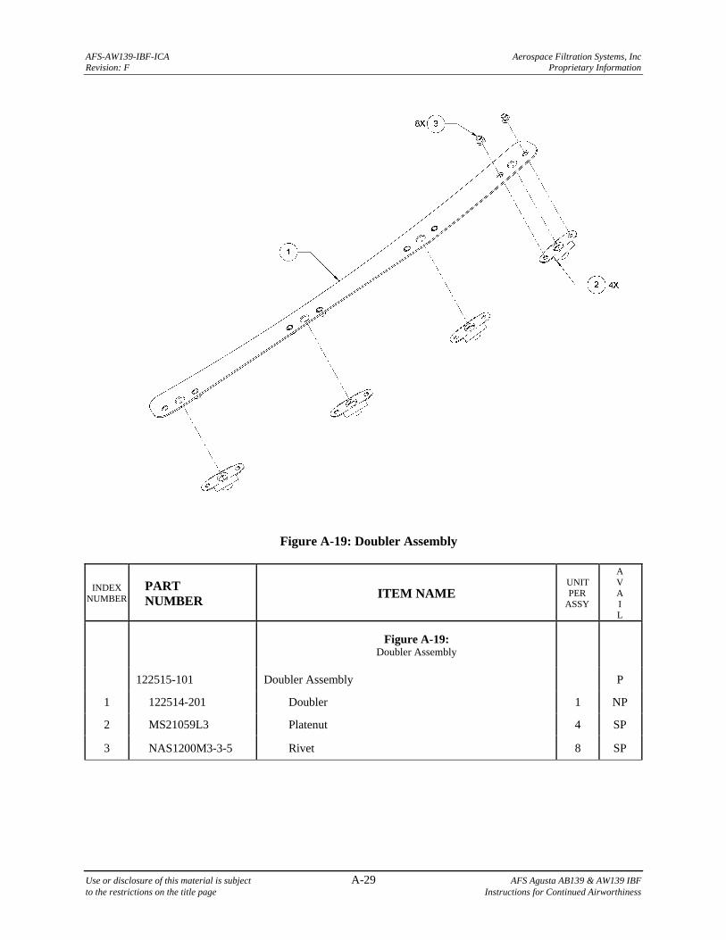
AFS-AW139-IBF-ICA Aerospace Filtration Systems, Inc Revision: F Proprietary Information
Use or disclosure of this material is subject A-29 AFS Agusta AB139 & AW139 IBF to the restrictions on the title page Instructions for Continued Airworthiness
Figure A-19: Doubler Assembly
INDEX NUMBER
PART NUMBER
ITEM NAME UNIT PER
ASSY
A V A I L
Figure A-19: Doubler Assembly
122515-101 Doubler Assembly P
1 122514-201 Doubler 1 NP
2 MS21059L3 Platenut 4 SP
3 NAS1200M3-3-5 Rivet 8 SP
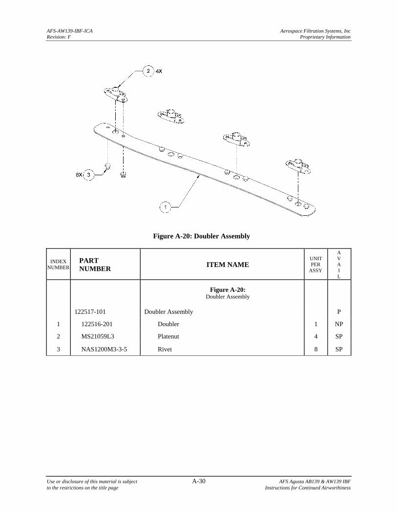
AFS-AW139-IBF-ICA Aerospace Filtration Systems, Inc Revision: F Proprietary Information
Use or disclosure of this material is subject A-30 AFS Agusta AB139 & AW139 IBF to the restrictions on the title page Instructions for Continued Airworthiness
Figure A-20: Doubler Assembly
INDEX NUMBER
PART NUMBER
ITEM NAME UNIT PER
ASSY
A V A I L
Figure A-20: Doubler Assembly
122517-101 Doubler Assembly P
1 122516-201 Doubler 1 NP
2 MS21059L3 Platenut 4 SP
3 NAS1200M3-3-5 Rivet 8 SP
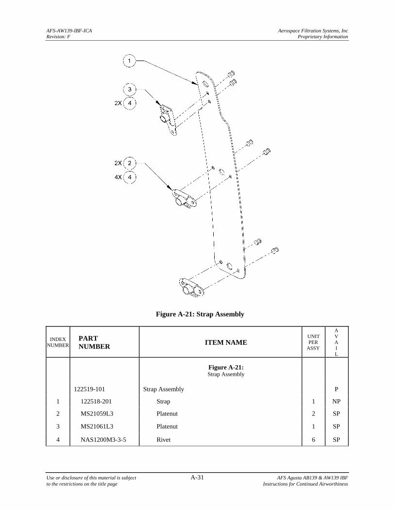
AFS-AW139-IBF-ICA Aerospace Filtration Systems, Inc Revision: F Proprietary Information
Use or disclosure of this material is subject A-31 AFS Agusta AB139 & AW139 IBF to the restrictions on the title page Instructions for Continued Airworthiness
Figure A-21: Strap Assembly
INDEX NUMBER
PART NUMBER
ITEM NAME UNIT PER
ASSY
A V A I L
Figure A-21: Strap Assembly
122519-101 Strap Assembly P
1 122518-201 Strap 1 NP
2 MS21059L3 Platenut 2 SP
3 MS21061L3 Platenut 1 SP
4 NAS1200M3-3-5 Rivet 6 SP

AFS-AW139-IBF-ICA Aerospace Filtration Systems, Inc Revision: F Proprietary Information
Use or disclosure of this material is subject A-32 AFS Agusta AB139 & AW139 IBF to the restrictions on the title page Instructions for Continued Airworthiness
Figure A-22: Angle Assembly
INDEX NUMBER
PART NUMBER
ITEM NAME UNIT PER
ASSY
A V A I L
Figure A-22: Angle Assembly
122403-101 Angle Assembly P
1 122404-201 Angle 1 NP
2 MS21075L3N Platenut 1 SP
3 NAS1097AD3-3-5 Rivet 2 SP
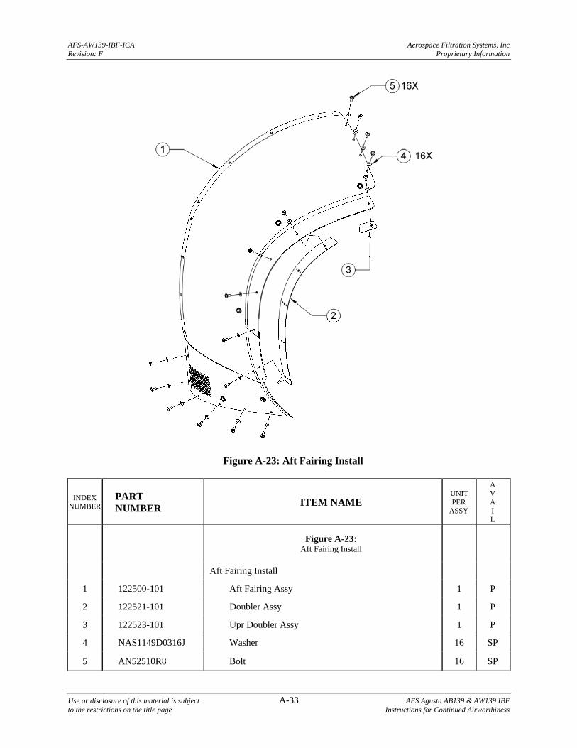
AFS-AW139-IBF-ICA Aerospace Filtration Systems, Inc Revision: F Proprietary Information
Use or disclosure of this material is subject A-33 AFS Agusta AB139 & AW139 IBF to the restrictions on the title page Instructions for Continued Airworthiness
Figure A-23: Aft Fairing Install
INDEX NUMBER
PART NUMBER
ITEM NAME UNIT PER
ASSY
A V A I L
Figure A-23: Aft Fairing Install
Aft Fairing Install
1 122500-101 Aft Fairing Assy 1 P
2 122521-101 Doubler Assy 1 P
3 122523-101 Upr Doubler Assy 1 P
4 NAS1149D0316J Washer 16 SP
5 AN52510R8 Bolt 16 SP
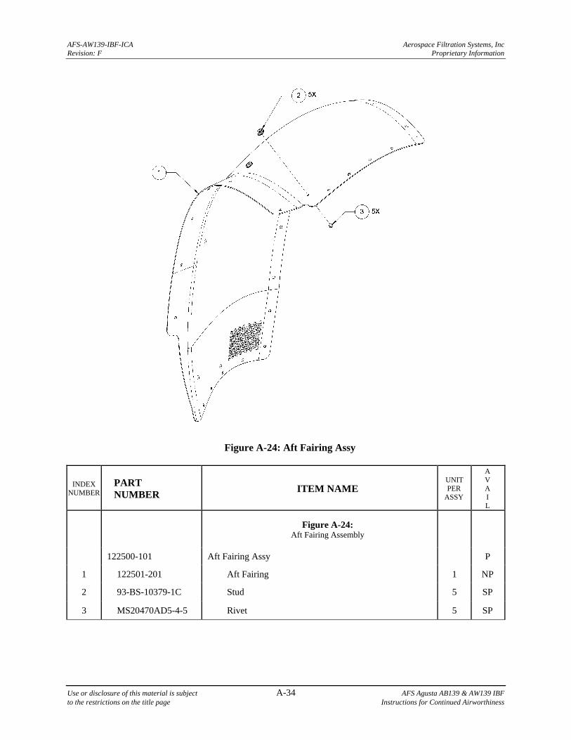
AFS-AW139-IBF-ICA Aerospace Filtration Systems, Inc Revision: F Proprietary Information
Use or disclosure of this material is subject A-34 AFS Agusta AB139 & AW139 IBF to the restrictions on the title page Instructions for Continued Airworthiness
Figure A-24: Aft Fairing Assy
INDEX NUMBER
PART NUMBER
ITEM NAME UNIT PER
ASSY
A V A I L
Figure A-24: Aft Fairing Assembly
122500-101 Aft Fairing Assy P
1 122501-201 Aft Fairing 1 NP
2 93-BS-10379-1C Stud 5 SP
3 MS20470AD5-4-5 Rivet 5 SP
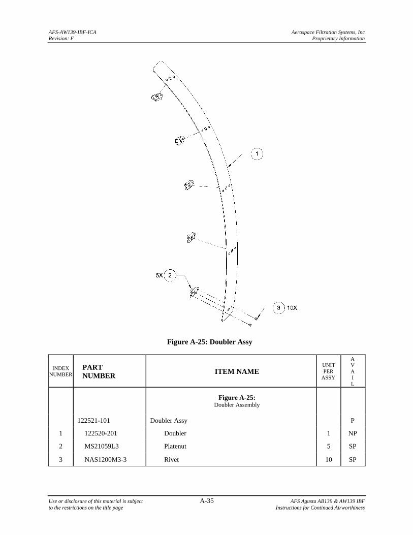
AFS-AW139-IBF-ICA Aerospace Filtration Systems, Inc Revision: F Proprietary Information
Use or disclosure of this material is subject A-35 AFS Agusta AB139 & AW139 IBF to the restrictions on the title page Instructions for Continued Airworthiness
Figure A-25: Doubler Assy
INDEX NUMBER
PART NUMBER
ITEM NAME UNIT PER
ASSY
A V A I L
Figure A-25: Doubler Assembly
122521-101 Doubler Assy P
1 122520-201 Doubler 1 NP
2 MS21059L3 Platenut 5 SP
3 NAS1200M3-3 Rivet 10 SP
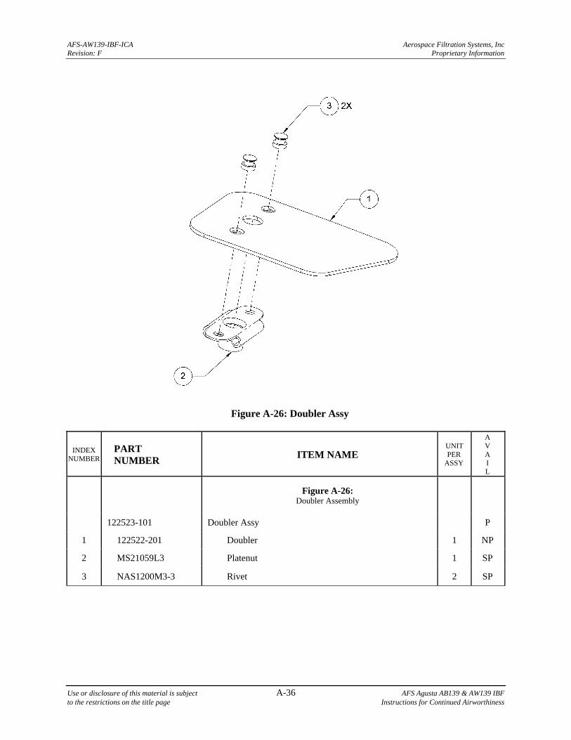
AFS-AW139-IBF-ICA Aerospace Filtration Systems, Inc Revision: F Proprietary Information
Use or disclosure of this material is subject A-36 AFS Agusta AB139 & AW139 IBF to the restrictions on the title page Instructions for Continued Airworthiness
Figure A-26: Doubler Assy
INDEX NUMBER
PART NUMBER
ITEM NAME UNIT PER
ASSY
A V A I L
Figure A-26: Doubler Assembly
122523-101 Doubler Assy P
1 122522-201 Doubler 1 NP
2 MS21059L3 Platenut 1 SP
3 NAS1200M3-3 Rivet 2 SP
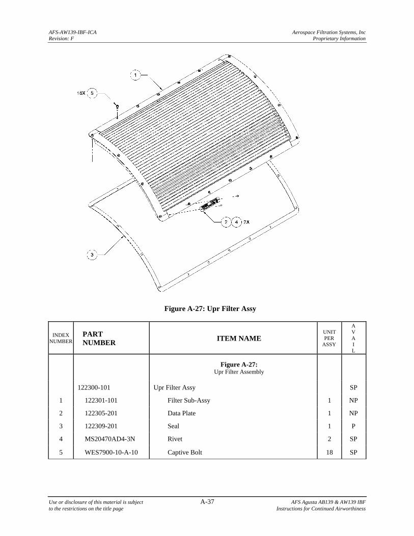
AFS-AW139-IBF-ICA Aerospace Filtration Systems, Inc Revision: F Proprietary Information
Use or disclosure of this material is subject A-37 AFS Agusta AB139 & AW139 IBF to the restrictions on the title page Instructions for Continued Airworthiness
Figure A-27: Upr Filter Assy
INDEX NUMBER
PART NUMBER
ITEM NAME UNIT PER
ASSY
A V A I L
Figure A-27: Upr Filter Assembly
122300-101 Upr Filter Assy SP
1 122301-101 Filter Sub-Assy 1 NP
2 122305-201 Data Plate 1 NP
3 122309-201 Seal 1 P
4 MS20470AD4-3N Rivet 2 SP
5 WES7900-10-A-10 Captive Bolt 18 SP
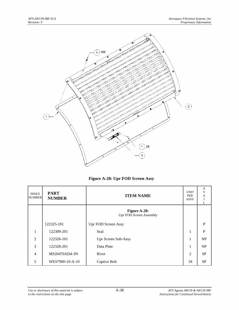
AFS-AW139-IBF-ICA Aerospace Filtration Systems, Inc Revision: F Proprietary Information
Use or disclosure of this material is subject A-38 AFS Agusta AB139 & AW139 IBF to the restrictions on the title page Instructions for Continued Airworthiness
Figure A-28: Upr FOD Screen Assy
INDEX NUMBER
PART NUMBER
ITEM NAME UNIT PER
ASSY
A V A I L
Figure A-28: Upr FOD Screen Assembly
122325-101 Upr FOD Screen Assy P
1 122309-201 Seal 1 P
2 122326-101 Upr Screen Sub-Assy 1 NP
3 122328-201 Data Plate 1 NP
4 MS20470AD4-3N Rivet 2 SP
5 WES7900-10-A-10 Captive Bolt 18 SP
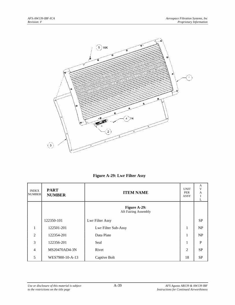
AFS-AW139-IBF-ICA Aerospace Filtration Systems, Inc Revision: F Proprietary Information
Use or disclosure of this material is subject A-39 AFS Agusta AB139 & AW139 IBF to the restrictions on the title page Instructions for Continued Airworthiness
Figure A-29: Lwr Filter Assy
INDEX NUMBER
PART NUMBER
ITEM NAME UNIT PER
ASSY
A V A I L
Figure A-29: Aft Fairing Assembly
122350-101 Lwr Filter Assy SP
1 122501-201 Lwr Filter Sub-Assy 1 NP
2 122354-201 Data Plate 1 NP
3 122356-201 Seal 1 P
4 MS20470AD4-3N Rivet 2 SP
5 WES7900-10-A-13 Captive Bolt 18 SP
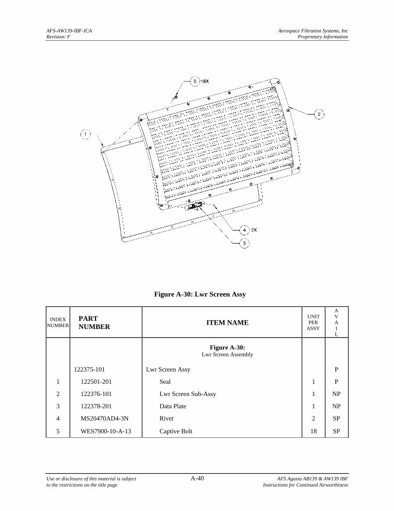
AFS-AW139-IBF-ICA Aerospace Filtration Systems, Inc Revision: F Proprietary Information
Use or disclosure of this material is subject A-40 AFS Agusta AB139 & AW139 IBF to the restrictions on the title page Instructions for Continued Airworthiness
Figure A-30: Lwr Screen Assy
INDEX NUMBER
PART NUMBER
ITEM NAME UNIT PER
ASSY
A V A I L
Figure A-30: Lwr Screen Assembly
122375-101 Lwr Screen Assy P
1 122501-201 Seal 1 P
2 122376-101 Lwr Screen Sub-Assy 1 NP
3 122378-201 Data Plate 1 NP
4 MS20470AD4-3N Rivet 2 SP
5 WES7900-10-A-13 Captive Bolt 18 SP
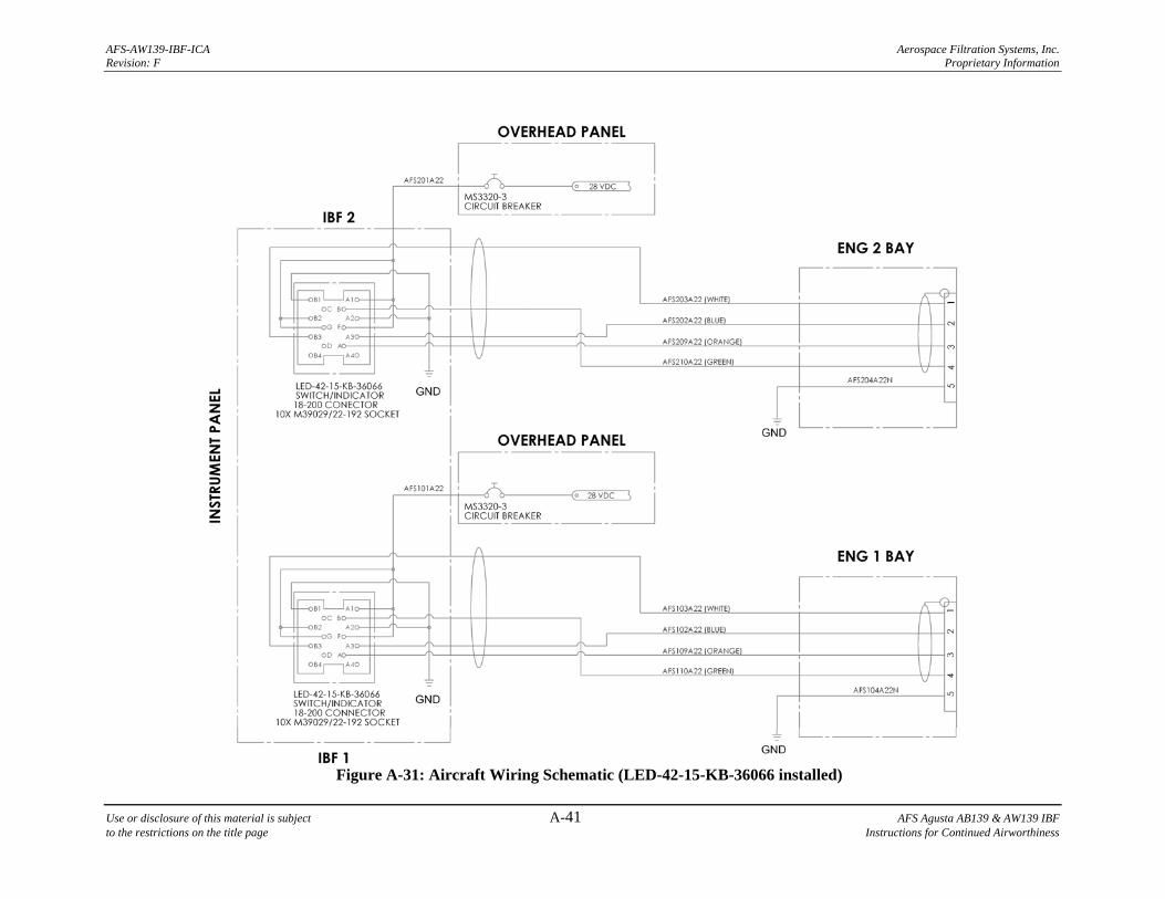
AFS-AW139-IBF-ICA Aerospace Filtration Systems, Inc. Revision: F Proprietary Information
Use or disclosure of this material is subject A-41 AFS Agusta AB139 & AW139 IBF to the restrictions on the title page Instructions for Continued Airworthiness
Figure A-31: Aircraft Wiring Schematic (LED-42-15-KB-36066 installed)
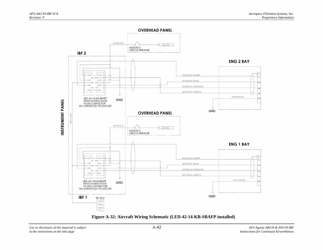
AFS-AW139-IBF-ICA Aerospace Filtration Systems, Inc. Revision: F Proprietary Information
Use or disclosure of this material is subject A-42 AFS Agusta AB139 & AW139 IBF to the restrictions on the title page Instructions for Continued Airworthiness
Figure A-32: Aircraft Wiring Schematic (LED-42-14-KB-SBAFP installed)
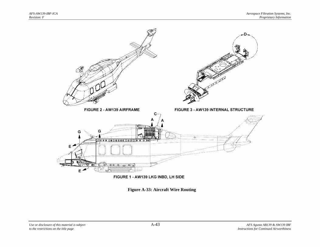
AFS-AW139-IBF-ICA Aerospace Filtration Systems, Inc. Revision: F Proprietary Information
Use or disclosure of this material is subject A-43 AFS Agusta AB139 & AW139 IBF to the restrictions on the title page Instructions for Continued Airworthiness
Figure A-33: Aircraft Wire Routing
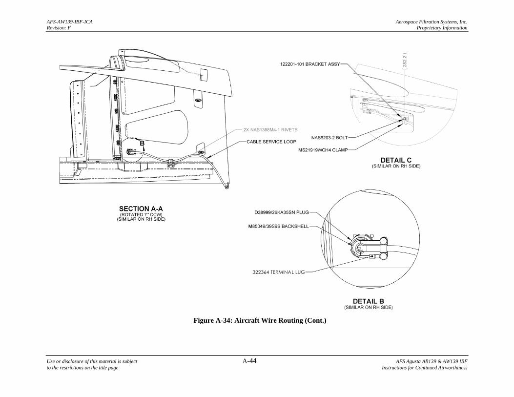
AFS-AW139-IBF-ICA Aerospace Filtration Systems, Inc. Revision: F Proprietary Information
Use or disclosure of this material is subject A-44 AFS Agusta AB139 & AW139 IBF to the restrictions on the title page Instructions for Continued Airworthiness
Figure A-34: Aircraft Wire Routing (Cont.)
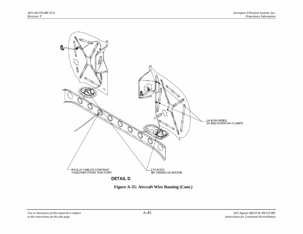
AFS-AW139-IBF-ICA Aerospace Filtration Systems, Inc. Revision: F Proprietary Information
Use or disclosure of this material is subject A-45 AFS Agusta AB139 & AW139 IBF to the restrictions on the title page Instructions for Continued Airworthiness
Figure A-35: Aircraft Wire Routing (Cont.)
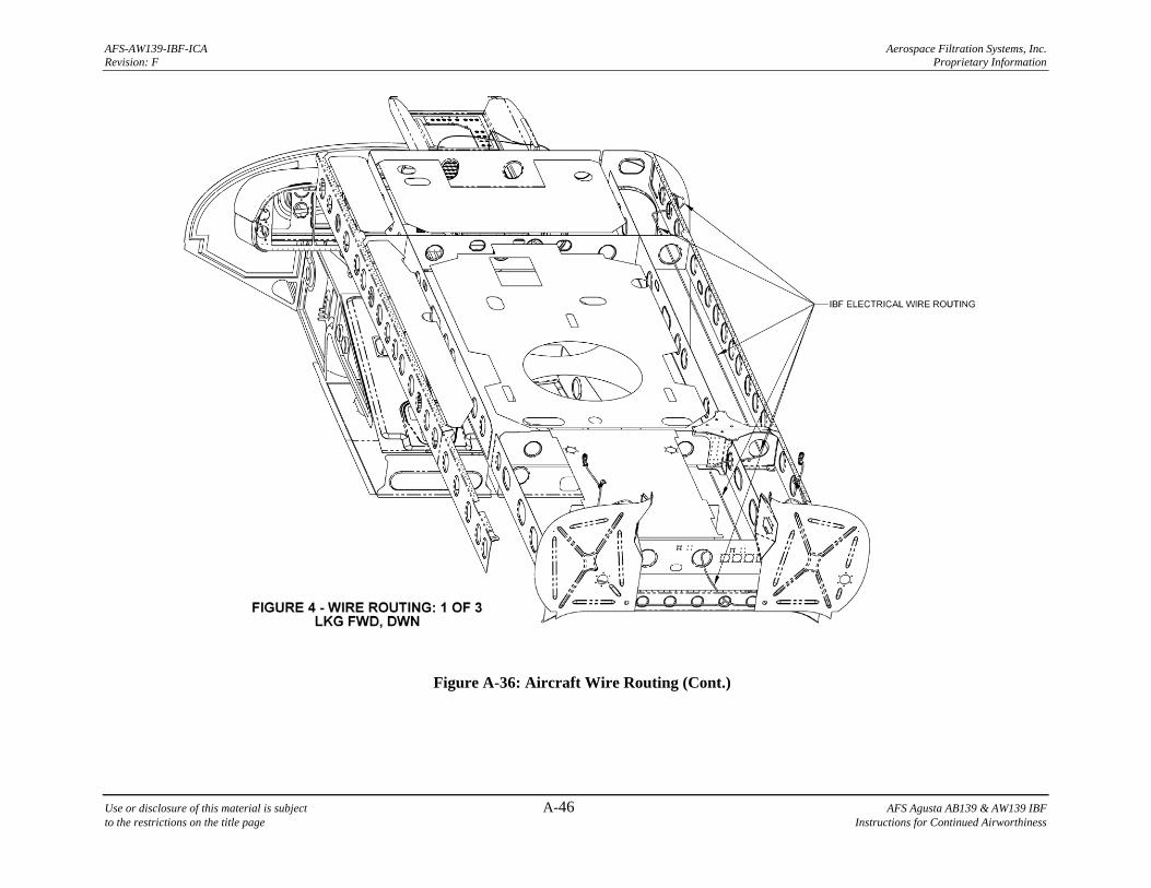
AFS-AW139-IBF-ICA Aerospace Filtration Systems, Inc. Revision: F Proprietary Information
Use or disclosure of this material is subject A-46 AFS Agusta AB139 & AW139 IBF to the restrictions on the title page Instructions for Continued Airworthiness
Figure A-36: Aircraft Wire Routing (Cont.)
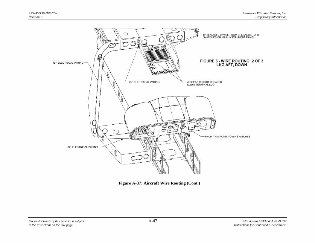
AFS-AW139-IBF-ICA Aerospace Filtration Systems, Inc. Revision: F Proprietary Information
Use or disclosure of this material is subject A-47 AFS Agusta AB139 & AW139 IBF to the restrictions on the title page Instructions for Continued Airworthiness
Figure A-37: Aircraft Wire Routing (Cont.)
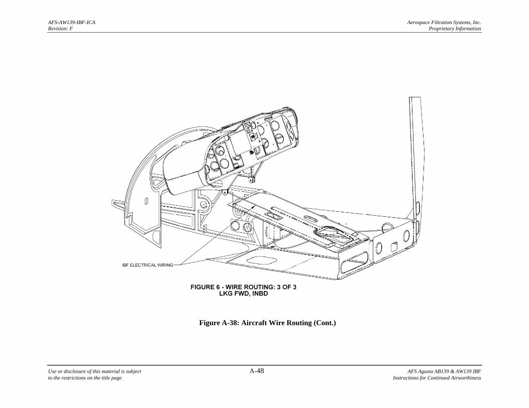
AFS-AW139-IBF-ICA Aerospace Filtration Systems, Inc. Revision: F Proprietary Information
Use or disclosure of this material is subject A-48 AFS Agusta AB139 & AW139 IBF to the restrictions on the title page Instructions for Continued Airworthiness
Figure A-38: Aircraft Wire Routing (Cont.)
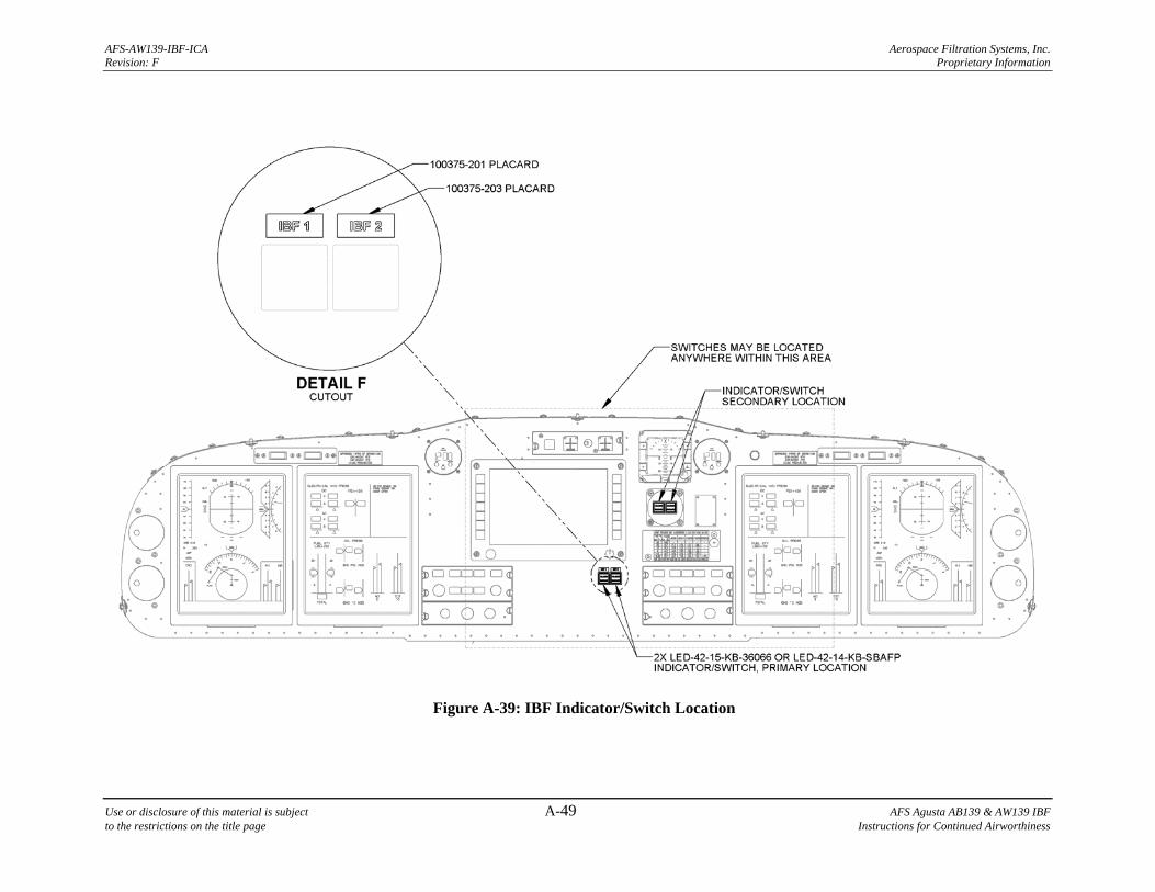
AFS-AW139-IBF-ICA Aerospace Filtration Systems, Inc. Revision: F Proprietary Information
Use or disclosure of this material is subject A-49 AFS Agusta AB139 & AW139 IBF to the restrictions on the title page Instructions for Continued Airworthiness
Figure A-39: IBF Indicator/Switch Location
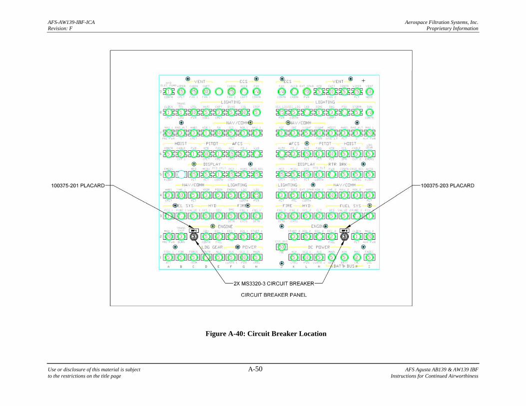
AFS-AW139-IBF-ICA Aerospace Filtration Systems, Inc. Revision: F Proprietary Information
Use or disclosure of this material is subject A-50 AFS Agusta AB139 & AW139 IBF to the restrictions on the title page Instructions for Continued Airworthiness
Figure A-40: Circuit Breaker Location
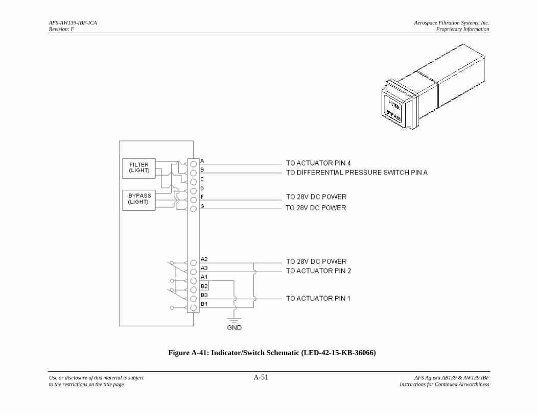
AFS-AW139-IBF-ICA Aerospace Filtration Systems, Inc. Revision: F Proprietary Information
Use or disclosure of this material is subject A-51 AFS Agusta AB139 & AW139 IBF to the restrictions on the title page Instructions for Continued Airworthiness
Figure A-41: Indicator/Switch Schematic (LED-42-15-KB-36066)
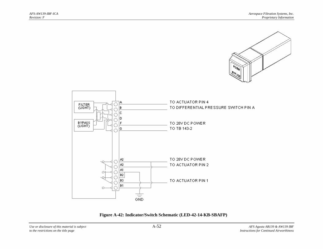
AFS-AW139-IBF-ICA Aerospace Filtration Systems, Inc. Revision: F Proprietary Information
Use or disclosure of this material is subject A-52 AFS Agusta AB139 & AW139 IBF to the restrictions on the title page Instructions for Continued Airworthiness
Figure A-42: Indicator/Switch Schematic (LED-42-14-KB-SBAFP)
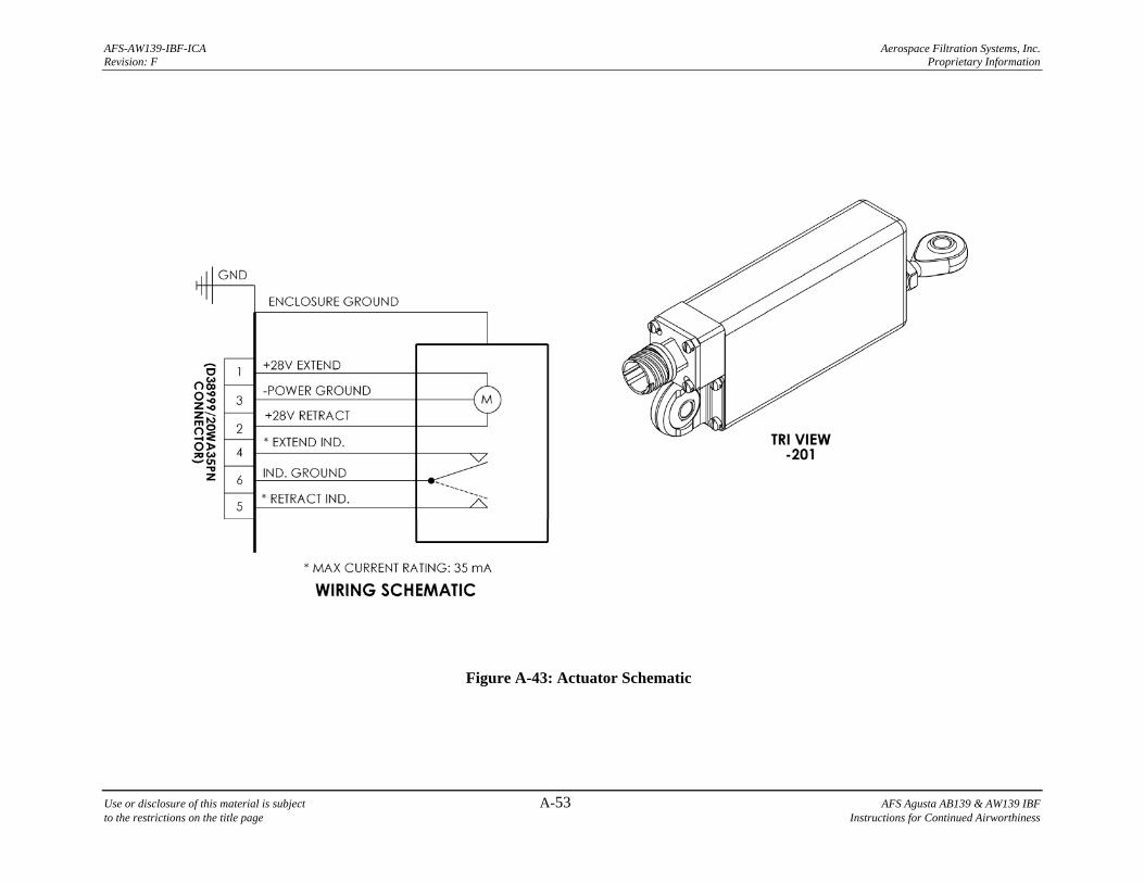
AFS-AW139-IBF-ICA Aerospace Filtration Systems, Inc. Revision: F Proprietary Information
Use or disclosure of this material is subject A-53 AFS Agusta AB139 & AW139 IBF to the restrictions on the title page Instructions for Continued Airworthiness
Figure A-43: Actuator Schematic