Embed Size (px)
Citation preview
Instruction Manual
Thank you for purchasing the Hitachi IJ Printer Model PXR-D.
This printer employs a noncontact, ink-jet method to print onto a print target.
This instruction manual describes the basic operating procedures, maintenance
procedures, and other detailed handling procedures of the Hitachi IJ Printer
Model PXR-D.
If the printer is improperly handled or maintained, it may not operate smoothly
and may become defective or cause an accident. It is therefore essential that
you read this manual to gain a complete understanding of the printer and use it
correctly.
After thoroughly reading the manual, properly store it for future reference.
Model PXR-D
HITACHI Printer
IF you changed the language of screen by mistake,
see the chapter 5.5 "Selecting Languages".
PXRINK JET PRINTER
INK JET PRINTER FOR INDUSTRIAL MARKING
WARNING
Safety Precautions
Pictograph Examples
¡Before using the printer, thoroughly read the following safety precautions for optimum printer use.
¡You should observe the precautions set forth below in order to use the product properly and avoid
endangering or causing damage to you or other persons. For the purpose of clarifying the severity of
injury or damage and likelihood of occurrence, the precautions are classified into two categories,
WARNING and CAUTION, which both describe the hazardous situations that may arise if you ignore
the precautions and perform an incorrect handling or operating procedure. The precautions in these
two categories are both important and must therefore be observed without fail.
CAUTION
WARNING is used to indicate the presence of a hazard which may cause
severe personal injury or death if the warning against performing an
incorrect handling procedure is ignored.
CAUTION is used to indicate the presence of a hazard which may cause
personal injury or property damage if the warning against performing an
incorrect handling procedure is ignored.
¡If the warning in the CAUTION category is ignored, serious results may occur depending on the
situation.
¡After the manual has been read, it must be stored in such a location that all printer operation
personnel can refer to it at all times.
¡ All the instructions set forth in this manual are important and must therefore be observed without
fail.
The △ symbols are used to indicate precautions (including those related to potential hazards andwarnings) to be observed. Detailed information is furnished by a picture within the symbol outline (ashock hazard is indicated by the example shown at left).
The ○ symbols are used to describe prohibited actions. The details of a prohibited action are givenby a picture within or near the symbol outline (the example shown at left dictates that you must keepflames away).
The ● symbols are used to describe required actions. Detailed instructions are given by a picturewithin the symbol outline (the example shown at left dictates that a ground connection must bemade).
( )
Restrictions on Export
User hereby agrees not to export or re-export this product to any end-user who the user has reason to
suspect may utilize the product for the design, development or reproduction of nuclear, chemical or
biochemical weapons.
File management is carried out using eParts made from eSOL.
Safety Precautions (Continued)
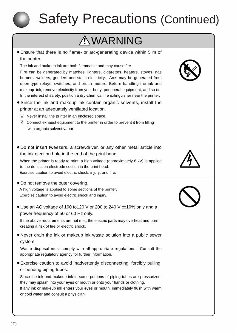
WARNING¡Ensure that there is no flame- or arc-generating device within 5 m of
the printer.
The ink and makeup ink are both flammable and may cause fire.
Fire can be generated by matches, lighters, cigarettes, heaters, stoves, gas
burners, welders, grinders and static electricity. Arcs may be generated from
open-type relays, switches, and brush motors. Before handling the ink and
makeup ink, remove electricity from your body, peripheral equipment, and so on.
In the interest of safety, position a dry-chemical fire extinguisher near the printer.
¡Since the ink and makeup ink contain organic solvents, install the
printer at an adequately ventilated location.
Never install the printer in an enclosed space.
Connect exhaust equipment to the printer in order to prevent it from filling
with organic solvent vapor.
¡Do not insert tweezers, a screwdriver, or any other metal article into
the ink ejection hole in the end of the print head.
When the printer is ready to print, a high voltage (approximately 6 kV) is applied
to the deflection electrode section in the print head.
Exercise caution to avoid electric shock, injury, and fire.
¡Do not remove the outer covering.A high voltage is applied to some sections of the printer.
Exercise caution to avoid electric shock and injury.
¡Use an AC voltage of 100 to120 V or 200 to 240 V ±10% only and a
power frequency of 50 or 60 Hz only.
If the above requirements are not met, the electric parts may overheat and burn,
creating a risk of fire or electric shock.
¡Never drain the ink or makeup ink waste solution into a public sewer
system.
Waste disposal must comply with all appropriate regulations. Consult the
appropriate regulatory agency for further information.
¡Exercise caution to avoid inadvertently disconnecting, forcibly pulling,
or bending piping tubes.
Since the ink and makeup ink in some portions of piping tubes are pressurized,
they may splash into your eyes or mouth or onto your hands or clothing.
If any ink or makeup ink enters your eyes or mouth, immediately flush with warm
or cold water and consult a physician.
2
1
( )
WARNING
Safety Precautions (Continued)
¡ While the printer is operating, do not look into the ink ejection hole in
the end of the print head.
Ink or makeup ink may enter your eyes or mouth or soil your hands or clothing.
If any ink or makeup ink enters your eyes or mouth, immediately flush with warm
or cold water and consult a physician.
¡Ensure that no welding operations are performed within 5 m of the
printer.The welding current may flow to the control section in the printer and cause a
circuit board or printer malfunction. Also, the flame generated by welding may
cause a fire.
¡Before servicing the printer, be sure to stop the ink ejection.
Because ink or makeup ink may splash into your eyes or mouth or onto your
hands or clothing. If any ink or makeup ink enters your eyes or mouth,
immediately flush with warm or cold water and consult a physician.
¡If an earthquake, fire, or other emergency occurs while the printer is
engaged in printing or just turned on, press the ON/OFF power switch
to turn off the power.
¡The printer must be managed in compliance with all appropriate
regulations.
Read and understand the appropriate Material Safety Data Sheet (MSDS) before
using any ink or makeup ink.
¡Only use Hitachi-approved consumables and periodic replacement
parts.
Using products that are not designated by Hitachi may lead to malfunction or
failure. Such malfunction or failure will not be covered by the warranty.
¡Warning for Mercury
Hg -- THE LAMP IN THIS PRODUCT CONTAINS MERCURY. RECYCLE OR
DISPOSE OF ACCORDING TO APPLICABLE ENVIRONMENTAL LAWS.
For Recycling and Disposal information, contact your government agency, the
Electronic Industries Alliance at www.eiae.org, and/or www.lamprecycle.org (in
the US), or the Electronic Product Stewardship Canada at www.epsc.ca (in
Canada). For more information, call 1-800-HITACHI (1-800-448-2244) (in the
US).
( )
WARNING¡When charging a refill of ink or makeup ink, exchanging ink, or otherwise
handling ink or makeup ink, take enough care not to spill ink or makeup ink. Ifyou spill any ink or makeup ink by mistake, wipe it off neatly and promptly withwiping paper or something similar. Do not close the maintenance cover until youmake sure that the portion you have just wiped is completely dry. You must pay particular attention when you have spilled ink or makeup ink insidethe printer and it is not completely dry. Why? Because vapors of ink or makeupink will stay inside the printer and may catch on or cause a fire.
If you find it hard to wipe the printer when energized, stop it with the maintenance coveropen. Power it down, then wipe it off again.
¡If you wish to clean the casing of the printer with wiping paper impregnated withmakeup ink, be sure to do so with the power down.
Attempting to clean it when energized will cause makeup ink or vapors of makeup ink toenter the printer, possibly catching on or causing a fire. When the cleaning is over, open the maintenance cover and make sure that no makeup inkhas entered and no vapors stay inside.
¡Should you find a leak of ink or makeup ink inside the printer while the printer isrunning or being maintained, wipe it off promptly with wiping paper or somethingsimilar. Then, with the maintenance cover open, stop the printer, power it down,and repair the leak.
A continued run with a leak of ink or makeup ink will cause an anomaly, resulting inabnormal printing. Ink and makeup ink are flammable. They may therefore catch on or cause a fire.
¡If you wish to receive ink particles in a beaker, for a printing test for example,use an electrically conductive beaker and connect the beaker securely to theground. Do not let the tip of the printing head enter the beaker.
Ink particles used for printing are electrically charged. An ungrounded beaker has agradually rising charge, possibly catching on or causing a fire.
Safety Precautions (Continued)
( )

Safety Precautions (Continued)
CAUTION¡Only persons who have completed an operator training course for
Hitachi IJP can operate and service the printer.If the printer is operated or serviced incorrectly, it may malfunction or break
down.
¡Do not attempt to make repairs for any purpose other than operation or
maintenance.
¡Since the ink and makeup ink contain organic solvents, observe the
following handling precautions.Secure adequate space for the ink/makeup ink handling area and printer
installation site. At least 200 m3 must be provided per print head.
Ensure that adequate ventilation is provided.
When handling the ink or makeup ink, wear protective gloves and safety
goggles to avoid direct skin contact. If the ink or makeup ink comes into
contact with skin, wash thoroughly with soap and warm or cold water.
When transferring the ink or makeup ink to or from a bottle, exercise
caution to prevent it coming into contact with the printer or surrounding
articles.
If there is any spillage, immediately wipe it clean using a cloth moistened
with ethyl alcohol.Notice that there is a possibility that a cap and a content may fly with inner
pressure when opening the container of ink and a solvent.
Please open a cap of container an even place.
3
2
1
4
5
( )
¡Ink and makeup ink must be stored as flammable liquids. Storage
must comply with local regulatory requirements. Consult the
appropriate regulatory agency for further information.
¡If extraneous noise enters the printer, it may malfunction or break
down.For maximum noise immunity, observe the following installation and wiring
precautions.
Ensure that 100 to 120 VAC or 200 to 240 VAC power cables are not
bundled with other power supply cables.
Insulate the printer main body and print head so that they do not come
into direct contact with the conveyor or other devices.
If the employed print target detector is housed in a metal case, use a
plastic mounting brace for the purpose of insulating the detector from the
conveyor and other devices.
Be sure that the print target detector wiring is not bundled together with
other power supply cables.
Safety Precautions (Continued)
CAUTION¡Ensure that all electrical wiring, connections and grounding comply
with applicable codes. Properly connect the printer to its dedicated
ground.
Complete the above procedure to avoid electrical shock hazards.
3
2
1
4
FCC NoticeThis equipment has been tested and found to comply with the limits for a Class A digital device,pursuant to part 15 of the FCC Rules. These limits are designed to provide reasonable protectionagainst harmful interference when the equipment is operated in a commercial environment.
This equipment generates, uses, and can radiate radio frequency energy and, if not installed and used inaccordance with the instruction manual, may cause harmful interference to radio communications.Operation of this equipment in a residential area is likely to cause harmful interference in which case theuser will be required to correct the interference at his own expense.
( )
Contents1. Overview ................................................................................1-1
1.1 Item Delivered ..........................................................................................1-11.2 Usage Precautions....................................................................................1-3
1.2.1 Notes on ink and makeup ink ........................................................................1-3
1.2.2 IJ printer long-term shutdown........................................................................1-8
1.2.3 Print head cleaning ......................................................................................1-9
1.2.4 Shutdown (no-cleaning stop) ........................................................................1-11
1.2.5 Cautions on operating time when printer is in service ..................................1-12
1.2.6 Print head air purge ......................................................................................1-13
1.2.7 Heating of ink ................................................................................................1-14
1.2.8 Ink concentration control ..............................................................................1-14
1.2.9 Gutter cleaning..............................................................................................1-15
1.2.10 Protection Sheet for touch panel ..................................................................1-15
1.3 Component Names and Functions ..........................................................1-161.3.1 External views ..............................................................................................1-16
1.3.2 Main body internal parts arrangement ..........................................................1-17
1.3.3 Print head ....................................................................................................1-18
1.4 Installing Precautions ..............................................................................1-191.5 Connection of signals..............................................................................1-22
1.5.1 Wiring Precautions........................................................................................1-22
1.5.2 Overview ......................................................................................................1-24
1.5.3 Connection of various signal ........................................................................1-28
1.5.4 Using the Ready Output Selector Switch ......................................................1-44
2. Basic Operating Procedures ..................................................2-12.1 Startup ..................................................................................................2-1
2.1.1 Starting an operation ....................................................................................2-1
2.1.2 If a fault occurs at the beginning of an operation ..........................................2-4
2.1.3 Operations for Modifying the Setting Contents ..............................................2-7
2.2 Shutdown ..................................................................................................2-102.3 Operating Scheme ..................................................................................2-12
2.3.1 Operating Scheme ........................................................................................2-12
2.3.2 Status ..........................................................................................................2-13
3. Editing Print Data and Printing ..............................................3-13.1 Setting Print Lines ....................................................................................3-33.2 Setting Print Format ..................................................................................3-63.3 Printing Characters ..................................................................................3-12
3.3.1 Printing fixed characters................................................................................3-12
3.3.2 Printing dedicated characters
(when KANA and dedicated characters can be input) ....................3-14
Printing special characters (when special characters can be input) ..............3-15
3.3.3 Printing calendar characters..........................................................................3-17
3.3.4 Printing the characters indicating the number of elapsed days......................3-19
3.3.5 Printing month with 3 alphabet characters ....................................................3-21
3.3.6 Printing week number ..................................................................................3-24
3.3.7 Printing day of the week................................................................................3-26
●Contents 1
3.3.8 Printing count characters ..............................................................................3-28
3.3.9 Printing Arabic characters ............................................................................3-34
3.4 Setting Character Height and Character Orientation ............................3-353.5 Setting Repeat Printing ........................................................................3-393.6 Printing Future Date and Time ..............................................................3-413.7 Printing with Date/Time Changed to Other Characters ..........................3-443.8 Saving Edited Print Data ........................................................................3-473.9 Recalling Saved Data ............................................................................3-483.10 Setting high-speed printing ....................................................................3-493.11 Printing shift code....................................................................................3-543.12 Renewing print contents at a fixed period ..............................................3-58
4. Setting the Operating Environment ........................................4-14.1 Managing the Operations..........................................................................4-14.2 Setting the User Environment ..................................................................4-44.3 Setting the Date and Time ........................................................................4-94.4 Setting the Password ..............................................................................4-114.5 Controlling the Executable Functions ......................................................4-134.6 Confirming the Registered Software........................................................4-164.7 Touch screen Setup ................................................................................4-174.8 Printing Without Entering Sensor Signals ................................................4-19
5. Auxiliary Function ..................................................................5-15.1 Managing Created Print Data ..................................................................5-1
5.1.1 Changing the message number ....................................................................5-1
5.1.2 Deleting stored data......................................................................................5-4
5.1.3 Changing a message name ..........................................................................5-6
5.2 Creating a User Pattern ............................................................................5-85.2.1 Saving a user pattern ....................................................................................5-8
5.2.2 Recalling a user pattern ................................................................................5-13
5.3 Copying User Data on a Memory Card ....................................................5-16
5.4 Calibrating the Touch Screen Coordinates ..............................................5-20
5.5 Selecting Languages ................................................................................5-22
5.6 Editing Standard Character Patterns ........................................................5-24
5.7 Editing/registering data that is different from that being printed................5-27
6. Communication ......................................................................6-16.1 Overview ..................................................................................................6-16.2 Setting Communication Environment........................................................6-2
6.2.1 Setting Communication Environment ............................................................6-2
6.2.2 Transmission Specifications..........................................................................6-4
6.3 Standard Communication Functions ........................................................6-56.3.1 Printings Transmission..................................................................................6-5
6.3.2 Print Data Recall / Transmission ..................................................................6-6
6.3.3 Print Condition Transmission ........................................................................6-7
6.3.4 User Pattern Character Transmission ..........................................................6-9
6.3.5 Calendar Character Transmission ................................................................6-10
6.3.6 Calendar Conditions Transmission ..............................................................6-11
6.3.7 On-line/Off-line Transmission ......................................................................6-12
2 ●Contents
6.3.8 Current Time Output Transmission ..............................................................6-13
6.3.9 Count Character Transmission......................................................................6-14
6.3.10 Count Conditions Transmission ....................................................................6-16
6.4 Transmission Sequences..........................................................................6-186.4.1 Common Transmission Sequences ..............................................................6-18
6.4.2 Printings Transmission..................................................................................6-20
6.4.3 Print Data Recall / Transmission ..................................................................6-21
6.4.4 Print Condition Transmission ........................................................................6-22
6.4.5 User Pattern Character Transmission ..........................................................6-27
6.4.6 Code Tables ................................................................................................6-32
6.4.7 Header Table ..............................................................................................6-38
6.4.8 Character Size Code Table for User Patternon Character Transmission ......6-39
6.4.9 Calendar Character Transmission Procedure ..............................................6-39
6.4.10 Calendar Conditions Transmission Procedure ............................................6-40
6.4.11 On-line/Off-line Transmission Procedure ....................................................6-40
6.4.12 Current Time Output Transmission Procedure ............................................6-41
6.4.13 Count Character Transmission Procedure ....................................................6-41
6.4.14 Count Conditions Transmission Procedure ..................................................6-41
6.5 Communication Timing ............................................................................6-436.5.1 Signal Timimg ..............................................................................................6-43
6.5.2 Response Time ............................................................................................6-47
6.6 Communication Monitor Function ............................................................6-506.7 Warning Messages ..................................................................................6-516.8 Precautions ..............................................................................................6-53
6.8.1 Notes on product speed matching Feature Use ..........................................6-53
6.8.2 Notes on Print Condition Transmission ........................................................6-53
7. Circulation System Operating and Adjustment Procedures 7-17.1 Using the Circulation Control Screen ....................................................7-27.2 Details of Circulation Control ................................................................7-57.3 Ink Replenishment ................................................................................7-67.4 Makeup ink Replenishment ..................................................................7-77.5 Ink Replacement....................................................................................7-87.6 Correcting a Bent Ink Stream and Clogged Nozzle ..............................7-15
7.6.1 Nozzle backwash............................................................................................7-15
7.6.2 Disassembling and cleaning the orifice plate ................................................7-16
7.7 Adjusting the Ink Stream Position........................................................7-197.8 Cleaning the Gutter ............................................................................7-217.9 Ink Filter Replacement ........................................................................7-227.10 Recovery Filter Replacement ..............................................................7-297.11 Circulation Filter Replacement ............................................................7-317.12 Pressure Adjustment ..........................................................................7-327.13 Excitation Setting Adjustment ..............................................................7-347.14 Ink Drop Generation Status Checkout Procedure................................7-387.15 Long-term Shutdown ..........................................................................7-40
7.15.1 Process to be performed prior to long-term shutdown..................................7-40
7.15.2 Startup process to be performed after long-term shutdown ........................7-43
7.16 Draining the Ink from the Main Ink Tank ..............................................7-45
●Contents 3
8. If a Warning Condition/Fault Occurs ....................................8-18.1 Indications Given When a Warning Condition/Fault Occurs ..................8-18.2 On-screen Message Descriptions ..........................................................8-3
8.2.1 Fault messages..............................................................................................8-3
8.2.2 Warning messages ........................................................................................8-7
8.2.3 Other messages ............................................................................................8-8
8.3 Confirming the Warning Condition and Fault Occurrences ......................8-98.4 Remedial Action to Be Taken in the Event of a Printing Failure................8-10
9. Troubleshooting Guide ........................................................9-1
10. Emergency Procedures ........................................................10-1
11. Specifications........................................................................11-111.1 Printer Specifications ..............................................................................11-111.2 Ink Specifications ..................................................................................11-2
12.Maintenance ..........................................................................12-1
13. Schematic Diagrams ............................................................13-113.1 Outside Dimensions ..............................................................................13-113.2 Electrical Connection Diagram ..............................................................13-513.3 Circulation System Diagram ..................................................................13-6
14.Appendix................................................................................14-1●Terms and definitions ..................................................................................14-1●Index ............................................................................................................14-7
4 ●Contents
● Item Delivered 1-1
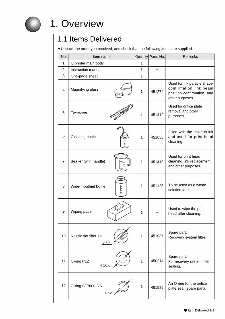
1. Overview1.1 Items Delivered
IJ printer main body
Instruction manual
One-page sheet
Magnifying glass
Tweezers
Cleaning bottle
Beaker (with handle)
Wide-mouthed bottle
Wiping paper
Nozzle flat filter 75
O-ring P12
O-ring SF7000-5.6
1
2
3
4
5
6
7
8
9
10
11
12
RemarksItem name Quantity
¡Unpack the order you received, and check that the following items are supplied.
Parts No.No.
-
-
-
451274
451412
451058
451410
451126
-
451037
450214
451589
1
1
1
1
1
1
1
1
1
1
1
1
Used for ink particle shape confirmation, ink beamposition confirmation, andother purposes.
Used for orifice plateremoval and otherpurposes.
Filled with the makeup inkand used for print headcleaning.
Used for print headcleaning, ink replacement,and other purposes.
To be used as a wastesolution tank.
Used to wipe the printhead after cleaning.
Spare part. Recovery system filter.
Spare part. For recovery system filtersealing.
An O ring for the orificeplate seal (spare part).
φ16
φ16.6
φ7.2

1-2● Item Delivered
Cable seal
Cable clamp
Vinyl bag with fastener
Drainage tube
13
14
15
16
RemarksItem name Quantity Parts No.No.
-
-
-
451676
3
1
1
1
For externalcommunication cablesealing.
Cable clamp
�Nozzle rubber seal
One-page sheet
Used for storage of One-pagesheet and nozzle rubber seal.
If you order items that attached with the main body, tell up their item name and parts No..
Used for ink replacementand filter replacement.

3 months6 months
● Usage Precautions 1-3
Approximate elapsed days
JP-K60
JP-K33
JP-K28
JP-B27JP-R27
1.2 Usage Precautions
(1) Ink and makeup ink replenishmentThe printer employs an automatic ink/makeup ink replenishment system. While the printer is operated, the ink reservoir automatically supplies the ink and the makeup ink reservoir automatically supplies the makeup ink to the ink main tank at regular intervals. If the ink or makeup ink replenisher level is too low,an alarm is issued. In such an instance, effect replenishment without delay.(For the replenishment procedures, see Section 7.3, Ink Replenishment , and Section 7.4, Makeup ink Replenishment.)
(2) Ink periodic replacementFor the replacement procedure, see Section 7.5, Ink Replacement.¡While the IJ printer ink circulates for operations, it reacts with atmospheric air
elements and deteriorates with time. Therefore, it needs periodic replacement. The table below furnishes a guide for determining the proper replacement intervals. However, since the proper replacement intervals vary with the printer operating environmental conditions (temperature, humidity, dust, etc.), determine the best replacement intervals in accordance with the obtained printings, and replace all ink within the printer with new ink.
1.2.1 Notes on ink and makeup ink
Ink type
JP-K26
Replacement intervals (operating hours or elapsed days whichever comes earlier)
Approximate operating hours
600 to 1200 hours 6 months
600 to 1200 hours 6 months
JP-K27 600 to 1200 hours 6 months
JP-K31A 600 to 1200 hours 6 months600 to 1200 hours 6 months
¡What is makeup ink?The makeup ink servesas the replenisherthat makes up for aconstituent loss dueto ink evaporationduring ink ejection. It is also used as acleaning solution.
600 to 1200 hours 6 months
600 to 1200 hours 6 monthsJP-Y37 600 to 1200 hours 6 months
JP-K62
JP-T64JP-F63
JP-K65
JP-K61
JP-K67
300 to 600 hours300 to 600 hours
600 to 1200 hours300 to 600 hours300 to 600 hours
200 hours
600 to 1200 hours
3 months3 months
6 months3 months
1 monthsJP-R65 200 hours 1 months
3 months
6 months
JP-G27 600 to 1200 hours 6 months
JP-K68 300 to 600 hoursJP-K69 600 to 1200 hoursJP-K70 600 to 1200 hours 6 monthsJP-T71 600 to 1200 hours 6 monthsJP-K72 600 to 1200 hours 6 monthsJP-T75 600 to 1200 hours 6 monthsJP-R76 600 to 1200 hours 6 monthsJP-K84 600 to 1200 hours 6 monthsJP-K77 300 to 600 hours 3 monthsJP-E78 300 to 600 hours 3 monthsJP-F80 600 to 1200 hours 6 monthsJP-K81 600 to 1200 hours 6 monthsJP-B82 600 to 1200 hours 6 monthsJP-K86 600 to 1200 hours 6 monthsJP-K87 600 to 1200 hours 6 months
The ink which you can use differs with areas.Please confirm ink which you can use to each area's distributors.
Notice
1-4● Usage Precautions
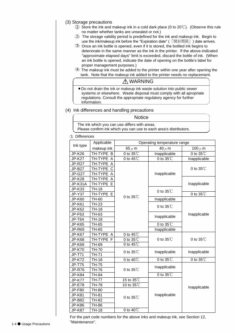
(3) Storage precautionsStore the ink and makeup ink in a cold dark place (0 to 20℃). (Observe this rule no matter whether tanks are unsealed or not.)The storage validity period is predefined for the ink and makeup ink. Begin to use the ink/makeup ink before the "Expiration date" (「開封期限」) date arrives.Once an ink bottle is opened, even if it is stored, the bottled ink begins to deteriorate in the same manner as the ink in the printer. If the above-indicated "approximate elapsed days" limit is exceeded, discard the bottle of ink. (When an ink bottle is opened, indicate the date of opening on the bottle's label for proper management purposes.)The makeup ink must be added to the printer within one year after opening the tank. Note that the makeup ink added to the printer needs no replacement.
1
2
3
4
The ink which you can use differs with areas.Please confirm ink which you can use to each area's distributors.
Notice
¡Do not drain the ink or makeup ink waste solution into public sewersystems or elsewhere. Waste disposal must comply with all apropriateregulations. Consult the appropriate regulatory agency for furtherinformation.
WARNING
(4) Ink differences and handling precautions
Differences1
For the part code numbers for the above inks and makeup ink, see Section 12,"Maintenance".
Ink typeApplicable
makeup ink
Operating temperature range
65μm 40μm JP-K26 TH-TYPE B 0 to 35℃ Inapplicable
100μm 0 to 35℃
Inapplicable
0 to 35℃
Inapplicable
0 to 35℃
Inapplicable
JP-K27 TH-TYPE A 0 to 45℃ 0 to 35℃JP-R27 TH-TYPE A
0 to 35℃
Inapplicable
0 to 35℃
Inapplicable
0 to 35℃
Inapplicable
0 to 35℃Inapplicable
0 to 35℃ 0 to 35℃
Inapplicable
0 to 35℃
JP-B27 TH-TYPE CJP-G27 TH-TYPE AJP-K28 TH-TYPE AJP-K31A TH-TYPE EJP-K33 TH-18JP-Y37 TH-TYPE EJP-K60 TH-60JP-K61 TH-23JP-K62 TH-18JP-F63 TH-63JP-T64 TH-18JP-K65 TH-65JP-R65 TH-65JP-K67 TH-TYPE AJP-K68 TH-TYPE FJP-K69 TH-69JP-K70 TH-70JP-T71 TH-71JP-K72 TH-18JP-T75 TH-75JP-R76 TH-76JP-K84 TH-84JP-K77 TH-77JP-E78 TH-78JP-F80JP-K81JP-B82JP-K86
TH-80TH-81TH-82TH-86
JP-K87 TH-18
0 to 45℃0 to 35℃0 to 45℃
Inapplicable
0 to 35℃
0 to 35℃
0 to 40℃
Inapplicable
0 to 35℃
Inapplicable
Inapplicable
0 to 35℃
15 to 35℃10 to 35℃
0 to 35℃
0 to 40℃
● Usage Precautions 1-5
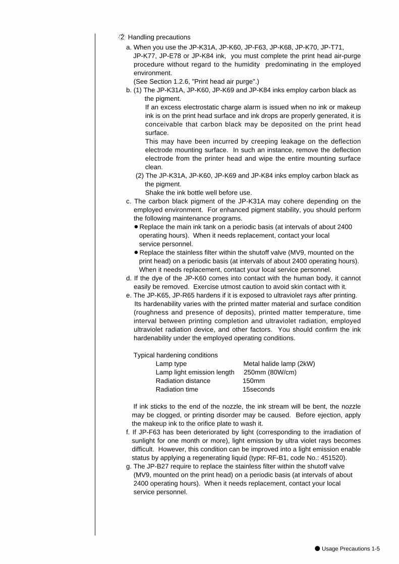
Handling precautions2
a. When you use the JP-K31A, JP-K60, JP-F63, JP-K68, JP-K70, JP-T71, JP-K77, JP-E78 or JP-K84 ink, you must complete the print head air-purgeprocedure without regard to the humidity predominating in the employedenvironment. (See Section 1.2.6, "Print head air purge".)
b. (1) The JP-K31A, JP-K60, JP-K69 and JP-K84 inks employ carbon black as the pigment. If an excess electrostatic charge alarm is issued when no ink or makeupink is on the print head surface and ink drops are properly generated, it isconceivable that carbon black may be deposited on the print headsurface. This may have been incurred by creeping leakage on the deflectionelectrode mounting surface. In such an instance, remove the deflectionelectrode from the printer head and wipe the entire mounting surfaceclean.
(2) The JP-K31A, JP-K60, JP-K69 and JP-K84 inks employ carbon black as the pigment.Shake the ink bottle well before use.
c. The carbon black pigment of the JP-K31A may cohere depending on theemployed environment. For enhanced pigment stability, you should performthe following maintenance programs.¡Replace the main ink tank on a periodic basis (at intervals of about 2400
operating hours). When it needs replacement, contact your local service personnel.
¡Replace the stainless filter within the shutoff valve (MV9, mounted on the print head) on a periodic basis (at intervals of about 2400 operating hours). When it needs replacement, contact your local service personnel.
d. If the dye of the JP-K60 comes into contact with the human body, it cannoteasily be removed. Exercise utmost caution to avoid skin contact with it.
e. The JP-K65, JP-R65 hardens if it is exposed to ultraviolet rays after printing. Its hardenability varies with the printed matter material and surface condition(roughness and presence of deposits), printed matter temperature, timeinterval between printing completion and ultraviolet radiation, employedultraviolet radiation device, and other factors. You should confirm the inkhardenability under the employed operating conditions.
Typical hardening conditions Lamp type Metal halide lamp (2kW)Lamp light emission length 250mm (80W/cm)Radiation distance 150mmRadiation time 15seconds
If ink sticks to the end of the nozzle, the ink stream will be bent, the nozzlemay be clogged, or printing disorder may be caused. Before ejection, applythe makeup ink to the orifice plate to wash it.
f. If JP-F63 has been deteriorated by light (corresponding to the irradiation ofsunlight for one month or more), light emission by ultra violet rays becomesdifficult. However, this condition can be improved into a light emission enablestatus by applying a regenerating liquid (type: RF-B1, code No.: 451520).
g. The JP-B27 require to replace the stainless filter within the shutoff valve (MV9, mounted on the print head) on a periodic basis (at intervals of about 2400 operating hours). When it needs replacement, contact your local service personnel.
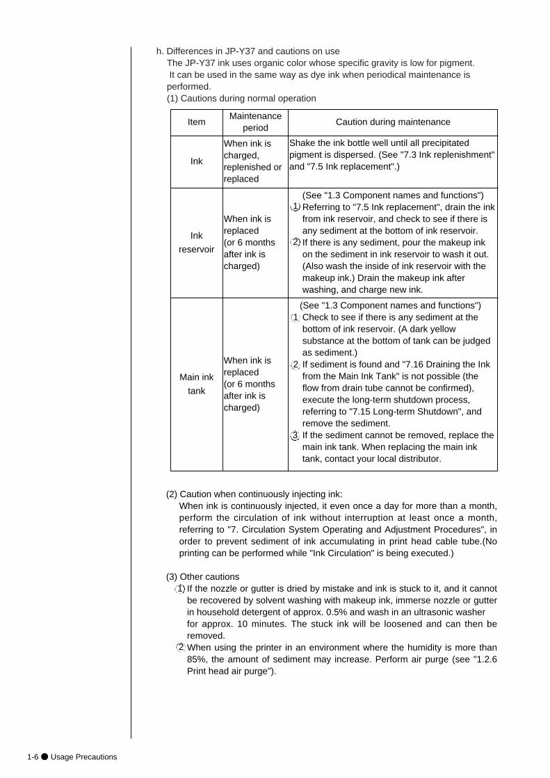
h. Differences in JP-Y37 and cautions on useThe JP-Y37 ink uses organic color whose specific gravity is low for pigment.It can be used in the same way as dye ink when periodical maintenance isperformed.(1) Cautions during normal operation
1-6● Usage Precautions
Item
Ink
Ink
reservoir
Main ink
tank
Maintenanceperiod
When ink ischarged,replenished orreplaced
When ink isreplaced (or 6 monthsafter ink ischarged)
When ink isreplaced (or 6 monthsafter ink ischarged)
Caution during maintenance
Shake the ink bottle well until all precipitatedpigment is dispersed. (See "7.3 Ink replenishment"and "7.5 Ink replacement".)
(See "1.3 Component names and functions")Referring to "7.5 Ink replacement", drain the inkfrom ink reservoir, and check to see if there isany sediment at the bottom of ink reservoir.If there is any sediment, pour the makeup inkon the sediment in ink reservoir to wash it out.(Also wash the inside of ink reservoir with themakeup ink.) Drain the makeup ink afterwashing, and charge new ink.
1
2
(See "1.3 Component names and functions")Check to see if there is any sediment at thebottom of ink reservoir. (A dark yellowsubstance at the bottom of tank can be judgedas sediment.)If sediment is found and "7.16 Draining the Inkfrom the Main Ink Tank" is not possible (theflow from drain tube cannot be confirmed),execute the long-term shutdown process,referring to "7.15 Long-term Shutdown", andremove the sediment.If the sediment cannot be removed, replace themain ink tank. When replacing the main inktank, contact your local distributor.
1
2
3
(2) Caution when continuously injecting ink: When ink is continuously injected, it even once a day for more than a month,perform the circulation of ink without interruption at least once a month,referring to "7. Circulation System Operating and Adjustment Procedures", inorder to prevent sediment of ink accumulating in print head cable tube.(Noprinting can be performed while "Ink Circulation" is being executed.)
(3) Other cautionsIf the nozzle or gutter is dried by mistake and ink is stuck to it, and it cannotbe recovered by solvent washing with makeup ink, immerse nozzle or gutterin household detergent of approx. 0.5% and wash in an ultrasonic washer for approx. 10 minutes. The stuck ink will be loosened and can then beremoved.When using the printer in an environment where the humidity is more than85%, the amount of sediment may increase. Perform air purge (see "1.2.6Print head air purge").
1
2
● Usage Precautions 1-7
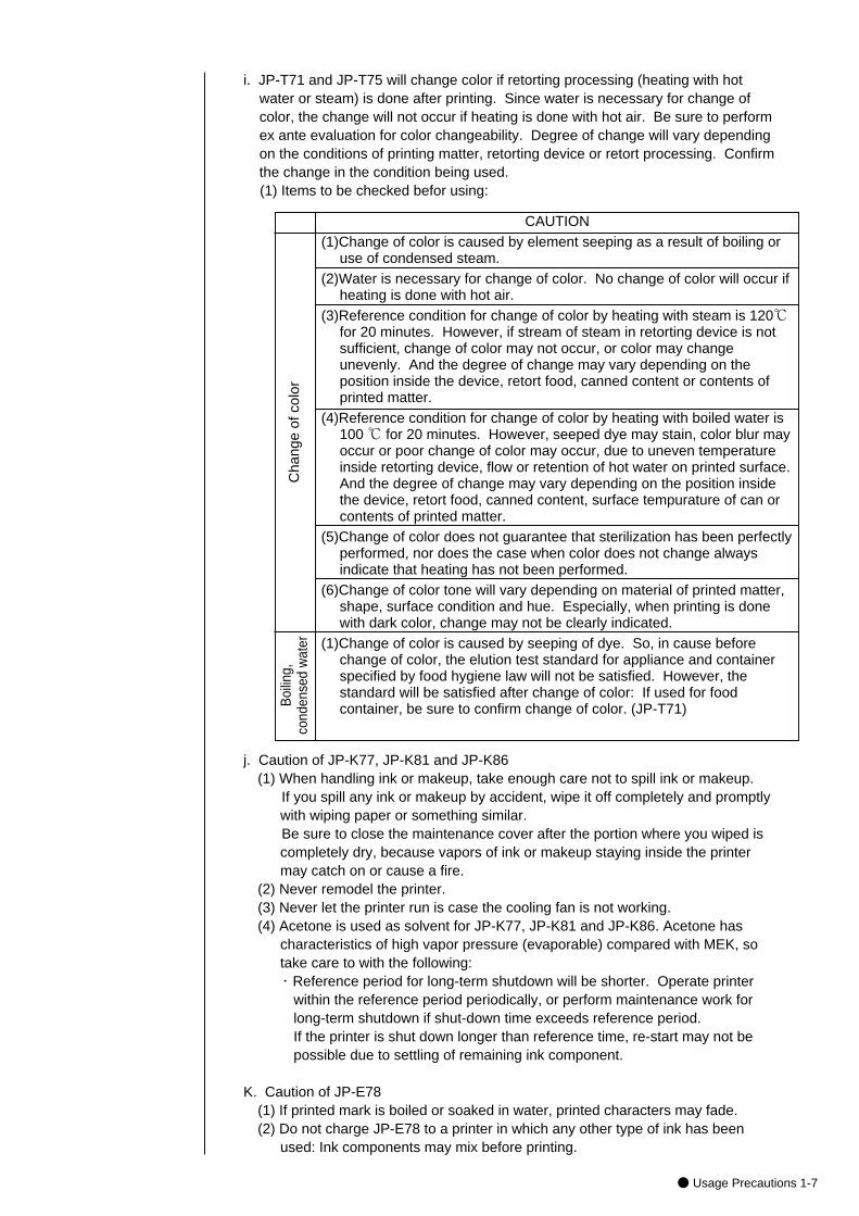
i. JP-T71 and JP-T75 will change color if retorting processing (heating with hot water or steam) is done after printing. Since water is necessary for change of color, the change will not occur if heating is done with hot air. Be sure to perform ex ante evaluation for color changeability. Degree of change will vary depending on the conditions of printing matter, retorting device or retort processing. Confirm the change in the condition being used.(1) Items to be checked befor using:
Cha
nge
of c
olor
CAUTION(1)Change of color is caused by element seeping as a result of boiling or
use of condensed steam.(2)Water is necessary for change of color. No change of color will occur if
heating is done with hot air.(3)Reference condition for change of color by heating with steam is 120℃
for 20 minutes. However, if stream of steam in retorting device is notsufficient, change of color may not occur, or color may changeunevenly. And the degree of change may vary depending on theposition inside the device, retort food, canned content or contents ofprinted matter.
(4)Reference condition for change of color by heating with boiled water is100 ℃ for 20 minutes. However, seeped dye may stain, color blur mayoccur or poor change of color may occur, due to uneven temperatureinside retorting device, flow or retention of hot water on printed surface.And the degree of change may vary depending on the position insidethe device, retort food, canned content, surface tempurature of can orcontents of printed matter.
(5)Change of color does not guarantee that sterilization has been perfectlyperformed, nor does the case when color does not change alwaysindicate that heating has not been performed.
(6)Change of color tone will vary depending on material of printed matter,shape, surface condition and hue. Especially, when printing is donewith dark color, change may not be clearly indicated.
(1)Change of color is caused by seeping of dye. So, in cause beforechange of color, the elution test standard for appliance and containerspecified by food hygiene law will not be satisfied. However, thestandard will be satisfied after change of color: If used for foodcontainer, be sure to confirm change of color. (JP-T71)B
oilin
g,
cond
ense
d w
ater
j. Caution of JP-K77, JP-K81 and JP-K86(1) When handling ink or makeup, take enough care not to spill ink or makeup.
If you spill any ink or makeup by accident, wipe it off completely and promptlywith wiping paper or something similar.Be sure to close the maintenance cover after the portion where you wiped iscompletely dry, because vapors of ink or makeup staying inside the printermay catch on or cause a fire.
(2) Never remodel the printer.(3) Never let the printer run is case the cooling fan is not working.(4) Acetone is used as solvent for JP-K77, JP-K81 and JP-K86. Acetone has
characteristics of high vapor pressure (evaporable) compared with MEK, sotake care to with the following:・ Reference period for long-term shutdown will be shorter. Operate printer
within the reference period periodically, or perform maintenance work for long-term shutdown if shut-down time exceeds reference period.If the printer is shut down longer than reference time, re-start may not be possible due to settling of remaining ink component.
K. Caution of JP-E78(1) If printed mark is boiled or soaked in water, printed characters may fade.(2) Do not charge JP-E78 to a printer in which any other type of ink has been
used: Ink components may mix before printing.
1-8● Usage Precautions
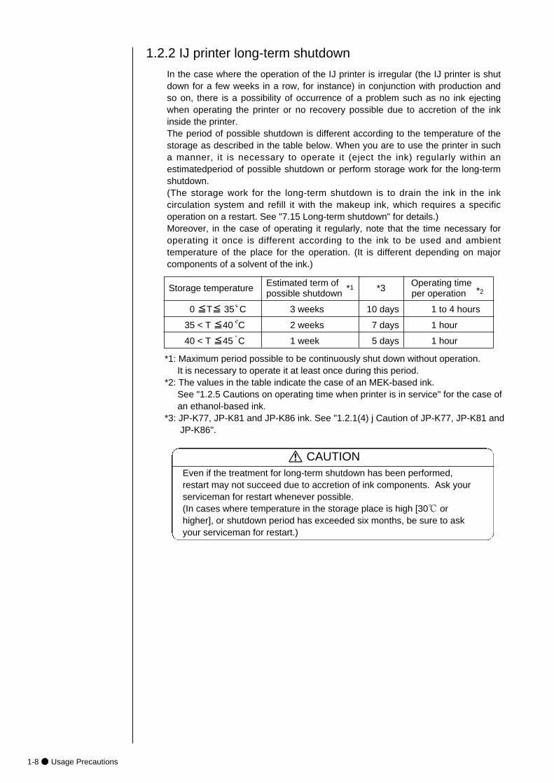
In the case where the operation of the IJ printer is irregular (the IJ printer is shutdown for a few weeks in a row, for instance) in conjunction with production andso on, there is a possibility of occurrence of a problem such as no ink ejectingwhen operating the printer or no recovery possible due to accretion of the inkinside the printer.The period of possible shutdown is different according to the temperature of thestorage as described in the table below. When you are to use the printer in sucha manner, it is necessary to operate it (eject the ink) regularly within anestimatedperiod of possible shutdown or perform storage work for the long-termshutdown.(The storage work for the long-term shutdown is to drain the ink in the inkcirculation system and refill it with the makeup ink, which requires a specificoperation on a restart. See "7.15 Long-term shutdown" for details.)Moreover, in the case of operating it regularly, note that the time necessary foroperating it once is different according to the ink to be used and ambienttemperature of the place for the operation. (It is different depending on majorcomponents of a solvent of the ink.)
1.2.2 IJ printer long-term shutdown
Storage temperature Estimated term of *1 *3 Operating timepossible shutdown per operation *2
0 ≦T≦ 35 C 3 weeks 10 days 1 to 4 hours
35 < T ≦40 C 2 weeks 7 days 1 hour
40 < T ≦45 C 1 week 5 days 1 hour
*1: Maximum period possible to be continuously shut down without operation.It is necessary to operate it at least once during this period.
*2: The values in the table indicate the case of an MEK-based ink.See "1.2.5 Cautions on operating time when printer is in service" for the case of an ethanol-based ink.
*3: JP-K77, JP-K81 and JP-K86 ink. See "1.2.1(4) j Caution of JP-K77, JP-K81 and JP-K86".
Even if the treatment for long-term shutdown has been performed,restart may not succeed due to accretion of ink components. Ask yourserviceman for restart whenever possible.(In cases where temperature in the storage place is high [30℃ orhigher], or shutdown period has exceeded six months, be sure to askyour serviceman for restart.)
CAUTION
● Usage Precautions 1-9
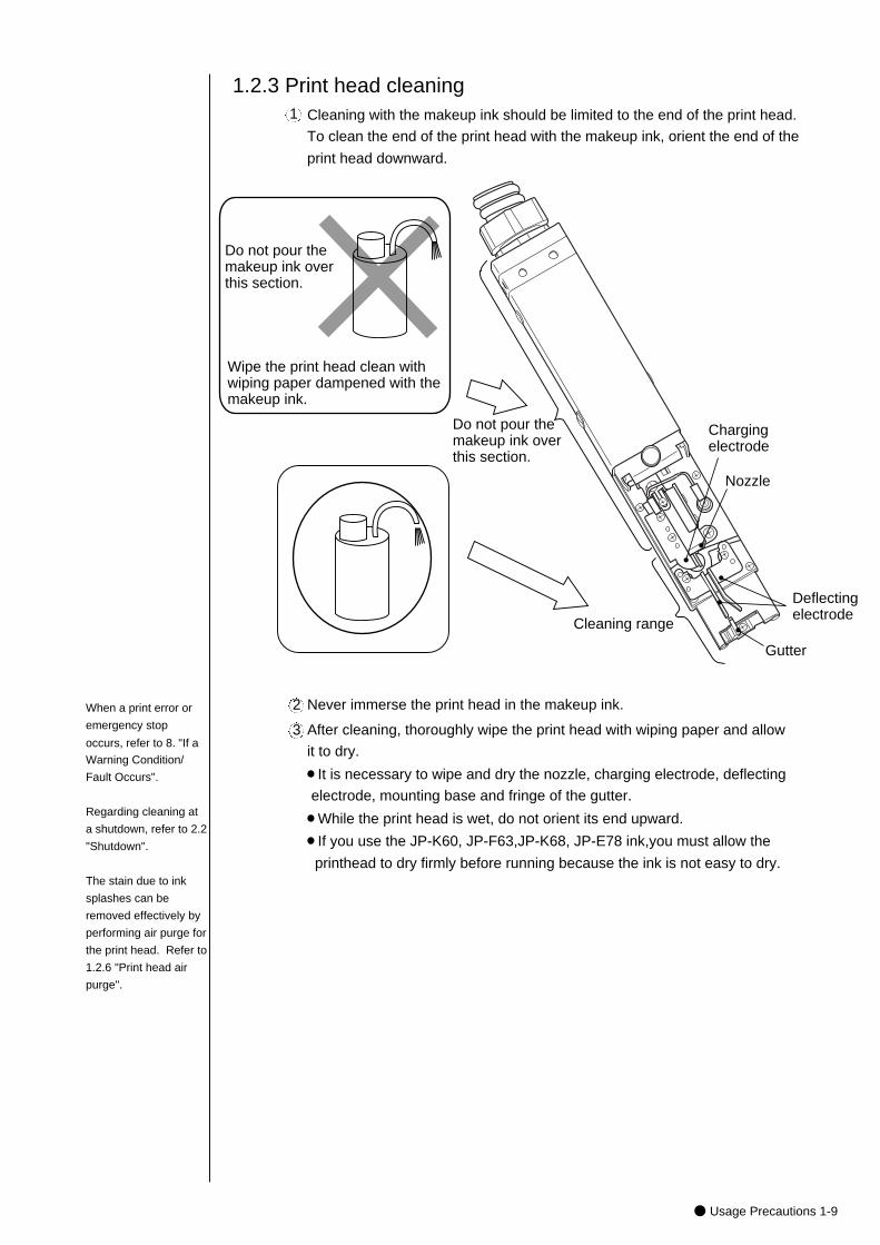
After cleaning, thoroughly wipe the print head with wiping paper and allow
it to dry.
¡It is necessary to wipe and dry the nozzle, charging electrode, deflecting
electrode, mounting base and fringe of the gutter.
¡While the print head is wet, do not orient its end upward.
¡If you use the JP-K60, JP-F63,JP-K68, JP-E78 ink,you must allow the
printhead to dry firmly before running because the ink is not easy to dry.
Never immerse the print head in the makeup ink.2
3
Cleaning with the makeup ink should be limited to the end of the print head.
To clean the end of the print head with the makeup ink, orient the end of the
print head downward.
1
1.2.3 Print head cleaning
Nozzle
Do not pour the makeup ink over this section.
Cleaning range
Deflecting electrode
Gutter
Do not pour the makeup ink over this section.
Charging electrode
Wipe the print head clean with wiping paper dampened with the makeup ink.
When a print error or
emergency stop
occurs, refer to 8. "If a
Warning Condition/
Fault Occurs".
Regarding cleaning at
a shutdown, refer to 2.2
"Shutdown".
The stain due to ink
splashes can be
removed effectively by
performing air purge for
the print head. Refer to
1.2.6 "Print head air
purge".
1-10● Usage Precautions
When printing is frequently performed or an space between the print material and theprint head is small, ink splashes may stain the end of the print head and the printhead cover. If this condition is left as it is, the stained status will be made worse,resulting in a print error or emergency stop. If a print error or emergency stopfrequently occurs because of stain due to ink splashes, stop the operation that is inprogress and clean the end of the print head and the print head cover. Do this inaddition to the cleaning to be performed at the end of each daily work.
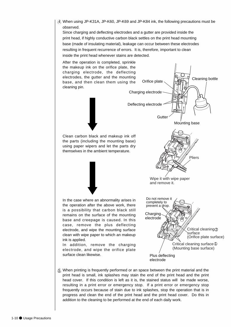
Since charging and deflecting electrodes and a gutter are provided inside the
print head, if highly conductive carbon black settles on the print head mounting
base (made of insulating material), leakage can occur between these electrodes
resulting in frequent recurrence of errors. It is, therefore, important to clean
inside the print head whenever stains are detected.
After the operation is completed, sprinklethe makeup ink on the orifice plate, thecharging electrode, the deflectingelectrodes, the gutter and the mountingbase, and then clean them using thecleaning pin.
Clean carbon black and makeup ink offthe parts (including the mounting base)using paper wipers and let the parts drythemselves in the ambient temperature.
In the case where an abnormality arises inthe operation after the above work, thereis a possibility that carbon black stillremains on the surface of the mountingbase and creepage is caused. In thiscase, remove the plus deflectingelectrode, and wipe the mounting surfaceclean with wipe paper to which an makeupink is applied.In addit ion, remove the chargingelectrode, and wipe the orif ice platesurface clean likewise.
5
Plus deflecting electrode
Deflecting electrode
Gutter
Charging electrode
Pliers
Wipe it with wipe paper and remove it.
Critical cleaning surface (Mounting base surface)
1
2
Do not remove it completely to prevent a drop.
Mounting base
Cleaning bottle
Charging electrode
Critical cleaning surface (Orifice plate surface)
Orifice plate
When using JP-K31A, JP-K60, JP-K69 and JP-K84 ink, the following precautions must be
observed.
4
● Usage Precautions 1-11
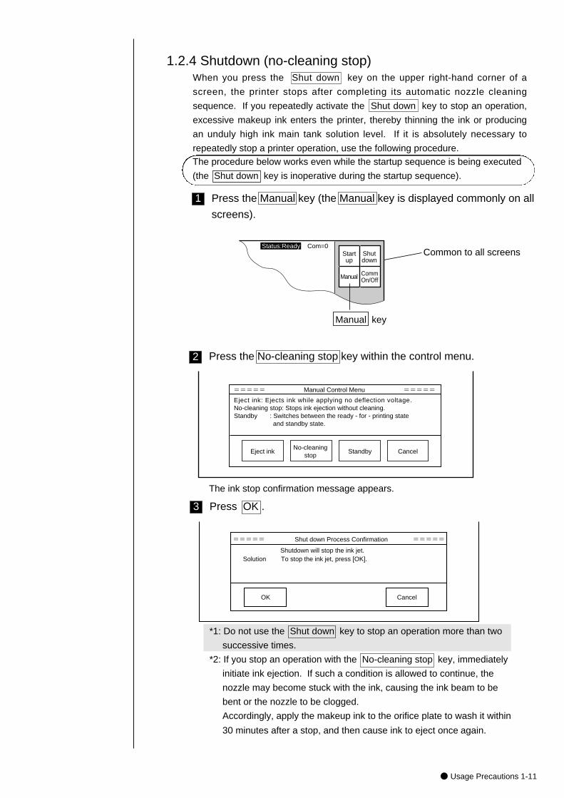
Press the No-cleaning stop key within the control menu.2
Eject ink: Ejects ink while applying no deflection voltage.No-cleaning stop: Stops ink ejection without cleaning.Standby : Switches between the ready - for - printing state and standby state.
Eject inkNo-cleaning
stopStandby Cancel
===== Manual Control Menu =====
*1: Do not use the Shut down key to stop an operation more than two
successive times.
*2: If you stop an operation with the No-cleaning stop key, immediately
initiate ink ejection. If such a condition is allowed to continue, the
nozzle may become stuck with the ink, causing the ink beam to be
bent or the nozzle to be clogged.
Accordingly, apply the makeup ink to the orifice plate to wash it within
30 minutes after a stop, and then cause ink to eject once again.
Press OK .3
The ink stop confirmation message appears.
===== Shut down Process Confirmation =====
Shutdown will stop the ink jet.Solution To stop the ink jet, press [OK].
OK Cancel
When you press the Shut down key on the upper right-hand corner of a
screen, the printer stops after completing its automatic nozzle cleaning
sequence. If you repeatedly activate the Shut down key to stop an operation,
excessive makeup ink enters the printer, thereby thinning the ink or producing
an unduly high ink main tank solution level. If it is absolutely necessary to
repeatedly stop a printer operation, use the following procedure.
1.2.4 Shutdown (no-cleaning stop)
Press the Manual key (the Manual key is displayed commonly on all
screens).
1
Startup
Shutdown
Manual CommOn/Off
Manual key
Common to all screens Status:Ready Com=0
The procedure below works even while the startup sequence is being executed
(the Shut down key is inoperative during the startup sequence).
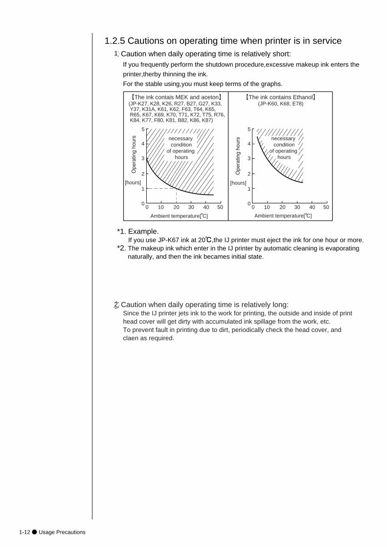
Caution when daily operating time is relatively long:Since the IJ printer jets ink to the work for printing, the outside and inside of printhead cover will get dirty with accumulated ink spillage from the work, etc. To prevent fault in printing due to dirt, periodically check the head cover, andclaen as required.
1-12● Usage Precautions
1.2.5 Cautions on operating time when printer is in serviceCaution when daily operating time is relatively short:If you frequently perform the shutdown procedure,excessive makeup ink enters the
printer,therby thinning the ink.
For the stable using,you must keep terms of the graphs.
0 10 20 30 40 50
1
2
3
4
5
Ambient temperature[ C]
[hours]
【The ink contais MEK and aceton】(JP-K27, K28, K26, R27, B27, G27, K33, Y37, K31A, K61, K62, F63, T64, K65, R65, K67, K69, K70, T71, K72, T75, R76, K84, K77, F80, K81, B82, K86, K87)
0
necessary condition
of operating hours
0 10 20 30 40 50
1
2
3
4
5
【The ink contains Ethanol】(JP-K60, K68, E78)
0
[hours]
necessary condition
of operating hours
Ambient temperature[ C]
*1. Example.If you use JP-K67 ink at 20℃,the IJ printer must eject the ink for one hour or more.
*2. The makeup ink which enter in the IJ printer by automatic cleaning is evaporating naturally, and then the ink becames initial state.
1
2
● Usage Precautions 1-13
(1) Situations requiring an air purge
When the printer is used in a highly humid place such as a beer or other
beverage can line (If you use the printer in an environment in which the
relative humidity is 85% or higher, complete the print head air-purge
procedure).
When a water drainage blow sequence is performed before printing.
When the printer is used in a place where a considerable amount of paper
powder or other dust exists.
When the printing distance is short so that the end of the print head is
splashed with ink.
When you use the JP-K31A, JP-K60, JP-F63,JP-K68, JP-K70, JP-T71,
JP-K77, JP-E78, JP-K84 ink.
5
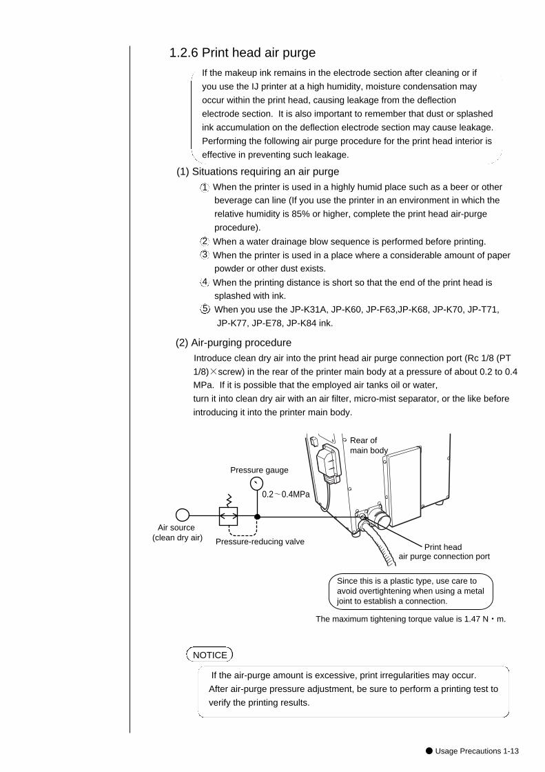
(2) Air-purging procedure
Introduce clean dry air into the print head air purge connection port (Rc 1/8 (PT
1/8)×screw) in the rear of the printer main body at a pressure of about 0.2 to 0.4
MPa. If it is possible that the employed air tanks oil or water,
turn it into clean dry air with an air filter, micro-mist separator, or the like before
introducing it into the printer main body.
NOTICE
Pressure gauge
Pressure-reducing valvePrint head
air purge connection port
Rear of main body
Air source (clean dry air)
Since this is a plastic type, use care to avoid overtightening when using a metal joint to establish a connection.
The maximum tightening torque value is 1.47 N・m.
0.2~0.4MPa
If the air-purge amount is excessive, print irregularities may occur.
After air-purge pressure adjustment, be sure to perform a printing test to
verify the printing results.
1.2.6 Print head air purge
1
2
3
4
If the makeup ink remains in the electrode section after cleaning or if
you use the IJ printer at a high humidity, moisture condensation may
occur within the print head, causing leakage from the deflection
electrode section. It is also important to remember that dust or splashed
ink accumulation on the deflection electrode section may cause leakage.
Performing the following air purge procedure for the print head interior is
effective in preventing such leakage.
1-14● Usage Precautions
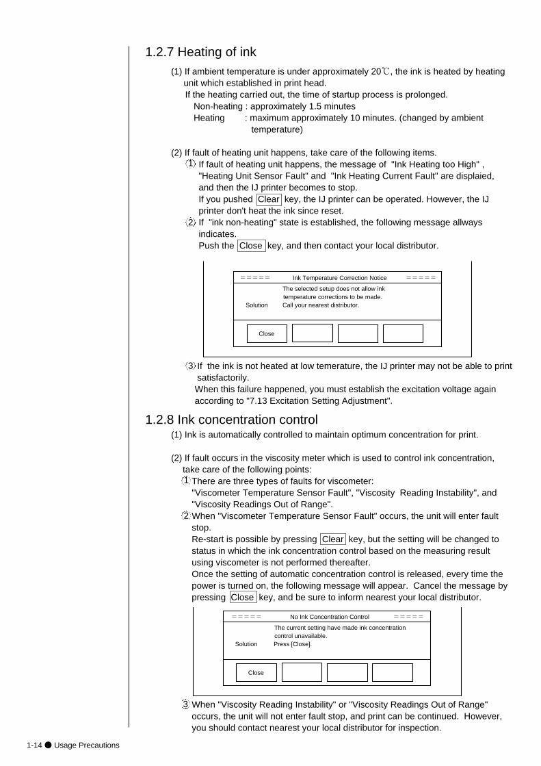
If the ink is not heated at low temerature, the IJ printer may not be able to print satisfactorily.When this failure happened, you must establish the excitation voltage again according to "7.13 Excitation Setting Adjustment".
(1) If ambient temperature is under approximately 20℃, the ink is heated by heating unit which established in print head.If the heating carried out, the time of startup process is prolonged.
Non-heating : approximately 1.5 minutesHeating : maximum approximately 10 minutes. (changed by ambient
temperature)
(2) If fault of heating unit happens, take care of the following items.If fault of heating unit happens, the message of "Ink Heating too High" , "Heating Unit Sensor Fault" and "Ink Heating Current Fault" are displaied, and then the IJ printer becomes to stop.If you pushed Clear key, the IJ printer can be operated. However, the IJ printer don't heat the ink since reset.If "ink non-heating" state is established, the following message allways indicates.Push the Close key, and then contact your local distributor.
1.2.7 Heating of ink
1
2
3
===== Ink Temperature Correction Notice =====
The selected setup does not allow ink temperature corrections to be made.Solution Call your nearest distributor.
Close
1.2.8 Ink concentration control
===== No Ink Concentration Control =====
The current setting have made ink concentration control unavailable.Solution Press [Close].
Close
(1) Ink is automatically controlled to maintain optimum concentration for print.
(2) If fault occurs in the viscosity meter which is used to control ink concentration,take care of the following points:
There are three types of faults for viscometer: "Viscometer Temperature Sensor Fault", "Viscosity Reading Instability", and"Viscosity Readings Out of Range".When "Viscometer Temperature Sensor Fault" occurs, the unit will enter faultstop.Re-start is possible by pressing Clear key, but the setting will be changed tostatus in which the ink concentration control based on the measuring resultusing viscometer is not performed thereafter. Once the setting of automatic concentration control is released, every time thepower is turned on, the following message will appear. Cancel the message by pressing Close key, and be sure to inform nearest your local distributor.
1
2
When "Viscosity Reading Instability" or "Viscosity Readings Out of Range"occurs, the unit will not enter fault stop, and print can be continued. However,you should contact nearest your local distributor for inspection.
3
● Usage Precautions 1-15
1.2.9 Gutter cleaning
1.2.10 Protection Sheet for touch panel
The IJ printer collects ink not used for printing, from the gutter. At the same time, it sucks in atmospheric gas, dust and other matter from the air. If these substances are mixed with ink in the gutter, undissolved components by the ink or makeup ink maystick to the gutter. If the system is run for 24 consecutive hours without automaticcleaning, these components get accumulated gradually in the gutter. This, togetherwith the ink beam coming into contact with it, may cause such errors as "an errorstemming from a dirty head."If any such component sticks to the gutter, immerse it in a solution of about 0.5%
household dish detergent and clean it for about 10 minutes with an ultrasonic cleaner. The dirt can then be removed.
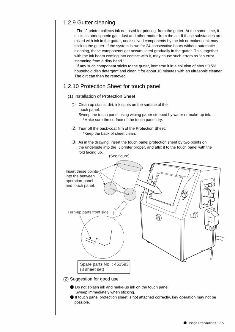
(1) Installation of Protection Sheet
Clean up stains, dirt, ink spots on the surface of the touch panel.Sweep the touch panel using wiping paper steeped by water or make-up ink.
*Make sure the surface of the touch panel dry.
Tear off the back-coat film of the Protection Sheet.*Keep the back of sheet clean.
As in the drawing, insert the touch panel protection sheet by two points onthe underside into the IJ printer proper, and affix it to the touch panel with thefold facing up.
(See figure)
(2) Suggestion for good use
● Do not splash ink and make-up ink on the touch panel.Sweep immediately when sticking.
● If touch panel protection sheet is not attached correctly, key operation may not bepossible.
Insert these points into the between operation-paneland touch panel.
Turn-up parts front side
Spare parts No. : 451593(3 sheet set)
1
2
3
1-16● Component Names and Functions
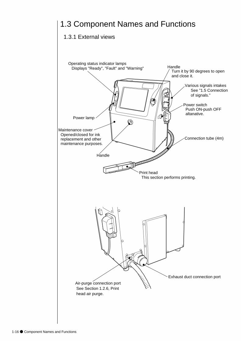
1.3 Component Names and Functions
1.3.1 External views
Power switch Push ON-push OFF altanative.
Maintenance cover Opened/closed for ink replacement and other maintenance purposes.
Handle
Print head This section performs printing.
Operating status indicator lamps Displays "Ready", "Fault" and "Warning"
Connection tube (4m)
Power lamp
Various signals intakesSee "1.5 Connection of signals."
Handle
Turn it by 90 degrees to open and close it.
Air-purge connection port See Section 1.2.6, Print head air purge.
Exhaust duct connection port
● Component Names and Functions 1-17
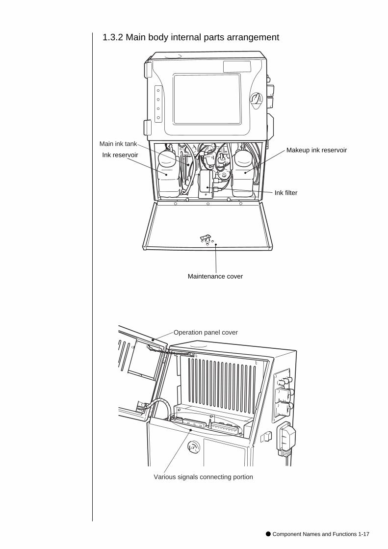
1.3.2 Main body internal parts arrangement
Ink reservoir
Ink filter
Makeup ink reservoir
Maintenance cover
Various signals connecting portion
Operation panel cover
Main ink tank
1-18● Component Names and Functions
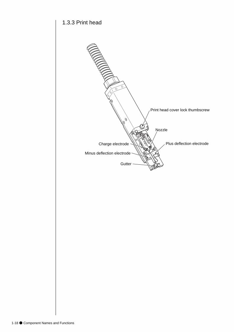
1.3.3 Print head
Print head cover lock thumbscrew
Nozzle
Minus deflection electrode
Plus deflection electrode
Gutter
Charge electrode
● Installing Precautions 1-19
(4) The IJ printer main body must be installed with alevelness error of not over ±1°.
(5) The IJ printer main body must be electrically insulated from the other equipment (conveyors, packing machines,etc.), photoelectric switches, and the rotary encoder.
(6) The standard distance between the printing head and the object to be printed on is as indicated in the right-hand table. The smaller the clearance between the print head and print target, the smaller the character height.
(7) The IJ printer proper requires maintenance as the occasionmay demand including replenishment of ink and makeup ink and replacement of filter.
¡Ensure that there is no flame- or arc-generating device within 5m of the printer.
The ink and makeup ink are both flammable and may cause ignitionor fire. Flames can be generated by matches, lighters, cigarettes,heaters, stoves, gas burners, welders, grinders, and static electricity.Arcs may be generated from open-type relays, switches, and brushmotors. Before handling the ink and makeup ink, remove electricity from human body, the peripheral equipment, and so on. In theinterests of safety, furnish a dry-chemical fire extinguisher near the printer.
¡Since the ink and makeup ink contain organic solvents, installthe printer at a location where adequate ventilation (airexhaust) is provided.
1 Never install the printer in an enclosed space.2 Connect the printer to exhaust equipment in order to prevent the
organic solvent vapor from being retained.
WARNING
CAUTION
1.4 Installing Precautions
¡The employed ink and makeup ink contain organic solvents.
Furnish an adequate space for the ink/makeup ink handling area and
printer installation site. A space of at least 200 m3 must be provided
per print head. Ensure that adequate ventilation is provided.
Follow all regulation in your country.
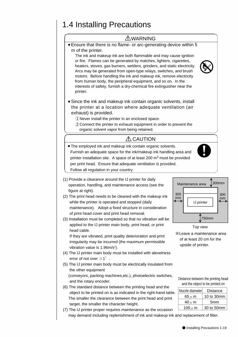
(1) Provide a clearance around the IJ printer for dailyoperation, handling, and maintenance access (see the figure at right).
(2) The print head needs to be cleaned with the makeup inkwhile the printer is operated and stopped (dailymaintenance). Adopt a fixed structure in considerationof print head cover and print head removal.
(3) Installation must be completed so that no vibration will beapplied to the IJ printer main body, print head, or print head cable. If they are vibrated, print quality deterioration and print irregularity may be incurred (the maximum permissiblevibration value is 1.96m/s2).
IJ printer
Maintenance area
300mm
Top view
300mm
300mm
750mm
Distance between the printing headand the object to be printed on
Nozzle diameter65μm40μm100μm
Distance10 to 30mm
5mm30 to 50mm
※Leave a maintenance areaof at least 20 cm for theupside of printer.
1-20● Installing Precautions
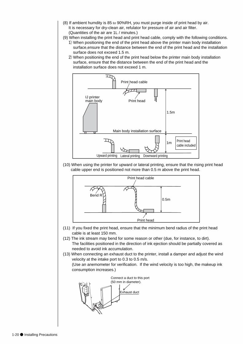
(8) If ambient humdity is 85 to 90%RH, you must purge inside of print head by air. It is necessary for dry-clean air, refulator for pressure of air and air filter.(Quantities of the air are 1L / minutes.)
(9) When installing the print head and print head cable, comply with the following conditions.1 When positioning the end of the print head above the printer main body installation
surface,ensure that the distance between the end of the print head and the installationsurface does not exceed 1.5 m.
2 When positioning the end of the print head below the printer main body installation surface, ensure that the distance between the end of the print head and the installation surface does not exceed 1 m.
Upward printing Lateral printing Downward printing
Print head cable included
1m
1.5m
Print head
Print head cable
Main body installation surface
IJ printer main body
(10) When using the printer for upward or lateral printing, ensure that the rising print head cable upper end is positioned not more than 0.5 m above the print head.
Print head
Print head cable
Bend R0.5m
(11) If you fixed the print head, ensure that the minimum bend radius of the print head cable is at least 150 mm.
(12) The ink stream may bend for some reason or other (due, for instance, to dirt). The facilities positioned in the direction of ink ejection should be partially covered asneeded to avoid ink accumulation.
(13) When connecting an exhaust duct to the printer, install a damper and adjust the windvelocity at the intake port to 0.3 to 0.5 m/s. (Use an anemometer for verification. If the wind velocity is too high, the makeup inkconsumption increases.)
Exhaust duct
Connect a duct to this port (50 mm in diameter).
● Installing Precautions 1-21
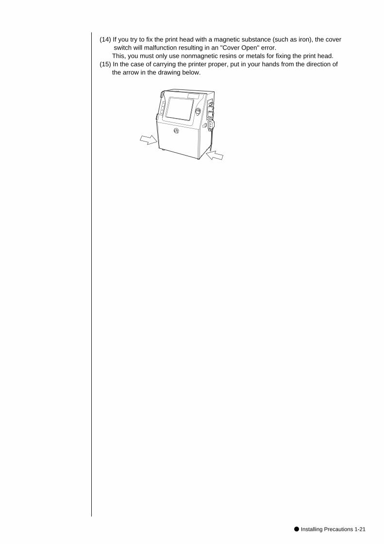
(14) If you try to fix the print head with a magnetic substance (such as iron), the coverswitch will malfunction resulting in an "Cover Open" error.This, you must only use nonmagnetic resins or metals for fixing the print head.
(15) In the case of carrying the printer proper, put in your hands from the direction of the arrow in the drawing below.
1-22● Connection of signals
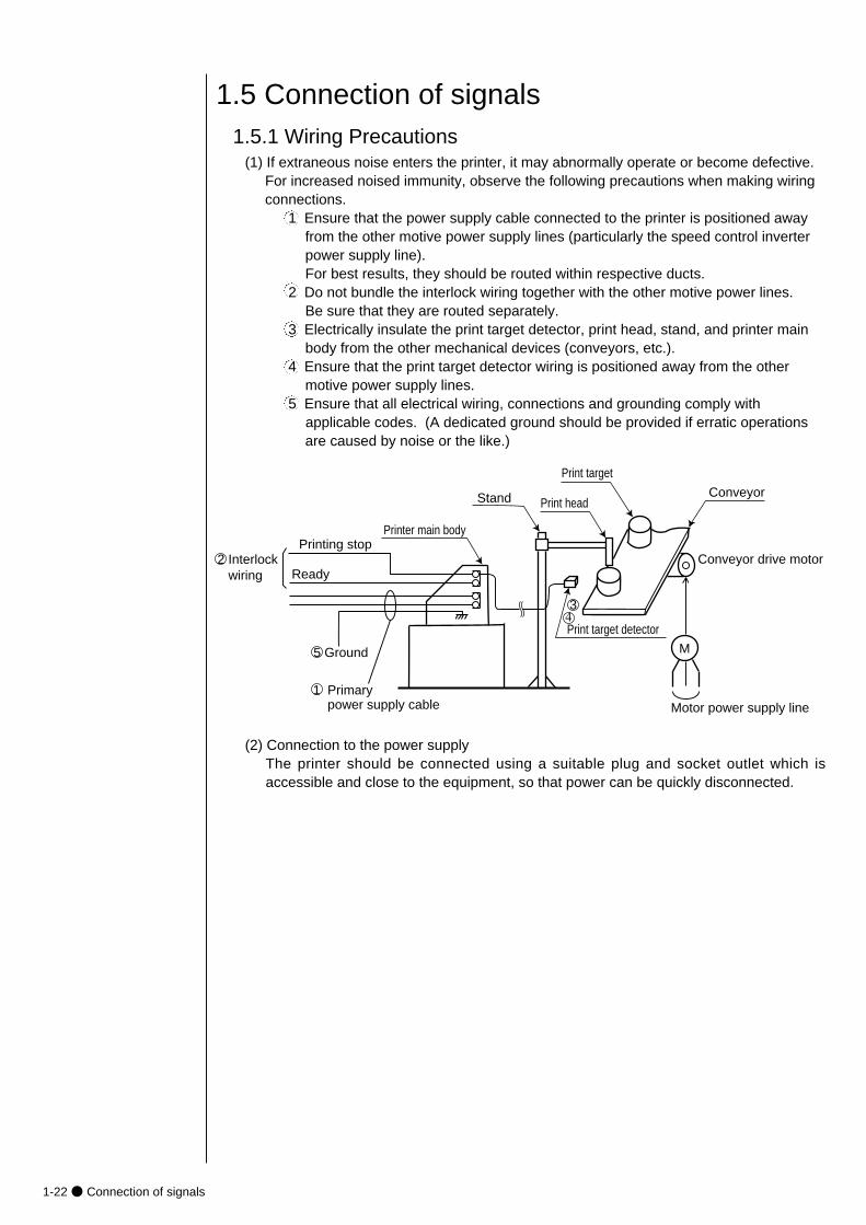
1.5.1 Wiring Precautions(1) If extraneous noise enters the printer, it may abnormally operate or become defective.
For increased noised immunity, observe the following precautions when making wiring connections.
1 Ensure that the power supply cable connected to the printer is positioned awayfrom the other motive power supply lines (particularly the speed control inverterpower supply line). For best results, they should be routed within respective ducts.
2 Do not bundle the interlock wiring together with the other motive power lines. Be sure that they are routed separately.
3 Electrically insulate the print target detector, print head, stand, and printer mainbody from the other mechanical devices (conveyors, etc.).
4 Ensure that the print target detector wiring is positioned away from the other motive power supply lines.
5 Ensure that all electrical wiring, connections and grounding comply with applicable codes. (A dedicated ground should be provided if erratic operationsare caused by noise or the like.)
Motor power supply line
M
Conveyor drive motor
Conveyor
Print target detector
Print head
Print target
Stand
Printing stop
Ready
Printer main body
2 Interlock wiring
1 Primary power supply cable
5 Ground
34
(2) Connection to the power supplyThe printer should be connected using a suitable plug and socket outlet which isaccessible and close to the equipment, so that power can be quickly disconnected.
1.5 Connection of signals
● Connection of signals 1-23
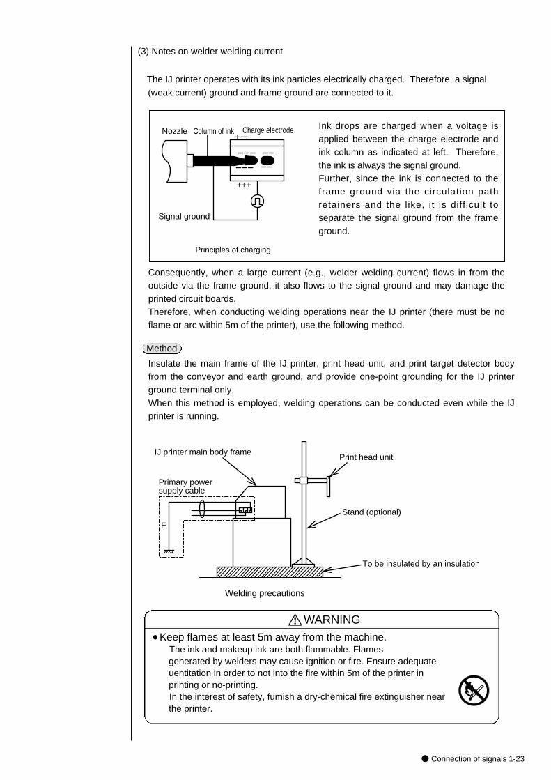
(3) Notes on welder welding current
The IJ printer operates with its ink particles electrically charged. Therefore, a signal
(weak current) ground and frame ground are connected to it.
+++
+++
Signal ground
Nozzle Column of ink Charge electrode
Consequently, when a large current (e.g., welder welding current) flows in from theoutside via the frame ground, it also flows to the signal ground and may damage theprinted circuit boards. Therefore, when conducting welding operations near the IJ printer (there must be noflame or arc within 5m of the printer), use the following method.
Insulate the main frame of the IJ printer, print head unit, and print target detector bodyfrom the conveyor and earth ground, and provide one-point grounding for the IJ printerground terminal only. When this method is employed, welding operations can be conducted even while the IJprinter is running.
Method
Primary power supply cable
Print head unit
Stand (optional)
To be insulated by an insulation
IJ printer main body frame
Welding precautions
E
Ink drops are charged when a voltage isapplied between the charge electrode andink column as indicated at left. Therefore,the ink is always the signal ground. Further, since the ink is connected to theframe ground via the circulation pathretainers and the l ike, it is diff icult toseparate the signal ground from the frameground.
Principles of charging
WARNING¡Keep flames at least 5m away from the machine.
The ink and makeup ink are both flammable. Flamesgeherated by welders may cause ignition or fire. Ensure adequateuentitation in order to not into the fire within 5m of the printer inprinting or no-printing.In the interest of safety, fumish a dry-chemical fire extinguisher nearthe printer.
1-24● Connection of signals
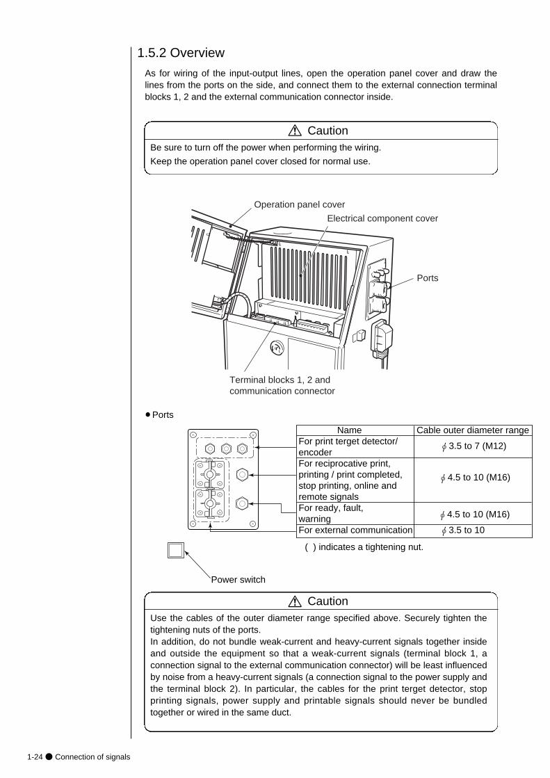
1.5.2 Overview
As for wiring of the input-output lines, open the operation panel cover and draw thelines from the ports on the side, and connect them to the external connection terminalblocks 1, 2 and the external communication connector inside.
CautionBe sure to turn off the power when performing the wiring.
Keep the operation panel cover closed for normal use.
Terminal blocks 1, 2 and communication connector
Operation panel cover
Electrical component cover
Ports
Name Cable outer diameter rangeFor print terget detector/ φ3.5 to 7 (M12)encoder For reciprocative print,printing / print completed, φ4.5 to 10 (M16) stop printing, online and remote signalsFor ready, fault,
φ4.5 to 10 (M16)
warning For external communication φ3.5 to 10
( ) indicates a tightening nut.
Power switch
CautionUse the cables of the outer diameter range specified above. Securely tighten thetightening nuts of the ports. In addition, do not bundle weak-current and heavy-current signals together insideand outside the equipment so that a weak-current signals (terminal block 1, aconnection signal to the external communication connector) will be least influencedby noise from a heavy-current signals (a connection signal to the power supply andthe terminal block 2). In particular, the cables for the print terget detector, stopprinting signals, power supply and printable signals should never be bundledtogether or wired in the same duct.
¡Ports
● Connection of signals 1-25
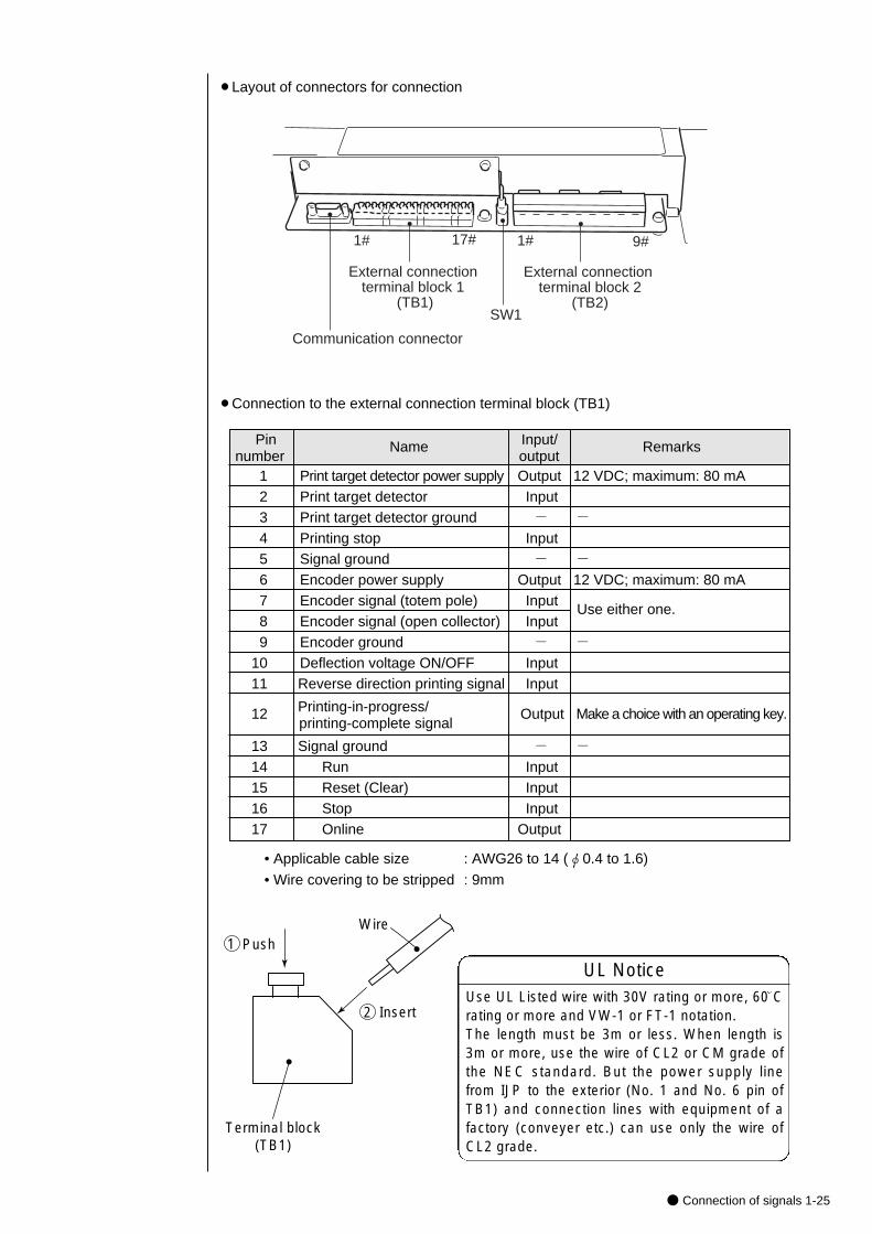
¡Layout of connectors for connection
Communication connector
External connection terminal block 1
(TB1)
1# 17# 1# 9#
External connection terminal block 2
(TB2)SW1
¡Connection to the external connection terminal block (TB1)
Pin Name Input/ Remarksnumber output
1 Print target detector power supply Output 12 VDC; maximum: 80 mA2 Print target detector Input3 Print target detector ground - -4 Printing stop Input5 Signal ground - -6 Encoder power supply Output 12 VDC; maximum: 80 mA7 Encoder signal (totem pole) Input8 Encoder signal (open collector) Input9 Encoder ground - -
10 Deflection voltage ON/OFF Input 11 Reverse direction printing signal Input
12 Printing-in-progress/ Output Make a choice with an operating key. printing-complete signal
13 Signal ground - -14 Run Input 15 Reset (Clear) Input 16 Stop Input 17 Online Output
Use either one.
• Applicable cable size : AWG26 to 14 (φ0.4 to 1.6)
• Wire covering to be stripped : 9mm
Terminal block(TB1)
WirePush1
2 Insert
UL NoticeUse UL Listed wire with 30V rating or more, 60 Crating or more and VW-1 or FT-1 notation.The length must be 3m or less. When length is3m or more, use the wire of CL2 or CM grade ofthe NEC standard. But the power supply linefrom IJP to the exterior (No. 1 and No. 6 pin ofTB1) and connection lines with equipment of afactory (conveyer etc.) can use only the wire ofCL2 grade.
1-26● Connection of signals
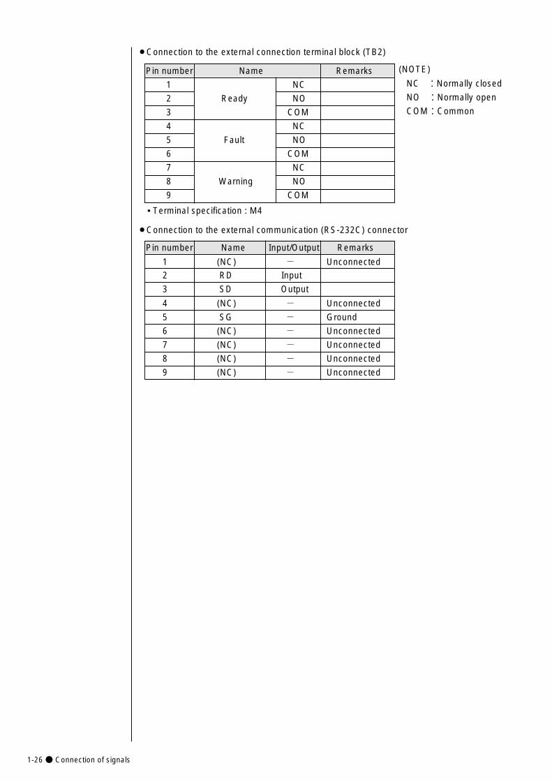
Pin number Name Remarks
1 NC
2 Ready NO
3 COM
4 NC
5 Fault NO
6 COM
7 NC
8 Warning NO
9 COM
¡Connection to the external connection terminal block (TB2)
(NOTE)
NC :Normally closed
NO :Normally open
COM:Common
• Terminal specification : M4
Pin number Name Input/Output Remarks
1 (NC) - Unconnected
2 RD Input
3 SD Output
4 (NC) - Unconnected
5 SG - Ground
6 (NC) - Unconnected
7 (NC) - Unconnected
8 (NC) - Unconnected
9 (NC) - Unconnected
¡Connection to the external communication (RS-232C) connector
● Connection of signals 1-27
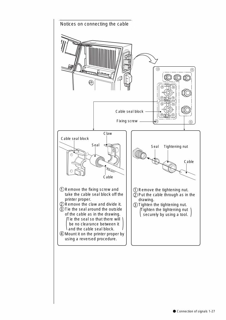
Cable seal block
Fixing screw
Seal Tightening nut
Cable
Cable seal block
Seal
Cable
Claw
Remove the fixing screw and take the cable seal block off the printer proper.Remove the claw and divide it.Tie the seal around the outside of the cable as in the drawing. Tie the seal so that there will be no clearance between it and the cable seal block.Mount it on the printer proper byusing a reversed procedure.
1
23
4
( )
Remove the tightening nut.Put the cable through as in the drawing. Tighten the tightening nut. Tighten the tightening nut securely by using a tool.
12
3
)(
Notices on connecting the cable
1-28● Connection of signals
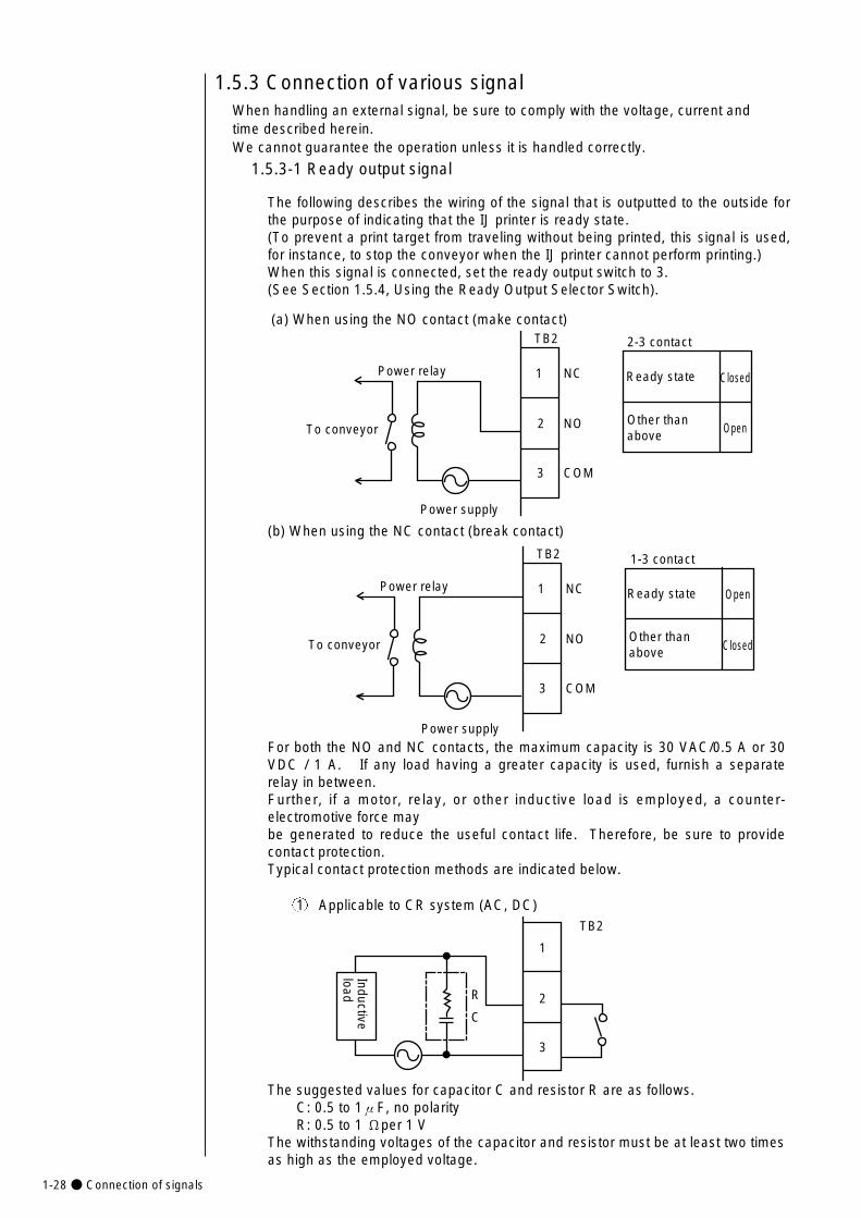
1.5.3-1 Ready output signal
The following describes the wiring of the signal that is outputted to the outside forthe purpose of indicating that the IJ printer is ready state. (To prevent a print target from traveling without being printed, this signal is used,for instance, to stop the conveyor when the IJ printer cannot perform printing.)When this signal is connected, set the ready output switch to 3. (See Section 1.5.4, Using the Ready Output Selector Switch).
(a) When using the NO contact (make contact)
1.5.3 Connection of various signal
(b) When using the NC contact (break contact)
For both the NO and NC contacts, the maximum capacity is 30 VAC/0.5 A or 30VDC / 1 A. If any load having a greater capacity is used, furnish a separaterelay in between.Further, if a motor, relay, or other inductive load is employed, a counter-electromotive force maybe generated to reduce the useful contact life. Therefore, be sure to providecontact protection.Typical contact protection methods are indicated below.
1 Applicable to CR system (AC, DC)
The suggested values for capacitor C and resistor R are as follows.C: 0.5 to 1μF, no polarityR: 0.5 to 1 Ωper 1 V
The withstanding voltages of the capacitor and resistor must be at least two timesas high as the employed voltage.
Power relay
To conveyor
Power supply
TB2
1
2
3
NC
NO
COM
Ready state Closed
Other than above
Open
2-3 contact
Power relay
To conveyor
Power supply
TB2
1
2
3
NC
NO
COM
Open
Closed
1-3 contact
Ready state
Other than above
Inductive load R
C
TB2
1
2
3
When handling an external signal, be sure to comply with the voltage, current and time described herein.We cannot guarantee the operation unless it is handled correctly.

● Connection of signals 1-29
2 Diode system (applicable to DC, inapplicable to AC)
The peak inverse voltage of the employed diode must be at least 10 times ashigh as the employed voltage, and its forward current must be larger than theload current.
1.5.3-2 Fault signal outputThe following describes the wiring of the signal that is outputted to the outside for thepurpose of indicating that the IJ printer is in the fault mode.
(a) When using the NO contact (make contact)
(b) When using the NC contact (break contact)
Inductive load
TB2
1
2
3
Diode
4
5
6
NC
NO
COM
Power supply
Status indicator lamp or the like
TB25-6 contact
Fault state
Closed
Normal state Open
4
5
6
NC
NO
COM
Power supply
Status indicator lamp or the like
TB24-6 contact
Fault state
ClosedNormal state
Open
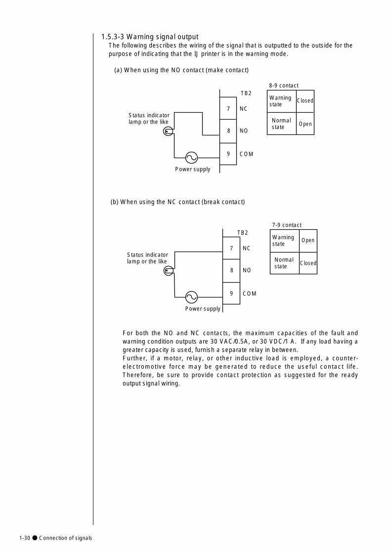
1-30● Connection of signals
1.5.3-3 Warning signal outputThe following describes the wiring of the signal that is outputted to the outside for thepurpose of indicating that the IJ printer is in the warning mode.
(a) When using the NO contact (make contact)
(b) When using the NC contact (break contact)
For both the NO and NC contacts, the maximum capacities of the fault andwarning condition outputs are 30 VAC/0.5A, or 30 VDC/1 A. If any load having agreater capacity is used, furnish a separate relay in between.Further, if a motor, relay, or other inductive load is employed, a counter-electromotive force may be generated to reduce the useful contact life.Therefore, be sure to provide contact protection as suggested for the readyoutput signal wiring.
7
8
9
NC
NO
COM
Power supply
Status indicator lamp or the like
TB28-9 contact
Warning state
Closed
Normal state Open
7
8
9
NC
NO
COM
Power supply
Status indicator lamp or the like
TB27-9 contact
Warning state
ClosedNormal state
Open
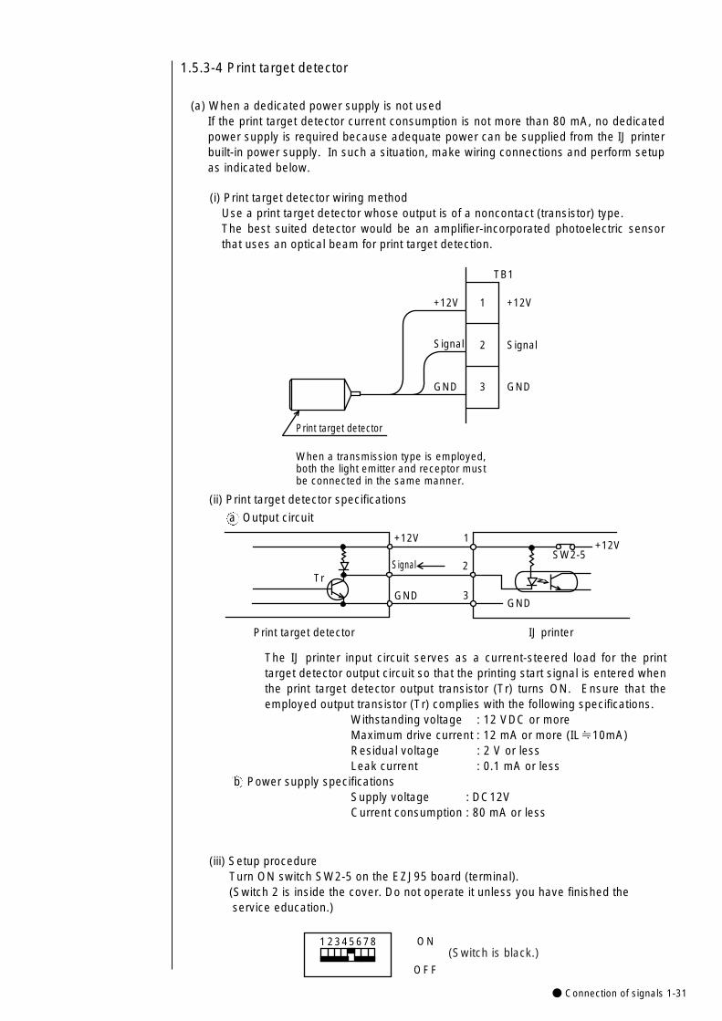
● Connection of signals 1-31
1.5.3-4 Print target detector
(a) When a dedicated power supply is not usedIf the print target detector current consumption is not more than 80 mA, no dedicatedpower supply is required because adequate power can be supplied from the IJ printerbuilt-in power supply. In such a situation, make wiring connections and perform setupas indicated below.
(i) Print target detector wiring methodUse a print target detector whose output is of a noncontact (transistor) type. The best suited detector would be an amplifier-incorporated photoelectric sensorthat uses an optical beam for print target detection.
(ii) Print target detector specifications
a Output circuit
The IJ printer input circuit serves as a current-steered load for the printtarget detector output circuit so that the printing start signal is entered whenthe print target detector output transistor (Tr) turns ON. Ensure that theemployed output transistor (Tr) complies with the following specifications.
Withstanding voltage : 12 VDC or moreMaximum drive current : 12 mA or more (IL≒10mA)Residual voltage : 2 V or lessLeak current : 0.1 mA or less
b Power supply specificationsSupply voltage : DC12VCurrent consumption : 80 mA or less
Print target detector
TB1
+12V
Signal
GND
+12V
Signal
GND
1
2
3
When a transmission type is employed, both the light emitter and receptor must be connected in the same manner.
GND
Tr
GND
+12V+12V
Signal
1
2
3
SW2-5
Print target detector IJ printer
(iii) Setup procedureTurn ON switch SW2-5 on the EZJ95 board (terminal).(Switch 2 is inside the cover. Do not operate it unless you have finished the service education.)
1 2345678 ON
OFF
(Switch is black.)
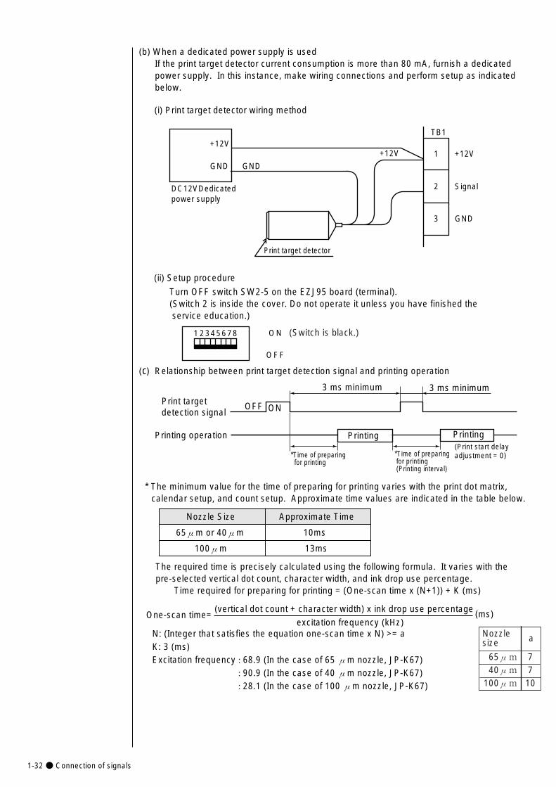
1-32● Connection of signals
(b) When a dedicated power supply is usedIf the print target detector current consumption is more than 80 mA, furnish a dedicatedpower supply. In this instance, make wiring connections and perform setup as indicatedbelow.
(i) Print target detector wiring method
(ii) Setup procedure
Turn OFF switch SW2-5 on the EZJ95 board (terminal).(Switch 2 is inside the cover. Do not operate it unless you have finished the service education.)
Print target detector
+12V
GND GND
DC12VDedicated power supply
+12V
TB1
+12V
Signal
GND
1
2
3
1 2345678 ON
OFF
(Switch is black.)
* The minimum value for the time of preparing for printing varies with the print dot matrix,calendar setup, and count setup. Approximate time values are indicated in the table below.
One-scan time= (vertical dot count + character width) x ink drop use percentage
excitation frequency (kHz)N: (Integer that satisfies the equation one-scan time x N) >= aK: 3 (ms)Excitation frequency : 68.9 (In the case of 65 μm nozzle, JP-K67) : 90.9 (In the case of 40 μm nozzle, JP-K67) : 28.1 (In the case of 100 μm nozzle, JP-K67)
(ms)
Nozzlesize a
65μm 7 40μm 7100μm 10
The required time is precisely calculated using the following formula. It varies with thepre-selected vertical dot count, character width, and ink drop use percentage.
Time required for preparing for printing = (One-scan time x (N+1)) + K (ms)
Printing Printing
3 ms minimum 3 ms minimum
OFF ON
*Time of preparing for printing (Printing interval)
(Print start delay adjustment = 0)
Print target detection signal
Printing operation
*Time of preparing for printing
(c) Relationship between print target detection signal and printing operation
Nozzle Size Approximate Time
65μm or 40μm 10ms
100μm 13ms
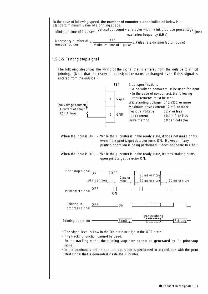
● Connection of signals 1-33
1.5.3-5 Printing stop signal
The following describes the wiring of the signal that is entered from the outside to inhibitprinting. (Note that the ready output signal remains unchanged even if this signal isentered from the outside.)
Input specifications・A no-voltage contact must be used for input.・In the case of noncontact, the following
requirements must be met.Withstanding voltage : 12 VDC or moreMaximum drive current: 12 mA or moreResidual voltage : 2 V or lessLeak current : 0.1 mA or lessDrive method : Open collector
When the input is ON - While the IJ printer is in the ready state, it does not make prints even if the print target detector turns ON. However, if any printing operation is being performed, it does not come to a halt.
When the input is OFF - While the IJ printer is in the ready state, it starts making printsupon print target detector ON.
(No-voltage contact) A current of about 12 mA flows.
TB1
Signal
GND
4
5
Print stop signalON OFF
50 ms or more0 ms ormore
OFF
OFF
Printing
ON
ON
50 ms or more
20 ms or more
50 ms or more
Printing [No printing]
Print start signal
Printing-in-progress signal
Printing operation
・The signal level is Low in the ON state or High in the OFF state.・The tracking function cannot be used.
In the tracking mode, the printing stop time cannot be generated by the print stopsignal.
・In the continuous print mode, the operation is performed in accordance with the printstart signal that is generated inside the IJ printer.
In the case of following speed, the number of encoder pulses indicated below is a standard minimum value of a printing space.
Minimum time of 1 pulse=
Necessary number of encoder pulses
K+aMinimum time of 1 pulse
= x Pulse rate division factor (pulse)
(vertical dot count + character width) x ink drop use percentage
excitation frequency (kHz) (ms)
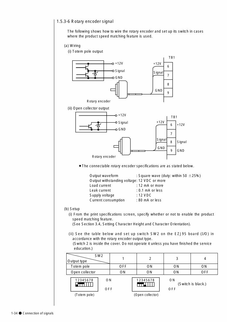
1-34● Connection of signals
1.5.3-6 Rotary encoder signal
The following shows how to wire the rotary encoder and set up its switch in caseswhere the product speed matching feature is used.
(a) Wiring
(i) Totem pole output
6
7
8
9
TB1
+12V
Signal
GND
+12V
Signal
GND
Rotary encoder
(ii) Open collector output
¡The connectable rotary encoder specifications are as stated below.
Output waveform : Square wave (duty: within 50 ±25%)Output withstanding voltage: 12 VDC or moreLoad current : 12 mA or moreLeak current : 0.1 mA or lessSupply voltage : 12 VDC Current consumption : 80 mA or less
6
7
8
9
TB1
+12V
Signal
GND
+12V
Signal
GND
Rotary encoder
+12V
Signal
GND
1 2 3 4
(b) Setup(i) From the print specifications screen, specify whether or not to enable the product
speed matching feature. (See Section 3.4, Setting Character Height and Character Orientation).
(ii) See the table below and set up switch SW2 on the EZJ95 board (I/O) inaccordance with the rotary encoder output type.(Switch 2 is inside the cover. Do not operate it unless you have finished the service education.)
SW2Output type
Totem pole OFF ON ON ON
Open collector ON ON ON OFF
(Totem pole)
1 2345678 ON
OFF
(Open collector)
1 2345678 ON
OFF(Switch is black.)
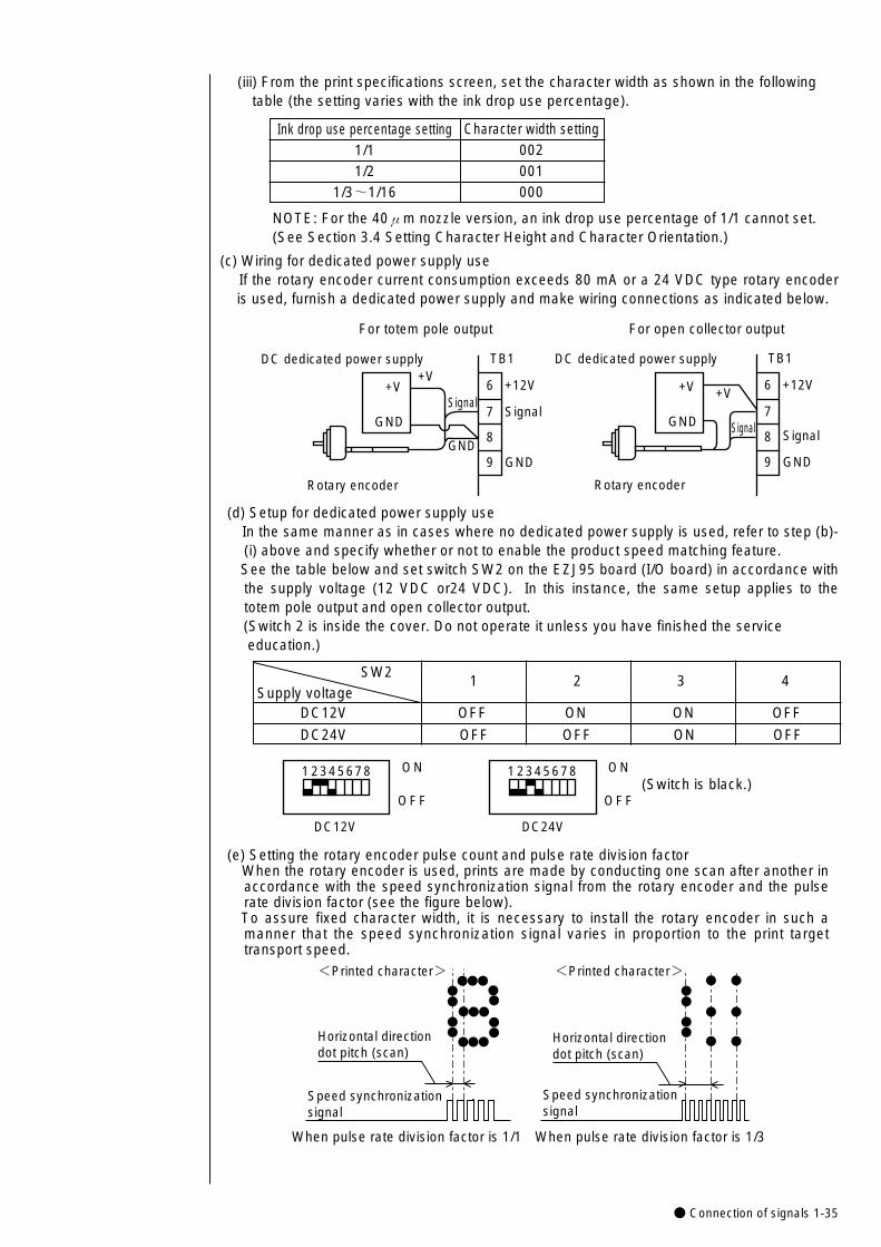
● Connection of signals 1-35
(iii) From the print specifications screen, set the character width as shown in the followingtable (the setting varies with the ink drop use percentage).
DC dedicated power supply+V
+V
GNDSignal
GND
Rotary encoder
GND
6
7
8
9
TB1
+12V
Signal
DC dedicated power supply
+V+V
GND Signal
Rotary encoder
GND
6
7
8
9
TB1
+12V
Signal
For totem pole output For open collector output
(c) Wiring for dedicated power supply useIf the rotary encoder current consumption exceeds 80 mA or a 24 VDC type rotary encoderis used, furnish a dedicated power supply and make wiring connections as indicated below.
(d) Setup for dedicated power supply useIn the same manner as in cases where no dedicated power supply is used, refer to step (b)-(i) above and specify whether or not to enable the product speed matching feature. See the table below and set switch SW2 on the EZJ95 board (I/O board) in accordance withthe supply voltage (12 VDC or24 VDC). In this instance, the same setup applies to thetotem pole output and open collector output.(Switch 2 is inside the cover. Do not operate it unless you have finished the service education.)
1 2 3 4SW2
Supply voltageDC12V OFF ON ON OFF
DC24V OFF OFF ON OFF
DC12V
1 2345678 ON
OFF
DC24V
1 2345678 ON
OFF(Switch is black.)
Character width setting002 001 000
Ink drop use percentage setting1/1 1/2
1/3~1/16
NOTE: For the 40μm nozzle version, an ink drop use percentage of 1/1 cannot set.(See Section 3.4 Setting Character Height and Character Orientation.)
(e) Setting the rotary encoder pulse count and pulse rate division factorWhen the rotary encoder is used, prints are made by conducting one scan after another inaccordance with the speed synchronization signal from the rotary encoder and the pulserate division factor (see the figure below).To assure fixed character width, it is necessary to install the rotary encoder in such amanner that the speed synchronization signal varies in proportion to the print targettransport speed.
Horizontal direction dot pitch (scan)
<Printed character>
Speed synchronization signal
When pulse rate division factor is 1/1
Horizontal direction dot pitch (scan)
<Printed character>
Speed synchronization signal
When pulse rate division factor is 1/3
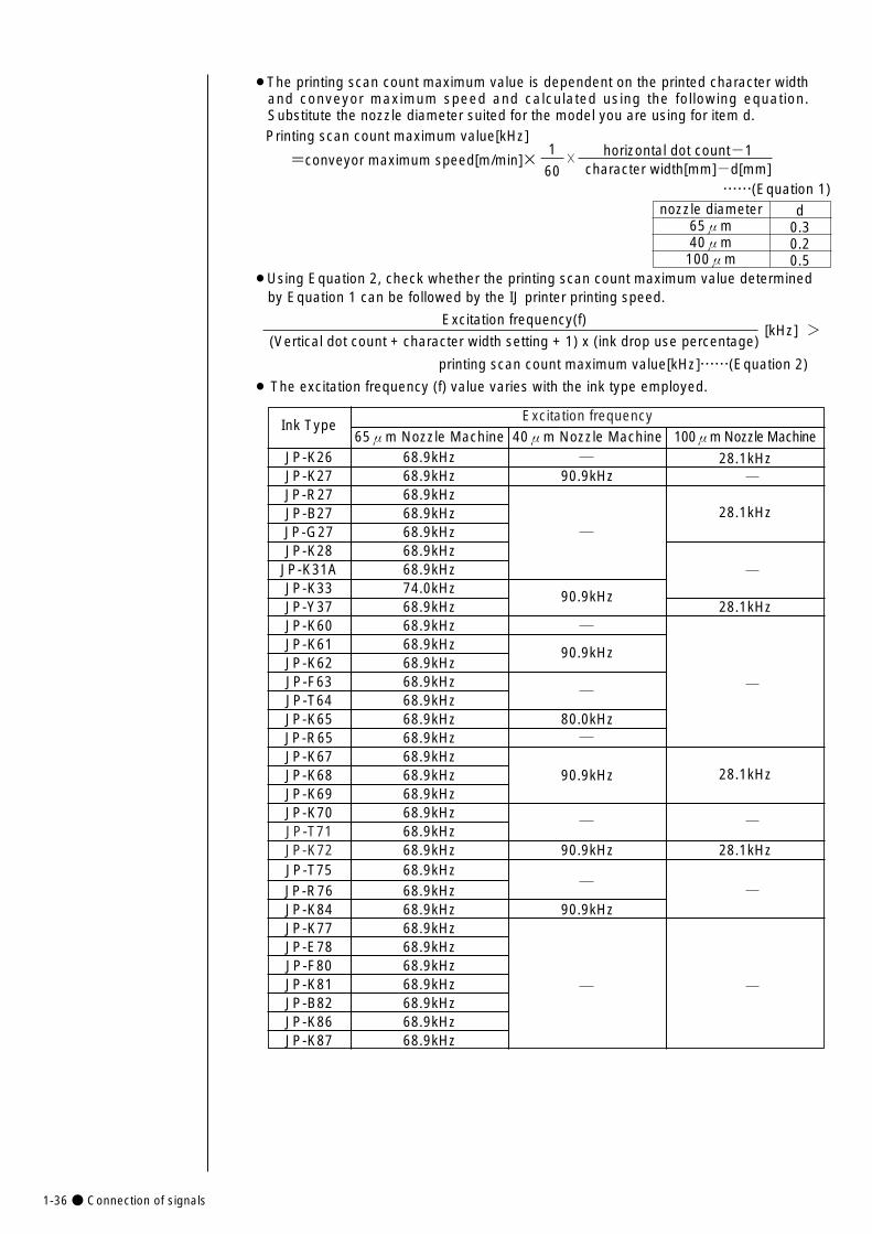
Excitation frequency
JP-T71JP-K72
1-36● Connection of signals
28.1kHz68.9kHz68.9kHz
68.9kHz68.9kHz
68.9kHz68.9kHz68.9kHz68.9kHz68.9kHz68.9kHz
Ink Type
JP-K26
JP-B27JP-G27
JP-K31A
68.9kHz
68.9kHz
68.9kHzJP-K27JP-R27
JP-K33
68.9kHz68.9kHz 90.9kHz
74.0kHz 90.9kHzJP-Y37 68.9kHz
68.9kHz
¡The printing scan count maximum value is dependent on the printed character widthand conveyor maximum speed and calculated using the following equation.Substitute the nozzle diameter suited for the model you are using for item d.Printing scan count maximum value[kHz]
1
60horizontal dot count-1
character width[mm]-d[mm]×
……(Equation 1)
¡Using Equation 2, check whether the printing scan count maximum value determinedby Equation 1 can be followed by the IJ printer printing speed.
Excitation frequency(f)
(Vertical dot count + character width setting + 1) x (ink drop use percentage)[kHz] >
¡ The excitation frequency (f) value varies with the ink type employed.
65μm Nozzle Machine 40μm Nozzle Machine 100μm Nozzle Machine
28.1kHz
28.1kHz
28.1kHz
JP-K60
JP-F63JP-T64JP-K65 80.0kHzJP-R65
JP-K61JP-K62
JP-K67
90.9kHz
90.9kHz
90.9kHz
90.9kHz
28.1kHz
JP-K28 68.9kHz
JP-K68JP-K69
68.9kHzJP-K7068.9kHz68.9kHz
=conveyor maximum speed[m/min]×
printing scan count maximum value[kHz]……(Equation 2)
nozzle diameter65μm40μm
100μm
d0.30.20.5
68.9kHzJP-T7568.9kHzJP-R7668.9kHzJP-K8468.9kHzJP-K7768.9kHzJP-E7868.9kHzJP-F8068.9kHzJP-K8168.9kHzJP-B8268.9kHzJP-K8668.9kHzJP-K87
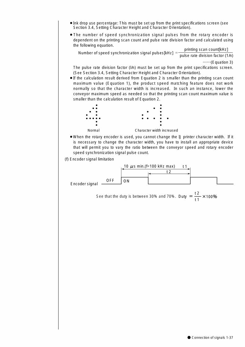
● Connection of signals 1-37
Normal Character width increased
¡When the rotary encoder is used, you cannot change the IJ printer character width. If itis necessary to change the character width, you have to install an appropriate devicethat will permit you to vary the ratio between the conveyor speed and rotary encoderspeed synchronization signal pulse count.
¡The number of speed synchronization signal pulses from the rotary encoder isdependent on the printing scan count and pulse rate division factor and calculated usingthe following equation.
Number of speed synchronization signal pulses[kHz] =
……(Equation 3)The pulse rate division factor (l/n) must be set up from the print specifications screen.(See Section 3.4, Setting Character Height and Character Orientation).
¡If the calculation result derived from Equation 2 is smaller than the printing scan countmaximum value (Equation 1), the product speed matching feature does not worknormally so that the character width is increased. In such an instance, lower theconveyor maximum speed as needed so that the printing scan count maximum value issmaller than the calculation result of Equation 2.
printing scan count[kHz]
pulse rate division factor (1/n)
10 μs min.(f=100 kHz max)t 2
OFF ONEncoder signal
t 1
Duty t 2
t 1×100%=See that the duty is between 30% and 70%.
(f) Encoder signal limitation
¡Ink drop use percentage: This must be set up from the print specifications screen (seeSection 3.4, Setting Character Height and Character Orientation).
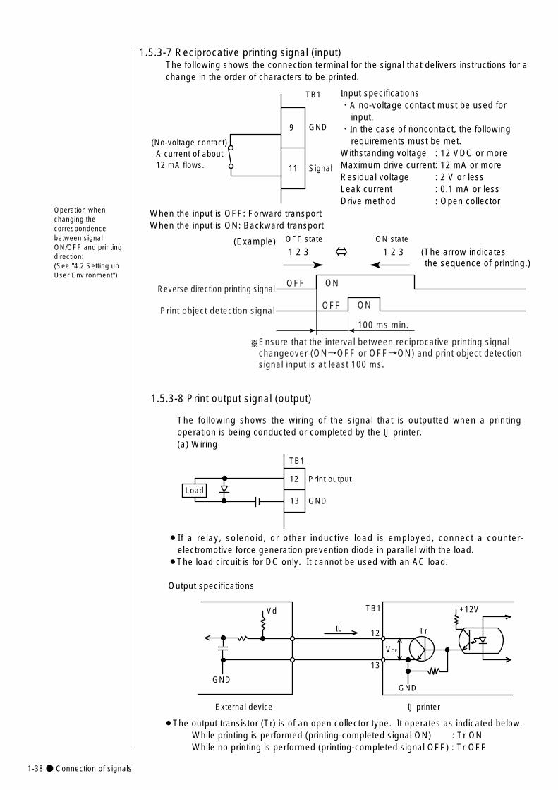
1-38● Connection of signals
1.5.3-8 Print output signal (output)
The following shows the wiring of the signal that is outputted when a printingoperation is being conducted or completed by the IJ printer.(a) Wiring
TB1
12
13 GND
Print outputLoad
¡If a relay, solenoid, or other inductive load is employed, connect a counter-electromotive force generation prevention diode in parallel with the load.
¡The load circuit is for DC only. It cannot be used with an AC load.
Output specifications
GND
Vd
IL
VCE
+12V
Tr
GND
IJ printer External device
TB1
12
13
1.5.3-7 Reciprocative printing signal (input)The following shows the connection terminal for the signal that delivers instructions for achange in the order of characters to be printed.
When the input is OFF: Forward transportWhen the input is ON: Backward transport
1 2 3 1 2 3 (The arrow indicates the sequence of printing.)
OFF state ON state
Input specifications・A no-voltage contact must be used for
input.・In the case of noncontact, the following
requirements must be met.Withstanding voltage : 12 VDC or moreMaximum drive current: 12 mA or moreResidual voltage : 2 V or lessLeak current : 0.1 mA or lessDrive method : Open collector
(No-voltage contact) A current of about 12 mA flows.
TB1
GND
Signal
9
11
(Example)
�
�※�
��
100 ms min.
Reverse direction printing signal
Print object detection signal
Ensure that the interval between reciprocative printing signal changeover (ON→OFF or OFF→ON) and print object detection signal input is at least 100 ms.
OFF
OFF
ON
ON
Operation whenchanging thecorrespondencebetween signalON/OFF and printingdirection:(See "4.2 Setting upUser Environment")
¡The output transistor (Tr) is of an open collector type. It operates as indicated below.While printing is performed (printing-completed signal ON) : Tr ONWhile no printing is performed (printing-completed signal OFF) : Tr OFF
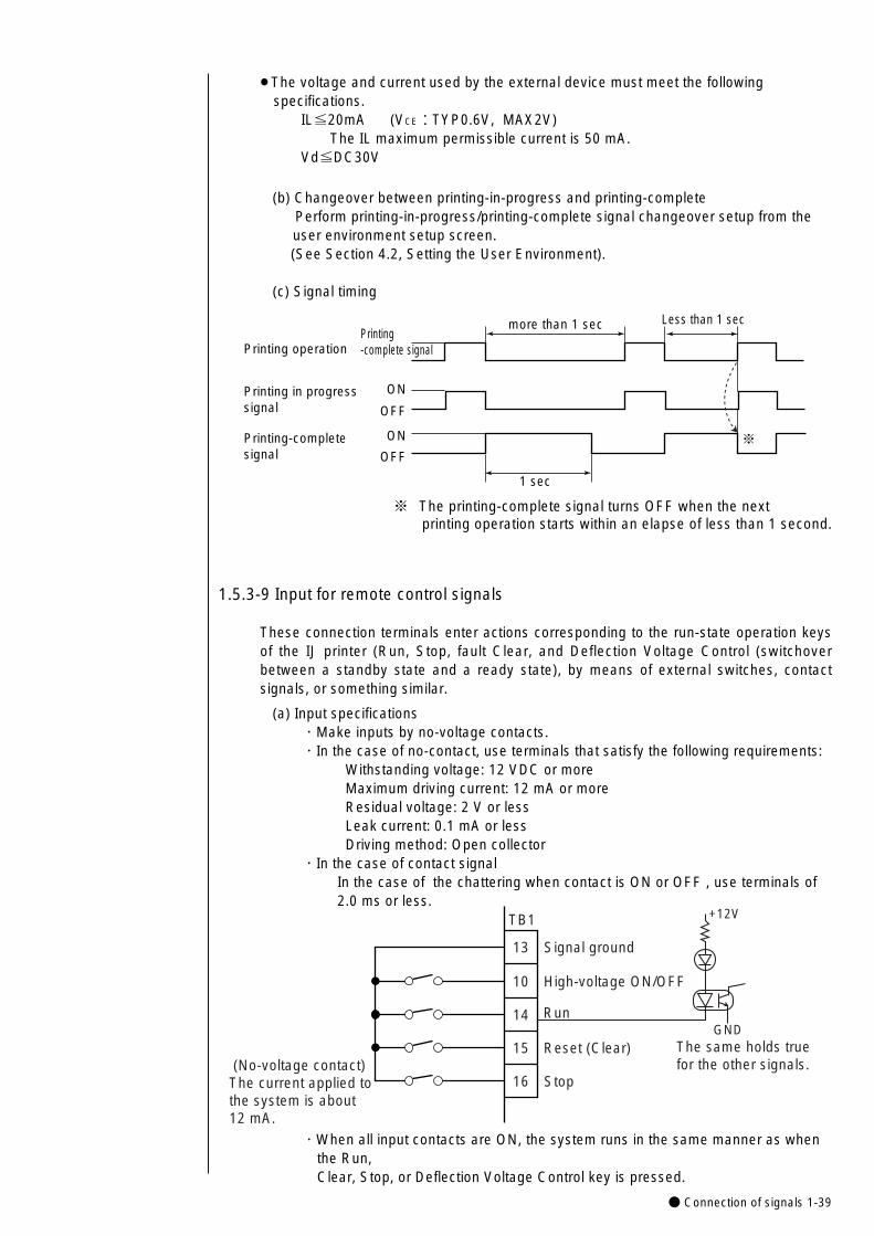
● Connection of signals 1-39
1.5.3-9 Input for remote control signals
These connection terminals enter actions corresponding to the run-state operation keysof the IJ printer (Run, Stop, fault Clear, and Deflection Voltage Control (switchoverbetween a standby state and a ready state), by means of external switches, contactsignals, or something similar.
(a) Input specifications ・Make inputs by no-voltage contacts. ・In the case of no-contact, use terminals that satisfy the following requirements:
Withstanding voltage: 12 VDC or more Maximum driving current: 12 mA or more Residual voltage: 2 V or less Leak current: 0.1 mA or less Driving method: Open collector
・In the case of contact signalIn the case of the chattering when contact is ON or OFF , use terminals of 2.0 ms or less.
TB1
13
16
15
14
10
(No-voltage contact) The current applied tothe system is about 12 mA.
Signal ground
High-voltage ON/OFF
Run
Reset (Clear)
Stop
+12V
GNDThe same holds true for the other signals.
・When all input contacts are ON, the system runs in the same manner as when the Run, Clear, Stop, or Deflection Voltage Control key is pressed.
¡The voltage and current used by the external device must meet the following specifications.
IL≦20mA (VCE:TYP0.6V, MAX2V)The IL maximum permissible current is 50 mA.
Vd≦DC30V
(b) Changeover between printing-in-progress and printing-completePerform printing-in-progress/printing-complete signal changeover setup from the user environment setup screen. (See Section 4.2, Setting the User Environment).
(c) Signal timing
Printing operation
Printing in progresssignal
Printing-complete signal
1 sec
OFF
ON
Printing-complete signal
OFF
ON
Less than 1 sec
※�
※ The printing-complete signal turns OFF when the next printing operation starts within an elapse of less than 1 second.
more than 1 sec

1-40● Connection of signals
(b-2) "High-voltage ON/OFF signal"1 For inputting the "high-voltage ON/OFF signal" in succession, a certain OFF
duration is required. When t2 is 10 ms or less, the OFF status is not detected andthe signal cannot be accepted.
t2
High-voltage ON/OFF signal
2 The time t3 from an input of "high-voltage ON/OFF signal" till a change of statue is 3 seconds or less. (Standby -> Print Enable)
t3
High-voltage ON/OFF signal
Print Enable signal
3 For turning on the "high-voltage ON/OFF signal", the status must be confirmedbeforehand. If the "high-voltage ON/OFF signal" is turned on by mistake duringprinting, this printing, which may be in progress, is aborted and the print enablestatus is switched over to the standby status.For prevention against a print error, input a signal in the status where printing is notin progress.
4 If you want to change the contents of print when the product speed matchingfunction is used and the transfer is stopped during printing, this signal permitsswitching the status over to the standby status to allow you to change the contentsof print.
t4 is 100ms or less. ( Print Enable -> Standby)
t4
High-voltage ON/OFF signal
Print Enable signal
t1
Remote signal
(b) Judgement conditions
(b-1) Remote signals in general
1 The ON duration of the remote signal is 100 ms or more.
2 Don't turn on multiple remote signals at a time.If multiple signals are turned on, they cannot be accepted.
3 In the following cases, no signal is accepted.
i The confirmation window is open.
ii The circulation control screen is opened by the maintenance function.
iii The touch screen setup screen is opened by the auxiliary function.
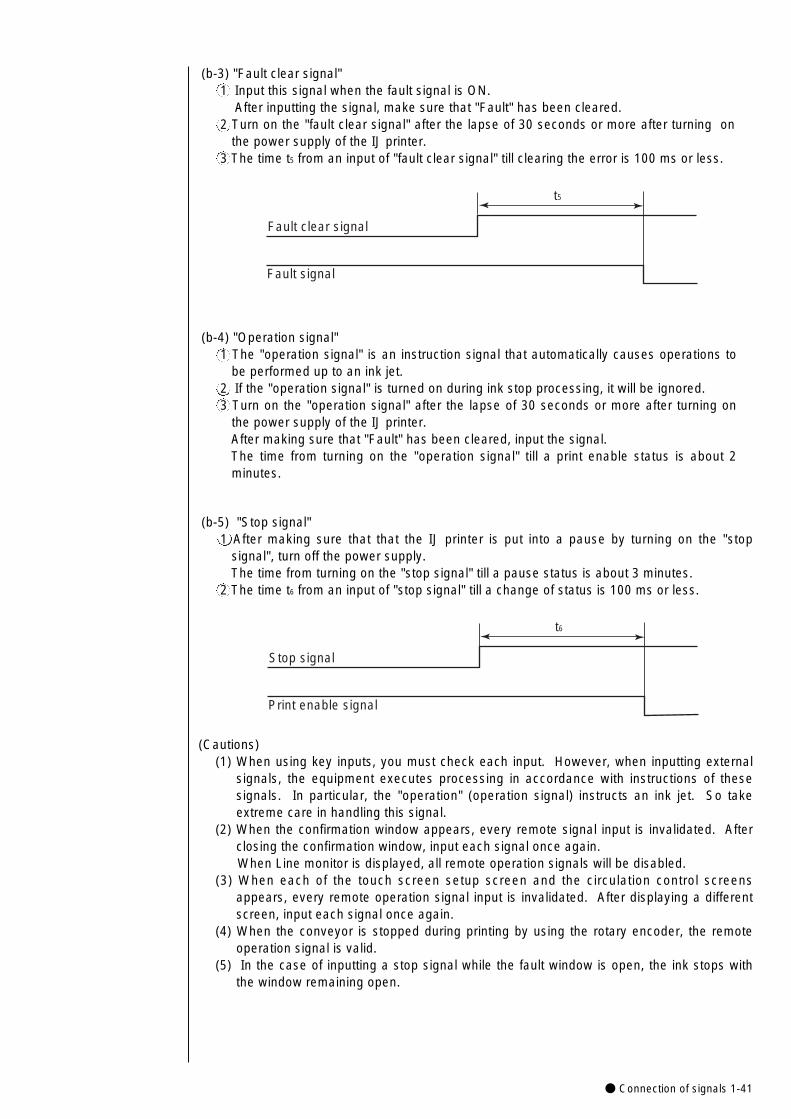
● Connection of signals 1-41
(b-5) "Stop signal"1 After making sure that that the IJ printer is put into a pause by turning on the "stop
signal", turn off the power supply.The time from turning on the "stop signal" till a pause status is about 3 minutes.
2 The time t6 from an input of "stop signal" till a change of status is 100 ms or less.
t6
Stop signal
Print enable signal
(Cautions)(1) When using key inputs, you must check each input. However, when inputting external
signals, the equipment executes processing in accordance with instructions of thesesignals. In particular, the "operation" (operation signal) instructs an ink jet. So takeextreme care in handling this signal.
(2) When the confirmation window appears, every remote signal input is invalidated. Afterclosing the confirmation window, input each signal once again.When Line monitor is displayed, all remote operation signals will be disabled.
(3) When each of the touch screen setup screen and the circulation control screensappears, every remote operation signal input is invalidated. After displaying a differentscreen, input each signal once again.
(4) When the conveyor is stopped during printing by using the rotary encoder, the remoteoperation signal is valid.
(5) In the case of inputting a stop signal while the fault window is open, the ink stops withthe window remaining open.
(b-3) "Fault clear signal"1 Input this signal when the fault signal is ON.
After inputting the signal, make sure that "Fault" has been cleared.2 Turn on the "fault clear signal" after the lapse of 30 seconds or more after turning on
the power supply of the IJ printer.3 The time t5 from an input of "fault clear signal" till clearing the error is 100 ms or less.
t5
Fault clear signal
Fault signal
(b-4) "Operation signal"1 The "operation signal" is an instruction signal that automatically causes operations to
be performed up to an ink jet.2 If the "operation signal" is turned on during ink stop processing, it will be ignored.3 Turn on the "operation signal" after the lapse of 30 seconds or more after turning on
the power supply of the IJ printer.After making sure that "Fault" has been cleared, input the signal. The time from turning on the "operation signal" till a print enable status is about 2minutes.
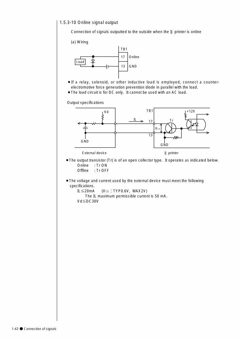
1-42● Connection of signals
1.5.3-10 Online signal output
Connection of signals outputted to the outside when the IJ printer is online
(a) Wiring
TB1
17
13 GND
OnlineLoad
¡If a relay, solenoid, or other inductive load is employed, connect a counter-electromotive force generation prevention diode in parallel with the load.
¡The load circuit is for DC only. It cannot be used with an AC load.
Output specifications
GND
Vd
IL
VCE
+12V
Tr
GND
IJ printer External device
TB1
17
13
¡The output transistor (Tr) is of an open collector type. It operates as indicated below.Online : Tr ONOffline : Tr OFF
¡The voltage and current used by the external device must meet the following specifications.
IL≦20mA (VCE:TYP0.6V, MAX2V)The IL maximum permissible current is 50 mA.
Vd≦DC30V
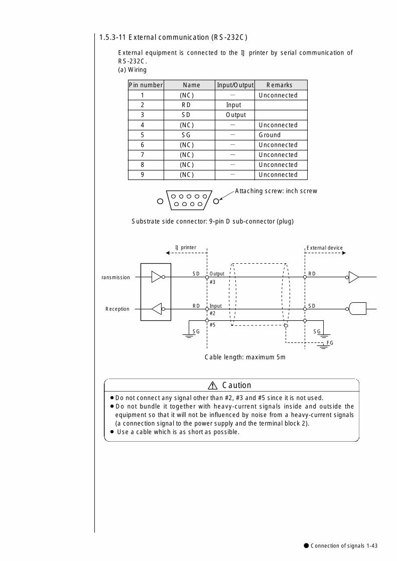
● Connection of signals 1-43
1.5.3-11 External communication (RS-232C)
External equipment is connected to the IJ printer by serial communication ofRS-232C.(a) Wiring
Attaching screw: inch screw
Substrate side connector: 9-pin D sub-connector (plug)
IJ printer
SD Output
#3
RD Input#2
SG
External device
RD
SD
SG
FG
#5
ransmission
Reception
Cable length: maximum 5m
Caution¡Do not connect any signal other than #2, #3 and #5 since it is not used.¡Do not bundle it together with heavy-current signals inside and outside the
equipment so that it will not be influenced by noise from a heavy-current signals(a connection signal to the power supply and the terminal block 2).
¡ Use a cable which is as short as possible.
Pin number Name Input/Output Remarks
1 (NC) - Unconnected
2 RD Input
3 SD Output
4 (NC) - Unconnected
5 SG - Ground
6 (NC) - Unconnected
7 (NC) - Unconnected
8 (NC) - Unconnected
9 (NC) - Unconnected
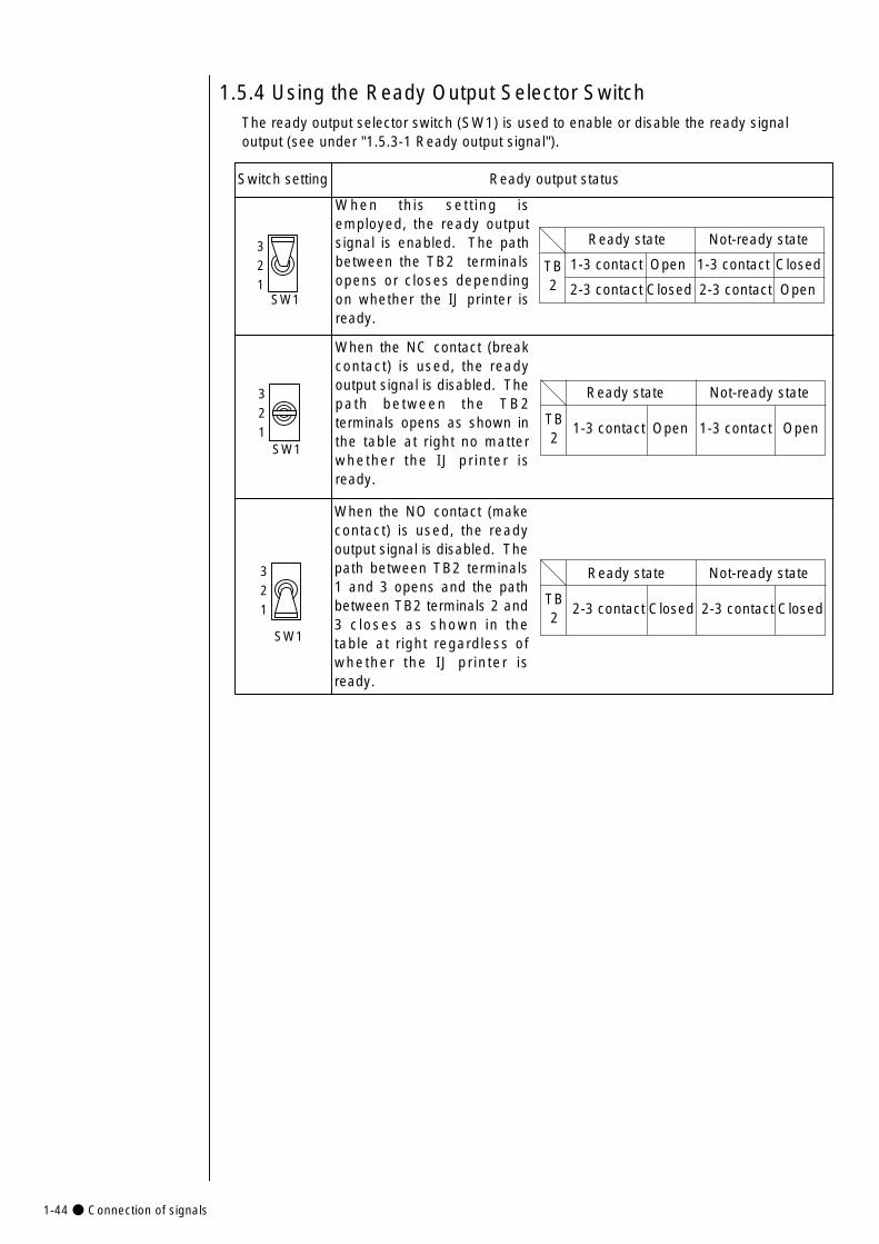
1-44● Connection of signals
The ready output selector switch (SW1) is used to enable or disable the ready signaloutput (see under "1.5.3-1 Ready output signal").
Switch setting Ready output status
1.5.4 Using the Ready Output Selector Switch
321
SW1
When this sett ing isemployed, the ready outputsignal is enabled. The pathbetween the TB2 terminalsopens or closes dependingon whether the IJ printer isready.
Ready state Not-ready state
1-3 contact Open 1-3 contact Closed
2-3 contact Closed 2-3 contact Open
TB2
Ready state Not-ready state
1-3 contact Open 1-3 contact OpenTB2
Ready state Not-ready state
2-3 contact Closed 2-3 contact ClosedTB2
When the NO contact (makecontact) is used, the readyoutput signal is disabled. Thepath between TB2 terminals1 and 3 opens and the pathbetween TB2 terminals 2 and3 closes as shown in thetable at right regardless ofwhether the IJ printer isready.
When the NC contact (breakcontact) is used, the readyoutput signal is disabled. Thepath between the TB2terminals opens as shown inthe table at right no matterwhether the IJ printer isready.
321
SW1
321
SW1

● Startup 2-1
1
2. Basic Operating Procedures
2.1 Startup
¡The ink and makeup ink employed contains organic solvents. When handling them, wear protective gloves and safety goggles to avoid direct skin contact.
¡A touch key incorporated LCD is employed. When manipulating the keys, do not apply excessive force to them.
¡If the system becomes inoperative, press the power switch to OFF. When turning the power switch back ON to use the printer,see Section 10, Emergency Procedures.
CAUTION
Press the power ON/OFF switch to turn ON the power.
》
Status:Stop Com=0
Column 1 Column 2 Column 3
[USE BY・・・・ ] [YY.MM.DD・・・] [・・・・・・・・・・]
[YY.MM.DD・・・] [MFG D A T E・・ ] [・・・・・・・・・・]
[ABC・・・・・・・] [CCCC・・・・・・] [・・・・・・・・・・]
[・・・・・・・・・・] [・・・・・・・・・・] [・・・・・・・・・・]
《
USE BYMFG DATE
ABC11.07.07
0001
11.07.07
The current operating status is indicated (see Section 2.3.2, Status, for details).
The printings are described.
The print layout is indicated.
Print description 2011.07.07 12:45Message name[AAAAAAAAAAAA] Start
upShutdown
Manual
Prev.col.
Next col.
Selectmessage
Savemessage Menu
Print line setup
Editmessage
Print format
Print spec.
Print layout
CommOn/Off
The following print description screen opens.
2.1.1 Starting an operation
¡It takes about 50 seconds for the above screen to open.
¡Verify that the print descriptions are entered.
Press.
For print description
input, see Section 3,
Editing Print Data and
Printing.
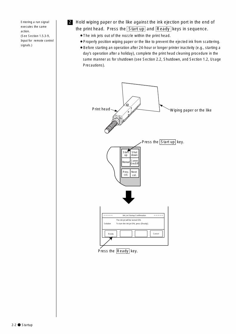
2-2● Startup
2 Hold wiping paper or the like against the ink ejection port in the end of
the print head. Press the Start up and Ready keys in sequence.
¡The ink jets out of the nozzle within the print head.
¡Properly position wiping paper or the like to prevent the ejected ink from scattering.
¡Before starting an operation after 24-hour or longer printer inactivity (e.g., starting a
day's operation after a holiday), complete the print head cleaning procedure in the
same manner as for shutdown (see Section 2.2, Shutdown, and Section 1.2, Usage
Precautions).
Wiping paper or the likePrint head
The ink jet will be turned ON.
Solution To turn the ink jet ON, press [Ready].
Ready Cancel
===== Ink Jet Startup Confirmation =====
Startup
Shutdown
Manual
Prev.col.
Next col.
Press the Start up key.
Press the Ready key.
CommOm/Off
Entering a run signal
executes the same
action.
(See Section 1.5.3-9,
Input for remote control
signals.)
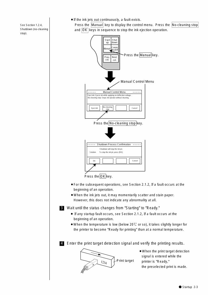
● Startup 2-3
4
3
¡For the subsequent operations, see Section 2.1.2, If a fault occurs at the
beginning of an operation.
¡When the ink jets out, it may momentarily scatter and stain paper.
However, this does not indicate any abnormality at all.
Manual Control Menu
===== Manual Control Menu =====
Press the OK key.
Shutdown will stop the ink jet.
Solution To stop the ink jet, press [OK].
OK Cancel
===== Shutdown Process Confirmation =====
Startup
Shutdown
Manual
Prev.col.
Next col.
Press the Manual key.
Eject ink: Ejects ink while applying no deflection voltage.No-cleaning stop: Stops ink ejection without cleaning.
Eject ink No-cleaning
stopCancel
Press the No-cleaning stop key.
CommOn/Off
¡If the ink jets out continuously, a fault exists.
Press the Manual key to display the control menu. Press the No-cleaning stop
and OK keys in sequence to stop the ink ejection operation.
Wait until the status changes from "Starting" to "Ready."
¡ If any startup fault occurs, see Section 2.1.2, If a fault occurs at the
beginning of an operation.
¡When the temperature is low (below 20℃ or so), it takes slightly longer for
the printer to become "Ready for printing" than at a normal temperature.
Enter the print target detection signal and verify the printing results.
1234Print target
¡When the print target detection
signal is entered while the
printer is "Ready,"
the preselected print is made.
See Section 1.2.4,
Shutdown (no-cleaning
stop).
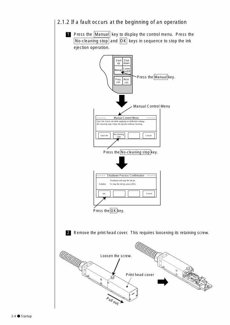
2-4● Startup
1
2.1.2 If a fault occurs at the beginning of an operation
Press the Manual key to display the control menu. Press the
No-cleaning stop and OK keys in sequence to stop the ink
ejection operation.
Manual Control Menu
===== Manual Control Menu =====
Press the OK key.
Shutdown will stop the ink jet.
Solution To stop the ink jet, press [OK].
OK Cancel
===== Shutdown Process Confirmation =====
Startup
Shutdown
Manual
Prev.col.
Next col.
Press the Manual key.
Eject ink: Ejects ink while applying no deflection voltage.No-cleaning stop: Stops ink ejection without cleaning.
Eject ink No-cleaning
stopCancel
Press the No-cleaning stop key.
CommOn/Off
Remove the print head cover. This requires loosening its retaining screw.2
Pull out.
Loosen the screw.
Print head cover
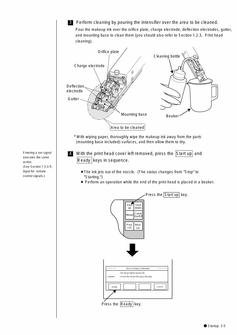
● Startup 2-5
4
3
Pour the makeup ink over the orifice plate, charge electrode, deflection electrodes, gutter,
and mounting base to clean them (you should also refer to Section 1.2.3, Print head
cleaning).
Orifice plate
Charge electrode
Deflectionelectrode
Mounting base Beaker
Area to be cleaned
Cleaning bottle
Gutter
* With wiping paper, thoroughly wipe the makeup ink away from the parts (mounting base included) surfaces, and then allow them to dry.
Perform cleaning by pouring the intensifier over the area to be cleaned.
With the print head cover left removed, press the Start up and
Ready keys in sequence.
¡The ink jets out of the nozzle. (The status changes from "Stop" to "Starting.")
¡ Perform an operation while the end of the print head is placed in a beaker.
The ink jet will be turned ON.
Solution To turn the ink jet ON, press [Ready].
Ready Cancel
===== Ink Jet Startup Confirmation =====
Startup
Shutdown
Manual
Prev.col.
Next col.
Press the Start up key.
Press the Ready key.
CommOm/Off
Entering a run signal
executes the same
action.
(See Section 1.5.3-9,
Input for remote
control signals.)
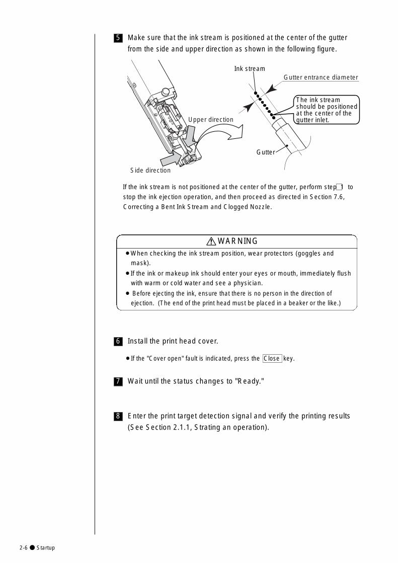
2-6● Startup
8
7
6
5 Make sure that the ink stream is positioned at the center of the gutter
from the side and upper direction as shown in the following figure.
Gutter
Ink stream
The ink stream should be positioned at the center of the gutter inlet.
Side direction
Upper direction
Gutter entrance diameter
If the ink stream is not positioned at the center of the gutter, perform step 1 to
stop the ink ejection operation, and then proceed as directed in Section 7.6,
Correcting a Bent Ink Stream and Clogged Nozzle.
¡When checking the ink stream position, wear protectors (goggles and
mask).
¡If the ink or makeup ink should enter your eyes or mouth, immediately flush
with warm or cold water and see a physician.
¡ Before ejecting the ink, ensure that there is no person in the direction of
ejection. (The end of the print head must be placed in a beaker or the like.)
WARNING
Install the print head cover.
¡If the "Cover open" fault is indicated, press the Close key.
Wait until the status changes to "Ready."
Enter the print target detection signal and verify the printing results
(See Section 2.1.1, Strating an operation).
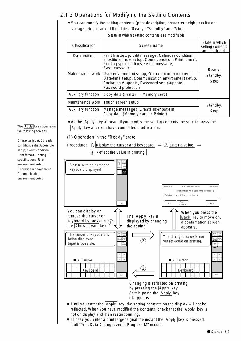
● Startup 2-7
2.1.3 Operations for Modifying the Setting Contents¡You can modify the setting contents (print description, character height, excitation
voltage, etc.) in any of the states "Ready," "Standby" and "Stop."
(1) Operation in the "Ready" state
¡ Until you enter the Apply key, the setting contents on the display will not be reflected. When you have modified the contents, check that the Apply key is not on display and then restart printing.
¡ In case you enter a print terget signal the instant the Apply key is pressed, fault "Print Data Changeover in Progress M" occurs.
Startup
Shutdown
The data entered will be used in the print message.
Solution Press [OK] to accept the data.
OK CancelCancel
changes
===== Data Entry Confirmation =====
Showcursor
1
A state with no cursor or keyboard displayed
The cursor or keyboard is being displayed.Input is possible.
←
→
↑
↓
Keyboard
←Cursor
The changed value is not yet reflected on printing.
←�
→�
↑�
↓�
Keyboard
←Cursor
When you press the Back key to move on, a confirmation screen appears.
You can display or remove the cursor or keyboard by pressing the Show cursor key.
The Apply key is displayed by changing the setting.
Changing is reflected on printing by pressing the Apply key.At this point, the Apply key disappears.
2
3
Manual
Showcursor
Manual
Apply
BackBack
Back
Startup
Shutdown
CommOn/Off
Startup
Shutdown
CommOn/Off
Manual CommOn/Off
Classification Screen name
Data editing Print line setup, Edit message, Calendar condition,substitution rule setup, Count condition, Print format, Printing specifications,Select message, Save message Ready,
Standby, Stop
Auxiliary function
Auxiliary function
Maintenance work
Manage messages, Create user pattern,Copy data (Memory card → Printer)
Standby, Stop
Maintenance work User environment setup, Operation management,Date/time setup, Communication environment setup,Excitation V update, Password setup/update, Password protection
Touch screen setup
Copy data (Printer → Memory card)
State in which setting contents are modifiable
State in which setting contents are modifiable
¡As the Apply key appears if you modify the setting contents, be sure to press the
Apply key after you have completed modification.
Procedure: Display the cursor and keyboard ⇒ Enter a value ⇒
Reflect the value in printing
1 2
3
The Apply key appears on
the following screens.
Character input, Calendar
condition, substitution rule
setup, Count condition,
Print format, Printing
specifications, User
environment setup,
Operation management,
Communication
environment setup.

2-8● Startup
Manual Control Menu
Press the OK key.
Printing will be aborted.
Solution Press [OK] to abort.
OK Cancel
===== Print Abort Confirmation =====
Manual Control Menu
Press the OK key.
The newly created print data will be printed.
Solution Press [OK] to print.
OK Cancel
===== Print Confirmation =====
Press the Manual key.
Switching from "Ready" state to "Standby" state
Switching from "Standby" state to "Ready" state
The control menu appears.
The confirmationscreen opens.
1
2
3
Startup
Shutdown
Manual
Prev.col.
Next col.
===== Manual Control Menu =====Eject ink: Ejects ink while applying no deflection voltage.No-cleaning stop: Stops ink ejection without cleaning.Standby : Switches between the ready - for - printing state and standby state.
Eject ink No-cleaning
stopStandby Cancel
===== Manual Control Menu =====Eject ink: Ejects ink while applying no deflection voltage.No-cleaning stop: Stops ink ejection without cleaning.Ready : Switches between the ready - for - printing state and standby state.
Eject ink No-cleaning
stopCancel
Press the Standby key. Press the Ready key.
CommOn/Off
Ready
¡You can abort the operation by pressing the Cancel key from either the "Manual
Control Menu" screen or the confirmation screen.
(2) Switching between "Ready" state and "Standby" state
¡When the conveyer interlock is put in operation by the Ready output signal, be
careful not to switch to "Standby" state since it will stop the conveyer.
Entering a deflection
voltage ON/OFF signal
executes the same
action.
(See Section 1.5.3-9,
Input for remote
control signals.)
See Section 1.5.3-1,
"Ready output signal".
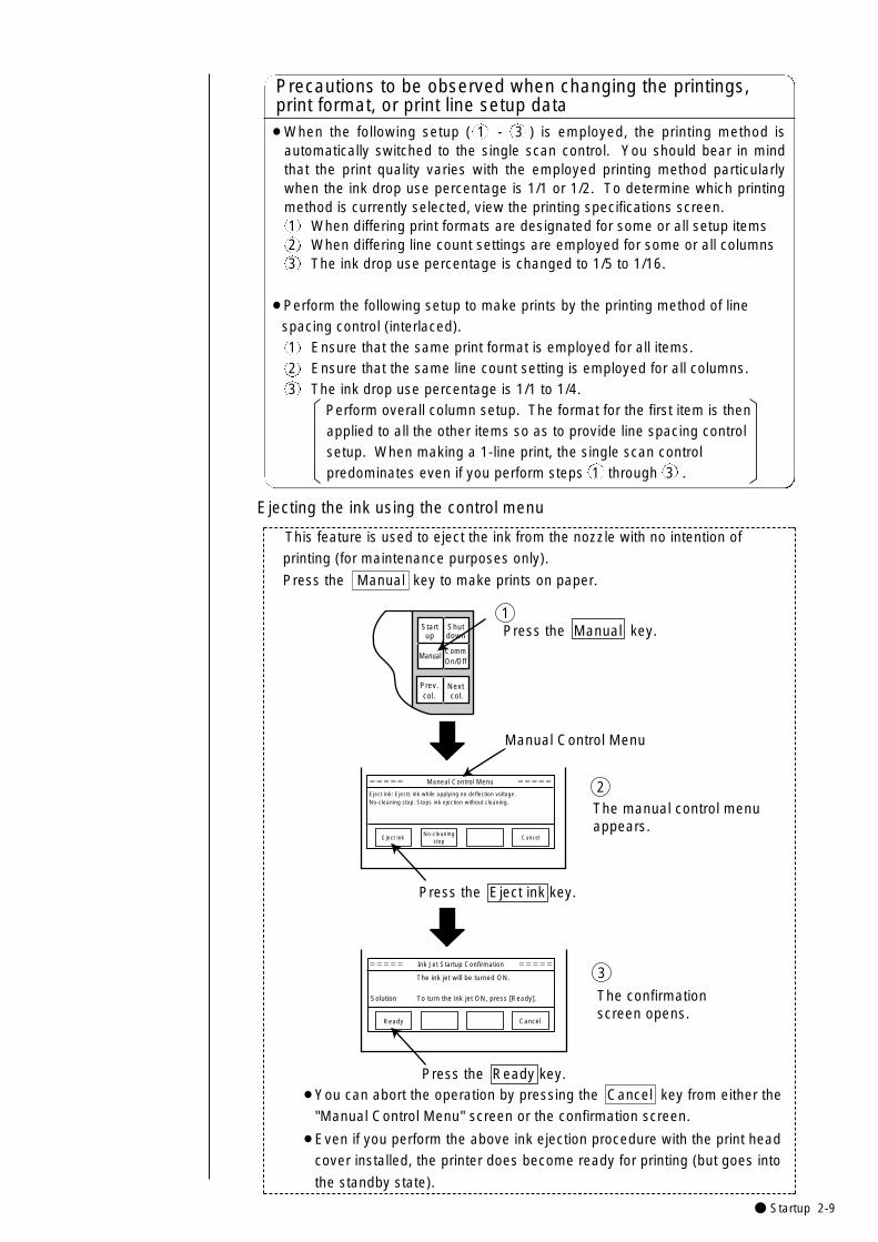
● Startup 2-9
Ejecting the ink using the control menu
The confirmation screen opens.
1
Manual Control Menu
The manual control menu appears.
2
3
Startup
Shutdown
Manual
Prev.col.
Next col.
===== Maneal Control Menu =====
Eject ink: Ejects ink while applying no deflection voltage.No-cleaning stop: Stops ink ejection without cleaning.
Eject ink No-cleaning
stopCancel
The ink jet will be turned ON.
Solution To turn the ink jet ON, press [Ready].
Ready Cancel
===== Ink Jet Startup Confirmation =====
Press the Ready key.
Press the Eject ink key.
Press the Manual key.CommOn/Off
¡You can abort the operation by pressing the Cancel key from either the
"Manual Control Menu" screen or the confirmation screen.
¡Even if you perform the above ink ejection procedure with the print head
cover installed, the printer does become ready for printing (but goes into
the standby state).
¡When the following setup ( 1 - 3 ) is employed, the printing method isautomatically switched to the single scan control. You should bear in mindthat the print quality varies with the employed printing method particularlywhen the ink drop use percentage is 1/1 or 1/2. To determine which printingmethod is currently selected, view the printing specifications screen.1 When differing print formats are designated for some or all setup items2 When differing line count settings are employed for some or all columns3 The ink drop use percentage is changed to 1/5 to 1/16.
¡Perform the following setup to make prints by the printing method of line spacing control (interlaced).1 Ensure that the same print format is employed for all items.2 Ensure that the same line count setting is employed for all columns.3 The ink drop use percentage is 1/1 to 1/4.
Perform overall column setup. The format for the first item is then applied to all the other items so as to provide line spacing control setup. When making a 1-line print, the single scan control predominates even if you perform steps 1 through 3 .
Precautions to be observed when changing the printings, print format, or print line setup data
This feature is used to eject the ink from the nozzle with no intention of
printing (for maintenance purposes only).
Press the Manual key to make prints on paper.
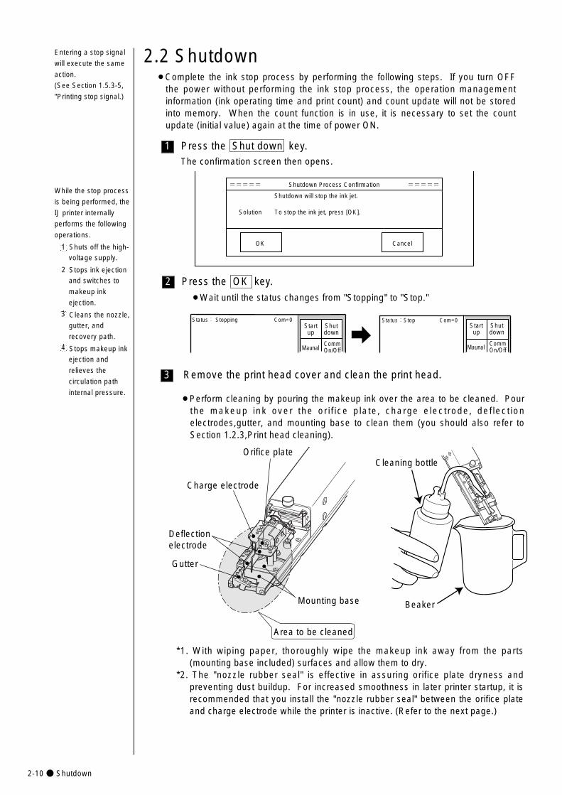
2-10● Shutdown
3
2
1
2.2 Shutdown
Press the Shut down key.The confirmation screen then opens.
Press the OK key.
¡Wait until the status changes from "Stopping" to "Stop."
Remove the print head cover and clean the print head.
===== Shutdown Process Confirmation =====�
Shutdown will stop the ink jet.
Solution To stop the ink jet, press [OK].
OK Cancel
¡Perform cleaning by pouring the makeup ink over the area to be cleaned. Pourthe makeup ink over the orif ice plate, charge electrode, deflectionelectrodes,gutter, and mounting base to clean them (you should also refer toSection 1.2.3,Print head cleaning).
While the stop process
is being performed, the
IJ printer internally
performs the following
operations.
Shuts off the high-
voltage supply.
Stops ink ejection
and switches to
makeup ink
ejection.
Cleans the nozzle,
gutter, and
recovery path.
Stops makeup ink
ejection and
relieves the
circulation path
internal pressure.
2
1
3
4
Status: Stopping Com=0 Status:Stop Com=0Startup
Shutdown
Maunal MaunalCommOn/Off
Startup
Shutdown
CommOn/Off
Orifice plate
Charge electrode
Deflectionelectrode
Mounting base Beaker
Area to be cleaned
Cleaning bottle
Gutter
*1. With wiping paper, thoroughly wipe the makeup ink away from the parts(mounting base included) surfaces and allow them to dry.
*2. The "nozzle rubber seal" is effective in assuring orifice plate dryness andpreventing dust buildup. For increased smoothness in later printer startup, it isrecommended that you install the "nozzle rubber seal" between the orifice plateand charge electrode while the printer is inactive. (Refer to the next page.)
¡Complete the ink stop process by performing the following steps. If you turn OFFthe power without performing the ink stop process, the operation managementinformation (ink operating time and print count) and count update will not be storedinto memory. When the count function is in use, it is necessary to set the countupdate (initial value) again at the time of power ON.
Entering a stop signal
will execute the same
action.
(See Section 1.5.3-5,
"Printing stop signal.)
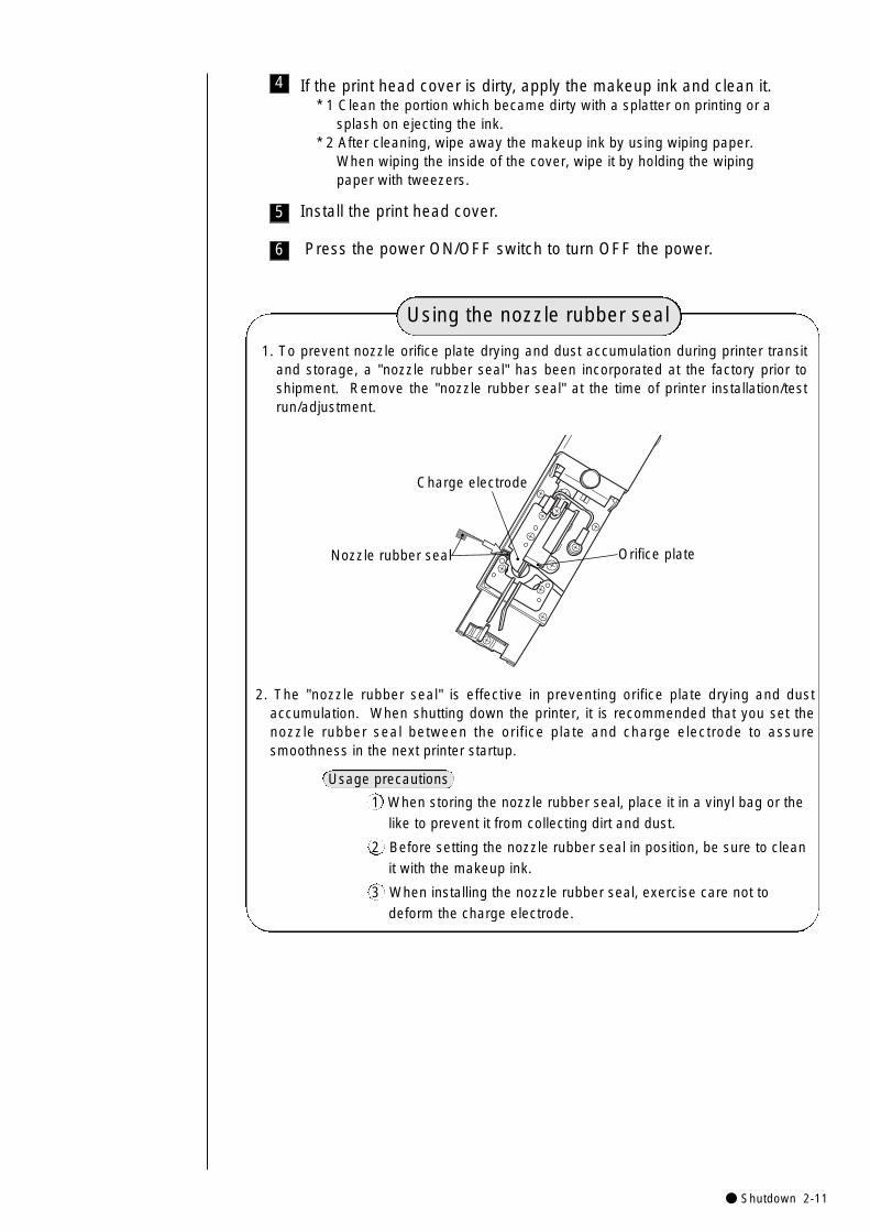
● Shutdown 2-11
5 Install the print head cover.
6 Press the power ON/OFF switch to turn OFF the power.
4 If the print head cover is dirty, apply the makeup ink and clean it.* 1 Clean the portion which became dirty with a splatter on printing or a
splash on ejecting the ink.* 2 After cleaning, wipe away the makeup ink by using wiping paper.
When wiping the inside of the cover, wipe it by holding the wiping paper with tweezers.
2. The "nozzle rubber seal" is effective in preventing orifice plate drying and dustaccumulation. When shutting down the printer, it is recommended that you set thenozzle rubber seal between the orifice plate and charge electrode to assuresmoothness in the next printer startup.
Usage precautions
1 When storing the nozzle rubber seal, place it in a vinyl bag or the
like to prevent it from collecting dirt and dust.
2 Before setting the nozzle rubber seal in position, be sure to clean
it with the makeup ink.
3 When installing the nozzle rubber seal, exercise care not to
deform the charge electrode.
1. To prevent nozzle orifice plate drying and dust accumulation during printer transitand storage, a "nozzle rubber seal" has been incorporated at the factory prior toshipment. Remove the "nozzle rubber seal" at the time of printer installation/testrun/adjustment.
Charge electrode
Orifice plateNozzle rubber seal
Using the nozzle rubber seal
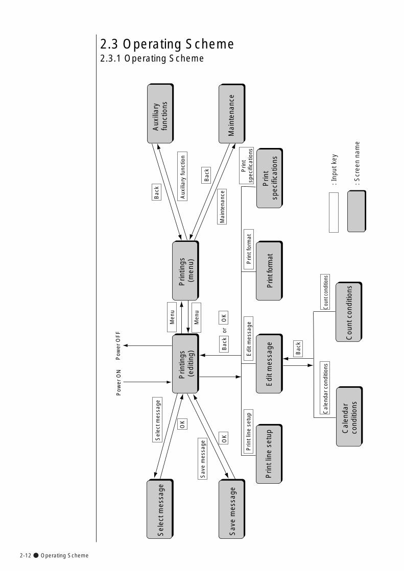
2-12● Operating Scheme
2.3 Operating Scheme
Sav
e m
essa
ge
Cal
enda
r c
ondi
tions
YE
SP
rintin
gs (
editi
ng)
Prin
tings
(m
enu)
Aux
iliar
y fu
nctio
ns
Edi
t mes
sage
Prin
t for
mat
Prin
t sp
ecifi
catio
ns
Men
u
Pow
er O
N P
ower
OF
F
Prin
t lin
e se
tup
Sel
ect m
essa
ge S
elec
t mes
sage
Sav
e m
essa
ge
Prin
t lin
e se
tup
Cou
nt c
ondi
tions
Cal
enda
r co
nditi
ons
Coun
t con
ditio
ns
Bac
k
Edi
t mes
sage
Prin
t for
mat
Prin
t sp
ecifi
catio
ns
Bac
kM
aint
enan
ce
Aux
iliar
y fu
nctio
n
Mai
nten
ance
Bac
k
Men
u
OK
OK
orO
K
Bac
k
: Inp
ut k
ey
: Scr
een
nam
e
2.3.1 Operating Scheme

● Operating Scheme 2-13
(2)The current status including the on-line/off-line (communication) state
is constantly displayed at the top of the screen.
2.3.2 Status(1) The printer is in one of the following states.
No. State Description
1 Stop The ink is stopped. No deflection voltage is applied.
2 Standby The ink is ejected. No deflection voltage is applied.
3 Ready The ink is ejected. The deflection voltage is applied (printing ispermitted by the sensor signal).
5
Starting State in which the printer changes from the inactive state tothe standby state.
6
Ink heating Start up in process, with the ink being heated.
7
Drop adjust Period during which ink particles are not properly charged in the standby state.
8
Cover open Period during which the nozzle head cover is open in thestandby state.
9
Service Circulation control process for maintenance task execution.
Fault State in which a fault exists.
Status: Stop Com=0
Manual
Startup
Shutdown
CommOn/Off
Status: Stop Com=0�Warning : Ink Low Warning
Manual
Startup
Shutdown
CommOn/Off
(3)When a warning condition occurs, its description appears on the screen.
4
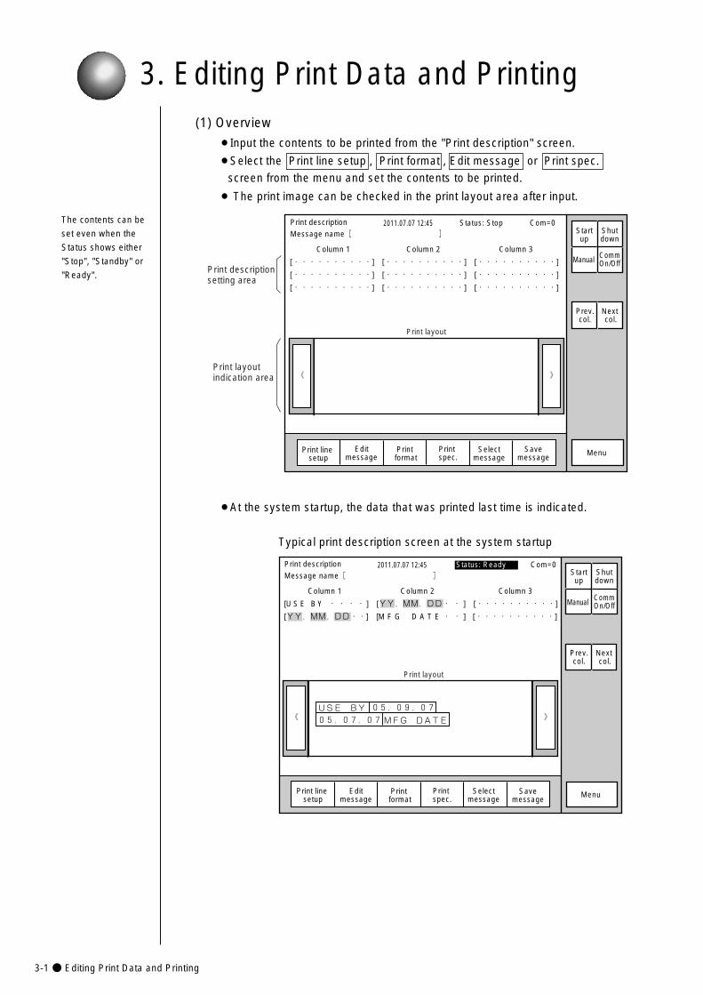
3-1● Editing Print Data and Printing
3. Editing Print Data and Printing(1) Overview
¡Input the contents to be printed from the "Print description" screen.
¡Select the Print line setup , Print format , Edit message or Print spec.
screen from the menu and set the contents to be printed.
¡ The print image can be checked in the print layout area after input.
The contents can be
set even when the
Status shows either
"Stop", "Standby" or
"Ready".
》《
Column 1 Column 2 Column 3
[・・・・・・・・・・] [・・・・・・・・・・] [・・・・・・・・・・]
[・・・・・・・・・・] [・・・・・・・・・・] [・・・・・・・・・・]
[・・・・・・・・・・] [・・・・・・・・・・] [・・・・・・・・・・]
Print description 2011.07.07 12:45
Selectmessage
Message name[ ] Startup
Shutdown
Manual
MenuPrint line setup
Editmessage
Print format
Print spec.
CommOn/Off
Print layout
Status: Stop Com=0
Prev.col.
Next col.
Print descriptionsetting area
Print layoutindication area
Savemessage
¡At the system startup, the data that was printed last time is indicated.
Typical print description screen at the system startup
》《USE BY
MFG DATE�05.07.07�
05.09.07�
Column 1 Column 2 Column 3
[U S E B Y ・・・・ ] [YY.MM.DD・・ ] [・・・・・・・・・・]
[YY.MM.DD・・] [M F G D A T E・・ ] [・・・・・・・・・・]
Print description 2011.07.07 12:45Message name[ ]
Manual
MenuPrint format
Print spec.
Status: Ready Com=0
Prev.col.
Next col.
Print layout
Selectmessage
Startup
Shutdown
Print line setup
Editmessage
CommOn/Off
Savemessage
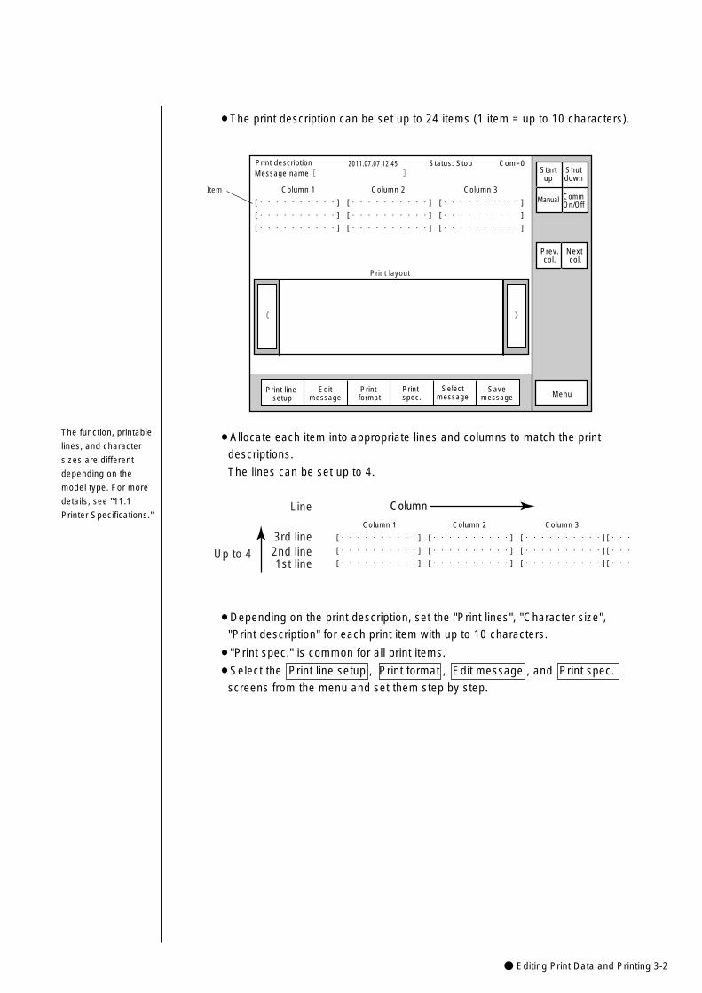
● Editing Print Data and Printing 3-2
¡The print description can be set up to 24 items (1 item = up to 10 characters).
》《
Column 1 Column 2 Column 3
[・・・・・・・・・・] [・・・・・・・・・・] [・・・・・・・・・・]
[・・・・・・・・・・] [・・・・・・・・・・] [・・・・・・・・・・]
[・・・・・・・・・・] [・・・・・・・・・・] [・・・・・・・・・・]
Print description 2011.07.07 12:45
Manual
Print layout
Status: Stop Com=0
Prev.col.
Next col.
Item
Menu
Message name[ ] Startup
Shutdown
CommOn/Off
Selectmessage
Print line setup
Editmessage
Print format
Print spec.
Savemessage
¡Allocate each item into appropriate lines and columns to match the print
descriptions.
The lines can be set up to 4.
Column 1 Column 2 Column 3
[・・・・・・・・・・] [・・・・・・・・・・] [・・・・・・・・・・] [・・・
[・・・・・・・・・・] [・・・・・・・・・・] [・・・・・・・・・・] [・・・
[・・・・・・・・・・] [・・・・・・・・・・] [・・・・・・・・・・] [・・・�
Column
Up to 4
Line
3rd line2nd line1st line
¡Depending on the print description, set the "Print lines", "Character size",
"Print description" for each print item with up to 10 characters.
¡"Print spec." is common for all print items.
¡Select the Print line setup , Print format , Edit message , and Print spec.
screens from the menu and set them step by step.
The function, printable
lines, and character
sizes are different
depending on the
model type. For more
details, see "11.1
Printer Specifications."
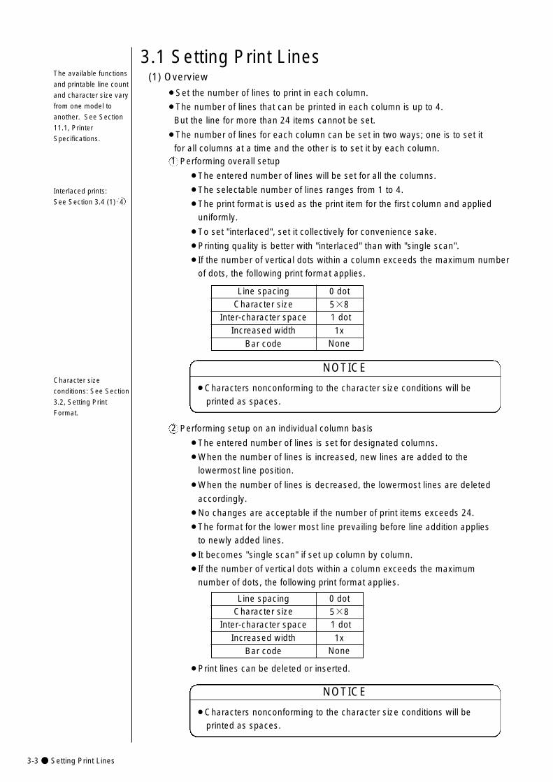
3-3● Setting Print Lines
Performing overall setup
¡The entered number of lines will be set for all the columns.
¡The selectable number of lines ranges from 1 to 4.
¡The print format is used as the print item for the first column and applied
uniformly.
¡To set "interlaced", set it collectively for convenience sake.
¡Printing quality is better with "interlaced" than with "single scan".
¡If the number of vertical dots within a column exceeds the maximum number
of dots, the following print format applies.
1
Line spacingCharacter size
Increased widthInter-character space
0 dot5×81 dot
1xBar code None
Character size
conditions: See Section
3.2, Setting Print
Format.
¡Characters nonconforming to the character size conditions will be
printed as spaces.
NOTICE
(1) Overview
¡Set the number of lines to print in each column.
¡The number of lines that can be printed in each column is up to 4.
But the line for more than 24 items cannot be set.
¡The number of lines for each column can be set in two ways; one is to set it
for all columns at a time and the other is to set it by each column.
3.1 Setting Print Lines
Performing setup on an individual column basis
¡The entered number of lines is set for designated columns.
¡When the number of lines is increased, new lines are added to the
lowermost line position.
¡When the number of lines is decreased, the lowermost lines are deleted
accordingly.
¡No changes are acceptable if the number of print items exceeds 24.
¡The format for the lower most line prevailing before line addition applies
to newly added lines.
¡It becomes "single scan" if set up column by column.
¡If the number of vertical dots within a column exceeds the maximum
number of dots, the following print format applies.
2
¡Characters nonconforming to the character size conditions will be
printed as spaces.
NOTICE
The available functions
and printable line count
and character size vary
from one model to
another. See Section
11.1, Printer
Specifications.
Line spacingCharacter size
Increased widthInter-character space
0 dot5×81 dot
1xBar code None
Interlaced prints:
See Section 3.4 (1) 4
¡Print lines can be deleted or inserted.
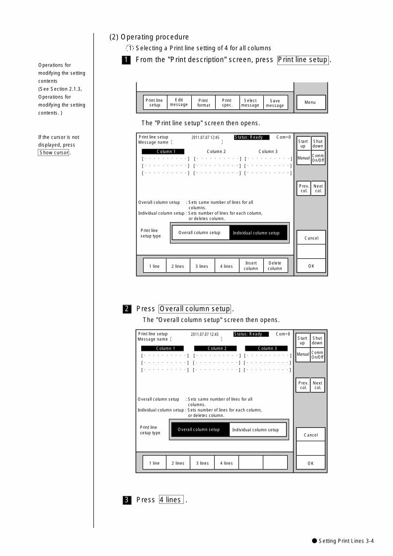
● Setting Print Lines 3-4
3
2
1
The "Print line setup" screen then opens.
Print linesetup type
Print line setup 2011.07.07 12:45
Manual
OK1 line 2 lines 3 lines 4 linesInsert
columnDeletecolumn
Individual column setupOverall column setupCancel
Overall column setup : Sets same number of lines for all columns.Individual column setup : Sets number of lines for each column, or deletes column.
Column 1 Column 2 Column 3
[・・・・・・・・・・] [・・・・・・・・・・] [・・・・・・・・・・]
[・・・・・・・・・・] [・・・・・・・・・・] [・・・・・・・・・・]
[・・・・・・・・・・] [・・・・・・・・・・] [・・・・・・・・・・]
Status: Ready Com=0
Prev.col.
Next col.
Message name[ ] Startup
Shutdown
CommOn/Off
(2) Operating procedure
1 Selecting a Print line setting of 4 for all columns
From the "Print description" screen, press Print line setup .
MenuSelectmessage
Print line setup
Editmessage
Print format
Print spec.
Savemessage
Press Overall column setup .
The "Overall column setup" screen then opens.
Print linesetup type
Print line setup 2011.07.07 12:45
Manual
OK1 line 2 lines 3 lines 4 lines
Individual column setupOverall column setupCancel
Overall column setup : Sets same number of lines for all columns.Individual column setup : Sets number of lines for each column, or deletes column.
Column 1 Column 2 Column 3
[・・・・・・・・・・] [・・・・・・・・・・] [・・・・・・・・・・]
[・・・・・・・・・・] [・・・・・・・・・・] [・・・・・・・・・・]
[・・・・・・・・・・] [・・・・・・・・・・] [・・・・・・・・・・]
Status: Ready Com=0
Prev.col.
Next col.
Message name[ ] Startup
Shutdown
CommOn/Off
Press 4 lines .
Operations for
modifying the setting
contents
(See Section 2.1.3,
Operations for
modifying the setting
contents. )
If the cursor is not
displayed, press
Show cursor .
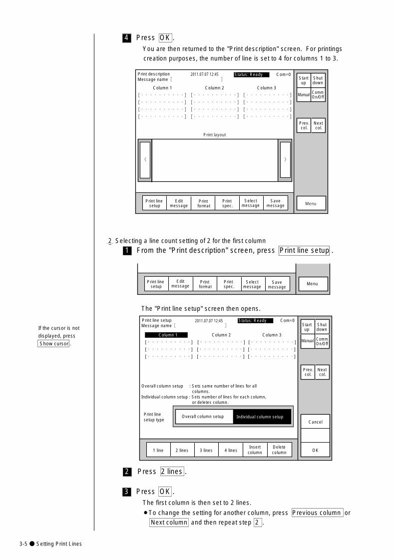
3-5● Setting Print Lines
3
2
1
4 Press OK .
You are then returned to the "Print description" screen. For printings
creation purposes, the number of line is set to 4 for columns 1 to 3.
》�《�
Column 1 Column 2 Column 3�
[・・・・・・・・・・] [・・・・・・・・・・] [・・・・・・・・・・]�
[・・・・・・・・・・] [・・・・・・・・・・] [・・・・・・・・・・] �
[・・・・・・・・・・] [・・・・・・・・・・] [・・・・・・・・・・] �
[・・・・・・・・・・] [・・・・・・・・・・] [・・・・・・・・・・]
2011.07.07 12:45
Manual
Menu
Status: Ready Com=0
Prev.col.
Next col.
Selectmessage
Message name[ ] Startup
Shutdown
Print line setup
Editmessage
Print format
Print spec.
CommOn/Off
Savemessage
Print layout
Print description
2 Selecting a line count setting of 2 for the first column
From the "Print description" screen, press Print line setup .
MenuSelectmessage
Print line setup
Editmessage
Print format
Print spec.
Savemessage
The "Print line setup" screen then opens.
Press 2 lines .
Print linesetup type
Print line setup 2011.07.07 12:45
Manual
OK1 line 2 lines 3 lines 4 lines
Individual column setupOverall column setupCancel
Insertcolumn
Deletecolumn
Overall column setup : Sets same number of lines for all columns.Individual column setup : Sets number of lines for each column, or deletes column.
Column 1 Column 2 Column 3
[・・・・・・・・・・] [・・・・・・・・・・] [・・・・・・・・・・]
[・・・・・・・・・・] [・・・・・・・・・・] [・・・・・・・・・・]
[・・・・・・・・・・] [・・・・・・・・・・] [・・・・・・・・・・]
Status: Ready Com=0
Prev.col.
Next col.
Message name[ ] Startup
Shutdown
CommOn/Off
Press OK .
The first column is then set to 2 lines.
¡To change the setting for another column, press Previous column or
Next column and then repeat step 2 .
If the cursor is not
displayed, press
Show cursor .
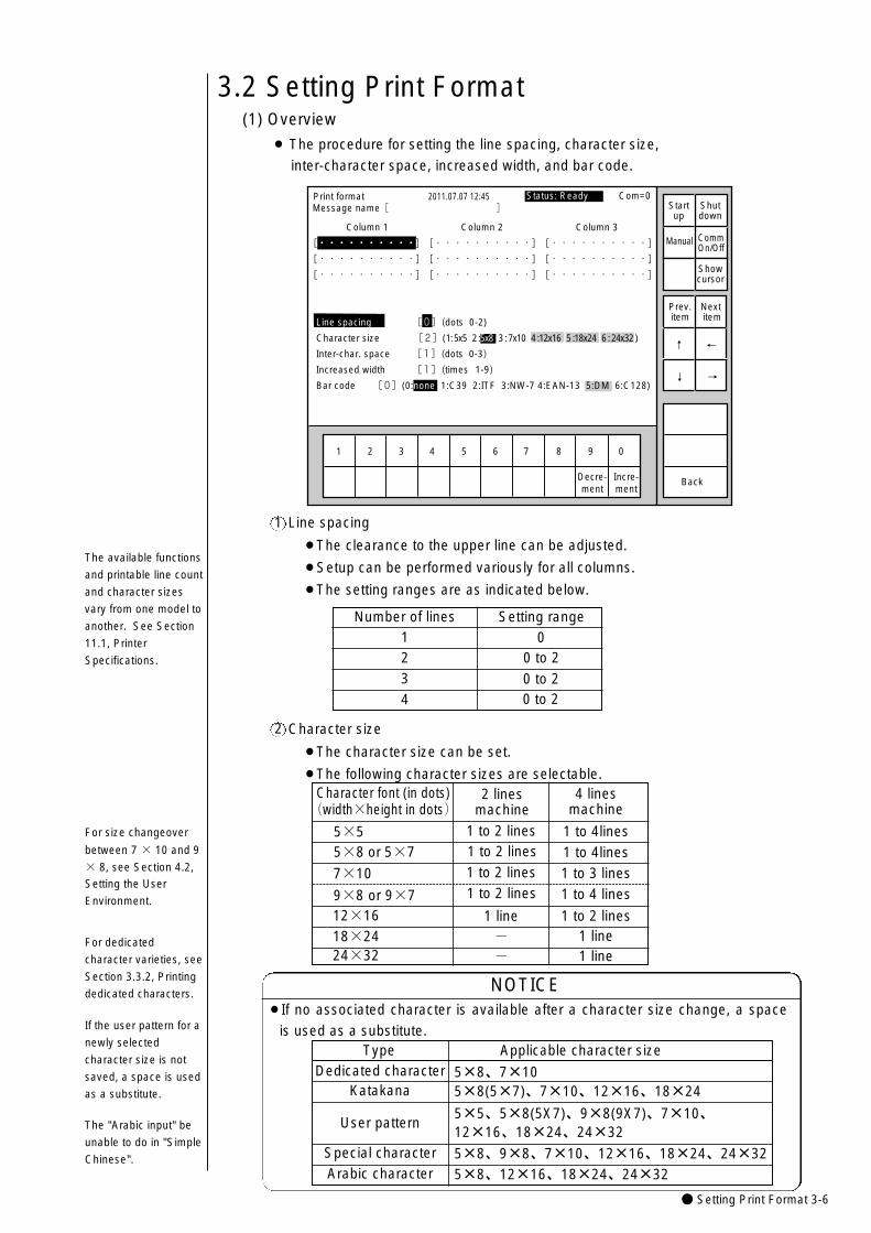
● Setting Print Format 3-6
1 to 2 lines
Character font (in dots)(width×height in dots)
5×55×8 or 5×7
7×10
9×8 or 9×712×16
24×3218×24
4 linesmachine
2 linesmachine
1 line1 line
--
1 line
1 to 2 lines
1 to 2 lines
1 to 4 lines1 to 3 lines1 to 4lines1 to 4lines
1 to 2 lines1 to 2 lines
3.2 Setting Print Format
For dedicated
character varieties, see
Section 3.3.2, Printing
dedicated characters.
Number of lines1
32
Setting range0
0 to 2
0 to 2
(1) Overview
¡ The procedure for setting the line spacing, character size,
inter-character space, increased width, and bar code.
1 2 3 4 5 6 7 8 9 0
Incre-ment
Decre-ment
Print format 2011.07.07 12:45
Back
Column 1 Column 2 Column 3
[・・・・・・・・・・] [・・・・・・・・・・] [・・・・・・・・・・] �
[・・・・・・・・・・] [・・・・・・・・・・] [・・・・・・・・・・] �
[・・・・・・・・・・] [・・・・・・・・・・] [・・・・・・・・・・]
Manual
Showcursor
Prev.item
Next item
↓
↑
Status: Ready Com=0 Message name[ ] Start
upShutdown
CommOn/Off
Line spacing [0](dots 0-2)
Character size [2](1: 5x5 2 :5x8 3 : 7x10 4 :12x16 5 :18x24 6 : 24x32 )
Inter-char. space [1](dots 0-3)
Increased width [1](times 1-9)
Bar code [0](0:none 1:C39 2:ITF 3:NW-7 4:EAN-13 5:DM 6:C128) →
←
4 0 to 2
Line spacing
¡The clearance to the upper line can be adjusted.
¡Setup can be performed variously for all columns.
¡The setting ranges are as indicated below.
Character size
¡The character size can be set.
¡The following character sizes are selectable.
TypeDedicated character
Applicable character size
5×8、7×10Katakana 5×8(5×7)、7×10、12×16、18×24
User pattern5×5、5×8(5X7)、9×8(9X7)、7×10、12×16、18×24、24×32
¡If no associated character is available after a character size change, a space
is used as a substitute.
NOTICE
If the user pattern for a
newly selected
character size is not
saved, a space is used
as a substitute.
2
1
For size changeover
between 7 × 10 and 9
× 8, see Section 4.2,
Setting the User
Environment.
The available functions
and printable line count
and character sizes
vary from one model to
another. See Section
11.1, Printer
Specifications.
Special character 5×8、9×8、7×10、12×16、18×24、24×32Arabic character 5×8、12×16、18×24、24×32
The "Arabic input" be
unable to do in "Simple
Chinese".
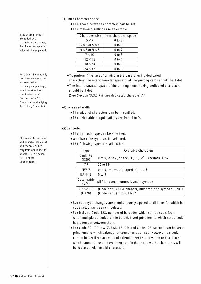
3-7● Setting Print Format
Character size5×5
9×8 or 9×75×8 or 5×7
Inter-character space0 to 30 to 3
0 to 77×10 0 to 3
12×16
24×3218×24
0 to 40 to 6
0 to 8
Inter-character space
¡The space between characters can be set.
¡The following settings are selectable.
3
Increased width
¡The width of characters can be magnified.
¡The selectable magnifications are from 1 to 9.
4
Bar code
¡The bar code type can be specified.
¡One bar code type can be selected.
¡The following types are selectable.
5
If the setting range is
exceeded by a
character size change,
the closest acceptable
value will be employed.
The available functions
and printable line count
and character sizes
vary from one model to
another. See Section
11.1, Printer
Specifications.
¡Bar code type changes are simultaneously applied to all items for which bar
code setup has been cimpeleted.
¡For DM and Code 128, number of barcodes which can be set is four.
When multiple barcodes are to be set, insert print item to which no barcode
has been set between them.
¡For Code 39, ITF, NW-7, EAN-13, DM and Code 128 barcode can be set to
print items to which calendar or count has been set. However, barcode
cannot be set if replacement of calendar, zero suppression or characters
which cannot be used have been set. In these cases, the characters will
be replaced with invalid characters.
¡To perform "interlaced" printing in the case of using dedicated
characters, the inter-character space of all the printing items should be 1 dot.
¡The inter-character space of the printing items having dedicated characters
should be 1 dot.
(See Section "3.3.2 Printing dedicated characters".)
For a Inter-line method,
see "Precautions to be
observed when
changing the printings,
print format, or line
count setup data"
(See section 2.1.3,
Operation for Modifying
the Setting Contents.)
Type
Code 39(C39)
NW-7
ITF
Available characters
0 to 9, A to Z, space, +, -, /, . (period), $, %
00 to 99
0 to 9, +, -, /, .(period), :, $EAN-13
Data matrix(DM)
Code128(C128)
0 to 9
All Alphabets, numerals and symbols
(Code set B) All Alphabets, numerals and symbols, FNC1(Code set C) 0 to 9, FNC1
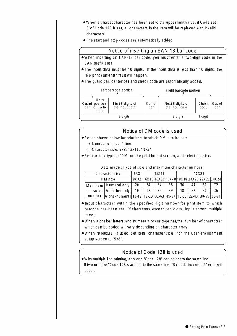
● Setting Print Format 3-8
Guardbar
Units position of Prefix
code
First 5 digits ofthe input data
Centerbar
Checkcode
Next 5 digits ofthe input data
Guardbar
Left barcode portion Right barcode portion
5 digits 5 digits 1 digit
¡When inserting an EAN-13 bar code, you must enter a two-digit code in the
EAN prefix area.
¡The input data must be 10 digits. If the input data is less than 10 digits, the
"No print contents" fault will happen.
¡The guard bar, center bar and check code are automatically added.
Notice of inserting an EAN-13 bar code
¡When alphabet character has been set to the upper limit value, if Code set
C of Code 128 is set, all characters in the item will be replaced with invalid
characters.
¡The start and stop codes are automatically added.
¡Set as shown below for print item to which DM is to be set:
(i) Number of lines: 1 line
(ii) Character size: 5x8, 12x16, 18x24
¡Set barcode type to "DM" on the print format screen, and select the size.
Data matrix: Type of size and maximum character number
¡Input characters within the specified digit number for print item to which
barcode has been set. If characters exceed ten digits, input across multiple
items.
¡When alphabet letters and numerals occur together,the number of characters
which can be coded will vary depending on character array.
¡When "DM8x32" is used, set item "character size 1"on the user environment
setup screen to "5x8".
Notice of DM code is used
¡With multiple line printing, only one "Code 128" can be set to the same line.
If two or more "Code 128"s are set to the same line, "Barcode incorrect 2" error will
occur.
Notice of Code 128 is used
5X88X32
2010
10-19
Character sizeDM size
Maximumcharacternumber
Numeral onlyAlphabet onlyAlpha-numeral
12X1616X16
2412
12-23
16X366432
32-63
16X489849
49-97
18X2418X18
3618
18-35
20X204422
22-43
22X226030
30-59
24X247236
36-71
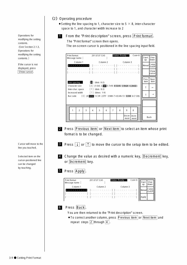
3-9● Setting Print Format
6
4
3
2
Press Back .
You are then returned to the "Print description" screen.
¡To correct another column, press Previous item or Next item and
repeat steps 2 through 4 .
Press Previous item or Next item to select an item whose print
format is to be changed.
Press ↓ or ↑ to move the cursor to the setup item to be edited.
Change the value as desired with a numeric key, Decrement key,
or Increment key.
1
1 2 3 4 5 6 7 8 9 0
Incre-ment
Decre-ment
Print format 2011.07.07 12:45
Back
Column 1 Column 2 Column 3
[・・・・・・・・・・] [・・・・・・・・・・] [・・・・・・・・・・] �
[・・・・・・・・・・] [・・・・・・・・・・] [・・・・・・・・・・] �
[・・・・・・・・・・] [・・・・・・・・・・] [・・・・・・・・・・]
Manual
Showcursor
Prev.item
Next item
↓
↑
Status: Ready Com=0 Message name[ ] Start
upShutdown
CommOn/Off
Line spacing [0](dots 0-2)
Character size [2](1: 5x5 2 :5x8 3 : 7x10 4 :12x16 5 :18x24 6 : 24x32 )
Inter-char. space [1](dots 0-3)
Increased width [1](times 1-9)
Bar code [0](0:none 1:C39 2:ITF 3:NW-7 4:EAN-13 5:DM 6:C128) →
←
From the "Print description" screen, press Print format .
The "Print format" screen then opens.
The on-screen cursor is positioned in the line spacing input field.
(2)Operating procedure¡Setting the line spacing to 1, character size to 5 × 8, inter-character
space to 1, and character width increase to 2
5 Press Apply .
Operations for
modifying the setting
contents.
(See Section 2.1.3,
Operations for
modifying the setting
contents.)
If the cursor is not
displayed, press
Show cursor .
Print format 2011.07.07 12:45
Column 1 Column 2 Column 3
[・・・・・・・・・・] [・・・・・・・・・・] [・・・・・・・・・・] �
[・・・・・・・・・・] [・・・・・・・・・・] [・・・・・・・・・・] �
[・・・・・・・・・・] [・・・・・・・・・・] [・・・・・・・・・・]
Manual
Apply
Status: Ready Com=0 Message name[ ] Start
upShutdown
CommOn/Off
Cursor will move to the
line you touched.
Selected item on the
cursor-positioned line
can be changed
by touching.
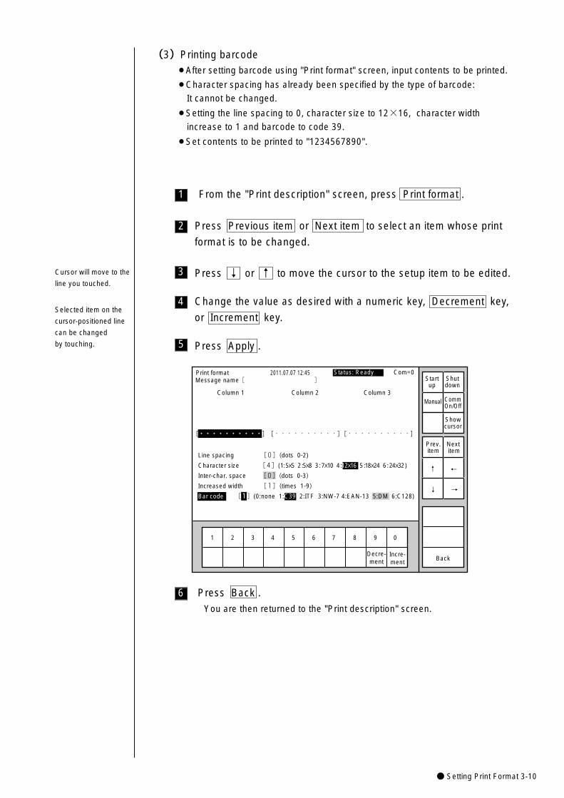
● Setting Print Format 3-10
1
1 2 3 4 5 6 7 8 9 0
Incre-ment
Decre-ment
Print format 2011.07.07 12:45
Back
Column 1 Column 2 Column 3
�
�
�
[・・・・・・・・・・] [・・・・・・・・・・] [・・・・・・・・・・] �
Line spacing [0](dots 0-2)
Character size [4](1: 5x5 2 :5x8 3 : 7x10 4 :12x16 5 :18x24 6 : 24x32 )
Inter-char. space [0](dots 0-3)
Increased width [1](times 1-9)
Bar code [1](0:none 1:C39 2:ITF 3:NW-7 4:EAN-13 5:DM 6:C128)
Manual
Showcursor
Prev.item
Next item
↓
↑
Status: Ready Com=0Message name[ ] Start
upShutdown
CommOn/Off
→
←
From the "Print description" screen, press Print format .
(3)Printing barcode¡After setting barcode using "Print format" screen, input contents to be printed.
¡Character spacing has already been specified by the type of barcode:
It cannot be changed.
¡Setting the line spacing to 0, character size to 12×16, character width
increase to 1 and barcode to code 39.
¡Set contents to be printed to "1234567890".
3
2 Press Previous item or Next item to select an item whose print
format is to be changed.
Press ↓ or ↑ to move the cursor to the setup item to be edited.
4 Change the value as desired with a numeric key, Decrement key,
or Increment key.
5 Press Apply .
6 Press Back .
You are then returned to the "Print description" screen.
Cursor will move to the
line you touched.
Selected item on the
cursor-positioned line
can be changed
by touching.

3-11● Setting Print Format
7 From the "Print description" screen, press Edit message .
The "Edit message" screen then opens. Keyboard for inputting Code 39
will be displayed.
Insert Delete
K
U
A
L
V
B
M
W
C
N
X
D
O
Y
E
P
Z
F
Q
+
G
R
-
H
S
I
T
/
J
Space BlankBack-space$ %
Edit message
Column 1 Column 2 Column 3
[・・・・・・・・・・] [・・・・・・・・・・] [・・・・・・・・・・]
2011.07.07 12:45
Back
Calendar conditions
Count conditions
1 2 3 4 5 6 7 8 9 0
ABC・123・�
Manual
Showcursor
Prev.col.
Next col.
↓
↑
→
←
Status: Ready Com=0 Message name[ ] Start
upShutdown
CommOn/Off
.
8 Press 1 2 3 4 5 6 7 8 9 0 .
9 Press Apply .
10 Press Back .
You are then returned to the "Print description" screen.
¡Input numeric characters will be displayed in red on print layout screen.
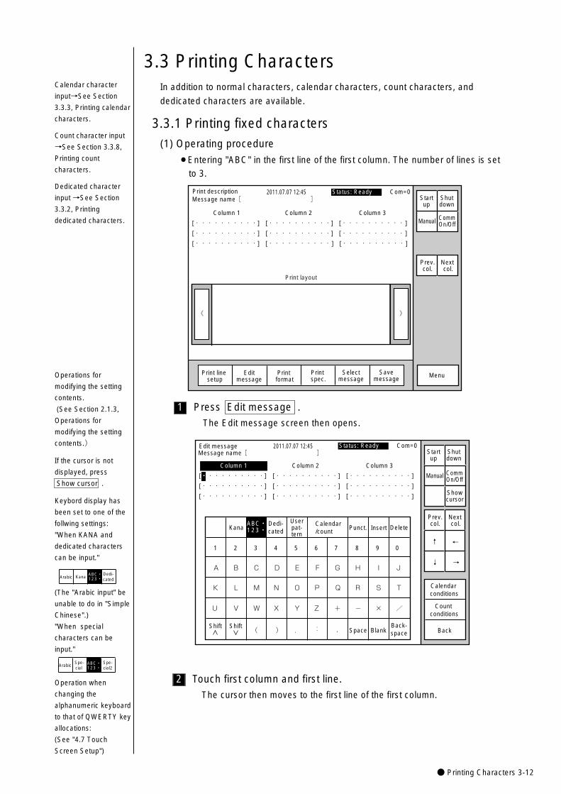
● Printing Characters 3-12
3.3 Printing CharactersIn addition to normal characters, calendar characters, count characters, and
dedicated characters are available.
(1) Operating procedure
¡Entering "ABC" in the first line of the first column. The number of lines is set
to 3.
3.3.1 Printing fixed characters
》《
Column 1 Column 2 Column 3
[・・・・・・・・・・] [・・・・・・・・・・] [・・・・・・・・・・ ]
[・・・・・・・・・・] [・・・・・・・・・・] [・・・・・・・・・・ ]
[・・・・・・・・・・] [・・・・・・・・・・ ] [・・・・・・・・・・ ]
Print description 2011.07.07 12:45
Manual
Menu
Print layout
Status: Ready Com=0
Prev.col.
Next col.
Selectmessage
Message name[ ] Startup
Shutdown
Print line setup
Editmessage
Print format
Print spec.
CommOn/Off
Savemessage
Calendar character
input→See Section
3.3.3, Printing calendar
characters.
Count character input
→See Section 3.3.8,
Printing count
characters.
Dedicated character
input →See Section
3.3.2, Printing
dedicated characters.
2
1
KanaDedi-cated
Userpat-tern
Calendar/count
Punct. Insert Delete
K
U
A
Shift
L
V
B
M
W
C
N
X
D
O
Y
E
P
Z
F
Q
+
G
R
-
H
S
×
I
T
/
J
Space BlankBack-space( ) . : ,
Edit message
Column 1 Column 2 Column 3
[・・・・・・・・・・] [・・・・・・・・・・] [・・・・・・・・・・]
[・・・・・・・・・・] [・・・・・・・・・・] [・・・・・・・・・・]
[・・・・・・・・・・] [・・・・・・・・・・] [・・・・・・・・・・]
2011.07.07 12:45
Back
Calendar conditions
Count conditions
1 2 3 4 5 6 7 8 9 0
ABC・123・�
Manual
Showcursor
Prev.col.
Next col.
↓
↑
→
←
Status: Ready Com=0 Message name[ ] Start
upShutdown
CommOn/Off
Shift
Touch first column and first line.
The cursor then moves to the first line of the first column.
Press Edit message .
The Edit message screen then opens.
Operations for
modifying the setting
contents.
(See Section 2.1.3,
Operations for
modifying the setting
contents.)
If the cursor is not
displayed, press
Show cursor .
Operation when
changing the
alphanumeric keyboard
to that of QWERTY key
allocations:
(See "4.7 Touch
Screen Setup")
Keybord display has
been set to one of the
follwing settings:
"When KANA and
dedicated characters
can be input."
KanaDedi-cated
ABC・123・�Arabic
(The "Arabic input" be
unable to do in "Simple
Chinese".)
"When special
characters can be
input."
Spe-cial
Spe-cial2
ABC・123・�Arabic
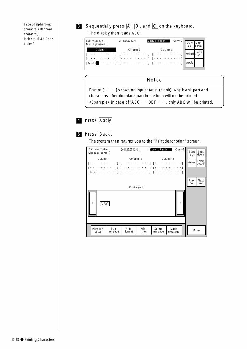
3-13● Printing Characters
5
3
Edit message
Column 1 Column 2 Column 3
[・・・・・・・・・・] [・・・・・・・・・・] [・・・・・・・・・・] �
[・・・・・・・・・・] [・・・・・・・・・・] [・・・・・・・・・・] �
[ABC・・・・・・・] [・・・・・・・・・・] [・・・・・・・・・・] �
2011.07.07 12:45
Manual
Apply
Status: Ready Com=0Message name[ ] Start
upShutdown
CommOn/Off
Sequentially press A , B , and C on the keyboard.
The display then reads ABC.
Press Back .
The system then returns you to the "Print description" screen.
ABC� 》《
Column 1 Column 2 Column 3
[・・・・・・・・・・] [・・・・・・・・・・] [・・・・・・・・・・] �
[・・・・・・・・・・] [・・・・・・・・・・] [・・・・・・・・・・]
[ABC・・・・・・・] [・・・・・・・・・・] [・・・・・・・・・・] �
Print description 2011.07.07 12:45
Manual
Menu
Status: Ready Com=0
Prev.col.
Next col.
Selectmessage
Message name[ ] Startup
Shutdown
Print line setup
Editmessage
Print format
Print spec.
CommOn/Off
Print layout
Savemessage
4 Press Apply .
Type of alphameric
character (standard
character):
Refer to "6.4.6 Code
tables".
Notice
Part of [・・・] shows no input status (blank): Any blank part and
characters after the blank part in the item will not be printed.
<Example> In case of "ABC・・DEF・・", only ABC will be printed.
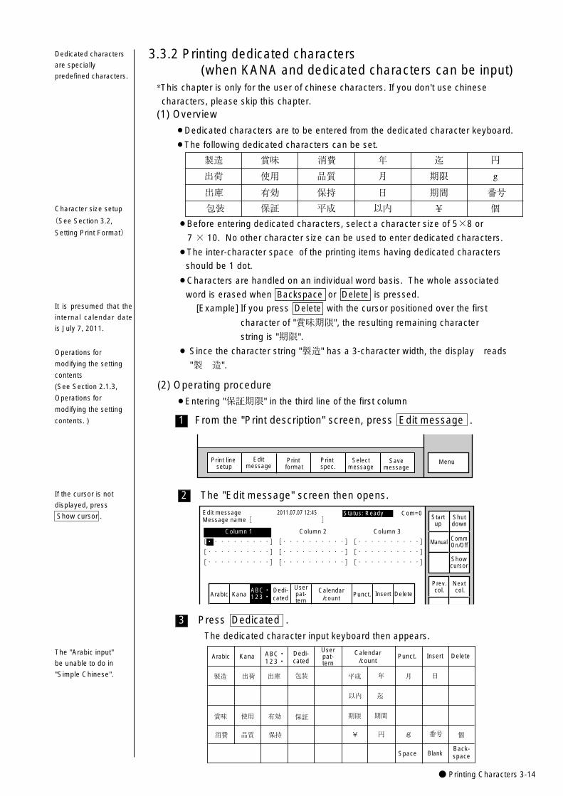
● Printing Characters 3-14
3
2
1
(1) Overview
¡Dedicated characters are to be entered from the dedicated character keyboard.
¡The following dedicated characters can be set.
3.3.2 Printing dedicated characters (when KANA and dedicated characters can be input)
製造
出荷
出庫
包装
賞味
使用
有効
保証
消費
品質
保持
平成
年
月
日
以内
迄
期限
期間
¥
円
g
番号
個
Dedicated characters
are specially
predefined characters.
Character size setup
(See Section 3.2,
Setting Print Format)
(2) Operating procedure
¡Entering "保証期限" in the third line of the first column
From the "Print description" screen, press Edit message .
The "Edit message" screen then opens.
MenuSelectmessage
Print line setup
Editmessage
Print format
Print spec.
Savemessage
KanaArabicDedi-cated
Userpat-tern
Calendar/count
Punct. Insert Delete
Edit message
Column 1 Column 2 Column 3
[・・・・・・・・・・] [・・・・・・・・・・] [・・・・・・・・・・] �
[・・・・・・・・・・] [・・・・・・・・・・] [・・・・・・・・・・] �
[・・・・・・・・・・] [・・・・・・・・・・] [・・・・・・・・・・] �
2011.07.07 12:45
ABC・123・�
Status: Ready Com=0
Manual
Showcursor
Prev.col.
Next col.
Message name[ ] Startup
Shutdown
CommOn/Off
Press Dedicated .
The dedicated character input keyboard then appears.
製造�
消費�
賞味�
出荷�
使用�
出庫�
有効�
包装�
保証�
平成�
期限�
¥
以内�
年�
期間�
円�
迄�
月�
g
日�
番号� 個�品質� 保持�
Calendar/count
KanaArabic Dedi-cated
Userpat-tern
Punct. Insert Delete
Space BlankBack-space
ABC・123・�
It is presumed that the
internal calendar date
is July 7, 2011.
*This chapter is only for the user of chinese characters. If you don't use chinese
characters, please skip this chapter.
If the cursor is not
displayed, press
Show cursor .
¡Before entering dedicated characters, select a character size of 5×8 or
7 × 10. No other character size can be used to enter dedicated characters.
¡The inter-character space of the printing items having dedicated characters
should be 1 dot.
¡Characters are handled on an individual word basis. The whole associated
word is erased when Backspace or Delete is pressed.
[Example] If you press Delete with the cursor positioned over the first
character of "賞味期限", the resulting remaining character
string is "期限".
¡ Since the character string "製造" has a 3-character width, the display reads
"製 造".Operations for
modifying the setting
contents
(See Section 2.1.3,
Operations for
modifying the setting
contents. )
The "Arabic input"
be unable to do in
"Simple Chinese".
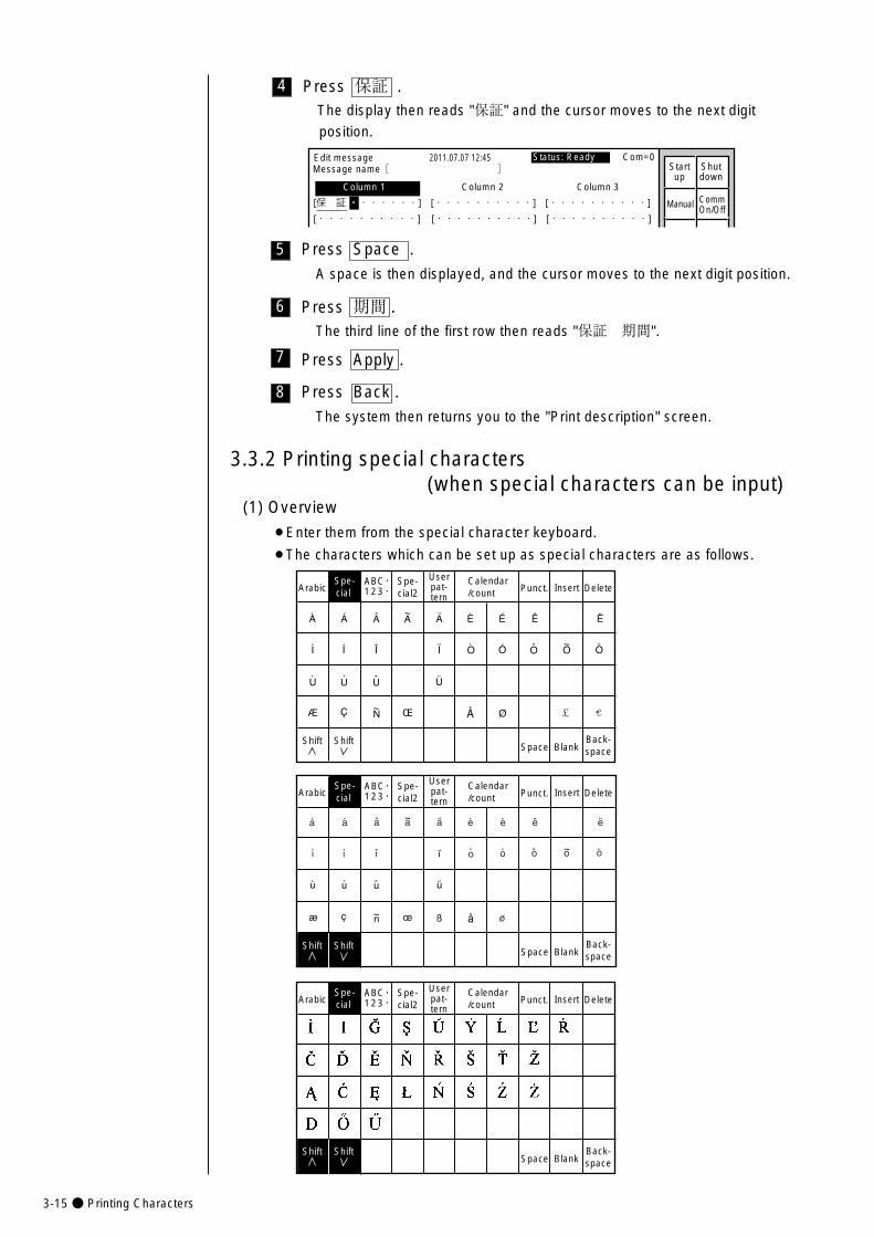
3-15● Printing Characters
8
6
5
4
Press Space .
A space is then displayed, and the cursor moves to the next digit position.
Edit message
Column 1 Column 2 Column 3
[保 証 ・・・・・・・] [・・・・・・・・・・] [・・・・・・・・・・]
[・・・・・・・・・・] [・・・・・・・・・・] [・・・・・・・・・・]
2011.07.07 12:45
Manual
Status: Ready Com=0 Message name[ ] Start
upShutdown
CommOn/Off
Press Back .
The system then returns you to the "Print description" screen.
Press 保証 .The display then reads "保証" and the cursor moves to the next digit
position.
Press 期間 .The third line of the first row then reads "保証 期間".
7 Press Apply .
(1) Overview
¡Enter them from the special character keyboard.
¡The characters which can be set up as special characters are as follows.
3.3.2 Printing special characters(when special characters can be input)
Spe-cial
Userpat-tern
Calendar/count Punct. Insert Delete
Space BlankBack-space
ABC・123・�
Spe-cial
Userpat-tern
Spe-cial2
Spe-cial2
Calendar/count Punct. Insert Delete
Space BlankBack-space
ABC・123・�
Arabic
Arabic
Spe-cial
Userpat-tern
Calendar/count Punct. Insert Delete
Space BlankBack-space
ABC・123・�
Spe-cial2Arabic
Shift Shift
Shift Shift
Shift Shift
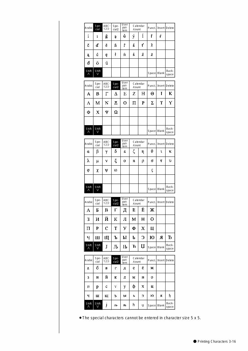
● Printing Characters 3-16
Spe-cial
Userpat-tern
Spe-cial2
Calendar/count Punct. Insert Delete
Space BlankBack-space
ABC・123・�Arabic
Spe-cial
Userpat-tern
Calendar/count Punct. Insert Delete
Space BlankBack-space
ABC・123・�
Spe-cial
Userpat-tern
Spe-cial2
Spe-cial2
Calendar/count Punct. Insert Delete
Space BlankBack-space
ABC・123・�
Arabic
Arabic
Spe-cial
Userpat-tern
Calendar/count Punct. Insert Delete
Space BlankBack-space
ABC・123・�
Spe-cial
Userpat-tern
Spe-cial2
Spe-cial2
Calendar/count Punct. Insert Delete
Space BlankBack-space
ABC・123・�
Arabic
Arabic
Shift Shift
Shift Shift
Shift Shift
Shift Shift
Shift Shift
�
¡The special characters cannot be entered in character size 5 x 5.

3-17● Printing Characters
4 Press Calendar/count .
The calendar input keyboard then appears.
Year Month Day Hour Minute
Count
Calendar/Count
KanaArabic Dedi-cated
Userpat-tern
Punct. Insert Delete
Space BlankBack-space
ABC・123・�
TotaldaysSecond
JANFEB
+� -� � /�
(� )� .� :� ,�
Weeknumber
Day ofweek
Shiftcode
Timecount
3
2
1
(1) Overview
¡The following procedure is used to set the year, month, day, hour, minute and
second.
¡ Entries are to be made from the calendar/count keyboard.
¡When entries are set up as calendar characters, the year, month, day, hour,
minute and second values will be printed in accordance with calendar time
changes.
¡Calendar characters cannot be printed in the same print item with shift code
characters or time count characters.
(2) Operating procedure
¡Making "year," "month," and "day" entries in the third line of the second column.
3.3.3 Printing calendar characters
From the "Print description" screen, press Edit message .
The "Edit message" screen then opens.
MenuSelectmessage
Print line setup
Editmessage
Print format
Print spec.
Savemessage
KanaArabicDedi-cated
Userpat-tern
Calendar/count
Punct. Insert Delete
Edit message
Column 1 Column 2 Column 3
[USE BY ・・・・] [・・・・・・・・・・] [・・・・・・・・・・]
[YY.MM.DD ・・] [M F G D A T E・・ ] [・・・・・・・・・・]
[ABC ・・・・・・・] [・・・・・・・・・・] [・・・・・・・・・・]
2011.07.07 12:45
ABC・ �123・ �
Manual
Showcursor
Prev.col.
Next col.
Status: Ready Com=0Message name[ ] Start
upShutdown
CommOn/Off
Press Next column .
The cursor then moves to the beginning of the second column.
The calendar time is
the time indicated by
the internal clock of the
IJ printer.
If the cursor is not
displayed, press
Show cursor .
Operations for
modifying the setting
contents
(See Section 2.1.3,
Operations for
modifying the setting
contents. )
Keybord display has
been set to one of the
follwing settings:
"When KANA and
dedicated characters
can be input."
KanaDedi-cated
ABC・123・�Arabic
(The "Arabic input" be
unable to do in "Simple
Chinese".)
"When special
characters can be
input."
Spe-cial
Spe-cial2
ABC・123・�Arabic
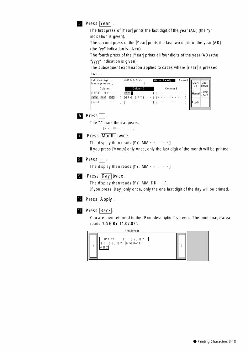
● Printing Characters 3-18
7
6
5
Press . .
The "." mark then appears.[YY.■・・・・・・]
Press Month twice.
The display then reads [YY. MM・・・・・]
If you press [Month] only once, only the last digit of the month will be printed.
Press Year .
The first press of Year prints the last digit of the year (AD) (the "y"
indication is given).
The second press of the Year prints the last two digits of the year (AD)
(the "yy" indication is given).
The fourth press of the Year prints all four digits of the year (AD) (the
"yyyy" indication is given).
The subsequent explanation applies to cases where Year is pressed
twice.
Edit message
Column 1 Column 2 Column 3
[USE BY・・・・] [YY・・・・・・・・] [・・・・・・・・・・]
[YY.MM.DD・・] [M F G D A T E・・ ] [・・・・・・・・・・]
[ABC・・・・・・・] [・・・・・・・・・・] [・・・・・・・・・・]
2011.07.07 12:45
Manual
Apply
Status: Ready Com=0 Message name[ ] Start
upShutdown
CommOn/Off
9 Press Day twice.
The display then reads [YY. MM. DD・・].
If you press Day only once, only the one last digit of the day will be printed.
8 Press . .
The display then reads [YY. MM・・・・・].
11 Press Back .
You are then returned to the "Print description" screen. The print image area
reads "USE BY 11.07.07".
》《
USE BY
11.07.07 MFG DATE11.07.07
ABC
Print layout
10 Press Apply .
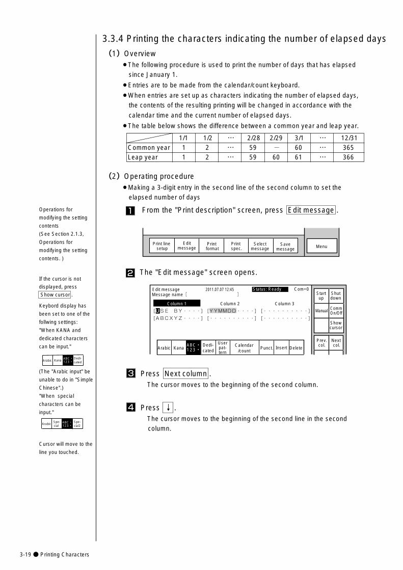
3-19● Printing Characters
Press Next column . The cursor moves to the beginning of the second column.
3
Press ↓ .The cursor moves to the beginning of the second line in the second
column.
4
The "Edit message" screen opens.
KanaArabicDedi-cated
Userpat-tern
Calendar/count
Punct. Insert Delete
Edit message
Column 1 Column 2 Column 3
[USE BY・・・・] [YYMMDD・・・・] [・・・・・・・・・・] �
[ABCXYZ・・・・] [・・・・・・・・・・] [・・・・・・・・・・] �
2011.07.07 12:45
ABC・123・�
Manual
Showcursor
Prev.col.
Next col.
Status: Ready Com=0 Message name[ ] Start
upShutdown
CommOn/Off
2If the cursor is not
displayed, press
Show cursor .
1
(1)Overview¡The following procedure is used to print the number of days that has elapsed
since January 1.
¡Entries are to be made from the calendar/count keyboard.
¡When entries are set up as characters indicating the number of elapsed days,
the contents of the resulting printing will be changed in accordance with the
calendar time and the current number of elapsed days.
¡The table below shows the difference between a common year and leap year.
3.3.4 Printing the characters indicating the number of elapsed days
(2)Operating procedure¡Making a 3-digit entry in the second line of the second column to set the
elapsed number of days
From the "Print description" screen, press Edit message .
MenuSelectmessage
Print line setup
Editmessage
Print format
Print spec.
Savemessage
1/1 1/2 … 2/28 2/29 3/1 … 12/31Common year 1 2 … 59 - 60 … 365Leap year 1 2 … 59 60 61 … 366
Operations for
modifying the setting
contents
(See Section 2.1.3,
Operations for
modifying the setting
contents. )
Cursor will move to the
line you touched.
Keybord display has
been set to one of the
follwing settings:
"When KANA and
dedicated characters
can be input."
KanaDedi-cated
ABC・123・�Arabic
(The "Arabic input" be
unable to do in "Simple
Chinese".)
"When special
characters can be
input."
Spe-cial
Spe-cial2
ABC・123・�Arabic
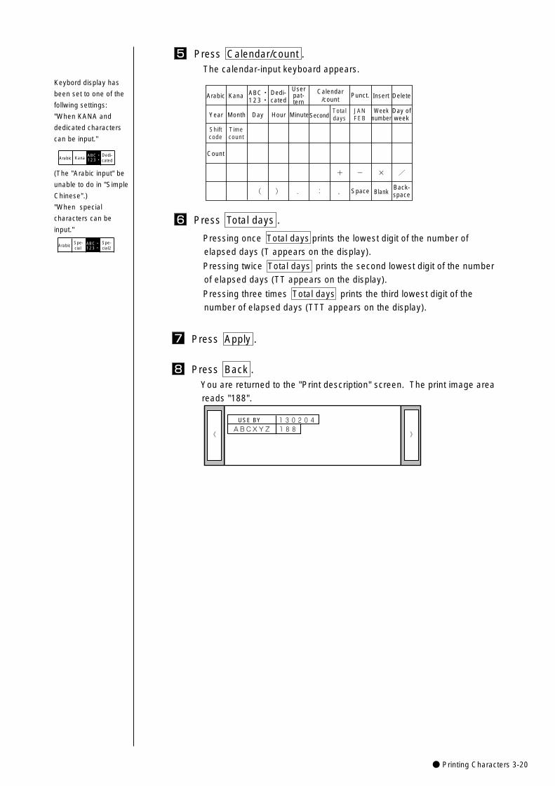
● Printing Characters 3-20
5 Press Calendar/count .The calendar-input keyboard appears.
TotaldaysYear Month Day Hour Minute
Count
Calendar/countKanaArabic Dedi-
cated
Userpat-tern
Punct. Insert Delete
Space BlankBack-space
ABC・123・�
SecondJANFEB
+� -� � /�
(� )� .� :� ,�
Weeknumber
Day ofweek
Shiftcode
Timecount
Press Total days .
Pressing once Total days prints the lowest digit of the number of
elapsed days (T appears on the display).
Pressing twice Total days prints the second lowest digit of the number
of elapsed days (TT appears on the display).
Pressing three times Total days prints the third lowest digit of the
number of elapsed days (TTT appears on the display).
6
Press Back .You are returned to the "Print description" screen. The print image area
reads "188".
8
》《
USE BY
188�130204
ABCXYZ
7 Press Apply .
Keybord display has
been set to one of the
follwing settings:
"When KANA and
dedicated characters
can be input."
KanaDedi-cated
ABC・123・�Arabic
(The "Arabic input" be
unable to do in "Simple
Chinese".)
"When special
characters can be
input."
Spe-cial
Spe-cial2
ABC・123・�Arabic
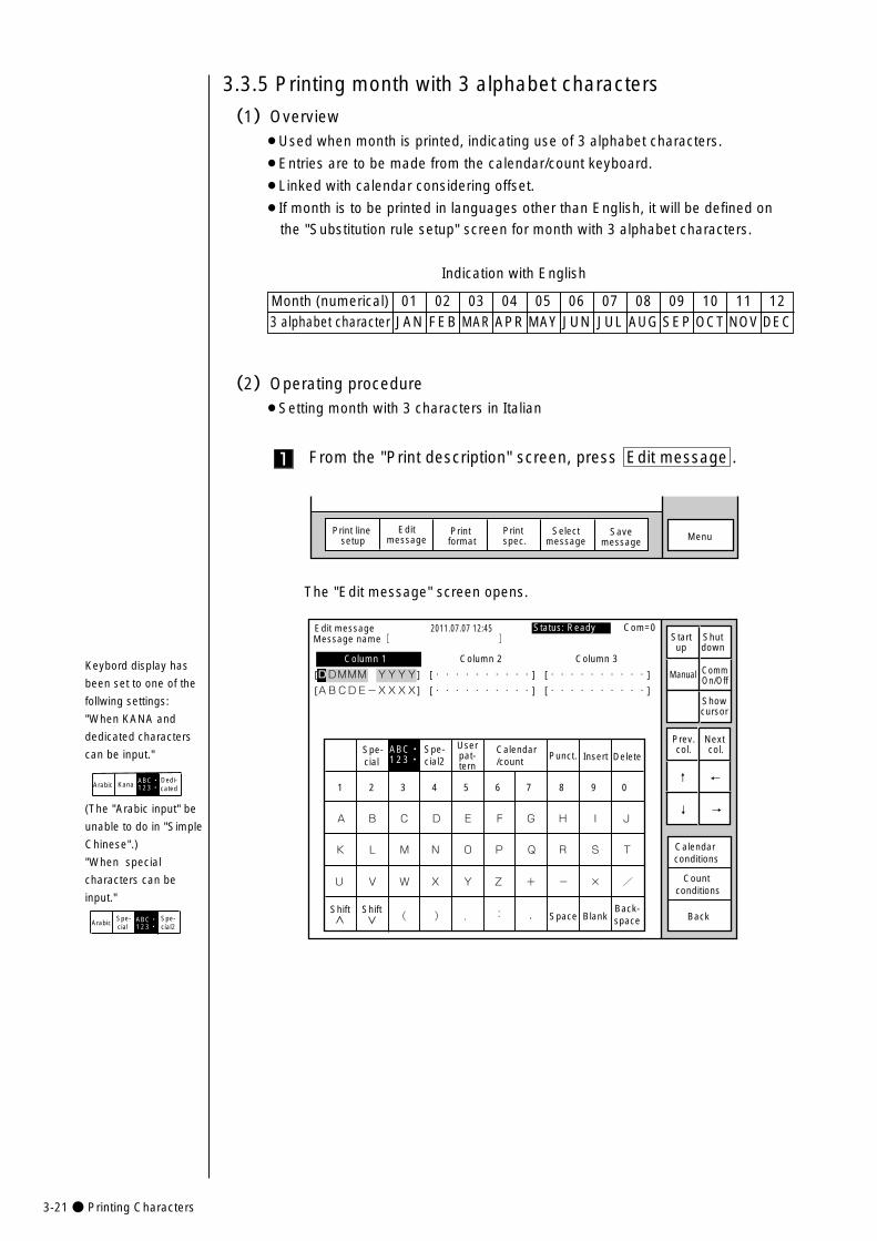
3-21● Printing Characters
The "Edit message" screen opens.
Spe-cial
Spe-cial2
Userpat-tern
Calendar/count
Punct. Insert Delete
K
U
A
Shift
L
V
B
M
W
C
N
X
D
O
Y
E
P
Z
F
Q
+
G
R
-
H
S
×
I
T
/
J
Space BlankBack-space( ) . : ,
Edit message
Column 1 Column 2 Column 3
[DDMMM・YYYY] [・・・・・・・・・・] [・・・・・・・・・・]
[ABCDE-XXXX] [・・・・・・・・・・] [・・・・・・・・・・]
2011.07.07 12:45
Back
Calendar conditions
Count conditions
1 2 3 4 5 6 7 8 9 0
ABC・123・�
Manual
Showcursor
Prev.col.
Next col.
↓
↑
→
←
Status: Ready Com=0 Message name[ ] Start
upShutdown
CommOn/Off
Shift
1
(1)Overview¡Used when month is printed, indicating use of 3 alphabet characters.
¡Entries are to be made from the calendar/count keyboard.
¡Linked with calendar considering offset.
¡If month is to be printed in languages other than English, it will be defined on
the "Substitution rule setup" screen for month with 3 alphabet characters.
Indication with English
3.3.5 Printing month with 3 alphabet characters
(2)Operating procedure¡Setting month with 3 characters in Italian
From the "Print description" screen, press Edit message .
MenuSelectmessage
Print line setup
Editmessage
Print format
Print spec.
Savemessage
01 02 03 04 05 06JAN FEB MAR APR MAY JUN
Keybord display has
been set to one of the
follwing settings:
"When KANA and
dedicated characters
can be input."
KanaDedi-cated
ABC・123・�Arabic
(The "Arabic input" be
unable to do in "Simple
Chinese".)
"When special
characters can be
input."
Spe-cial
Spe-cial2
ABC・123・�Arabic
07 08 09 10 11 12JUL AUG SEP OCT NOV DEC
Month (numerical)3 alphabet character
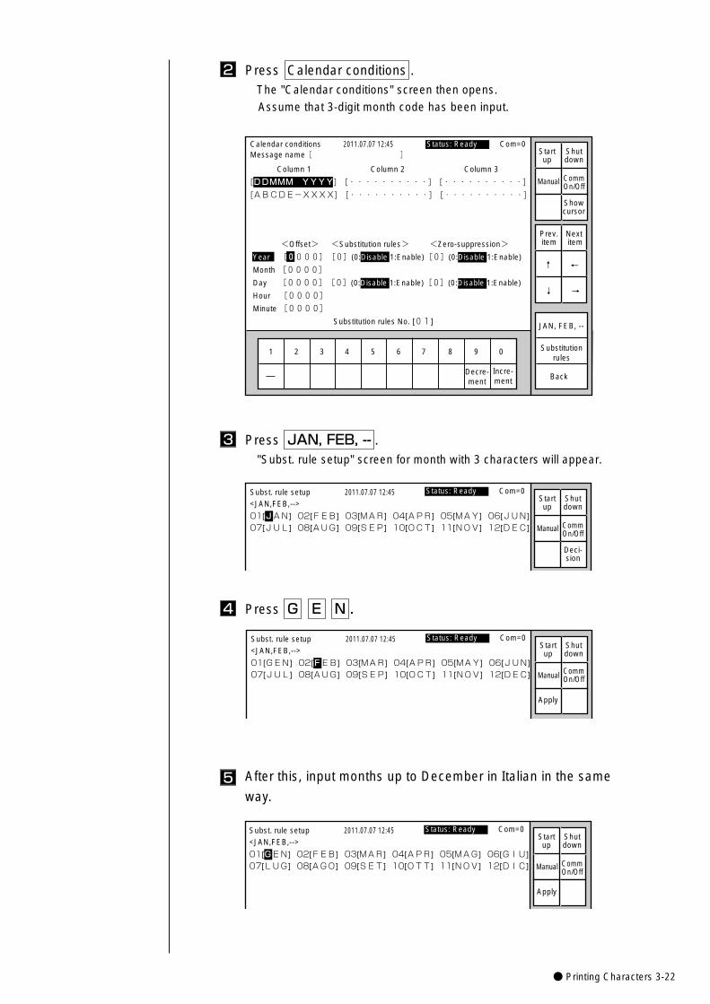
● Printing Characters 3-22
Press Calendar conditions . The "Calendar conditions" screen then opens.
Assume that 3-digit month code has been input.
2
Press JAN, FEB, -- ."Subst. rule setup" screen for month with 3 characters will appear.
3
1 2 3 4 5 6 7 8 9 0
Incre-ment
Decre-ment
Calendar conditions
Column 1 Column 2 Column 3
[DDMMM YYYY] [・・・・・・・・・・] [・・・・・・・・・・] �
[ABCDE-XXXX] [・・・・・・・・・・] [・・・・・・・・・・]
2011.07.07 12:45
Back
<Offset> <Substitution rules> <Zero-suppression>
Year [0000][0](0:Disable 1:Enable)[0](0:Disable 1:Enable)
Month [0000]�
Day [0000][0](0:Disable 1:Enable)[0](0:Disable 1:Enable)
Hour [0000]�
Minute [0000]�
Substitution rules No. [01]
Manual
Showcursor
Prev.item
Next item
↓
↑
→
←
Status: Ready Com=0
Substitutionrules
Message name[ ] Startup
Shutdown
CommOn/Off
JAN, FEB, --
01[JAN] 02[FEB] 03[MAR] 04[APR] 05[MAY] 06[JUN]
07[JUL] 08[AUG] 09[SEP] 10[OCT] 11[NOV] 12[DEC]
Subst. rule setup 2011.07.07 12:45
<JAN,FEB,-->
Manual
Deci-sion
Status: Ready Com=0 Startup
Shutdown
CommOn/Off
Press G E N . 4
01[GEN] 02[FEB] 03[MAR] 04[APR] 05[MAY] 06[JUN]
07[JUL] 08[AUG] 09[SEP] 10[OCT] 11[NOV] 12[DEC]
Subst. rule setup 2011.07.07 12:45
<JAN,FEB,-->
Manual
Apply
Status: Ready Com=0 Startup
Shutdown
CommOn/Off
After this, input months up to December in Italian in the same
way.5
01[GEN] 02[FEB] 03[MAR] 04[APR] 05[MAG] 06[GIU]
07[LUG] 08[AGO] 09[SET] 10[OTT] 11[NOV] 12[DIC]
Subst. rule setup 2011.07.07 12:45
<JAN,FEB,-->
Manual
Apply
Status: Ready Com=0 Startup
Shutdown
CommOn/Off
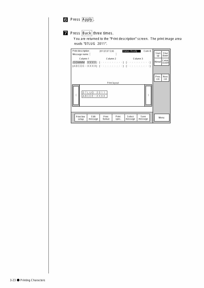
3-23● Printing Characters
6 Press Apply .
Press Back three times.You are returned to the "Print description" screen. The print image area
reads "07LUG 2011".
7
》《07LUG 2011 �ABCDE-XXXX�
Column 1 Column 2 Column 3
[DDMMM YYYY] [・・・・・・・・・・] [・・・・・・・・・・]
[ABCDE-XXXX] [・・・・・・・・・・] [・・・・・・・・・・]
Print description 2011.07.07 12:45Message name[ ]
Manual
MenuPrint format
Print spec.
Status: Ready Com=0
Prev.col.
Next col.
Print layout
Selectmessage
Startup
Shutdown
Print line setup
Editmessage
CommOn/Off
Savemessage
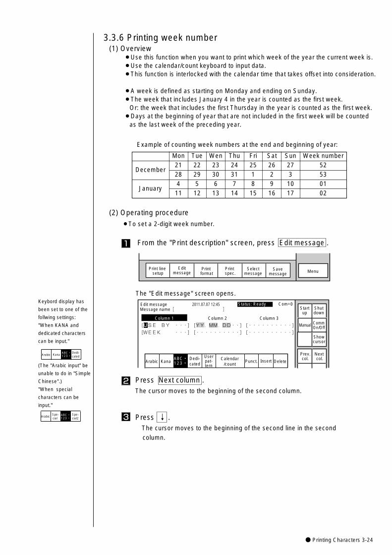
● Printing Characters 3-24
(1) Overview¡Use this function when you want to print which week of the year the current week is.¡Use the calendar/count keyboard to input data.¡This function is interlocked with the calendar time that takes offset into consideration.
¡A week is defined as starting on Monday and ending on Sunday.¡The week that includes January 4 in the year is counted as the first week.
Or: the week that includes the first Thursday in the year is counted as the first week.¡Days at the beginning of year that are not included in the first week will be counted
as the last week of the preceding year.
3.3.6 Printing week number
December
January
Mon Tue Wen Thu Fri Sat Sun Week number21 22 23 24 25 26 27 5228 29 30 31 1 2 3 534 5 6 7 8 9 10 0111 12 13 14 15 16 17 02
Example of counting week numbers at the end and beginning of year:
The "Edit message" screen opens.
KanaArabicDedi-cated
Userpat-tern
Calendar/count
Punct. Insert Delete
Edit message
Column 1 Column 2 Column 3
[USE BY ・・・] [YY.MM.DD・・] [・・・・・・・・・・] �
[WEEK ・・・] [・・・・・・・・・・] [・・・・・・・・・・] �
2011.07.07 12:45
ABC・123・�
Manual
Showcursor
Prev.col.
Next col.
Status: Ready Com=0 Message name[ ] Start
upShutdown
CommOn/Off
Press Next column .The cursor moves to the beginning of the second column.
2
1
(2) Operating procedure
¡To set a 2-digit week number.
From the "Print description" screen, press Edit message .
MenuSelectmessage
Print line setup
Editmessage
Print format
Print spec.
Savemessage
Press ↓ .The cursor moves to the beginning of the second line in the second
column.
3
Keybord display has
been set to one of the
follwing settings:
"When KANA and
dedicated characters
can be input."
KanaDedi-cated
ABC・123・�Arabic
(The "Arabic input" be
unable to do in "Simple
Chinese".)
"When special
characters can be
input."
Spe-cial
Spe-cial2
ABC・123・�Arabic
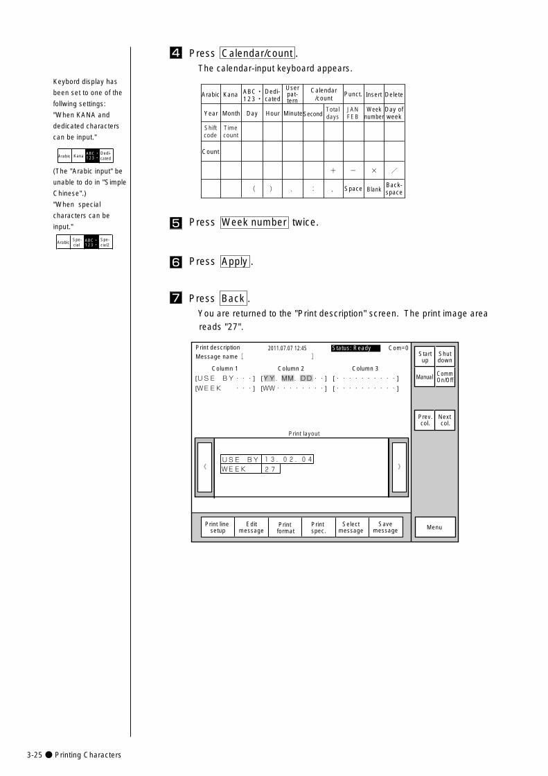
3-25● Printing Characters
4 Press Calendar/count .The calendar-input keyboard appears.
TotaldaysYear Month Day Hour Minute
Count
Calendar/countKanaArabic Dedi-
cated
Userpat-tern
Punct. Insert Delete
Space BlankBack-space
ABC・123・�
SecondJANFEB
+� -� � /�
(� )� .� :� ,�
Weeknumber
Day ofweek
Shiftcode
Timecount
5 Press Week number twice.
6 Press Apply .
Press Back .You are returned to the "Print description" screen. The print image area
reads "27".
7
》《USE BY
27�WEEK�
13.02.04�
Column 1 Column 2 Column 3
[USE BY・・・] [YY.MM.DD・・] [・・・・・・・・・・]
[WEEK ・・・] [WW・・・・・・・・] [・・・・・・・・・・]
Print description 2011.07.07 12:45Message name[ ]
Manual
MenuPrint format
Print spec.
Status: Ready Com=0
Prev.col.
Next col.
Print layout
Selectmessage
Startup
Shutdown
Print line setup
Editmessage
CommOn/Off
Savemessage
Keybord display has
been set to one of the
follwing settings:
"When KANA and
dedicated characters
can be input."
KanaDedi-cated
ABC・123・�Arabic
(The "Arabic input" be
unable to do in "Simple
Chinese".)
"When special
characters can be
input."
Spe-cial
Spe-cial2
ABC・123・�Arabic
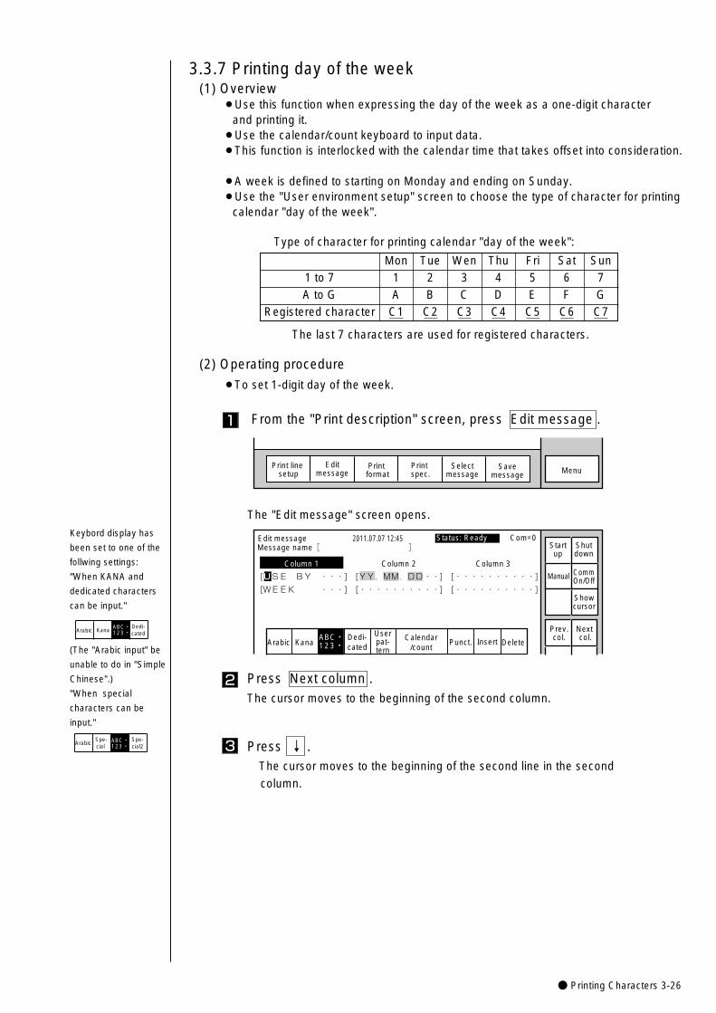
● Printing Characters 3-26
(1) Overview¡Use this function when expressing the day of the week as a one-digit character
and printing it.¡Use the calendar/count keyboard to input data.¡This function is interlocked with the calendar time that takes offset into consideration.
¡A week is defined to starting on Monday and ending on Sunday.¡Use the "User environment setup" screen to choose the type of character for printing
calendar "day of the week".
3.3.7 Printing day of the week
A to G1 to 7
Mon Tue Wen Thu Fri Sat Sun1 2 3 4 5 6 7A B C D E F G
Registered character C1 C2 C3 C4 C5 C6 C7
1
(2) Operating procedure
¡To set 1-digit day of the week.
From the "Print description" screen, press Edit message .
The "Edit message" screen opens.
Type of character for printing calendar "day of the week":
The last 7 characters are used for registered characters.
MenuSelectmessage
Print line setup
Editmessage
Print format
Print spec.
Savemessage
KanaArabicDedi-cated
Userpat-tern
Calendar/count
Punct. Insert Delete
Edit message
Column 1 Column 2 Column 3
[USE BY ・・・] [YY.MM.DD・・] [・・・・・・・・・・] �
[WEEK ・・・] [・・・・・・・・・・] [・・・・・・・・・・] �
2011.07.07 12:45
ABC・123・�
Manual
Showcursor
Prev.col.
Next col.
Status: Ready Com=0 Message name[ ] Start
upShutdown
CommOn/Off
Press Next column .The cursor moves to the beginning of the second column.
2
Press ↓ .The cursor moves to the beginning of the second line in the second
column.
3
Keybord display has
been set to one of the
follwing settings:
"When KANA and
dedicated characters
can be input."
KanaDedi-cated
ABC・123・�Arabic
(The "Arabic input" be
unable to do in "Simple
Chinese".)
"When special
characters can be
input."
Spe-cial
Spe-cial2
ABC・123・�Arabic
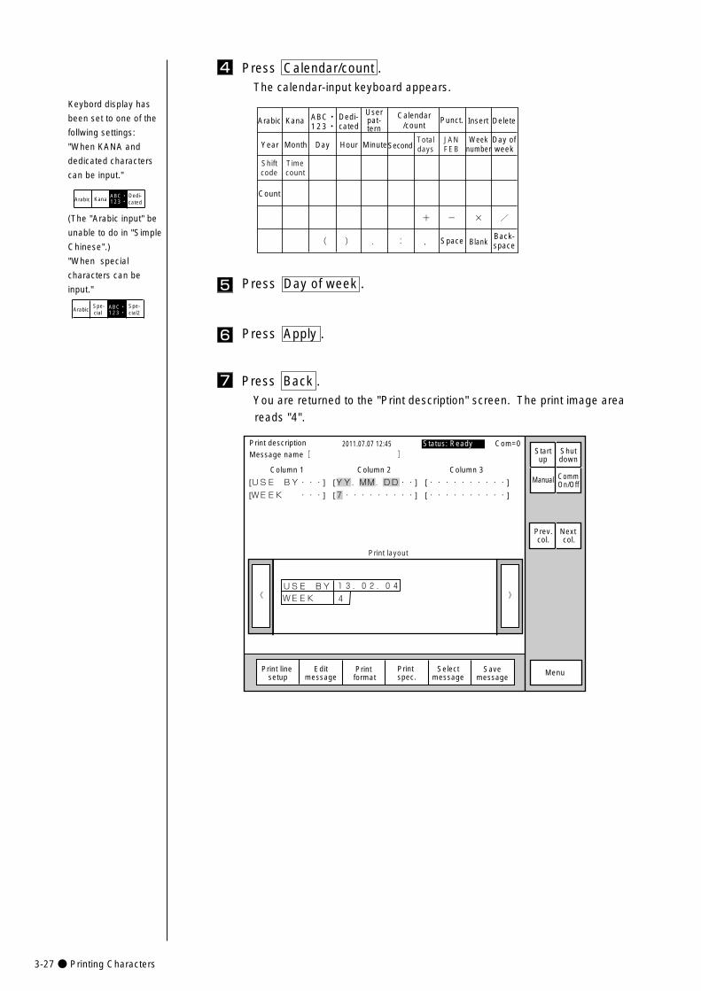
3-27● Printing Characters
4 Press Calendar/count .The calendar-input keyboard appears.
TotaldaysYear Month Day Hour Minute
Count
Calendar/countKanaArabic Dedi-
cated
Userpat-tern
Punct. Insert Delete
Space BlankBack-space
ABC・123・�
SecondJANFEB
+� -� � /�
(� )� .� :� ,�
Weeknumber
Day ofweek
Shiftcode
Timecount
5 Press Day of week .
6 Press Apply .
Press Back .You are returned to the "Print description" screen. The print image area
reads "4".
7
》《USE BY
4�WEEK�
13.02.04�
Column 1 Column 2 Column 3
[USE BY・・・] [YY.MM.DD・・] [・・・・・・・・・・]
[WEEK ・・・] [7・・・・・・・・・] [・・・・・・・・・・]
Print description 2011.07.07 12:45Message name[ ]
Manual
MenuPrint format
Print spec.
Status: Ready Com=0
Prev.col.
Next col.
Print layout
Selectmessage
Startup
Shutdown
Print line setup
Editmessage
CommOn/Off
Savemessage
Keybord display has
been set to one of the
follwing settings:
"When KANA and
dedicated characters
can be input."
KanaDedi-cated
ABC・123・�Arabic
(The "Arabic input" be
unable to do in "Simple
Chinese".)
"When special
characters can be
input."
Spe-cial
Spe-cial2
ABC・123・�Arabic
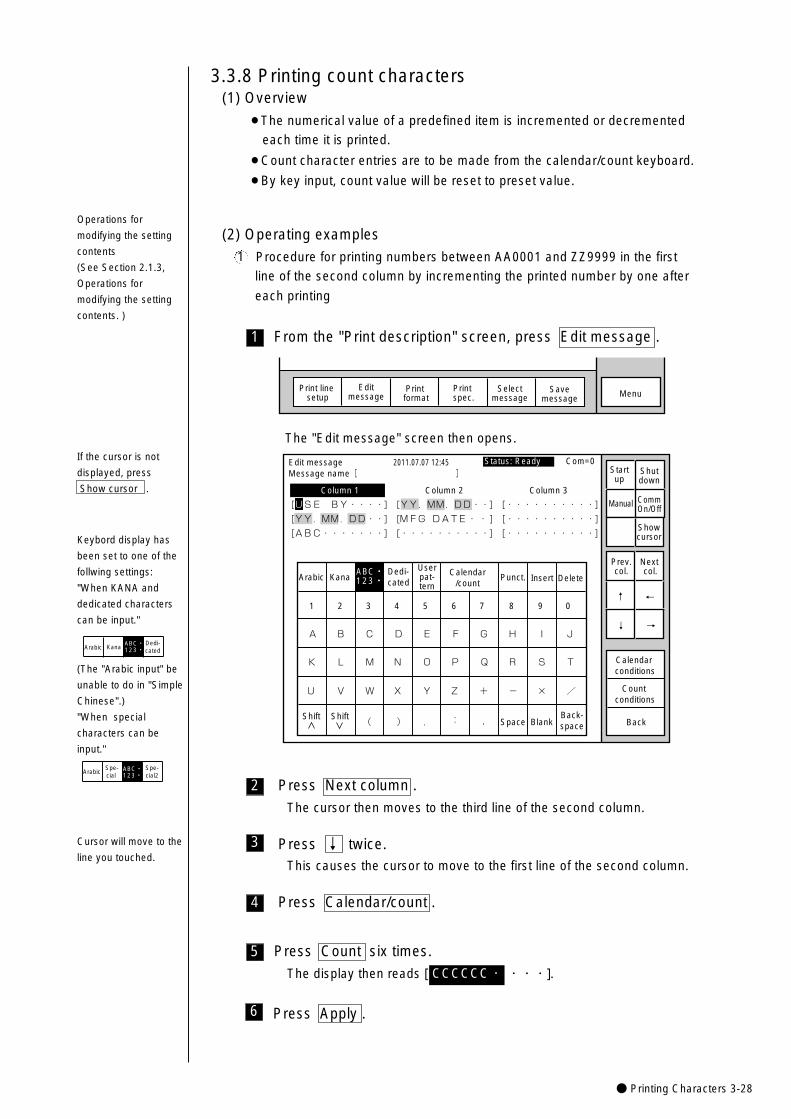
● Printing Characters 3-28
1
(1) Overview
¡The numerical value of a predefined item is incremented or decremented
each time it is printed.
¡Count character entries are to be made from the calendar/count keyboard.
¡By key input, count value will be reset to preset value.
3.3.8 Printing count characters
(2) Operating examples
Procedure for printing numbers between AA0001 and ZZ9999 in the first
line of the second column by incrementing the printed number by one after
each printing
From the "Print description" screen, press Edit message .
MenuSelectmessage
Print line setup
Editmessage
Print format
Print spec.
Savemessage
KanaArabicDedi-cated
Userpat-tern
Calendar/count
Punct. Insert Delete
K
U
A
L
V
B
M
W
C
N
X
D
O
Y
E
P
Z
F
Q
+
G
R
-
H
S
×
I
T
/
J
Space BlankBack-space( ) . : ,
Edit message
Column 1 Column 2 Column 3
[USE BY・・・・] [YY.MM.DD・・] [・・・・・・・・・・] �
[YY.MM.DD・・] [M F G D A T E・・ ] [・・・・・・・・・・] �
[ABC・・・・・・・] [・・・・・・・・・・] [・・・・・・・・・・] �
2011.07.07 12:45
Back
Calendar conditions
Count conditions
1 2 3 4 5 6 7 8 9 0
ABC・123・�
Manual
Showcursor
Prev.col.
Next col.
↓
↑
→
←
Status: Ready Com=0 Message name[ ] Start
upShutdown
CommOn/Off
Shift Shift
The "Edit message" screen then opens.
1
If the cursor is not
displayed, press
Show cursor .
Press Count six times.
The display then reads [ ・・・].CCCCCC・
2 Press Next column .
The cursor then moves to the third line of the second column.
5
4
3 Press ↓ twice.This causes the cursor to move to the first line of the second column.
Press Calendar/count .
6 Press Apply .
Operations for
modifying the setting
contents
(See Section 2.1.3,
Operations for
modifying the setting
contents. )
Cursor will move to the
line you touched.
Keybord display has
been set to one of the
follwing settings:
"When KANA and
dedicated characters
can be input."
KanaDedi-cated
ABC・123・�Arabic
(The "Arabic input" be
unable to do in "Simple
Chinese".)
"When special
characters can be
input."
Spe-cial
Spe-cial2
ABC・123・�Arabic
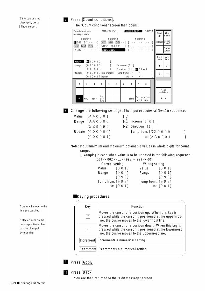
3-29● Printing Characters
10
8
7 Press Count conditions .The "Count conditions" screen then opens.
1 2 3 4 5 6 7 8 9 0
Incre-ment
Decre-ment
Count conditions
Column 1 Column 2 Column 3
[USE BY・・・・] [YY.MM.DD・・] [・・・・・・・・・・] �
[YY.MM.DD・・] [MFG DATE・・] [・・・・・・・・・・] �
[ABC・・・・・・・] [CCCCCC・・・・] [・・・・・・・・・・]
2011.07.07 12:45
Back
Value [000000 ]
Range [000000 ] Increment [01]
[999999 ] Direction [1] (1:up 2:down)
Update [000000](in progress) Jump from:[・・・・・・ ]
[000001](unit) to:[・・・・・・ ]
ABC・�abc・� Blank123・�
Manual
Showcursor
Prev.item
Next item
↓
↑
→
←
Status: Ready Com=0 Message name[ ] Start
upShutdown
CommOn/Off
Userpat-tern
Nextconditions
Change the following settings. The input executes in sequence.
Value [AA0001 ]
Range [AA0000 ] increment [01]
[ZZ9999 ] Direction [1]
Update [000000] Jump from: [ZZ9999 ]
[000001] to: [AA0001 ]
Note: Input minimum and maximum obtainable values in whole digits for countrange.[Example] In case when value is to be updated in the following sequence:
001 -> 002 -> ... -> 998 -> 999 -> 001 Correct setting Wrong setting
Value [001] Value [001]Range [000] Range [001]
[999] [999]Jump from: [999] Jump from: [999]
to: [001] to: [001]
■Keying procedures
Key Function
↑
↓
Increment
Decrement
Moves the cursor one position up. When this key is pressed while the cursor is positioned at the uppermostline, the cursor moves to the lowermost line.
Moves the cursor one position down. When this key is pressed while the cursor is positioned at the lowermostline, the cursor moves to the uppermost line.
Increments a numerical setting.
Decrements a numerical setting.
Press Back .
You are then returned to the "Edit message" screen.
bc
a
9 Press Apply .
a b c
If the cursor is not
displayed, press
Show cursor .
Cursor will move to the
line you touched.
Selected item on the
cursor-positioned line
can be changed
by touching.
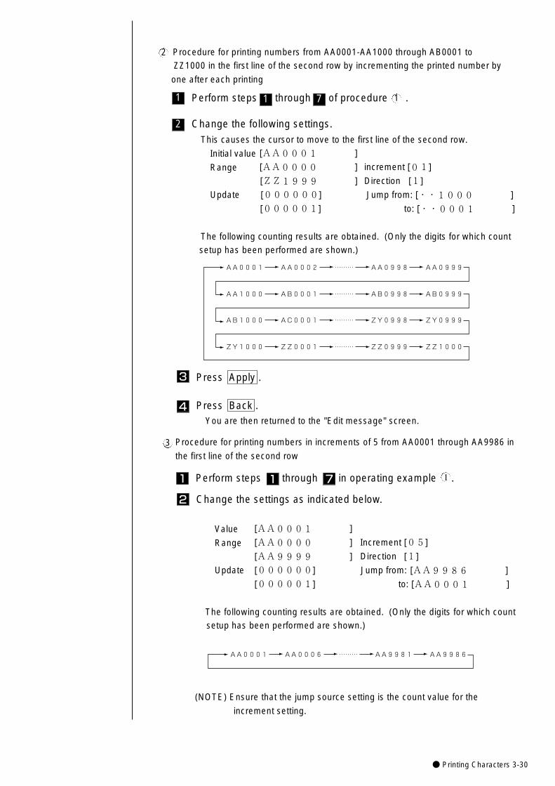
● Printing Characters 3-30
Procedure for printing numbers from AA0001-AA1000 through AB0001 to
ZZ1000 in the first line of the second row by incrementing the printed number by
one after each printing
2
1 Perform steps through of procedure .7 1
2 Change the following settings.
This causes the cursor to move to the first line of the second row.
Initial value [AA0001 ]
Range [AA0000 ] increment [01]
[ZZ1999 ] Direction [1]
Update [000000] Jump from: [・・1000 ]
[000001] to: [・・0001 ]
The following counting results are obtained. (Only the digits for which count
setup has been performed are shown.)
AA0001 AA0002 ……… AA0998 AA0999�
AB1000 AC0001 ……… ZY0998 ZY0999�
AA1000 AB0001 ……… AB0998 AB0999�
ZY1000 ZZ0001 ……… ZZ0999 ZZ1000�
1
Procedure for printing numbers in increments of 5 from AA0001 through AA9986 in
the first line of the second row3
1 Perform steps through in operating example .7 1
2 Change the settings as indicated below.
Value [AA0001 ]
Range [AA0000 ] Increment [05]
[AA9999 ] Direction [1]
Update [000000] Jump from: [AA9986 ]
[000001] to: [AA0001 ]
The following counting results are obtained. (Only the digits for which count
setup has been performed are shown.)
AA0001 AA0006 ……… AA9981 AA9986�
1
(NOTE) Ensure that the jump source setting is the count value for the
increment setting.
4 Press Back .You are then returned to the "Edit message" screen.
3 Press Apply .
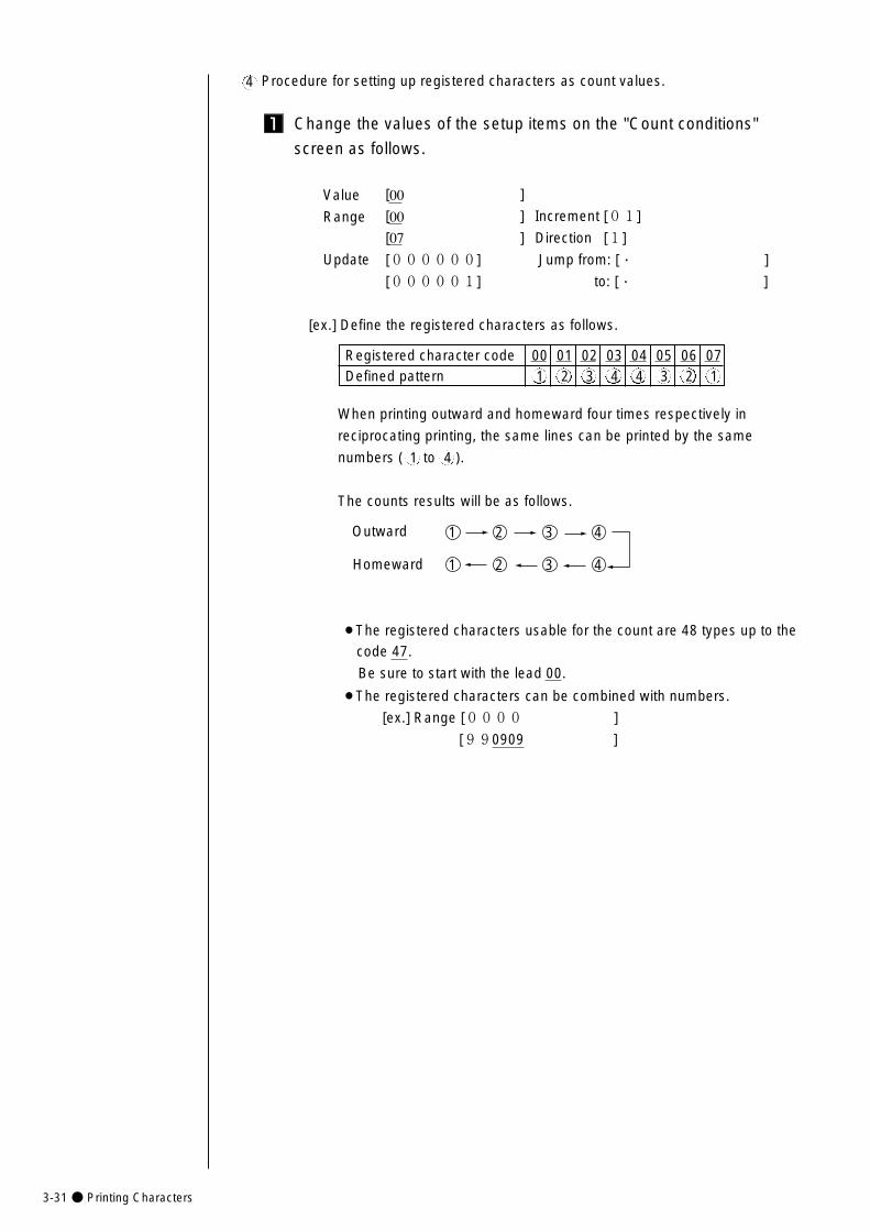
3-31● Printing Characters
Procedure for setting up registered characters as count values.4
1 Change the values of the setup items on the "Count conditions"
screen as follows.
Value [00 ]
Range [00 ] Increment [01]
[07 ] Direction [1]
Update [000000] Jump from: [・ ]
[000001] to: [・ ]
[ex.] Define the registered characters as follows.
Outward
Homeward
1 2 3 4
1 2 3 4
¡The registered characters usable for the count are 48 types up to the
code 47.
Be sure to start with the lead 00.
¡The registered characters can be combined with numbers.
[ex.] Range [0000 ]
[990909 ]
Registered character code 00 01 02 03 04 05 06 07Defined pattern 1 2 3 4 4 3 2 1
When printing outward and homeward four times respectively in
reciprocating printing, the same lines can be printed by the same
numbers ( to ).
The counts results will be as follows.
1 4
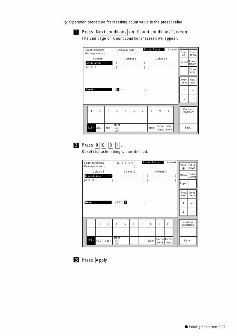
● Printing Characters 3-32
Operation procedure for resetting count value to the preset value5
1 Press Next conditions on "Count conditions" screen.The 2nd page of "Count conditions" screen will appear.
1 2 3 4 5 6 7 8 9 0
Incre-ment
Decre-ment
Count conditions
Column 1 Column 2 Column 3
[CCCCCC・・・・] [・・・・・・・・・・] [・・・・・・・・・・] �
[ABCD・・・・・・] [・・・・・・・・・・] [・・・・・・・・・・]
2011.07.07 12:45
Back
Reset [・・・・ ] �
ABC・�abc・� Blank123・�
Manual
Showcursor
Prev.item
Next item
↓
↑
→
←
Status: Ready Com=0 Message name[ ] Start
upShutdown
CommOn/Off
Userpat-tern
Previousconditions
2 Press 0 0 0 1 .Reset character string is thus defined.
1 2 3 4 5 6 7 8 9 0
Incre-ment
Decre-ment
Count conditions
Column 1 Column 2 Column 3
[CCCCCC・・・・] [・・・・・・・・・・] [・・・・・・・・・・] �
[ABCD・・・・・・] [・・・・・・・・・・] [・・・・・・・・・・]
2011.07.07 12:45
Back
Reset [0001 ] �
ABC・�abc・� Blank123・�
Manual
Apply
Prev.item
Next item
↓
↑
→
←
Status: Ready Com=0 Message name[ ] Start
upShutdown
CommOn/Off
Userpat-tern
Previousconditions
3 Press Apply .
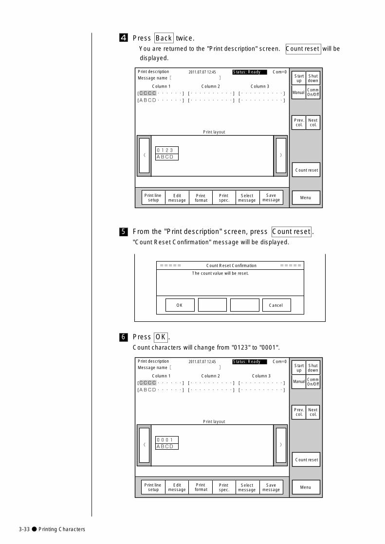
3-33● Printing Characters
Press Back twice.You are returned to the "Print description" screen. Count reset will be
displayed.
4
》《0123�ABCD�
Column 1 Column 2 Column 3
[CCCC・・・・・・] [・・・・・・・・・・] [・・・・・・・・・・]
[ABCD・・・・・・] [・・・・・・・・・・] [・・・・・・・・・・]
Print description 2011.07.07 12:45Message name[ ]
Manual
MenuPrint format
Print spec.
Status: Ready Com=0
Prev.col.
Next col.
Print layout
Selectmessage
Startup
Shutdown
Print line setup
Editmessage
CommOn/Off
Savemessage
Count reset
5 From the "Print description" screen, press Count reset ."Count Reset Confirmation" message will be displayed.
===== Count Reset Confirmation =====
The count value will be reset.
OK Cancel
6 Press OK .Count characters will change from "0123" to "0001".
》《0001�ABCD�
Column 1 Column 2 Column 3
[CCCC・・・・・・] [・・・・・・・・・・] [・・・・・・・・・・]
[ABCD・・・・・・] [・・・・・・・・・・] [・・・・・・・・・・]
Print description 2011.07.07 12:45Message name[ ]
Manual
MenuPrint format
Print spec.
Status: Ready Com=0
Prev.col.
Next col.
Print layout
Selectmessage
Startup
Shutdown
Print line setup
Editmessage
CommOn/Off
Savemessage
Count reset
● Printing Characters 3-34
(1) Overview
¡Enter from the Arabic character keyboard.
¡The Arabic characters cannot be entered in character size 5×5, 9×8 and 7×10.
¡Entering an Arabic character will move the cursor to the left.
3.3.9 Printing Arabic characters
(The "Arabic input" be
unable to do in "Simple
Chinese".)
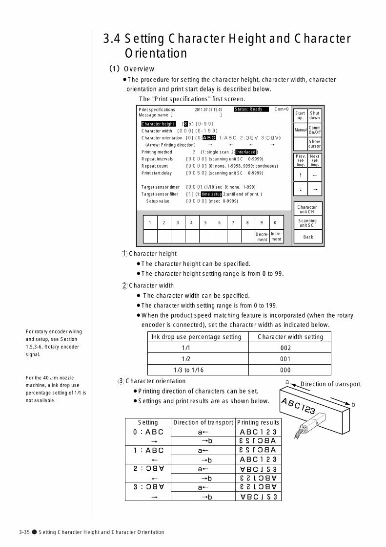
3-35● Setting Character Height and Character Orientation
(1)Overview¡The procedure for setting the character height, character width, character
orientation and print start delay is described below.
The "Print specifications" first screen.
3.4 Setting Character Height and CharacterOrientation
Print specifications 2011.07.07 12:45
Character height [85] (0-99)
Character width [000] (0-199)
Character orientation [0] (0:ABC 1:ABC 2: 3: )
(Arrow: Printing direction) → ← ← →
Printing method 2 (1: single scan 2: Interlaced )
Repeat intervals [0000] (scanning unit SC 0-9999)
Repeat count [0000] (0: none, 1-9998, 9999: continuous)
Print start delay [0050] (scanning unit SC 0-9999)
Target sensor timer [000] (1/10 sec 0: none, 1-999)
Target sensor filter [1] (1: time setup 2:until end of print. )
Setup value [0000] (msec 0-9999)
Back
1 2 3 4 5 6 7 8 9 0
Incre-ment
Decre-ment
Characterunit CH
Scanning unit SC
ABC ABC
Manual
Showcursor
Status: Ready Com=0 Message name[ ] Start
upShutdown
CommOn/Off
Prev.set-tings
Next set-tings
↓�
↑�
→�
←�
Character height
¡The character height can be specified.
¡The character height setting range is from 0 to 99.
1
Character width
¡ The character width can be specified.
¡The character width setting range is from 0 to 199.
¡When the product speed matching feature is incorporated (when the rotary
encoder is connected), set the character width as indicated below.
2
For rotary encoder wiring
and setup, see Section
1.5.3-6, Rotary encoder
signal.
Direction of transport
ABC123b
aCharacter orientation
¡Printing direction of characters can be set.
¡Settings and print results are as shown below.
3
Ink drop use percentage setting Character width setting
1/1 002
1/2 001
1/3 to 1/16 000For the 40μm nozzle
machine, a ink drop use
percentage setting of 1/1 is
not available.
Setting
0:ABC→
1:ABC←
2:
←3:
→
Direction of transport Printing results
a←→ba←
a←
a←
→b
→b
→b
ABC123
ABC123
ABC123�ABC123�
ABC123�
ABC123�
ABC
ABCABC123ABC123
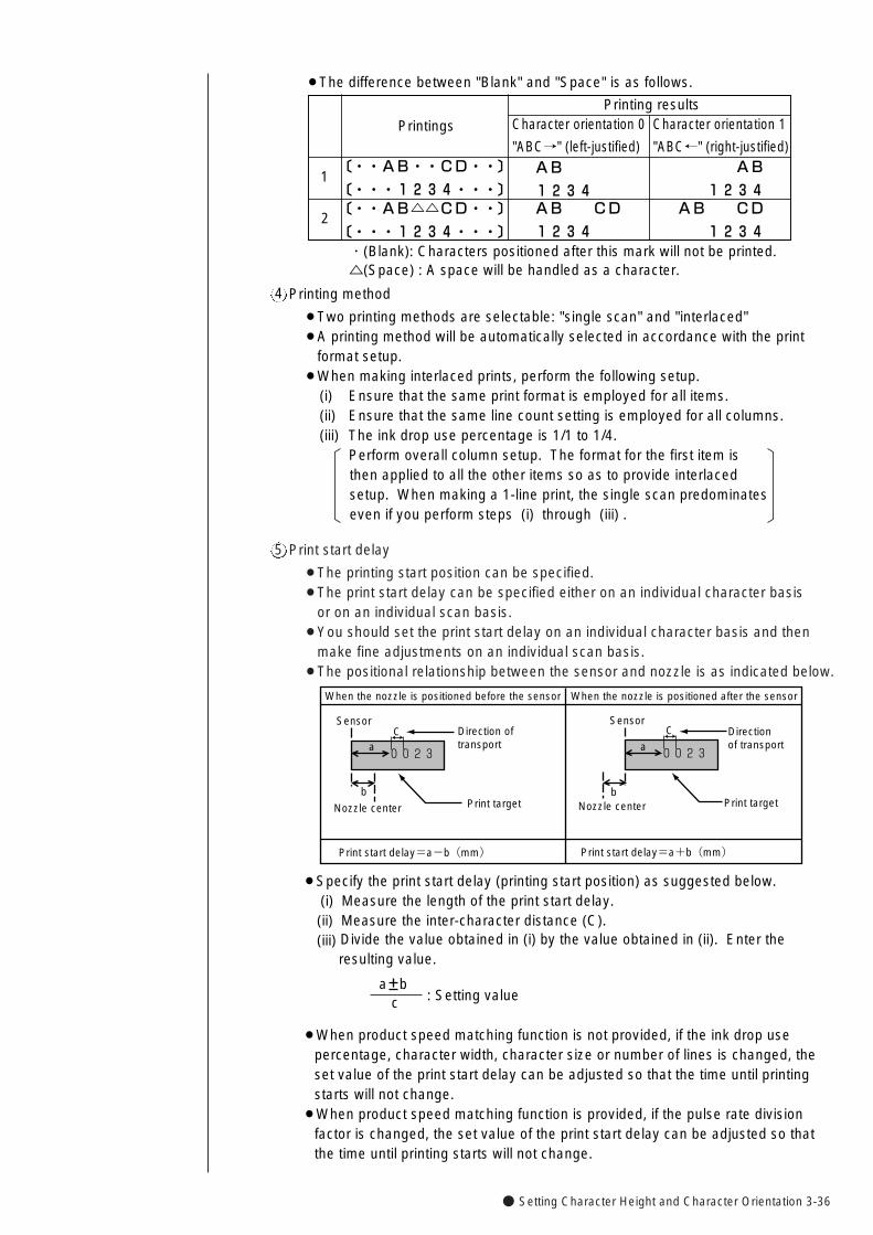
● Setting Character Height and Character Orientation 3-36
Print start delay
¡The printing start position can be specified.¡The print start delay can be specified either on an individual character basis
or on an individual scan basis.¡You should set the print start delay on an individual character basis and then
make fine adjustments on an individual scan basis.¡The positional relationship between the sensor and nozzle is as indicated below.
5
When the nozzle is positioned before the sensor When the nozzle is positioned after the sensor
SensorDirection of transport
Print targetNozzle center
SensorDirectionof transport
Print targetNozzle center
a
b
a
b
Print start delay=a-b(mm) Print start delay=a+b(mm)
0023
C C
0023
¡Specify the print start delay (printing start position) as suggested below.(i) Measure the length of the print start delay.(ii) Measure the inter-character distance (C).(iii) Divide the value obtained in (i) by the value obtained in (ii). Enter the
resulting value.
Printing method
¡Two printing methods are selectable: "single scan" and "interlaced"¡A printing method will be automatically selected in accordance with the print
format setup.¡When making interlaced prints, perform the following setup.
(i) Ensure that the same print format is employed for all items.(ii) Ensure that the same line count setting is employed for all columns.(iii) The ink drop use percentage is 1/1 to 1/4.
Perform overall column setup. The format for the first item is then applied to all the other items so as to provide interlaced setup. When making a 1-line print, the single scan predominates even if you perform steps (i) through (iii) .
4
¡The difference between "Blank" and "Space" is as follows.
Character orientation 0
"ABC→" (left-justified)
1AB
1234
Printings
〔・・AB・・CD・・〕
〔・・・1234・・・〕
2〔・・AB△△CD・・〕
〔・・・1234・・・〕
Printing resultsCharacter orientation 1
"ABC←" (right-justified)
AB CD
1234
AB
1234AB CD
1234・(Blank): Characters positioned after this mark will not be printed.△(Space) : A space will be handled as a character.
a bc : Setting value
¡When product speed matching function is not provided, if the ink drop use percentage, character width, character size or number of lines is changed, the set value of the print start delay can be adjusted so that the time until printing starts will not change.
¡When product speed matching function is provided, if the pulse rate division factor is changed, the set value of the print start delay can be adjusted so that the time until printing starts will not change.
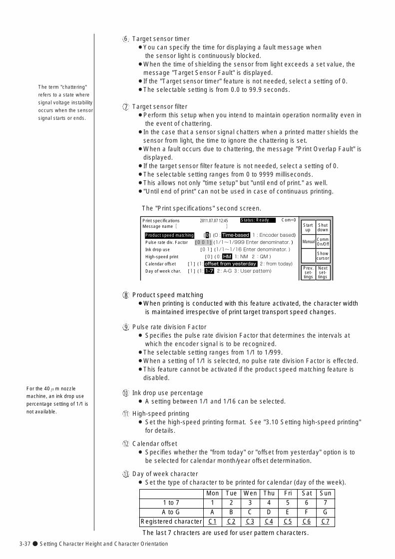
3-37● Setting Character Height and Character Orientation
6
7
The term "chattering"
refers to a state where
signal voltage instability
occurs when the sensor
signal starts or ends.
Target sensor timer¡You can specify the time for displaying a fault message when
the sensor light is continuously blocked.¡When the time of shielding the sensor from light exceeds a set value, the
message "Target Sensor Fault" is displayed.¡If the "Target sensor timer" feature is not needed, select a setting of 0.¡The selectable setting is from 0.0 to 99.9 seconds.
Target sensor filter¡Perform this setup when you intend to maintain operation normality even in
the event of chattering.¡In the case that a sensor signal chatters when a printed matter shields the
sensor from light, the time to ignore the chattering is set.¡When a fault occurs due to chattering, the message "Print Overlap Fault" is
displayed.¡If the target sensor filter feature is not needed, select a setting of 0.¡The selectable setting ranges from 0 to 9999 milliseconds.¡This allows not only "time setup" but "until end of print." as well. ¡"Until end of print" can not be used in case of continuaus printing.
The "Print specifications" second screen.
9 Pulse rate division Factor¡ Specifies the pulse rate division Factor that determines the intervals at
which the encoder signal is to be recognized.¡The selectable setting ranges from 1/1 to 1/999.¡When a setting of 1/1 is selected, no pulse rate division Factor is effected.¡This feature cannot be activated if the product speed matching feature is
disabled.
10 Ink drop use percentage¡ A setting between 1/1 and 1/16 can be selected.
11 High-speed printing¡ Set the high-speed printing format. See "3.10 Setting high-speed printing"
for details.
12 Calendar offset¡ Specifies whether the "from today" or "offset from yesterday" option is to
be selected for calendar month/year offset determination.
13 Day of week character¡ Set the type of character to be printed for calendar (day of the week).
For the 40μm nozzle
machine, an ink drop use
percentage setting of 1/1 is
not available.
�
Print specifications 2011.07.07 12:45
Manual
Showcursor
Startup
Shutdown
CommOn/Off
Status: Ready Com=0 Message name[ ]
Product speed matching [0] (0 : Time-based 1 : Encoder based)�
Pulse rate div. Factor [001] (1/1~1/999 Enter denominator. )
Ink drop use [01] (1/1~1/16 Enter denominator. )
High-speed print [0] (0: HM 1: NM 2:QM )�
Calendar offset [1] (1: offset from yesterday 2: from today)�
Day of week char. [1] (1: 1-7 2: A-G 3: User pattern)Prev.set-tings
Nextset-tings
8 Product speed matching¡When printing is conducted with this feature activated, the character width
is maintained irrespective of print target transport speed changes.
Mon Tue Wen Thu Fri Sat Sun1 2 3 4 5 6 7A B C D E F G
C1 C2 C3 C4 C5 C6 C7
1 to 7A to G
Registered character
The last 7 chracters are used for user pattern characters.
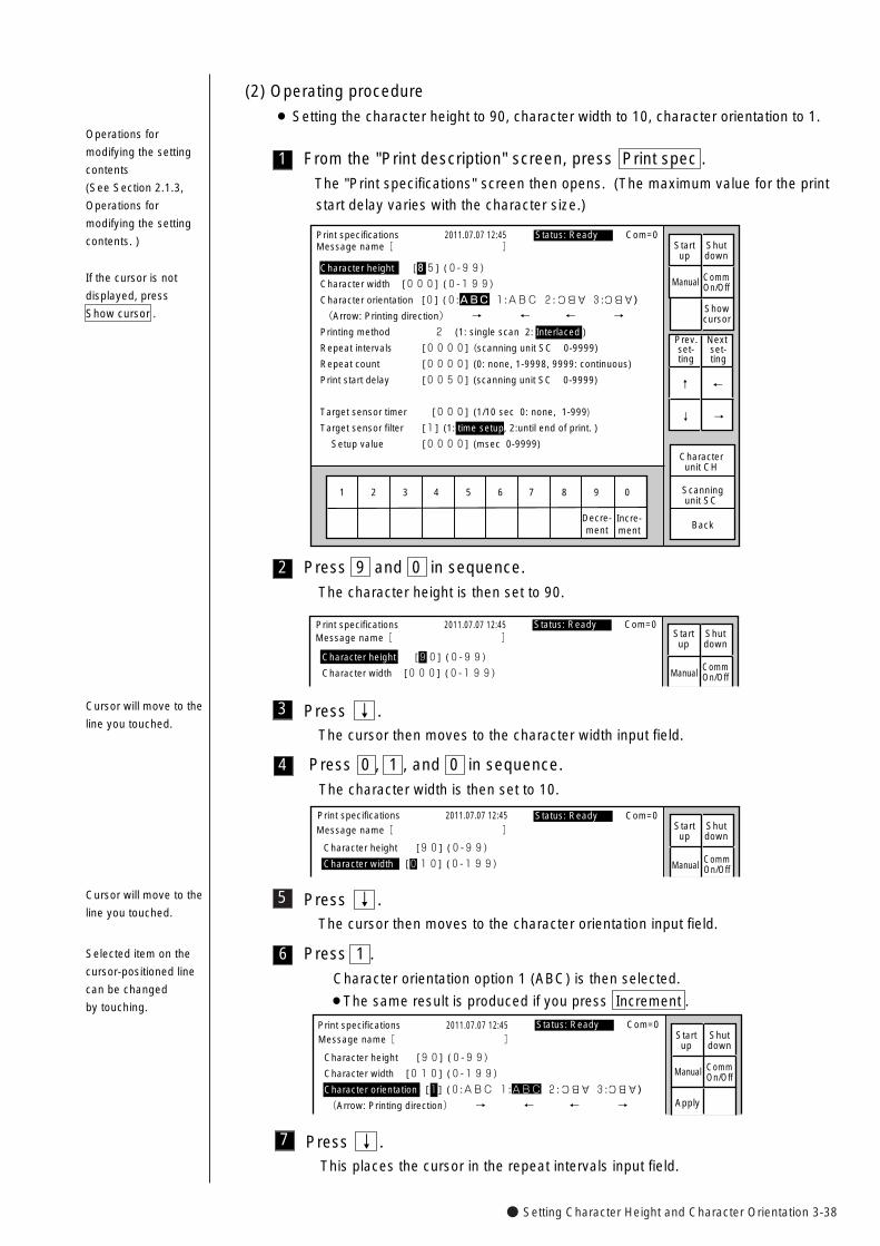
● Setting Character Height and Character Orientation 3-38
5
4
3 Press ↓ .The cursor then moves to the character width input field.
Press 0 , 1 , and 0 in sequence.
The character width is then set to 10.
Press ↓ .The cursor then moves to the character orientation input field.
Print specifications 2011.07.07 12:45
Manual
Character height [90] (0-99)
Character width [010] (0-199)
Status: Ready Com=0
Message name[ ] Startup
Shutdown
CommOn/Off
7
6
Press ↓ .This places the cursor in the repeat intervals input field.
Press 1 .
Character orientation option 1 (ABC) is then selected.
¡The same result is produced if you press Increment .
�
Print specifications 2011.07.07 12:45
Character height [90] (0-99)
Character width [010] (0-199)
Character orientation [1] (0:ABC 1:ABC 2: 3: )
(Arrow: Printing direction) → ← ← →
ABC ABC
Manual
Apply
Status: Ready Com=0
Message name[ ] Startup
Shutdown
CommOn/Off
2
1
(2) Operating procedure
¡ Setting the character height to 90, character width to 10, character orientation to 1.
From the "Print description" screen, press Print spec .
The "Print specifications" screen then opens. (The maximum value for the print
start delay varies with the character size.)
Print specifications 2011.07.07 12:45
Back
1 2 3 4 5 6 7 8 9 0
Incre-ment
Decre-ment
Characterunit CH
Scanning unit SC
Manual
Showcursor
Status: Ready Com=0Message name[ ] Start
upShutdown
CommOn/Off
Character height [85] (0-99)
Character width [000] (0-199)
Character orientation [0] (0:ABC 1:ABC 2: 3: )
(Arrow: Printing direction) → ← ← →
Printing method 2 (1: single scan 2: Interlaced )
Repeat intervals [0000] (scanning unit SC 0-9999)
Repeat count [0000] (0: none, 1-9998, 9999: continuous)
Print start delay [0050] (scanning unit SC 0-9999)
Target sensor timer [000] (1/10 sec 0: none, 1-999)
Target sensor filter [1] (1: time setup, 2:until end of print. )
Setup value [0000] (msec 0-9999)
ABC ABC
Prev.set-ting
Next set-ting
↓
↑
→
←
Press 9 and 0 in sequence.
The character height is then set to 90.
Print specifications 2011.07.07 12:45
Manual
Character height [90] (0-99)
Character width [000] (0-199)
Status: Ready Com=0 Message name[ ] Start
upShutdown
CommOn/Off
If the cursor is not
displayed, press
Show cursor .
Operations for
modifying the setting
contents
(See Section 2.1.3,
Operations for
modifying the setting
contents. )
Cursor will move to the
line you touched.
Selected item on the
cursor-positioned line
can be changed
by touching.
Cursor will move to the
line you touched.
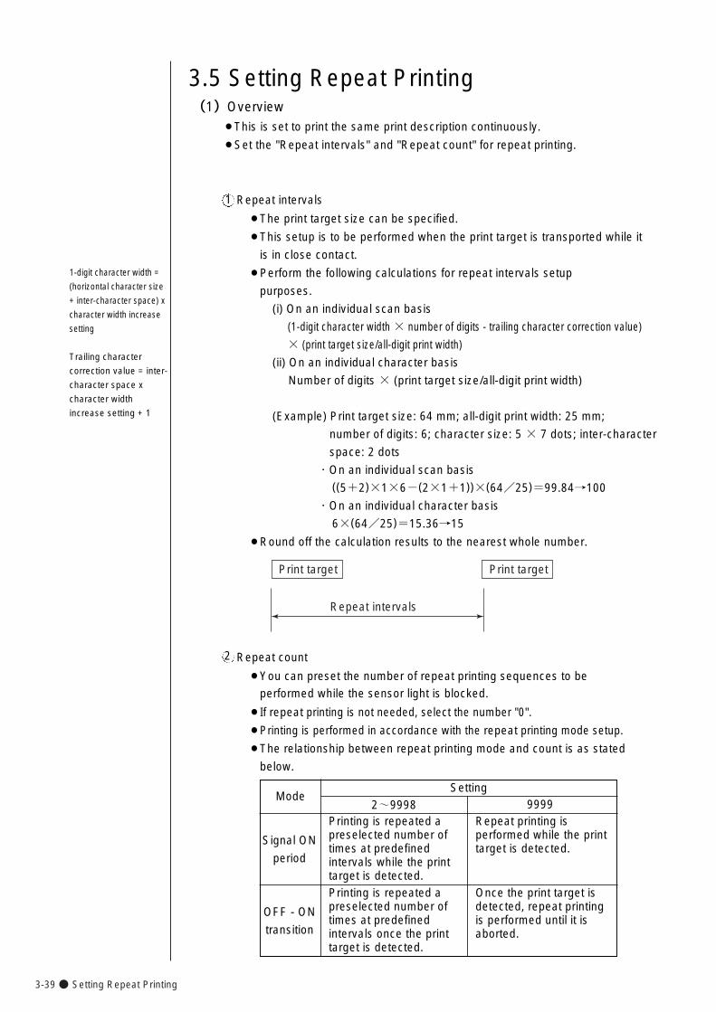
3-39● Setting Repeat Printing
3.5 Setting Repeat Printing (1)Overview
¡This is set to print the same print description continuously.
¡Set the "Repeat intervals" and "Repeat count" for repeat printing.
Repeat intervals
¡The print target size can be specified.
¡This setup is to be performed when the print target is transported while it
is in close contact.
¡Perform the following calculations for repeat intervals setup
purposes.
(i) On an individual scan basis
(1-digit character width × number of digits - trailing character correction value)
× (print target size/all-digit print width)
(ii) On an individual character basis
Number of digits × (print target size/all-digit print width)
(Example) Print target size: 64 mm; all-digit print width: 25 mm;
number of digits: 6; character size: 5 × 7 dots; inter-character
space: 2 dots
・On an individual scan basis((5+2)×1×6-(2×1+1))×(64/25)=99.84→100
・On an individual character basis
6×(64/25)=15.36→15
¡Round off the calculation results to the nearest whole number.
1
1-digit character width =
(horizontal character size
+ inter-character space) x
character width increase
setting
Trailing character
correction value = inter-
character space x
character width
increase setting + 1
Repeat count
¡You can preset the number of repeat printing sequences to be
performed while the sensor light is blocked.
¡If repeat printing is not needed, select the number "0".
¡Printing is performed in accordance with the repeat printing mode setup.
¡The relationship between repeat printing mode and count is as stated
below.
2
Mode
Signal ON
period
OFF - ON
transition
Setting2~9998
Printing is repeated apreselected number oftimes at predefinedintervals while the printtarget is detected.
Repeat printing isperformed while the printtarget is detected.
9999
Printing is repeated apreselected number oftimes at predefinedintervals once the printtarget is detected.
Once the print target isdetected, repeat printingis performed until it isaborted.
Repeat intervals
Print target Print target
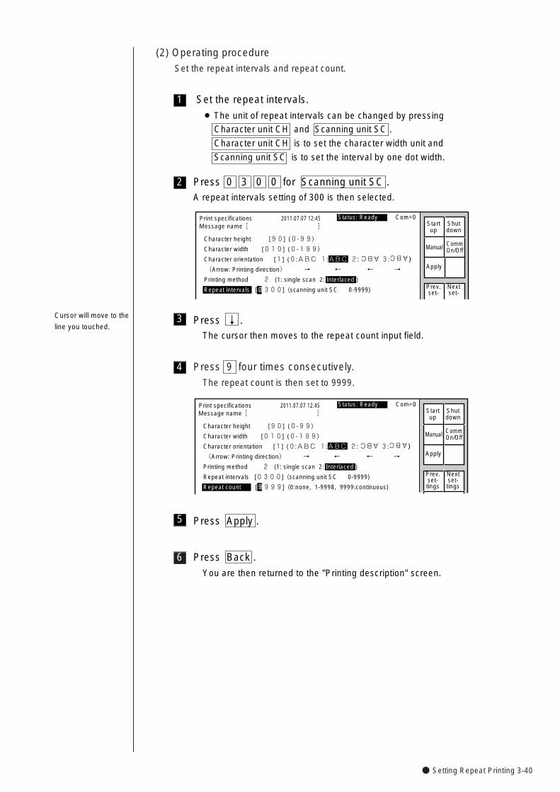
● Setting Repeat Printing 3-40
(2) Operating procedure
Set the repeat intervals and repeat count.
Press 9 four times consecutively.
The repeat count is then set to 9999.
6
4
3
2
1 Set the repeat intervals.
¡ The unit of repeat intervals can be changed by pressing
Character unit CH and Scanning unit SC .
Character unit CH is to set the character width unit and
Scanning unit SC is to set the interval by one dot width.
Press 0 3 0 0 for Scanning unit SC .A repeat intervals setting of 300 is then selected.
�
Print specifications 2011.07.07 12:45
Character height [90] (0-99)
Character width [010] (0-199)
Character orientation [1] (0:ABC 1:ABC 2: 3: )
(Arrow: Printing direction) → ← ← →
Printing method 2 (1: single scan 2: Interlaced )
Repeat intervals [0300] (scanning unit SC 0-9999)
ABC ABC
Manual
Apply
Status: Ready Com=0Message name[ ] Start
upShutdown
Prev.set-
Nextset-
CommOn/Off
Press ↓ .The cursor then moves to the repeat count input field.
�
Print specifications 2011.07.07 12:45
Character height [90] (0-99)
Character width [010] (0-199)
Character orientation [1] (0:ABC 1:ABC 2: 3: )
(Arrow: Printing direction) → ← ← →
Printing method 2 (1: single scan 2: Interlaced )
Repeat intervals [0300] (scanning unit SC 0-9999)
Repeat count [9999] (0:none, 1-9998, 9999:continuous)
ABC ABC
Manual
Apply
Status: Ready Com=0 Message name[ ] Start
upShutdown
CommOn/Off
Prev.set-tings
Nextset-tings
Press Back .
You are then returned to the "Printing description" screen.
5 Press Apply .
Cursor will move to the
line you touched.
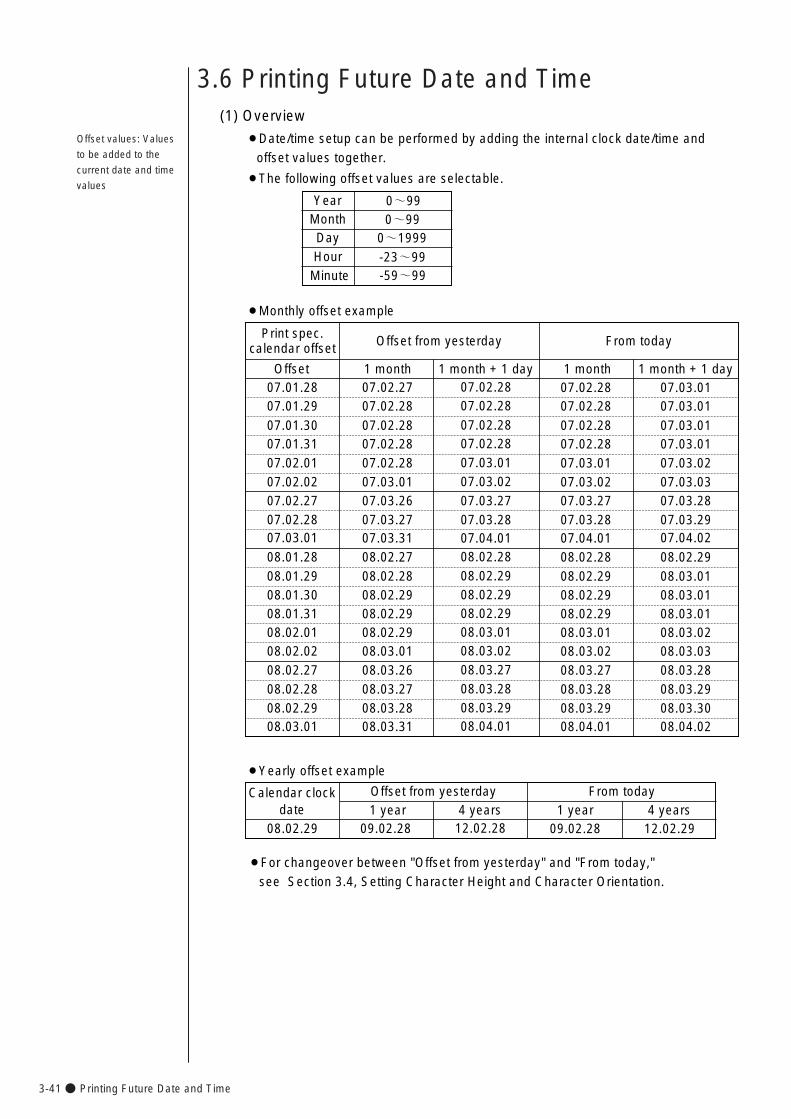
3-41● Printing Future Date and Time
3.6 Printing Future Date and Time
Offset values: Values
to be added to the
current date and time
values
YearMonth
HourDay
0~990~99
0~1999
-23~99
(1) Overview
¡Date/time setup can be performed by adding the internal clock date/time and
offset values together.
¡The following offset values are selectable.
Minute -59~99
Print spec.calendar offset
07.01.28
Offset from yesterday
1 month07.02.27 07.02.28
¡Monthly offset example
From today
07.02.28 07.03.011 month + 1 day 1 month 1 month + 1 day
07.01.29 07.02.28 07.02.28 07.02.28 07.03.01
07.01.30 07.02.28 07.02.28 07.02.28 07.03.0107.01.31 07.02.28 07.02.28 07.02.28 07.03.0107.02.01 07.02.28 07.03.01 07.03.01 07.03.0207.02.02 07.03.01 07.03.02 07.03.02 07.03.0307.02.27 07.03.26 07.03.27 07.03.27 07.03.2807.02.28 07.03.27 07.03.28 07.03.28 07.03.2907.03.01 07.03.31 07.04.01 07.04.01 07.04.02
08.01.28 08.02.27 08.02.28 08.02.28 08.02.2908.01.29 08.02.28 08.02.29 08.02.29 08.03.0108.01.30 08.02.29 08.02.29 08.02.29 08.03.0108.01.31 08.02.29 08.02.29 08.02.29 08.03.0108.02.01 08.02.29 08.03.01 08.03.01 08.03.0208.02.02 08.03.01 08.03.02 08.03.02 08.03.0308.02.27 08.03.26 08.03.27 08.03.27 08.03.2808.02.28 08.03.27 08.03.28 08.03.28 08.03.2908.02.29 08.03.28 08.03.29 08.03.29 08.03.3008.03.01 08.03.31 08.04.01 08.04.01 08.04.02
Calendar clockdate
08.02.29
Offset from yesterday1 year
09.02.28 12.02.28
¡Yearly offset example
From today
09.02.28 12.02.294 years 1 year 4 years
Offset
¡For changeover between "Offset from yesterday" and "From today,"
see Section 3.4, Setting Character Height and Character Orientation.
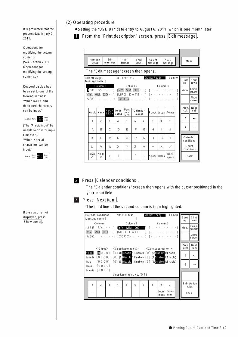
● Printing Future Date and Time 3-42
3
2
1
(2) Operating procedure
¡Setting the "USE BY" date entry to August 6, 2011, which is one month later
From the "Print description" screen, press Edit message .
It is presumed that the
present date is July 7,
2011.
MenuSelectmessage
Print line setup
Editmessage
Print format
Print spec.
Savemessage
KanaArabicDedi-cated
Userpat-tern
Calendar/count
Punct. Insert Delete
K
U
A
L
V
B
M
W
C
N
X
D
O
Y
E
P
Z
F
Q
+
G
R
-
H
S
×
I
T
/
J
Space BlankBack-space( ) . : ,
Edit message
Column 1 Column 2 Column 3
[USE BY・・・・] [YY.MM.DD・・ ] [・・・・・・・・・・]�
[YY.MM.DD・・] [MFG DATE・・] [・・・・・・・・・・] �
[ABC・・・・・・・] [CCCC・・・・・・] [・・・・・・・・・・]�
�
2011.07.07 12:45
Back
Calendar conditions
Count conditions
1 2 3 4 5 6 7 8 9 0
ABC・123・�
Manual
Showcursor
Prev.col.
Next col.
↓
↑
→
←
Status: Ready Com=0 Message name[ ] Start
upShutdown
CommOn/Off
Shift Shift
The "Edit message" screen then opens.
Press Calendar conditions .
The "Calendar conditions" screen then opens with the cursor positioned in the
year input field.
1 2 3 4 5 6 7 8 9 0
Incre-ment
Decre-ment
Calendar conditions
Column 1 Column 2 Column 3
[USE BY・・・・] [YY.MM.DD・・] [・・・・・・・・・・] �
[YY.MM.DD・・] [MFG DATE・・] [・・・・・・・・・・] �
[ABC・・・・・・・] [CCCC・・・・・・] [・・・・・・・・・・]
2011.07.07 12:45
Back
<Offset> <Substitution rules> <Zero-suppression>
Year [0000][0](0:Disable 1:Enable)[0](0:Disable 1:Enable)
Month [0000][0](0:Disable 1:Enable)[0](0:Disable 1:Enable)
Day [0000][0](0:Disable 1:Enable)[0](0:Disable 1:Enable)
Hour [0000]�
Minute [0000]
Substitution rules No. [01]
Manual
Showcursor
Prev.item
Next item
↓
↑
→
←
Status: Ready Com=0
Substitutionrules
Message name[ ] Startup
Shutdown
CommOn/Off
Press Next item .
The third line of the second column is then highlighted.If the cursor is not
displayed, press
Show cursor .
Operations for
modifying the setting
contents
(See Section 2.1.3,
Operations for
modifying the setting
contents. )
Keybord display has
been set to one of the
follwing settings:
"When KANA and
dedicated characters
can be input."
KanaDedi-cated
ABC・123・�Arabic
(The "Arabic input" be
unable to do in "Simple
Chinese".)
"When special
characters can be
input."
Spe-cial
Spe-cial2
ABC・123・�Arabic
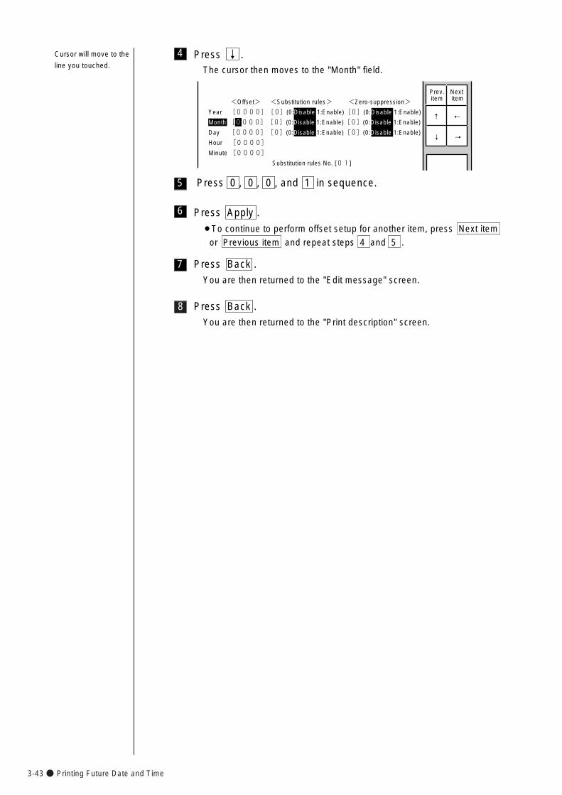
3-43● Printing Future Date and Time
8
7
5
4
Press 0 , 0 , 0 , and 1 in sequence.
Press Back .
You are then returned to the "Edit message" screen.
Press Back .
You are then returned to the "Print description" screen.
Press ↓ .The cursor then moves to the "Month" field.
<Offset> <Substitution rules> <Zero-suppression>
Year [0000][0](0:Disable 1:Enable)[0](0:Disable 1:Enable)
Month [0000][0](0:Disable 1:Enable)[0](0:Disable 1:Enable)
Day [0000][0](0:Disable 1:Enable)[0](0:Disable 1:Enable)
Hour [0000]�
Minute [0000]�
Substitution rules No. [01]
Prev.item
Next item
↓
↑
→
←
6 Press Apply .
¡To continue to perform offset setup for another item, press Next item
or Previous item and repeat steps 4 and 5 .
Cursor will move to the
line you touched.
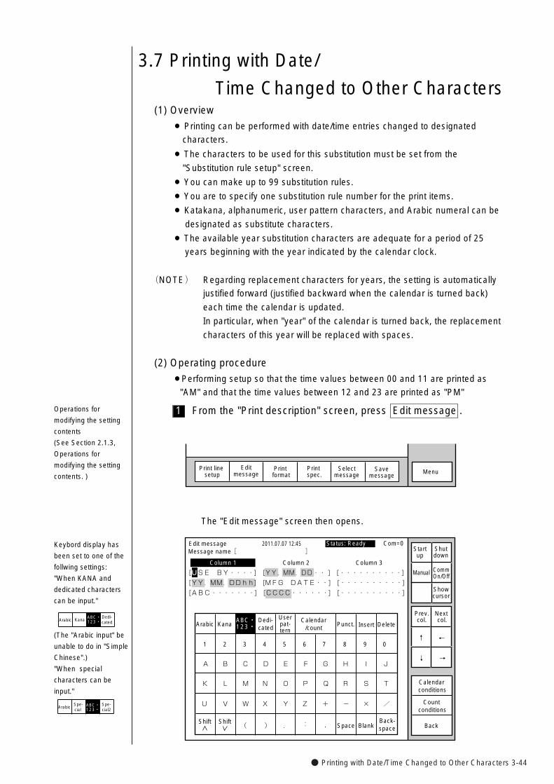
● Printing with Date/Time Changed to Other Characters 3-44
KanaArabicDedi-cated
Userpat-tern
Calendar/count
Punct. Insert Delete
K
U
A
L
V
B
M
W
C
N
X
D
O
Y
E
P
Z
F
Q
+
G
R
-
H
S
×
I
T
/
J
Space BlankBack-space( ) . : ,
Edit message
Column 1 Column 2 Column 3
[USE BY・・・・] [YY.MM.DD・・ ] [・・・・・・・・・・]�
[YY.MM.DDhh] [MFG DATE・・] [・・・・・・・・・・] �
[ABC・・・・・・・] [CCCC・・・・・・] [・・・・・・・・・・]�
�
2011.07.07 12:45
Back
Calendar conditions
Count conditions
1 2 3 4 5 6 7 8 9 0
ABC・123・�
Manual
Showcursor
Prev.col.
Next col.
↓
↑
→
←
Status: Ready Com=0 Message name[ ] Start
upShutdown
CommOn/Off
Shift Shift
The "Edit message" screen then opens.
1
(2) Operating procedure
¡Performing setup so that the time values between 00 and 11 are printed as
"AM" and that the time values between 12 and 23 are printed as "PM"
From the "Print description" screen, press Edit message .
MenuSelectmessage
Print line setup
Editmessage
Print format
Print spec.
Savemessage
3.7 Printing with Date/
Time Changed to Other Characters(1) Overview
¡ Printing can be performed with date/time entries changed to designated
characters.
¡ The characters to be used for this substitution must be set from the
"Substitution rule setup" screen.
¡ You can make up to 99 substitution rules.
¡ You are to specify one substitution rule number for the print items.
¡ Katakana, alphanumeric, user pattern characters, and Arabic numeral can be
designated as substitute characters.
¡ The available year substitution characters are adequate for a period of 25
years beginning with the year indicated by the calendar clock.
(NOTE) Regarding replacement characters for years, the setting is automatically
justified forward (justified backward when the calendar is turned back)
each time the calendar is updated.
In particular, when "year" of the calendar is turned back, the replacement
characters of this year will be replaced with spaces.
Operations for
modifying the setting
contents
(See Section 2.1.3,
Operations for
modifying the setting
contents. )
Keybord display has
been set to one of the
follwing settings:
"When KANA and
dedicated characters
can be input."
KanaDedi-cated
ABC・123・�Arabic
(The "Arabic input" be
unable to do in "Simple
Chinese".)
"When special
characters can be
input."
Spe-cial
Spe-cial2
ABC・123・�Arabic
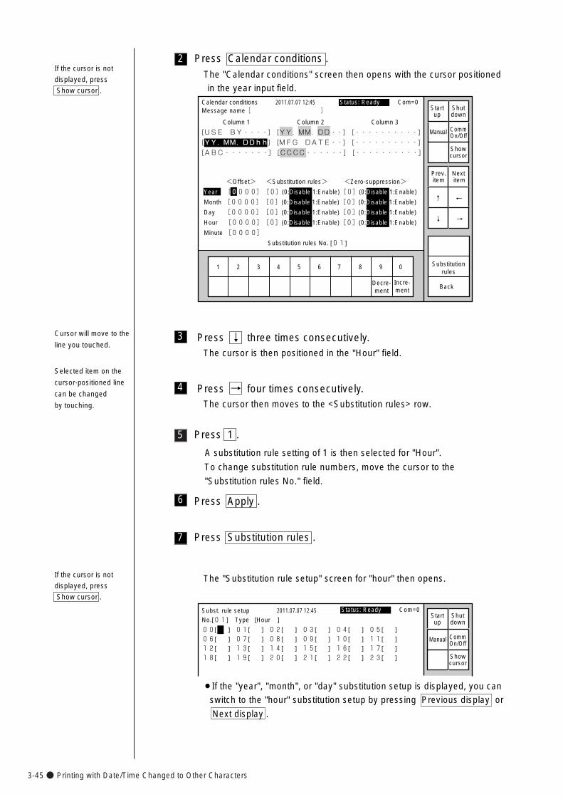
3-45● Printing with Date/Time Changed to Other Characters
5
4
3 Press ↓ three times consecutively.The cursor is then positioned in the "Hour" field.
Press → four times consecutively.The cursor then moves to the <Substitution rules> row.
Press 1 .
A substitution rule setting of 1 is then selected for "Hour".
To change substitution rule numbers, move the cursor to the
"Substitution rules No." field.
6 Press Apply .
The "Substitution rule setup" screen for "hour" then opens.
00[ ] 01[ ] 02[ ] 03[ ] 04[ ] 05[ ]
06[ ] 07[ ] 08[ ] 09[ ] 10[ ] 11[ ]
12[ ] 13[ ] 14[ ] 15[ ] 16[ ] 17[ ]
18[ ] 19[ ] 20[ ] 21[ ] 22[ ] 23[ ]
Subst. rule setup 2011.07.07 12:45
No.[01] Type [Hour ]
Manual
Showcursor
Status: Ready Com=0 Startup
Shutdown
CommOn/Off
¡If the "year", "month", or "day" substitution setup is displayed, you can
switch to the "hour" substitution setup by pressing Previous display or
Next display .
If the cursor is not
displayed, press
Show cursor .
7 Press Substitution rules .
2 Press Calendar conditions .
The "Calendar conditions" screen then opens with the cursor positioned
in the year input field.
1 2 3 4 5 6 7 8 9 0
Incre-ment
Decre-ment
Calendar conditions
Column 1 Column 2 Column 3
[USE BY・・・・] [YY.MM.DD・・] [・・・・・・・・・・] �
[YY.MM.DDhh] [MFG DATE・・] [・・・・・・・・・・] �
[ABC・・・・・・・] [CCCC・・・・・・] [・・・・・・・・・・]
2011.07.07 12:45
Back
<Offset> <Substitution rules> <Zero-suppression>
Year [0000][0](0:Disable 1:Enable)[0](0:Disable 1:Enable)
Month [0000][0](0:Disable 1:Enable)[0](0:Disable 1:Enable)
Day [0000][0](0:Disable 1:Enable)[0](0:Disable 1:Enable)
Hour [0000][0](0:Disable 1:Enable)[0](0:Disable 1:Enable)
Minute [0000]�
Substitution rules No. [01]
Manual
Showcursor
Prev.item
Next item
↓
↑
→
←
Status: Ready Com=0
Substitutionrules
Message name[ ] Startup
Shutdown
CommOn/Off
If the cursor is not
displayed, press
Show cursor .
Cursor will move to the
line you touched.
Selected item on the
cursor-positioned line
can be changed
by touching.
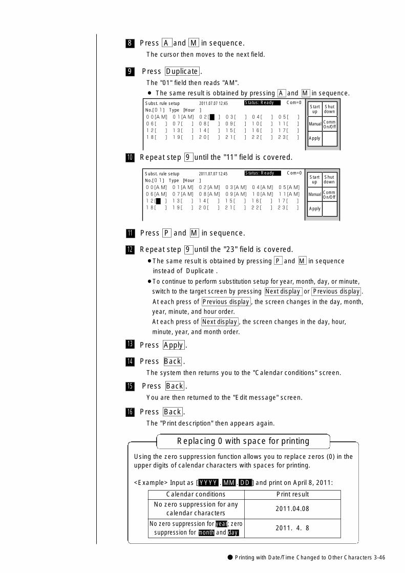
● Printing with Date/Time Changed to Other Characters 3-46
16
15
14
12 Repeat step 9 until the "23" field is covered.
¡The same result is obtained by pressing P and M in sequence
instead of Duplicate .
¡To continue to perform substitution setup for year, month, day, or minute,
switch to the target screen by pressing Next display or Previous display .
At each press of Previous display , the screen changes in the day, month,
year, minute, and hour order.
At each press of Next display , the screen changes in the day, hour,
minute, year, and month order.
Press Back .
The system then returns you to the "Calendar conditions" screen.
Press Back .
You are then returned to the "Edit message" screen.
Press Back .
The "Print description" then appears again.
13 Press Apply .
11
10
9
8
Press Duplicate .
The "01" field then reads "AM".
¡ The same result is obtained by pressing A and M in sequence.
00[A M] 01[A M] 02[ ] 03[ ] 04[ ] 05[ ] �06[ ] 07[ ] 08[ ] 09[ ] 10[ ] 11[ ]�12[ ] 13[ ] 14[ ] 15[ ] 16[ ] 17[ ] �18[ ] 19[ ] 20[ ] 21[ ] 22[ ] 23[ ]
Subst. rule setup 2011.07.07 12:45
No.[01] Type [Hour ]
Manual
Apply
Status: Ready Com=0 Startup
Shutdown
CommOn/Off
Press A and M in sequence.
The cursor then moves to the next field.
Repeat step 9 until the "11" field is covered.
00[A M] 01[A M] 02[A M] 03[A M] 04[A M] 05[A M] �06[A M] 07[A M] 08[A M] 09[A M] 10[A M] 11[A M]�12[ ] 13[ ] 14[ ] 15[ ] 16[ ] 17[ ] �18[ ] 19[ ] 20[ ] 21[ ] 22[ ] 23[ ]
Subst. rule setup 2011.07.07 12:45
No.[01] Type [Hour ]
Manual
Apply
Status: Ready Com=0Startup
Shutdown
CommOn/Off
Press P and M in sequence.
Replacing 0 with space for printing
Calendar conditions Print result
No zero suppression for anycalendar characters
2011.04.08
2011. 4. 8No zero suppression for year; zero
suppression for month and day
Using the zero suppression function allows you to replace zeros (0) in theupper digits of calendar characters with spaces for printing.
<Example> Input as [ YYYY . MM . DD ] and print on April 8, 2011:
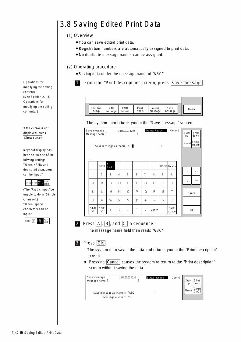
3-47● Saving Edited Print Data
3
2
1
3.8 Saving Edited Print Data(1) Overview
¡You can save edited print data.
¡Registration numbers are automatically assigned to print data.
¡No duplicate message names can be assigned.
(2) Operating procedure
¡Saving data under the message name of "ABC"
From the "Print description" screen, press Save message .
Selectmessage
Print line setup
Editmessage
Print format
Print spec.
MenuSavemessage
Kana Insert Delete
K
U
A
L
V
B
M
W
C
N
X
D
O
Y
E
P
Z
F
Q
+
G
R
-
H
S
×
I
T
/
J
SpaceBack-space( ) . : ,
Save message 2011.07.07 12:45
Cancel
1 2 3 4 5 6 7 8 9 0
ABC・123・�
OK
Save message as (name) :[ ]Manual
↓
↑
→
←
Status: Ready Com=0 Message name[ ] Start
upShutdown
CommOn/Off
Shift Shift
The system then returns you to the "Save message" screen.
Press A , B , and C in sequence.
The message name field then reads "ABC".
Save message 2011.07.07 12:45
Save message as (name) :[ABC ]�
Message number : 01
Manual
Status: Ready Com=0Message name[ ] Start
upShutdown
CommOn/Off
Press OK .
The system then saves the data and returns you to the "Print description"
screen.
¡ Pressing Cancel causes the system to return to the "Print description"
screen without saving the data.
If the cursor is not
displayed, press
Show cursor .
Operations for
modifying the setting
contents
(See Section 2.1.3,
Operations for
modifying the setting
contents. )
Keybord display has
been set to one of the
follwing settings:
"When KANA and
dedicated characters
can be input."
KanaDedi-cated
ABC・123・�Arabic
(The "Arabic input" be
unable to do in "Simple
Chinese".)
"When special
characters can be
input."
Spe-cial
Spe-cial2
ABC・123・�Arabic
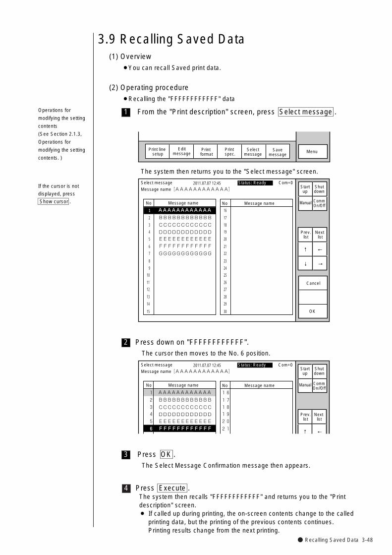
● Recalling Saved Data 3-48
4
3
2
1
3.9 Recalling Saved Data(1) Overview
¡You can recall Saved print data.
(2) Operating procedure
¡Recalling the "FFFFFFFFFFFF" data
From the "Print description" screen, press Select message .
MenuSelectmessage
Print line setup
Editmessage
Print format
Print spec.
Savemessage
No Message name
AAAAAAAAAAAA�
No Message name
1
2
3
4
5
6
7
8
9
10
11
12
13
14
15
Select message 2011.07.07 12:45
OK
16
17
18
19
20
21
22
23
24
25
26
27
28
29
30
BBBBBBBBBBBB
CCCCCCCCCCCC
DDDDDDDDDDDD
EEEEEEEEEEEE
FFFFFFFFFFFF
GGGGGGGGGGGG
Cancel
Message name[AAAAAAAAAAAA]
Manual
Prev.list
Next list
↓
↑
→
←
Status: Ready Com=0Startup
Shutdown
CommOn/Off
The system then returns you to the "Select message" screen.
Press down on "FFFFFFFFFFFF".
The cursor then moves to the No. 6 position.
Press OK .
The Select Message Confirmation message then appears.
1�AAAAAAAAAAAA�
2�
3�
4�
5�
6�
16�
17�
18�
19�
20�
21�
BBBBBBBBBBBB�
CCCCCCCCCCCC�
DDDDDDDDDDDD�
EEEEEEEEEEEE�
FFFFFFFFFFFF�
No Message name No Message name
Select message 2011.07.07 12:45Message name[AAAAAAAAAAAA]
Manual
Prev.list
Next list
↑ ←
Status: Ready Com=0 Startup
Shutdown
CommOn//Off
Press Execute .The system then recalls "FFFFFFFFFFFF" and returns you to the "Printdescription" screen.¡ If called up during printing, the on-screen contents change to the called
printing data, but the printing of the previous contents continues. Printing results change from the next printing.
If the cursor is not
displayed, press
Show cursor .
Operations for
modifying the setting
contents
(See Section 2.1.3,
Operations for
modifying the setting
contents. )
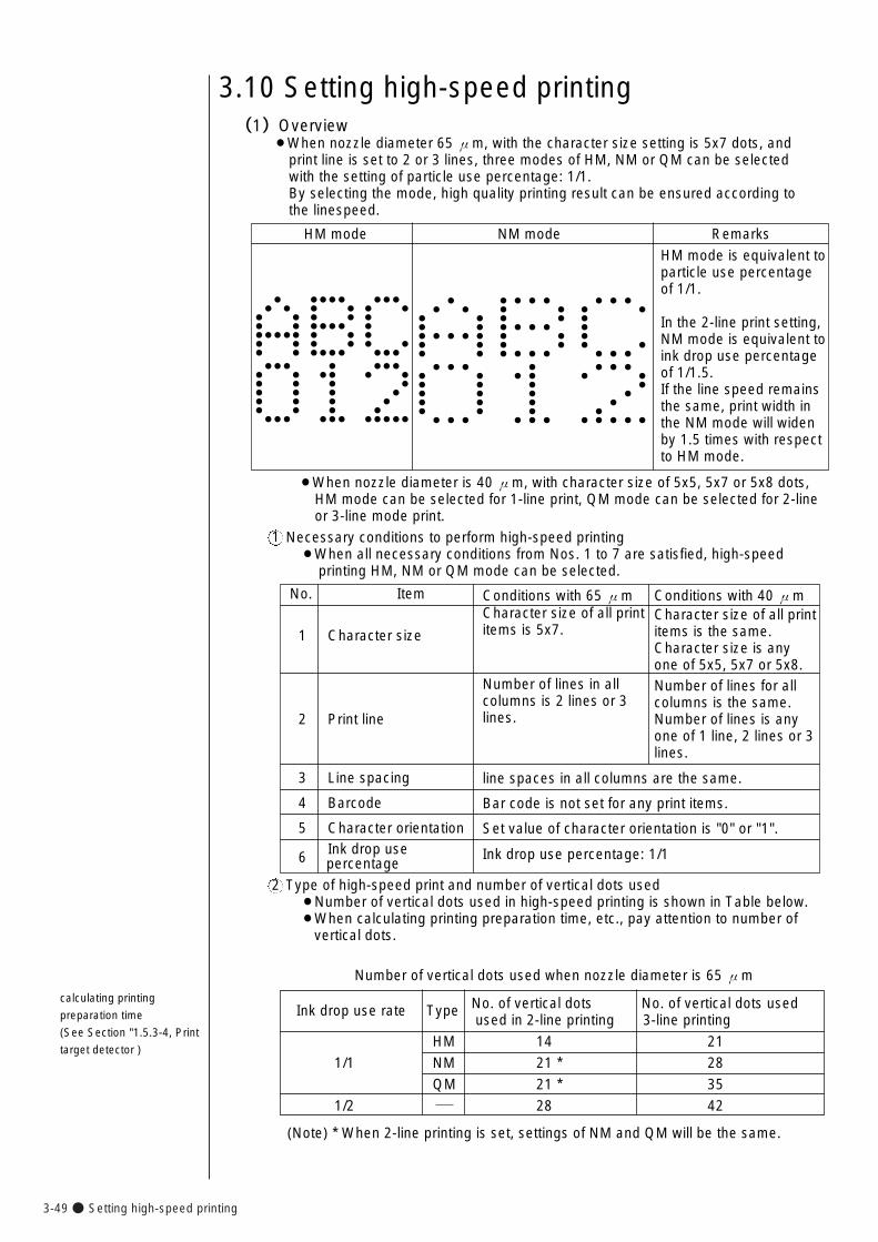
3-49● Setting high-speed printing
(1)Overview¡When nozzle diameter 65 μm, with the character size setting is 5x7 dots, and
print line is set to 2 or 3 lines, three modes of HM, NM or QM can be selected with the setting of particle use percentage: 1/1.By selecting the mode, high quality printing result can be ensured according to the linespeed.
3.10 Setting high-speed printing
Necessary conditions to perform high-speed printing¡When all necessary conditions from Nos. 1 to 7 are satisfied, high-speed
printing HM, NM or QM mode can be selected.
1
Type of high-speed print and number of vertical dots used¡Number of vertical dots used in high-speed printing is shown in Table below.¡When calculating printing preparation time, etc., pay attention to number of
vertical dots.
2
calculating printing
preparation time
(See Section "1.5.3-4, Print
target detector )
HM mode NM mode Remarks
HM mode is equivalent toparticle use percentageof 1/1.
In the 2-line print setting,NM mode is equivalent to ink drop use percentageof 1/1.5.If the line speed remainsthe same, print width inthe NM mode will widenby 1.5 times with respectto HM mode.
Ink drop use rate Type No. of vertical dots No. of vertical dots used used in 2-line printing 3-line printing
HM 14 21
1/1 NM 21 * 28
QM 21 * 35
1/2 28 42
(Note) * When 2-line printing is set, settings of NM and QM will be the same.
¡When nozzle diameter is 40 μm, with character size of 5x5, 5x7 or 5x8 dots,HM mode can be selected for 1-line print, QM mode can be selected for 2-line or 3-line mode print.
Conditions with 65 μmCharacter size of all printitems is 5x7.
Number of lines in allcolumns is 2 lines or 3lines.
line spaces in all columns are the same.
Bar code is not set for any print items.
Set value of character orientation is "0" or "1".
Ink drop use percentage: 1/1
Conditions with 40 μmCharacter size of all printitems is the same.Character size is anyone of 5x5, 5x7 or 5x8.Number of lines for allcolumns is the same.Number of lines is anyone of 1 line, 2 lines or 3 lines.
No. Item
1 Character size
2 Print line
3 Line spacing
4 Barcode
5 Character orientation
6 Ink drop use percentage
Number of vertical dots used when nozzle diameter is 65 μm
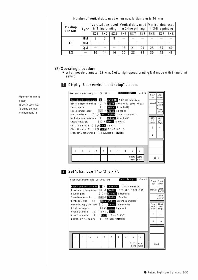
● Setting high-speed printing 3-50
1
(2) Operating procedure¡ When nozzle diameter 65 μm, Set to high-speed printing NM mode with 3-line print
setting.
Display "User environment setup" screen.
1 2 3 4 5 6 7 8 9 0
User environment setup
Repeat print sensor mode [1](1: signal ON 2: ON-Off trransition)
Reverse direction printing [0](0: Disable 1: OFF=ABC 2: OFF=CBA)
Reverse print [1](1: method1 2: method2)
Speed compensation [0](0: Disable 1: Enable)
Print signal type [1](1: print. complete 2: print.-in-progress)
Method to apply print data [1](1: method1 2: method2)
Create messages [0](0: access 1: protect)
2011.07.07 12:45
BackIncre-ment
Decre-ment
Manual
Showcursor
Status: Ready Com=0 Startup
Shutdown
CommOn/Off
Prev.set-tings
Nextset-tings
↑
↓
Char. Size menu 1 [1](1: 5×8 2: 5×7)
Char. Size menu 2 [1](1: 7×10 2: 9×8 3: 9×7)
Excitation V-ref. warning [1](0:Disable 1:Enable)
→
←
User environment
setup
(See Section 4.2,
"Setting the user
environment " )
2 Set "Char. size 1" to "2: 5 x 7".
1 2 3 4 5 6 7 8 9 0
User environment setup 2011.07.07 12:45
BackIncre-ment
Decre-ment
Manual
Showcursor
Status: Ready Com=0 Startup
Shutdown
CommOn/Off
Prev.set-tings
Nextset-tings
↑
↓ →
←
Repeat print sensor mode [1](1: signal ON 2: ON-Off trransition)
Reverse direction printing [0](0: Disable 1: OFF=ABC 2: OFF=CBA)
Reverse print [1](1: method1 2: method2)
Speed compensation [0](0: Disable 1: Enable)
Print signal type [1](1: print. complete 2: print.-in-progress)
Method to apply print data [1](1: method1 2: method2)
Create messages [0](0: access 1: protect)
Char. Size menu 1 [2](1: 5×8 2: 5×7)
Char. Size menu 2 [1](1: 7×10 2: 9×8 3: 9×7)
Excitation V-ref. warning [1](0:Disable 1:Enable)
5X55--10
Ink drop use rate
1/1
1/2
Type
HMNMQM-
Vertical dots usedin 1-line printing
Vertical dots usedin 2-line printing
Vertical dots usedin 3-line printing
5X77--14
5X88--16
5X5--1520
5X7--2128
5X8--2432
5X5--2530
5X7--3542
5X8--4048
Number of vertical dots used when nozzle diameter is 40 μm
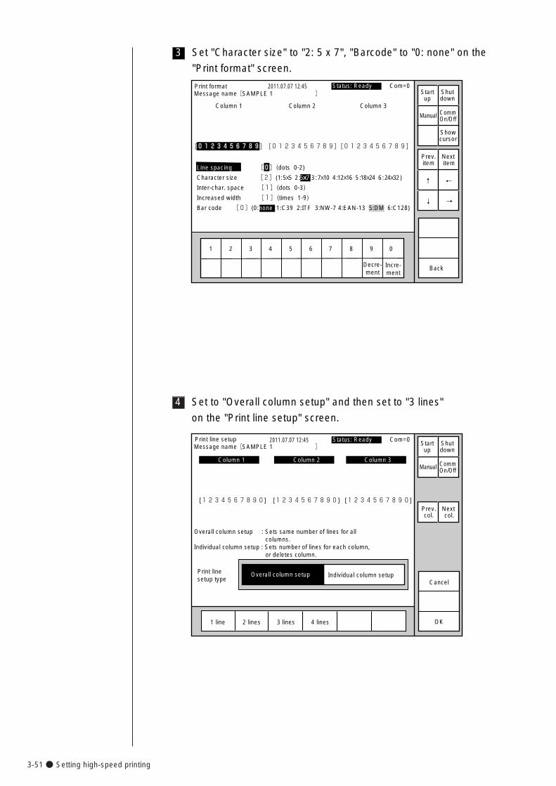
3-51● Setting high-speed printing
4 Set to "Overall column setup" and then set to "3 lines"
on the "Print line setup" screen.
Print linesetup type
Print line setup 2011.07.07 12:45
OK1 line 2 lines 3 lines 4 lines
Individual column setupOverall column setupCancel
Overall column setup : Sets same number of lines for all columns.Individual column setup : Sets number of lines for each column, or deletes column.
Column 1 Column 2 Column 3
[1234567890] [1234567890] [1234567890]
Status: Ready Com=0
Prev.col.
Next col.
Message name[SAMPLE 1 ]
Manual
Startup
Shutdown
CommOn/Off
3 Set "Character size" to "2: 5 x 7", "Barcode" to "0: none" on the
"Print format" screen.
1 2 3 4 5 6 7 8 9 0
Incre-ment
Decre-ment
Print format 2011.07.07 12:45
Back
Column 1 Column 2 Column 3
�
�
�
[0123456789] [0123456789] [0123456789] �
Line spacing [0](dots 0-2)
Character size [2](1: 5x5 2 :5x7 3 : 7x10 4 :12x16 5 :18x24 6 : 24x32 )
Inter-char. space [1](dots 0-3)
Increased width [1](times 1-9)
Bar code [0](0:none 1:C39 2:ITF 3:NW-7 4:EAN-13 5:DM 6:C128)
Manual
Showcursor
Prev.item
Next item
↓
↑
Status: Ready Com=0 Message name[SAMPLE 1 ] Start
upShutdown
CommOn/Off
→
←
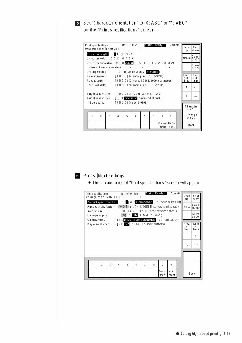
● Setting high-speed printing 3-52
5 Set "Character orientation" to "0: ABC" or "1: ABC"
on the "Print specifications" screen.
Print specifications 2011.07.07 12:45
Character height [50] (0-99)
Character width [002] (0-199)
Character orientation [0] (0:ABC 1:ABC 2: 3: )
(Arrow: Printing direction) → ← ← →
Printing method 2 (1: single scan 2: Interlaced )
Repeat intervals [0000] (scanning unit SC 0-9999)
Repeat count [0000] (0: none, 1-9998, 9999: continuous)
Print start delay [0050] (scanning unit SC 0-1234)
Target sensor timer [000] (1/10 sec 0: none, 1-999)
Target sensor filter [1] (1: time setup 2:until end of print. )
Setup value [0050] (msec 0-9999)
Back
1 2 3 4 5 6 7 8 9 0
Incre-ment
Decre-ment
Characterunit CH
Scanning unit SC
ABC ABC
Manual
Showcursor
Status: Ready Com=0 Message name[SAMPLE 1 ] Start
upShutdown
CommOn/Off
Prev.set-tings
Nextset-tings
↑
↓ →�
←�
6 Press Next settings .
¡ The second page of "Print specifications" screen will appear.
Print specifications 2011.07.07 12:45
Back
1 2 3 4 5 6 7 8 9 0
Incre-ment
Decre-ment
Manual
Showcursor
Status: Ready Com=0 Message name[SAMPLE 1 ] Start
upShutdown
CommOn/Off
Prev.set-tings
Nextset-tings
↑
↓
Product speed matching [0] (0 : Time-based 1 : Encoder based)�
Pulse rate div. Factor [001] (1/1~1/999 Enter denominator. )
Ink drop use [03] (1/1~1/16 Enter denominator. )
High-speed print [0] (0: HM 1: NM 2:QM )�
Calendar offset [1] (1: offset from yesterday 2: from today)�
Day of week char. [1] (1: 1-7 2: A-G 3: User pattern)
→
←
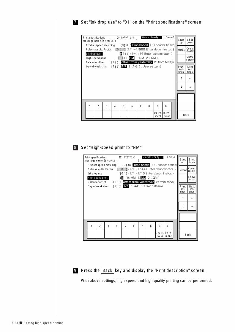
3-53● Setting high-speed printing
8 Set "High-speed print" to "NM".
9 Press the Back key and display the "Print description" screen.
With above settings, high speed and high quality printing can be performed.
Print specifications 2011.07.07 12:45
Back
1 2 3 4 5 6 7 8 9 0
Incre-ment
Decre-ment
Manual
Showcursor
Status: Ready Com=0 Message name[SAMPLE 1 ] Start
upShutdown
CommOn/Off
Prev.set-tings
Nextset-tings
↑
↓
Product speed matching [0] (0 : Time-based 1 : Encoder based)�
Pulse rate div. Factor [001] (1/1~1/999 Enter denominator. )
Ink drop use [01] (1/1~1/16 Enter denominator. )
High-speed print [1] (0: HM 1: NM 2:QM )�
Calendar offset [1] (1: offset from yesterday 2: from today)�
Day of week char. [1] (1: 1-7 2: A-G 3: User pattern)
→
←
7 Set "Ink drop use" to "01" on the "Print specifications" screen.
Print specifications 2011.07.07 12:45
Back
1 2 3 4 5 6 7 8 9 0
Incre-ment
Decre-ment
Manual
Showcursor
Status: Ready Com=0 Message name[SAMPLE 1 ] Start
upShutdown
CommOn/Off
Prev.set-tings
Nextset-tings
↑
↓ →�
←�
Product speed matching [0] (0 : Time-based 1 : Encoder based)�
Pulse rate div. Factor [001] (1/1~1/999 Enter denominator. )
Ink drop use [01] (1/1~1/16 Enter denominator. )
High-speed print [0] (0: HM 1: NM 2:QM )�
Calendar offset [1] (1: offset from yesterday 2: from today)�
Day of week char. [1] (1: 1-7 2: A-G 3: User pattern)
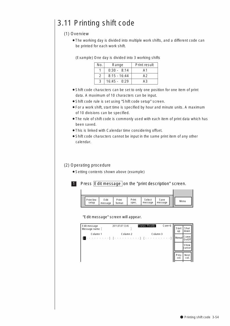
● Printing shift code 3-54
No. Range Print result1 0:30 - 8:14 A12 8:15 - 16:44 A23 16:45 - 0:29 A3
3.11 Printing shift code(1) Overview
¡The working day is divided into multiple work shifts, and a different code can
be printed for each work shift.
(Example) One day is divided into 3 working shifts
¡Shift code characters can be set to only one position for one item of print
data. A maximum of 10 characters can be input.
¡Shift code rule is set using "Shift code setup" screen.
¡For a work shift, start time is specified by hour and minute units. A maximum
of 10 divisions can be specified.
¡The rule of shift code is commonly used with each item of print data which has
been saved.
¡This is linked with Calendar time considering offset.
¡Shift code characters cannot be input in the same print item of any other
calendar.
(2) Operating procedure
¡Setting contents shown above (example)
1 Press Edit message on the "print description" screen.
Selectmessage
Print line setup
Editmessage
Print format
Print spec. MenuSave
message
Edit message 2011.07.07 12:45
Column 1 Column 2 Column 3
[・・・・・・・・・・] [・・・・・・・・・・] [・・・・・・・・・・] �
�
Manual
Showcursor
Prev.col.
Next col.
Status: Ready Com=0 Message name[ ] Start
upShutdown
CommOn/Off
"Edit message" screen will appear.
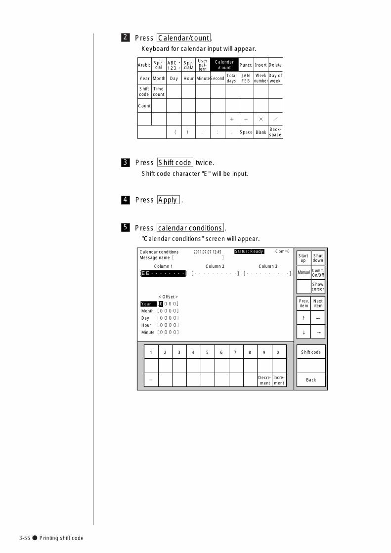
3-55● Printing shift code
2 Press Calendar/count .Keyboard for calendar input will appear.
TotaldaysYear Month
Shiftcode
Timecount
Day Hour Minute
Count
Calendar/count
Spe-cialArabic Spe-
cial2Userpat-tern
Punct. Insert Delete
Space BlankBack-space
ABC・123・�
SecondJANFEB
+� -� � /�
(� )� .� :� ,�
Weeknumber
Day ofweek
3 Press Shift code twice.
Shift code character "E" will be input.
4 Press Apply .
5 Press calendar conditions ."Calendar conditions" screen will appear.
1 2 3 4 5 6 7 8 9 0
Incre-ment
Decre-ment
Calendar conditions
Column 1 Column 2 Column 3
[EE・・・・・・・・] [・・・・・・・・・・] [・・・・・・・・・・] �
�
2011.07.07 12:45
Back
< Offset >
Year [0000]�
Month [0000]�
Day [0000]�
Hour [0000]�
Minute[0000] �
-�
Manual
Showcorsor
Prev.item
Next item
↓
↑
→
←
Status: Ready Com=0 Message name[ ] Start
upShutdown
CommOn/Off
Shift code
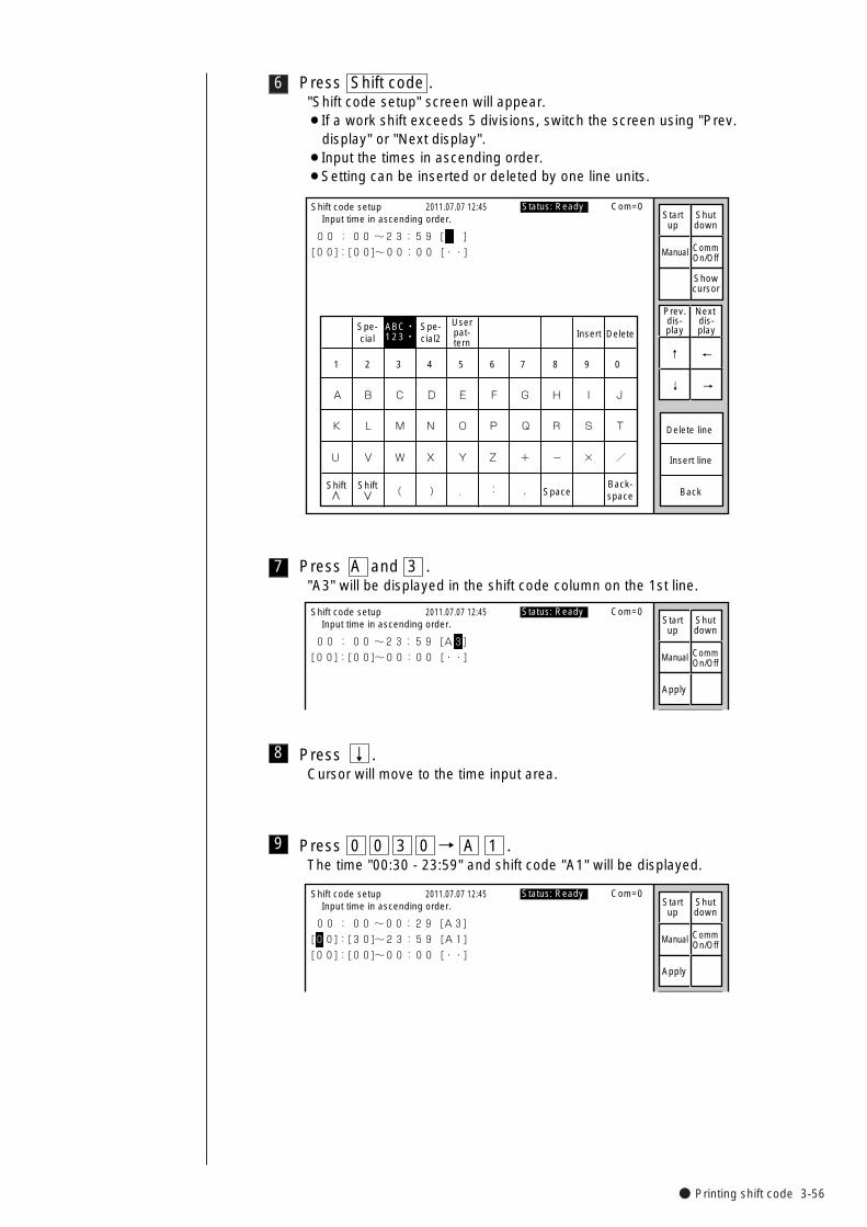
● Printing shift code 3-56
6 Press Shift code ."Shift code setup" screen will appear.¡If a work shift exceeds 5 divisions, switch the screen using "Prev.
display" or "Next display".¡Input the times in ascending order.¡Setting can be inserted or deleted by one line units.
Spe-cial
Spe-cial2
Userpat-tern
Insert Delete
K
U
A
L
V
B
M
W
C
N
X
D
O
Y
E
P
Z
F
Q
+
G
R
-
H
S
×
I
T
/
J
SpaceBack-space( ) . : ,
Shift code setup
00 : 00 ~23:59 [ ]�
[00]:[00]~00:00 [・・]
2011.07.07 12:45
Back
Delete line
Insert line
1 2 3 4 5 6 7 8 9 0
ABC・123・�
Manual
Showcursor
Prev.dis-play
Next dis-play
↓
↑
→
←
Status: Ready Com=0 Input time in ascending order. Start
upShutdown
CommOn/Off
Shift Shift
7 Press A and 3 ."A3" will be displayed in the shift code column on the 1st line.
Shift code setup
00 : 00 ~23:59 [A3]�
[00]:[00]~00:00 [・・]
2011.07.07 12:45
Manual
Apply
Status: Ready Com=0 Input time in ascending order. Start
upShutdown
CommOn/Off
8 Press ↓ .Cursor will move to the time input area.
9 Press 0 0 3 0 → A 1 .The time "00:30 - 23:59" and shift code "A1" will be displayed.
Shift code setup
00 : 00 ~00:29 [A3]�
[00]:[30]~23:59 [A1]�
[00]:[00]~00:00 [・・]
2011.07.07 12:45
Manual
Apply
Status: Ready Com=0 Input time in ascending order. Start
upShutdown
CommOn/Off
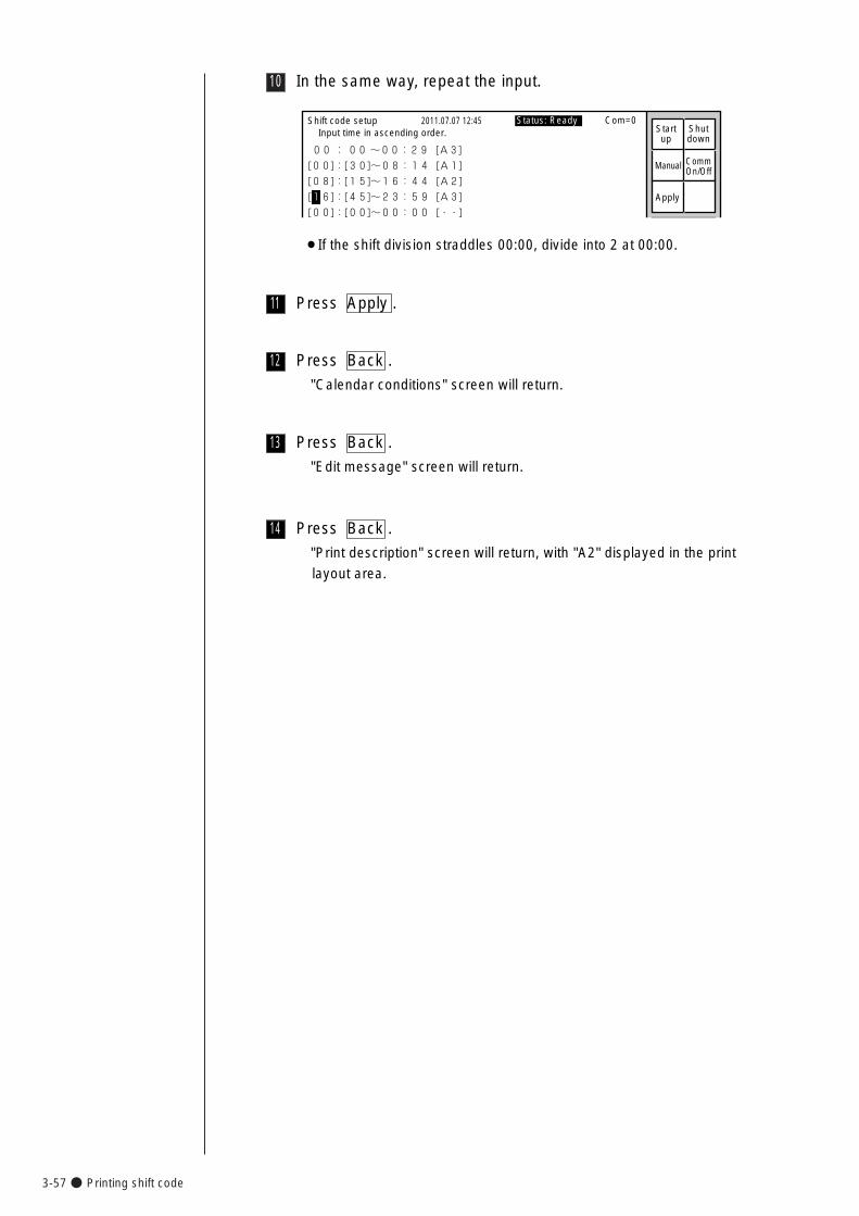
3-57● Printing shift code
10 In the same way, repeat the input.
Shift code setup
00 : 00 ~00:29 [A3]�
[00]:[30]~08:14 [A1]�
[08]:[15]~16:44 [A2]�
[16]:[45]~23:59 [A3]�
[00]:[00]~00:00 [・・]
2011.07.07 12:45
Manual
Apply
Status: Ready Com=0 Input time in ascending order. Start
upShutdown
CommOn/Off
¡If the shift division straddles 00:00, divide into 2 at 00:00.
11 Press Apply .
12 Press Back .
"Calendar conditions" screen will return.
13 Press Back .
"Edit message" screen will return.
14 Press Back .
"Print description" screen will return, with "A2" displayed in the print
layout area.
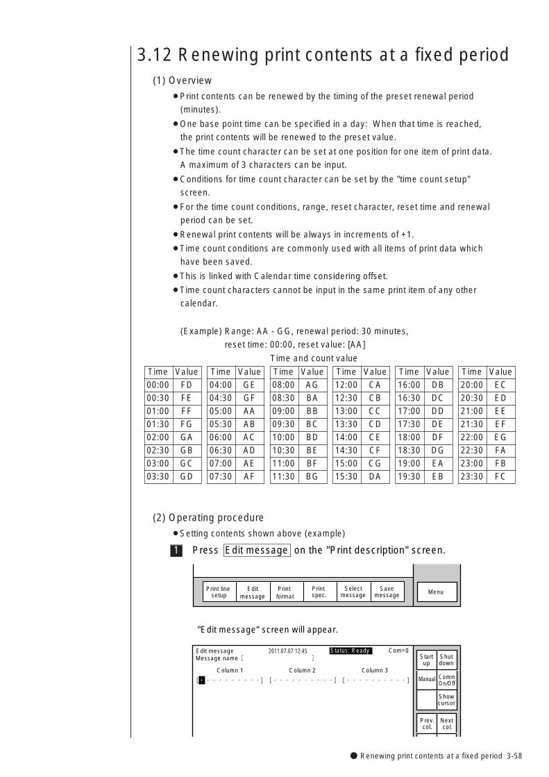
● Renewing print contents at a fixed period 3-58
3.12 Renewing print contents at a fixed period(1) Overview
¡Print contents can be renewed by the timing of the preset renewal period
(minutes).
¡One base point time can be specified in a day: When that time is reached,
the print contents will be renewed to the preset value.
¡The time count character can be set at one position for one item of print data.
A maximum of 3 characters can be input.
¡Conditions for time count character can be set by the "time count setup"
screen.
¡For the time count conditions, range, reset character, reset time and renewal
period can be set.
¡Renewal print contents will be always in increments of +1.
¡Time count conditions are commonly used with all items of print data which
have been saved.
¡This is linked with Calendar time considering offset.
¡Time count characters cannot be input in the same print item of any other
calendar.
(Example) Range: AA - GG, renewal period: 30 minutes,
reset time: 00:00, reset value: [AA]
Time and count value
Time Value 00:00 FD00:30 FE01:00 FF01:30 FG02:00 GA02:30 GB03:00 GC03:30 GD
Time Value 04:00 GE04:30 GF05:00 AA05:30 AB06:00 AC06:30 AD07:00 AE07:30 AF
Time Value 08:00 AG08:30 BA09:00 BB09:30 BC10:00 BD10:30 BE11:00 BF11:30 BG
Time Value 12:00 CA12:30 CB13:00 CC13:30 CD14:00 CE14:30 CF15:00 CG15:30 DA
Time Value 16:00 DB16:30 DC17:00 DD17:30 DE18:00 DF18:30 DG19:00 EA19:30 EB
Time Value 20:00 EC20:30 ED21:00 EE21:30 EF22:00 EG22:30 FA23:00 FB23:30 FC
(2) Operating procedure
¡Setting contents shown above (example)
1 Press Edit message on the "Print description" screen.
Selectmessage
Print line setup
Editmessage
Print format
Print spec. MenuSave
message
Edit message 2011.07.07 12:45
Column 1 Column 2 Column 3
[・・・・・・・・・・] [・・・・・・・・・・] [・・・・・・・・・・] �
�
Manual
Showcursor
Prev.col.
Next col.
Status: Ready Com=0 Message name[ ] Start
upShutdown
CommOn/Off
"Edit message" screen will appear.
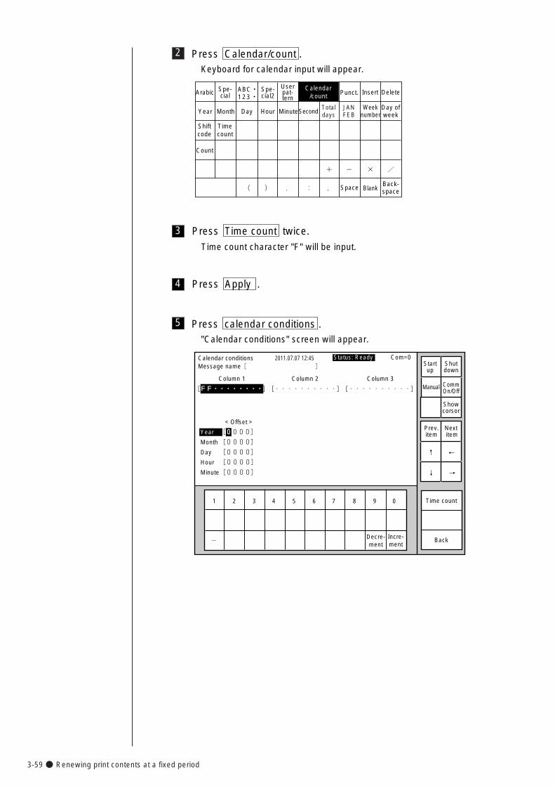
3-59● Renewing print contents at a fixed period
2 Press Calendar/count .Keyboard for calendar input will appear.
TotaldaysYear Month
Shiftcode
Timecount
Day Hour Minute
Count
Calendar/count
Spe-cialArabic Spe-
cial2Userpat-tern
Punct. Insert Delete
Space BlankBack-space
ABC・123・�
SecondJANFEB
+� -� � /�
(� )� .� :� ,�
Weeknumber
Day ofweek
3 Press Time count twice.
Time count character "F" will be input.
4 Press Apply .
5 Press calendar conditions ."Calendar conditions" screen will appear.
1 2 3 4 5 6 7 8 9 0
Incre-ment
Decre-ment
Calendar conditions
Column 1 Column 2 Column 3
[FF・・・・・・・・] [・・・・・・・・・・] [・・・・・・・・・・] �
�
2011.07.07 12:45
Back
< Offset >
Year [0000]�
Month [0000]�
Day [0000]�
Hour [0000]�
Minute[0000] �
-�
Manual
Showcorsor
Prev.item
Next item
↓
↑
→
←
Status: Ready Com=0 Message name[ ] Start
upShutdown
CommOn/Off
Time count
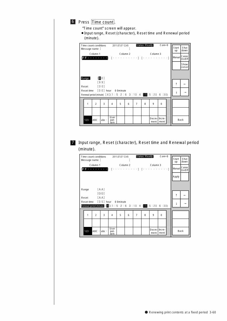
● Renewing print contents at a fixed period 3-60
6 Press Time count ."Time count" screen will appear.¡Input range, Reset (character), Reset time and Renewal period
(minute).
1 2 3 4 5 6 7 8 9 0
Incre-ment
Decre-ment
ABC・�abc・�
Time count conditions
Column 1 Column 2 Column 3
[FF・・・・・・・・] [・・・・・・・・・・] [・・・・・・・・・・] �
�
2011.07.07 12:45
Back
Range [00]�
[99]�
Reset [00]�
Reset time [00]hour 0 0minute�
Renewal period (minute)[4](1:5 2:6 3:10 4:15 5:20 6:30) �
Manual
Showcorsor
↓
↑
→
←
Status: Ready Com=0 Message name[ ] Start
upShutdown
CommOn/Off
123・�Userpat-tern
7 Input range, Reset (character), Reset time and Renewal period
(minute).
1 2 3 4 5 6 7 8 9 0
Incre-ment
Decre-ment
ABC・�abc・�
Time count conditions
Column 1 Column 2 Column 3
[FF・・・・・・・・] [・・・・・・・・・・] [・・・・・・・・・・] �
�
2011.07.07 12:45
Back
Range [AA]�
[GG]�
Reset [AA]�
Reset time [05]hour 0 0minute�
Renewal period (minute)[4](1:5 2:6 3:10 4:15 5:20 6:30) �
Manual
Apply
↓
↑
→
←
Status: Ready Com=0 Message name[ ] Start
upShutdown
CommOn/Off
123・�Userpat-tern
3-61● Renewing print contents at a fixed period
8 Press Apply .
9 Press Back .
"Calendar conditions" screen will return.
10 Press Back .
"Edit message" screen will return.
11 Press Back .
"Print description" screen will return, with "CB" displayed in the print
layout area.
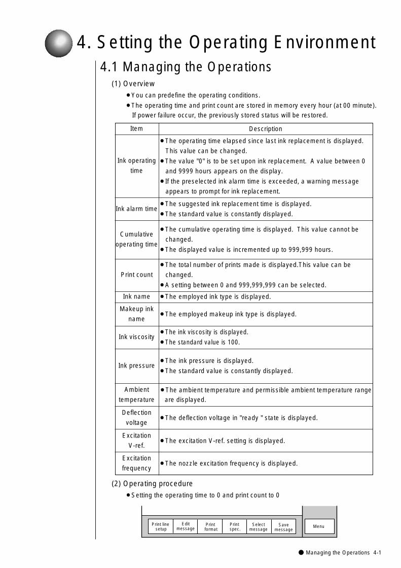
● Managing the Operations 4-1
4. Setting the Operating Environment
DescriptionItem
¡The excitation V-ref. setting is displayed.
¡The total number of prints made is displayed.This value can be
changed.
¡A setting between 0 and 999,999,999 can be selected.
Excitation
V-ref.
Deflection
voltage
¡The ink pressure is displayed.
¡The standard value is constantly displayed.Ink pressure
Ambient
temperature
Makeup ink
name
¡The suggested ink replacement time is displayed.
¡The standard value is constantly displayed.
¡The ambient temperature and permissible ambient temperature range
are displayed.
¡The deflection voltage in "ready " state is displayed.
¡The employed ink type is displayed.
¡The employed makeup ink type is displayed.
Ink viscosity¡The ink viscosity is displayed.
¡The standard value is 100.
¡The nozzle excitation frequency is displayed.Excitation
frequency
¡The cumulative operating time is displayed. This value cannot be
changed.
¡The displayed value is incremented up to 999,999 hours.
Ink name
Print count
Cumulative
operating time
Ink alarm time
Ink operating
time
¡The operating time elapsed since last ink replacement is displayed.
This value can be changed.
¡The value "0" is to be set upon ink replacement. A value between 0
and 9999 hours appears on the display.
¡If the preselected ink alarm time is exceeded, a warning message
appears to prompt for ink replacement.
4.1 Managing the Operations(1) Overview
¡You can predefine the operating conditions.
¡The operating time and print count are stored in memory every hour (at 00 minute).
If power failure occur, the previously stored status will be restored.
(2) Operating procedure
¡Setting the operating time to 0 and print count to 0
MenuSelectmessage
Print line setup
Editmessage
Print format
Print spec.
Savemessage
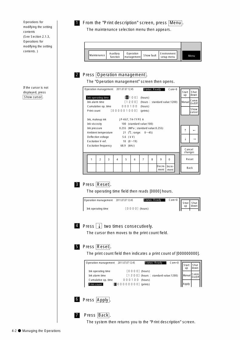
4-2● Managing the Operations
3
2 Press Operation management .
The "Operation management" screen then opens.
1 2 3 4 5 6 7 8 9 0
Operation management
Ink operating time [0100] (hours)
Ink alarm time [1200] (hours; standard value:1200)
Cumulative op. time 000100 (hours)
Print count [000001000] (prints)
Ink, makeup ink JP-K67, TH-TYPE A
Ink viscosity 100 (standard value:100)
Ink pressure 0.255 (MPa ; standard value:0.255)
Ambient temperature 21 ( C; range: 0~45)
Deflection voltage 5.6 ( k V)
Excitation V-ref. 10 (0~19)
Excitation frequency 68.9 (kHz)
2011.07.07 12:45
Cancel changes
Reset
Incre-ment
Decre-ment
Back
Manual
Showcursor
↓
↑
→
←
Status: Ready Com=0 Startup
Shutdown
CommOn/Off
Press Reset .
The operating time field then reads [0000] hours.
Operation management
Ink operating time [0000](hours)
2011.07.07 12:45 Status: Ready Com=0Stratup
Shutdown
1
MaintenanceAuxiliary function
Operationmanagement Show fault Menu
Environmentsetup menu
From the "Print description" screen, press Menu .
The maintenance selection menu then appears.
If the cursor is not
displayed, press
Show cursor .
Operations for
modifying the setting
contents
(See Section 2.1.3,
Operations for
modifying the setting
contents. )
5 Press Reset .
The print count field then indicates a print count of [000000000].
Operation management
Ink operating time [0000](hours)
Ink alarm time [1200](hours; standard value:1200)
Cumulative op. time 000100 (hours)
Print count [000000000](prints)
2011.07.07 12:45
Manual
Apply
Status: Ready Com=0 Startup
Shutdown
CommOn/Off
4 Press ↓ two times consecutively.The cursor then moves to the print count field.
7 Press Back .
The system then returns you to the "Print description" screen.
6 Press Apply .
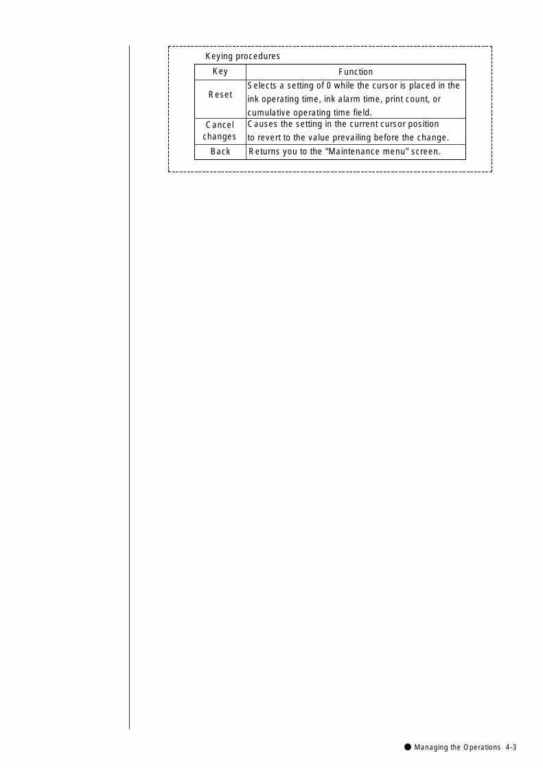
● Managing the Operations 4-3
Key Function
ResetSelects a setting of 0 while the cursor is placed in the
ink operating time, ink alarm time, print count, or
cumulative operating time field.Cancel
changes
Back
Causes the setting in the current cursor position
to revert to the value prevailing before the change.
Returns you to the "Maintenance menu" screen.
Keying procedures
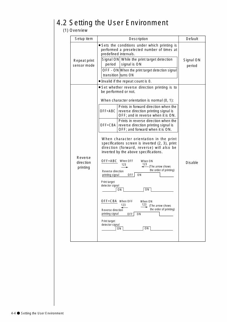
4-4● Setting the User Environment
When the print target detection signalturns ON
4.2 Setting the User Environment(1) Overview
Setup item Description
Repeat printsensor mode
Default
¡Sets the conditions under which printing isperformed a preselected number of times atpredefined intervals.
Signal ON
period
While the print target detection signal is ON
Signal ONperiod
OFF - ONtransition
¡Invalid if the repeat count is 0.
Reversedirectionprinting
Disable
¡Set whether reverse direction printing is tobe performed or not.
When character orientation is normal (0, 1):
Prints in reverse direction when the reverse direction printing signal is OFF; and forward when it is ON.
Prints in forward direction when the reverse direction printing signal is OFF; and in reverse when it is ON.
OFF=ABC
OFF=CBA
OFF=ABC
Reverse direction printing signal OFF ON
123When OFF When ON
123(The arrow shows the order of printing)
Print target detector signal
ON ON
OFF=CBA
OFF ON
123When OFF When ON
123
ON ON
(The arrow shows the order of printing)Reverse direction
printing signal
Print target detector signal
When character orientation in the printspecifications screen is inverted (2, 3), printdirection (forward, reverse) will also beinverted by the above specifications.
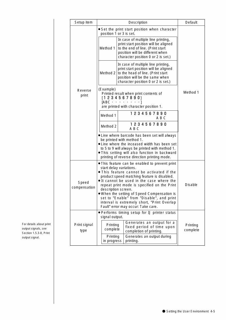
● Setting the User Environment 4-5
Setup item Description Default
Reverse print
Method 1
¡Line where barcode has been set will alwaysbe printed with method 1.
¡Line where the inceased width has been setto 5 to 9 will always be printed with method 1.
¡This setting will also function in backwardprinting of reverse direction printing mode.
Speedcompensation
Disable
¡This feature can be enabled to prevent printstart delay variations.
¡This feature cannot be activated if theproduct speed matching feature is disabled.
¡It cannot be used in the case where therepeat print mode is specified on the Printdescription screen.
¡When the setting of Speed Compensation isset to "Enable" from "Disable", and printinterval is extremely short, "Print OverlapFault" error may occur: Take care.
Print signal
typePrinting
complete
¡Performs timing setup for IJ printer statussignal output.
Generates an output for afixed period of t ime uponcompletion of printing.
Printingcomplete
Generates an output during printing.
Printing in progress
For details about print
output signals, see
Section 1.5.3-8, Print
output signal.
¡Set the print start position when characterposition 1 or 3 is set.
In case of multiple line printing,print start position will be alignedto the head of line. (Print startposition will be the same whencharacter position 0 or 2 is set.)
In case of multiple line printing,print start position will be alignedto the end of line. (Print startposition will be different whencharacter position 0 or 2 is set.)
Method 1
Method 2
(Example)Printed result when print contents of[1234567890] [ABC・・・・・・・・] are printed with character position 1.
1234567890A B C
1234567890A B C
Method 1
Method 2
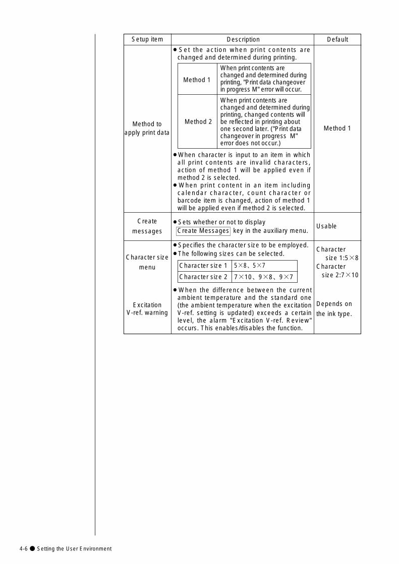
4-6● Setting the User Environment
Setup item Description Default
Method toapply print data
Method 1
¡Set the action when print contents arechanged and determined during printing.
¡When character is input to an item in whichall print contents are invalid characters,action of method 1 will be applied even ifmethod 2 is selected.
¡When print content in an item includingcalendar character, count character orbarcode item is changed, action of method 1will be applied even if method 2 is selected.
When print contents arechanged and determined duringprinting, "Print data changeoverin progress M" error will occur.
Method 1
When print contents arechanged and determined duringprinting, changed contents willbe reflected in printing aboutone second later. ("Print datachangeover in progress M"error does not occur.)
Method 2
Character size
menu
Excitation V-ref. warning
Character size 1:5×8
Character size 2:7×10
Depends on
the ink type.
¡Specifies the character size to be employed.¡The following sizes can be selected.
¡When the difference between the currentambient temperature and the standard one(the ambient temperature when the excitationV-ref. setting is updated) exceeds a certainlevel, the alarm "Excitation V-ref. Review"occurs. This enables/disables the function.
5×8、5×7Character size 1
7×10、9×8、9×7Character size 2
Create
messagesUsable
¡Sets whether or not to display Create Messages key in the auxiliary menu.
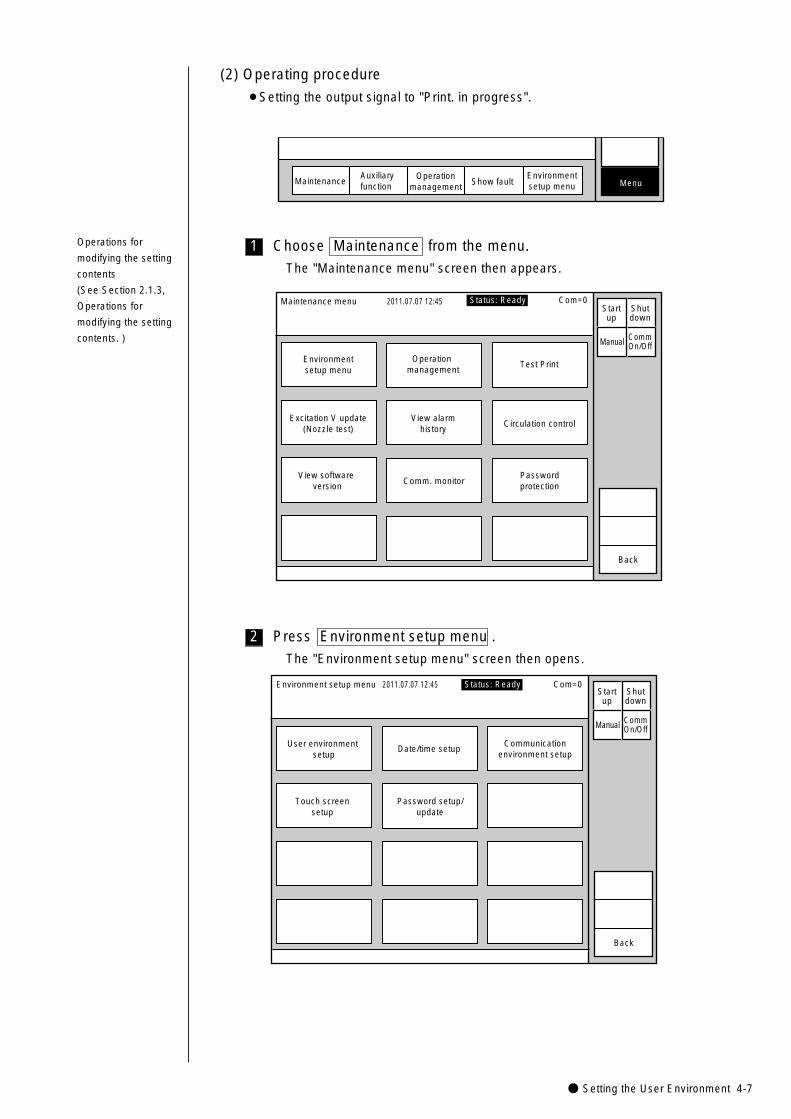
● Setting the User Environment 4-7
2 Press Environment setup menu .
The "Environment setup menu" screen then opens.
Environment setup menu 2011.07.07 12:45
User environment setup
Date/time setupCommunication
environment setup
Touch screensetup
Password setup/update
Back
Manual
Startup
Shutdown
CommOn/Off
Status: Ready Com=0
1 Choose Maintenance from the menu.
The "Maintenance menu" screen then appears.
Maintenance menu 2011.07.07 12:45
Environmentsetup menu
Operation management
Test Print
Excitation V update(Nozzle test)
View software version
View alarmhistory
Circulation control
Passwordprotection
Comm. monitor
Back
Manual
Status: Ready Com=0Startup
Shutdown
CommOn/Off
Operations for
modifying the setting
contents
(See Section 2.1.3,
Operations for
modifying the setting
contents. )
MaintenanceAuxiliary function
Operationmanagement
Show fault MenuEnvironmentsetup menu
(2) Operating procedure
¡Setting the output signal to "Print. in progress".
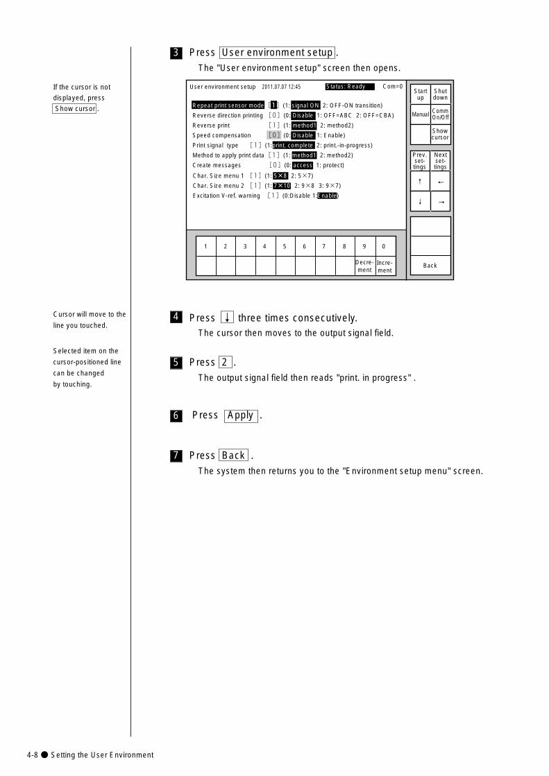
4-8● Setting the User Environment
1 2 3 4 5 6 7 8 9 0
User environment setup
Repeat print sensor mode[1](1: signal ON 2: OFF-ON transition)
Reverse direction printing [0](0: Disable 1: OFF=ABC 2: OFF=CBA)
Reverse print [1](1: method1 2: method2)
Speed compensation [0](0: Disable 1: Enable)
Print signal type [1](1:print. complete 2: print.-in-progress)
Method to apply print data[1](1: method1 2: method2)
Create messages [0](0: access 1: protect)
2011.07.07 12:45
BackIncre-ment
Decre-ment
Manual
Showcursor
Startup
Shutdown
CommOn/Off
Prev.set-tings
Nextset-tings
↑
↓
Status: Ready Com=0
Char. Size menu 1 [1](1: 5×8 2: 5×7)
Char. Size menu 2 [1](1: 7×10 2: 9×8 3: 9×7)
Excitation V-ref. warning [1] (0:Disable 1:Enable)→
←
If the cursor is not
displayed, press
Show cursor .
7
6 Press Apply .
3 Press User environment setup .
The "User environment setup" screen then opens.
5
4 Press ↓ three times consecutively.The cursor then moves to the output signal field.
Press 2 .
The output signal field then reads "print. in progress" .
Press Back .
The system then returns you to the "Environment setup menu" screen.
Cursor will move to the
line you touched.
Selected item on the
cursor-positioned line
can be changed
by touching.
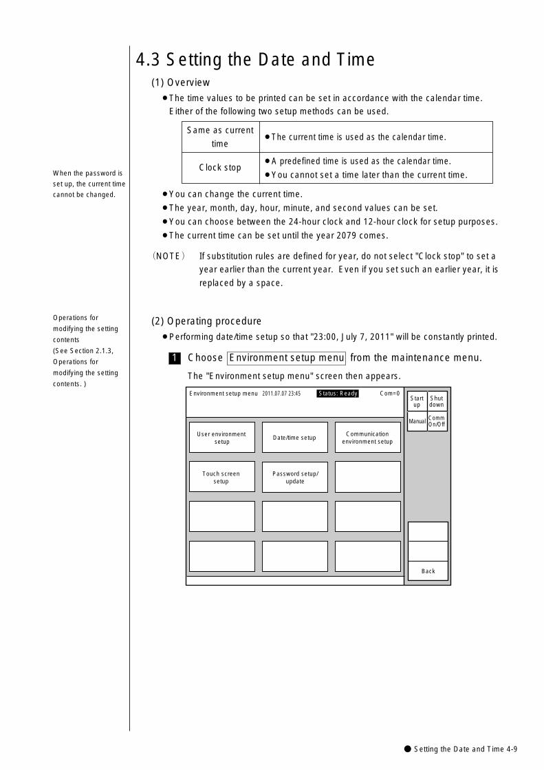
● Setting the Date and Time 4-9
1
4.3 Setting the Date and Time(1) Overview
¡The time values to be printed can be set in accordance with the calendar time.
Either of the following two setup methods can be used.
¡The current time is used as the calendar time.Same as current
time
¡A predefined time is used as the calendar time.
¡You cannot set a time later than the current time.Clock stop
¡You can change the current time.
¡The year, month, day, hour, minute, and second values can be set.
¡You can choose between the 24-hour clock and 12-hour clock for setup purposes.
¡The current time can be set until the year 2079 comes.
When the password is
set up, the current time
cannot be changed.
(2) Operating procedure
¡Performing date/time setup so that "23:00, July 7, 2011" will be constantly printed.
Choose Environment setup menu from the maintenance menu.
Environment setup menu 2011.07.07 23:45
User environment setup
Date/time setupCommunication
environment setup
Touch screensetup
Password setup/update
Back
Manual
Startup
Shutdown
CommOn/Off
Status: Ready Com=0
The "Environment setup menu" screen then appears.
(NOTE) If substitution rules are defined for year, do not select "Clock stop" to set a
year earlier than the current year. Even if you set such an earlier year, it is
replaced by a space.
Operations for
modifying the setting
contents
(See Section 2.1.3,
Operations for
modifying the setting
contents. )
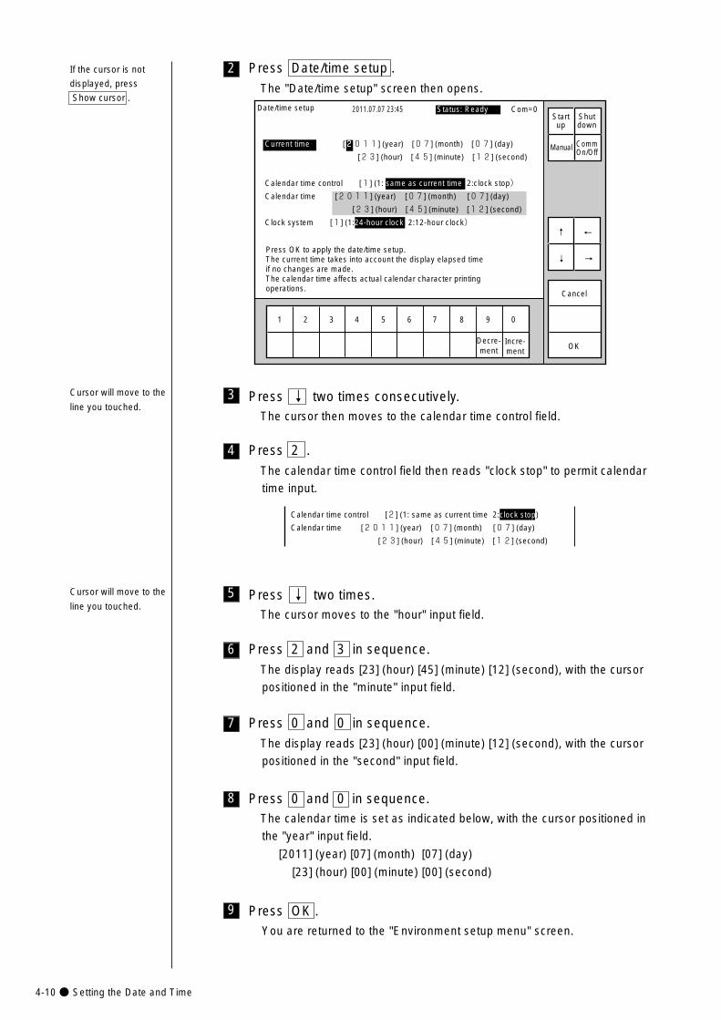
4-10● Setting the Date and Time
8
7
6
5
4
3
2 Press Date/time setup .
The "Date/time setup" screen then opens.
OK
1 2 3 4 5 6 7 8 9 0
Date/time setup 2011.07.07 23:45
Incre-ment
Decre-ment
Cancel
Press OK to apply the date/time setup.The current time takes into account the display elapsed time if no changes are made.The calendar time affects actual calendar character printing operations.
Current time [2011] (year) [07] (month) [07] (day)
[23] (hour) [45] (minute) [12] (second)
Calendar time control [1] (1: same as current time 2:clock stop)
Calendar time [2011] (year) [07] (month) [07] (day)
[23] (hour) [45] (minute) [12] (second)
Clock system [1] (1:24-hour clock 2:12-hour clock)
Manual
↓
↑
→
←
Status: Ready Com=0 Startup
Shutdown
CommOn/Off
Press 2 .
The calendar time control field then reads "clock stop" to permit calendar
time input.
Calendar time control [2] (1: same as current time 2:clock stop)
Calendar time [2011] (year) [07] (month) [07] (day)
[23] (hour) [45] (minute) [12] (second)
Press 2 and 3 in sequence.
The display reads [23] (hour) [45] (minute) [12] (second), with the cursor
positioned in the "minute" input field.
Press ↓ two times.The cursor moves to the "hour" input field.
Press 0 and 0 in sequence.
The display reads [23] (hour) [00] (minute) [12] (second), with the cursor
positioned in the "second" input field.
Press 0 and 0 in sequence.The calendar time is set as indicated below, with the cursor positioned in
the "year" input field.
[2011] (year) [07] (month) [07] (day)
[23] (hour) [00] (minute) [00] (second)
Press ↓ two times consecutively.The cursor then moves to the calendar time control field.
9 Press OK .You are returned to the "Environment setup menu" screen.
If the cursor is not
displayed, press
Show cursor .
Cursor will move to the
line you touched.
Cursor will move to the
line you touched.
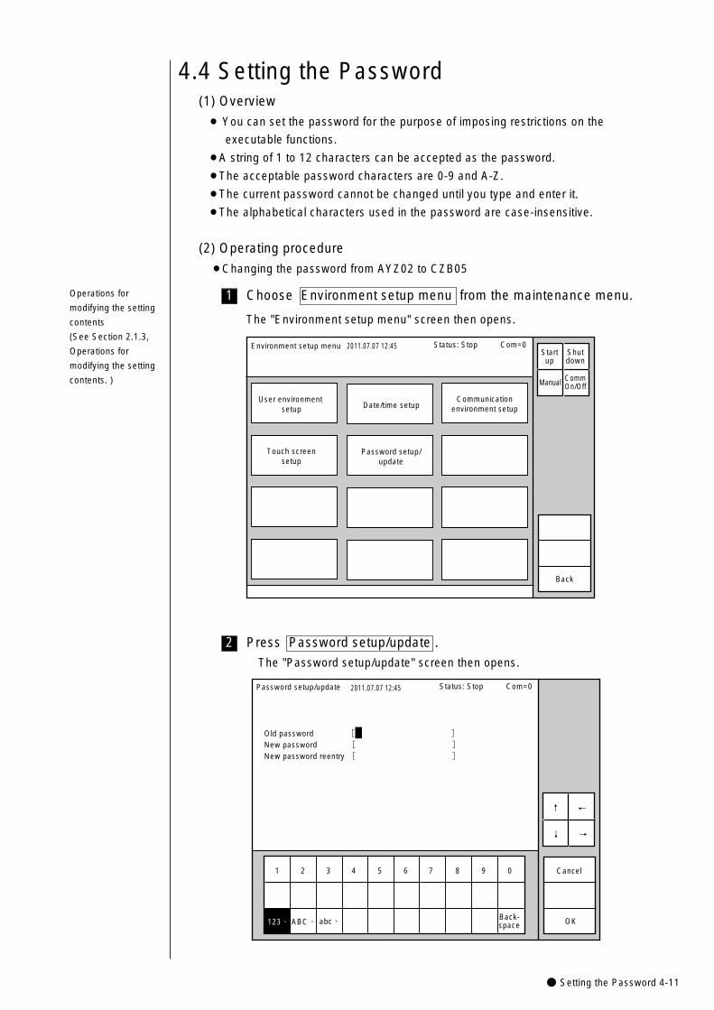
● Setting the Password 4-11
1
4.4 Setting the Password(1) Overview
¡ You can set the password for the purpose of imposing restrictions on the
executable functions.
¡A string of 1 to 12 characters can be accepted as the password.
¡The acceptable password characters are 0-9 and A-Z.
¡The current password cannot be changed until you type and enter it.
¡The alphabetical characters used in the password are case-insensitive.
(2) Operating procedure
¡Changing the password from AYZ02 to CZB05
Choose Environment setup menu from the maintenance menu.
Environment setup menu 2011.07.07 12:45
User environment setup Date/time setup
Communicationenvironment setup
Touch screensetup
Password setup/update
Back
Manual
Status: Stop Com=0 Startup
Shutdown
CommOn/Off
The "Environment setup menu" screen then opens.
2
Old password [ ]New password [ ]New password reentry [ ]
1 2 3 4 5 6 7 8 9 0
Back-space
Password setup/update 2011.07.07 12:45
Cancel
OKABC・�abc・�
↓
↑
→
←
Status: Stop Com=0
123・�
Press Password setup/update .
The "Password setup/update" screen then opens.
Operations for
modifying the setting
contents
(See Section 2.1.3,
Operations for
modifying the setting
contents. )
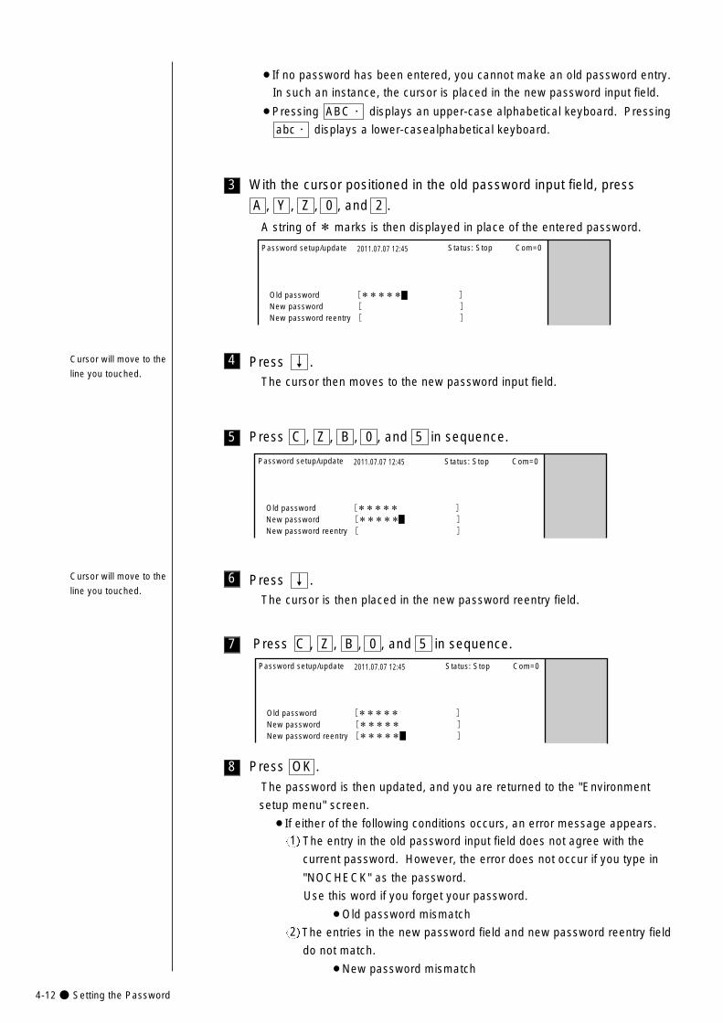
4-12● Setting the Password
6
5
4
3
Old password [***** ]New password [ ]New password reentry [ ]
Password setup/update 2011.07.07 12:45 Status: Stop Com=0
Old password [***** ]New password [***** ]New password reentry [ ]
Password setup/update 2011.07.07 12:45 Status: Stop Com=0
With the cursor positioned in the old password input field, press
A , Y , Z , 0 , and 2 .
A string of * marks is then displayed in place of the entered password.
Press ↓ .The cursor then moves to the new password input field.
Press ↓ .The cursor is then placed in the new password reentry field.
Press C , Z , B , 0 , and 5 in sequence.
¡If no password has been entered, you cannot make an old password entry.
In such an instance, the cursor is placed in the new password input field.
¡Pressing ABC・ displays an upper-case alphabetical keyboard. Pressing
abc・ displays a lower-casealphabetical keyboard.
7
Old password [***** ]New password [***** ]New password reentry [***** ]
Password setup/update 2011.07.07 12:45 Status: Stop Com=0
Press C , Z , B , 0 , and 5 in sequence.
8 Press OK .
The password is then updated, and you are returned to the "Environment
setup menu" screen.
¡If either of the following conditions occurs, an error message appears.
The entry in the old password input field does not agree with the
current password. However, the error does not occur if you type in
"NOCHECK" as the password.
Use this word if you forget your password.
¡Old password mismatch
The entries in the new password field and new password reentry field
do not match.
¡New password mismatch
1
2
Cursor will move to the
line you touched.
Cursor will move to the
line you touched.
● Controlling the Executable Functions 4-13
4.5 Controlling the Executable Functions(1) Overview
¡ You can disable the each functions.
¡When the above functions are disabled, the keys assigned to them will not be
displayed.
¡ No functional limitations can be imposed unless the password entry agrees with the
defined one.
¡Limitations can be imposed on the following functions.
When "Edit message/Select message" is restricted
¡Edit message
¡Calendar conditions
¡Substitution rule setup
¡Count conditions
¡Select message
When "Save message" is restricted
¡Save message
When "Print specifications" are restricted
¡Print specifications
When "Print format" is restricted
¡Print line setup
¡Print format
When "Maintenance" is restricted
¡User environment setup
¡Date/time setup
¡Communication environment setup
¡Touch screen setup
¡Operation management
¡Excitation V update
¡Circulation control
¡Manage message
¡Create user pattern
¡Touch screen setup
¡Copy data
¡Edit standard pattern
¡ If executable functions are restricted, the names of screen will be shaded.
¡ Even when "Print specifications" or "Print format" is restricted, the print specifications or
print format can be changed by recalling print data.
Password setup →See Section 4.4,
Setting the Password.
1
2
3
4
5
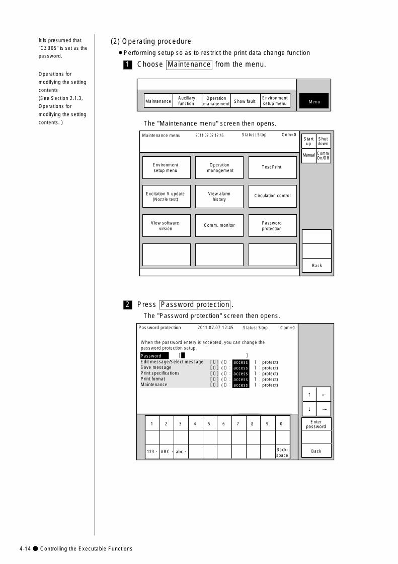
4-14● Controlling the Executable Functions
2
1 Choose Maintenance from the menu.
MaintenanceAuxiliary function
Operationmanagement Show fault Menu
Environmentsetup menu
It is presumed that
"CZB05" is set as the
password.
(2) Operating procedure
¡Performing setup so as to restrict the print data change function
The "Maintenance menu" screen then opens.
Maintenance menu 2011.07.07 12:45
Environmentsetup menu
Operation management
Test Print
Excitation V update(Nozzle test)
View software virsion
View alarmhistory
Circulation control
Passwordprotection
Comm. monitor
Back
Manual
Status: Stop Com=0 Startup
Shutdown
CommOn/Off
Press Password protection .
The "Password protection" screen then opens.
[0](0: access 1:protect)[0](0: access 1:protect)[0](0: access 1:protect)[0](0: access 1:protect)[0](0: access 1:protect)
Password protection
PasswordEdit message/Select messageSave messagePrint specificationsPrint formatMaintenance
[ ]
When the password entery is accepted, you can change the password protection setup.
Enterpassword
2011.07.07 12:45
1 2 3 4 5 6 7 8 9 0
abc・�ABC・�123・� Back-space
Back
↓
↑
→
←
Status: Stop Com=0
Operations for
modifying the setting
contents
(See Section 2.1.3,
Operations for
modifying the setting
contents. )
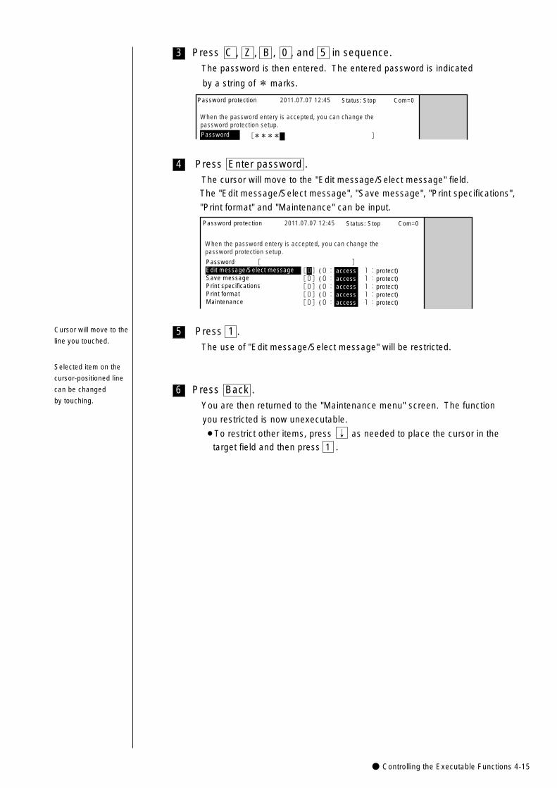
● Controlling the Executable Functions 4-15
6
5
4
3
Password protection
[ ]
When the password entery is accepted, you can change the password protection setup.
2011.07.07 12:45 Status: Stop Com=0
[0](0: access 1:protect)[0](0: access 1:protect)[0](0: access 1:protect)[0](0: access 1:protect)[0](0: access 1:protect)
PasswordEdit message/Select messageSave messagePrint specificationsPrint formatMaintenance
Press Back .
You are then returned to the "Maintenance menu" screen. The function
you restricted is now unexecutable.
¡To restrict other items, press ↓ as needed to place the cursor in the
target field and then press 1 .
Press Enter password .
The cursor will move to the "Edit message/Select message" field.
The "Edit message/Select message", "Save message", "Print specifications",
"Print format" and "Maintenance" can be input.
Press 1 .
The use of "Edit message/Select message" will be restricted.
Press C , Z , B , 0 , and 5 in sequence.
The password is then entered. The entered password is indicated
by a string of * marks.
Password protection
Password [**** ]
When the password entery is accepted, you can change the password protection setup.
2011.07.07 12:45 Status: Stop Com=0
Cursor will move to the
line you touched.
Selected item on the
cursor-positioned line
can be changed
by touching.
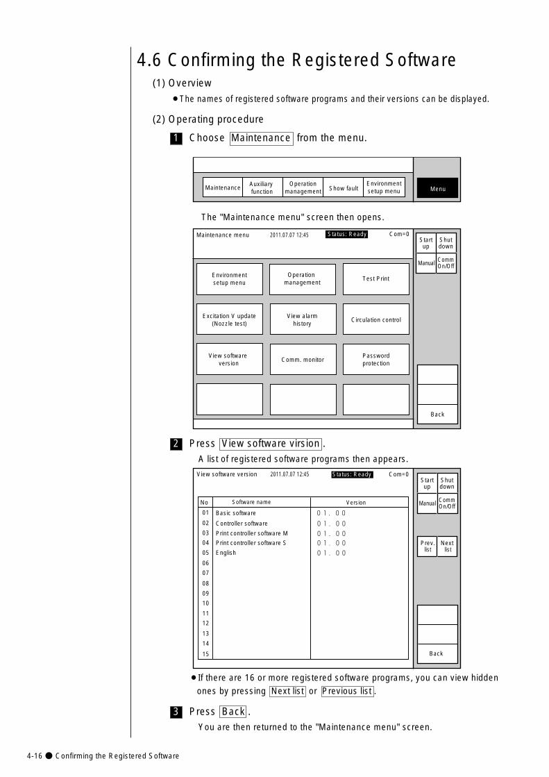
4-16● Confirming the Registered Software
3
2 Press View software virsion .
A list of registered software programs then appears.
Software name
Basic software
Version
01.00
01.00�
01.00�
No
01
02
03
04
05
06
07
08
09
10
11
12
13
14
15
View software version 2011.07.07 12:45
Controller software
Print controller software M
01.00�
01.00�
Print controller software S
English
Back
Manual
Status: Ready Com=0
Prev.list
Next list
Startup
Shutdown
CommOn/Off
¡If there are 16 or more registered software programs, you can view hidden
ones by pressing Next list or Previous list .
Press Back .
You are then returned to the "Maintenance menu" screen.
Maintenance menu 2011.07.07 12:45
Environmentsetup menu
Operation management
Test Print
Excitation V update(Nozzle test)
View software version
View alarmhistory
Circulation control
Passwordprotection
Comm. monitor
Back
Manual
Status: Ready Com=0Startup
Shutdown
CommOn/Off
The "Maintenance menu" screen then opens.
1
4.6 Confirming the Registered Software(1) Overview
¡The names of registered software programs and their versions can be displayed.
Choose Maintenance from the menu.
MaintenanceAuxiliary function
Operationmanagement Show fault Menu
Environmentsetup menu
(2) Operating procedure
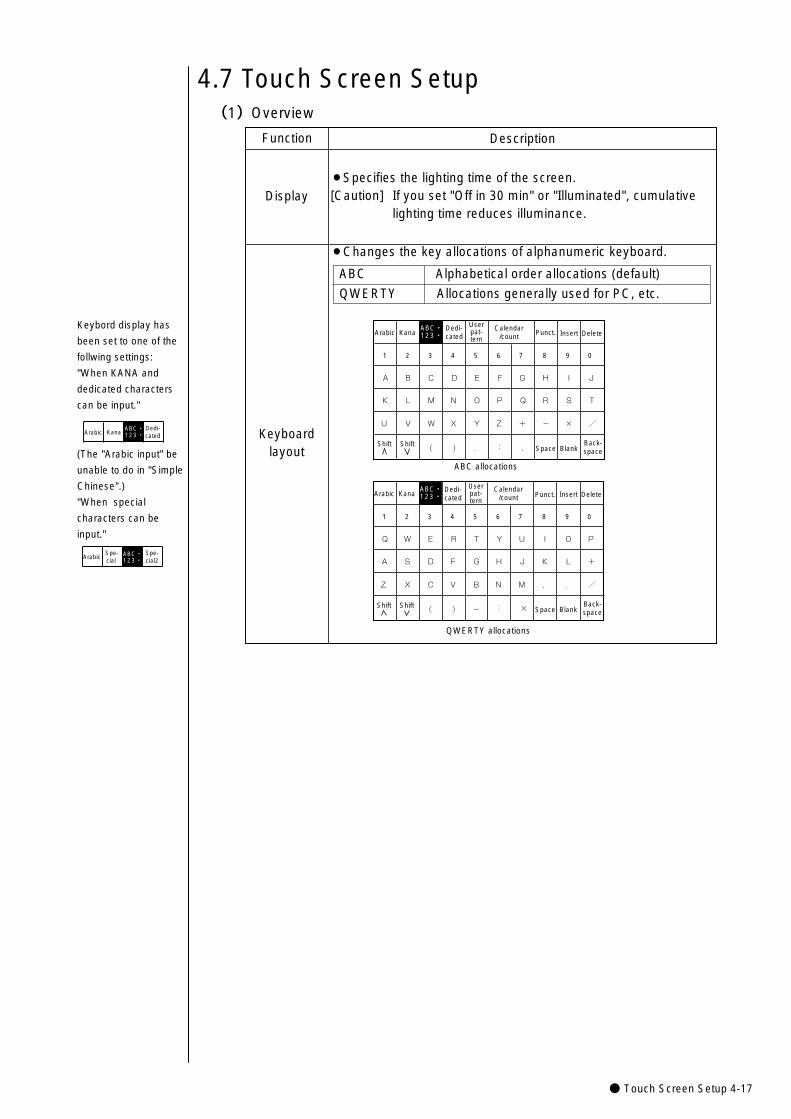
● Touch Screen Setup 4-17
4.7 Touch Screen Setup(1)Overview
Function Description
¡Specifies the lighting time of the screen. [Caution] If you set "Off in 30 min" or "Illuminated", cumulative
lighting time reduces illuminance.
¡Changes the key allocations of alphanumeric keyboard.
Display
Keyboardlayout
ABC Alphabetical order allocations (default)
QWERTY Allocations generally used for PC, etc.
KanaDedi-cated
Userpat-tern
Calendar/count Punct. Insert Delete
K
U
A
L
V
B
M
W
C
N
X
D
O
Y
E
P
Z
F
Q
+
G
R
-
H
S
×
I
T
/
J
Space BlankBack-space( ) . : ,
1 2 3 4 5 6 7 8 9 0
ABC・123・�
ABC allocations
Kana
Arabic
ArabicUserpat-tern
Calendar/count Punct. Insert Delete
A�
Z�
Q�
S�
X�
W�
D�
C�
E�
F�
V�
R�
G�
B�
T�
H�
N�
Y�
J�
M�
U�
K�
,�
I�
L�
.�
O�
+�
/
P�
Space BlankBack-space( ) -� : �
1 2 3 4 5 6 7 8 9 0
ABC・123・�
QWERTY allocations
Dedi-cated
Shift Shift
Shift Shift
Keybord display has
been set to one of the
follwing settings:
"When KANA and
dedicated characters
can be input."
KanaDedi-cated
ABC・123・�Arabic
(The "Arabic input" be
unable to do in "Simple
Chinese".)
"When special
characters can be
input."
Spe-cial
Spe-cial2
ABC・123・�Arabic
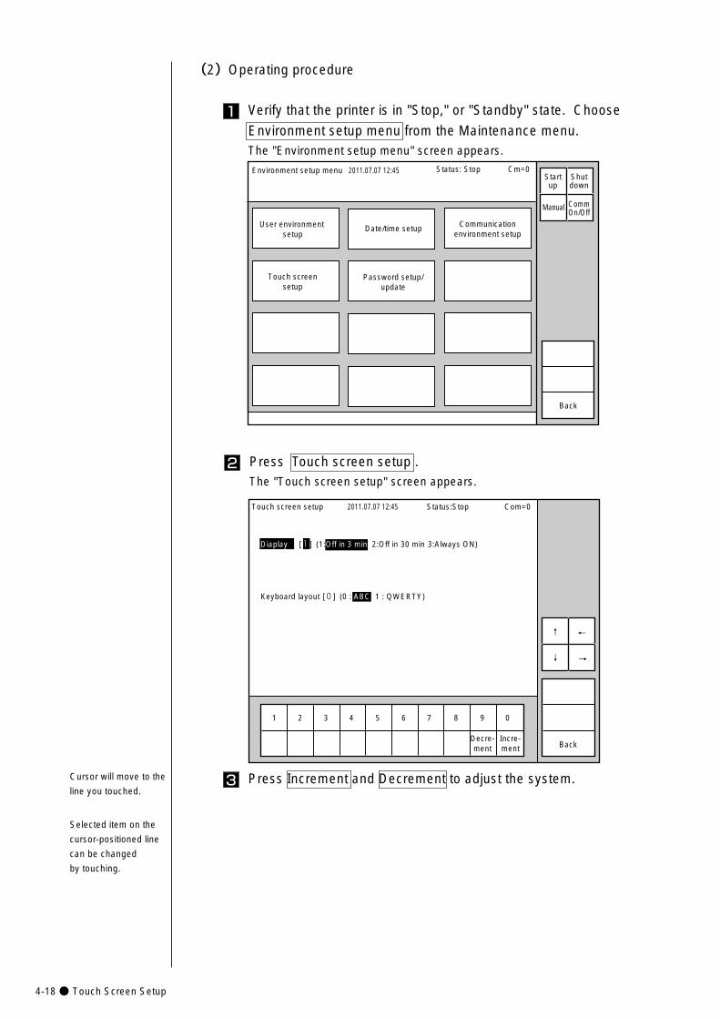
4-18● Touch Screen Setup
2 Press Touch screen setup . The "Touch screen setup" screen appears.
Diaplay [1] (1:Off in 3 min 2:Off in 30 min 3:Always ON)
Keyboard layout [0] (0 : ABC 1 : QWERTY)
Back
1 2 3 4 5 6 7 8 9 0
Incre-ment
Decre-ment
Touch screen setup 2011.07.07 12:45 Status:Stop Com=0
↑
↓ →
←
3 Press Increment and Decrement to adjust the system.
1
(2)Operating procedure
Verify that the printer is in "Stop," or "Standby" state. Choose
Environment setup menu from the Maintenance menu.The "Environment setup menu" screen appears.
Environment setup menu 2011.07.07 12:45
User environment setup
Date/time setup Communicationenvironment setup
Touch screensetup
Password setup/update
Back
Manual
Status: Stop Cm=0Startup
Shutdown
CommOn/Off
Cursor will move to the
line you touched.
Selected item on the
cursor-positioned line
can be changed
by touching.
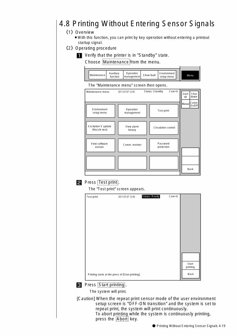
● Printing Without Entering Sensor Signals 4-19
3
2
Press Start printing .
The system will print.
Press Test print .
The "Test print" screen appears.
4.8 Printing Without Entering Sensor Signals(1)Overview
¡With this function, you can print by key operation without entering a printout startup signal.
(2)Operating procedure
1 Verify that the printer is in "Standby" state.
Choose Maintenance from the menu.
MaintenanceAuxiliary function Show fault Menu
Operationmanagement
Environmentsetup menu
The "Maintenance menu" screen then opens.
Maintenance menu 2011.07.07 12:45
Environmentsetup menu
Operation management
Test print
Excitation V update(Nozzle test)
View softwareversion
View alarmhistory
Circulation control
Passwordprotection
Comm. monitor
Back
Manual
Status: Standby Com=0Startup
Shutdown
CommOn/Off
Test print 2011.07.07 12:45
Back
Status: Ready Com=0
Startprinting
Printing starts at the press of [Strat printing].
[Caution] When the repeat print sensor mode of the user environment setup screen is "OFF-ON transition" and the system is set torepeat print, the system will print continuously. To abort printing while the system is continuously printing, press the Abort key.
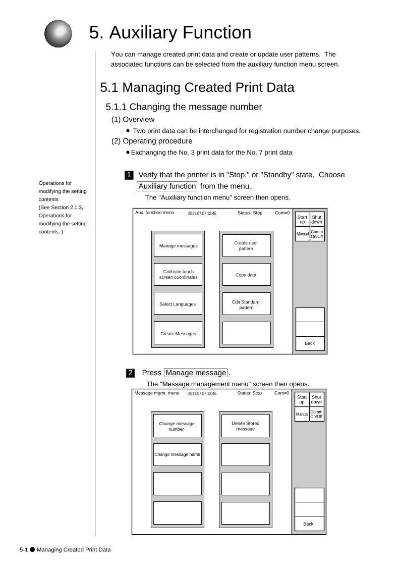
5-1● Managing Created Print Data
5. Auxiliary Function
2
1
2011.07.07 12:45
Manage messagesCreate user
pattern
Calibrate touchscreen coordinates
Aux. function menu
Back
Manual
Status: Stop Com=0 Startup
Shutdown
CommOn/Off
Copy data
Select Languages Edit Standard pattern
Create Messages
(1) Overview
¡ Two print data can be interchanged for registration number change purposes.
(2) Operating procedure
¡Exchanging the No. 3 print data for the No. 7 print data
5.1 Managing Created Print Data
You can manage created print data and create or update user patterns. The
associated functions can be selected from the auxiliary function menu screen.
5.1.1 Changing the message number
Verify that the printer is in "Stop," or "Standby" state. Choose
Auxiliary function from the menu.
The "Auxiliary function menu" screen then opens.
Press Manage message .
The "Message management menu" screen then opens.Message mgmt. menu 2011.07.07 12:45
Change messagenumber
Change message name
Delete Storedmassage
Back
�
Manual
Status: Stop Com=0 Startup
Shutdown
CommOn/Off
Operations for
modifying the setting
contents
(See Section 2.1.3,
Operations for
modifying the setting
contents. )
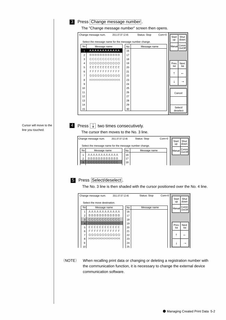
● Managing Created Print Data 5-2
5
4
3 Press Change message number .
The "Change message number" screen then opens.
Press ↓ two times consecutively.The cursor then moves to the No. 3 line.
No Message name
AAAAAAAAAAAA
No Message name
1
2
3
4
5
6
7
8
9
10
11
12
13
14
15
Change message num. 2011.07.07 12:45
Select/deselect
16
17
18
19
20
21
22
23
24
25
26
27
28
29
30
BBBBBBBBBBBB
CCCCCCCCCCCC
DDDDDDDDDDDD
EEEEEEEEEEEE
FFFFFFFFFFFF
GGGGGGGGGGGG
HHHHHHHHHHHH
Select the message name for the message number change.
Cancel
Manual
Prev.list
Next list
↓
↑
→
←
Status: Stop Com=0 Startup
Shutdown
CommOn/Off
No Message name
AAAAAAAAAAAA�
No Message name
1 2
3
Change message num. 2011.07.07 12:45
1617
18
BBBBBBBBBBBBCCCCCCCCCCCC
Select the message name for the message number change.
Status: Stop Com=0
Manual
Startup
Shutdown
CommOn/Off
Press Select/deselect .
The No. 3 line is then shaded with the cursor positioned over the No. 4 line.
AAAAAAAAAAAA�BBBBBBBBBBBB�CCCCCCCCCCCC�DDDDDDDDDDDD�EEEEEEEEEEEE�FFFFFFFFFFFF�GGGGGGGGGGGG�HHHHHHHHHHHH�
No Message name No Message name
1
2
3
4
5
6
7
8
9
10
Change message num. 2011.07.07 12:45
16
17
18
19
20
21
22
23
24
25
Select the move destination.
Manual
Prev.list
Next list
↓
↑
→
←
Status: Stop Com=0 Startup
Shutdown
CommOn/Off
(NOTE) When recalling print data or changing or deleting a registration number with
the communication function, it is necessary to change the external device
communication software.
Cursor will move to the
line you touched.
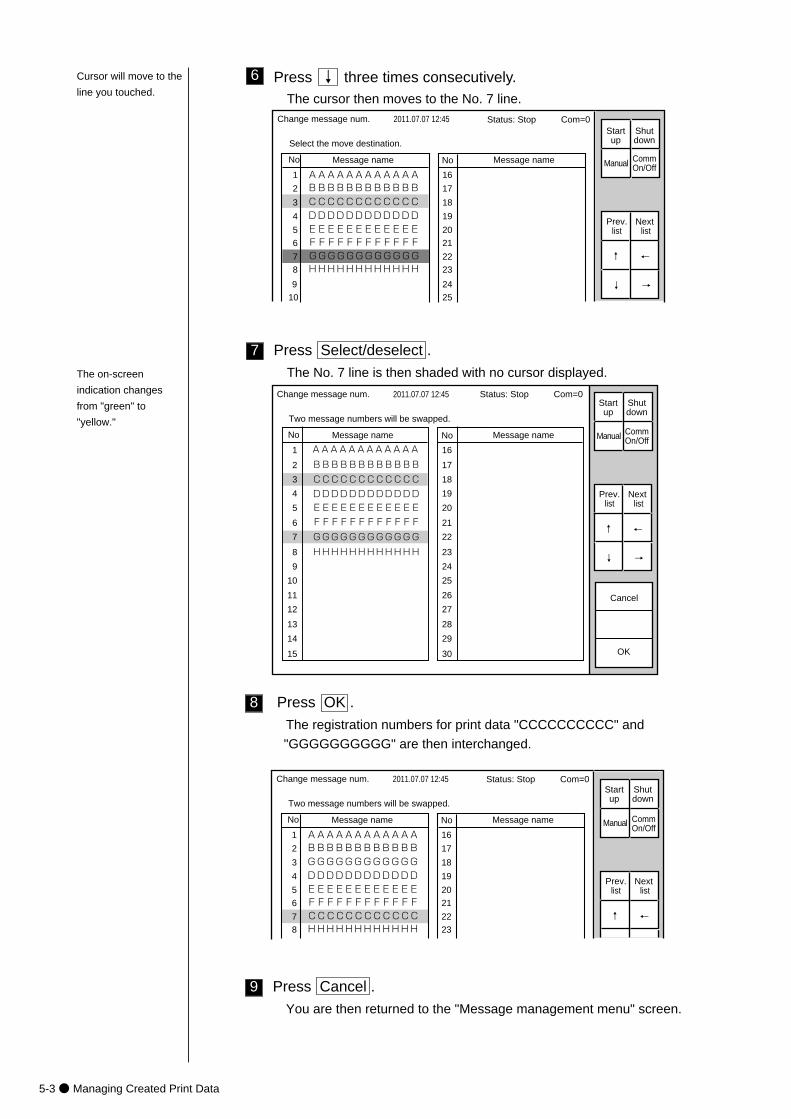
5-3● Managing Created Print Data
9
8
7
6 Press ↓ three times consecutively.The cursor then moves to the No. 7 line.
AAAAAAAAAAAA�BBBBBBBBBBBB�CCCCCCCCCCCC�DDDDDDDDDDDD�EEEEEEEEEEEE�FFFFFFFFFFFF�GGGGGGGGGGGG�HHHHHHHHHHHH�
No Message name No Message name
1
2
3
4
5
6
7
8
9
10
Change message num. 2011.07.07 12:45
16
17
18
19
20
21
22
23
24
25
Select the move destination.
Manual
Prev.list
Next list
↓
↑
→
←
Status: Stop Com=0 Startup
Shutdown
CommOn/Off
Press Select/deselect .
The No. 7 line is then shaded with no cursor displayed.
No Message name
AAAAAAAAAAAA�
No Message name
1
2
3
4
5
6
7
8
9
10
11
12
13
14
15
Change message num. 2011.07.07 12:45
OK
16
17
18
19
20
21
22
23
24
25
26
27
28
29
30
BBBBBBBBBBBB
CCCCCCCCCCCC
DDDDDDDDDDDD
EEEEEEEEEEEE
FFFFFFFFFFFF
GGGGGGGGGGGG
HHHHHHHHHHHH
Two message numbers will be swapped.
Cancel
Manual
Prev.list
Next list
↓
↑
→
←
Status: Stop Com=0 Startup
Shutdown
CommOn/Off
Press OK .
The registration numbers for print data "CCCCCCCCCC" and
"GGGGGGGGGG" are then interchanged.
AAAAAAAAAAAA�BBBBBBBBBBBB�GGGGGGGGGGGG�DDDDDDDDDDDD�EEEEEEEEEEEE�FFFFFFFFFFFF�CCCCCCCCCCCC�HHHHHHHHHHHH�
No Message name No Message name
1
2
3
4
5
6
7
8
Change message num. 2011.07.07 12:45
16
17
18
19
20
21
22
23
Two message numbers will be swapped.
Manual
Prev.list
Next list
↑ ←
Status: Stop Com=0 Startup
Shutdown
CommOn/Off
Press Cancel .
You are then returned to the "Message management menu" screen.
The on-screen
indication changes
from "green" to
"yellow."
Cursor will move to the
line you touched.
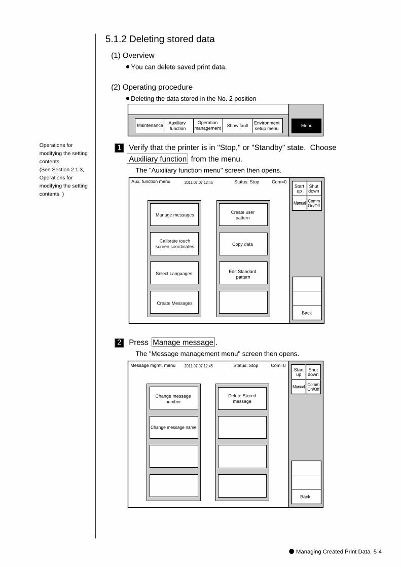
● Managing Created Print Data 5-4
2
1
(1) Overview
¡You can delete saved print data.
(2) Operating procedure
¡Deleting the data stored in the No. 2 position
5.1.2 Deleting stored data
Maintenance Auxiliary function
Show fault MenuOperation
managementEnvironmentsetup menu
2011.07.07 12:45
Manage messagesCreate user
pattern
Calibrate touchscreen coordinates
Aux. function menu
Back
Manual
Status: Stop Com=0 Startup
Shutdown
CommOn/Off
Copy data
Select Languages Edit Standard pattern
Create Messages
Verify that the printer is in "Stop," or "Standby" state. Choose
Auxiliary function from the menu.
The "Auxiliary function menu" screen then opens.
Press Manage message .
The "Message management menu" screen then opens.
Message mgmt. menu 2011.07.07 12:45
Change messagenumber
Change message name
Delete Storedmessage
Back
�
Manual
Status: Stop Com=0Startup
Shutdown
CommOn/Off
Operations for
modifying the setting
contents
(See Section 2.1.3,
Operations for
modifying the setting
contents. )
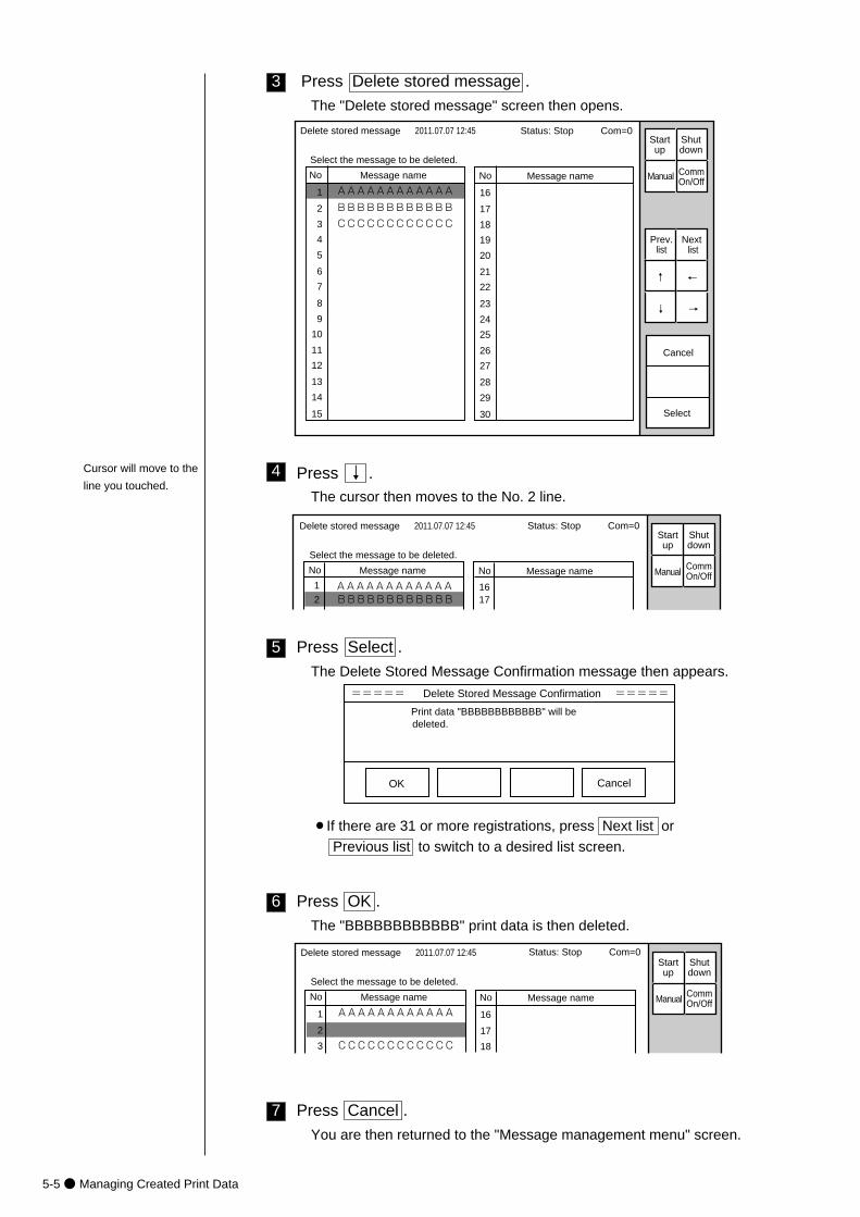
5-5● Managing Created Print Data
7
6
5
4
3 Press Delete stored message .
The "Delete stored message" screen then opens.
Press ↓ .The cursor then moves to the No. 2 line.
Press Select .
The Delete Stored Message Confirmation message then appears.
Press OK .
The "BBBBBBBBBBBB" print data is then deleted.
No Message name
AAAAAAAAAAAA�
No Message name
Delete stored message 2011.07.07 12:45
Select
Select the message to be deleted.
1
2
3
4
5
6
7
8
9
10
11
12
13
14
15
16
17
18
19
20
21
22
23
24
25
26
27
28
29
30
BBBBBBBBBBBB
CCCCCCCCCCCC
Cancel
Manual
Prev.list
Next list
↓
↑
→
←
Status: Stop Com=0Startup
Shutdown
CommOn/Off
===== Delete Stored Message Confirmation =====
Print data "BBBBBBBBBBBB" will be deleted.
OK Cancel
No Message name
AAAAAAAAAAAA�
No Message name
Delete stored message 2011.07.07 12:45
Select the message to be deleted.
1
2
3
16
17
18CCCCCCCCCCCC
Manual
Status: Stop Com=0Startup
Shutdown
CommOn/Off
Press Cancel .
You are then returned to the "Message management menu" screen.
¡If there are 31 or more registrations, press Next list or
Previous list to switch to a desired list screen.
No Message name
AAAAAAAAAAAA�
No Message name
Delete stored message 2011.07.07 12:45
Select the message to be deleted.
1
21617BBBBBBBBBBBB
Manual
Status: Stop Com=0Startup
Shutdown
CommOn/Off
Cursor will move to the
line you touched.
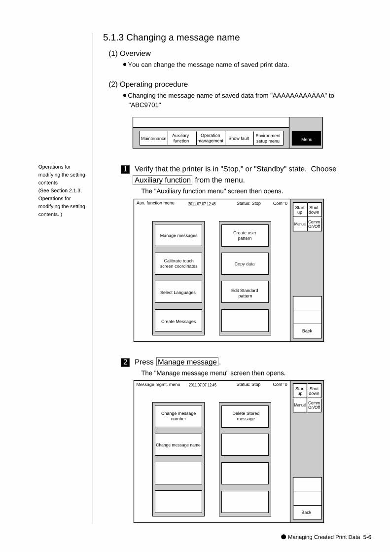
● Managing Created Print Data 5-6
2
1
MaintenanceAuxiliary function Show fault Menu
Operationmanagement
Environmentsetup menu
2011.07.07 12:45
Manage messagesCreate user
pattern
Calibrate touchscreen coordinates
Aux. function menu
Back
Manual
Status: Stop Com=0 Startup
Shutdown
CommOn/Off
Copy data
Select Languages Edit Standard pattern
Create Messages
(1) Overview
¡You can change the message name of saved print data.
(2) Operating procedure
¡Changing the message name of saved data from "AAAAAAAAAAAA" to
"ABC9701"
5.1.3 Changing a message name
Verify that the printer is in "Stop," or "Standby" state. Choose
Auxiliary function from the menu.
The "Auxiliary function menu" screen then opens.
Press Manage message .
The "Manage message menu" screen then opens.
Message mgmt. menu 2011.07.07 12:45
Change messagenumber
Change message name
Delete Storedmessage
Back
Manual
Status: Stop Com=0Startup
Shutdown
CommOn/Off
Operations for
modifying the setting
contents
(See Section 2.1.3,
Operations for
modifying the setting
contents. )
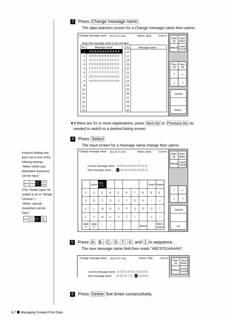
5-7● Managing Created Print Data
6
5
4
3 Press Change message name .
The data selection screen for a Change message name then opens.
No Message name
AAAAAAAAAAAA
No Message name
Change message name 2011.07.07 12:45
Select the message name to be changed.
1
2
3
4
5
6
7
8
9
10
11
12
13
14
15
16
17
18
19
20
21
22
23
24
25
26
27
28
29
30
BBBBBBBBBBBB
CCCCCCCCCCCC
DDDDDDDDDDDD
EEEEEEEEEEEE
FFFFFFFFFFFF
GGGGGGGGGGGG
HHHHHHHHHHHH
Select
Cancel
Manual
Prev.list
Next list
↓
↑
→
←
Status: Stop Com=0Startup
Shutdown
CommOn/Off
Press Select .
The input screen for a message name change then opens.
Kana Insert Delete
K
U
A
L
V
B
M
W
C
N
X
D
O
Y
E
P
Z
F
Q
+
G
R
-
H
S
×
I
T
/
J
( ) . : ,
Change message name 2011.07.07 12:45
1 2 3 4 5 6 7 8 9 0
ABC・123・�
Current message name AAAAAAAAAAAA
New message name [AAAAAAAAAAAA]
SpaceBack-space
Cancel
OK
Manual
↓
↑
→
←
Status: Stop Com=0Startup
Shutdown
CommOn/Off
Shift Shift
¡If there are 31 or more registrations, press Next list or Previous list as
needed to switch to a desired listing screen.
Change message name 2011.07.07 12:45
Current message name AAAAAAAAAAAA
New message name [ABC9701AAAAA]
Manual
Status: Stop Com=0Startup
Shutdown
CommOn/Off
Press A , B , C , 9 , 7 , 0 , and 1 in sequence.
The new message name field then reads "ABC9701AAAAA".
Press Delete five times consecutively.
Keybord display has
been set to one of the
follwing settings:
"When KANA and
dedicated characters
can be input."
KanaDedi-cated
ABC・123・�Arabic
(The "Arabic input" be
unable to do in "Simple
Chinese".)
"When special
characters can be
input."
Spe-cial
Spe-cial2
ABC・123・�Arabic
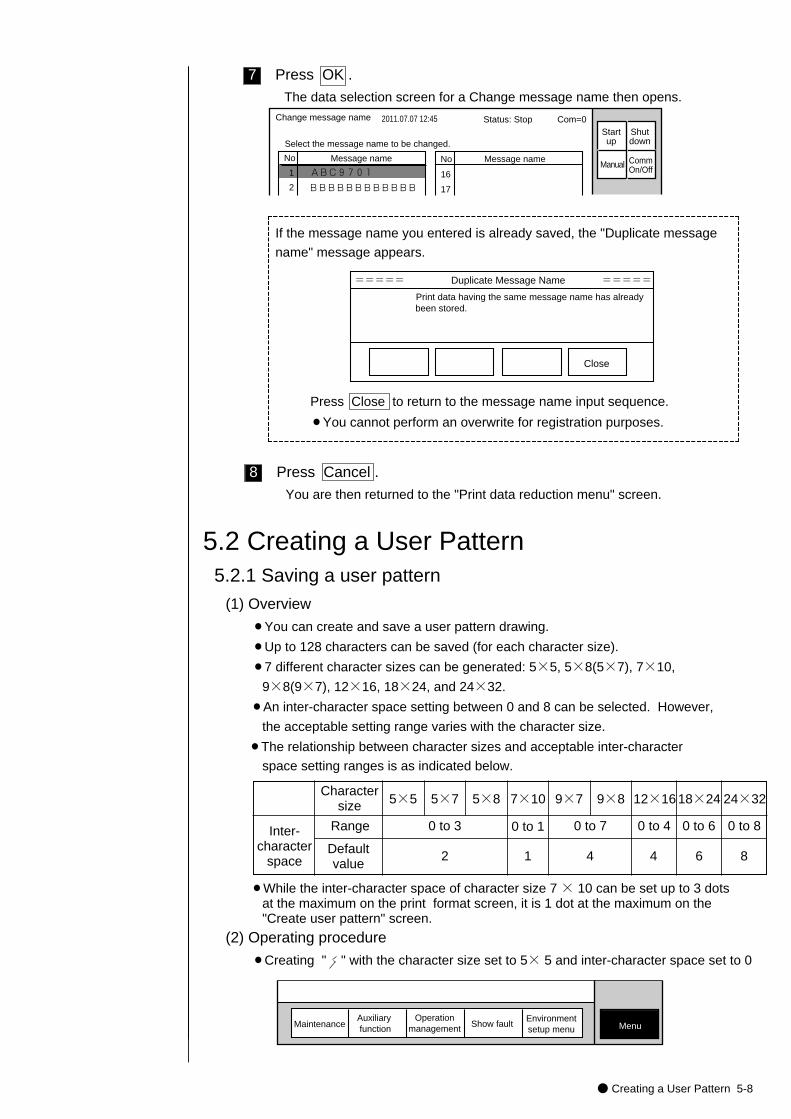
● Creating a User Pattern 5-8
8
7 Press OK .
The data selection screen for a Change message name then opens.
No Message name
ABC9701�
No Message name
Change message name 2011.07.07 12:45
Select the message name to be changed.
1
2
16
17BBBBBBBBBBBB
Manual
Status: Stop Com=0Startup
Shutdown
CommOn/Off
Press Cancel .
You are then returned to the "Print data reduction menu" screen.
If the message name you entered is already saved, the "Duplicate message
name" message appears.
===== Duplicate Message Name =====
Print data having the same message name has already been stored.
Close
Press Close to return to the message name input sequence.
¡You cannot perform an overwrite for registration purposes.
(1) Overview
¡You can create and save a user pattern drawing.
¡Up to 128 characters can be saved (for each character size).
¡7 different character sizes can be generated: 5×5, 5×8(5×7), 7×10,
9×8(9×7), 12×16, 18×24, and 24×32.
¡An inter-character space setting between 0 and 8 can be selected. However,
the acceptable setting range varies with the character size.
¡The relationship between character sizes and acceptable inter-character
space setting ranges is as indicated below.
5.2.1 Saving a user pattern
5.2 Creating a User Pattern
Charactersize 5×5
Range
Defaultvalue
5×7 5×8 7×10 9×7 9×8 12×16 18×24 24×32
0 to 3 0 to 1 0 to 7 0 to 4 0 to 6 0 to 8
2 1 4 4 6 8
MaintenanceAuxiliary function Show fault Menu
Operationmanagement
Environmentsetup menu
(2) Operating procedure
¡Creating " " with the character size set to 5× 5 and inter-character space set to 0
Inter-character
space
¡While the inter-character space of character size 7 × 10 can be set up to 3 dots at the maximum on the print format screen, it is 1 dot at the maximum on the "Create user pattern" screen.
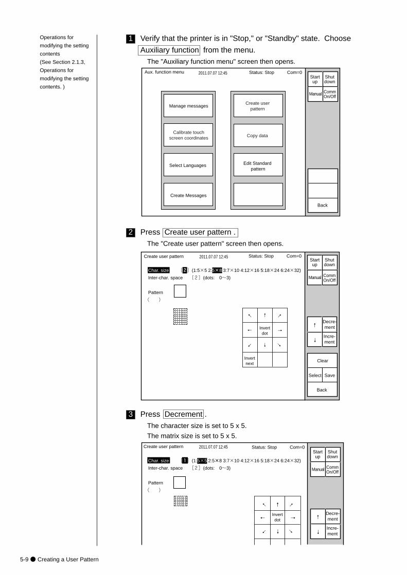
5-9● Creating a User Pattern
3
2
1
2011.07.07 12:45
Manage messagesCreate user
pattern
Calibrate touchscreen coordinates
Aux. function menu
Back
Manual
Status: Stop Com=0 Startup
Shutdown
CommOn/Off
Copy data
Select Languages Edit Standard pattern
Create Messages
Verify that the printer is in "Stop," or "Standby" state. Choose
Auxiliary function from the menu.
The "Auxiliary function menu" screen then opens.
Press Create user pattern .
The "Create user pattern" screen then opens.
→
↓
↑
←
→
↓
↑
←
Invertnext
Invertdot
Create user pattern 2011.07.07 12:45
Char. size [2](1:5×5 2:5×8 3:7×10 4:12×16 5:18×24 6:24×32)
Inter-char. space [2](dots: 0~3)
Pattern
( )
Select
Clear
Back
Save
Manual
↓
↑
Incre-ment
Decre-ment
Status: Stop Com=0Startup
Shutdown
CommOn/Off
Press Decrement .
The character size is set to 5 x 5.
The matrix size is set to 5 x 5.
→�
↓�
↑�
←�Invertdot
Create user pattern 2011.07.07 12:45
Char. size [1](1:5×5 2:5×8 3:7×10 4:12×16 5:18×24 6:24×32)
Inter-char. space [2](dots: 0~3)
Pattern
( )
Manual
↓
↑
Status: Stop Com=0Startup
Shutdown
CommOn/Off
→
↓
↑
←Incre-ment
Decre-ment
Operations for
modifying the setting
contents
(See Section 2.1.3,
Operations for
modifying the setting
contents. )
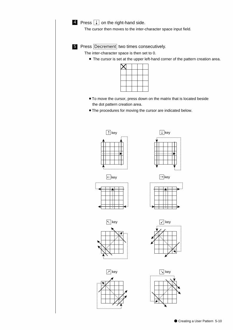
● Creating a User Pattern 5-10
5
4
¡To move the cursor, press down on the matrix that is located beside
the dot pattern creation area.
¡The procedures for moving the cursor are indicated below.
↑ key ↓ key
← key → key
key← key←
key←
key←
Press ↓ on the right-hand side.The cursor then moves to the inter-character space input field.
Press Decrement two times consecutively.
The inter-character space is then set to 0.
¡ The cursor is set at the upper left-hand corner of the pattern creation area.
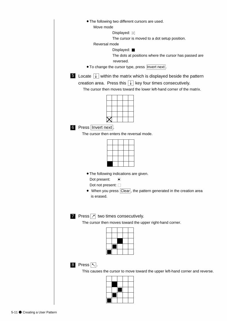
5-11● Creating a User Pattern
8
7
6
5
Press Invert next .
The cursor then enters the reversal mode.
¡The following indications are given.
Dot present:
Dot not present:
¡ When you press Clear , the pattern generated in the creation area
is erased.
¡The following two different cursors are used.
Move mode
Displayed:
The cursor is moved to a dot setup position.
Reversal mode
Displayed:
The dots at positions where the cursor has passed are
reversed.
¡To change the cursor type, press Invert next .
Locate ↓ within the matrix which is displayed beside the pattern
creation area. Press this ↓ key four times consecutively.The cursor then moves toward the lower left-hand corner of the matrix.
Press two times consecutively.
The cursor then moves toward the upper right-hand corner.
Press .
This causes the cursor to move toward the upper left-hand corner and reverse.
↓
↓
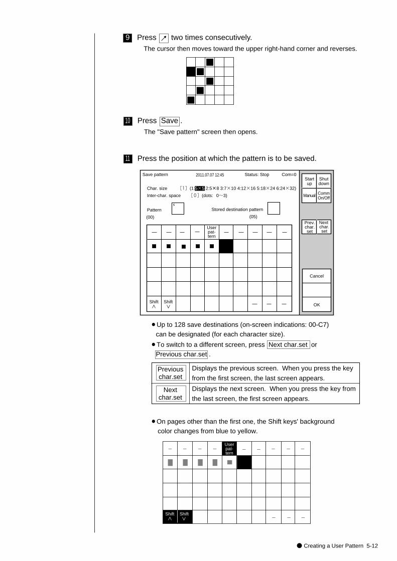
● Creating a User Pattern 5-12
11
10
9 Press two times consecutively.
The cursor then moves toward the upper right-hand corner and reverses.
Press Save .
The "Save pattern" screen then opens.
Save pattern 2011.07.07 12:45
Char. size [1](1:5×5 2:5×8 3:7×10 4:12×16 5:18×24 6:24×32)
Inter-char. space [0](dots: 0~3)
Pattern
(00)
OK
Userpat-tern
Stored destination pattern
(05)
Cancel
Manual
Prev.char.set
Next char.set
Status: Stop Com=0Startup
Shutdown
CommOn/Off
Shift Shift
Previouschar.set
Displays the previous screen. When you press the key
from the first screen, the last screen appears.
Next char.set
¡Up to 128 save destinations (on-screen indications: 00-C7)
can be designated (for each character size).
¡To switch to a different screen, press Next char.set or
Previous char.set .
¡On pages other than the first one, the Shift keys' background
color changes from blue to yellow.
-� -� -� -�Userpat-tern
-� -� -�-� -�
-� -� -�Shift Shift
Displays the next screen. When you press the key from
the last screen, the first screen appears.
Press the position at which the pattern is to be saved.
↓
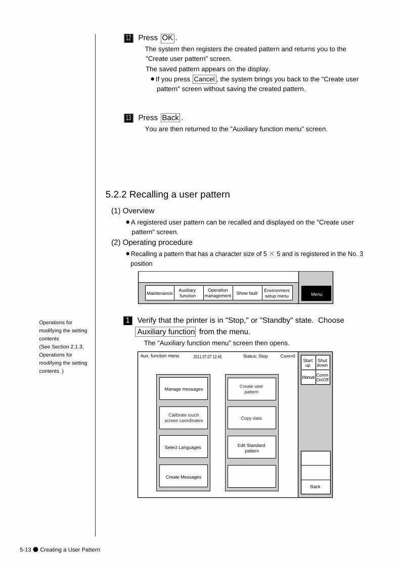
5-13● Creating a User Pattern
1
13
12 Press OK .
The system then registers the created pattern and returns you to the
"Create user pattern" screen.
The saved pattern appears on the display.
¡If you press Cancel , the system brings you back to the "Create user
pattern" screen without saving the created pattern.
Press Back .
You are then returned to the "Auxiliary function menu" screen.
MaintenanceAuxiliary function Show fault Menu
Operationmanagement
Environmentsetup menu
(1) Overview
¡A registered user pattern can be recalled and displayed on the "Create user
pattern" screen.
(2) Operating procedure
¡Recalling a pattern that has a character size of 5 × 5 and is registered in the No. 3
position
5.2.2 Recalling a user pattern
2011.07.07 12:45
Manage messagesCreate user
pattern
Calibrate touchscreen coordinates
Aux. function menu
Back
Manual
Status: Stop Com=0 Startup
Shutdown
CommOn/Off
Copy data
Select Languages Edit Standard pattern
Create Messages
Verify that the printer is in "Stop," or "Standby" state. Choose
Auxiliary function from the menu.
The "Auxiliary function menu" screen then opens.
Operations for
modifying the setting
contents
(See Section 2.1.3,
Operations for
modifying the setting
contents. )
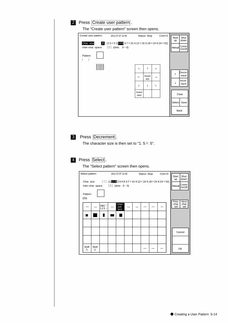
● Creating a User Pattern 5-14
4
3
2 Press Create user pattern .
The "Create user pattern" screen then opens.
→
↓
↑
←
Invertnext
Invertdot
Create user pattern 2011.07.07 12:45
Char. size [2](1:5×5 2:5×8 3:7×10 4:12×16 5:18×24 6:24×32)
Inter-char. space [2](dots: 0~3)
Pattern
( )
Select
Clear
Back
Save
Manual
↓
↑
Incre-ment
Decre-ment
Status: Stop Com=0Startup
Shutdown
CommOn/Off
→
↓
↑
←
Press Select .
The "Select pattern" screen then opens.
Select pattern 2011.07.07 12:45
Char. size [1](1:5×5 2:5×8 3:7×10 4:12×16 5:18×24 6:24×32)
Inter-char. space [0](dots: 0~3)
Pattern
(00)
OK
Userpat-tern
Cancel
Manual
Prev.char.set
Next char.set
Status: Stop Com=0Startup
Shutdown
CommOn/Off
ABC・�123・�
Shift Shift
Press Decrement .
The character size is then set to "1: 5× 5".
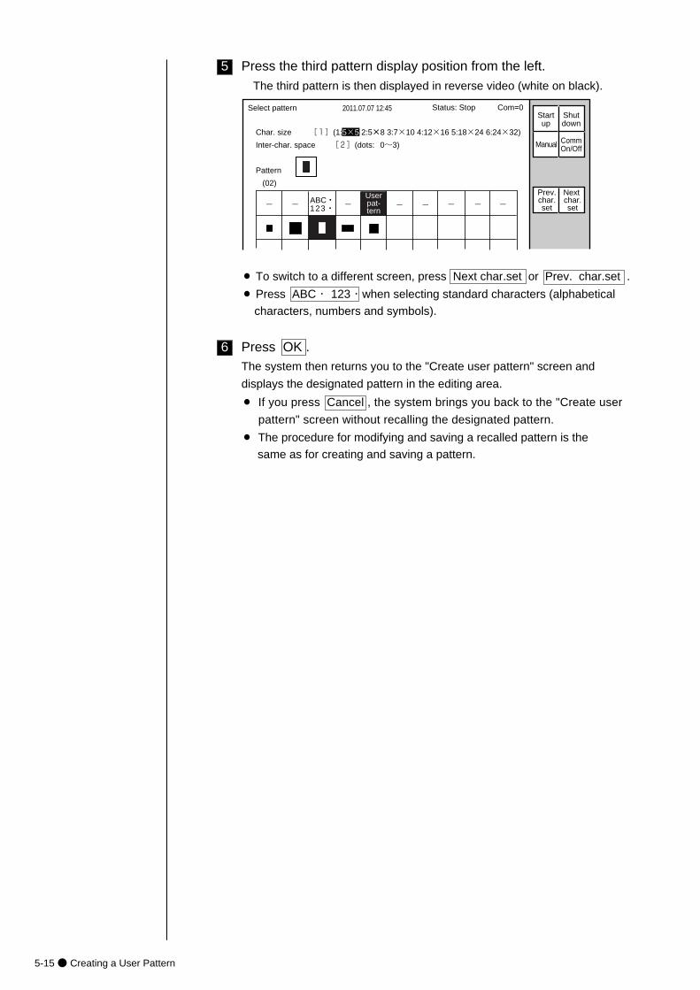
5-15● Creating a User Pattern
5 Press the third pattern display position from the left.
The third pattern is then displayed in reverse video (white on black).
-� -� -�Userpat-tern
-� -� -�-� -�
Select pattern 2011.07.07 12:45
Char. size [1](1:5×5 2:5×8 3:7×10 4:12×16 5:18×24 6:24×32)
Inter-char. space [2](dots: 0~3)
Pattern
(02)
Manual
Prev.char.set
Next char.set
Status: Stop Com=0Startup
Shutdown
CommOn/Off
ABC・�123・�
6 Press OK .The system then returns you to the "Create user pattern" screen and
displays the designated pattern in the editing area.
¡ If you press Cancel , the system brings you back to the "Create user
pattern" screen without recalling the designated pattern.
¡ The procedure for modifying and saving a recalled pattern is the
same as for creating and saving a pattern.
¡ To switch to a different screen, press Next char.set or Prev. char.set .
¡ Press ABC・ 123・when selecting standard characters (alphabetical
characters, numbers and symbols).
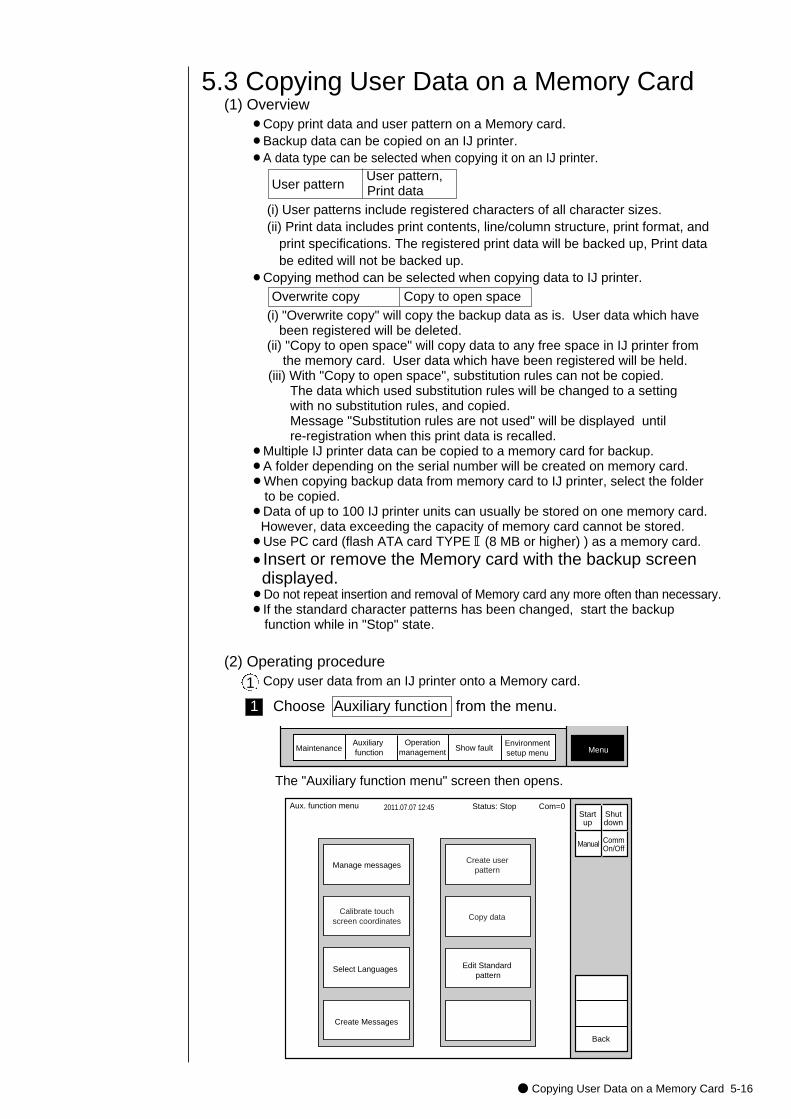
● Copying User Data on a Memory Card 5-16
5.3 Copying User Data on a Memory Card
1 Choose Auxiliary function from the menu.
The "Auxiliary function menu" screen then opens.
MaintenanceAuxiliary function Show fault Menu
Operationmanagement
Environmentsetup menu
2011.07.07 12:45
Manage messagesCreate user
pattern
Calibrate touchscreen coordinates
Aux. function menu
Back
Manual
Status: Stop Com=0 Startup
Shutdown
CommOn/Off
Copy data
Select Languages Edit Standard pattern
Create Messages
(1) Overview¡Copy print data and user pattern on a Memory card.¡Backup data can be copied on an IJ printer.¡A data type can be selected when copying it on an IJ printer.
User pattern User pattern,Print data
(i) User patterns include registered characters of all character sizes.(ii) Print data includes print contents, line/column structure, print format, and
print specifications. The registered print data will be backed up, Print data be edited will not be backed up.
¡Copying method can be selected when copying data to IJ printer.Overwrite copy Copy to open space
(i) "Overwrite copy" will copy the backup data as is. User data which have been registered will be deleted.
(ii) "Copy to open space" will copy data to any free space in IJ printer from the memory card. User data which have been registered will be held.
(iii) With "Copy to open space", substitution rules can not be copied. The data which used substitution rules will be changed to a settingwith no substitution rules, and copied.Message "Substitution rules are not used" will be displayed until re-registration when this print data is recalled.
¡Multiple IJ printer data can be copied to a memory card for backup.¡A folder depending on the serial number will be created on memory card.¡When copying backup data from memory card to IJ printer, select the folder
to be copied.¡Data of up to 100 IJ printer units can usually be stored on one memory card.
However, data exceeding the capacity of memory card cannot be stored.¡Use PC card (flash ATA card TYPE (8 MB or higher) ) as a memory card.¡Insert or remove the Memory card with the backup screen
displayed.¡Do not repeat insertion and removal of Memory card any more often than necessary.¡If the standard character patterns has been changed, start the backup
function while in "Stop" state.
(2) Operating procedureCopy user data from an IJ printer onto a Memory card.1
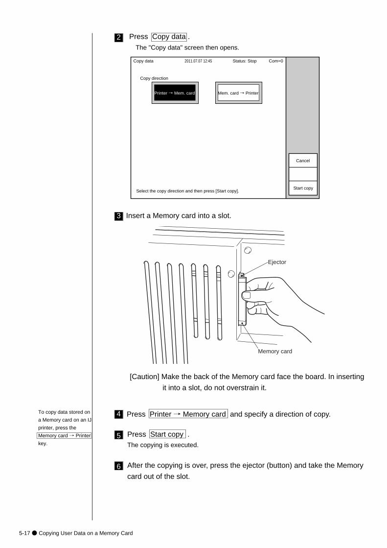
5-17● Copying User Data on a Memory Card
Insert a Memory card into a slot.3
Ejector
Memory card
4 Press Printer → Memory card and specify a direction of copy.
5 Press Start copy .The copying is executed.
[Caution] Make the back of the Memory card face the board. In inserting
it into a slot, do not overstrain it.
6 After the copying is over, press the ejector (button) and take the Memory
card out of the slot.
To copy data stored on
a Memory card on an IJ
printer, press the
Memory card → Printer
key.
2011.07.07 12:45Copy data
Start copy
Status: Stop Com=0
Copy direction
Printer → Mem. card Mem. card → Printer
Cancel
Select the copy direction and then press [Start copy].
2 Press Copy data .
The "Copy data" screen then opens.
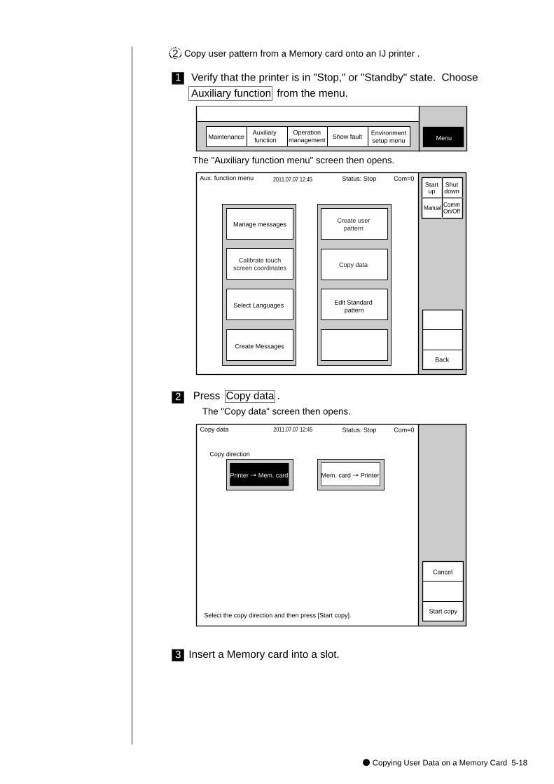
● Copying User Data on a Memory Card 5-18
1 Verify that the printer is in "Stop," or "Standby" state. Choose
Auxiliary function from the menu.
The "Auxiliary function menu" screen then opens.
MaintenanceAuxiliary function Show fault Menu
Operationmanagement
Environmentsetup menu
2011.07.07 12:45
Manage messagesCreate user
pattern
Calibrate touchscreen coordinates
Aux. function menu
Back
Manual
Status: Stop Com=0 Startup
Shutdown
CommOn/Off
Copy data
Edit Standard pattern
Select Languages
Create Messages
Copy user pattern from a Memory card onto an IJ printer .2
2011.07.07 12:45Copy data
Start copy
Copy direction
Printer → Mem. card Mem. card → Printer
Cancel
Select the copy direction and then press [Start copy].
Status: Stop Com=0
2 Press Copy data .
The "Copy data" screen then opens.
Insert a Memory card into a slot.3
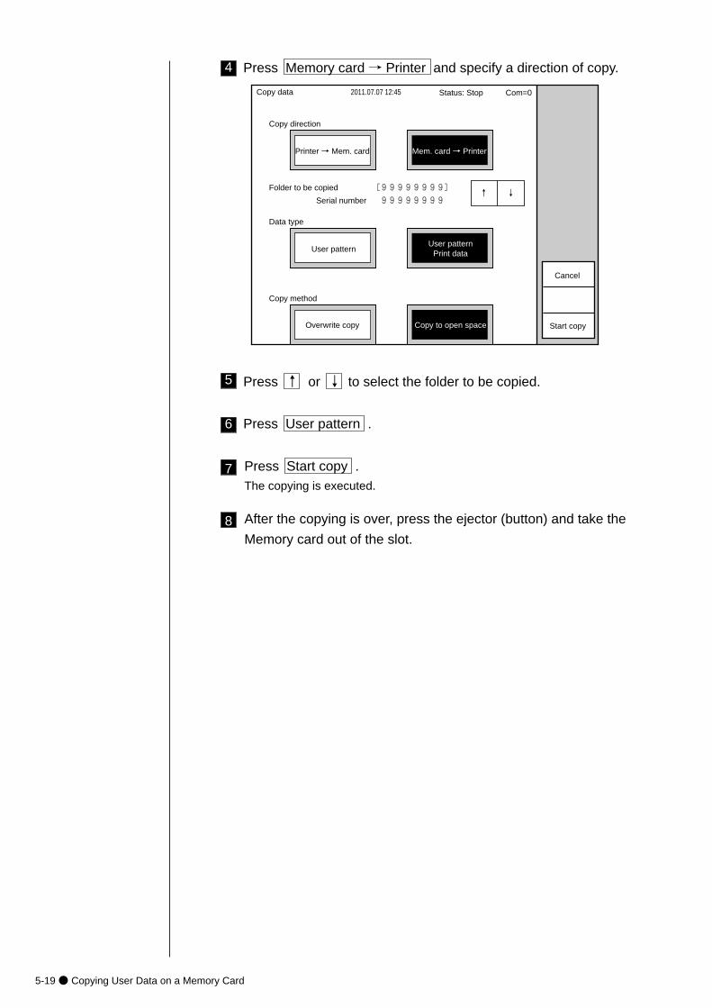
5-19● Copying User Data on a Memory Card
4 Press Memory card → Printer and specify a direction of copy.
5 Press ↑ or ↓ to select the folder to be copied.
6 Press User pattern .
7 Press Start copy .The copying is executed.
8 After the copying is over, press the ejector (button) and take the
Memory card out of the slot.
2011.07.07 12:45Copy data
Start copy
Copy direction
Printer → Mem. card Mem. card → Printer
Data type
Folder to be copied [99999999]�
Serial number 99999999�
User patternUser pattern
Print data
Copy method
Overwrite copy Copy to open space
Cancel
Status: Stop Com=0
↑� ↓�
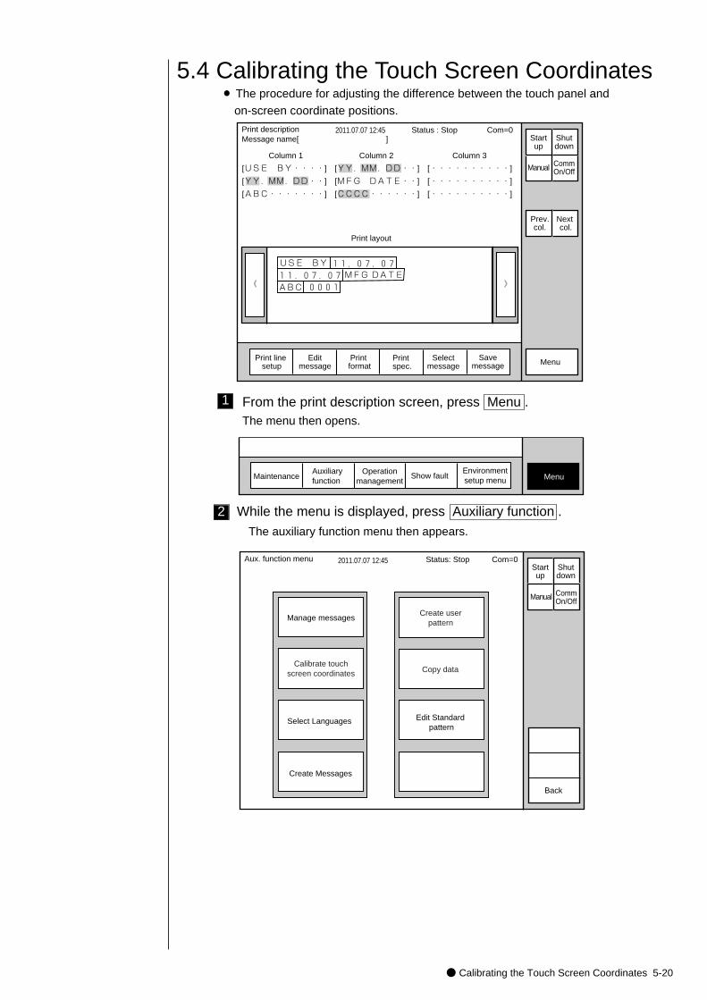
● Calibrating the Touch Screen Coordinates 5-20
1
5.4 Calibrating the Touch Screen Coordinates¡ The procedure for adjusting the difference between the touch panel and
on-screen coordinate positions.
》
Status : Stop Com=0
Column 1 Column 2 Column 3
[USE BY・・・・] [YY.MM.DD・・] [・・・・・・・・・・]
[YY.MM.DD・・] [MFG DATE・・] [・・・・・・・・・・]
[ABC・・・・・・・] [CCCC・・・・・・] [・・・・・・・・・・]
《
USE BY�MFG DATE�
ABC11.07.07
0001
11.07.07
Print descriptionMessage name[ ]
2011.07.07 12:45
Manual
Menu
Print layout
Prev.col.
Next col.
Startup
Shutdown
CommOn/Off
Selectmessage
Print line setup
Editmessage
Print format
Print spec.
Savemessage
From the print description screen, press Menu .The menu then opens.
MaintenanceAuxiliary function
Show fault MenuOperation
managementEnvironmentsetup menu
2011.07.07 12:45
Manage messagesCreate user
pattern
Calibrate touchscreen coordinates
Aux. function menu
Back
Manual
Status: Stop Com=0 Startup
Shutdown
CommOn/Off
Copy data
Select Languages Edit Standard pattern
Create Messages
2 While the menu is displayed, press Auxiliary function .
The auxiliary function menu then appears.
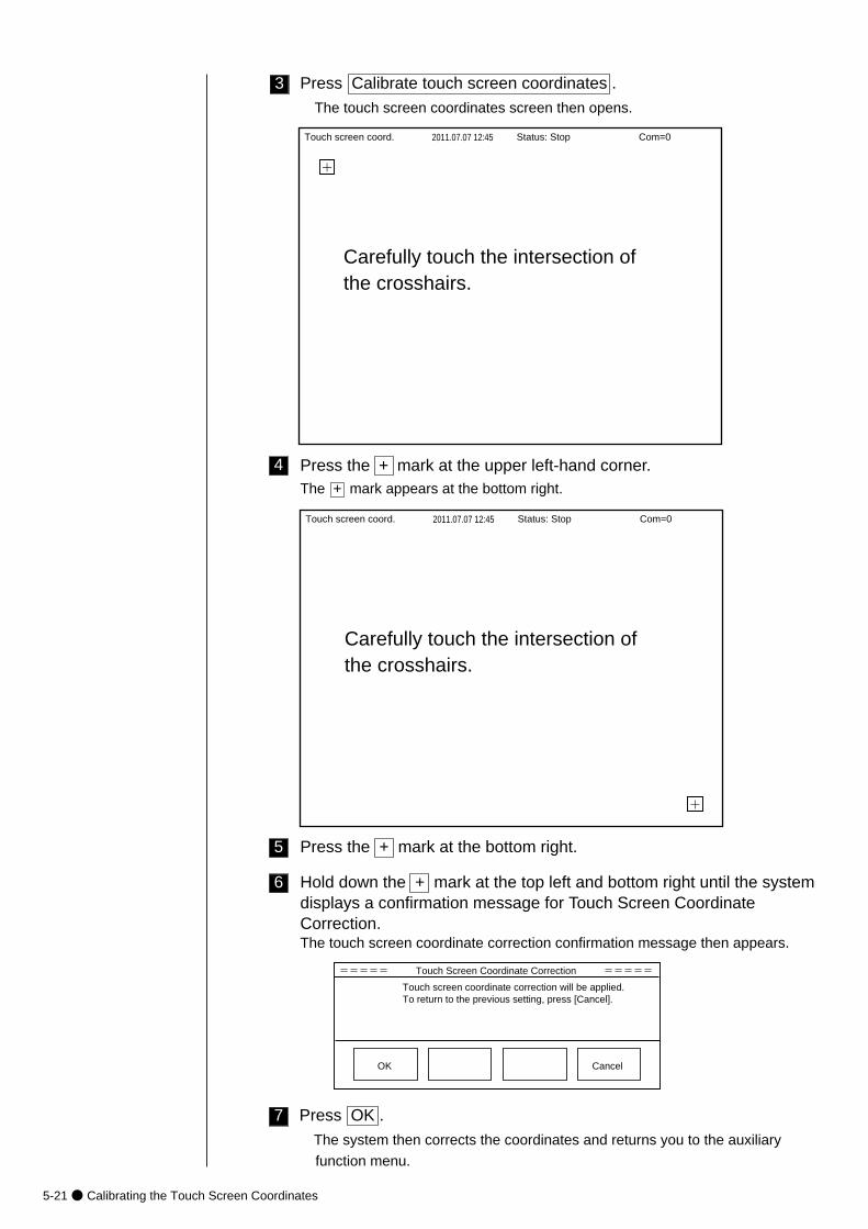
5-21● Calibrating the Touch Screen Coordinates
3
Status: Stop Com=0
+
Carefully touch the intersection ofthe crosshairs.
Touch screen coord. 2011.07.07 12:45
Press Calibrate touch screen coordinates .
The touch screen coordinates screen then opens.
4 Press the + mark at the upper left-hand corner.The + mark appears at the bottom right.
Status: Stop Com=0
+
Carefully touch the intersection ofthe crosshairs.
Touch screen coord. 2011.07.07 12:45
5 Press the + mark at the bottom right.
6 Hold down the + mark at the top left and bottom right until the systemdisplays a confirmation message for Touch Screen CoordinateCorrection. The touch screen coordinate correction confirmation message then appears.
7
===== Touch Screen Coordinate Correction =====
Touch screen coordinate correction will be applied. To return to the previous setting, press [Cancel].
OK Cancel
Press OK .
The system then corrects the coordinates and returns you to the auxiliary
function menu.

● Selecting Languages 5-22
(1) Overview
¡You can change the language of screen from English to another language.
(2) Operating procedure
¡Changing the language of screen from English to another language.
5.5 Selecting Languages
Maintenance Auxiliary function
Show fault MenuOperation
managementEnvironmentsetup menu
2011.07.07 12:45
Manage messagesCreate user
pattern
Calibrate touchscreen coordinates
Aux. function menu
Back
Manual
Status: Stop Com=0 Startup
Shutdown
CommOn/Off
Copy data
Select LanguagesEdit Standard
pattern
Create Messages
Select language Status : Stop Com=0
Back
OK
2011.07.07 12:45
�
Current language : English 01.00
Registered language
Language1 : English 01.00
Language2 : French 01.00
Press <OK> to change the language of screen.
�
�
↓
↑
Incre-ment
Decre-ment
1 Verify that the printer is in "Stop" state.
Choose Auxiliary function from the menu.
2 Press Select Languages .
The "Select language menu" screen then opens.
The "Auxiliary function menu" screen then opens.
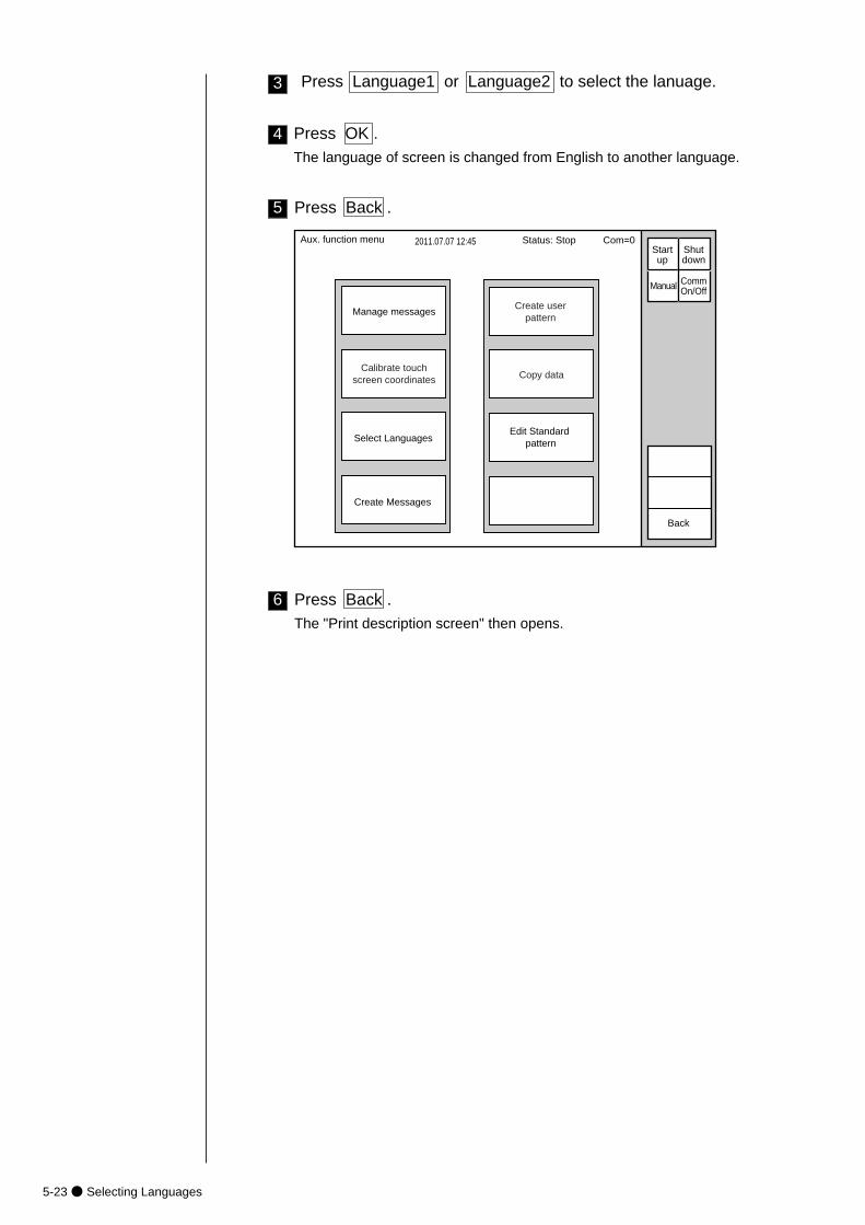
5-23● Selecting Languages
3 Press Language1 or Language2 to select the lanuage.
Press OK .The language of screen is changed from English to another language.
4
2011.07.07 12:45
Manage messagesCreate user
pattern
Calibrate touchscreen coordinates
Aux. function menu
Back
Manual
Status: Stop Com=0 Startup
Shutdown
CommOn/Off
Copy data
Select LanguagesEdit Standard
pattern
Create Messages
5 Press Back .
6 Press Back .The "Print description screen" then opens.
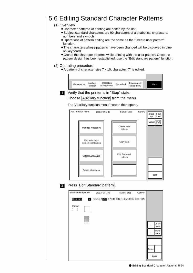
● Editing Standard Character Patterns 5-24
(1) Overview¡Character patterns of printing are edited by the dot.¡Subject standard characters are 90 characters of alphabetical characters,
numbers and symbols.¡Operations of pattern editing are the same as the "Create user pattern"
function.¡The characters whose patterns have been changed will be displayed in blue
on keyboard.¡Create the character patterns while printing with the user pattern: Once the
pattern design has been established, use the "Edit standard pattern" function.
(2) Operating procedure¡A pattern of character size 7 x 10, character "7" is edited.
5.6 Editing Standard Character Patterns
Maintenance Auxiliary function
Show fault MenuOperation
managementEnvironmentsetup menu
1 Verify that the printer is in "Stop" state.
Choose Auxiliary function from the menu.
The "Auxiliary function menu" screen then opens.
2011.07.07 12:45
Manage messagesCreate user
pattern
Calibrate touchscreen coordinates
Aux. function menu
Back
Manual
Status: Stop Com=0 Startup
Shutdown
CommOn/Off
Copy data
Select LanguagesEdit Standard
pattern
Create Messages
2 Press Edit Standard pattern .
Edit standard pattern 2011.07.07 12:45
Char. size [2](1:5×5 2:5×8 3:7×10 4:12×16 5:18×24 6:24×32)
Pattern
( )
Select
Back
Status: Stop Com=0
↓
↑
Incre-ment
Decre-ment
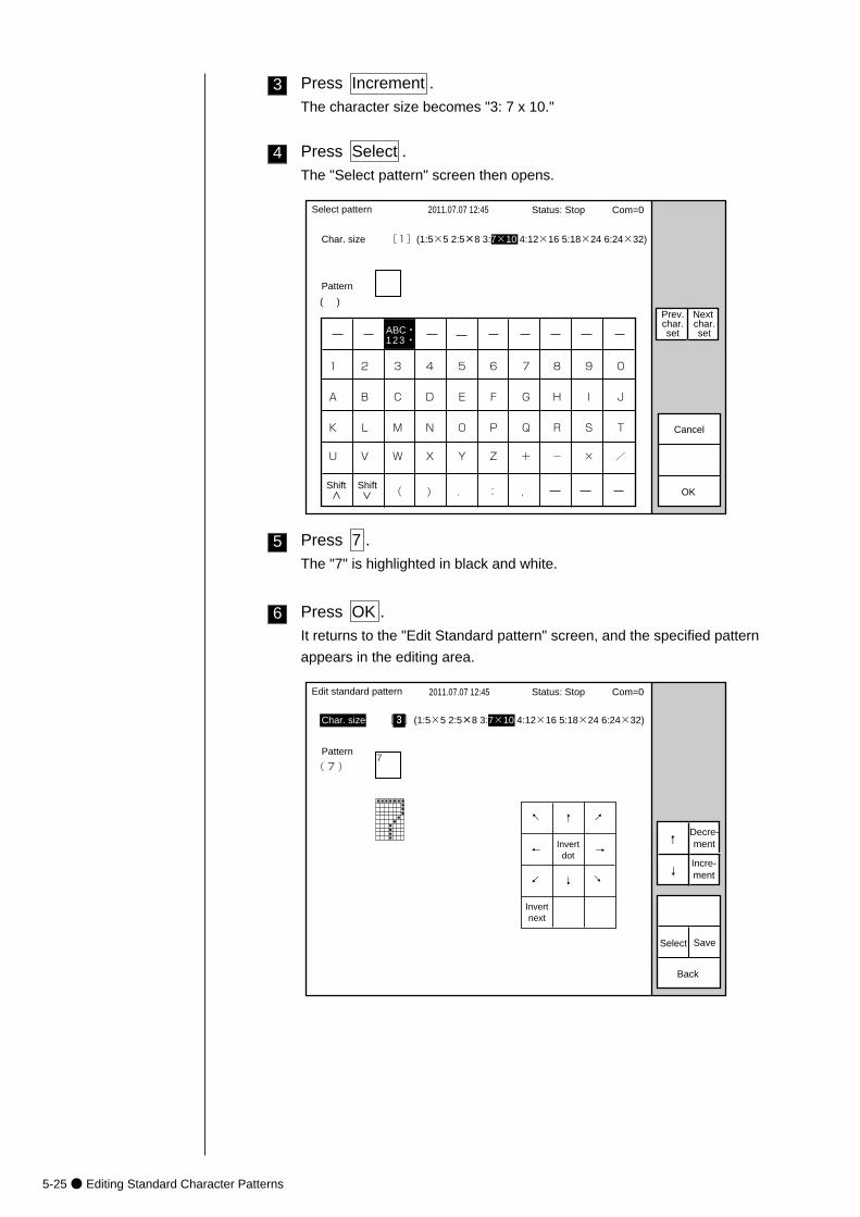
5-25● Editing Standard Character Patterns
3 Press Increment .The character size becomes "3: 7 x 10."
Select pattern 2011.07.07 12:45
Char. size [1](1:5×5 2:5×8 3:7×10 4:12×16 5:18×24 6:24×32)
Pattern
( )
OK
Cancel
Prev.char.set
Next char.set
Status: Stop Com=0
ABC・123・�
1
K�
U�
A�
2
L�
V�
B�
3
M�
W�
C�
4
N�
X�
D�
5
O�
Y�
E�
6
P�
Z�
F�
7
Q�
+�
G�
8
R�
-�
H�
9
S�
�
I�
0
T�
/�
J�
(� )� .� :� ,�Shift Shift
4 Press Select .The "Select pattern" screen then opens.
5 Press 7 .The "7" is highlighted in black and white.
6 Press OK .It returns to the "Edit Standard pattern" screen, and the specified pattern
appears in the editing area.
Edit standard pattern 2011.07.07 12:45
Char. size [3](1:5×5 2:5×8 3:7×10 4:12×16 5:18×24 6:24×32)
Pattern
( 7 )
Select
Back
Status: Stop Com=0
7
→
↓
↑
←
Invertnext
Invertdot
Save
→
↓
↑
←↓
↑
Incre-ment
Decre-ment
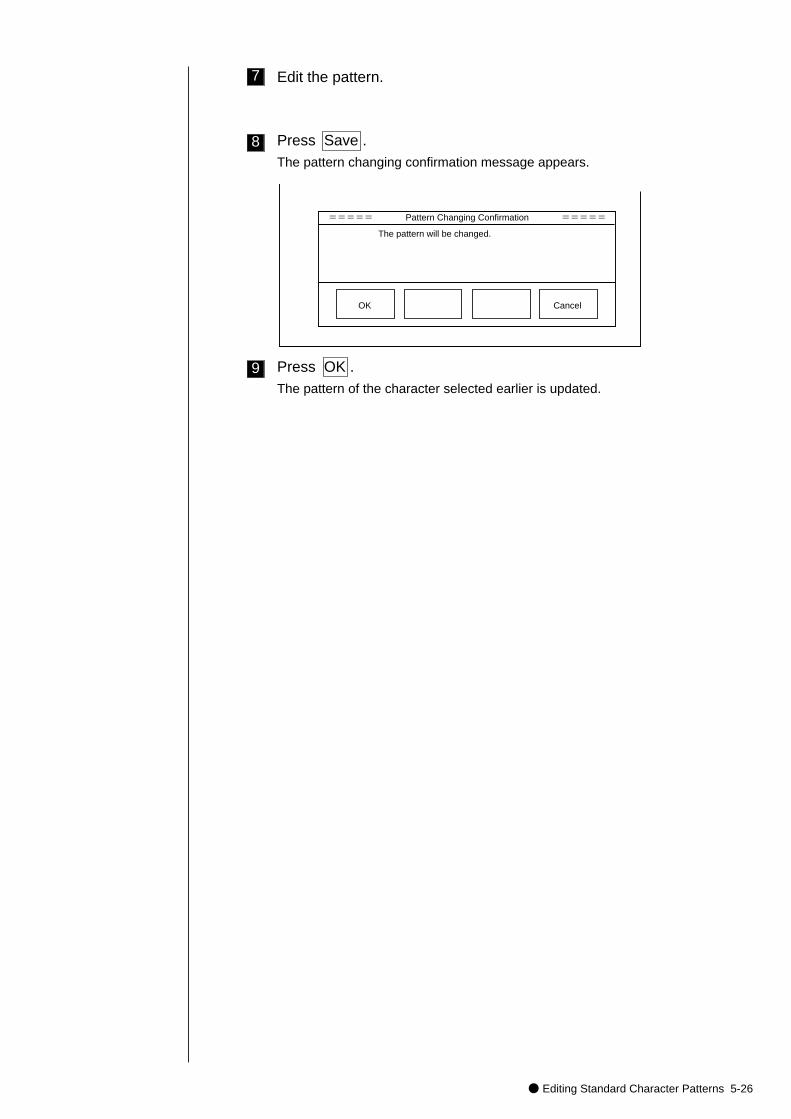
● Editing Standard Character Patterns 5-26
7 Edit the pattern.
8 Press Save .The pattern changing confirmation message appears.
===== Pattern Changing Confirmation =====
The pattern will be changed.
OK Cancel
9 Press OK .The pattern of the character selected earlier is updated.
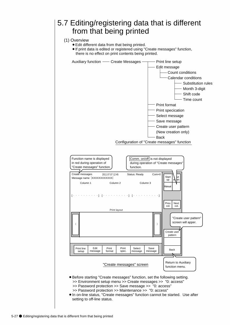
5-27● Editing/registering data that is different from that being printed
(1) Overview¡Edit different data from that being printed.¡If print data is edited or registered using "Create messages" function,
there is no effect on print contents being printed.
5.7 Editing/registering data that is different from that being printed
》《
Column 1 Column 2 Column 3
[・・・・・・・・・・] [・・・・・・・・・・] [・・・・・・・・・・]
Create messages 2011.07.07 12:45
Selectmessage
Message name[XXXXXXXXXXXX] Startup
Shutdown
Manual
Print line setup
Editmessage
Print format
Print spec.
Print layout
Status: Ready Com=0
Prev.col.
Next col.
Savemessage
Auxiliary function Create Messages Print line setupEdit message Count conditions Calendar conditions Substitution rules Month 3-digit Shift code Time countPrint formatPrint specicationSelect messageSave messageCreate user pattern (New creation only)Back
Configuration of "Create messages" function
Function name is displayed in red during operation of "Create messages" function.
"Create messages" screen
Back
"Create user pattern"screen will apper.
Create userpattern
Comm. on/off is not displayed during operation of "Create messages" function.
Return to Auxiliaryfunction menu.
¡Before starting "Create messages" function, set the following setting.>> Environment setup menu >> Create messages >> "0: access">> Password protection >> Save message >> "0: access" >> Password protection >> Maintenance >> "0: access"
¡In on-line status, "Create messages" function cannot be started. Use aftersetting to off-line status.
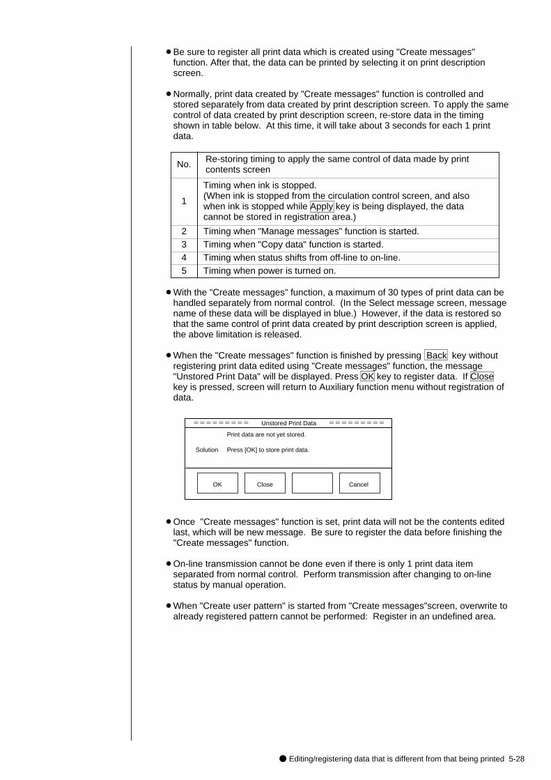
● Editing/registering data that is different from that being printed 5-28
¡Be sure to register all print data which is created using "Create messages"function. After that, the data can be printed by selecting it on print descriptionscreen.
¡Normally, print data created by "Create messages" function is controlled andstored separately from data created by print description screen. To apply the samecontrol of data created by print description screen, re-store data in the timingshown in table below. At this time, it will take about 3 seconds for each 1 printdata.
No. Re-storing timing to apply the same control of data made by print contents screen
1
Timing when ink is stopped.(When ink is stopped from the circulation control screen, and also when ink is stopped while Apply key is being displayed, the data cannot be stored in registration area.)
2 Timing when "Manage messages" function is started.3 Timing when "Copy data" function is started.4 Timing when status shifts from off-line to on-line.5 Timing when power is turned on.
¡With the "Create messages" function, a maximum of 30 types of print data can behandled separately from normal control. (In the Select message screen, messagename of these data will be displayed in blue.) However, if the data is restored sothat the same control of print data created by print description screen is applied,the above limitation is released.
¡When the "Create messages" function is finished by pressing Back key withoutregistering print data edited using "Create messages" function, the message"Unstored Print Data" will be displayed. Press OK key to register data. If Closekey is pressed, screen will return to Auxiliary function menu without registration ofdata.
========= Unstored Print Data =========�
Print data are not yet stored.
Solution Press [OK] to store print data.
OK Cancel Close
¡Once "Create messages" function is set, print data will not be the contents editedlast, which will be new message. Be sure to register the data before finishing the"Create messages" function.
¡On-line transmission cannot be done even if there is only 1 print data itemseparated from normal control. Perform transmission after changing to on-linestatus by manual operation.
¡When "Create user pattern" is started from "Create messages"screen, overwrite toalready registered pattern cannot be performed: Register in an undefined area.
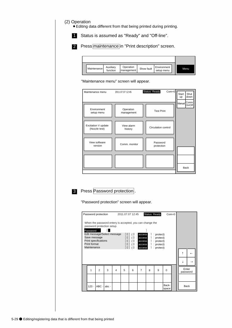
5-29● Editing/registering data that is different from that being printed
(2) Operation¡Editing data different from that being printed during printing.
Maintenance Auxiliary function
Show fault MenuOperation
managementEnvironmentsetup menu
Maintenance menu 2011.07.07 12:45
Environmentsetup menu
Operation management
Test Print
Excitation V update(Nozzle test)
View software version
View alarmhistory Circulation control
Passwordprotection
Comm. monitor
Back
Manual
Status: Ready Com=0 Startup
Shutdown
CommOn/Off
1 Status is assumed as "Ready" and "Off-line".
2 Press maintenance in "Print description" screen.
"Maintenance menu" screen will appear.
3 Press Password protection .
"Password protection" screen will appear.
[0](0: access 1:protect)[0](0: access 1:protect)[0](0: access 1:protect)[0](0: access 1:protect)[0](0: access 1:protect)
Password protection
PasswordEdit message/Select messageSave messagePrint specificationsPrint formatMaintenance
[ ]
When the password entery is accepted, you can change the password protection setup.
Enterpassword
2011.07.07 12:45
1 2 3 4 5 6 7 8 9 0
abc・�ABC・�123・� Back-space
Back
↓
↑
→
←
Status: Ready Com=0
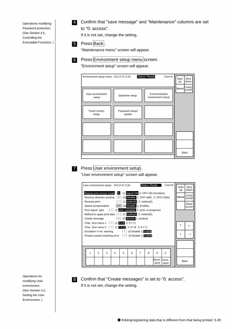
● Editing/registering data that is different from that being printed 5-30
4 Confirm that "save message" and "Maintenance" columns are set
to "0: access".If it is not set, change the setting.
5 Press Back ."Maintenance menu" screen will appear.
6 Press Environment setup menu screen."Environment setup" screen will appear.
Environment setup menu 2011.07.07 12:45
User environment setup
Date/time setupCommunication
environment setup
Touch screensetup
Password setup/update
Back
Manual
Startup
Shutdown
CommOn/Off
Status: Ready Com=0
7 Press User environment setup ."User environment setup" screen will appear.
1 2 3 4 5 6 7 8 9 0
User environment setup
Repeat print sensor mode[1](1: signal ON 2: OFF-ON transition)
Reverse direction printing [0](0: Disable 1: OFF=ABC 2: OFF=CBA)
Reverse print [1](1: method1 2: method2)
Speed compensation [0](0: Disable 1: Enable)
Print signal type [1](1:print. complete 2: print.-in-progress)
Method to apply print data[1](1: method1 2: method2)
Create message [0](0: access 1: protect)
2011.07.07 12:45
BackIncre-ment
Decre-ment
Manual
Showcursor
Startup
Shutdown
CommOn/Off
↑
↓
Status: Ready Com=0
Char. Size menu 1 [1](1: 5×8 2: 5×7)
Char. Size menu 2 [1](1: 7×10 2: 9×8 3: 9×7)
Excitation V-ref. warning [1](0:Disable 1:Enable)
Product speed matching error [1](0:Disable 1:Enable) →
←
8 Confirm that "Create messages" is set to "0: access". If it is not set, change the setting.
Operations modifying
Password protection.
(See Section 4.5,
Controlling the
Executable Functions. )
Operations for
modifying User
environment.
(See Section 4.2,
Setting the User
Environment. )
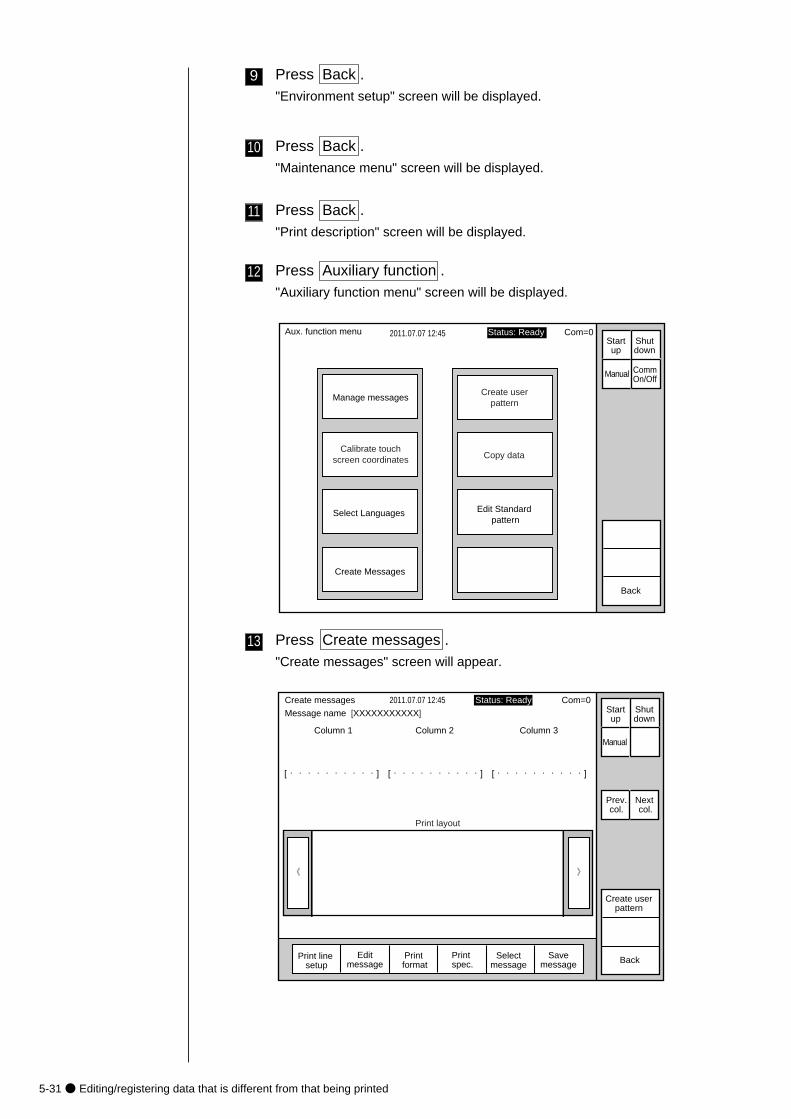
5-31● Editing/registering data that is different from that being printed
9 Press Back ."Environment setup" screen will be displayed.
10 Press Back ."Maintenance menu" screen will be displayed.
11 Press Back ."Print description" screen will be displayed.
12 Press Auxiliary function ."Auxiliary function menu" screen will be displayed.
2011.07.07 12:45
Manage messagesCreate user
pattern
Calibrate touchscreen coordinates
Aux. function menu
Back
Manual
Status: Ready Com=0 Startup
Shutdown
CommOn/Off
Copy data
Select Languages Edit Standard pattern
Create Messages
13 Press Create messages ."Create messages" screen will appear.
》《
Column 1 Column 2 Column 3
[・・・・・・・・・・] [・・・・・・・・・・] [・・・・・・・・・・]
Create messages 2011.07.07 12:45
Selectmessage
Message name [XXXXXXXXXXX] Startup
Shutdown
Manual
Print line setup
Editmessage
Print format
Print spec.
Print layout
Status: Ready Com=0
Prev.col.
Next col.
Savemessage Back
Create userpattern
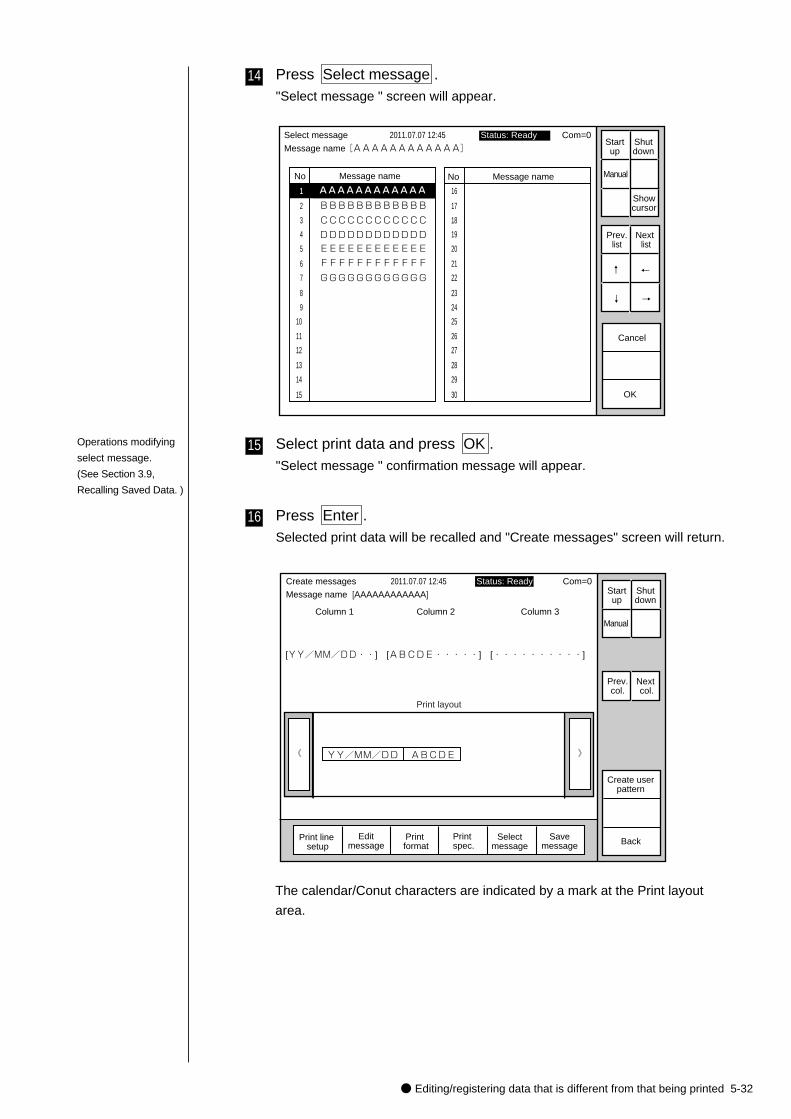
● Editing/registering data that is different from that being printed 5-32
14 Press Select message ."Select message " screen will appear.
No Message name
AAAAAAAAAAAA�
No Message name
1
2
3
4
5
6
7
8
9
10
11
12
13
14
15
Select message 2011.07.07 12:45
OK
16
17
18
19
20
21
22
23
24
25
26
27
28
29
30
BBBBBBBBBBBB
CCCCCCCCCCCC
DDDDDDDDDDDD
EEEEEEEEEEEE
FFFFFFFFFFFF
GGGGGGGGGGGG
Cancel
Message name[AAAAAAAAAAAA]
Prev.list
Next list
↓
↑
→
←
Status: Ready Com=0Startup
Shutdown
Manual
Showcursor
15 Select print data and press OK ."Select message " confirmation message will appear.
16 Press Enter .Selected print data will be recalled and "Create messages" screen will return.
》《
Column 1 Column 2 Column 3
[YY/MM/DD・・] [ABCDE・・・・・] [・・・・・・・・・・]
Create messages 2011.07.07 12:45
Selectmessage
Message name [AAAAAAAAAAAA] Startup
Shutdown
Manual
Print line setup
Editmessage
Print format
Print spec.
Print layout
Status: Ready Com=0
Prev.col.
Next col.
Savemessage Back
YY/MM/DD ABCDE
Create userpattern
Operations modifying
select message.
(See Section 3.9,
Recalling Saved Data. )
The calendar/Conut characters are indicated by a mark at the Print layout
area.

5-33● Editing/registering data that is different from that being printed
17 Press Edit message ."Edit message"screen will appear.
KanaArabicDedi-cated
Userpat-tern
Calendar/count
Punct. Insert Delete
K
U
A
L
V
B
M
W
C
N
X
D
O
Y
E
P
Z
F
Q
+
G
R
-
H
S
×
I
T
/
J
Space BlankBack-space( ) . : ,
Edit message
Column 1 Column 2 Column 3
2011.07.07 12:45
Back
Calendar conditions
Count conditions
1 2 3 4 5 6 7 8 9 0
ABC・123・�
Manual
Showcursor
Prev.col.
Next col.
↓
↑
→
←
Status: Ready Com=0 Message name [AAAAAAAAAAAA] Start
upShutdown
Shift Shift
[YY/MM/DD・・] [ABCDE・・・・・] [・・・・・・・・・・]
18 Press character key on keyboard.
19 Press Apply .
20 Press Back ."Create messages" screen will return.
》《
Column 1 Column 2 Column 3
[YY/MM/DD・・] [FGHJK・・・・・] [・・・・・・・・・・]
Create messages 2011.07.07 12:45
Selectmessage
Message name[AAAAAAAAAAAA] Startup
Shutdown
Manual
Print line setup
Editmessage
Print format
Print spec.
Print layout
Status: Ready Com=0
Prev.col.
Next col.
Savemessage Back
YY/MM/DD FGHJK
Create userpattern
Operations modifying
edit message.
(See Section 3.3,
Printing Characters. )
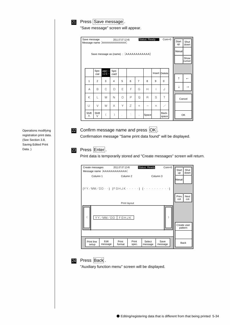
● Editing/registering data that is different from that being printed 5-34
21 Press Save message ."Save message" screen will appear.
Spe-cial Insert Delete
K
U
A
L
V
B
M
W
C
N
X
D
O
Y
E
P
Z
F
Q
+
G
R
-
H
S
×
I
T
/
J
SpaceBack-space( ) . : ,
Save message 2011.07.07 12:45
Cancel
1 2 3 4 5 6 7 8 9 0
ABC・123・�
OK
Save message as (name) :[AAAAAAAAAAAA]
↓
↑
→
←
Status: Ready Com=0 Message name[AAAAAAAAAAAA]
Shift Shift
Manual
Showcursor
Startup
Shutdown
Spe-cial2
22 Confirm message name and press OK .Confirmation message "Same print data found" will be displayed.
23 Press Enter .Print data is temporarily stored and "Create messages" screen will return.
》《
Column 1 Column 2 Column 3
[YY/MM/DD・・] [FGHJK・・・・・] [・・・・・・・・・・]
Create messages 2011.07.07 12:45
Selectmessage
Message name[AAAAAAAAAAAA] Startup
Shutdown
Manual
Print line setup
Editmessage
Print format
Print spec.
Print layout
Status: Ready Com=0
Prev.col.
Next col.
Savemessage Back
YY/MM/DD FGHJK
Create userpattern
24 Press Back ."Auxiliary function menu" screen will be displayed.
Operations modifying
registration print data.
(See Section 3.8,
Saving Edited Print
Data. )

5-35● Editing/registering data that is different from that being printed
25 Press Back ."Print description" screen will be displayed.
》《
Column 1 Column 2 Column 3
[USE BY ・・] [YY/MM/DD・・] [・・・・・・・・・・]
[MFG DATE・・] [YY/MM/DD・・] [・・・・・・・・・・]
Print description 2011.07.07 12:45
Selectmessage
Message name[BBBBBBBBBBBB] Startup
Shutdown
Manual
Print line setup
Editmessage
Print format
Print spec.
Print layout
Status: Ready Com=0
Prev.col.
Next col.
Savemessage Back
USE BY 11/10/06�
MFG DATE 11/07/07
Count reset
CommOn/Off
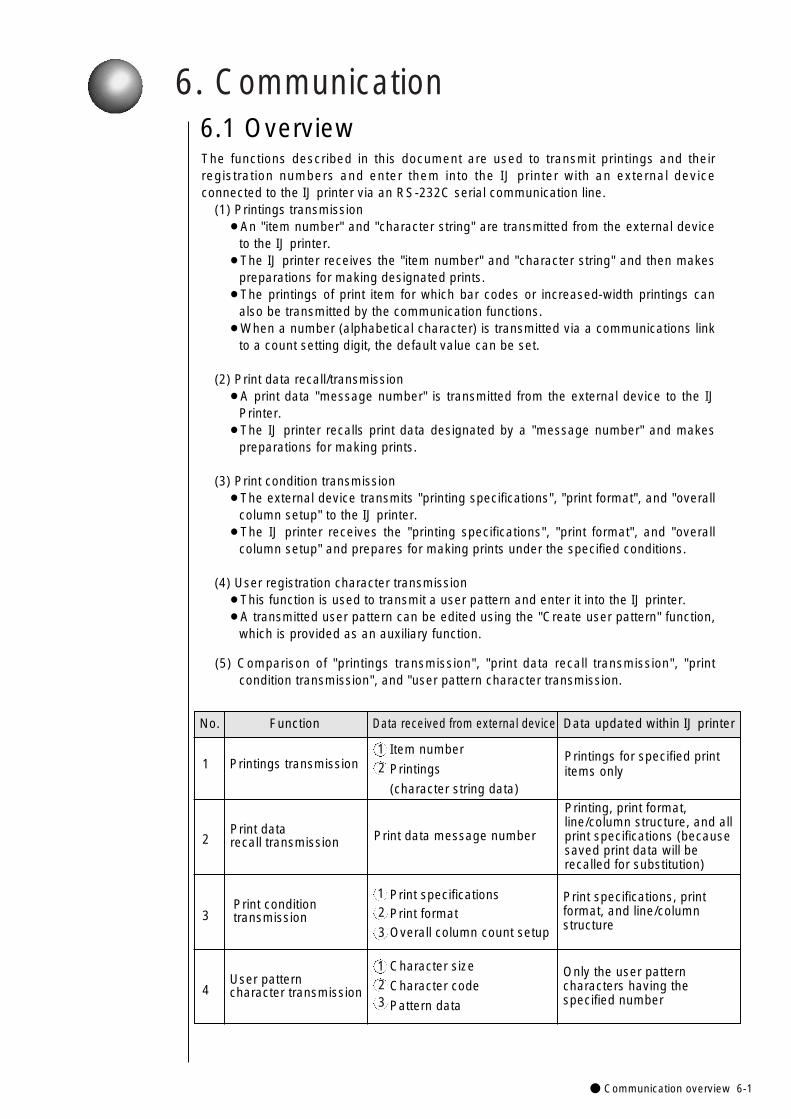
6. Communication
● Communication overview 6-1
The functions described in this document are used to transmit printings and theirregistration numbers and enter them into the IJ printer with an external deviceconnected to the IJ printer via an RS-232C serial communication line.
(1) Printings transmission¡An "item number" and "character string" are transmitted from the external device
to the IJ printer.¡The IJ printer receives the "item number" and "character string" and then makes
preparations for making designated prints.¡The printings of print item for which bar codes or increased-width printings can
also be transmitted by the communication functions.¡When a number (alphabetical character) is transmitted via a communications link
to a count setting digit, the default value can be set.
(2) Print data recall/transmission¡A print data "message number" is transmitted from the external device to the IJ
Printer.¡The IJ printer recalls print data designated by a "message number" and makes
preparations for making prints.
(3) Print condition transmission¡The external device transmits "printing specifications", "print format", and "overall
column setup" to the IJ printer.¡The IJ printer receives the "printing specifications", "print format", and "overall
column setup" and prepares for making prints under the specified conditions.
(4) User registration character transmission¡This function is used to transmit a user pattern and enter it into the IJ printer.¡A transmitted user pattern can be edited using the "Create user pattern" function,
which is provided as an auxiliary function.
(5) Comparison of "printings transmission", "print data recall transmission", "printcondition transmission", and "user pattern character transmission.
6.1 Overview
No. Function Data received from external device Data updated within IJ printer
1
2
3
4
Print datarecall transmission
Item number
Printings
(character string data)
Printings for specified print items only
Printing, print format, line/column structure, and allprint specifications (because saved print data will be recalled for substitution)
12
Print data message number
Printings transmission
Print specificationsPrint formatOverall column count setup
Print specifications, print format, and line/column structure
Print condition transmission
Character size
Character code
Pattern data
Only the user pattern characters having the specified number
User pattern character transmission
12
3
123
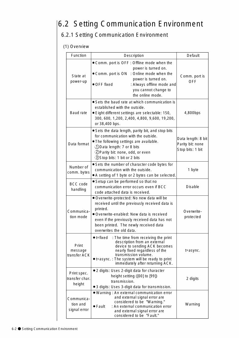
6-2● Setting Communication Environment
2 digits
Function Description
State atpower-up
Default
¡Comm. port is OFF : Offline mode when the power is turned on.
¡Comm. port is ON : Online mode when the power is turned on.
¡OFF fixed : Always offline mode and you cannot change to the online mode.
Comm. port isOFF
¡Sets the baud rate at which communication isestablished with the outside.
¡Eight different settings are selectable: 150,300, 600, 1,200, 2,400, 4,800, 9,600, 19,200,or 38,400 bps.
Baud rate 4,800bps
¡Sets the data length, parity bit, and stop bitsfor communication with the outside.
¡The following settings are available.Data length: 7 or 8 bitsParity bit: none, odd, or evenStop bits: 1 bit or 2 bits
Data formatData length: 8 bitParity bit: noneStop bits: 1 bit
6.2 Setting Communication Environment6.2.1 Setting Communication Environment
(1) Overview
Number ofcomm. bytes
¡Sets the number of character code bytes forcommunication with the outside.
¡A setting of 1 byte or 2 bytes can be selected.1 byte
BCC codehandling
¡Setup can be performed so that nocommunication error occurs even if BCCcode attached data is received.
Disable
123
Communica-tion mode
¡Overwrite-protected: No new data will bereceived until the previously received data isprinted.
¡Overwrite-enabled: New data is receivedeven if the previously received data has notbeen printed. The newly received dataoverwrites the old data.
Overwrite-protected
Printmessage
transfer ACK
¡t=fixed : The time from receiving the print description from an external device to sending ACK becomes nearly fixed regardless of the transmission volume.
¡t=async. : The system will be ready to print immediately after returning ACK.
t=async.
Print spec.transfer char.
height
¡2 digits: Uses 2-digit data for character height setting ([00] to [99]) transmission.
¡3 digits: Uses 3-digit data for transmission.
Communica-tion and
signal error
¡Warning : An external communication error and external signal error are considered to be "Warning."
¡Fault : An external communication error and external signal error are considered to be "Fault."
Warning
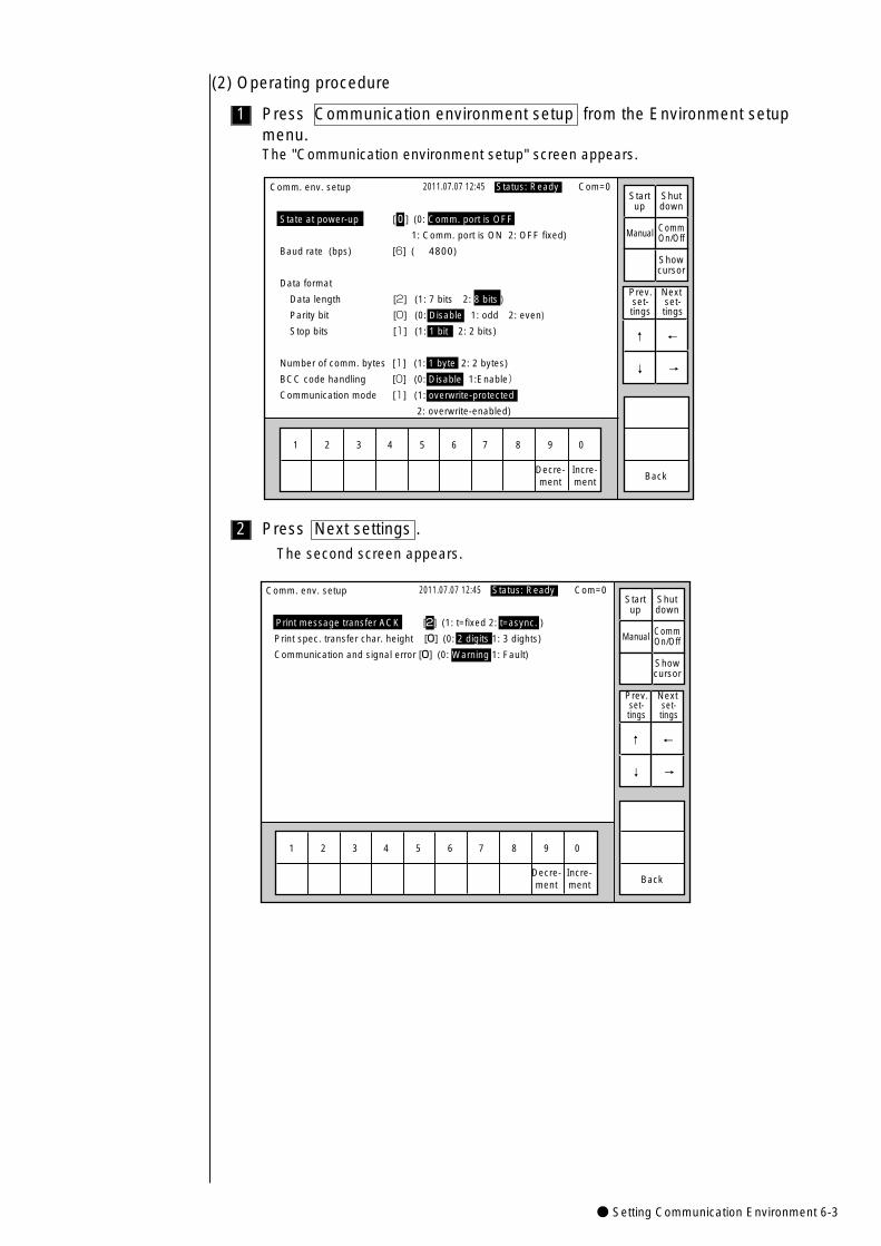
● Setting Communication Environment 6-3
1
(2) Operating procedure
Press Communication environment setup from the Environment setupmenu.The "Communication environment setup" screen appears.
Comm. env. setup 2011.07.07 12:45
State at power-up i[0] (0: Comm. port is OFF
1: Comm. port is ON 2: OFF fixed)
Baud rate (bps) i[6] ( 4800)
Data format
Data length i[2] (1: 7 bits 2: 8 bits )
Parity bit [0] (0: Disable 1: odd 2: even)
Stop bits [1] (1: 1 bit 2: 2 bits)
Number of comm. bytes [1] (1: 1 byte 2: 2 bytes)
BCC code handling [0] (0: Disable 1:Enable)
Communication mode [1] (1: overwrite-protected
2: overwrite-enabled)
1 2 3 4 5 6 7 8 9 0
BackIncre-ment
Decre-ment
Manual
Showcursor
Prev.set-tings
Next set-tings
↓
↑
Status: Ready Com=0 Startup
Shutdown
CommOn/Off
→
←
2 Press Next settings .
The second screen appears.
Comm. env. setup 2011.07.07 12:45
Print message transfer ACK [2] (1: t=fixed 2: t=async. )
Print spec. transfer char. height [0] (0: 2 digits 1: 3 dights)
Communication and signal error [0] (0: Warning 1: Fault)
1 2 3 4 5 6 7 8 9 0
BackIncre-ment
Decre-ment
Manual
Showcursor
Prev.set-tings
Next set-tings
↓
↑
Status: Ready Com=0Startup
Shutdown
CommOn/Off
→
←
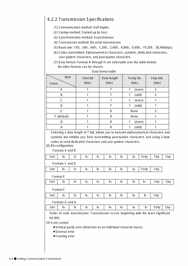
6-4● Setting Communication Environment
Start bit Data length Parity bit Stop bits
(bits) (bits) (bits) (bits)
Start b0 b1 b2 b3 b4 b5 b6 Parity Stop
6.2.2 Transmission Specifications
(1) Communication method: Half duplex
(2) Startup method: Started up by host
(3) Synchronization method: Asynchronous
(4) Transmission method: Bit serial transmission
(5) Baud rate: 150、300、600、1,200、2,400、4,800、9,600、19,200、38,400(bps)
(6) Codes transmitted: Alphanumerical characters, symbols, dedicated characters,
user pattern characters, and punctuation characters
(7) Data format: Formats A through H are selectable (see the table below).
No other formats can be chosen.
Data format table
A 1 7 1 (even) 2
B 1 7 1 (odd) 2
C 1 7 1 (even) 1
D 1 7 1 (odd) 1
E 1 8 None 2
F (default) 1 8 None 1
G 1 8 1 (even) 1
H 1 8 1 (odd) 1
Item
Format
Selecting a data length of 7 bits allows you to transmit alphanumerical characters and
symbols but inhibits you from transmitting punctuation characters and using 2-byte
codes to send dedicated characters and user pattern characters.(8) Bit configuration
Formats A and B
Start b0 b1 b2 b3 b4 b5 b6 Parity Stop Stop
Formats C and D
Format E
Start b0 b1 b2 b3 b4 b5 b6 b7 Stop Stop
Start b0 b1 b2 b3 b4 b5 b6 b7 Stop
Format F
Formats G and H
Start b0 b1 b2 b3 b4 b5 b6 b7 Parity Stop
Order of code transmission: Transmission occurs beginning with the least significant
bit (b0).
(9) Error control¡Vertical parity error (detection on an individual character basis)¡Overrun error¡Framing error
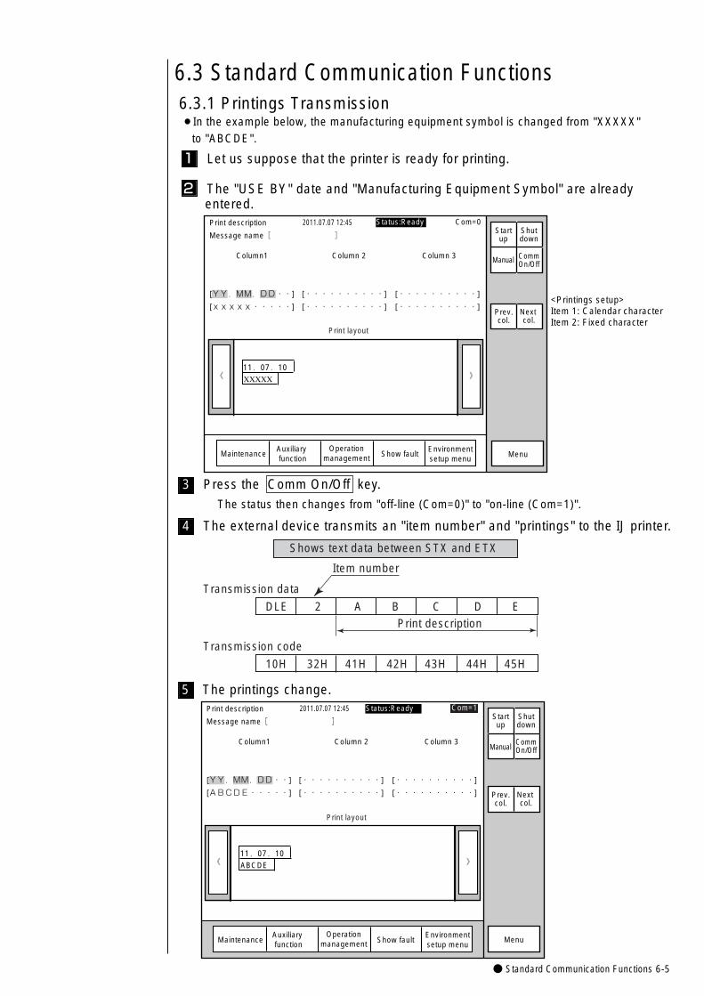
● Standard Communication Functions 6-5
6.3 Standard Communication Functions
》《 XXXXX11.07.10
Column1 Column 2 Column 3
[YY.MM.DD・・] [・・・・・・・・・・] [・・・・・・・・・・]
[xxxxx・・・・・] [・・・・・・・・・・] [・・・・・・・・・・]
Print description
Message name[ ]
2011.07.07 12:45
Manual
MaintenanceAuxiliary function
Show fault Menu
Prev.col.
Next col.
<Printings setup>Item 1: Calendar characterItem 2: Fixed character
Print layout
Status:Ready Com=0Startup
Shutdown
CommOn/Off
Operationmanagement
Environmentsetup menu
》《 ABCDE
11.07.10
Column1 Column 2 Column 3
[YY.MM.DD・・] [・・・・・・・・・・] [・・・・・・・・・・]
[ABCDE・・・・・] [・・・・・・・・・・] [・・・・・・・・・・]
Print description
Message name[ ]�
2011.07.07 12:45
Manual
MaintenanceAuxiliary function
Show fault Menu
Prev.col.
Next col.
�
�
�
Com=1
Print layout
Status:Ready Startup
Shutdown
CommOn/Off
Operationmanagement
Environmentsetup menu
6.3.1 Printings Transmission¡In the example below, the manufacturing equipment symbol is changed from "XXXXX"
to "ABCDE".
1 Let us suppose that the printer is ready for printing.
2 The "USE BY" date and "Manufacturing Equipment Symbol" are already entered.
5 The printings change.
Shows text data between STX and ETX
DLE 2 A B C D E
Transmission data
Item number
Print description
10H 32H 41H 42H 43H 44H 45H
Transmission code
3 Press the Comm On/Off key.
The status then changes from "off-line (Com=0)" to "on-line (Com=1)".
4 The external device transmits an "item number" and "printings" to the IJ printer.
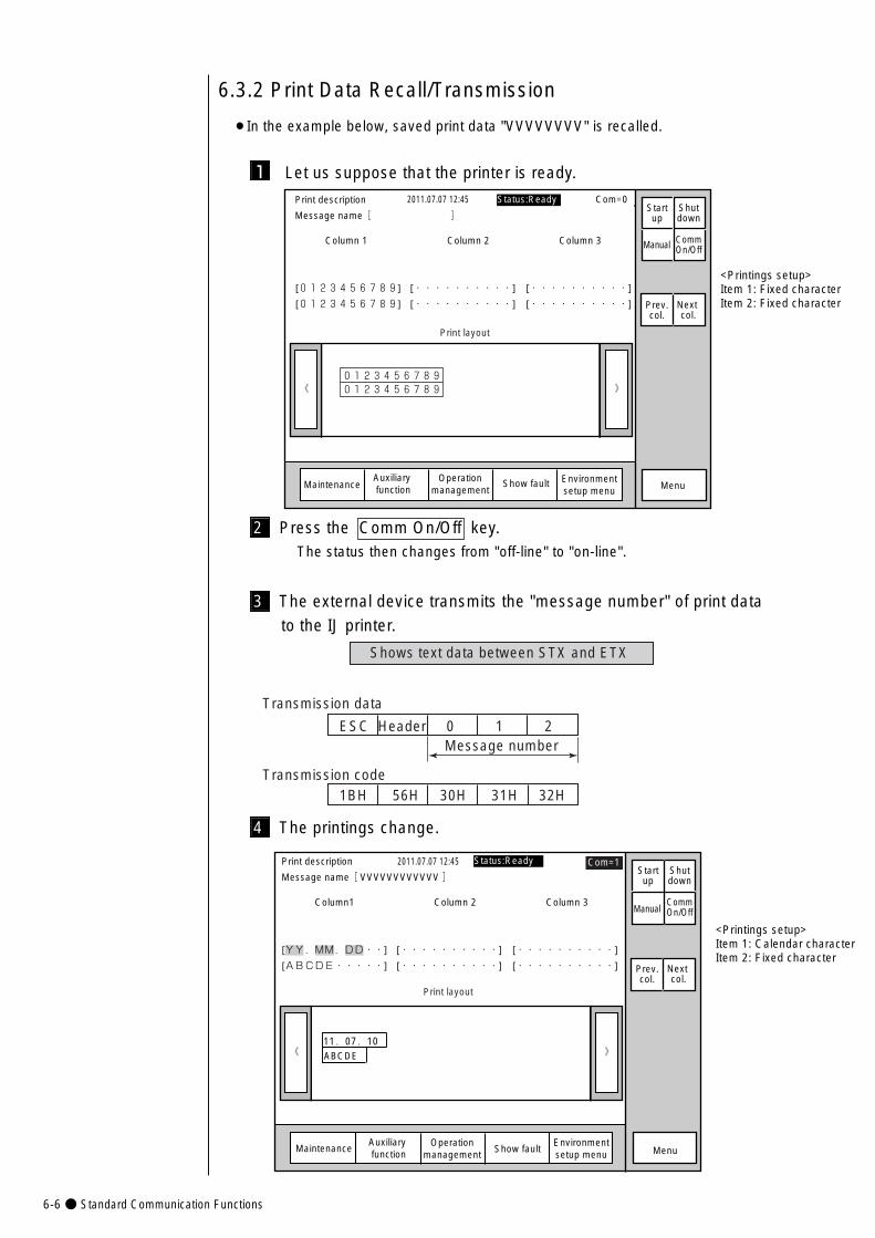
6-6● Standard Communication Functions
6.3.2 Print Data Recall/Transmission
¡In the example below, saved print data "VVVVVVVV" is recalled.
1 Let us suppose that the printer is ready.
》
Column 1 Column 2 Column 3
[0123456789] [・・・・・・・・・・] [・・・・・・・・・・]
[0123456789] [・・・・・・・・・・] [・・・・・・・・・・]
《 01234567890123456789
<Printings setup>Item 1: Fixed characterItem 2: Fixed character
Print description
Message name[ ]�
2011.07.07 12:45
Manual
MaintenanceAuxiliary function
Show fault Menu
Prev.col.
Next col.
Print layout
Status:Ready Com=0Startup
Shutdown
CommOn/Off
Operationmanagement
Environmentsetup menu
<Printings setup>Item 1: Calendar characterItem 2: Fixed character
》《 ABCDE
11.07.10
Column1 Column 2 Column 3
[YY.MM.DD・・] [・・・・・・・・・・] [・・・・・・・・・・]
[ABCDE・・・・・] [・・・・・・・・・・] [・・・・・・・・・・]
Print description
Message name[ VVVVVVVVVVVV ]�
2011.07.07 12:45
Manual
MaintenanceAuxiliary function Show fault Menu
Prev.col.
Next col.
�
�
�
Com=1
Print layout
Status:Ready Startup
Shutdown
CommOn/Off
Operationmanagement
Environmentsetup menu
2 Press the Comm On/Off key.The status then changes from "off-line" to "on-line".
3 The external device transmits the "message number" of print data
to the IJ printer.
4 The printings change.
Shows text data between STX and ETX
ESC Header 0 1 2
Transmission data
Message number
1BH 56H 30H 31H 32HTransmission code
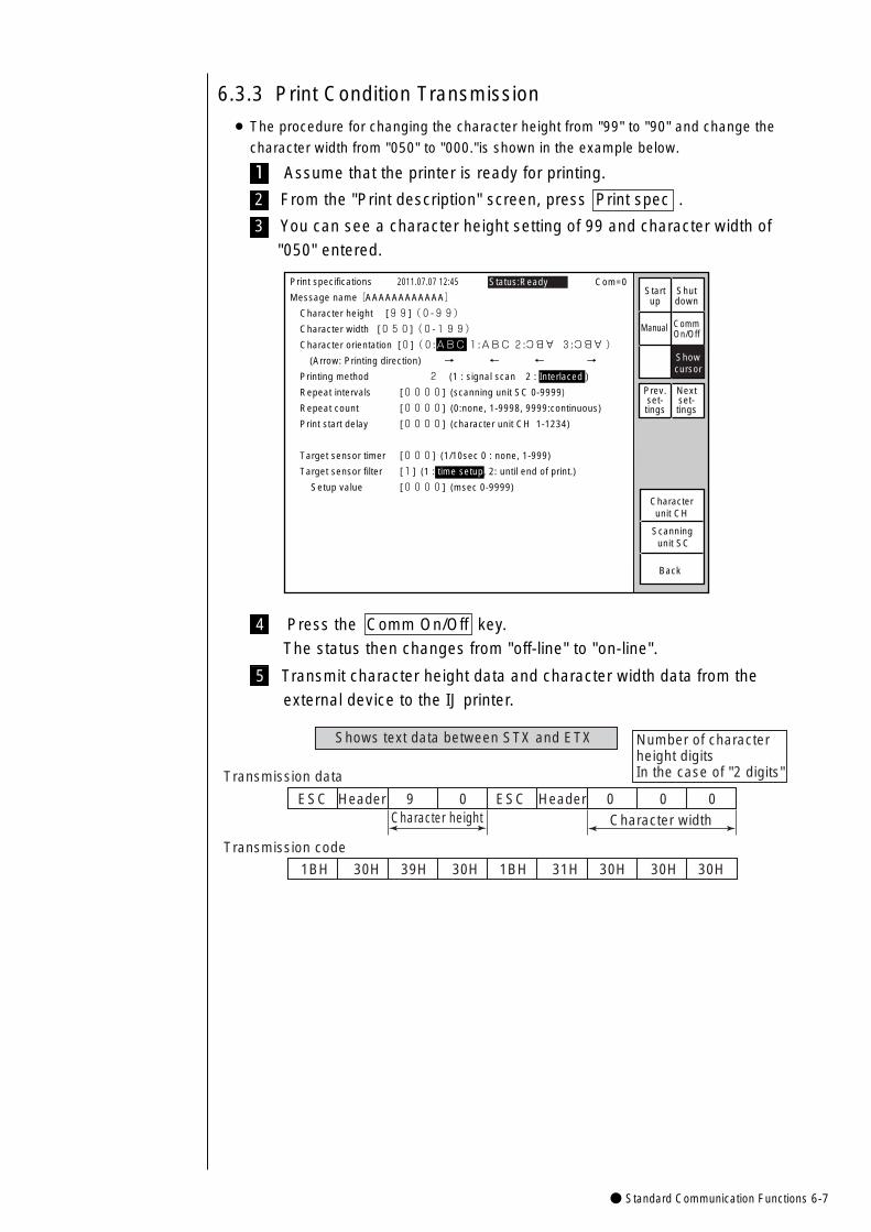
● Standard Communication Functions 6-7
6.3.3 Print Condition Transmission
¡ The procedure for changing the character height from "99" to "90" and change the
character width from "050" to "000."is shown in the example below.
1 Assume that the printer is ready for printing.
2 From the "Print description" screen, press Print spec .
3 You can see a character height setting of 99 and character width of
"050" entered.
Status:Ready Com=0Print specifications 2011.07.07 12:45
Back
Scanning unit SC
Characterunit CH
ABC ABC
Message name[AAAAAAAAAAAA]
Character height [99](0-99)
Character width [050](0-199)
Character orientation [0](0:ABC 1:ABC 2: 3: )
(Arrow: Printing direction) → ← ← →
Printing method 2 (1 : signal scan 2 : Interlaced )
Repeat intervals [0000] (scanning unit SC 0-9999)
Repeat count [0000] (0:none, 1-9998, 9999:continuous)
Print start delay [0000] (character unit CH 1-1234)
Target sensor timer [000] (1/10sec 0 : none, 1-999)
Target sensor filter [1] (1 : time setup, 2: until end of print.)
Setup value [0000] (msec 0-9999)
Manual
Showcursor
Startup
Shutdown
Prev.set-tings
Nextset-tings
CommOn/Off
4 Press the Comm On/Off key.
The status then changes from "off-line" to "on-line".
5 Transmit character height data and character width data from the
external device to the IJ printer.
Shows text data between STX and ETX
ESC Header 9 0 ESC Header 0 0 0
Transmission data
Character height
1BH 30H 39H 30H 1BH 31H 30H 30H 30H
Transmission code
Character width
Number of character height digitsIn the case of "2 digits"
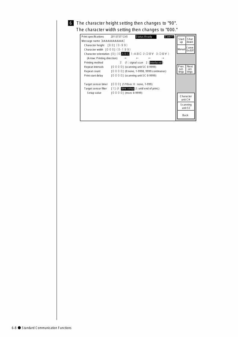
6-8● Standard Communication Functions
Status:Ready Com=1Print specifications 2011.07.07 12:45
Back
Scanning unit SC
Characterunit CH
ABC ABC
Manual
Message name[AAAAAAAAAAAA]
Character height [90](0-99)
Character width [000](0-199)
Character orientation [0](0:ABC 1:ABC 2: 3: )
(Arrow: Printing direction) → ← ← →
Printing method 2 (1 : signal scan 2 : Interlaced )
Repeat intervals [0000] (scanning unit SC 0-9999)
Repeat count [0000] (0:none, 1-9998, 9999:continuous)
Print start delay [0000] (scanning unit SC 0-9999)
Target sensor timer [000] (1/10sec 0 : none, 1-999)
Target sensor filter [1] (1 : time setup 2: until end of print.)
Setup value [0000] (msec 0-9999)
Startup
Shutdown
CommOn/Off
Prev.set-tings
Nextset-tings
6 The character height setting then changes to "90".
The character width setting then changes to "000."
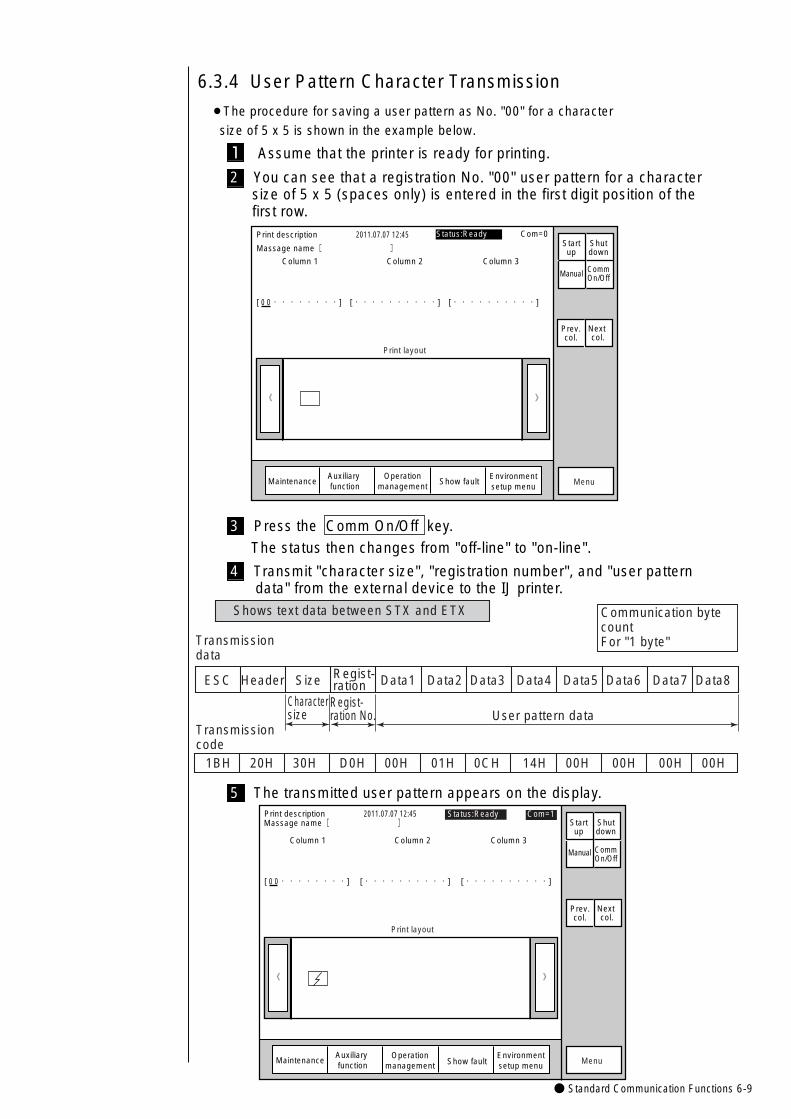
● Standard Communication Functions 6-9
》
Print description
Massage name[ ]�
Column 1 Column 2 Column 3
[ 0 0・・・・・・・・] [・・・・・・・・・・] [・・・・・・・・・・] �
2011.07.07 12:45
《
Print layout
Menu
Manual
Prev.col.
Next col.
MaintenanceAuxiliary function
Show fault
Status:Ready Com=0Startup
Shutdown
CommOn/Off
Operationmanagement
Environmentsetup menu
》
Print description
Column 1 Column 2 Column 3
[ 0 0・・・・・・・・] [・・・・・・・・・・] [・・・・・・・・・・]
2011.07.07 12:45
《
Print layout
Menu
Manual
Prev.col.
Next col.
MaintenanceAuxiliary function Show fault
Status:Ready Com=1Startup
Shutdown
CommOn/Off
Operationmanagement
Environmentsetup menu
Massage name[ ]�
6.3.4 User Pattern Character Transmission
¡The procedure for saving a user pattern as No. "00" for a character
size of 5 x 5 is shown in the example below.
1 Assume that the printer is ready for printing.
2 You can see that a registration No. "00" user pattern for a character size of 5 x 5 (spaces only) is entered in the first digit position of the first row.
4 Transmit "character size", "registration number", and "user pattern data" from the external device to the IJ printer.
5 The transmitted user pattern appears on the display.
Shows text data between STX and ETX
ESC Header Size Data1 Data2 Data3 Data4 Data5 Data6 Data7 Data8
Character size
1BH 20H 30H D0H 00H 01H 0CH 14H 00H 00H 00H 00H
Transmission code
Communication bytecountFor "1 byte"
Regist-ration
Regist-ration No. User pattern data
Transmission data
3 Press the Comm On/Off key.
The status then changes from "off-line" to "on-line".
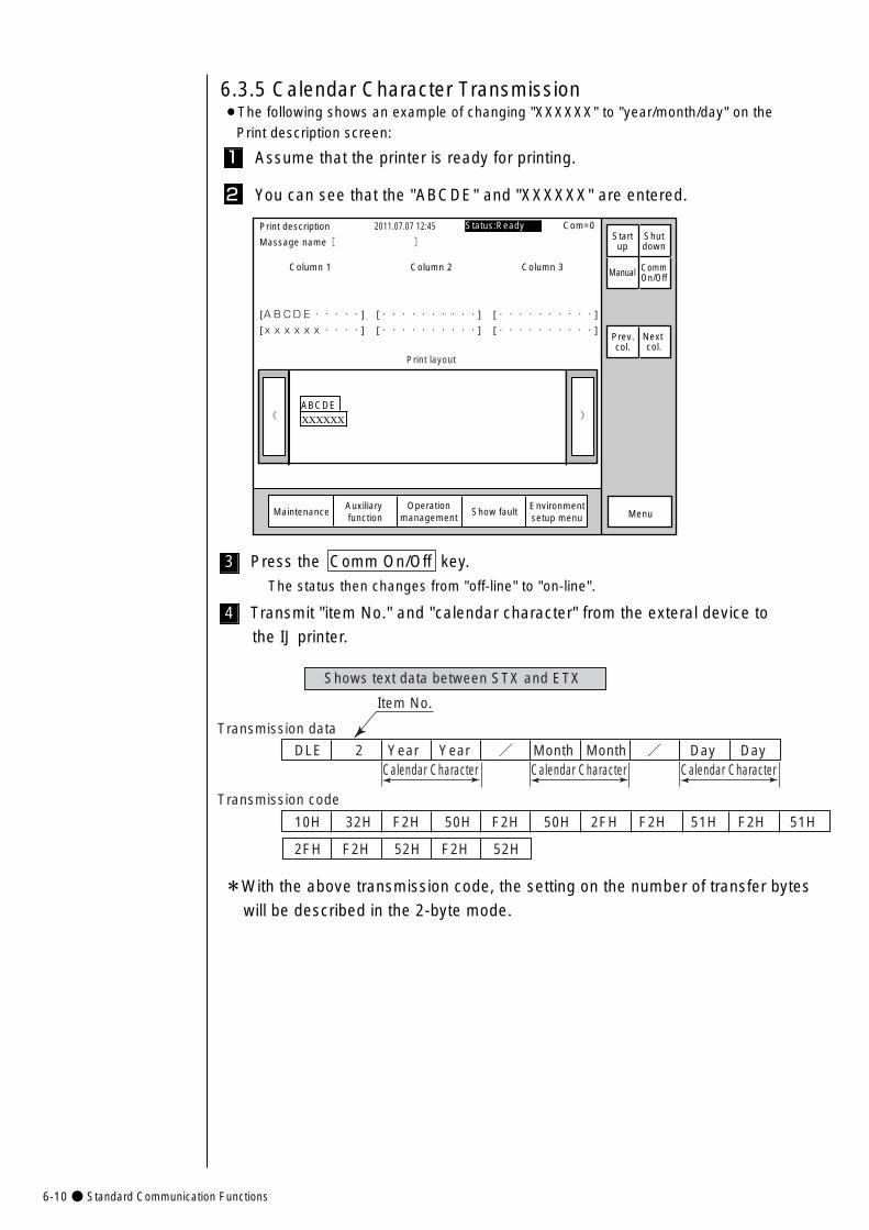
6-10● Standard Communication Functions
Shows text data between STX and ETX
DLE 2 Year Year / Month Month / Day Day
Transmission data
Item No.
Calendar Character Calendar Character Calendar Character
2FH F2H 52H F2H 52H
Transmission code
10H 32H F2H 50H F2H 50H 2FH F2H 51H F2H 51H
3 Press the Comm On/Off key.
The status then changes from "off-line" to "on-line".
4 Transmit "item No." and "calendar character" from the exteral device to
the IJ printer.
*With the above transmission code, the setting on the number of transfer bytes
will be described in the 2-byte mode.
》《 XXXXXXABCDE
Column 1 Column 2 Column 3
[ABCDE・・・・・] [・・・・・・・・・・] [・・・・・・・・・・]
[xxxxxx・・・・] [・・・・・・・・・・] [・・・・・・・・・・]
Print description
Massage name[ ]�
2011.07.07 12:45
Manual
MaintenanceAuxiliary function
Show fault Menu
Prev.col.
Next col.
Print layout
Status:Ready Com=0Startup
Shutdown
CommOn/Off
Operationmanagement
Environmentsetup menu
6.3.5 Calendar Character Transmission¡The following shows an example of changing "XXXXXX" to "year/month/day" on the
Print description screen:
1 Assume that the printer is ready for printing.
2 You can see that the "ABCDE" and "XXXXXX" are entered.
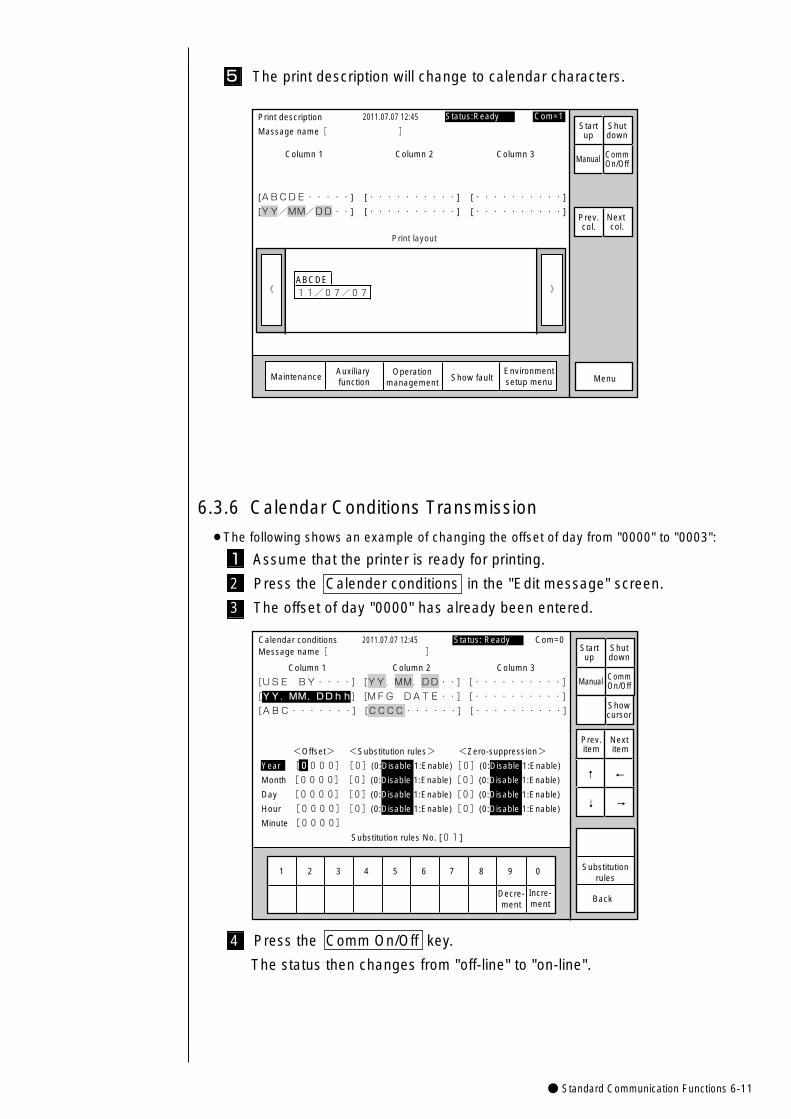
● Standard Communication Functions 6-11
》《 11/07/07�ABCDE
Column 1 Column 2 Column 3
[ABCDE・・・・・] [・・・・・・・・・・] [・・・・・・・・・・]
[YY/MM/DD・・] [・・・・・・・・・・] [・・・・・・・・・・]
Print description
Massage name[ ]�
2011.07.07 12:45
Manual
MaintenanceAuxiliary function Show fault Menu
Prev.col.
Next col.
Print layout
Status:Ready Com=1Startup
Shutdown
CommOn/Off
Operationmanagement
Environmentsetup menu
5 The print description will change to calendar characters.
6.3.6 Calendar Conditions Transmission
¡The following shows an example of changing the offset of day from "0000" to "0003":
1 Assume that the printer is ready for printing.
2 Press the Calender conditions in the "Edit message" screen.
3 The offset of day "0000" has already been entered.
1 2 3 4 5 6 7 8 9 0
Incre-ment
Decre-ment
Calendar conditions
Column 1 Column 2 Column 3
[USE BY・・・・] [YY.MM.DD・・] [・・・・・・・・・・] �
[YY.MM.DDhh] [MFG DATE・・] [・・・・・・・・・・] �
[ABC・・・・・・・] [CCCC・・・・・・] [・・・・・・・・・・]
2011.07.07 12:45
Back
<Offset> <Substitution rules> <Zero-suppression>
Year [0000][0](0:Disable 1:Enable)[0](0:Disable 1:Enable)
Month [0000][0](0:Disable 1:Enable)[0](0:Disable 1:Enable)
Day [0000][0](0:Disable 1:Enable)[0](0:Disable 1:Enable)
Hour [0000][0](0:Disable 1:Enable)[0](0:Disable 1:Enable)
Minute [0000]�
Substitution rules No. [01]
Manual
Showcursor
Prev.item
Next item
↓
↑
→
←
Status: Ready Com=0
Substitutionrules
Message name[ ] Startup
Shutdown
CommOn/Off
4 Press the Comm On/Off key.
The status then changes from "off-line" to "on-line".
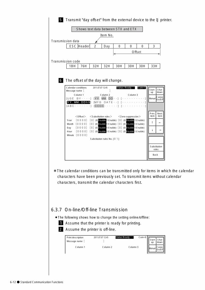
6-12● Standard Communication Functions
Calendar conditions
Column 1 Column 2 Column 3
[USE BY・・・・] [YY.MM.DD・・] [・・・・・・・・・・] �
[YY.MM.DDhh] [MFG DATE・・] [・・・・・・・・・・] �
[ABC・・・・・・・] [CCCC・・・・・・] [・・・・・・・・・・]
2011.07.07 12:45
Back
<Offset> <Substitution rules> <Zero-suppression>
Year [0000][0](0:Disable 1:Enable)[0](0:Disable 1:Enable)
Month [0000][0](0:Disable 1:Enable)[0](0:Disable 1:Enable)
Day [0003][0](0:Disable 1:Enable)[0](0:Disable 1:Enable)
Hour [0000][0](0:Disable 1:Enable)[0](0:Disable 1:Enable)
Minute [0000]�
Substitution rules No. [01]
Prev.item
Next item
↓
↑
→
←
Status: Ready Com=1
Substitutionrules
Message name[ ]
Manual
Startup
Shutdown
CommOn/Off
6 The offset of the day will change.
*The calendar conditions can be transmitted only for items in which the calendar
characters have been previously set. To transmit items without calendar
characters, transmit the calendar characters first.
6.3.7 On-line/Off-line Transmission
¡The following shows how to change the setting online/offline:
1 Assume that the printer is ready for printing.
2 Assume the printer is off-line.
Column 1 Column 2 Column 3
Print description
Message name[ ]�
2011.07.07 12:45
Manual
Status:Ready Com=0Startup
Shutdown
CommOn/Off
Shows text data between STX and ETX
1BH 76H 32H 32H 30H 30H 30H 33H
Offset
ESC Header 2 Day 0 0 0 3
Transmission data
Transmission code
Item No.
5 Transmit "day offset" from the external device to the IJ printer.
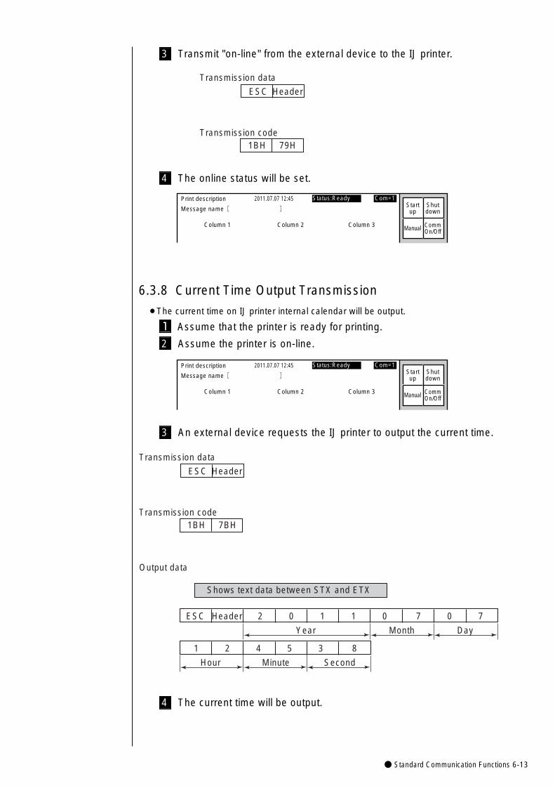
● Standard Communication Functions 6-13
1BH 79H
ESC Header
Transmission data
Transmission code
3 Transmit "on-line" from the external device to the IJ printer.
4 The online status will be set.
Column 1 Column 2 Column 3
Print description
Message name[ ]�
2011.07.07 12:45
Manual
Status:Ready Com=1Startup
Shutdown
CommOn/Off
6.3.8 Current Time Output Transmission
¡The current time on IJ printer internal calendar will be output.
1 Assume that the printer is ready for printing.
2 Assume the printer is on-line.
Column 1 Column 2 Column 3
Print description
Message name[ ]�
2011.07.07 12:45
Manual
Status:Ready Com=1Startup
Shutdown
CommOn/Off
Shows text data between STX and ETX
ESC Header 2 0 1 1 0 7 0 7
Year Month Day
1 2 4 5 3 8
Hour Minute Second
1BH 7BH
ESC Header
Transmission data
Output data
Transmission code
3 An external device requests the IJ printer to output the current time.
4 The current time will be output.
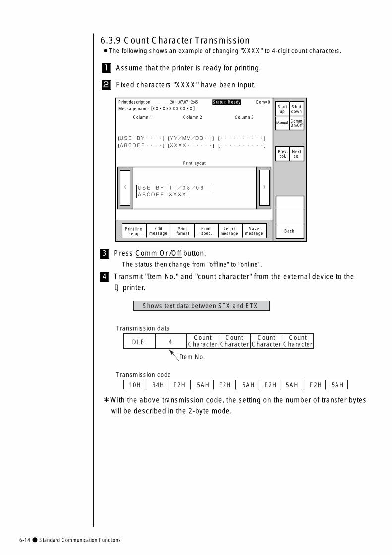
6-14● Standard Communication Functions
Shows text data between STX and ETX
DLE 4
Transmission data
Item No.
Transmission code
10H 34H F2H 5AH F2H 5AH F2H 5AH F2H 5AH
CountCharacter
CountCharacter
CountCharacter
CountCharacter
3 Press Comm On/Off button.
The status then change from "offline" to "online".
4 Transmit "Item No." and "count character" from the external device to the
IJ printer.
*With the above transmission code, the setting on the number of transfer bytes
will be described in the 2-byte mode.
》《
Column 1 Column 2 Column 3
[USE BY・・・・] [YY/MM/DD・・] [・・・・・・・・・・]
[ABCDEF・・・・] [XXXX・・・・・・] [・・・・・・・・・・]
Print description 2011.07.07 12:45
Selectmessage
Message name[XXXXXXXXXXXX] Startup
Shutdown
Manual
Print line setup
Editmessage
Print format
Print spec.
Print layout
Status: Ready Com=0
Prev.col.
Next col.
Savemessage Back
USE BY 11/08/06�ABCDEF XXXX�
CommOn/Off
6.3.9 Count Character Transmission¡The following shows an example of changing "XXXX" to 4-digit count characters.
1 Assume that the printer is ready for printing.
2 Fixed characters "XXXX" have been input.
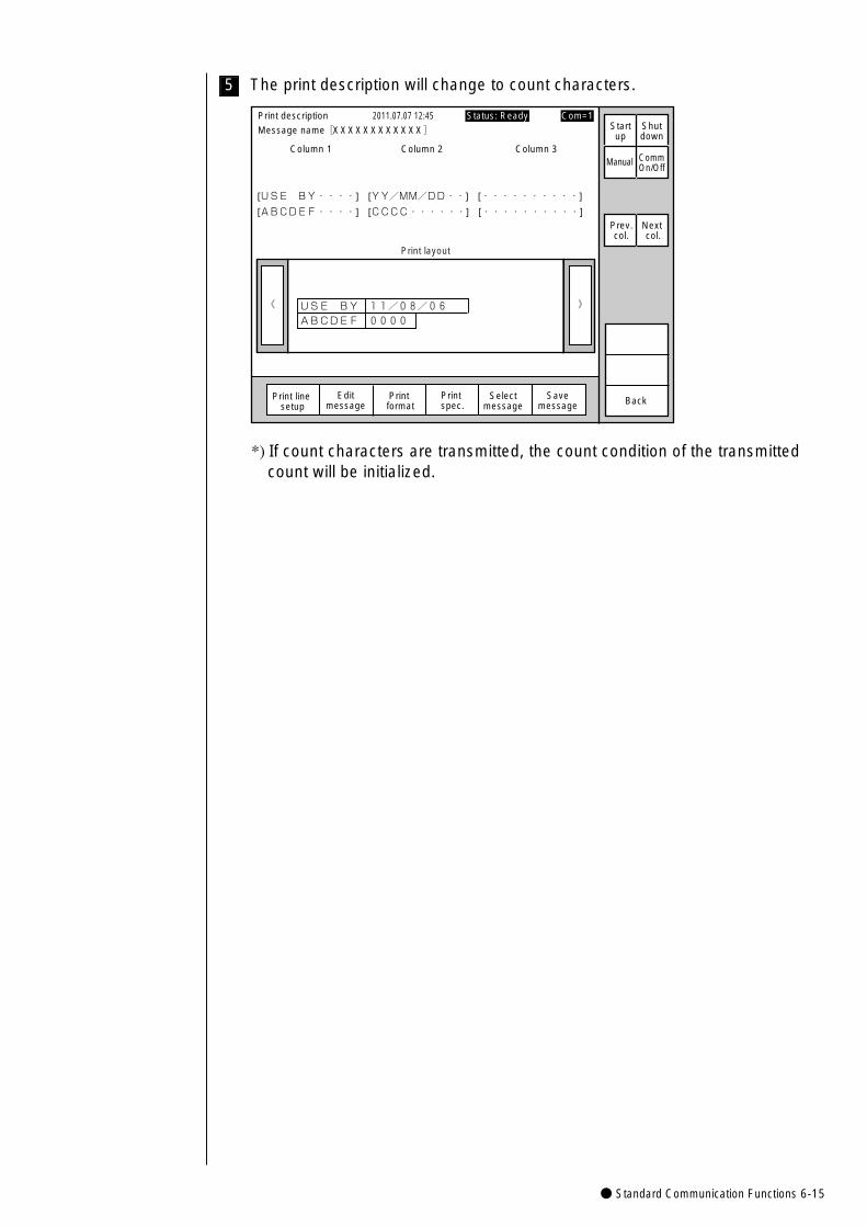
● Standard Communication Functions 6-15
5 The print description will change to count characters.
》《
Column 1 Column 2 Column 3
[USE BY・・・・] [YY/MM/DD・・] [・・・・・・・・・・]
[ABCDEF・・・・] [CCCC・・・・・・] [・・・・・・・・・・]
Print description 2011.07.07 12:45
Selectmessage
Message name[XXXXXXXXXXXX] Startup
Shutdown
Manual
Print line setup
Editmessage
Print format
Print spec.
Print layout
Prev.col.
Next col.
Savemessage Back
USE BY 11/08/06�ABCDEF 0000�
CommOn/Off
Status: Ready Com=1
*) If count characters are transmitted, the count condition of the transmittedcount will be initialized.
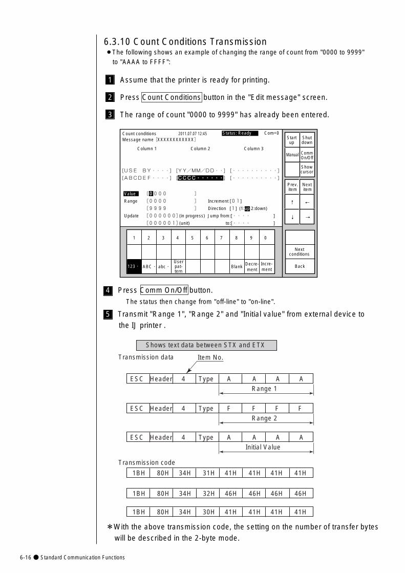
6-16● Standard Communication Functions
Shows text data between STX and ETX
Transmission data Item No.
Transmission code
1BH 80H 34H 31H 41H 41H 41H 41H
ESC Header 4 Type A A A A Range 1
ESC Header 4 Type F F F F Range 2
ESC Header 4 Type A A A A Initial Value
1BH 80H 34H 32H 46H 46H 46H 46H
1BH 80H 34H 30H 41H 41H 41H 41H
4 Press Comm On/Off button.
The status then change from "off-line" to "on-line".
5 Transmit "Range 1", "Range 2" and "Initial value" from external device to
the IJ printer .
*With the above transmission code, the setting on the number of transfer bytes
will be described in the 2-byte mode.
1 2 3 4 5 6 7 8 9 0
Incre-ment
Decre-ment
Count conditions
Column 1 Column 2 Column 3
�
�
[USE BY・・・・] [YY/MM/DD・・] [・・・・・・・・・・] �
[ABCDEF・・・・] [CCCC・・・・・・] [・・・・・・・・・・]
2011.07.07 12:45
Back
Value [0000 ]
Range [0000 ] Increment [01]
[9999 ] Direction [1] (1:up 2:down)
Update [000000](in progress) Jump from:[・・・・ ]
[000001](unit) to:[・・・・ ]
ABC・�abc・� Blank123・�
Manual
Showcursor
Prev.item
Next item
↓
↑
→
←
Status: Ready Com=0 Message name[XXXXXXXXXXXX] Start
upShutdown
CommOn/Off
Userpat-tern
Nextconditions
6.3.10 Count Conditions Transmission¡The following shows an example of changing the range of count from "0000 to 9999"
to "AAAA to FFFF":
1 Assume that the printer is ready for printing.
2 Press Count Conditions button in the "Edit message" screen.
3 The range of count "0000 to 9999" has already been entered.
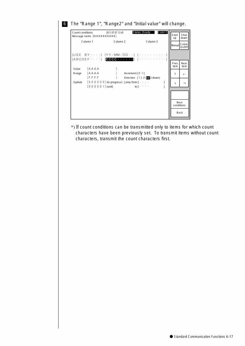
● Standard Communication Functions 6-17
6 The "Range 1", "Range2" and "Initial value" will change.
Count conditions
Column 1 Column 2 Column 3
�
�
[USE BY・・・・] [YY/MM/DD・・] [・・・・・・・・・・] �
[ABCDEF・・・・] [CCCC・・・・・・] [・・・・・・・・・・]
2011.07.07 12:45
Back
Value [AAAA ]
Range [AAAA ] Increment [01]
[FFFF ] Direction [1] (1:up 2:down)
Update [000000](in progress) Jump from:[・・・・ ]
[000001](unit) to:[・・・・ ]
Prev.item
Next item
↓
↑
→
←
Status: Ready Com=1 Message name[XXXXXXXXXXXX]
Manual
Startup
Shutdown
CommOn/Off
Nextconditions
*) If count conditions can be transmitted only to items for which countcharacters have been previously set. To transmit items without countcharacters, transmit the count characters first.
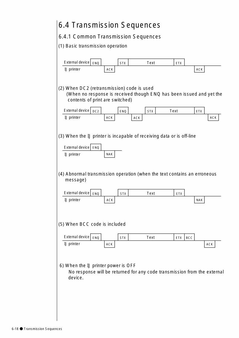
6-18● Transmission Sequences
6.4.1 Common Transmission Sequences
6.4 Transmission Sequences
External device
IJ printer
ENQ
ACK
STX Text ETX
ACK
(1) Basic transmission operation
(2) When DC2 (retransmission) code is used (When no response is received though ENQ has been issued and yet the contents of print are switched)
External device
IJ printer ACK ACKACK
DC2 ENQ STX Text ETX
(3) When the IJ printer is incapable of receiving data or is off-line
External device
IJ printer
ENQ
NAK
(4) Abnormal transmission operation (when the text contains an erroneous message)
No response will be returned for any code transmission from the external device.
(5) When BCC code is included
6) When the IJ printer power is OFF
�
External device
IJ printer
ENQ
ACK
STX Text ETX
NAK
�
External device
IJ printer
ENQ
ACK
STX Text ETX BCC
ACK
�
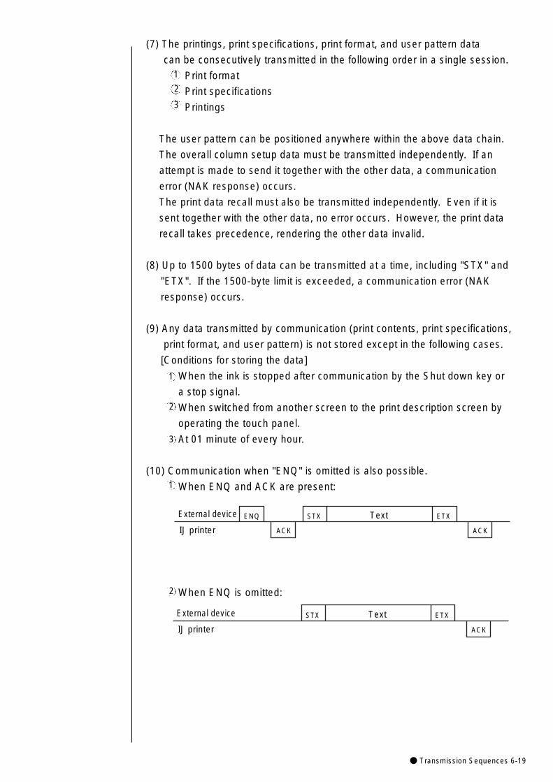
● Transmission Sequences 6-19
(7) The printings, print specifications, print format, and user pattern data
can be consecutively transmitted in the following order in a single session.
Print format
Print specifications
Printings
The user pattern can be positioned anywhere within the above data chain.
The overall column setup data must be transmitted independently. If an
attempt is made to send it together with the other data, a communication
error (NAK response) occurs.
The print data recall must also be transmitted independently. Even if it is
sent together with the other data, no error occurs. However, the print data
recall takes precedence, rendering the other data invalid.
(8) Up to 1500 bytes of data can be transmitted at a time, including "STX" and
"ETX". If the 1500-byte limit is exceeded, a communication error (NAK
response) occurs.
(9) Any data transmitted by communication (print contents, print specifications,
print format, and user pattern) is not stored except in the following cases.
[Conditions for storing the data]
When the ink is stopped after communication by the Shut down key or
a stop signal.
When switched from another screen to the print description screen by
operating the touch panel.
At 01 minute of every hour.
(10) Communication when "ENQ" is omitted is also possible.
When ENQ and ACK are present:
1
2
3
1
2
3
1
External device
IJ printer
ENQ
ACK
STX Text ETX
ACK
When ENQ is omitted:2
External device
IJ printer
STX Text ETX
ACK
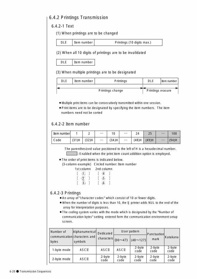
6-20● Transmission Sequences
1-byte mode ASCII ASCII ASCII2-byte 2-byte 2-byte code code code
2-byte mode ASCII2-byte 2-byte 2-byte 2-byte 2-byte code code code code code
DLE Item number Printings DLE Item number
DLE Item number Printings (10 digits max.)
¡The order of print items is indicated below.
6.4.2 Printings Transmission
6.4.2-1 Text
(1) When printings are to be changed
(2) When all 10 digits of printings are to be invalidated
DLE Item number
(3) When multiple printings are to be designated
Printings change Printings erasure
¡Multiple print items can be consecutively transmitted within one session.
¡Print items are to be designated by specifying the item numbers. The item
numbers need not be sorted
6.4.2-2 Item number
Item number 1 2 … 10 … 24 25 … 100
Code (31)H (32)H … (3A)H … (48)H (49)H … (94)H
The parenthesized value positioned to the left of H is a hexadecimal number.
: Enabled when the print item count addition option is employed.
6.4.2-3 Printings¡An array of "character codes" which consist of 10 or fewer digits.¡When the number of digits is less than 10, the IJ printer adds NUL to the end of the
array for interpretation purposes.
¡The coding system varies with the mode which is designated by the "Number of
communication bytes" setting entered form the communication environment setup
screen.
(3-column example) Circled number: Item number1st column 2nd column[ 1 ] [ 4 ][ 2 ] [ 5 ][ 3 ] [ 6 ]
User patternNumber of Alphanumerical Dedicatedcommunication characters and charactersbytes symbols
Katakana(00~47) (48~127)
Punctuation
mark

● Transmission Sequences 6-21
ESC Header 26H Tens position Units position
ESC Header Hundreds position Tens position Units position
Message ASCII codenumber
01 (30)H, (30)H, (31)H
02 (30)H, (30)H, (32)H
…… ……
89 (30)H, (38)H, (39)H
99 (30)H, (39)H, (39)H
High-order byte Low-order byte
(3) Mixture of ASCII and 2-byte codes
(number of communication bytes: 1-byte mode)
(4) Mixture of ASCII and 2-byte codes
(number of communication bytes: 2-byte mode)
6.4.3 Print Data Recall / Transmission
(1) Text For message numbers 001 to 150
* For use only with message numbers 01 to 99, a call can be made
by the following method.
In this case, the data of the hundredth digit is not required.
6.4.2-4 Character codes
(1) 2-byte code (number of communication bytes: 1-byte mode)¡One character
¡Two or more characters
(2) 2-byte code (number of communication bytes: 2-byte mode)
Print data message number
SI High-order byte Low-order byte SO
SI High-order Low-order High-order Low-order High-order Low-order SObyte byte byte byte byte byte
ASCII ASCII SI High-order Low-order High-order Low-order SO ASCIIbyte byte byte byte
ASCII ASCII High-order byte Low-order byte High-order byte Low-order byte ASCII
Message ASCII codenumber
100 (31)H, (30)H, (30)H
101 (31)H, (30)H, (31)H
…… ……
149 (31)H, (34)H, (39)H
150 (31)H, (35)H, (30)H
(2) Print data message number¡An already saved print data number is to be designated as the print data
message number.
¡The message number range is from 01 to 150.
¡The message number is expressed by a combination of three ASCII codes.
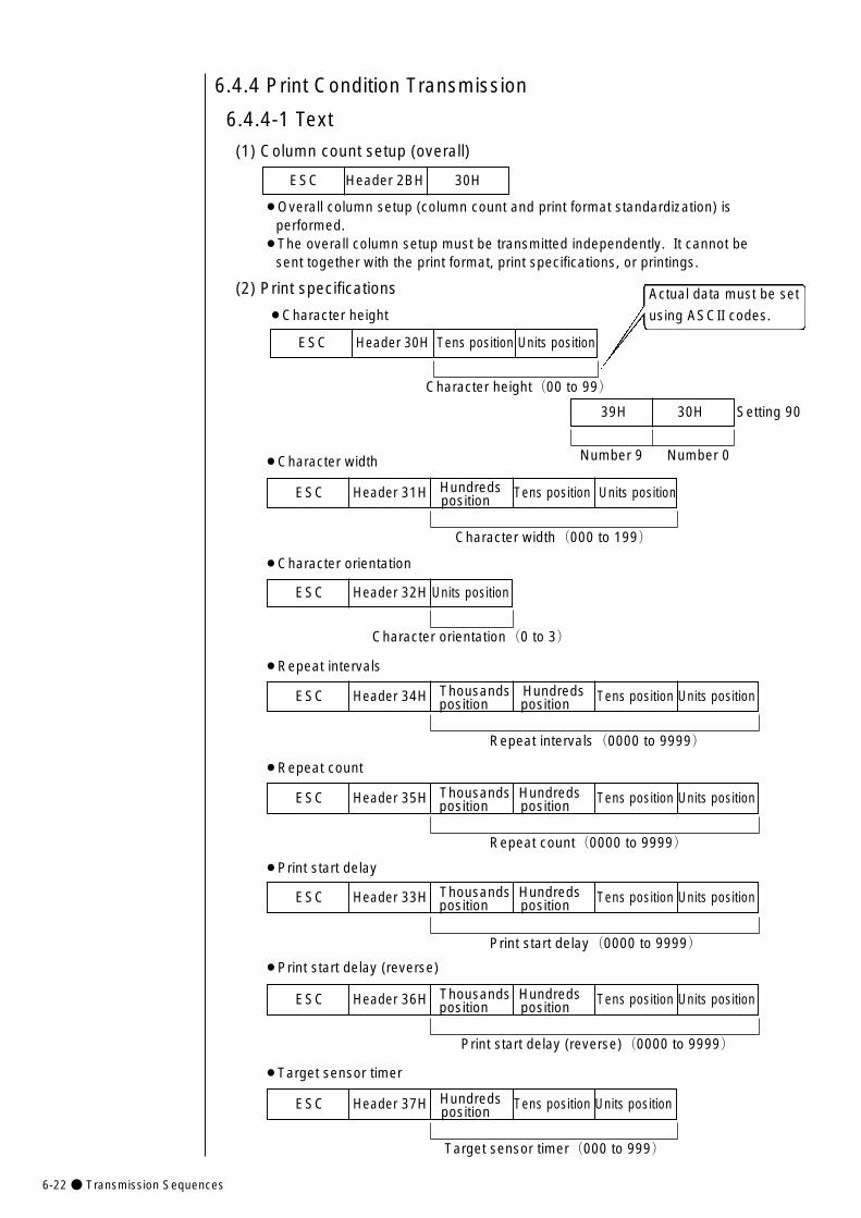
6-22● Transmission Sequences
ESC Header 2BH 30H
6.4.4 Print Condition Transmission
6.4.4-1 Text
(1) Column count setup (overall)
(2) Print specifications
¡Character height
ESC Header 30H Tens position Units position
¡Overall column setup (column count and print format standardization) is performed.
¡The overall column setup must be transmitted independently. It cannot be sent together with the print format, print specifications, or printings.
¡Character width
¡Character orientation
¡Repeat intervals
¡Repeat count
¡Print start delay
¡Print start delay (reverse)
Character height(00 to 99)
Character width(000 to 199)
ESC Header 32H Units position
Character orientation(0 to 3)
ESC Header 34H Thousands Hundreds Tens position Units positionposition position
Repeat intervals(0000 to 9999)
ESC Header 35H Thousands Hundreds Tens position Units positionposition position
Repeat count(0000 to 9999)
ESC Header 33H Thousands Hundreds Tens position Units positionposition position
Print start delay(0000 to 9999)
ESC Header 36H Thousands Hundreds Tens position Units positionposition position
Print start delay (reverse)(0000 to 9999)
39H 30H Setting 90
Number 9 Number 0
Actual data must be set
using ASCII codes.
¡Target sensor timer
ESC Header 37H Hundreds Tens position Units positionposition
Target sensor timer(000 to 999)
ESC Header 31H Hundreds Tens position Units positionposition
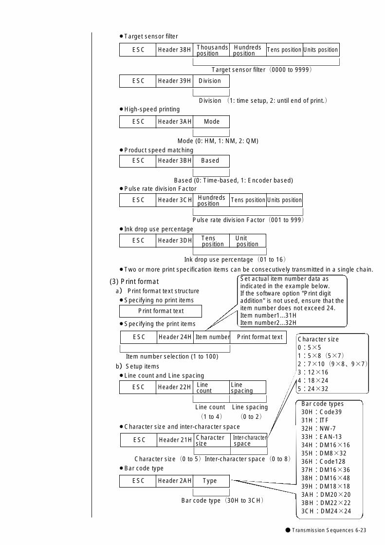
● Transmission Sequences 6-23
(3) Print formata) Print format text structure¡Specifying no print items
Print format text
¡Two or more print specification items can be consecutively transmitted in a single chain.
¡Specifying the print items
¡Character size and inter-character space
¡Bar code type
ESC Header 24H Item number Print format text
Item number selection (1 to 100)
ESC Header 22H Line Linecount spacing
Line count Line spacing
(1 to 4) (0 to 2)
Set actual item number data asindicated in the example below. If the software option "Print digitaddition" is not used, ensure that theitem number does not exceed 24.Item number1...31HItem number2...32H
¡Target sensor filter
ESC Header 38H Thousands Hundreds Tens position Units positionposition position
Target sensor filter(0000 to 9999)
b)Setup items¡Line count and Line spacing
ESC Header 21H Character Inter-charactersize space
Character size(0 to 5)Inter-character space(0 to 8)
ESC Header 2AH Type
Bar code type(30H to 3CH)
Character size0:5×51:5×8(5×7)2:7×10(9×8、9×7)3:12×164:18×245:24×32
Bar code types30H:Code3931H:ITF32H:NW-733H:EAN-1334H:DM16×1635H:DM8×3236H:Code12837H:DM16×3638H:DM16×4839H:DM18×183AH:DM20×203BH:DM22×223CH:DM24×24
ESC Header 39H Division
Division(1: time setup, 2: until end of print.)¡High-speed printing
ESC Header 3AH Mode
Mode (0: HM, 1: NM, 2: QM)
ESC Header 3BH Based
Based (0: Time-based, 1: Encoder based)
¡Product speed matching
¡Pulse rate division Factor
ESC Header 3CH Hundreds Tens position Units positionposition
Pulse rate division Factor(001 to 999)¡Ink drop use percentage
ESC Header 3DH Tens Unitposition position
Ink drop use percentage(01 to 16)
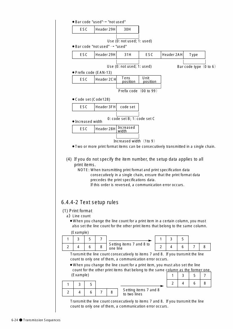
6-24● Transmission Sequences
Transmit the line count consecutively to items 7 and 8. If you transmit the linecount to only one of them, a communication error occurs.
(4) If you do not specify the item number, the setup data applies to all print items.
NOTE: When transmitting print format and print specification data consecutively in a single chain, ensure that the print format data precedes the print specifications data. If this order is reversed, a communication error occurs.
6.4.4-2 Text setup rules
(1) Print formata)Line count¡When you change the line count for a print item in a certain column, you must
also set the line count for the other print items that belong to the same column.
(Example)
Setting items 7 and 8 toone line
1 3 5 7
2 4 6 8
1 3 5
2 4 6 7 8
¡When you change the line count for a print item, you must also set the linecount for the other print items that belong to the same column as the former one. (Example)
Setting items 7 and 8to two lines
1 3 5 7
2 4 6 81 3 5
2 4 6 7 8
Transmit the line count consecutively to items 7 and 8. If you transmit the linecount to only one of them, a communication error occurs.
¡Increased width
¡Two or more print format items can be consecutively transmitted in a single chain.
ESC Header 28H Increasedwidth
Increased width(1to 9)
¡Code set (Code128)
ESC Header 3FH code set
0: code set B; 1: code set C
¡Bar code "used"→ "not used"
ESC Header 29H 30H
Use (0: not used; 1: used)¡Bar code "not used" → "used"
¡Prefix code (EAN-13)
Bar code type(0 to 6)
ESC Header 29H 31H ESC Header 2AH Type
Use (0: not used; 1: used)
ESC Header 2CH Tens Unitposition position
Prefix code(00 to 99)
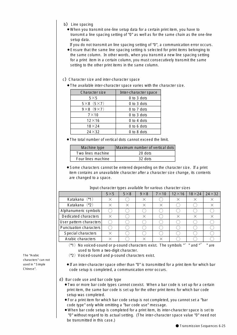
● Transmission Sequences 6-25
Character size5×5
5×8(5×7)9×8(9×7)
7×1012×1618×2424×32
Inter-character space0 to 3 dots0 to 3 dots0 to 7 dots0 to 3 dots0 to 4 dots0 to 6 dots0 to 8 dots
24×32××◯×◯◯◯◯
Maximum number of vertical dots20 dots32 dots
¡The total number of vertical dots cannot exceed the limit.
Machine typeTwo lines machineFour lines machine
¡Some characters cannot be entered depending on the character size. If a print item contains an unavailable character after a character size change, its contents are changed to a space.
Input character types available for various character sizes
Katakana(*1)Katakana(*2)
Alphanumeric symbolsDedicated characters
User pattern charactersPunctuation characters
Special charactersArabic characters
5×5××◯×◯◯××
5×8◯×◯◯◯◯◯◯
9×8××◯×◯◯◯×
7×10◯×◯◯◯◯◯×
12×16×◯◯×◯◯◯◯
18×24×◯◯×◯◯◯◯
(*1)No voiced-sound or p-sound characters exist. The symbols "゛" and "。
" are used to form a two-digit character.
(*2)Voiced-sound and p-sound characters exist.
¡If an inter-character space other than "0" is transmitted for a print item for which barcode setup is completed, a communication error occurs.
d)Bar code use and bar code type¡Two or more bar code types cannot coexist. When a bar code is set up for a certain
print item, the same bar code is set up for the other print items for which bar code setup was completed.
¡For a print item for which bar code setup is not completed, you cannot set a "bar code type" only while omitting a "bar code use" message.
¡When bar code setup is completed for a print item, its inter-character space is set to"0" without regard to its actual setting. (The inter-character space value "0" need not be transmitted in this case.)
c)Character size and inter-character space
¡The available inter-character space varies with the character size.
The "Arabic
characters" can not
used in " Simple
Chinese".
b) Line spacing¡When you transmit one-line setup data for a certain print item, you have to
transmit a line spacing setting of "0" as well as for the same chain as the one-line setup data.If you do not transmit an line spacing setting of "0", a communication error occurs.
¡Ensure that the same line spacing setting is selected for print items belonging to the same column. In other words, when you transmit a new line spacing setting for a print item in a certain column, you must consecutively transmit the same setting to the other print items in the same column.
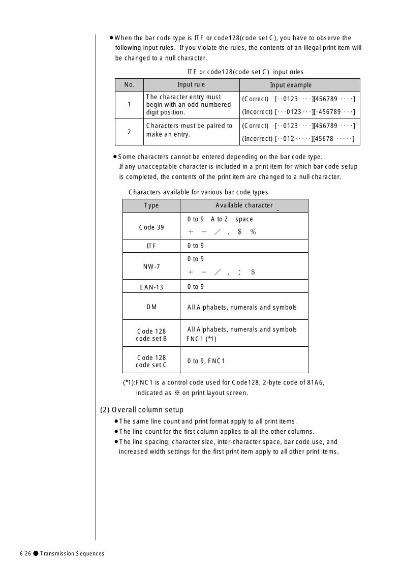
6-26● Transmission Sequences
¡Some characters cannot be entered depending on the bar code type.
If any unacceptable character is included in a print item for which bar code setup
is completed, the contents of the print item are changed to a null character.
Characters available for various bar code types
(2) Overall column setup
¡The same line count and print format apply to all print items.
¡The line count for the first column applies to all the other columns.
¡The line spacing, character size, inter-character space, bar code use, and
increased width settings for the first print item apply to all other print items.
(*1):FNC1 is a control code used for Code128, 2-byte code of 81A6,
indicated as ※ on print layout screen.
¡When the bar code type is ITF or code128(code set C), you have to observe the
following input rules. If you violate the rules, the contents of an illegal print item will
be changed to a null character.
ITF or code128(code set C) input rules
Input example
(Correct) [・・0123・・・・][456789 ・・・・]
(Incorrect) [・・・0123・・・][・456789 ・・・]
(Correct) [・・0123・・・・][456789 ・・・・]
(Incorrect) [・・012・・・・・][45678 ・・・・・]
No.
1
2
Input rule
The character entry must begin with an odd-numbered digit position.
Characters must be paired to make an entry.
Type
Code 39
ITF
NW-7
EAN-13
DM
Code 128code set B
Code 128code set C
Available character
0 to 9 A to Z space
+ - / . $ %
0 to 9
0 to 9
+ - / . : $
0 to 9
All Alphabets, numerals and symbols
All Alphabets, numerals and symbolsFNC1 (*1)
0 to 9, FNC1
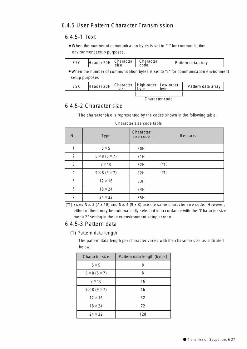
● Transmission Sequences 6-27
No.
1
2
3
4
5
6
7
ESC Header 20H Character Character Pattern data arraysize code
6.4.5 User Pattern Character Transmission
6.4.5-1 Text¡When the number of communication bytes is set to "1" for communication
environment setup purposes.
Character code
¡When the number of communication bytes is set to "2" for communication environment
setup purposes
ESC Header 20H Character High-order Low-order Pattern data arraysize byte byte
6.4.5-2 Character size
The character size is represented by the codes shown in the following table.
Character size code table
Type
5×5
5×8 (5×7)
7×10
9×8 (9×7)
12×16
18×24
24×32
Charactersize code
30H
31H
32H
32H
33H
34H
35H
Remarks
(*1)
(*1)
(*1) Sizes No. 3 (7 x 10) and No. 4 (9 x 8) use the same character size code. However,
either of them may be automatically selected in accordance with the "Character size
menu 2" setting in the user environment setup screen.
6.4.5-3 Pattern data
(1) Pattern data length
The pattern data length per character varies with the character size as indicated
below.
Character size
5×5
5×8 (5×7)
7×10
9×8 (9×7)
12×16
18×24
24×32
Pattern data length (bytes)
8
8
16
16
32
72
128
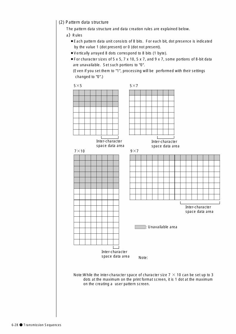
6-28● Transmission Sequences
(2) Pattern data structure
The pattern data structure and data creation rules are explained below.
a)Rules
¡Each pattern data unit consists of 8 bits. For each bit, dot presence is indicated
by the value 1 (dot present) or 0 (dot not present).
¡Vertically arrayed 8 dots correspond to 8 bits (1 byte).
¡For character sizes of 5 x 5, 7 x 10, 5 x 7, and 9 x 7, some portions of 8-bit data
are unavailable. Set such portions to "0".
(Even if you set them to "1", processing will be performed with their settings
changed to "0".)
5×5
7×10
5×7
9×7
: Unavailable area
Inter-characterspace data area
Inter-characterspace data area
Inter-characterspace data area
Inter-characterspace data area Note:
Note:While the inter-character space of character size 7 × 10 can be set up to 3dots at the maximum on the print format screen, it is 1 dot at the maximum on the creating a user pattern screen.
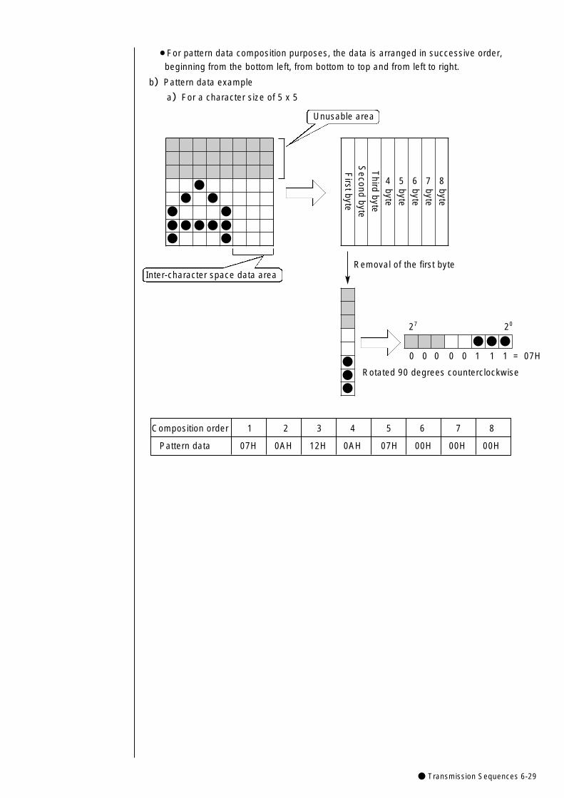
● Transmission Sequences 6-29
¡For pattern data composition purposes, the data is arranged in successive order,
beginning from the bottom left, from bottom to top and from left to right.
b)Pattern data example
a)For a character size of 5 x 5
Rotated 90 degrees counterclockwise
Inter-character space data area
●● ●
● ●●●●●●● ●
Firstbyte
Second
byteT
hirdbyte
4byte5byte
6byte
7byte
8byte
●●●
●●●
Unusable area
Removal of the first byte
0 0 0 0 0 1 1 1 = 07H
27 20
Composition order 1 2 3 4 5 6 7 8
Pattern data 07H 0AH 12H 0AH 07H 00H 00H 00H
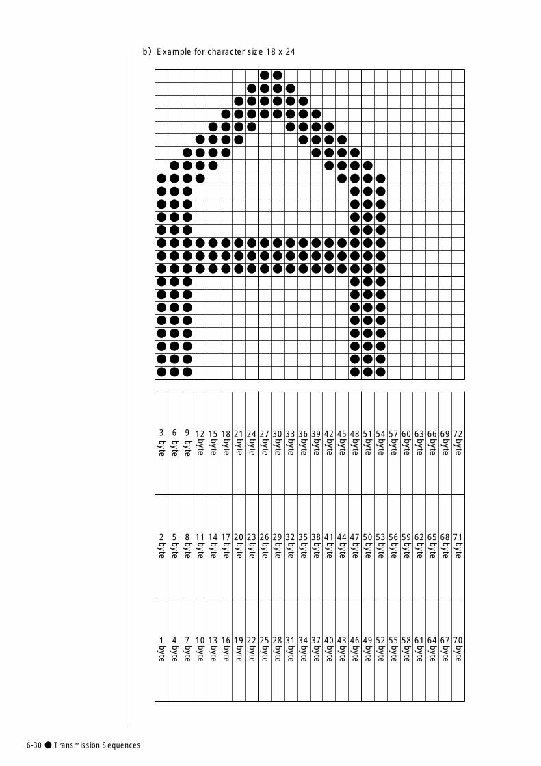
6-30● Transmission Sequences
b)Example for character size 18 x 24
●●●
●●●●●●●
●●●●●●●●
●●●●
●●●●●●●●●●●●●●
●●●●●●●●●●●●●●●●
●●●● ●●●●●●● ●●●●●● ●●●●●● ●●●●●● ●●●●●●●●●●●●●●●●●●●●●●●●●●●●●●●●●●●●●●●●●●●●●●●●●●●●●●●●●●●● ●●●●●● ●●●●●● ●●●●●● ●●●●●● ●●●●●● ●●●●●● ●●●●●● ●●●
3byte
6byte
9byte
12byte
15byte
18byte
21byte
24byte
2byte
5byte
8byte
11byte
14byte
17byte
20byte
23byte
1byte
4byte
7byte
10byte
13byte
16byte
19byte
22byte
27byte
30byte
33byte
36byte
39byte
42byte
45byte
48byte
51byte
54byte
57byte
60byte
63byte
66byte
69byte
72byte
26byte
29byte
32byte
35byte
38byte
41byte
44byte
47byte
50byte
53byte
56byte
59byte
62byte
65byte
68byte
71byte
25byte
28byte
31byte
34byte
37byte
40byte
43byte
46byte
49byte
52byte
55byte
58byte
61byte
64byte
67byte
70byte
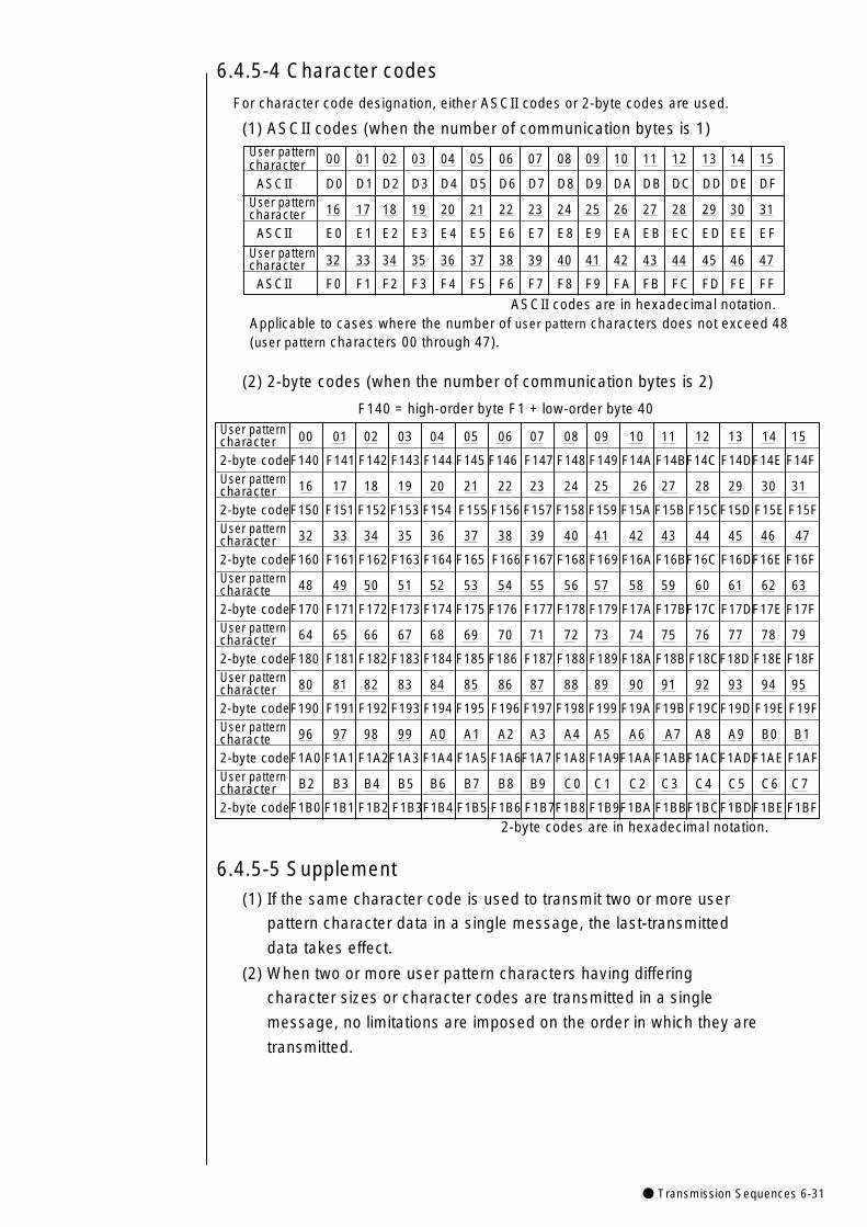
● Transmission Sequences 6-31
6.4.5-4 Character codes
For character code designation, either ASCII codes or 2-byte codes are used.
(1) ASCII codes (when the number of communication bytes is 1)
Applicable to cases where the number of user pattern characters does not exceed 48(user pattern characters 00 through 47).
(2) 2-byte codes (when the number of communication bytes is 2)
F140 = high-order byte F1 + low-order byte 40
User pattern 00 01 02 03 04 05 06 07 08 09 10 11 12 13 14 15characterASCII D0 D1 D2 D3 D4 D5 D6 D7 D8 D9 DA DB DC DD DE DF
User pattern 16 17 18 19 20 21 22 23 24 25 26 27 28 29 30 31characterASCII E0 E1 E2 E3 E4 E5 E6 E7 E8 E9 EA EB EC ED EE EF
User pattern 32 33 34 35 36 37 38 39 40 41 42 43 44 45 46 47characterASCII F0 F1 F2 F3 F4 F5 F6 F7 F8 F9 FA FB FC FD FE FF
User pattern 00 01 02 03 04 05 06 07 08 09 10 11 12 13 14 15character2-byte codeF140 F141 F142 F143 F144 F145 F146 F147 F148 F149 F14A F14BF14C F14DF14E F14FUser pattern 16 17 18 19 20 21 22 23 24 25 26 27 28 29 30 31character2-byte codeF150 F151 F152 F153 F154 F155 F156 F157 F158 F159 F15A F15B F15CF15D F15E F15FUser pattern 32 33 34 35 36 37 38 39 40 41 42 43 44 45 46 47character2-byte codeF160 F161 F162 F163 F164 F165 F166 F167 F168 F169 F16A F16BF16C F16DF16E F16FUser pattern 48 49 50 51 52 53 54 55 56 57 58 59 60 61 62 63characte2-byte codeF170 F171 F172 F173 F174 F175 F176 F177 F178 F179 F17A F17BF17C F17DF17E F17FUser pattern 64 65 66 67 68 69 70 71 72 73 74 75 76 77 78 79character2-byte codeF180 F181 F182 F183 F184 F185 F186 F187 F188 F189 F18A F18B F18CF18D F18E F18FUser pattern 80 81 82 83 84 85 86 87 88 89 90 91 92 93 94 95character2-byte codeF190 F191 F192 F193 F194 F195 F196 F197 F198 F199 F19A F19B F19CF19D F19E F19FUser pattern 96 97 98 99 A0 A1 A2 A3 A4 A5 A6 A7 A8 A9 B0 B1characte2-byte codeF1A0 F1A1 F1A2F1A3 F1A4 F1A5 F1A6F1A7 F1A8 F1A9F1AA F1ABF1ACF1ADF1AE F1AFUser pattern B2 B3 B4 B5 B6 B7 B8 B9 C0 C1 C2 C3 C4 C5 C6 C7character 2-byte codeF1B0 F1B1 F1B2 F1B3F1B4 F1B5 F1B6 F1B7F1B8 F1B9F1BA F1BBF1BCF1BDF1BEF1BF
ASCII codes are in hexadecimal notation.
6.4.5-5 Supplement(1) If the same character code is used to transmit two or more user
pattern character data in a single message, the last-transmitted
data takes effect.
(2) When two or more user pattern characters having differing
character sizes or character codes are transmitted in a single
message, no limitations are imposed on the order in which they are
transmitted.
2-byte codes are in hexadecimal notation.
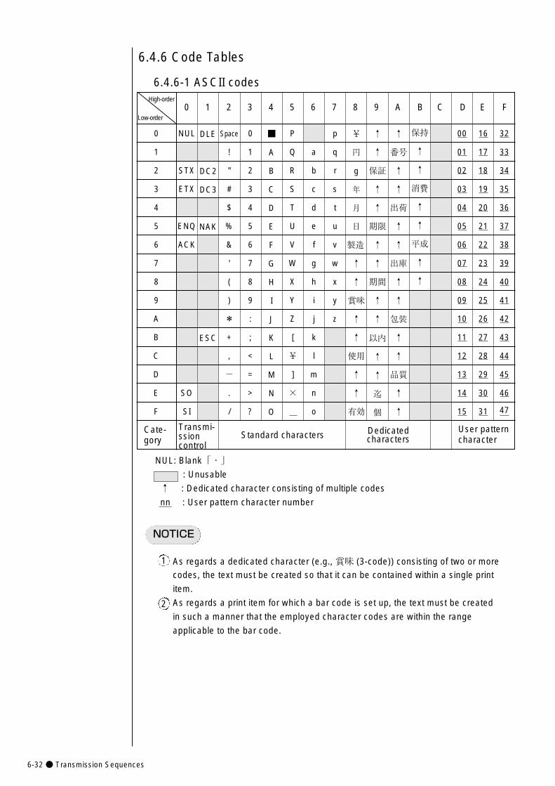
6-32● Transmission Sequences
NUL
STX
ETX
ENQ
ACK
SO
SI
16
17
18
19
20
21
22
23
24
25
26
27
28
29
30
31
00
01
02
03
04
05
06
07
08
09
10
11
12
13
14
15
User pattern character
保持
↑
↑
消費
↑
↑
平成
↑
↑
p
q
r
s
t
u
v
w
x
y
z
32
33
34
35
36
37
38
39
40
41
42
43
44
45
46
47
Space
!
"
#
$
%
&
'
(
)
*
+
,
-
.
/
0
1
2
3
4
5
6
7
8
9
A
B
C
D
E
F
0 1 2 3 4 5 6 7 8 9 A B C D E F
DLE
DC2
DC3
NAK
ESC
P
Q
R
S
T
U
V
W
X
Y
Z
[
¥
]
×
NUL: Blank「・」: Unusable
↑ : Dedicated character consisting of multiple codes
nn : User pattern character number
6.4.6 Code Tables
6.4.6-1 ASCII codes
Low-order
High-order
NOTICE
As regards a dedicated character (e.g., 賞味 (3-code)) consisting of two or more
codes, the text must be created so that it can be contained within a single print
item.
As regards a print item for which a bar code is set up, the text must be created
in such a manner that the employed character codes are within the range
applicable to the bar code.
1
2
Standard characters
↑
番号
↑
↑
出荷
↑
↑
出庫
↑
↑
包装
↑
↑
品質
↑
↑
↑
↑
保証
↑
↑
期限
↑
↑
期間
↑
↑
以内
↑
↑
迄
個
¥
円
g
年
月
日
製造
↑
↑
賞味
↑
↑
使用
↑
↑
有効
a
b
c
d
e
f
g
h
i
j
k
l
m
n
o
■
A
B
C
D
E
F
G
H
I
J
K
L
M
N
O
0
1
2
3
4
5
6
7
8
9
:
;
<
=
>
?
Cate-gory
Transmi- ssion control
Dedicated characters
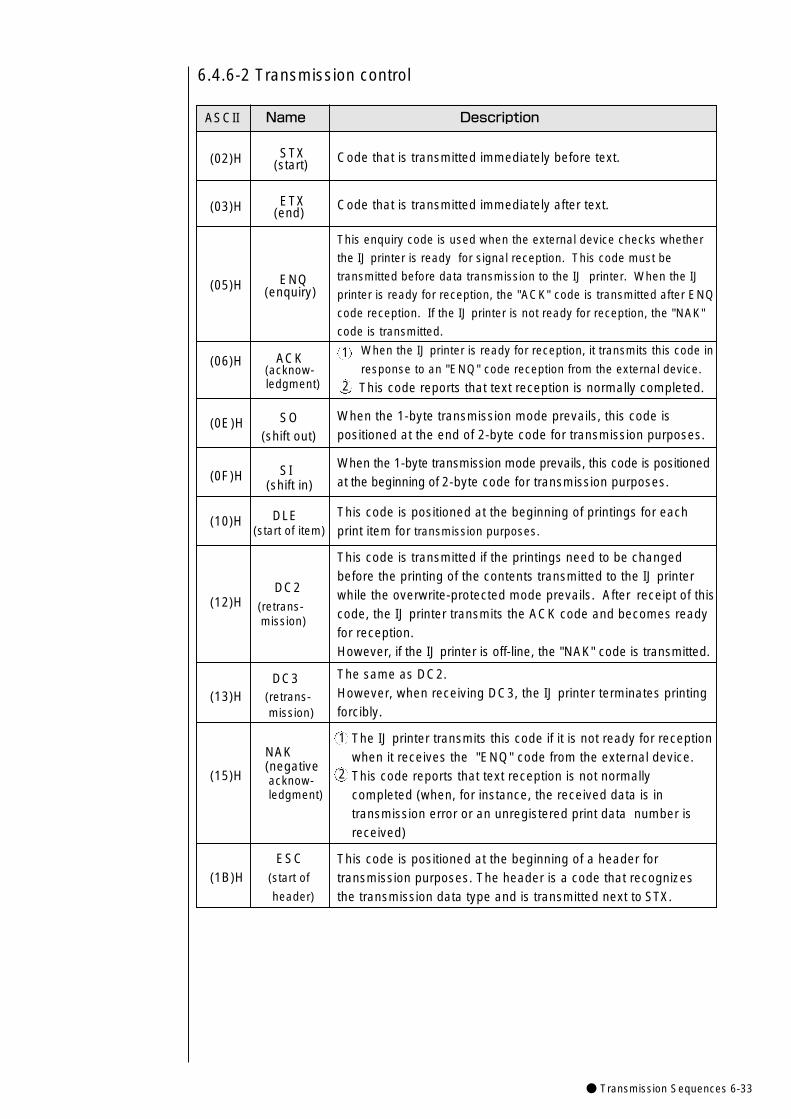
● Transmission Sequences 6-33
Code that is transmitted immediately before text.
Code that is transmitted immediately after text.
This enquiry code is used when the external device checks whether
the IJ printer is ready for signal reception. This code must be
transmitted before data transmission to the IJ printer. When the IJ
printer is ready for reception, the "ACK" code is transmitted after ENQ
code reception. If the IJ printer is not ready for reception, the "NAK"
code is transmitted.
When the IJ printer is ready for reception, it transmits this code in
response to an "ENQ" code reception from the external device.
This code reports that text reception is normally completed.
When the 1-byte transmission mode prevails, this code ispositioned at the end of 2-byte code for transmission purposes.
When the 1-byte transmission mode prevails, this code is positioned at the beginning of 2-byte code for transmission purposes.
This code is positioned at the beginning of printings for each print item for transmission purposes.
This code is transmitted if the printings need to be changedbefore the printing of the contents transmitted to the IJ printerwhile the overwrite-protected mode prevails. After receipt of thiscode, the IJ printer transmits the ACK code and becomes readyfor reception. However, if the IJ printer is off-line, the "NAK" code is transmitted.
The same as DC2.However, when receiving DC3, the IJ printer terminates printingforcibly.
The IJ printer transmits this code if it is not ready for receptionwhen it receives the "ENQ" code from the external device.This code reports that text reception is not normally completed (when, for instance, the received data is in transmission error or an unregistered print data number isreceived)
This code is positioned at the beginning of a header for transmission purposes. The header is a code that recognizesthe transmission data type and is transmitted next to STX.
(02)H STX(start)
(03)H ETX(end)
(05)H ENQ (enquiry)
ACK(06)H (acknow- ledgment)
(0E)H SO(shift out)
(0F)H SI(shift in)
(10)H DLE(start of item)
DC2(12)H (retrans-
mission)
DC3(13)H (retrans-
mission)
NAK(negative
(15)H acknow- ledgment)
ESC (1B)H (start of
header)
ASCII Name Description
6.4.6-2 Transmission control
1
2
1
2
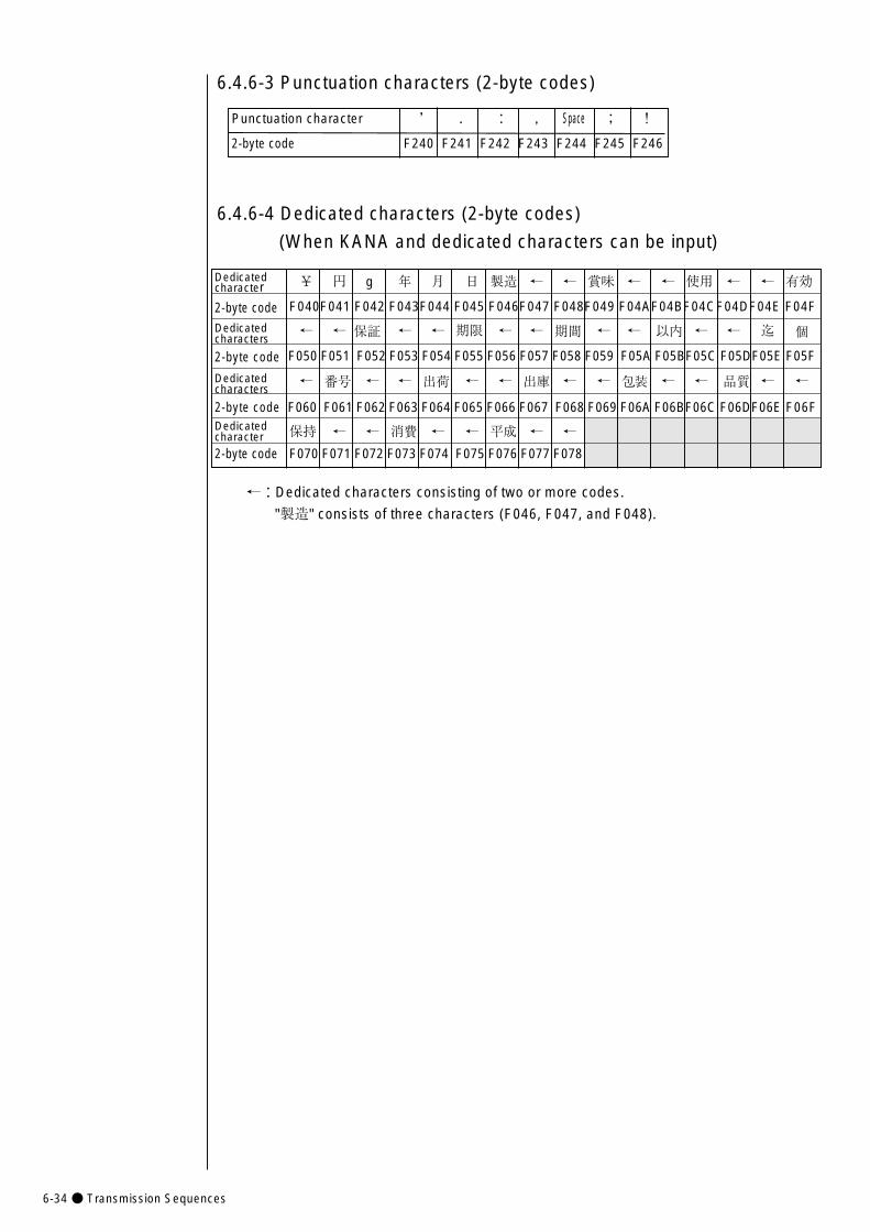
6-34● Transmission Sequences
Dedicated ¥ 円 g 年 月 日 製造 ← ← 賞味 ← ← 使用 ← ← 有効character
2-byte code F040F041 F042 F043F044 F045 F046F047 F048F049 F04AF04BF04CF04DF04E F04F
Dedicated ← ← 保証 ← ← 期限 ← ← 期間 ← ← 以内 ← ← 迄 個characters
2-byte code F050 F051 F052 F053 F054 F055 F056 F057 F058 F059 F05A F05BF05C F05DF05E F05F
Dedicated ← 番号 ← ← 出荷 ← ← 出庫 ← ← 包装 ← ← 品質 ← ←characters
2-byte code F060 F061 F062 F063 F064 F065 F066 F067 F068 F069 F06A F06BF06C F06DF06E F06FDedicated 保持 ← ← 消費 ← ← 平成 ← ←character
2-byte code F070 F071 F072 F073 F074 F075 F076 F077 F078
Punctuation character ’ . : , Space ; !
2-byte code F240 F241 F242 F243 F244 F245 F246
6.4.6-3 Punctuation characters (2-byte codes)
6.4.6-4 Dedicated characters (2-byte codes)
(When KANA and dedicated characters can be input)
←:Dedicated characters consisting of two or more codes.
"製造" consists of three characters (F046, F047, and F048).
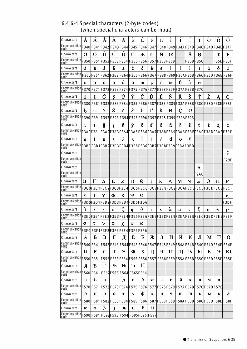
● Transmission Sequences 6-35
6.4.6-4 Special characters (2-byte codes) (when special characters can be input)
Characters
Communication F340 F341F342 F343F344F345 F346F347 F348F349 F34AF34BF34CF34DF34EF34Fcode Characters
Communication F350 F351 F352 F353F354 F355 F356F357 F358F359 F35BF35C F35E F35Fcode Characters
Communication F360F361 F362 F363 F364 F365 F366 F367 F388F369 F36AF36BF36CF36DF36E F36Fcode Characters
Communication F370 F371 F372 F373F374 F375 F376F377 F378F379 F37AF37BF37Ccode Characters
Communication F380 F381 F382 F383F384 F385 F386F387 F388 F389F38AF38BF38CF38DF38E F38Fcode Characters
Communication F390 F391 F392 F393 F394 F395 F396 F397 F398 F399 F39AF39Bcode Characters
Communication F3A0F3A1F3A2F3A3F3A4F3A5F3A6F3A7F3A8F3A9F3AAF3ABF3ACF3ADF3AEF3AFcode Characters
Communication F3B0 F3B1F3B2F3B3F3B4F3B5F3B6F3B7F3B8F3B9F3BAF3BBcode Characters
Communication F29Fcode Characters
Communication F2ACcode Characters
Communication F3C0F3C1F3C2F3C3F3C4F3C5F3C6F3C7F3C8F3C9F3CAF3CBF3CCF3CDF3CEF3CFcode Characters
Communication F3D0F3D1F3D2F3D3F3D4F3D5F3D6 F3DFcode Characters
Communication F3E0F3E1F3E2F3E3F3E4F3E5F3E6F3E7F3E8F3E9F3EAF3EBF3ECF3EDF3EEF3EFcode Characters
Communication F3F0 F3F1F3F2F3F3F3F4 F3F5F3F6code Characters
Communication F540 F541 F542 F543 F544 F545 F546F547 F548F549 F54AF54BF54CF54DF54E F54Fcode Characters
Communication F550 F551 F552 F553F554 F555 F556F557 F558F559 F55AF55BF55CF55DF55E F55Fcode Characters
Communication F560 F561 F562F563 F564 F565F566code Characters
Communication F570 F571 F572 F573F574 F575 F576F577 F578F579 F57AF57BF57CF57DF57Ecode Characters
Communication F580 F581 F582 F583F584 F585 F586F587 F588F589 F58AF58BF58CF58DF58E F58Fcode Characters
Communication F590 F591 F592F593 F594 F595F596 F597code
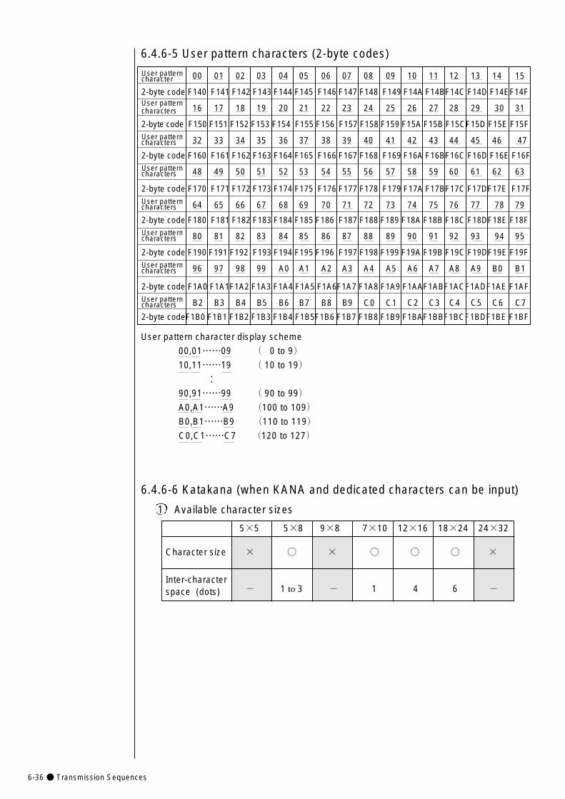
6-36● Transmission Sequences
User pattern 00 01 02 03 04 05 06 07 08 09 10 11 12 13 14 15character
2-byte code F140 F141 F142 F143 F144 F145 F146 F147 F148 F149 F14A F14BF14C F14D F14EF14FUser pattern
16 17 18 19 20 21 22 23 24 25 26 27 28 29 30 31characters
2-byte code F150 F151 F152 F153 F154 F155 F156 F157 F158 F159 F15A F15B F15CF15D F15E F15FUser pattern 32 33 34 35 36 37 38 39 40 41 42 43 44 45 46 47characters
2-byte code F160 F161 F162 F163 F164 F165 F166 F167 F168 F169 F16A F16BF16C F16D F16E F16FUser pattern 48 49 50 51 52 53 54 55 56 57 58 59 60 61 62 63characters
2-byte code F170 F171 F172 F173 F174 F175 F176 F177 F178 F179 F17A F17BF17C F17DF17E F17FUser pattern 64 65 66 67 68 69 70 71 72 73 74 75 76 77 78 79characters
2-byte code F180 F181 F182 F183 F184 F185 F186 F187 F188 F189 F18A F18B F18C F18DF18E F18FUser pattern 80 81 82 83 84 85 86 87 88 89 90 91 92 93 94 95characters
2-byte code F190 F191 F192 F193 F194 F195 F196 F197 F198 F199 F19A F19B F19C F19DF19E F19FUser pattern 96 97 98 99 A0 A1 A2 A3 A4 A5 A6 A7 A8 A9 B0 B1characters
2-byte code F1A0 F1A1F1A2 F1A3 F1A4 F1A5 F1A6F1A7 F1A8 F1A9 F1AAF1ABF1ACF1ADF1AE F1AF User pattern B2 B3 B4 B5 B6 B7 B8 B9 C0 C1 C2 C3 C4 C5 C6 C7characters
2-byte codeF1B0 F1B1 F1B2 F1B3 F1B4 F1B5F1B6 F1B7 F1B8 F1B9 F1BAF1BBF1BCF1BDF1BE F1BF
6.4.6-5 User pattern characters (2-byte codes)
User pattern character display scheme
00,01……09 ( 0 to 9)10,11……19 ( 10 to 19)
:90,91……99 ( 90 to 99)A0,A1……A9 (100 to 109)B0,B1……B9 (110 to 119)C0,C1……C7 (120 to 127)
6.4.6-6 Katakana (when KANA and dedicated characters can be input)
5×5 5×8 9×8 7×10 12×16 18×24 24×32
Character size × ○ × ○ ○ ○ ×
Inter-character space (dots) - 1 to 3 - 1 4 6 -
1 Available character sizes
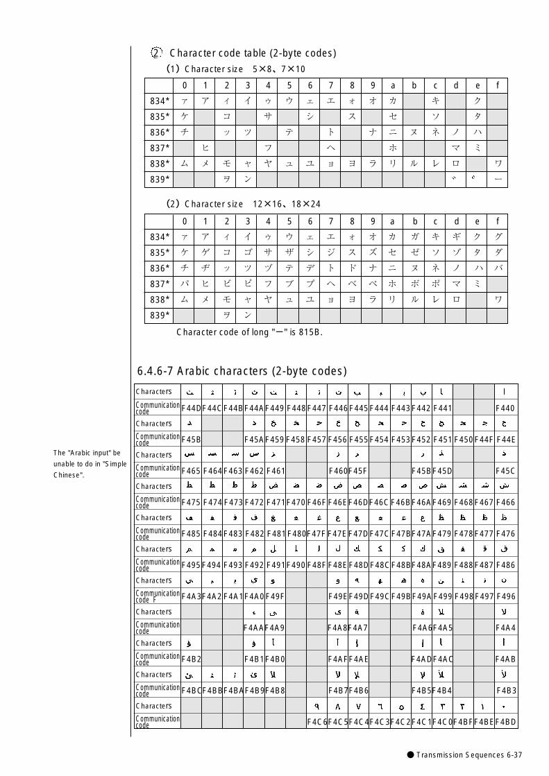
● Transmission Sequences 6-37
2 Character code table (2-byte codes)
(1)Character size 5×8、7×10
(2)Character size 12×16、18×24
0 1 2 3 4 5 6 7 8 9 a b c d e f
834* ァ ア ィ イ ゥ ウ ェ エ ォ オ カ キ ク
835* ケ コ サ シ ス セ ソ タ
836* チ ッ ツ テ ト ナ ニ ヌ ネ ノ ハ
837* ヒ フ ヘ ホ マ ミ
838* ム メ モ ャ ヤ ュ ユ ョ ヨ ラ リ ル レ ロ ワ
839* ヲ ン ー
0 1 2 3 4 5 6 7 8 9 a b c d e f
834* ァ ア ィ イ ゥ ウ ェ エ ォ オ カ ガ キ ギ ク グ
835* ケ ゲ コ ゴ サ ザ シ ジ ス ズ セ ゼ ソ ゾ タ ダ
836* チ ヂ ッ ツ ヅ テ デ ト ド ナ ニ ヌ ネ ノ ハ バ
837* パ ヒ ビ ピ フ ブ プ ヘ ベ ペ ホ ボ ポ マ ミ
838* ム メ モ ャ ヤ ュ ユ ョ ヨ ラ リ ル レ ロ ワ
839* ヲ ン
Characters
Communication F44DF44CF44BF44AF449 F448F447 F446F445F444 F443F442 F441 F440code Characters
Communication F45B F45AF459 F458 F457 F456 F455F454 F453F452 F451 F450F44F F44Ecode Characters
Communication F465 F464F463 F462 F461 F460F45F F45BF45D F45Ccode Characters
Communication F475 F474 F473 F472 F471F470 F46FF46EF46DF46CF46BF46AF469 F468F467 F466code Characters
Communication F485 F484F483 F482 F481F480F47FF47EF47DF47CF47BF47AF479 F478F477 F476code Characters
Communication F495F494 F493 F492 F491F490 F48FF48EF48DF48CF48BF48AF489 F488F487 F486 code Characters
Communication F4A3F4A2 F4A1F4A0F49F F49EF49DF49CF49BF49AF499 F498F497 F496code FCharacters
Communication F4AAF4A9 F4A8F4A7 F4A6F4A5 F4A4code Characters
Communication F4B2 F4B1F4B0 F4AFF4AE F4ADF4AC F4ABcode Characters
Communication F4BCF4BBF4BAF4B9F4B8 F4B7F4B6 F4B5F4B4 F4B3codeCharacters
Communication F4C6F4C5F4C4F4C3F4C2F4C1F4C0F4BFF4BEF4BD code
6.4.6-7 Arabic characters (2-byte codes)
Character code of long "-" is 815B.
The "Arabic input" be
unable to do in "Simple
Chinese".
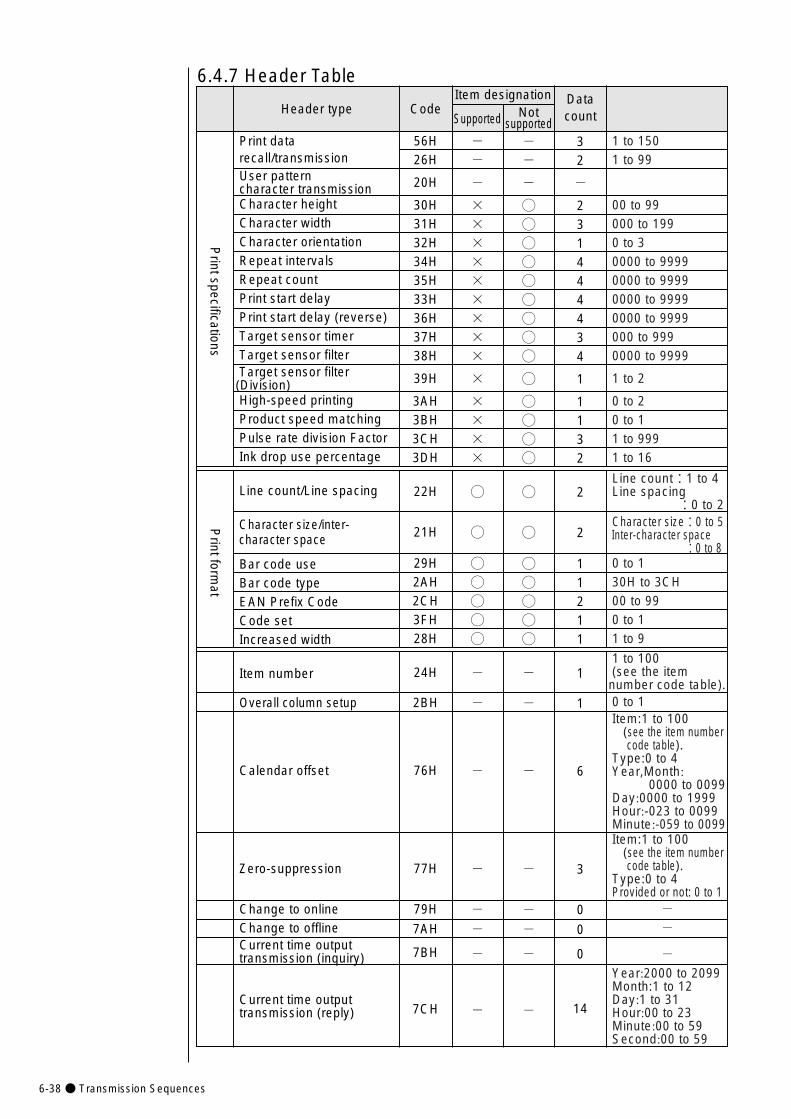
Data section(Do not use ASCIIcodes.)1 to 1501 to 99
00 to 99000 to 1990 to 30000 to 99990000 to 99990000 to 99990000 to 9999000 to 9990000 to 9999
1 to 2
0 to 20 to 11 to 9991 to 16
Line count:1 to 4Line spacing
:0 to 2Character size:0 to 5Inter-character space
:0 to 80 to 130H to 3CH00 to 990 to 11 to 9
1 to 100(see the itemnumber code table).0 to 1Item:1 to 100
(see the item numbercode table).
Type:0 to 4Year,Month:
0000 to 0099Day:0000 to 1999Hour:-023 to 0099Minute:-059 to 0099Item:1 to 100
(see the item numbercode table).
Type:0 to 4Provided or not: 0 to 1
--
-Year:2000 to 2099Month:1 to 12Day:1 to 31Hour:00 to 23Minute:00 to 59Second:00 to 59
6-38● Transmission Sequences
Notsupported--
-
◯◯◯◯◯◯◯◯◯
◯
◯◯◯◯
◯
◯
◯◯◯◯◯
-
-
-
-
--
-
-
Header type
Print data recall/transmissionUser pattern character transmissionCharacter heightCharacter widthCharacter orientationRepeat intervalsRepeat countPrint start delayPrint start delay (reverse)Target sensor timerTarget sensor filterTarget sensor filter (Division)High-speed printingProduct speed matchingPulse rate division FactorInk drop use percentage
Line count/Line spacing
Character size/inter-character space
Bar code useBar code typeEAN Prefix CodeCode setIncreased width
Item number
Overall column setup
Calendar offset
Zero-suppression
Change to onlineChange to offlineCurrent time output transmission (inquiry)
Current time output transmission (reply)
Code
56H26H
20H
30H31H32H34H35H33H36H37H38H
39H
3AH3BH3CH3DH
22H
21H
29H2AH2CH3FH28H
24H
2BH
76H
77H
79H
7AH
7BH
7CH
Supported
--
-
×××××××××
×
××××
◯
◯
◯◯◯◯◯
-
-
-
-
--
-
-
Datacount
32
-
231444434
1
1132
2
2
11211
1
1
6
3
0
0
0
14
Printspecifications
Printform
at
6.4.7 Header TableItem designation
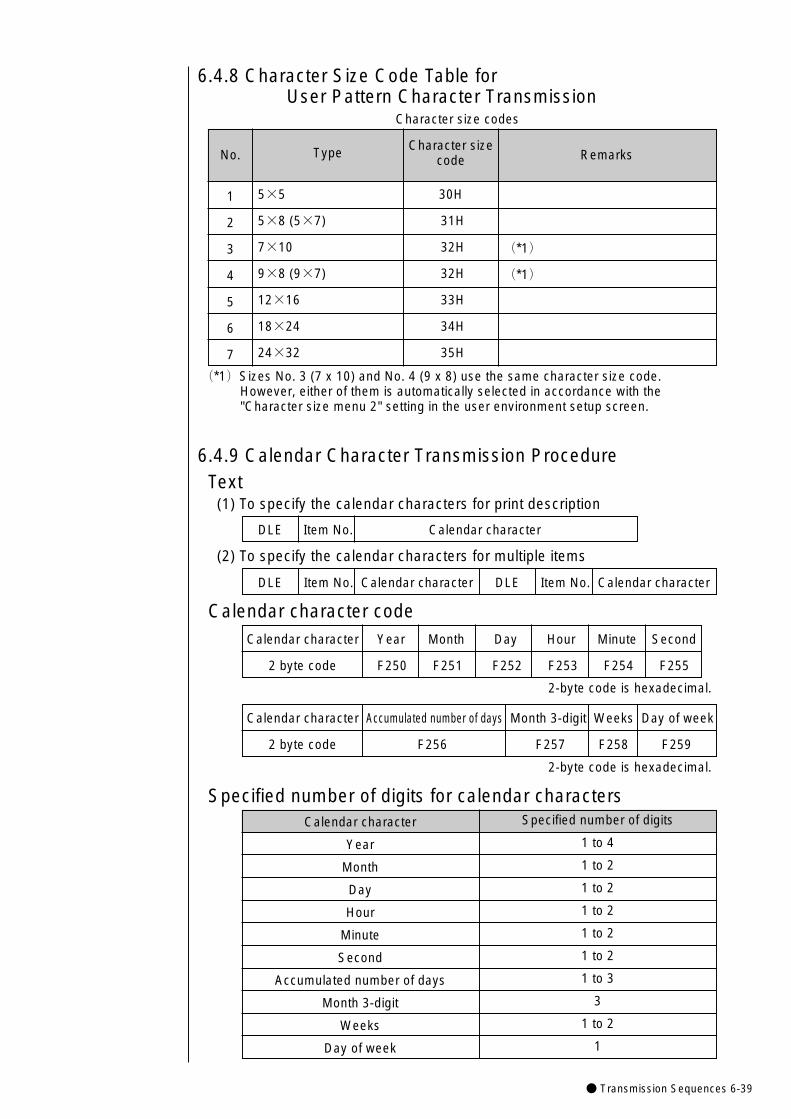
● Transmission Sequences 6-39
Remarks
(*1)
(*1)
Character sizecode
30H
31H
32H
32H
33H
34H
35H
Type
5×5
5×8 (5×7)
7×10
9×8 (9×7)
12×16
18×24
24×32
No.
1
2
3
4
5
6
7
(*1)Sizes No. 3 (7 x 10) and No. 4 (9 x 8) use the same character size code. However, either of them is automatically selected in accordance with the "Character size menu 2" setting in the user environment setup screen.
6.4.8 Character Size Code Table forUser Pattern Character Transmission
Character size codes
Specified number of digits
1 to 4
1 to 2
1 to 2
1 to 2
1 to 2
1 to 2
1 to 3
3
1 to 2
1
Calendar character
Year
Month
Day
Hour
Minute
Second
Accumulated number of days
Month 3-digit
Weeks
Day of week
DLE Item No. Calendar character
6.4.9 Calendar Character Transmission ProcedureText
(1) To specify the calendar characters for print description
DLE Item No. Calendar character DLE Item No. Calendar character
(2) To specify the calendar characters for multiple items
Calendar character codeCalendar character Year Month Day Hour Minute Second
2 byte code F250 F251 F252 F253 F254 F255
Calendar character Accumulated number of days Month 3-digit Weeks Day of week
2 byte code F256 F257 F258 F259
Specified number of digits for calendar characters
2-byte code is hexadecimal.
2-byte code is hexadecimal.
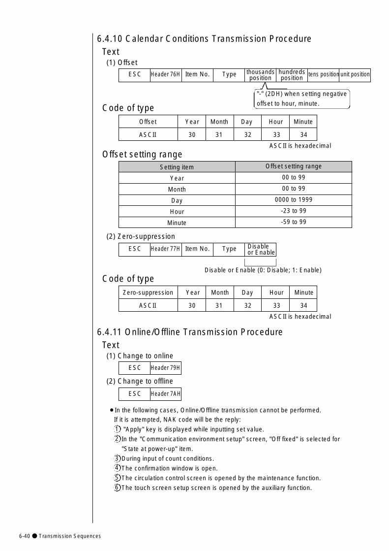
6-40● Transmission Sequences
6.4.10 Calendar Conditions Transmission ProcedureText
(1) Offset
ESC Header 76H Item No. Type thousands hundreds tens position unit positionposition position
Code of typeOffset Year Month Day Hour Minute
ASCII 30 31 32 33 34
Offset setting rangeASCII is hexadecimal
"-" (2DH) when setting negative
offset to hour, minute.
Offset setting range
00 to 99
00 to 99
0000 to 1999
-23 to 99
-59 to 99
Setting item
Year
Month
Day
Hour
Minute
(2) Zero-suppression
Code of typeZero-suppression Year Month Day Hour Minute
ASCII 30 31 32 33 34
ASCII is hexadecimal
Disable or Enable (0: Disable; 1: Enable)
ESC Header 77H Item No. Type Disable or Enable
6.4.11 Online/Offline Transmission ProcedureText
(1) Change to online
(2) Change to offline
ESC Header 79H
ESC Header 7AH
¡In the following cases, Online/Offline transmission cannot be performed.
If it is attempted, NAK code will be the reply:
"Apply" key is displayed while inputting set value.
In the "Communication environment setup" screen, "Off fixed" is selected for
"State at power-up" item.
During input of count conditions.
The confirmation window is open.
The circulation control screen is opened by the maintenance function.
The touch screen setup screen is opened by the auxiliary function.
1
2
34
5
6
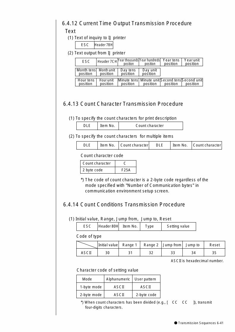
● Transmission Sequences 6-41
6.4.12 Current Time Output Transmission ProcedureText
(1) Text of inquiry to IJ printer
(2) Text output from IJ printer
ESC Header 7BH
ESC Header 7CH Year thousands Year hundreds Year tens Year unitposition position position position
Month tens Month unit Day tens Day unitposition position position position
Hour tens Hour unit Minute tens Minute unit Second tensSecond unitposition position position position position position
6.4.13 Count Character Transmission Procedure
(1) To specify the count characters for print description
(2) To specify the count characters for multiple items
DLE Item No. Count character DLE Item No. Count character
DLE Item No. Count character
Count character code
Count character C
2 byte code F25A
*) The code of count character is a 2-byte code regardless of themode specified with "Number of Communication bytes" incommunication environment setup screen.
6.4.14 Count Conditions Transmission Procedure
(1) Initial value, Range, Jump from, Jump to, Reset
Code of type
ESC Header 80H Item No. Type Setting value
*) When count characters has been divided (e.g., [ CC CC ]), transmitfour-digits characters.
Initial value Range 1 Range 2 Jump from Jump to Reset
ASCII 30 31 32 33 34 35
ASCII is hexadecimal number.
Character code of setting value
Mode Alphanumeric User pattern
1-byte mode ASCII ASCII
2-byte mode ASCII 2-byte code
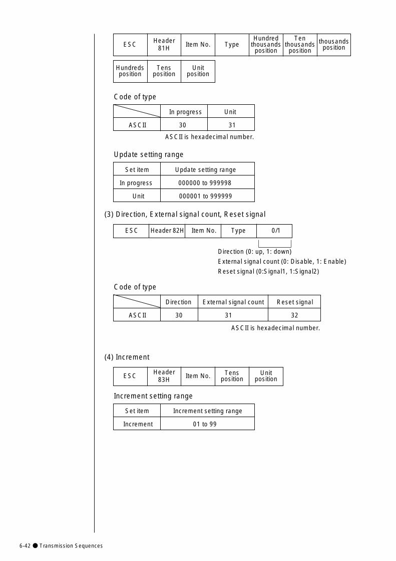
6-42● Transmission Sequences
ESC Header81H Item No. Type
Hundredthousands
position
Tenthousands
positionthousands
position
Hundredsposition
Tensposition
Unitposition
Code of type
In progress Unit
ASCII 30 31
Update setting range
Set item Update setting range
In progress 000000 to 999998
Unit 000001 to 999999
(3) Direction, External signal count, Reset signal
ESC Header 82H Item No. Type 0/1
Direction (0: up, 1: down)
External signal count (0: Disable, 1: Enable)
Reset signal (0:Signal1, 1:Signal2)
Code of type
Direction External signal count Reset signal
ASCII 30 31 32
ASCII is hexadecimal number.
ASCII is hexadecimal number.
(4) Increment
ESC Header83H Item No. Tens
positionUnit
position
Increment setting range
Set item Increment setting range
Increment 01 to 99
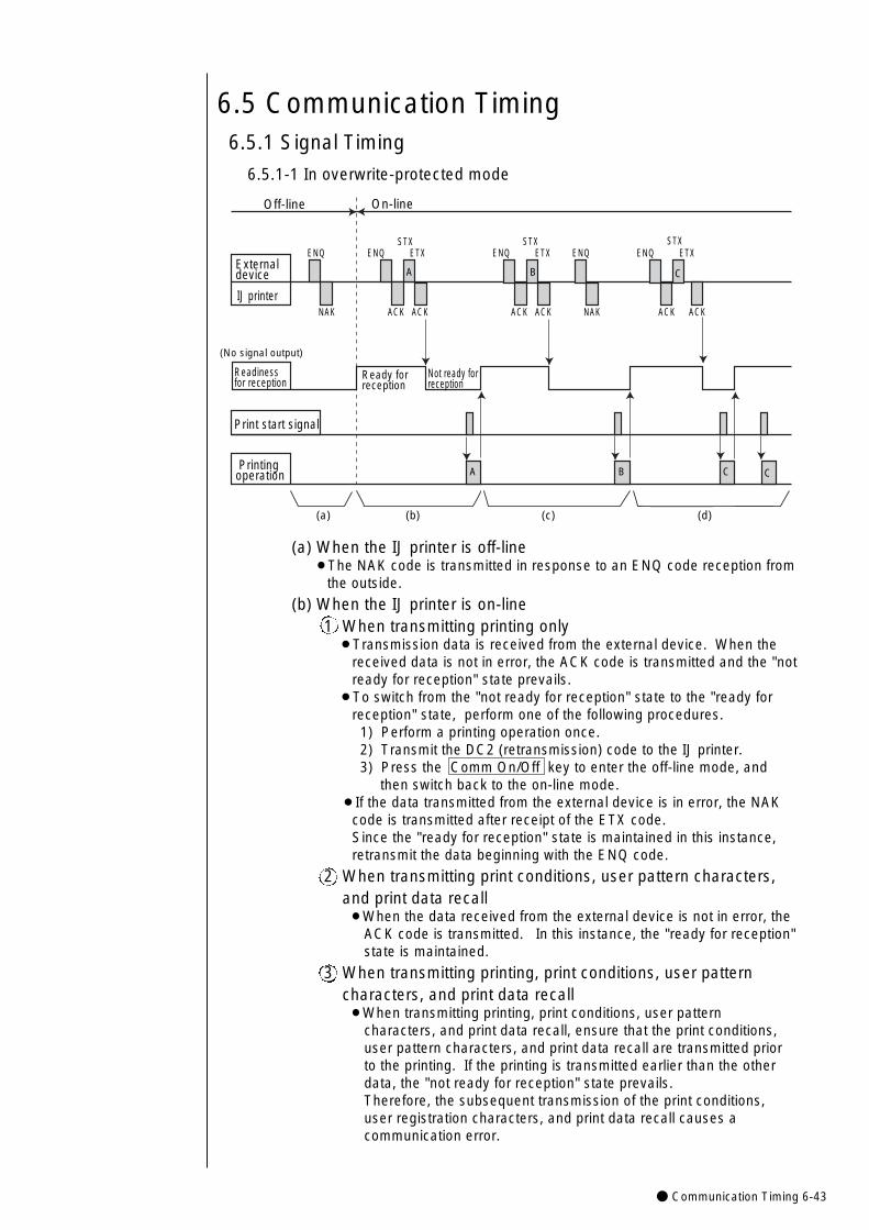
● Communication Timing 6-43
(a) When the IJ printer is off-line¡The NAK code is transmitted in response to an ENQ code reception from
the outside.
(b) When the IJ printer is on-line1 When transmitting printing only
¡Transmission data is received from the external device. When the received data is not in error, the ACK code is transmitted and the "not ready for reception" state prevails.
¡To switch from the "not ready for reception" state to the "ready for reception" state, perform one of the following procedures. 1) Perform a printing operation once. 2) Transmit the DC2 (retransmission) code to the IJ printer.3) Press the Comm On/Off key to enter the off-line mode, and
then switch back to the on-line mode.¡If the data transmitted from the external device is in error, the NAK
code is transmitted after receipt of the ETX code. Since the "ready for reception" state is maintained in this instance, retransmit the data beginning with the ENQ code.
2 When transmitting print conditions, user pattern characters, and print data recall ¡When the data received from the external device is not in error, the
ACK code is transmitted. In this instance, the "ready for reception" state is maintained.
3 When transmitting printing, print conditions, user pattern characters, and print data recall ¡When transmitting printing, print conditions, user pattern
characters, and print data recall, ensure that the print conditions, user pattern characters, and print data recall are transmitted prior to the printing. If the printing is transmitted earlier than the other data, the "not ready for reception" state prevails. Therefore, the subsequent transmission of the print conditions, user registration characters, and print data recall causes a communication error.
6.5 Communication Timing6.5.1 Signal Timing
6.5.1-1 In overwrite-protected mode
ENQENQ
NAK
ETXSTX
ACK ACK
ENQ ETXSTX
ENQ ETXSTX
ENQ
ACK ACK ACK ACKNAK
Externaldevice
IJ printer
Print start signal
Readinessfor reception
(No signal output)
Not ready forreception
Ready forreception
Printingoperation A B C C
On-lineOff-line
(a) (b) (c) (d)
A B C
6-44● Communication Timing
(c) When the "not ready for reception" state prevails after transmission data reception from the external device¡The NAK code is transmitted in response to the ENQ code reception from the
outside.
(d) Transmission data received from the external device¡Error-free transmission data is stored in the IJ printer. The same contents are
printed until different transmission data is transmitted to the IJ printer.¡If the data transmitted from the external device is in error, the IJ printer printings
remain unchanged. In such an instance, retransmit the data beginning with the ENQ code as explained in (b). The retransmission count setup must be determined from the device side.
(e) When a data transmission is aborted (the transmission of up to the ETX code is not completed)¡The IJ printer printings remain unchanged. For data retransmission, perform
either of the following procedures.(1) Transmit the DC2 (retransmission) code to the IJ printer.(2) Press the Comm On/Off key to enter the off-line mode, and then switch
back to the on-line mode.
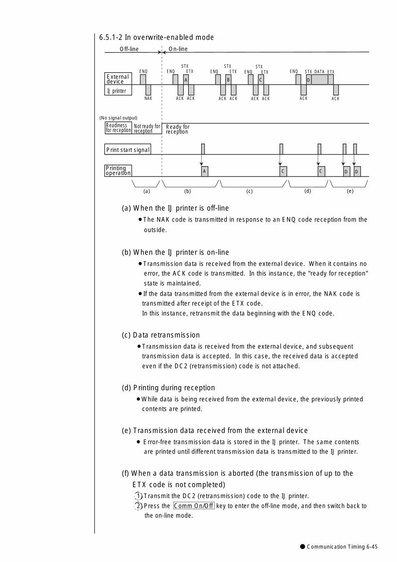
● Communication Timing 6-45
6.5.1-2 In overwrite-enabled mode
Print start signal
Readinessfor reception
(No signal output)
Not ready forreception
Printingoperation A C C D
On-lineOff-line
(a) (b) (c) (d)
D
Ready forreception
(e)
ENQENQ
NAK
ETXSTX
ACK ACK
ENQ ETXSTX
ENQ ETXSTXENQ
ACK ACK ACK ACK
External device
IJ printer
A B
ACK ACK
ETXSTX
B C D
DATA
(a) When the IJ printer is off-line
¡The NAK code is transmitted in response to an ENQ code reception from the
outside.
(b) When the IJ printer is on-line
¡Transmission data is received from the external device. When it contains no
error, the ACK code is transmitted. In this instance, the "ready for reception"
state is maintained.
¡If the data transmitted from the external device is in error, the NAK code is
transmitted after receipt of the ETX code.
In this instance, retransmit the data beginning with the ENQ code.
(c) Data retransmission
¡Transmission data is received from the external device, and subsequent
transmission data is accepted. In this case, the received data is accepted
even if the DC2 (retransmission) code is not attached.
(d) Printing during reception
¡While data is being received from the external device, the previously printed
contents are printed.
(e) Transmission data received from the external device
¡ Error-free transmission data is stored in the IJ printer. The same contents
are printed until different transmission data is transmitted to the IJ printer.
(f) When a data transmission is aborted (the transmission of up to the
ETX code is not completed)
1 Transmit the DC2 (retransmission) code to the IJ printer.
2 Press the Comm On/Off key to enter the off-line mode, and then switch back to
the on-line mode.
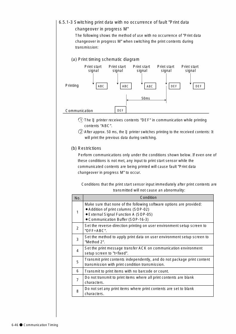
6-46● Communication Timing
6.5.1-3 Switching print data with no occurrence of fault "Print data
changeover in progress M"The following shows the method of use with no occurrence of "Print data
changeover in progress M" when switching the print contents during
transmission:
(a) Print timing schematic diagram
(b) Restrictions
Perform communications only under the conditions shown below. If even one of
these conditions is not met, any input to print start sensor while the
communicated contents are being printed will cause fault "Print data
changeover in progress M" to occur.
Conditions that the print start sensor input immediately after print contents are
transmitted will not cause an abnormality:
Printing ABC ABC DEF
50ms
ABC DEF
Communication
Print start signal
Print start signal
Print start signal
Print start signal
Print start signal
DEF
1 The IJ printer receives contents "DEF" in communication while printing
contents "ABC".
2 After approx. 50 ms, the IJ printer switches printing to the received contents: It
will print the previous data during switching.
Condition
Make sure that none of the following software options are provided:¡Addition of print columns (SOP-02)¡External Signal Function A (SOP-05)¡Communication Buffer (SOP-16-3)
Set the reverse-direction printing on user environment setup screen to "OFF=ABC".
Set the method to apply print data on user environment setup screen to "Method 2".
Set the print message transfer ACK on communication environment setup screen to "t=fixed".
Transmit print contents independently, and do not package print content transmission with print condition transmission.
Transmit to print items with no barcode or count.
Do not transmit to print items where all print contents are blank characters.
Do not set any print items where print contents are set to blank characters.
No.
1
2
3
4
5
6
7
8
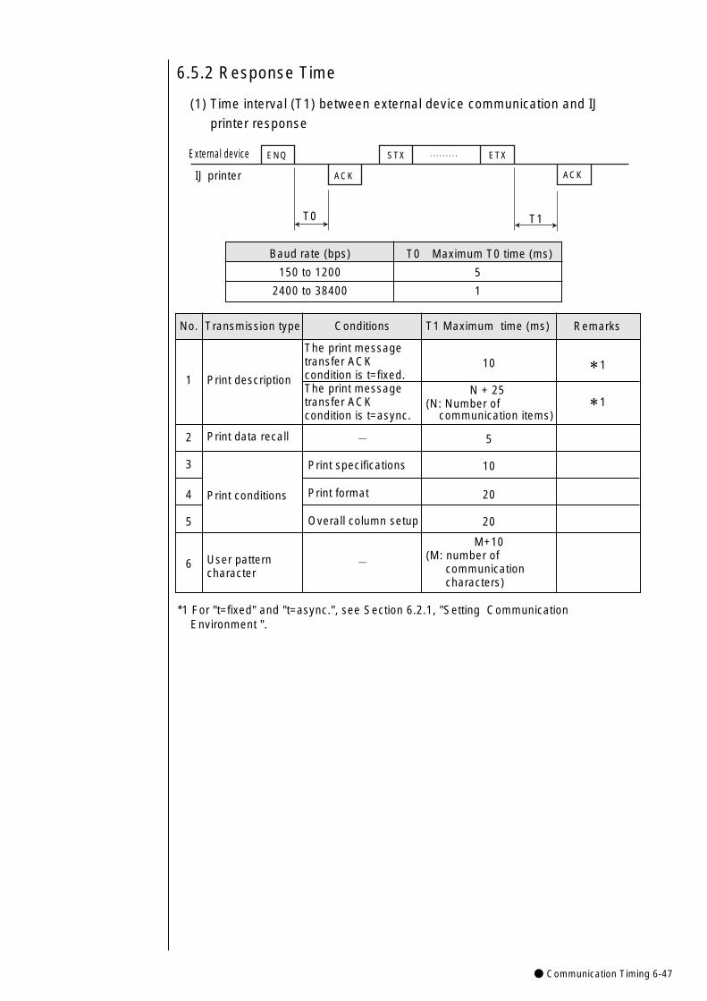
● Communication Timing 6-47
T1 Maximum time (ms)
10
N + 25(N: Number of
communication items)
5
10
20
20
M+10(M: number of
communicationcharacters)
Conditions
The print messagetransfer ACKcondition is t=fixed.The print messagetransfer ACKcondition is t=async.
-
Print specifications
Print format
Overall column setup
-
Transmission type
Print description
Print data recall
Print conditions
User pattern character
No.
1
2
3
4
5
6
Remarks
*1
*1
6.5.2 Response Time
(1) Time interval (T1) between external device communication and IJ
printer response
External device
IJ printer
ENQ
ACK
STX ETX
ACK
………
T0 T1
Baud rate (bps)
150 to 1200
2400 to 38400
T0 Maximum T0 time (ms)
5
1
*1 For "t=fixed" and "t=async.", see Section 6.2.1, "Setting Communication Environment ".
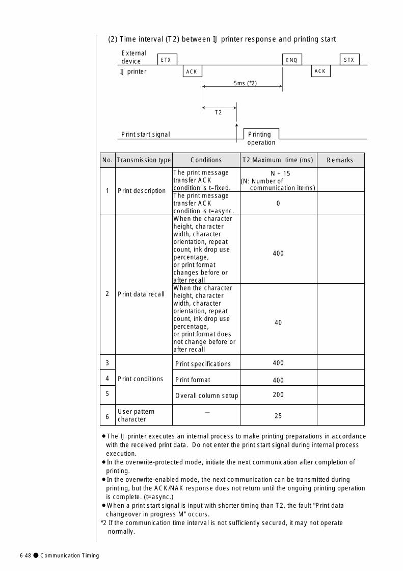
6-48● Communication Timing
External device
IJ printer
ETX
ACK
STXENQ
ACK
5ms (*2)
T2
Printing operation
Print start signal
(2) Time interval (T2) between IJ printer response and printing start
¡The IJ printer executes an internal process to make printing preparations in accordance with the received print data. Do not enter the print start signal during internal process execution.
¡In the overwrite-protected mode, initiate the next communication after completion of printing.
¡In the overwrite-enabled mode, the next communication can be transmitted during printing, but the ACK/NAK response does not return until the ongoing printing operation is complete. (t=async.)
¡When a print start signal is input with shorter timing than T2, the fault "Print data changeover in progress M" occurs.
*2 If the communication time interval is not sufficiently secured, it may not operate normally.
T2 Maximum time (ms)
N + 15(N: Number of
communication items)
0
400
40
400
400
200
25
Conditions
The print messagetransfer ACKcondition is t=fixed. The print messagetransfer ACKcondition is t=async.When the character height, characterwidth, character orientation, repeatcount, ink drop usepercentage, or print formatchanges before orafter recallWhen the characterheight, characterwidth, character orientation, repeatcount, ink drop usepercentage, or print format doesnot change before orafter recall
Print specifications
Print format
Overall column setup
-
Transmission type
Print description
Print data recall
Print conditions
User pattern character
No.
1
2
3
4
5
6
Remarks
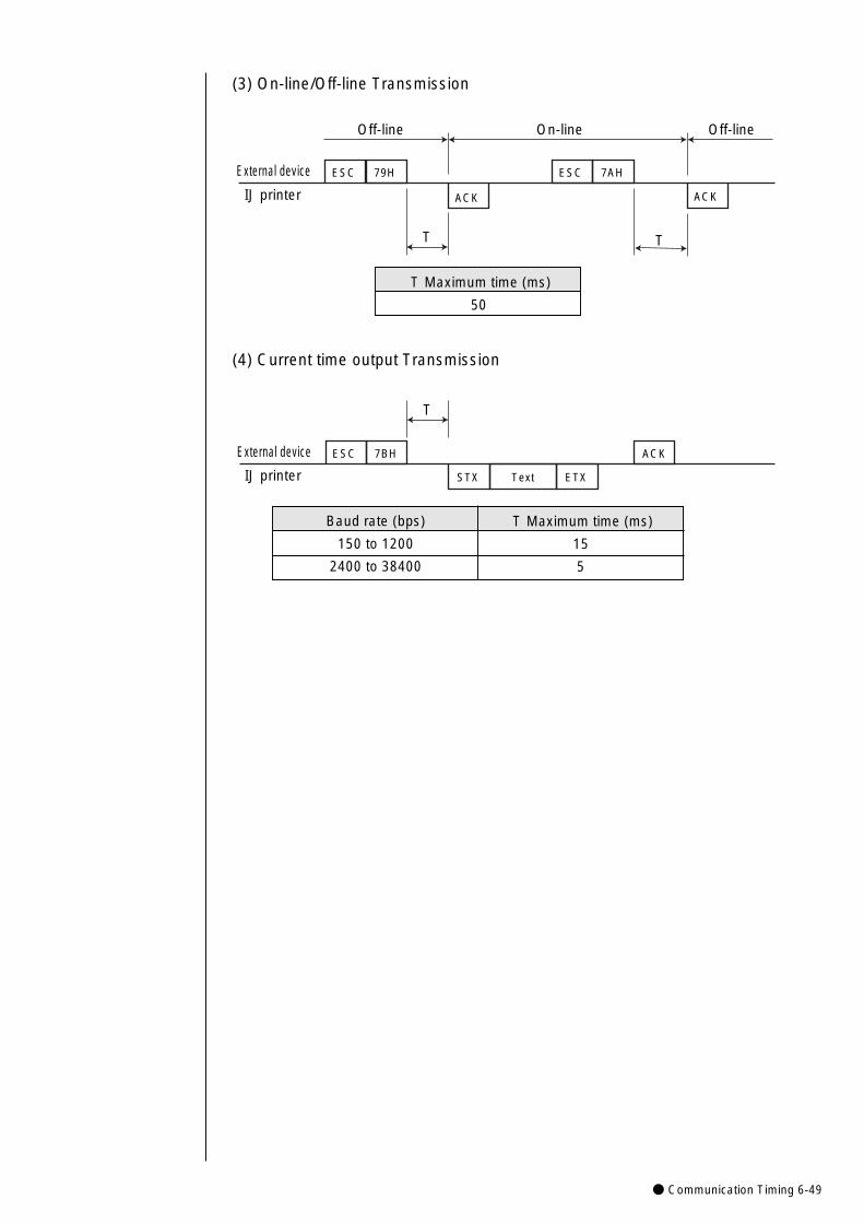
● Communication Timing 6-49
(3) On-line/Off-line Transmission
(4) Current time output Transmission
External device ESC 79H ESC 7AH
ACK ACK
T T
On-line Off-lineOff-line
IJ printer
External device
IJ printer
ESC 7BH ACK
STX Text ETX
T
Baud rate (bps)
150 to 1200
2400 to 38400
T Maximum time (ms)
15
5
T Maximum time (ms)
50

6-50● Communication Monitor Function
Item Description
Trans. External device → IJ printer: R (Receive)
IJ printer → external device: S (Send)
Communication Sended/received data are displayed in hexadecimal
description notation. Sixteen bytes of data are displayed per line.
Proc. status The current status is indicated (monitoring or interrupted).
¡The contents of serial communications between the external device and IJ printer are
displayed.
¡Up to 1500 bytes of data can be acquired at a time.
¡When you press the Start key, the system erases monitored data and acquires new data.
Item Description
StartStarts exercising the line monitor function. Erases the monitored information.
Abort Aborts the execution of the line monitor function.This switches over whether the system is to detect error-ridden locations.¡Disable: The system will not detect error-ridden
locations.The system will memorize up to Error detection bytes 1,500 of data transmitted and received.
¡Enable: The system will display error-ridden locations in ed. The system will memorize up to transmitted and received data up to the location where an error was detected.
Previous list/ Used to switch to another screen when the amount of
Next list information to be displayed is too large to fit on a single screen.
Back Returns you to the maintenance menu.
6.6 Communication Monitor Function
(1) Screen display
(2) Input keys
Trans.
R
Communication descriptionNo
1
2
3
4
5
6
7
Comm. monitor 2011.07.07 12:45
Back
Prev.list
Nextlist
S
R
S
R
S
R
05
06
02 10 31 41
32 33 34 35
06
05
06
02 10 31 41
32 33 34 35
42 43 44 45
00 00 00 00
42 43 44 45
00 00 00 00
00 00 00 00
00 03
00 00 00 00
00 03
00 10 32 31
00 AB 32 31
Proc. status: Halted
Abort
Start
Manual
Status:Ready Com=1
Blue:DLE(10), ESC(1B) Red: Failed line.
S 158
Errordetection
Startup
Shutdown
CommOn/Off
Detection [ 0 ] (0: disable 1: enable )
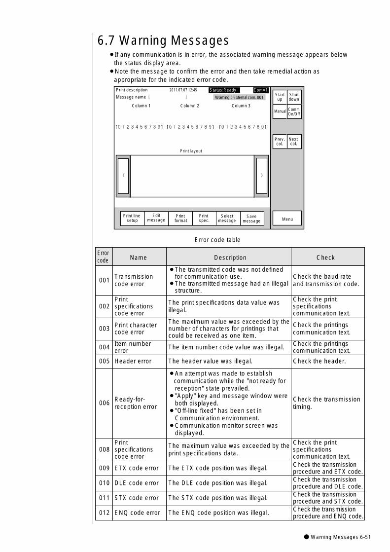
●Warning Messages 6-51
001 Transmission code error
¡The transmitted code was not definedfor communication use.
¡The transmitted message had an illegalstructure.
Check the baud rateand transmission code.
002 Print specificationscode error
The print specifications data value wasillegal.
Check the print specifications communication text.
003 Print charactercode error
The maximum value was exceeded by thenumber of characters for printings thatcould be received as one item.
Check the printingscommunication text.
004 Item number error The item number code value was illegal. Check the printings
communication text.
005 Header error The header value was illegal. Check the header.
006 Ready-for-reception error
¡An attempt was made to establish communication while the "not ready forreception" state prevailed.
¡"Apply" key and message window wereboth displayed.
¡"Off-line fixed" has been set inCommunication environment.
¡Communication monitor screen wasdisplayed.
Check the transmissiontiming.
008 Print specificationscode error
The maximum value was exceeded by theprint specifications data.
Check the print specifications communication text.
009 ETX code error The ETX code position was illegal. Check the transmissionprocedure and ETX code.
010 DLE code error The DLE code position was illegal. Check the transmissionprocedure and DLE code.
011 STX code error The STX code position was illegal. Check the transmissionprocedure and STX code.
6.7 Warning Messages¡If any communication is in error, the associated warning message appears below
the status display area.¡Note the message to confirm the error and then take remedial action as
appropriate for the indicated error code.
》《
Column 1 Column 2 Column 3
[0123456789] [0123456789] [0123456789]
Warning:External com. 001
Print layout
Print description
Message name[ ]�
2011.07.07 12:45 Status:Ready Com=1
Manual
Prev.col.
Next col.
MenuSelect
message
Startup
Shutdown
Print line setup
Editmessage
Print format
Print spec.
CommOn/Off
Savemessage
Error code table
Error Name Description Checkcode
012 ENQ code error The ENQ code position was illegal. Check the transmissionprocedure and ENQ code.
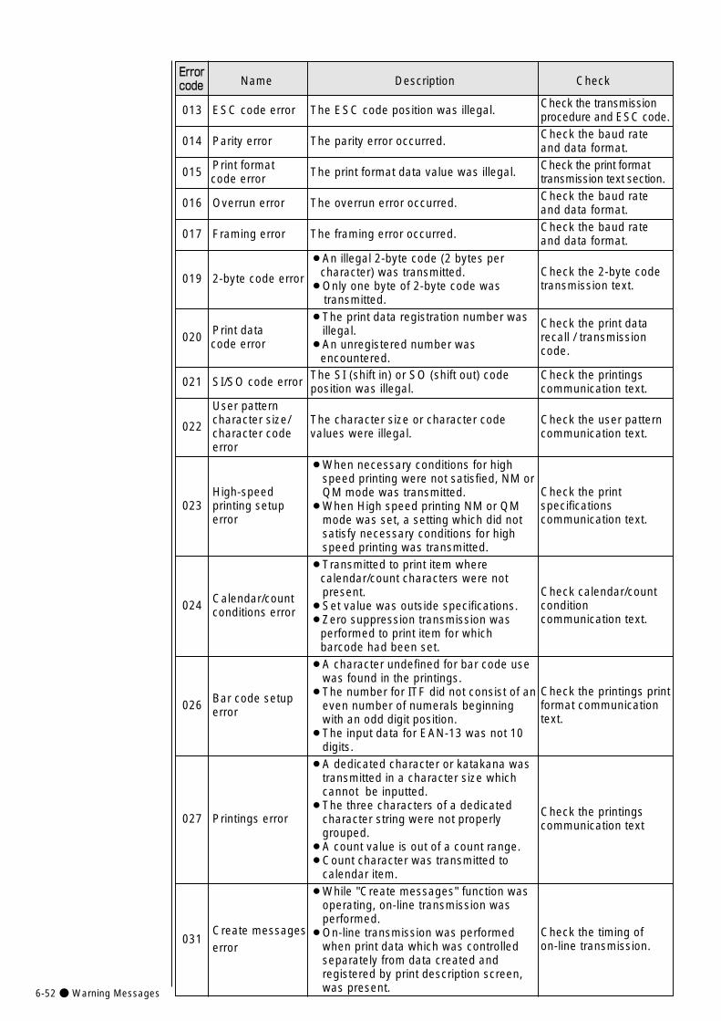
6-52●Warning Messages
ErrorName Description Checkcode
013 ESC code error The ESC code position was illegal. Check the transmissionprocedure and ESC code.
014 Parity error The parity error occurred. Check the baud rateand data format.
015 Print format code error The print format data value was illegal. Check the print format
transmission text section.
016 Overrun error The overrun error occurred. Check the baud rateand data format.
017 Framing error The framing error occurred. Check the baud rateand data format.
019 2-byte code error
¡An illegal 2-byte code (2 bytes per character) was transmitted.
¡Only one byte of 2-byte code wastransmitted.
Check the 2-byte codetransmission text.
020 Print data code error
¡The print data registration number wasillegal.
¡An unregistered number was encountered.
Check the print datarecall / transmissioncode.
021 SI/SO code error The SI (shift in) or SO (shift out) codeposition was illegal.
Check the printingscommunication text.
022
User pattern character size/character codeerror
The character size or character code values were illegal.
Check the user patterncommunication text.
023 High-speed printing setuperror
¡When necessary conditions for highspeed printing were not satisfied, NM orQM mode was transmitted.
¡When High speed printing NM or QMmode was set, a setting which did notsatisfy necessary conditions for highspeed printing was transmitted.
Check the print specifications communication text.
024 Calendar/count conditions error
¡Transmitted to print item where calendar/count characters were notpresent.
¡Set value was outside specifications.¡Zero suppression transmission was
performed to print item for which barcode had been set.
Check calendar/count condition communication text.
026 Bar code setuperror
¡A character undefined for bar code usewas found in the printings.
¡The number for ITF did not consist of aneven number of numerals beginningwith an odd digit position.
¡The input data for EAN-13 was not 10digits.
Check the printings printformat communicationtext.
027 Printings error
¡A dedicated character or katakana wastransmitted in a character size whichcannot be inputted.
¡The three characters of a dedicatedcharacter string were not properlygrouped.
¡A count value is out of a count range.¡Count character was transmitted to
calendar item.
Check the printingscommunication text
031 Create messageserror
¡While "Create messages" function wasoperating, on-line transmission wasperformed.
¡On-line transmission was performedwhen print data which was controlledseparately from data created andregistered by print description screen,was present.
Check the timing of on-line transmission.

● Precaution 6-53
6.8 Precautions
6.8.1 Notes on Product speed matching Feature Use
(1) If the product speed matching signal cannot be entered during printing,
the printing state continues to prevail so that communication may not
be established (no response can be made).
If such a situation is encountered, perform procedure 1 or 2 below.
1 Enter the standby state and then initiate the communication.
2 Issue the print abort code "DC3". After the IJ printer returns an
"ACK" response, perform the normal procedure to initiate the
communication.(2) Number of pulses necessary for a rotary encoder from print signal
detection until the start of printing.Number of pulses necessary = Number of printing preparation pulses
( 1 ) + Print start delay.1 Number of printing preparation pulses = A / 1 scan time
Use an integer by rounding up the fractional portion.
6.8.2 Notes on Print Condition Transmission(1) The number of digits for character height data is 2 by default. However,
the preceding IJ printer models GX and HX use 3 digits by default for print condition transmission (optional function). If the new model of the IJ printer is used as a replacement for such a predecessor, open the following screen from the communication environment setup screen and change the number of digits for character height data to 3.
Comm.env.setup 2011.07.07 12:45 Status:Ready Com=0
Manual
Showcursor
Prev.set-tings
Nextset-tings
Startup
Shutdown
CommOn/Off
Print message transfer ACK [2] (1: t=fixed 2: t=async. )
Print spec. transfer char. height [1] (0: 2 digits 1: 3 dights )
Communication and signal error [0] (0: Warning 1: Fault)
¡Character height (when the 3-digit data format is chosen)
ESC Header 30H Hundreds Tens Units position position position
Character height (000 to 099)
NOTE: If the value is within the range from 100 to 999, an error occurs.
1 scan time =(Vertical dot count + character width setting) X Ink drop use percentage
Excitation frequency (kHz)(ms)
nozzle diameter65μm40μm
100μm
Value of A7710

7-1● Circulation System Operating and Adjustment Procedures
¡Never drain the ink or makeup ink waste solution into public sewer systems.Waste disposal must comply with all appropriate regulations.Consult theappropriate regulatory agency for further imformation.
¡Exercise care not to inadvertently disconnect, forcibly pull, or bend a piping tube.Since the ink and makeup ink in some portions of piping tubes are pressurized,they may splash and enter your eyes or mouth or soil your hands or clothing.If the ink or makeup ink, enters your eyes or mouth, immediately flush with warmor cold water and see a physician.
¡When charging a refill of ink or makeup ink, exchanging ink, or otherwisehandling ink or makeup ink, take enough care not to spill ink or makeup ink. If youspill any ink or makeup ink by mistake, wipe it off neatly and promptly with wipingpaper or something similar. Do not close the maintenance cover until you makesure that the portion you have just wiped is completely dry. You must pay particular attention when you have spilled ink or makeup ink insidethe printer and it is not completely dry. Why? Because vapors of ink or makeupink will stay inside the printer and may catch on or cause a fire.
If you find it hard to wipe the printer when energized, stop it with the maintenancecover open. Power it down, then wipe it off again.
¡Should you find a leak of ink or makeup ink inside the printer while the printer isrunning or being maintained, wipe it off promptly with wiping paper or somethingsimilar. Then, with the maintenance cover open, stop the printer, power it down,and repair the leak.
A continued run with a leak of ink or makeup ink will cause an anomaly, resultingin abnormal printing. Ink and makeup ink are flammable. They may therefore catch on or cause a fire.
¡If you wish to receive ink drops in a beaker, for a printing test for example, use anelectrically conductive beaker and connect the beaker securely to the ground. Do not let the tip of the printing head enter the beaker.
Ink drops used for printing are electrically charged. An ungrounded beaker has agradually rising charge, possibly catching on or causing a fire.
WARNING
¡When handling the ink or makeup ink, which contatins organic solvent, observethe following precautions.
Wear protective gloves and safety goggles to avoid direct skin contact. If skin is contacted, thoroughly clean it with soap and warm or cold water.When transferring the ink or makeup ink to or from a bottle, exercise care notto let it come into contact with the printer or surrounding articles. If anything iscontacted, wipe it clean with a cloth moistened with ethyl alcohol.Notice that there is a possibility that a cap and a content may fly with innerpressure when opening the container of ink and a solvent.Please open a cap of container an even place.
CAUTION
7. Circulation System Operating and Adjustment Procedures
3
2
1
4
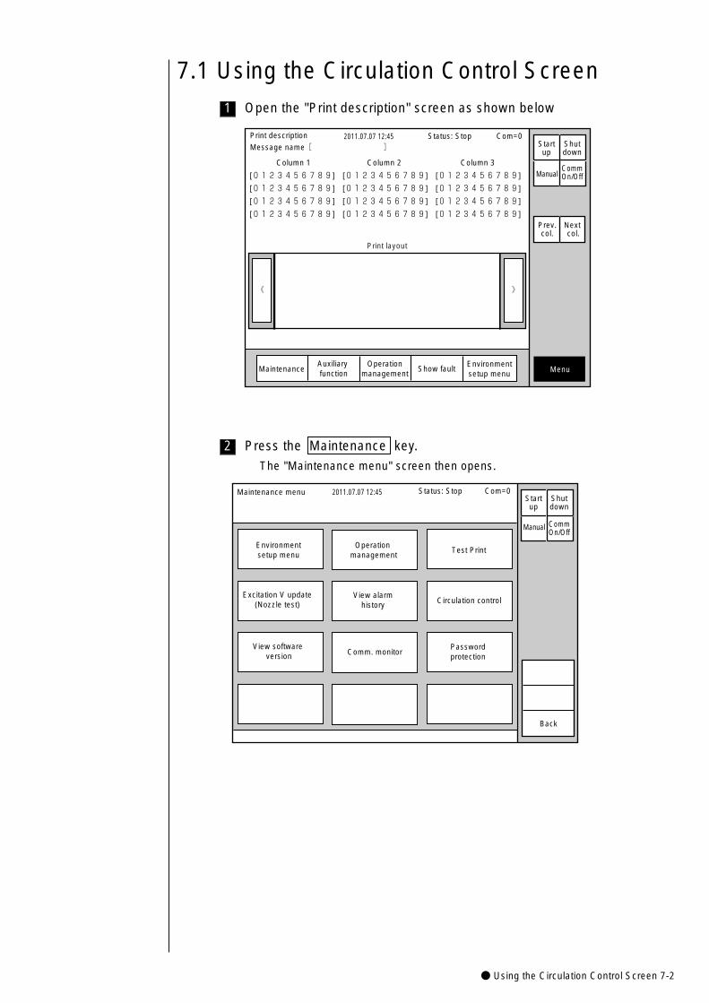
● Using the Circulation Control Screen 7-2
2
1
7.1 Using the Circulation Control ScreenOpen the "Print description" screen as shown below
》《
Column 1 Column 2 Column 3
[0123456789] [0123456789] [0123456789]
[0123456789] [0123456789] [0123456789]
[0123456789] [0123456789] [0123456789]
[0123456789] [0123456789] [0123456789]
Print description 2011.07.07 12:45Message name[ ] Start
upShutdown
ManualCommOn/Off
Print layout
Status: Stop Com=0
Prev.col.
Next col.
MaintenanceAuxiliary function
Show fault MenuOperation
managementEnvironmentsetup menu
Press the Maintenance key.
The "Maintenance menu" screen then opens.
Maintenance menu 2011.07.07 12:45
Environmentsetup menu
Operation management
Test Print
Excitation V update(Nozzle test)
View software version
View alarmhistory Circulation control
Passwordprotection
Comm. monitor
Back
Manual
Status: Stop Com=0 Startup
Shutdown
CommOn/Off

7-3● Using the Circulation Control Screen
4
3 Press the Circulation control key.
The "Circulation control" screen then opens.
Firtst menu
Circulation control 2011.07.07 12:45
Cancel
Process afterlong-term shutdown
Ink replacement
Nozzle backwash
Process prior tolong-term shutdown
Ink circulation
Gutter cleaning
Makeup ink refill
Eject ink(Goes to standby)
Cleaning stop No-cleaning stop
Start/Continue
Select option; press [Start/Cont.] Proc. status:
Status: Stop
Ink filterreplacement
Prev.menu
Next menu
Circulation control 2011.07.07 12:45
Cancel
Circulation systemenvironment setup
Pressure relief
Parts usage timemanagement
Ink streamalignment
Ink drainage Ink refill
Start/Continue
Select option; press [Start/Cont.] Proc. status:
Status: Stop
Prev.menu
Next menu
Second menu
Press the key for an execution target item and the Start/Continue
key in sequence.
¡When, for instance, executing the "Nozzle backwash" function, press
the Nozzle backwash and Start/Continue keys in sequence.
¡If you have pressed a wrong key, press the Cancel key.
¡To switch between the first menu and second menu, use the Prev. ,
Next keys.
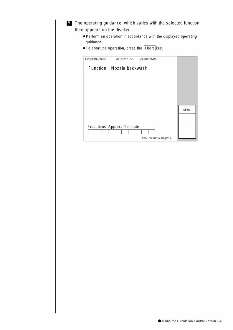
● Using the Circulation Control Screen 7-4
5 The operating guidance, which varies with the selected function,
then appears on the display.
¡Perform an operation in accordance with the displayed operating
guidance.
¡To abort the operation, press the Abort key.
Circulation control 20011.07.07 12:45
Proc. status: In progress.
Function:Nozzle backwash
Proc. time: Approx. 1 minute
Status:Service
Abort
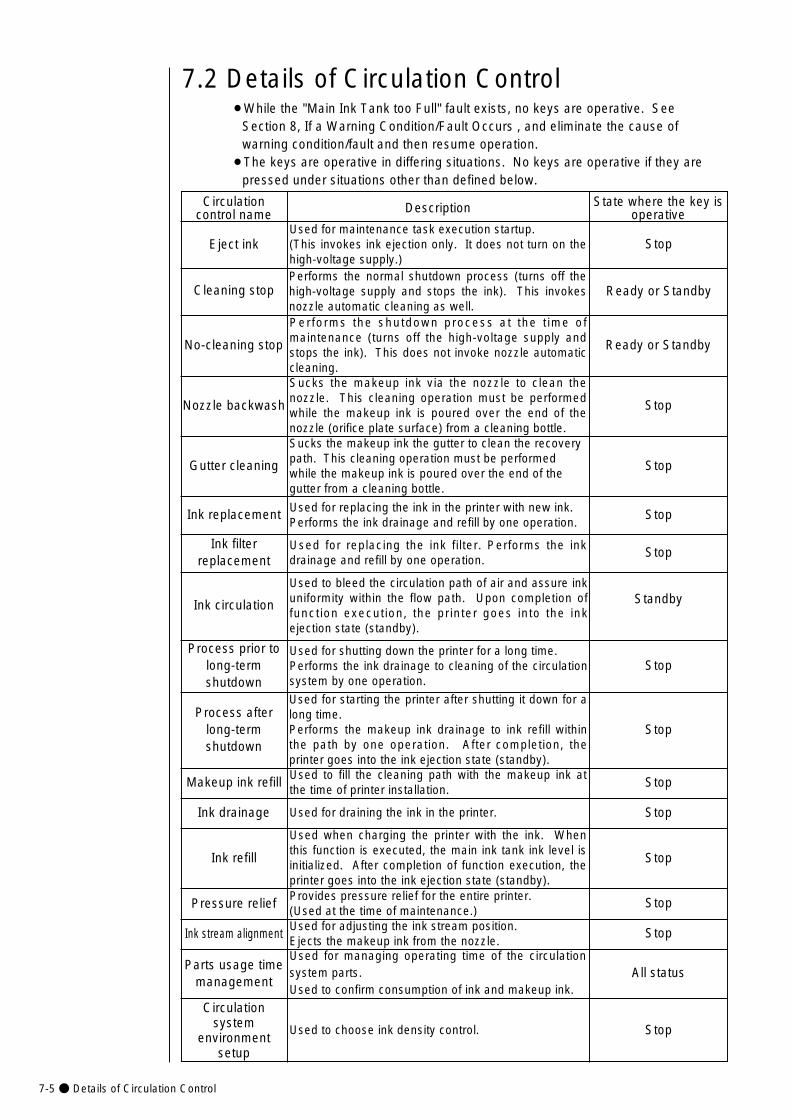
7-5● Details of Circulation Control
State where the key isoperative
Circulationcontrol name Description
Eject inkUsed for maintenance task execution startup. (This invokes ink ejection only. It does not turn on thehigh-voltage supply.)
Cleaning stopPerforms the normal shutdown process (turns off thehigh-voltage supply and stops the ink). This invokesnozzle automatic cleaning as well.
No-cleaning stop
Performs the shutdown process at the t ime ofmaintenance (turns off the high-voltage supply andstops the ink). This does not invoke nozzle automaticcleaning.
Ink refill
Used when charging the printer with the ink. Whenthis function is executed, the main ink tank ink level isinitialized. After completion of function execution, theprinter goes into the ink ejection state (standby).
Ink circulation
Used to bleed the circulation path of air and assure inkuniformity within the flow path. Upon completion offunction execution, the printer goes into the inkejection state (standby).
Nozzle backwash
Sucks the makeup ink via the nozzle to clean thenozzle. This cleaning operation must be performedwhile the makeup ink is poured over the end of thenozzle (orifice plate surface) from a cleaning bottle.
Gutter cleaning
Sucks the makeup ink the gutter to clean the recoverypath. This cleaning operation must be performedwhile the makeup ink is poured over the end of thegutter from a cleaning bottle.
Pressure reliefProvides pressure relief for the entire printer. (Used at the time of maintenance.)
Makeup ink refillUsed to fill the cleaning path with the makeup ink atthe time of printer installation.
7.2 Details of Circulation Control
Stop
Ready or Standby
Ready or Standby
Stop
Standby
Process prior tolong-termshutdown
Used for shutting down the printer for a long time.Performs the ink drainage to cleaning of the circulationsystem by one operation.
Stop
Process afterlong-termshutdown
Used for starting the printer after shutting it down for along time.Performs the makeup ink drainage to ink refill withinthe path by one operation. After completion, theprinter goes into the ink ejection state (standby).
Stop
Stop
Stop
Ink replacement Used for replacing the ink in the printer with new ink.Performs the ink drainage and refill by one operation.
Stop
Ink filterreplacement
Used for replacing the ink filter. Performs the inkdrainage and refill by one operation.
Stop
Stop
Ink stream alignmentUsed for adjusting the ink stream position.Ejects the makeup ink from the nozzle.
Stop
Stop
Ink drainage Used for draining the ink in the printer. Stop
¡While the "Main Ink Tank too Full" fault exists, no keys are operative. See Section 8, If a Warning Condition/Fault Occurs , and eliminate the cause of warning condition/fault and then resume operation.
¡The keys are operative in differing situations. No keys are operative if they are pressed under situations other than defined below.
Circulationsystem
environmentsetup
Used to choose ink density control.
Parts usage timemanagement
Used for managing operating time of the circulationsystem parts.Used to confirm consumption of ink and makeup ink.
Stop
All status
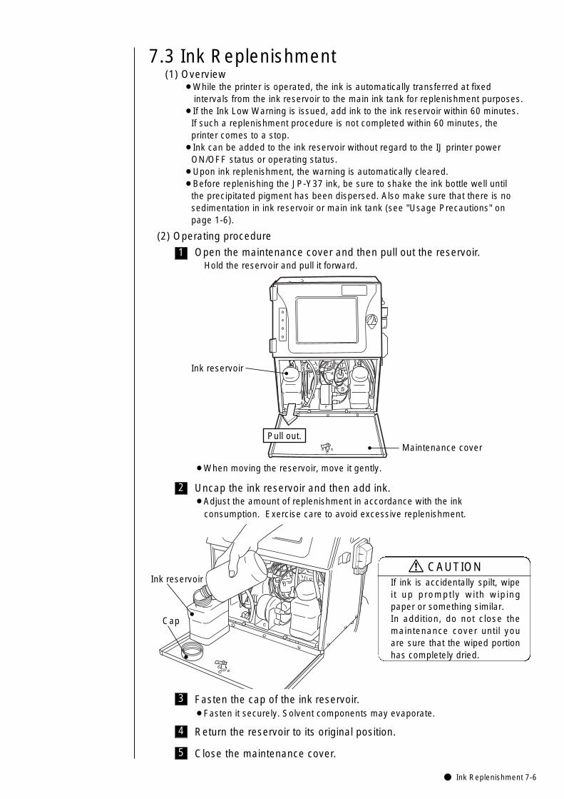
● Ink Replenishment 7-6
5
4
3
2
1
7.3 Ink Replenishment(1) Overview
¡While the printer is operated, the ink is automatically transferred at fixed intervals from the ink reservoir to the main ink tank for replenishment purposes.
¡If the Ink Low Warning is issued, add ink to the ink reservoir within 60 minutes.If such a replenishment procedure is not completed within 60 minutes, the printer comes to a stop.
¡Ink can be added to the ink reservoir without regard to the IJ printer power ON/OFF status or operating status.
¡Upon ink replenishment, the warning is automatically cleared.¡Before replenishing the JP-Y37 ink, be sure to shake the ink bottle well until
the precipitated pigment has been dispersed. Also make sure that there is no sedimentation in ink reservoir or main ink tank (see "Usage Precautions" on page 1-6).
(2) Operating procedure
Open the maintenance cover and then pull out the reservoir.Hold the reservoir and pull it forward.
Uncap the ink reservoir and then add ink.¡Adjust the amount of replenishment in accordance with the ink
consumption. Exercise care to avoid excessive replenishment.
¡When moving the reservoir, move it gently.
Ink reservoir
Maintenance coverPull out.
Ink reservoir
Cap
Fasten the cap of the ink reservoir.¡Fasten it securely. Solvent components may evaporate.
Return the reservoir to its original position.
Close the maintenance cover.
If ink is accidentally spilt, wipeit up promptly with wipingpaper or something similar. In addition, do not close themaintenance cover until youare sure that the wiped portionhas completely dried.
CAUTION
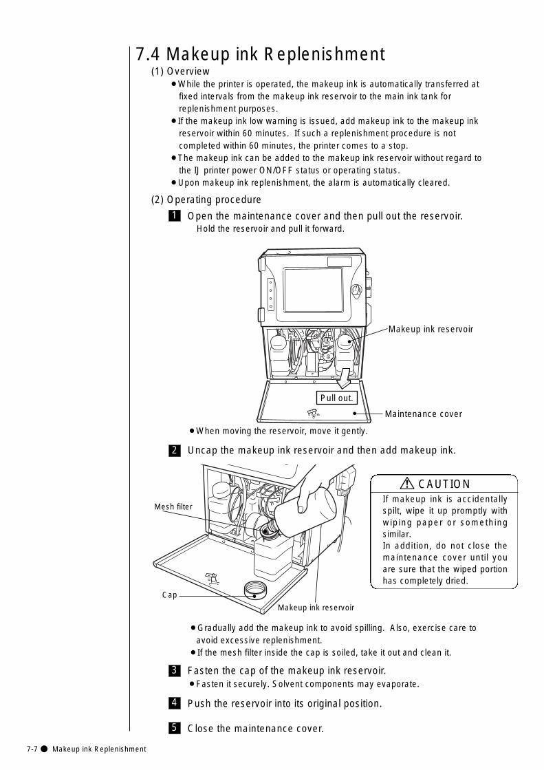
7-7● Makeup ink Replenishment
5
4
3
2
1
7.4 Makeup ink Replenishment
Open the maintenance cover and then pull out the reservoir.Hold the reservoir and pull it forward.
Uncap the makeup ink reservoir and then add makeup ink.
Fasten the cap of the makeup ink reservoir.¡Fasten it securely. Solvent components may evaporate.
Makeup ink reservoir
Mesh filter
Cap
¡When moving the reservoir, move it gently.
¡Gradually add the makeup ink to avoid spilling. Also, exercise care to avoid excessive replenishment.
¡If the mesh filter inside the cap is soiled, take it out and clean it.
Pull out.
Makeup ink reservoir
Maintenance cover
Push the reservoir into its original position.
Close the maintenance cover.
(1) Overview¡While the printer is operated, the makeup ink is automatically transferred at
fixed intervals from the makeup ink reservoir to the main ink tank forreplenishment purposes.
¡If the makeup ink low warning is issued, add makeup ink to the makeup ink reservoir within 60 minutes. If such a replenishment procedure is not completed within 60 minutes, the printer comes to a stop.
¡The makeup ink can be added to the makeup ink reservoir without regard to the IJ printer power ON/OFF status or operating status.
¡Upon makeup ink replenishment, the alarm is automatically cleared.
(2) Operating procedure
If makeup ink is accidentallyspilt, wipe it up promptly withwiping paper or somethingsimilar. In addition, do not close themaintenance cover until youare sure that the wiped portionhas completely dried.
CAUTION
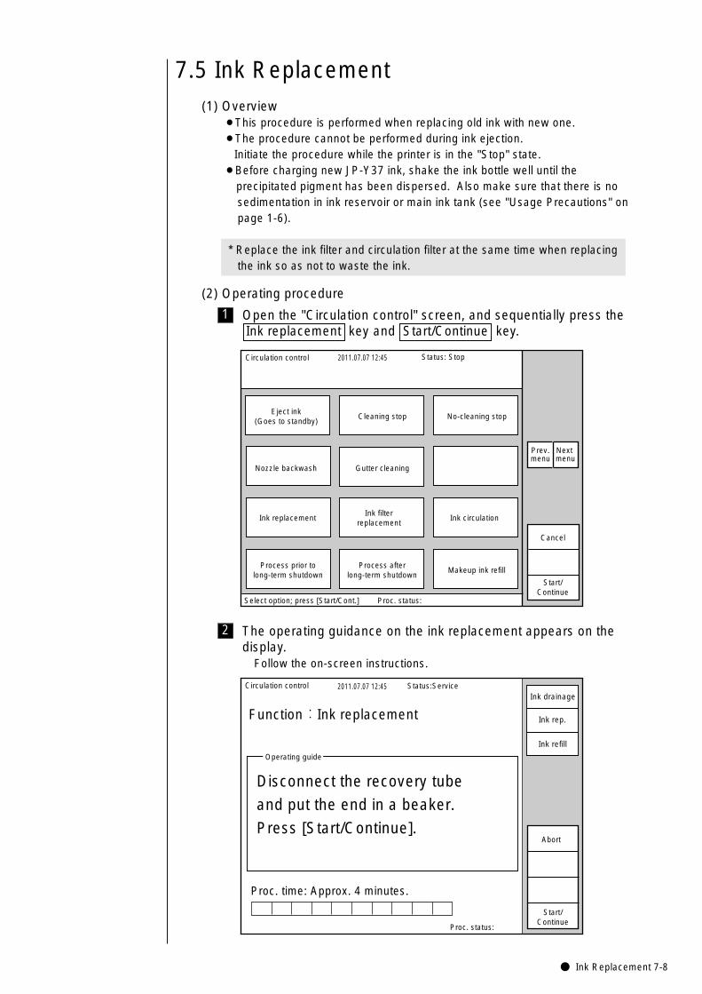
● Ink Replacement 7-8
7.5 Ink Replacement(1) Overview
¡This procedure is performed when replacing old ink with new one.¡The procedure cannot be performed during ink ejection.
Initiate the procedure while the printer is in the "Stop" state.¡Before charging new JP-Y37 ink, shake the ink bottle well until the
precipitated pigment has been dispersed. Also make sure that there is no sedimentation in ink reservoir or main ink tank (see "Usage Precautions" on page 1-6).
* Replace the ink filter and circulation filter at the same time when replacing the ink so as not to waste the ink.
(2) Operating procedure
1
Circulation control 2011.07.07 12:45
Cancel
Process afterlong-term shutdown
Ink replacement
Nozzle backwash
Process prior tolong-term shutdown
Ink circulation
Gutter cleaning
Makeup ink refill
Eject ink(Goes to standby)
Cleaning stop No-cleaning stop
Start/Continue
Select option; press [Start/Cont.] Proc. status:
Status: Stop
Ink filterreplacement
Prev.menu
Next menu
Open the "Circulation control" screen, and sequentially press theInk replacement key and Start/Continue key.
2
Circulation control 2011.07.07 12:45
Proc. status:
Function:Ink replacement
Proc. time: Approx. 4 minutes.
Operating guide
Disconnect the recovery tube
and put the end in a beaker.
Press [Start/Continue].
Status:Service
Start/Continue
Abort
Ink drainage
Ink rep.
Ink refill
The operating guidance on the ink replacement appears on thedisplay.
Follow the on-screen instructions.
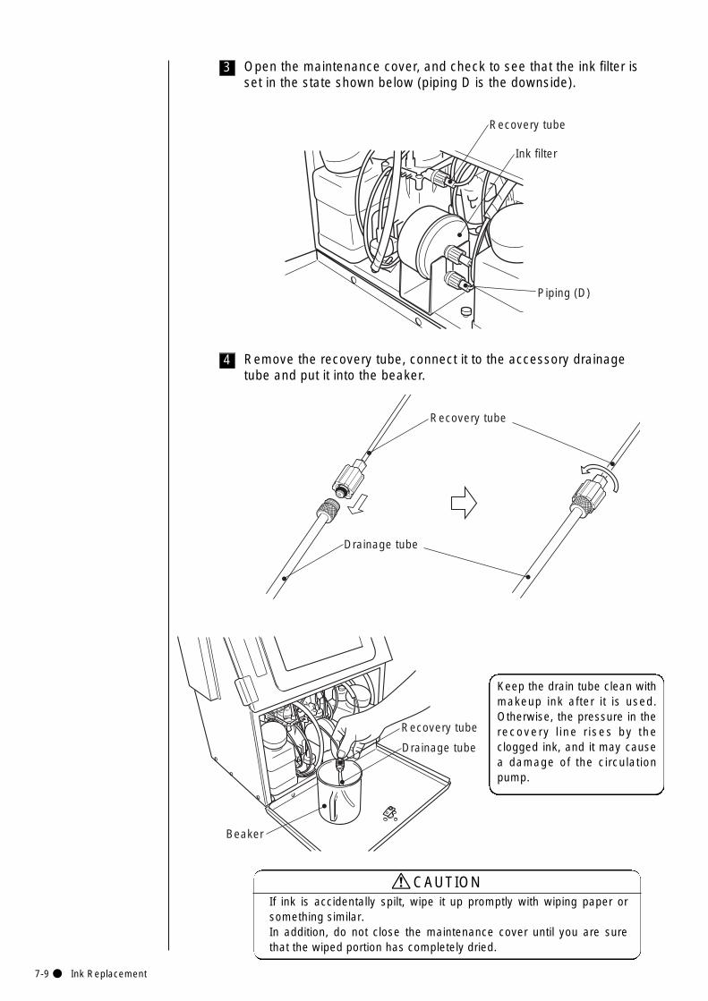
7-9● Ink Replacement
3
Piping (D)
Recovery tube
Ink filter
Open the maintenance cover, and check to see that the ink filter isset in the state shown below (piping D is the downside).
4
Recovery tube
Drainage tube
Remove the recovery tube, connect it to the accessory drainagetube and put it into the beaker.
If ink is accidentally spilt, wipe it up promptly with wiping paper orsomething similar. In addition, do not close the maintenance cover until you are surethat the wiped portion has completely dried.
CAUTION
Keep the drain tube clean withmakeup ink after it is used.Otherwise, the pressure in therecovery l ine rises by theclogged ink, and it may causea damage of the circulationpump.
Recovery tube
Drainage tube
Beaker
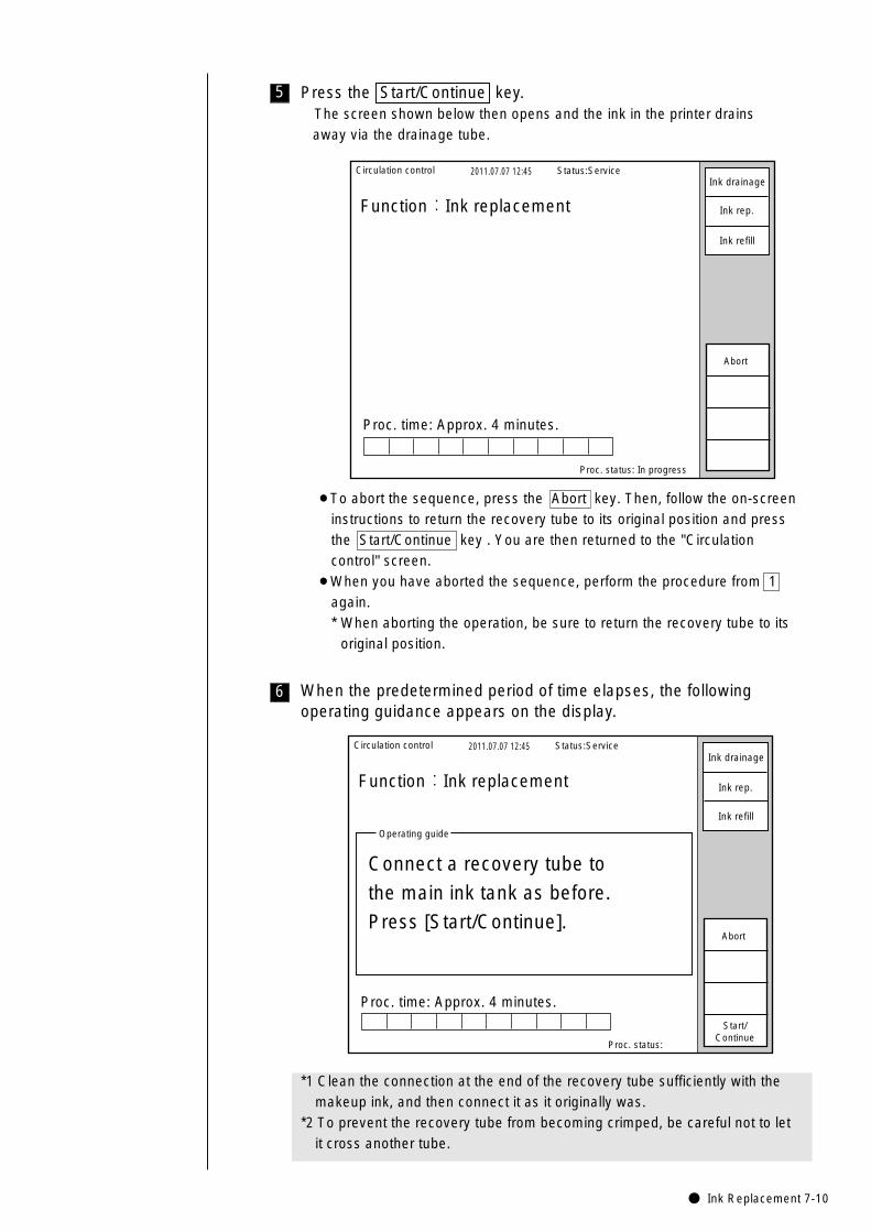
● Ink Replacement 7-10
6
5 Press the Start/Continue key.The screen shown below then opens and the ink in the printer drains away via the drainage tube.
Circulation control 2011.07.07 12:45
Proc. status: In progress
Function:Ink replacement
Proc. time: Approx. 4 minutes.
Status:Service
Abort
Ink drainage
Ink rep.
Ink refill
When the predetermined period of time elapses, the followingoperating guidance appears on the display.
¡To abort the sequence, press the Abort key. Then, follow the on-screeninstructions to return the recovery tube to its original position and pressthe Start/Continue key . You are then returned to the "Circulationcontrol" screen.
¡When you have aborted the sequence, perform the procedure from 1again.* When aborting the operation, be sure to return the recovery tube to its
original position.
Circulation control 2011.07.07 12:45
Proc. status:
Function:Ink replacement
Operating guide
Connect a recovery tube to
the main ink tank as before.
Press [Start/Continue].
Status:Service
Start/Continue
Abort
Ink drainage
Ink rep.
Ink refill
Proc. time: Approx. 4 minutes.
*1 Clean the connection at the end of the recovery tube sufficiently with themakeup ink, and then connect it as it originally was.
*2 To prevent the recovery tube from becoming crimped, be careful not to letit cross another tube.
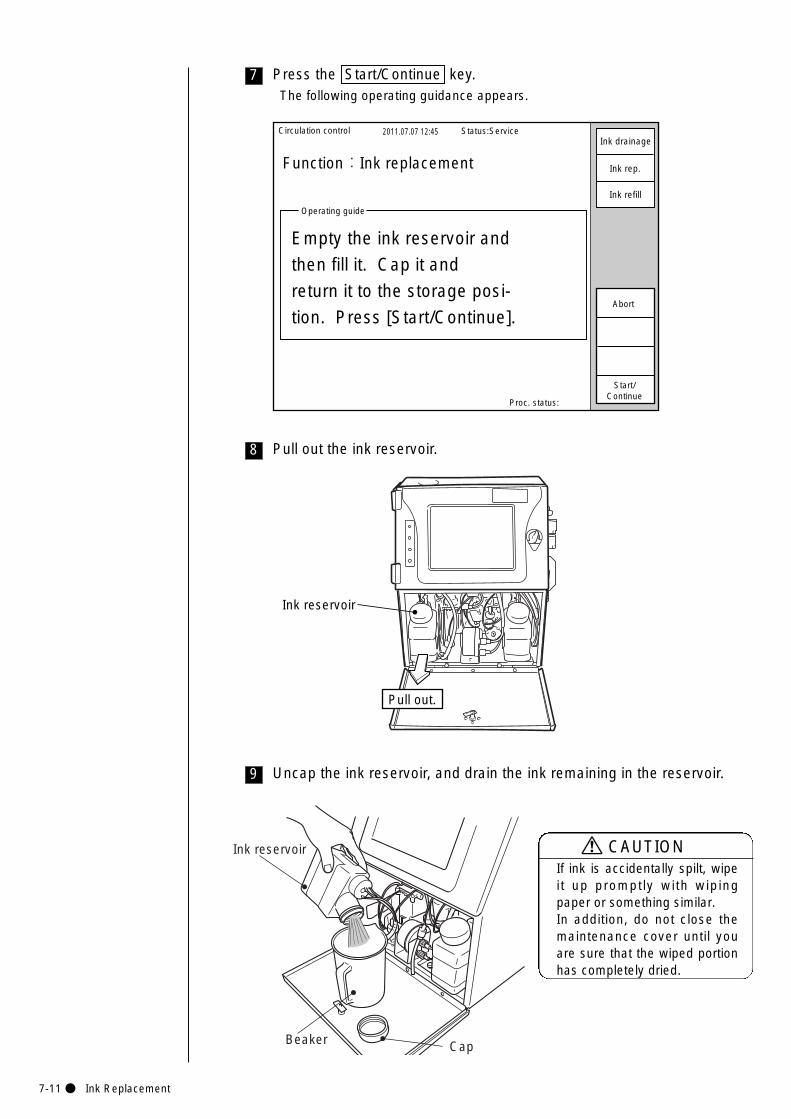
7-11● Ink Replacement
8 Pull out the ink reservoir.
Ink reservoir
Pull out.
9 Uncap the ink reservoir, and drain the ink remaining in the reservoir.
Cap
Ink reservoir
Beaker
Circulation control 2011.07.07 12:45
Proc. status:
Function:Ink replacement
Operating guide
Empty the ink reservoir and
then fill it. Cap it and
return it to the storage posi-
tion. Press [Start/Continue].
Status:Service
Start/Continue
Abort
Ink drainage
Ink rep.
Ink refill
7 Press the Start/Continue key.The following operating guidance appears.
If ink is accidentally spilt, wipeit up promptly with wipingpaper or something similar. In addition, do not close themaintenance cover until youare sure that the wiped portionhas completely dried.
CAUTION
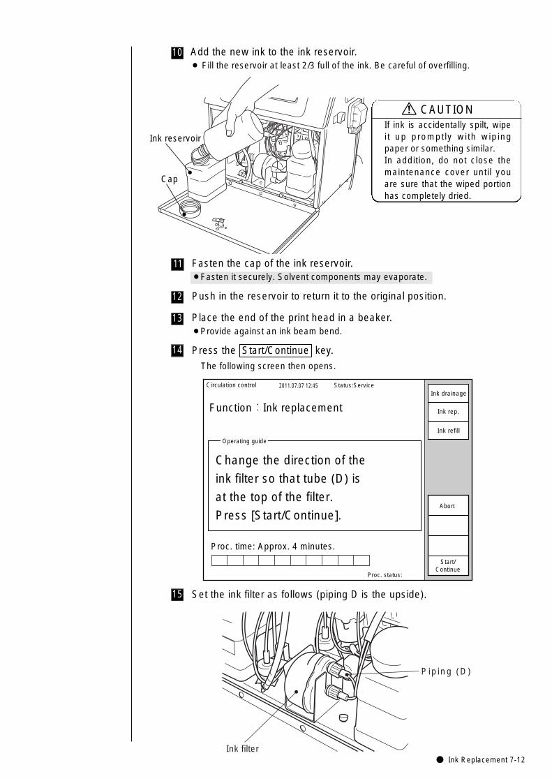
● Ink Replacement 7-12
12 Push in the reservoir to return it to the original position.
14 Press the Start/Continue key.
The following screen then opens.
Circulation control 2011.07.07 12:45
Proc. status:
Function:Ink replacement
Proc. time: Approx. 4 minutes.
Operating guide
Change the direction of the
ink filter so that tube (D) is
at the top of the filter.
Press [Start/Continue].
Status:Service
Start/Continue
Abort
Ink drainage
Ink rep.
Ink refill
15 Set the ink filter as follows (piping D is the upside).
Piping (D)
Ink filter
11 Fasten the cap of the ink reservoir.¡Fasten it securely. Solvent components may evaporate.
10 Add the new ink to the ink reservoir.¡ Fill the reservoir at least 2/3 full of the ink. Be careful of overfilling.
Ink reservoir
Cap
If ink is accidentally spilt, wipeit up promptly with wipingpaper or something similar. In addition, do not close themaintenance cover until youare sure that the wiped portionhas completely dried.
CAUTION
13 Place the end of the print head in a beaker.¡Provide against an ink beam bend.
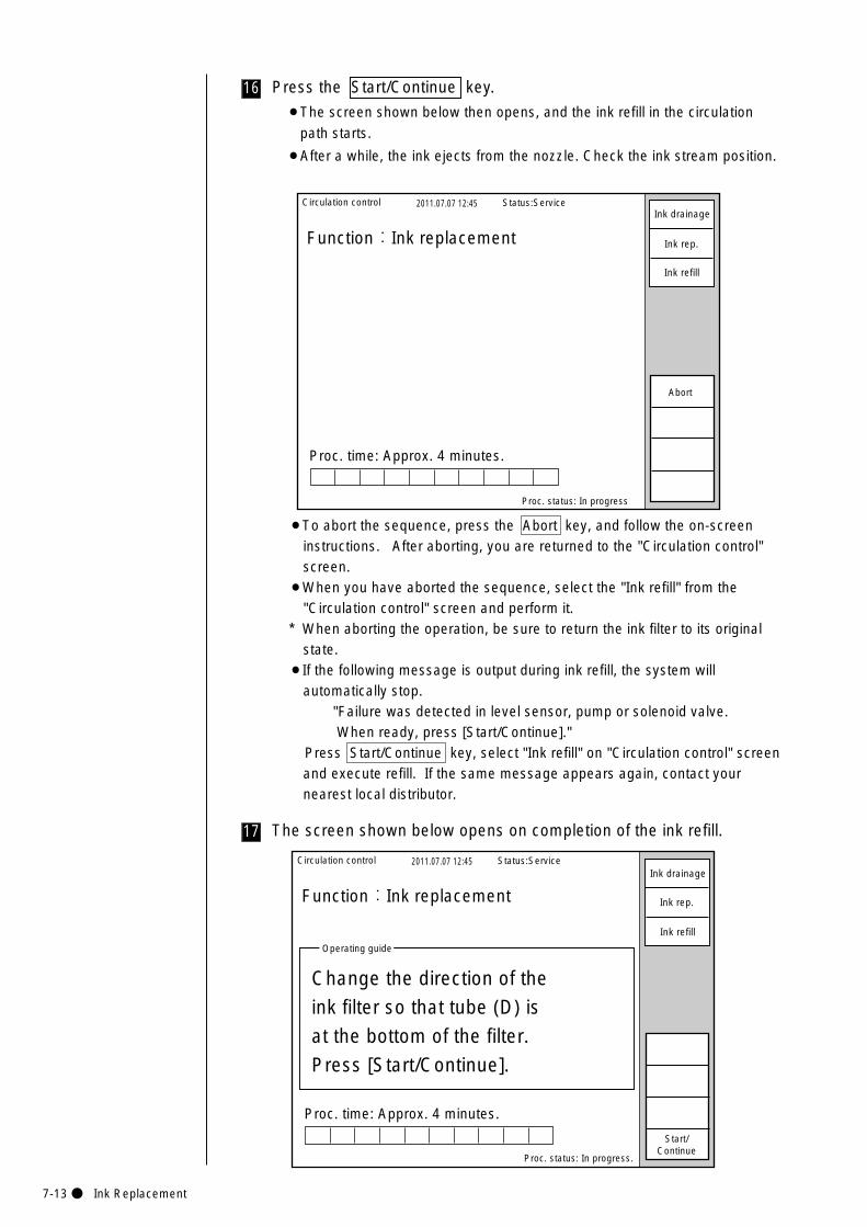
7-13● Ink Replacement
16 Press the Start/Continue key.
¡The screen shown below then opens, and the ink refill in the circulation
path starts.
¡After a while, the ink ejects from the nozzle. Check the ink stream position.
Circulation control 2011.07.07 12:45
Proc. status: In progress
Function:Ink replacement
Proc. time: Approx. 4 minutes.
Status:Service
Abort
Ink drainage
Ink rep.
Ink refill
17 The screen shown below opens on completion of the ink refill.
¡To abort the sequence, press the Abort key, and follow the on-screeninstructions. After aborting, you are returned to the "Circulation control"screen.
¡When you have aborted the sequence, select the "Ink refill" from the"Circulation control" screen and perform it.
* When aborting the operation, be sure to return the ink filter to its originalstate.
¡If the following message is output during ink refill, the system willautomatically stop.
"Failure was detected in level sensor, pump or solenoid valve. When ready, press [Start/Continue]."
Press Start/Continue key, select "Ink refill" on "Circulation control" screenand execute refill. If the same message appears again, contact yournearest local distributor.
Circulation control 2011.07.07 12:45
Proc. status: In progress.
Function:Ink replacement
Proc. time: Approx. 4 minutes.
Operating guide
Change the direction of the
ink filter so that tube (D) is
at the bottom of the filter.
Press [Start/Continue].
Status:Service
Start/Continue
Ink drainage
Ink rep.
Ink refill
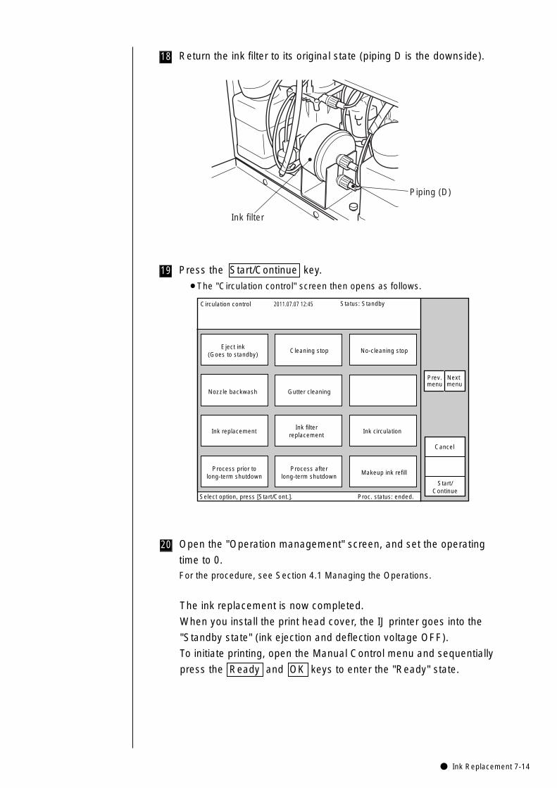
● Ink Replacement 7-14
19
18 Return the ink filter to its original state (piping D is the downside).
Piping (D)
Ink filter
Press the Start/Continue key.
¡The "Circulation control" screen then opens as follows.
Circulation control 2011.07.07 12:45
Cancel
Process afterlong-term shutdown
Ink replacement
Nozzle backwash
Process prior tolong-term shutdown
Ink circulation
Gutter cleaning
Makeup ink refill
Eject ink(Goes to standby)
Cleaning stop No-cleaning stop
Start/Continue
Select option, press [Start/Cont.]. Proc. status: ended.
Status: Standby
Ink filterreplacement
Prev.menu
Next menu
The ink replacement is now completed.
When you install the print head cover, the IJ printer goes into the
"Standby state" (ink ejection and deflection voltage OFF).
To initiate printing, open the Manual Control menu and sequentially
press the Ready and OK keys to enter the "Ready" state.
20 Open the "Operation management" screen, and set the operating
time to 0.For the procedure, see Section 4.1 Managing the Operations.
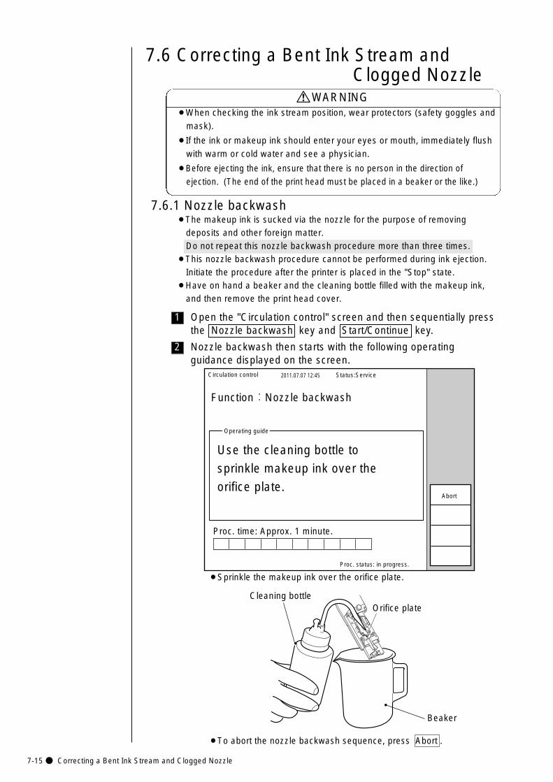
7-15● Correcting a Bent Ink Stream and Clogged Nozzle
2
1
7.6 Correcting a Bent Ink Stream and Clogged Nozzle
7.6.1 Nozzle backwash
Open the "Circulation control" screen and then sequentially pressthe Nozzle backwash key and Start/Continue key.
Nozzle backwash then starts with the following operatingguidance displayed on the screen.
Circulation control 2011.07.07 12:45
Proc. status: in progress.
Function:Nozzle backwash
Proc. time: Approx. 1 minute.
Operating guide
Use the cleaning bottle to
sprinkle makeup ink over the
orifice plate.
Status:Service
Abort
¡To abort the nozzle backwash sequence, press Abort .
¡When checking the ink stream position, wear protectors (safety goggles and
mask).
¡If the ink or makeup ink should enter your eyes or mouth, immediately flush
with warm or cold water and see a physician.
¡Before ejecting the ink, ensure that there is no person in the direction of
ejection. (The end of the print head must be placed in a beaker or the like.)
WARNING
¡The makeup ink is sucked via the nozzle for the purpose of removing deposits and other foreign matter. Do not repeat this nozzle backwash procedure more than three times.
¡This nozzle backwash procedure cannot be performed during ink ejection. Initiate the procedure after the printer is placed in the "Stop" state.
¡Have on hand a beaker and the cleaning bottle filled with the makeup ink, and then remove the print head cover.
Cleaning bottle
Beaker
Orifice plate
¡Sprinkle the makeup ink over the orifice plate.
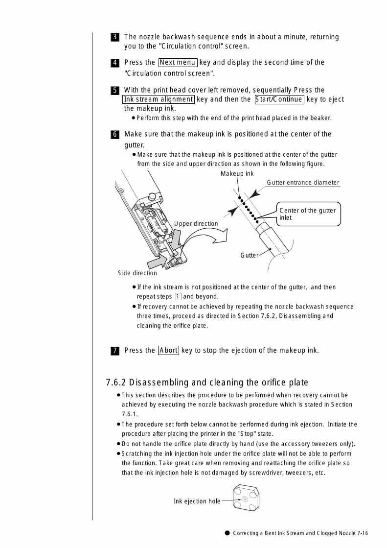
● Correcting a Bent Ink Stream and Clogged Nozzle 7-16
¡This section describes the procedure to be performed when recovery cannot be
achieved by executing the nozzle backwash procedure which is stated in Section
7.6.1.
¡The procedure set forth below cannot be performed during ink ejection. Initiate the
procedure after placing the printer in the "Stop" state.
¡Do not handle the orifice plate directly by hand (use the accessory tweezers only).
¡Scratching the ink injection hole under the orifice plate will not be able to perform
the function. Take great care when removing and reattaching the orifice plate so
that the ink injection hole is not damaged by screwdriver, tweezers, etc.
7.6.2 Disassembling and cleaning the orifice plate
6
5
4
3 The nozzle backwash sequence ends in about a minute, returningyou to the "Circulation control" screen.
Press the Next menu key and display the second time of the
"Circulation control screen".
With the print head cover left removed, sequentially Press the Ink stream alignment key and then the Start/Continue key to ejectthe makeup ink.¡Perform this step with the end of the print head placed in the beaker.
Make sure that the makeup ink is positioned at the center of the
gutter.¡Make sure that the makeup ink is positioned at the center of the gutter
from the side and upper direction as shown in the following figure.
Gutter
Makeup ink
Center of the gutterinlet
Side direction
Upper direction
Gutter entrance diameter
¡If the ink stream is not positioned at the center of the gutter, and then
repeat steps 1 and beyond.
¡If recovery cannot be achieved by repeating the nozzle backwash sequence
three times, proceed as directed in Section 7.6.2, Disassembling and
cleaning the orifice plate.
7 Press the Abort key to stop the ejection of the makeup ink.
Ink ejection hole
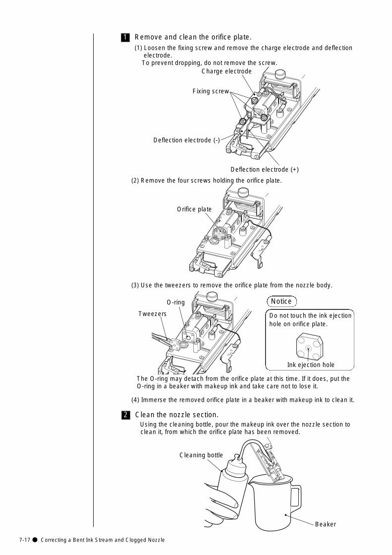
7-17● Correcting a Bent Ink Stream and Clogged Nozzle
1 Remove and clean the orifice plate.(1) Loosen the fixing screw and remove the charge electrode and deflection
electrode. To prevent dropping, do not remove the screw.
(2) Remove the four screws holding the orifice plate.
Deflection electrode (+)
Deflection electrode (-)
Charge electrode
Fixing screw
Orifice plate
(3) Use the tweezers to remove the orifice plate from the nozzle body.
Tweezers
O-ring
The O-ring may detach from the orifice plate at this time. If it does, put the O-ring in a beaker with makeup ink and take care not to lose it.
(4) Immerse the removed orifice plate in a beaker with makeup ink to clean it.
Ink ejection hole
Notice
Do not touch the ink ejectionhole on orifice plate.
Cleaning bottle
Beaker
2 Clean the nozzle section.Using the cleaning bottle, pour the makeup ink over the nozzle section to clean it, from which the orifice plate has been removed.
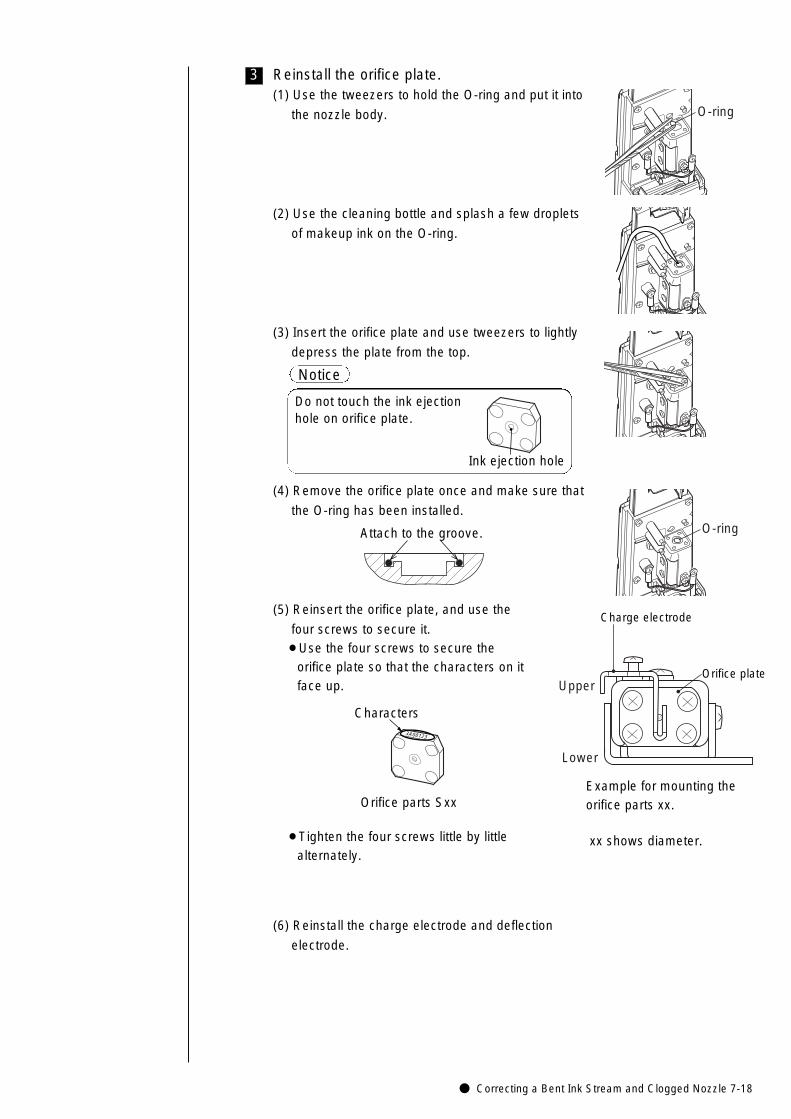
● Correcting a Bent Ink Stream and Clogged Nozzle 7-18
3 Reinstall the orifice plate.
O-ring
O-ring
(1) Use the tweezers to hold the O-ring and put it into
the nozzle body.
(2) Use the cleaning bottle and splash a few droplets
of makeup ink on the O-ring.
(3) Insert the orifice plate and use tweezers to lightly
depress the plate from the top.
(4) Remove the orifice plate once and make sure that
the O-ring has been installed.
(5) Reinsert the orifice plate, and use the
four screws to secure it.¡Use the four screws to secure the
orifice plate so that the characters on it face up.
¡Tighten the four screws little by little alternately.
(6) Reinstall the charge electrode and deflection
electrode.
Orifice plate
Charge electrode
Upper
Lower
Ink ejection hole
Notice
Do not touch the ink ejectionhole on orifice plate.
Attach to the groove.
3A00123
Characters
Orifice parts SxxExample for mounting theorifice parts xx.
xx shows diameter.
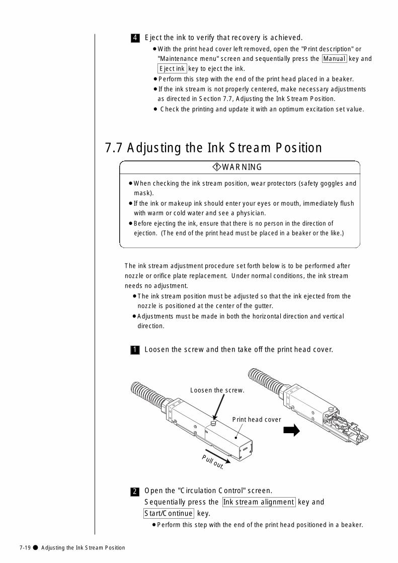
7-19● Adjusting the Ink Stream Position
2
1
7.7 Adjusting the Ink Stream Position
Loosen the screw and then take off the print head cover.
The ink stream adjustment procedure set forth below is to be performed after
nozzle or orifice plate replacement. Under normal conditions, the ink stream
needs no adjustment.
¡The ink stream position must be adjusted so that the ink ejected from the
nozzle is positioned at the center of the gutter.
¡Adjustments must be made in both the horizontal direction and vertical
direction.
¡When checking the ink stream position, wear protectors (safety goggles and
mask).
¡If the ink or makeup ink should enter your eyes or mouth, immediately flush
with warm or cold water and see a physician.
¡Before ejecting the ink, ensure that there is no person in the direction of
ejection. (The end of the print head must be placed in a beaker or the like.)
WARNING
Open the "Circulation Control" screen.
Sequentially press the Ink stream alignment key and
Start/Continue key.
¡Perform this step with the end of the print head positioned in a beaker.
Pull out.
Loosen the screw.
Print head cover
4 Eject the ink to verify that recovery is achieved.
¡With the print head cover left removed, open the "Print description" or
"Maintenance menu" screen and sequentially press the Manual key and
Eject ink key to eject the ink.
¡Perform this step with the end of the print head placed in a beaker.
¡If the ink stream is not properly centered, make necessary adjustments
as directed in Section 7.7, Adjusting the Ink Stream Position.
¡ Check the printing and update it with an optimum excitation set value.
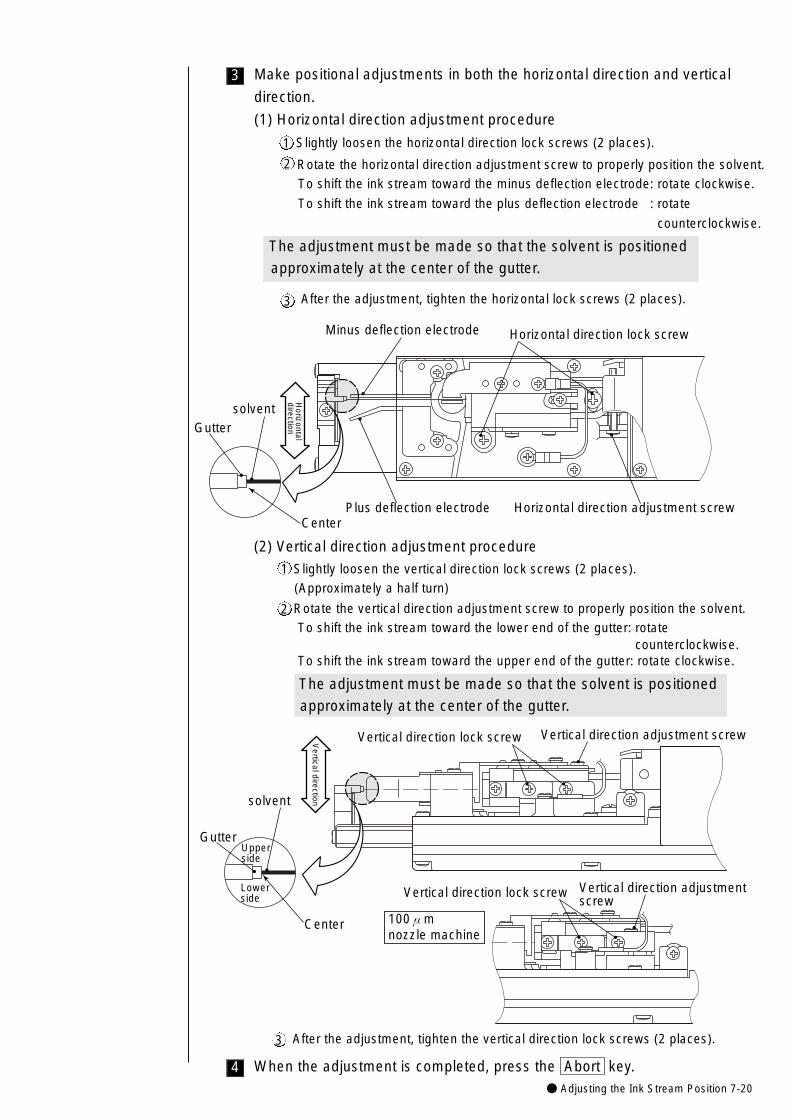
● Adjusting the Ink Stream Position 7-20
Make positional adjustments in both the horizontal direction and vertical
direction.
(1) Horizontal direction adjustment procedure
Slightly loosen the horizontal direction lock screws (2 places).
Rotate the horizontal direction adjustment screw to properly position the solvent.
To shift the ink stream toward the minus deflection electrode: rotate clockwise.
To shift the ink stream toward the plus deflection electrode : rotate
counterclockwise.
The adjustment must be made so that the solvent is positioned
approximately at the center of the gutter.
3
After the adjustment, tighten the horizontal lock screws (2 places).
(2) Vertical direction adjustment procedure
Slightly loosen the vertical direction lock screws (2 places).
(Approximately a half turn)
Rotate the vertical direction adjustment screw to properly position the solvent.
To shift the ink stream toward the lower end of the gutter: rotate counterclockwise.
To shift the ink stream toward the upper end of the gutter: rotate clockwise.
The adjustment must be made so that the solvent is positioned
approximately at the center of the gutter.
Horizontal direction lock screw
Plus deflection electrode Horizontal direction adjustment screw
Minus deflection electrode
Horizontal
direction
solventGutter
Center
1
2
3
1
2
After the adjustment, tighten the vertical direction lock screws (2 places).3
Vertical direction
Vertical direction lock screw Vertical direction adjustment screw
Upperside
Lowerside
solvent
Gutter
Center
Vertical direction lock screw Vertical direction adjustment screw
100μm nozzle machine
When the adjustment is completed, press the Abort key.4
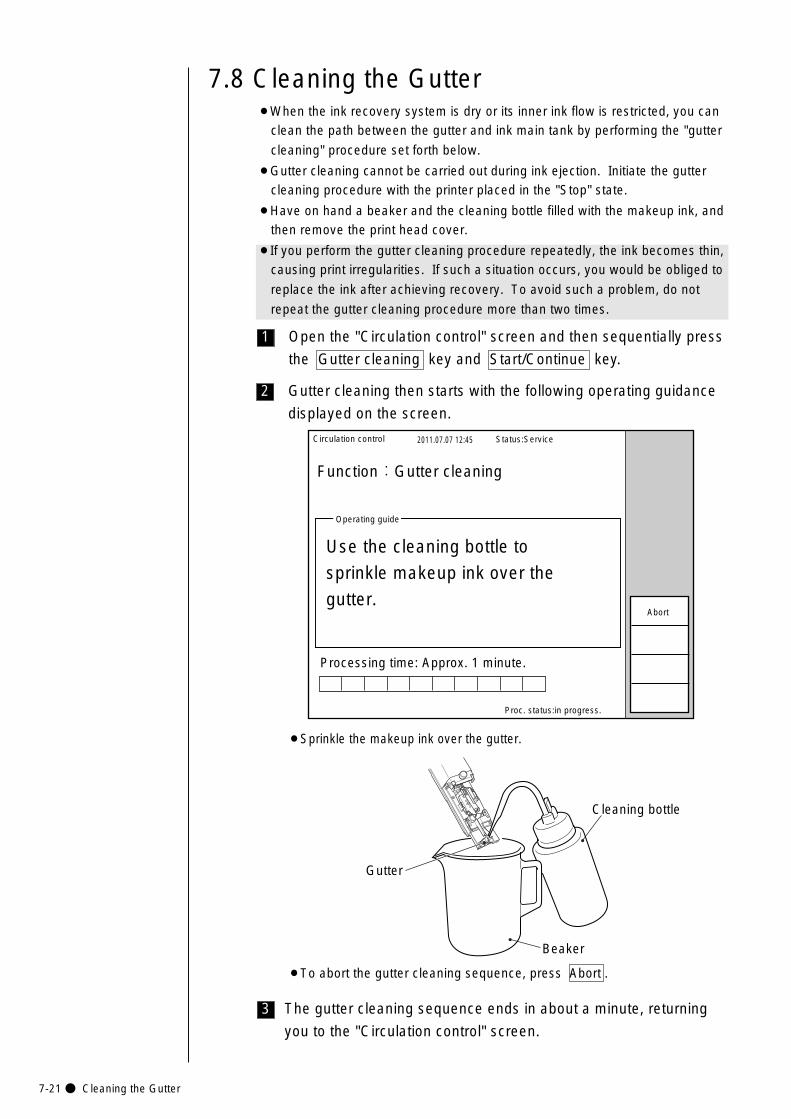
7-21● Cleaning the Gutter
3
2
1
7.8 Cleaning the Gutter¡When the ink recovery system is dry or its inner ink flow is restricted, you can
clean the path between the gutter and ink main tank by performing the "gutter
cleaning" procedure set forth below.
¡Gutter cleaning cannot be carried out during ink ejection. Initiate the gutter
cleaning procedure with the printer placed in the "Stop" state.
¡Have on hand a beaker and the cleaning bottle filled with the makeup ink, and
then remove the print head cover.
¡If you perform the gutter cleaning procedure repeatedly, the ink becomes thin,
causing print irregularities. If such a situation occurs, you would be obliged to
replace the ink after achieving recovery. To avoid such a problem, do not
repeat the gutter cleaning procedure more than two times.
Open the "Circulation control" screen and then sequentially press
the Gutter cleaning key and Start/Continue key.
Circulation control 2011.07.07 12:45
Proc. status:in progress.
Function:Gutter cleaning
Processing time: Approx. 1 minute.
Operating guide
Use the cleaning bottle to
sprinkle makeup ink over the
gutter.
Status:Service
Abort
¡To abort the gutter cleaning sequence, press Abort .
Gutter cleaning then starts with the following operating guidance
displayed on the screen.
Cleaning bottle
Gutter
Beaker
The gutter cleaning sequence ends in about a minute, returning
you to the "Circulation control" screen.
¡Sprinkle the makeup ink over the gutter.
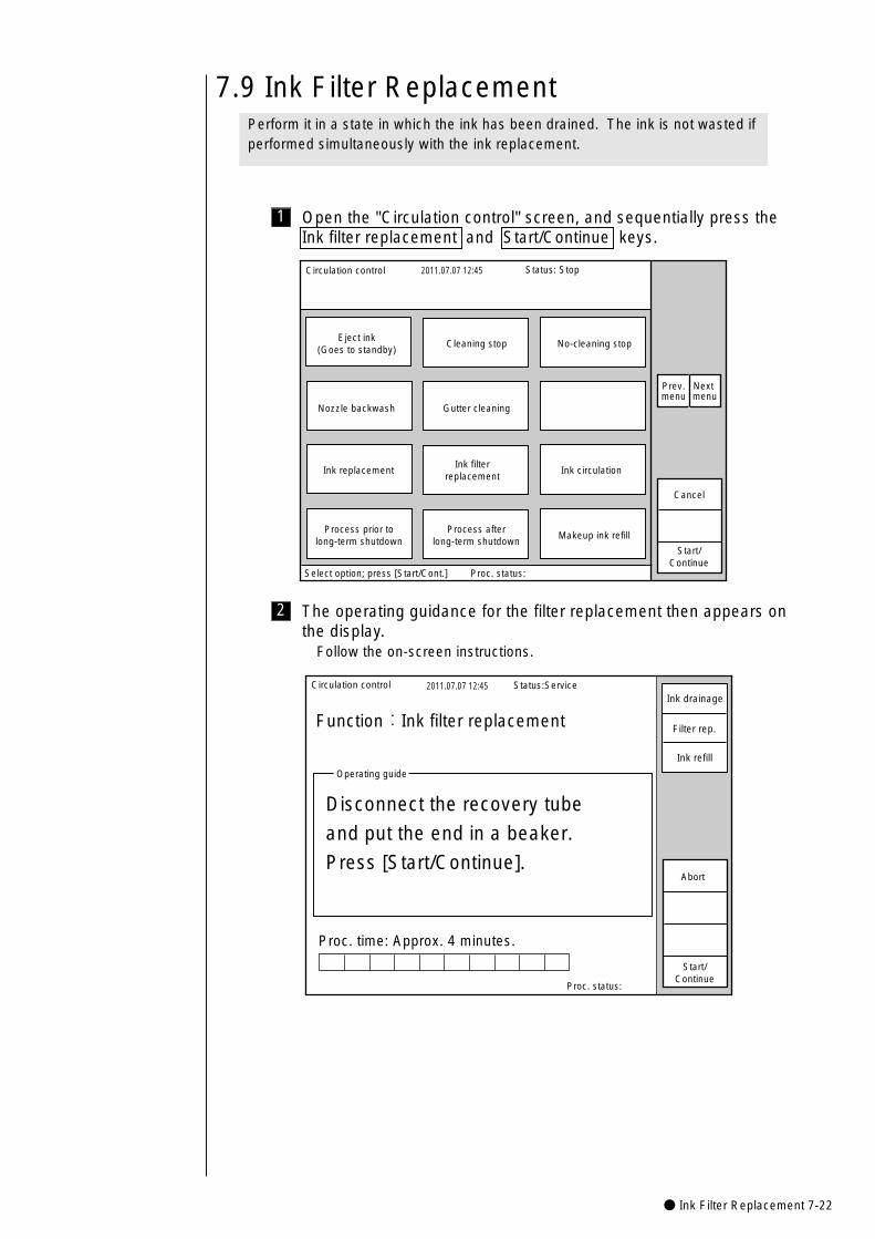
● Ink Filter Replacement 7-22
7.9 Ink Filter Replacement
1
Circulation control 2011.07.07 12:45
Cancel
Process afterlong-term shutdown
Ink replacement
Nozzle backwash
Process prior tolong-term shutdown
Ink circulation
Gutter cleaning
Makeup ink refill
Eject ink(Goes to standby)
Cleaning stop No-cleaning stop
Start/Continue
Select option; press [Start/Cont.] Proc. status:
Status: Stop
Ink filterreplacement
Prev.menu
Next menu
Open the "Circulation control" screen, and sequentially press theInk filter replacement and Start/Continue keys.
2
Circulation control 2011.07.07 12:45
Proc. status:
Function:Ink filter replacement
Proc. time: Approx. 4 minutes.
Operating guide
Disconnect the recovery tube
and put the end in a beaker.
Press [Start/Continue].
Status:Service
Start/Continue
Abort
Ink drainage
Filter rep.
Ink refill
The operating guidance for the filter replacement then appears onthe display.
Follow the on-screen instructions.
Perform it in a state in which the ink has been drained. The ink is not wasted ifperformed simultaneously with the ink replacement.
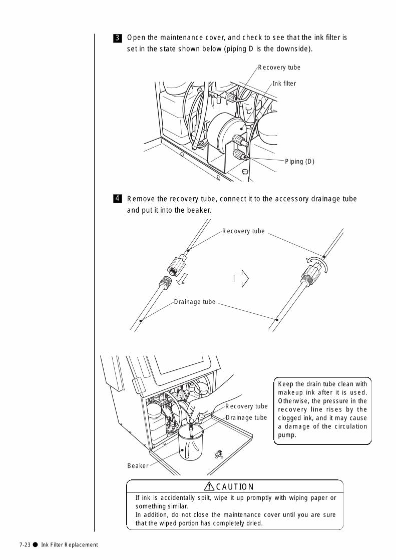
7-23● Ink Filter Replacement
4 Remove the recovery tube, connect it to the accessory drainage tube
and put it into the beaker.
3 Open the maintenance cover, and check to see that the ink filter is
set in the state shown below (piping D is the downside).
Piping (D)
Recovery tube
Ink filter
Recovery tube
Drainage tube
If ink is accidentally spilt, wipe it up promptly with wiping paper orsomething similar. In addition, do not close the maintenance cover until you are surethat the wiped portion has completely dried.
CAUTION
Keep the drain tube clean withmakeup ink after it is used.Otherwise, the pressure in therecovery l ine rises by theclogged ink, and it may causea damage of the circulationpump.
Recovery tube
Drainage tube
Beaker
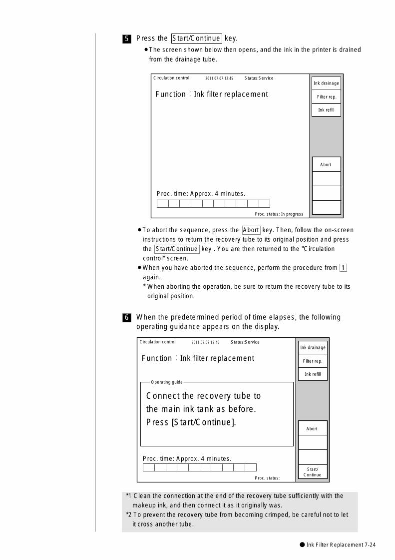
● Ink Filter Replacement 7-24
6 When the predetermined period of time elapses, the followingoperating guidance appears on the display.
¡To abort the sequence, press the Abort key. Then, follow the on-screeninstructions to return the recovery tube to its original position and pressthe Start/Continue key . You are then returned to the "Circulationcontrol" screen.
¡When you have aborted the sequence, perform the procedure from 1again.* When aborting the operation, be sure to return the recovery tube to its
original position.
5 Press the Start/Continue key.
¡The screen shown below then opens, and the ink in the printer is drained
from the drainage tube.
Circulation control 2011.07.07 12:45
Proc. status: In progress
Function:Ink filter replacement
Proc. time: Approx. 4 minutes.
Status:Service
Abort
Ink drainage
Filter rep.
Ink refill
Circulation control 2011.07.07 12:45
Proc. status:
Function:Ink filter replacement
Operating guide
Connect the recovery tube to
the main ink tank as before.
Press [Start/Continue].
Status:Service
Start/Continue
Abort
Ink drainage
Filter rep.
Ink refill
Proc. time: Approx. 4 minutes.
*1 Clean the connection at the end of the recovery tube sufficiently with themakeup ink, and then connect it as it originally was.
*2 To prevent the recovery tube from becoming crimped, be careful not to letit cross another tube.
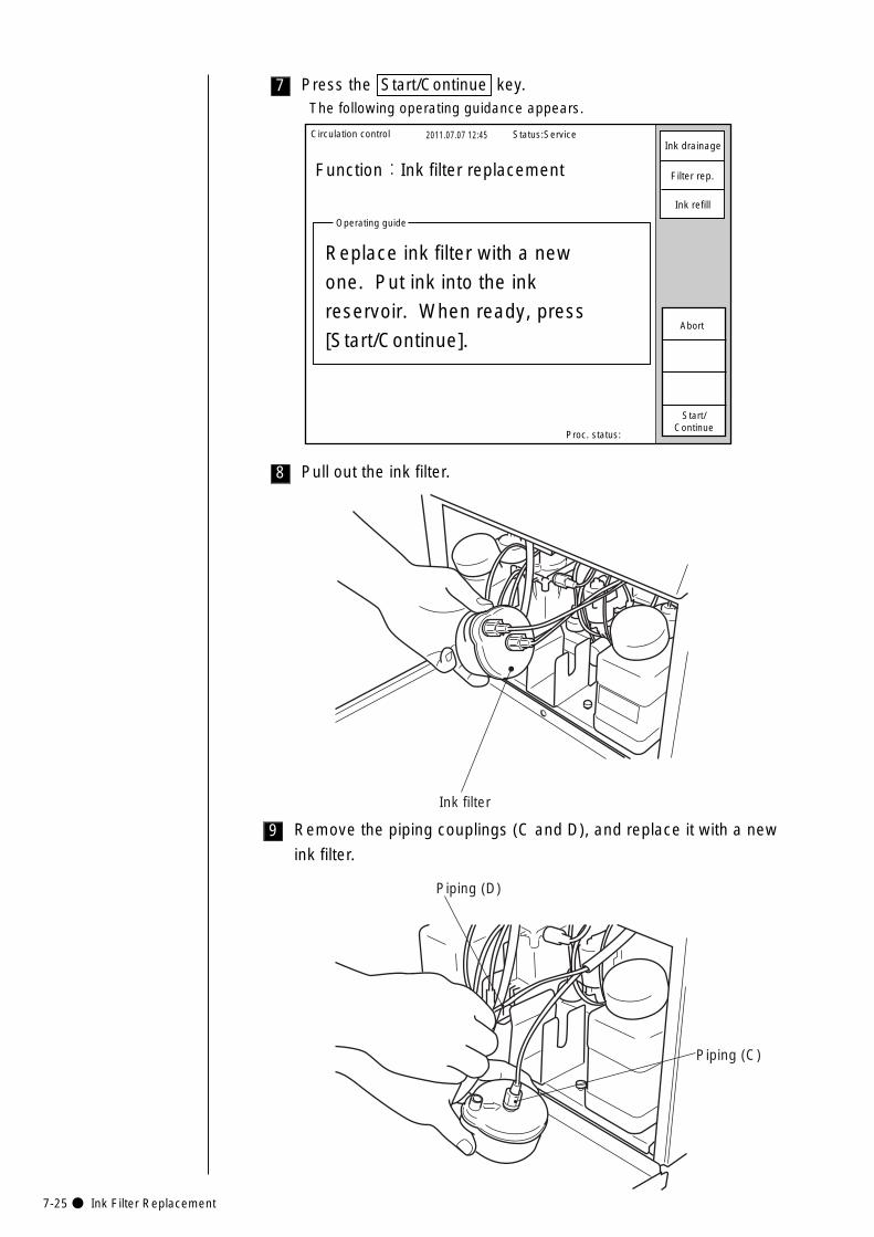
7-25● Ink Filter Replacement
Remove the piping couplings (C and D), and replace it with a new
ink filter.
9
Piping (C)
Piping (D)
Ink filter
Circulation control 2011.07.07 12:45
Proc. status:
Function:Ink filter replacement
Operating guide
Replace ink filter with a new
one. Put ink into the ink
reservoir. When ready, press
[Start/Continue].
Status:Service
Start/Continue
Abort
Ink drainage
Filter rep.
Ink refill
8 Pull out the ink filter.
7 Press the Start/Continue key.The following operating guidance appears.
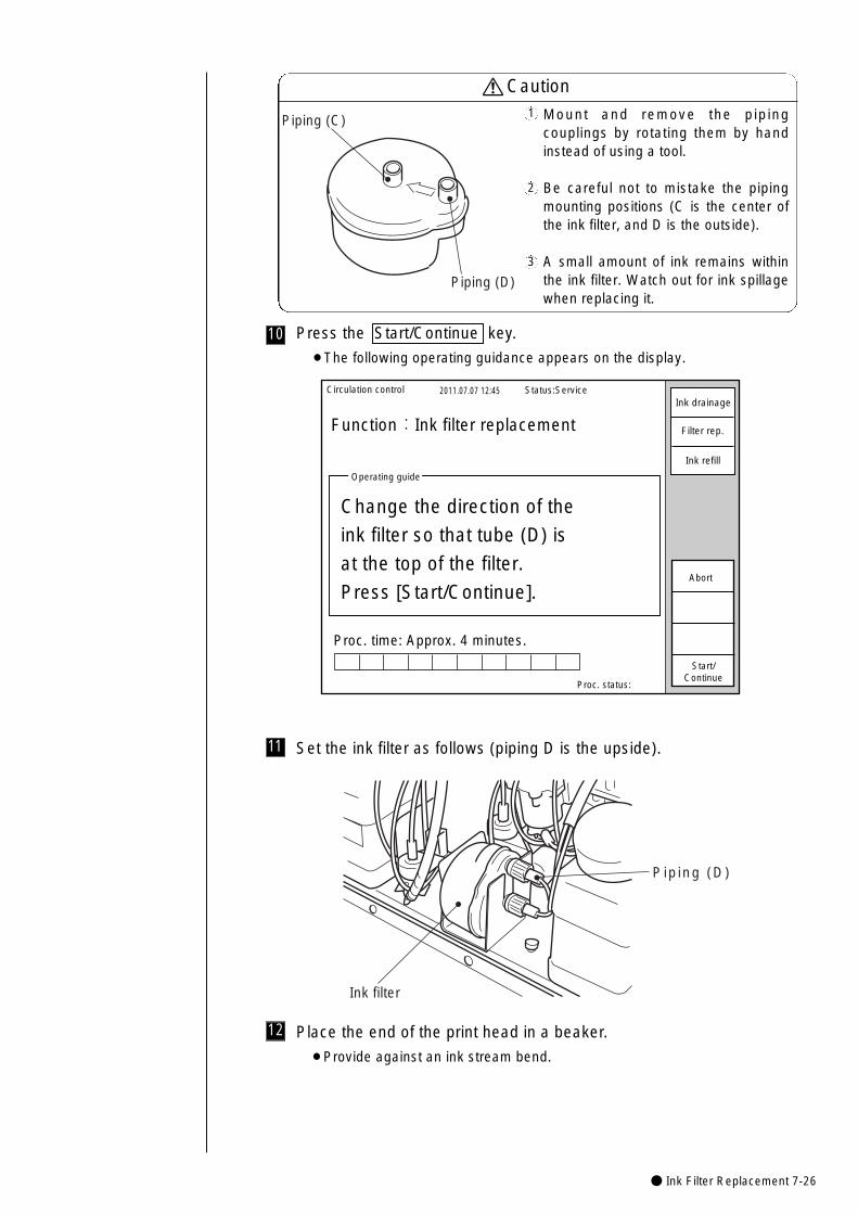
● Ink Filter Replacement 7-26
11 Set the ink filter as follows (piping D is the upside).
Piping (D)
Ink filter
Mount and remove the pipingcouplings by rotating them by handinstead of using a tool.
Be careful not to mistake the pipingmounting positions (C is the center ofthe ink filter, and D is the outside).
A small amount of ink remains withinthe ink filter. Watch out for ink spillagewhen replacing it.
Caution1
2
3
Piping (C)
Piping (D)
10 Press the Start/Continue key.
¡The following operating guidance appears on the display.
Circulation control 2011.07.07 12:45
Proc. status:
Function:Ink filter replacement
Proc. time: Approx. 4 minutes.
Operating guide
Change the direction of the
ink filter so that tube (D) is
at the top of the filter.
Press [Start/Continue].
Status:Service
Start/Continue
Abort
Ink drainage
Filter rep.
Ink refill
12 Place the end of the print head in a beaker.
¡Provide against an ink stream bend.
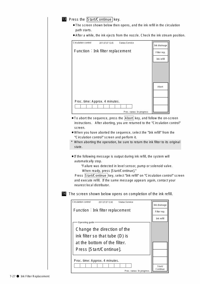
7-27● Ink Filter Replacement
14 The screen shown below opens on completion of the ink refill.
Circulation control 2011.07.07 12:45
Proc. status: In progress.
Function:Ink filter replacement
Proc. time: Approx. 4 minutes.
Operating guide
Change the direction of the
ink filter so that tube (D) is
at the bottom of the filter.
Press [Start/Continue].
Status:Service
Start/Continue
Ink drainage
Filter rep.
Ink refill
13 Press the Start/Continue key.
¡The screen shown below then opens, and the ink refill in the circulation
path starts.
¡After a while, the ink ejects from the nozzle. Check the ink stream position.
Circulation control 2011.07.07 12:45
Proc. status: In progress
Function:Ink filter replacement
Proc. time: Approx. 4 minutes.
Status:Service
Abort
Ink drainage
Filter rep.
Ink refill
¡To abort the sequence, press the Abort key, and follow the on-screeninstructions. After aborting, you are returned to the "Circulation control"screen.
¡When you have aborted the sequence, select the "Ink refill" from the"Circulation control" screen and perform it.
* When aborting the operation, be sure to return the ink filter to its originalstate.
¡If the following message is output during ink refill, the system willautomatically stop.
"Failure was detected in level sensor, pump or solenoid valve. When ready, press [Start/Continue]."
Press Start/Continue key, select "Ink refill" on "Circulation control" screenand execute refill. If the same message appears again, contact yournearest local distributor.
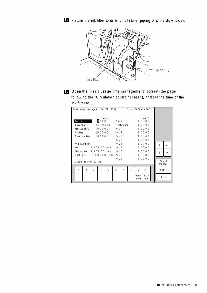
● Ink Filter Replacement 7-28
Return the ink filter to its original state (piping D is the downside).15
Open the "Parts usage time management" screen (the page
following the "Circulation control" screen), and set the time of the
ink filter to 0.
16
Piping (D)
Ink filter
1 2 3 4 5 6 7 8 9 0
Incre-ment
Decre-ment
Parts usage time mgmt.
Ink filter [00000]
Circulation f. [00000]
Makeup ink f. [00000]
Air filter [00000]
Recovery filter [00000]�
�
<Consumption>�
Ink 000000 (ml)�
Makeup ink 000000 (ml)�
Print count 000000000�
2011.07.07 12:45
Back
Cancelchanges
Reset
Status:XXXXXXXXXX
←�
→�
↑�
↓�
(hours)Pump 00000
Heating unit 00000
MV1 00000
MV2 00000
MV3 00000
MV4 00000
MV5 00000
MV6 00000
MV7 00000
MV8 00000
MV9 00000
(hours)
Update log 2011.07.07 12:45

7-29● Recovery Filter Replacement
7.10 Recovery Filter Replacement
1 Pull out the makeup ink reservoir forward and out.
Pull out.
Makeup ink reservoir
Recovery filter
2 Rotate the nut of the recovery filter and pull it forward and out.
Nut
3 Remove the O ring and filter with tweezers and mount new ones.
4 Return it to its original state, and check to see that there is no leak
of the ink in operation.* Tighten the nut securely by hand.
O ring
Filter O ring
Filter
If ink is accidentally spilt, wipeit up promptly with wipingpaper or something similar. In addition, do not close themaintenance cover until youare sure that the wiped portionhas completely dried.
CAUTION
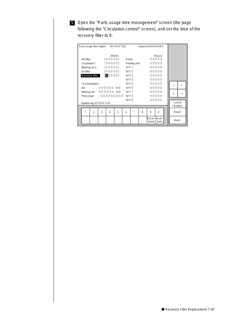
● Recovery Filter Replacement 7-30
Open the "Parts usage time management" screen (the page
following the "Circulation control" screen), and set the time of the
recovery filter to 0.
5
1 2 3 4 5 6 7 8 9 0
Incre-ment
Decre-ment
Parts usage time mgmt.
Ink filter [00000]
Circulation f. [00000]
Makeup ink f. [00000]
Air filter [00000]
Recovery filter [00000]�
�
<Consumption>�
Ink 000000 (ml)�
Makeup ink 000000 (ml)�
Print count 000000000�
2011.07.07 12:45
Back
Cancelchanges
Reset
Status:XXXXXXXXXX
←�
→�
↑�
↓�
(hours)Pump 00000
Heating unit 00000
MV1 00000
MV2 00000
MV3 00000
MV4 00000
MV5 00000
MV6 00000
MV7 00000
MV8 00000
MV9 00000
(hours)
Update log 2011.07.07 12:45
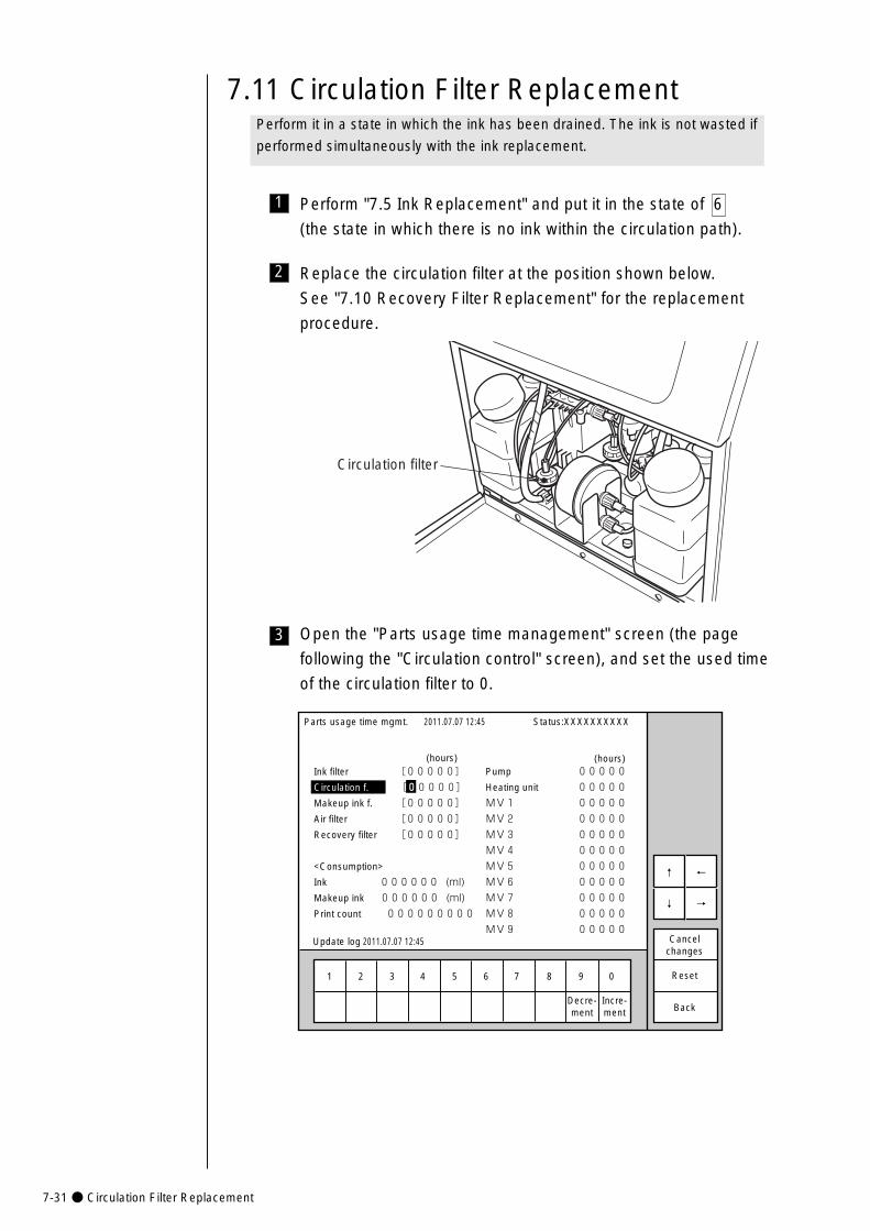
7-31● Circulation Filter Replacement
7.11 Circulation Filter ReplacementPerform it in a state in which the ink has been drained. The ink is not wasted if
performed simultaneously with the ink replacement.
1 Perform "7.5 Ink Replacement" and put it in the state of 6
(the state in which there is no ink within the circulation path).
Circulation filter
2 Replace the circulation filter at the position shown below.
See "7.10 Recovery Filter Replacement" for the replacement
procedure.
Open the "Parts usage time management" screen (the page
following the "Circulation control" screen), and set the used time
of the circulation filter to 0.
3
1 2 3 4 5 6 7 8 9 0
Incre-ment
Decre-ment
Parts usage time mgmt.
Ink filter [00000]
Circulation f. [00000]
Makeup ink f. [00000]
Air filter [00000]
Recovery filter [00000]�
�
<Consumption>�
Ink 000000 (ml)�
Makeup ink 000000 (ml)�
Print count 000000000�
2011.07.07 12:45
Back
Cancelchanges
Reset
Status:XXXXXXXXXX
←�
→�
↑�
↓�
(hours)Pump 00000
Heating unit 00000
MV1 00000
MV2 00000
MV3 00000
MV4 00000
MV5 00000
MV6 00000
MV7 00000
MV8 00000
MV9 00000
(hours)
Update log 2011.07.07 12:45
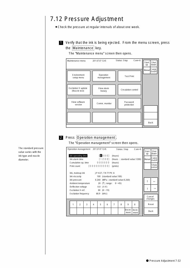
● Pressure Adjustment 7-32
2
1 Verify that the ink is being ejected. From the menu screen, press
the Maintenance key.
The "Maintenance menu" screen then opens.
1 2 3 4 5 6 7 8 9 0
Operation management
Ink operating time [0000] (hours)
Ink alarm time [1200] (hours; standard value:1200)
Cumulative op. time 000000 (hours)
Print count [000000000] (prints)
Ink, makeup ink JP-K27, TH-TYPE A
Ink viscosity 100 (standard value:100)
Ink pressure 0.260 (MPa ; standard value:0.260)
Ambient temperature 20 ( C; range: 0~45)
Deflection voltage 0.0 ( k V)
Excitation V-ref. 00 (0~19)
Excitation frequency 68.9 (kHz)
2011.07.07 12:45
Cancel changes
Reset
Incre-ment
Decre-ment
Back
Manual
Showcursor
↓
↑
→
←
Status: Stop Com=0Startup
Shutdown
CommOn/Off
7.12 Pressure Adjustment
Press Operation management .
The "Operation management" screen then opens.
¡Check the pressure at regular intervals of about one week.
The standard pressure
value varies with the
ink type and nozzle
diameter.
Maintenance menu 2011.07.07 12:45
Environmentsetup menu
Operation management
Test Print
Excitation V update(Nozzle test)
View software version
View alarmhistory Circulation control
Passwordprotection
Comm. monitor
Back
Manual
Status: Stop Com=0 Startup
Shutdown
CommOn/Off
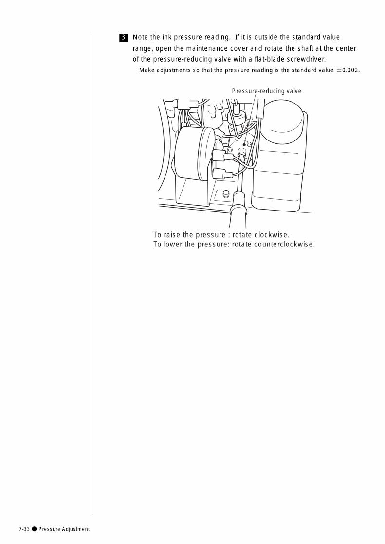
7-33● Pressure Adjustment
3
Pressure-reducing valve
To raise the pressure : rotate clockwise.To lower the pressure: rotate counterclockwise.
Note the ink pressure reading. If it is outside the standard value
range, open the maintenance cover and rotate the shaft at the center
of the pressure-reducing valve with a flat-blade screwdriver.
Make adjustments so that the pressure reading is the standard value ±0.002.
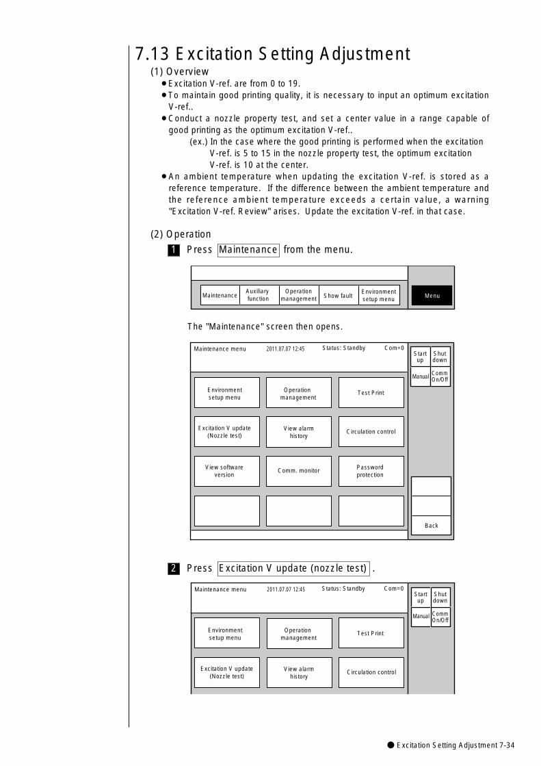
● Excitation Setting Adjustment 7-34
2
7.13 Excitation Setting Adjustment
Press Excitation V update (nozzle test) .
(1) Overview¡Excitation V-ref. are from 0 to 19.¡To maintain good printing quality, it is necessary to input an optimum excitation
V-ref..¡Conduct a nozzle property test, and set a center value in a range capable of
good printing as the optimum excitation V-ref..(ex.) In the case where the good printing is performed when the excitation
V-ref. is 5 to 15 in the nozzle property test, the optimum excitationV-ref. is 10 at the center.
¡An ambient temperature when updating the excitation V-ref. is stored as areference temperature. If the difference between the ambient temperature andthe reference ambient temperature exceeds a certain value, a warning"Excitation V-ref. Review" arises. Update the excitation V-ref. in that case.
(2) Operation
MaintenanceAuxiliary function Show fault Menu
Operationmanagement
Environmentsetup menu
The "Maintenance" screen then opens.
Maintenance menu 2011.07.07 12:45
Environmentsetup menu
Operation management
Test Print
Excitation V update(Nozzle test)
View softwareversion
View alarmhistory
Circulation control
Passwordprotection
Comm. monitor
Back
Manual
Startup
Shutdown
CommOn/Off
Status: Standby Com=0
Maintenance menu 2011.07.07 12:45
Environmentsetup menu
Operation management
Test Print
Excitation V update(Nozzle test)
View alarmhistory
Circulation control
Manual
Startup
Shutdown
CommOn/Off
Status: Standby Com=0
1 Press Maintenance from the menu.
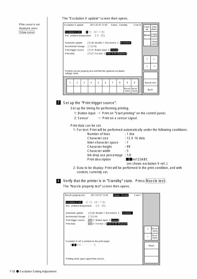
7-35● Excitation Setting Adjustment
The "Excitation V update" screen then opens.
1 2 3 4 5 6 7 8 9 0
Excitation V update 2011.07.07 12:45
Excitation V-ref. [11] (0~19)
Ref. ambient temperature 23 (℃)
Automatic update [2] (0: disable 1: Decrement 2 : Increment )
Incremental change [1] (1-9)
Print trigger source [2] (1: Button input 2: Sensor )
Print data [2] (1: For test 2: Data to be displayed)
Perform nozzle property test and find the optimum excitationvoltage value.
Back
←�
→�
↑�
↓�
Nozzle test
Decre-ment
Incre-ment
Status : Standby Com=0
Manual
Startup
Shutdown
CommOn/Off
Showcursor
If the cursor is not
displayed, press
Show cursor .
3 Set up the "Print trigger source".Set up the timing for performing printing.
1: Button input → Print on "Start printing" on the control panel.
2: Sensor → Print on a sensor signal.
4 Verify that the printer is in "Standby" state. Press Nozzle test .The "Nozzle property test" screen then opens.
Nozzle property test 2011.07.07 12:45
Excitation V-ref. [11] (0~19)
Ref. ambient tempereture 23 (℃)
Automatic update [2] (0: disable 1: Decrement 2 : Increment )
Incremental change [1] (1-9)
Print trigger source [2] (1: Button input 2: Sensor )
Print data [2] (1: For test 2: Data to be displayed)
Excitation V-ref. is printed on the print target.
[ nn・・・・・・]
Printing starts upon signal from sensor.
↑�
↓�
Abort
Decre-ment
Incre-ment
Status : Ready Com=1
Print data can be set.1: For test: Print will be performed automatically under the following conditions:
Number of lines : 1 lineCharacter size : 12 X 16 dotsInter-character space : 1Character height : 99Character width : 5Ink drop use percentage : 1/3Print description :■■nn123ABC
(nn shows excitation V-ref..)2: Data to be display: Print will be performed in the print condition, and with
content, currently set.
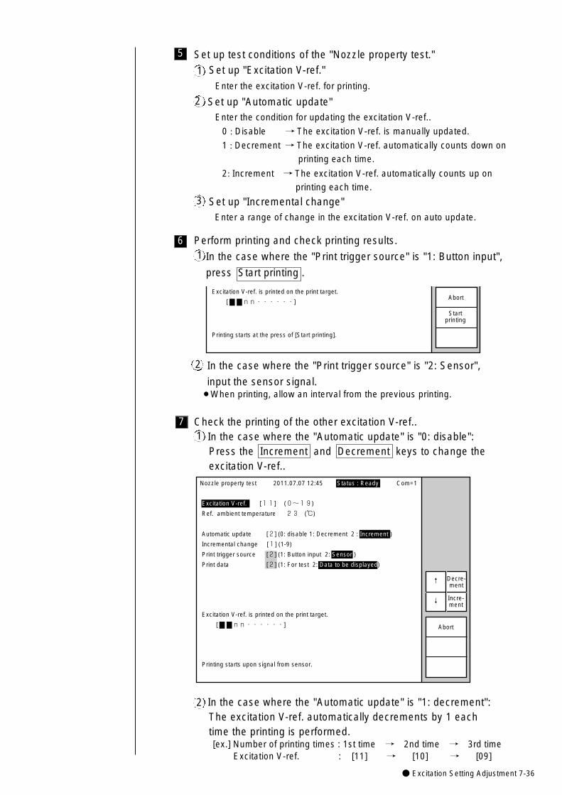
● Excitation Setting Adjustment 7-36
In the case where the "Automatic update" is "1: decrement":The excitation V-ref. automatically decrements by 1 each time the printing is performed.[ex.] Number of printing times : 1st time → 2nd time → 3rd time
Excitation V-ref. : [11] → [10] → [09]
2
Check the printing of the other excitation V-ref.. In the case where the "Automatic update" is "0: disable":Press the Increment and Decrement keys to change the excitation V-ref..
17
5 Set up test conditions of the "Nozzle property test."
Set up "Excitation V-ref."
Enter the excitation V-ref. for printing.
Set up "Automatic update"Enter the condition for updating the excitation V-ref..
0 : Disable → The excitation V-ref. is manually updated.
1 : Decrement → The excitation V-ref. automatically counts down on
printing each time.
2: Increment → The excitation V-ref. automatically counts up on
printing each time.
Set up "Incremental change"Enter a range of change in the excitation V-ref. on auto update.
1
2
3
6 Perform printing and check printing results.
In the case where the "Print trigger source" is "1: Button input",
press Start printing .
Excitation V-ref. is printed on the print target.
[ nn・・・・・・]
Printing starts at the press of [Start printing].
Abort
Startprinting
1
In the case where the "Print trigger source" is "2: Sensor",
input the sensor signal.¡When printing, allow an interval from the previous printing.
2
Nozzle property test 2011.07.07 12:45
Excitation V-ref. [11] (0~19)
Ref. ambient temperature 23 (℃)
Automatic update [2] (0: disable 1: Decrement 2 : Increment )
Incremental change [1] (1-9)
Print trigger source [2] (1: Button input 2: Sensor )
Print data [2] (1: For test 2: Data to be displayed)
Excitation V-ref. is printed on the print target.
[ nn・・・・・・]
Printing starts upon signal from sensor.
↑�
↓�
Abort
Decre-ment
Incre-ment
Status : Ready Com=1
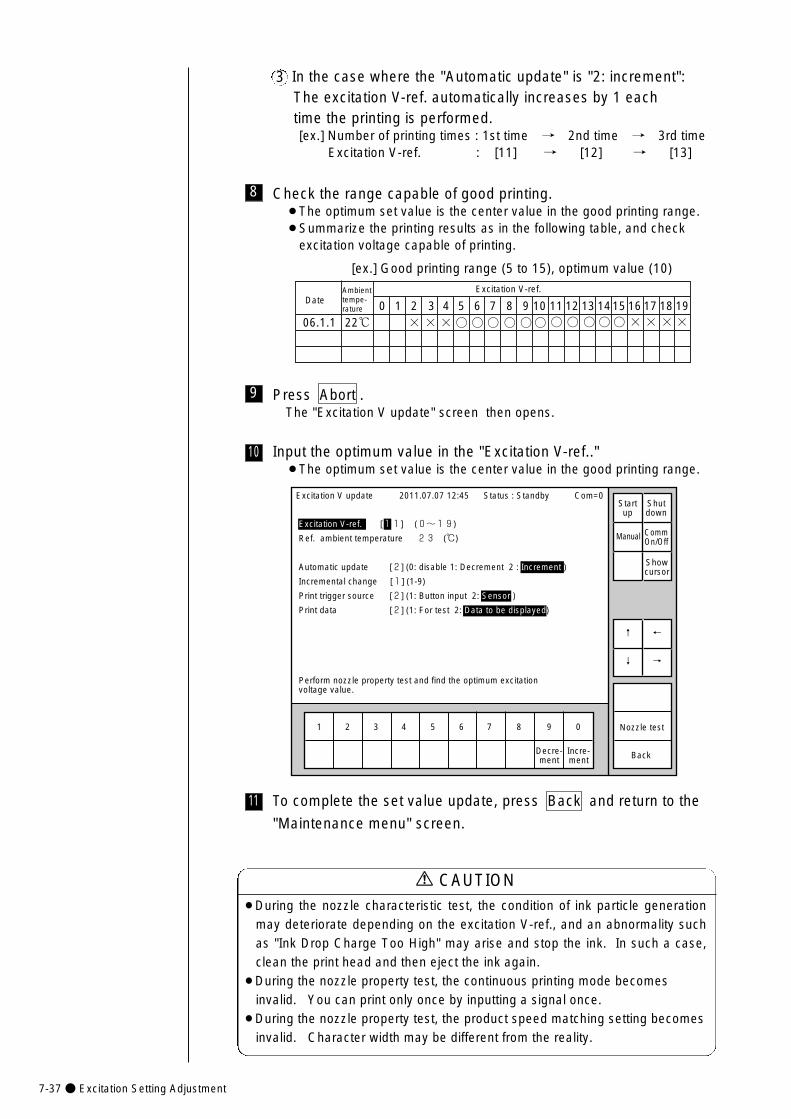
7-37● Excitation Setting Adjustment
¡During the nozzle characteristic test, the condition of ink particle generationmay deteriorate depending on the excitation V-ref., and an abnormality suchas "Ink Drop Charge Too High" may arise and stop the ink. In such a case,clean the print head and then eject the ink again.
¡During the nozzle property test, the continuous printing mode becomesinvalid. You can print only once by inputting a signal once.
¡During the nozzle property test, the product speed matching setting becomesinvalid. Character width may be different from the reality.
CAUTION
In the case where the "Automatic update" is "2: increment":The excitation V-ref. automatically increases by 1 each time the printing is performed.[ex.] Number of printing times : 1st time → 2nd time → 3rd time
Excitation V-ref. : [11] → [12] → [13]
3
8 Check the range capable of good printing.¡The optimum set value is the center value in the good printing range. ¡Summarize the printing results as in the following table, and check
excitation voltage capable of printing.
Excitation V-ref.
[ex.] Good printing range (5 to 15), optimum value (10)
DateAmbient tempe-rature
22℃06.1.10 1 2 3 4 5 6 7 8 9 10 11 12 13 1415 16 17 18 19
× × ×○ ○ ○ ○ ○○ ○ ○ ○○○ × × ××
10
11
Input the optimum value in the "Excitation V-ref.."¡The optimum set value is the center value in the good printing range.
To complete the set value update, press Back and return to the
"Maintenance menu" screen.
9 Press Abort .The "Excitation V update" screen then opens.
1 2 3 4 5 6 7 8 9 0
Excitation V update 2011.07.07 12:45
Excitation V-ref. [11] (0~19)
Ref. ambient temperature 23 (℃)
Automatic update [2] (0: disable 1: Decrement 2 : Increment )
Incremental change [1] (1-9)
Print trigger source [2] (1: Button input 2: Sensor )
Print data [2] (1: For test 2: Data to be displayed)
Perform nozzle property test and find the optimum excitationvoltage value.
Back
←�
→�
↑�
↓�
Nozzle test
Decre-ment
Incre-ment
Status : Standby Com=0
Manual
Startup
Shutdown
CommOn/Off
Showcursor
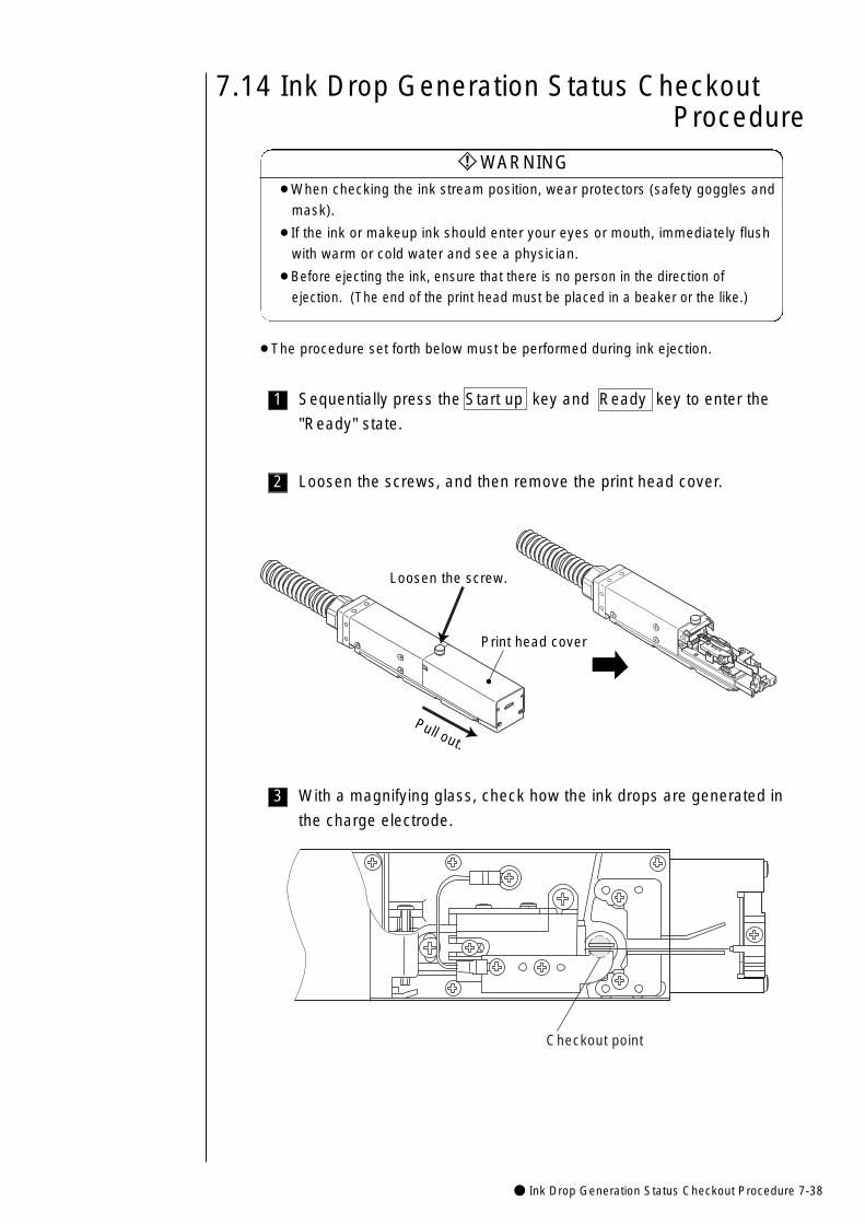
● Ink Drop Generation Status Checkout Procedure 7-38
7.14 Ink Drop Generation Status Checkout Procedure
¡When checking the ink stream position, wear protectors (safety goggles and
mask).
¡If the ink or makeup ink should enter your eyes or mouth, immediately flush
with warm or cold water and see a physician.
¡Before ejecting the ink, ensure that there is no person in the direction of
ejection. (The end of the print head must be placed in a beaker or the like.)
WARNING
¡The procedure set forth below must be performed during ink ejection.
1 Sequentially press the Start up key and Ready key to enter the
"Ready" state.
2 Loosen the screws, and then remove the print head cover.
3 With a magnifying glass, check how the ink drops are generated in
the charge electrode.
Checkout point
Pull out.
Loosen the screw.
Print head cover
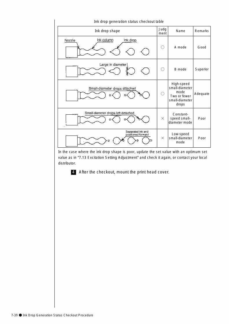
7-39● Ink Drop Generation Status Checkout Procedure
Ink drop shape Judgment
Name Remarks
○
○
○
×
×
A mode
B mode
High-speedsmall-diameter
modeTwo or fewer
small-diameterdrops
Constant-speed small-
diameter mode
Low-speedsmall-diameter
mode
Good
Superior
Adequate
Poor
Poor
4 After the checkout, mount the print head cover.
Ink drop generation status checkout table
In the case where the ink drop shape is poor, update the set value with an optimum set
value as in "7.13 Excitation Setting Adjustment" and check it again, or contact your local
distributor.
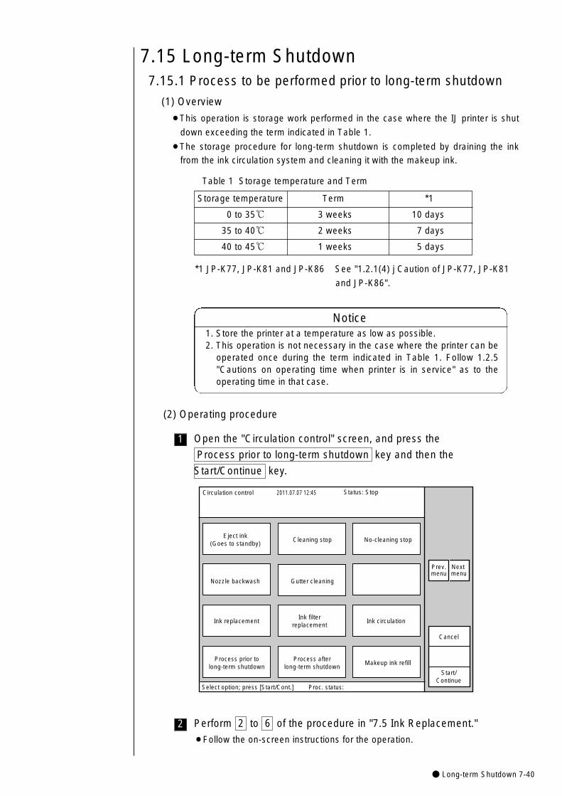
● Long-term Shutdown 7-40
7.15 Long-term Shutdown7.15.1 Process to be performed prior to long-term shutdown
(1) Overview
¡This operation is storage work performed in the case where the IJ printer is shut
down exceeding the term indicated in Table 1.
¡The storage procedure for long-term shutdown is completed by draining the ink
from the ink circulation system and cleaning it with the makeup ink.
1 Open the "Circulation control" screen, and press the
Process prior to long-term shutdown key and then the
Start/Continue key.
1. Store the printer at a temperature as low as possible.2. This operation is not necessary in the case where the printer can be
operated once during the term indicated in Table 1. Follow 1.2.5"Cautions on operating time when printer is in service" as to theoperating time in that case.
Notice
(2) Operating procedure
Table 1 Storage temperature and Term
Storage temperature Term *1
0 to 35℃ 3 weeks 10 days
35 to 40℃ 2 weeks 7 days
40 to 45℃ 1 weeks 5 days
Circulation control 2011.07.07 12:45
Cancel
Process afterlong-term shutdown
Ink replacement
Nozzle backwash
Process prior tolong-term shutdown
Ink circulation
Gutter cleaning
Makeup ink refill
Eject ink(Goes to standby)
Cleaning stop No-cleaning stop
Start/Continue
Select option; press [Start/Cont.] Proc. status:
Status: Stop
Ink filterreplacement
Prev.menu
Next menu
2 Perform 2 to 6 of the procedure in "7.5 Ink Replacement."
¡Follow the on-screen instructions for the operation.
*1 JP-K77, JP-K81 and JP-K86 See "1.2.1(4) j Caution of JP-K77, JP-K81
and JP-K86".
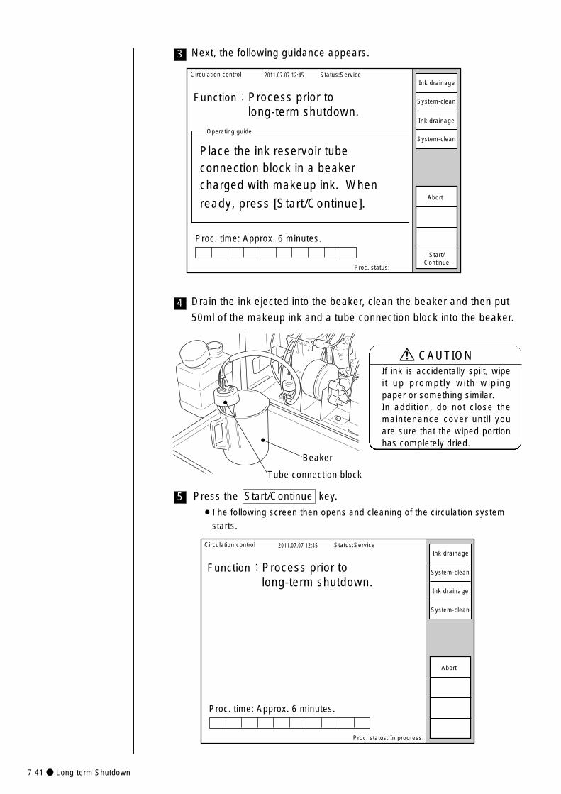
7-41● Long-term Shutdown
Circulation control 2011.07.07 12:45
Proc. status:
Function:Process prior to long-term shutdown.
Proc. time: Approx. 6 minutes.
Operating guide
Place the ink reservoir tubeconnection block in a beakercharged with makeup ink. When�
ready, press [Start/Continue].
Status:Service
Start/Continue
Abort
Ink drainage
System-clean
Ink drainage
System-clean
5 Press the Start/Continue key.
¡The following screen then opens and cleaning of the circulation system
starts.
Circulation control 2011.07.07 12:45
Proc. status: In progress.
Function:Process prior to long-term shutdown.
Proc. time: Approx. 6 minutes.
Status:Service
Abort
Ink drainage
Ink drainage
System-clean
System-clean
Next, the following guidance appears.3
Drain the ink ejected into the beaker, clean the beaker and then put
50ml of the makeup ink and a tube connection block into the beaker.4
Beaker
Tube connection block
If ink is accidentally spilt, wipeit up promptly with wipingpaper or something similar. In addition, do not close themaintenance cover until youare sure that the wiped portionhas completely dried.
CAUTION
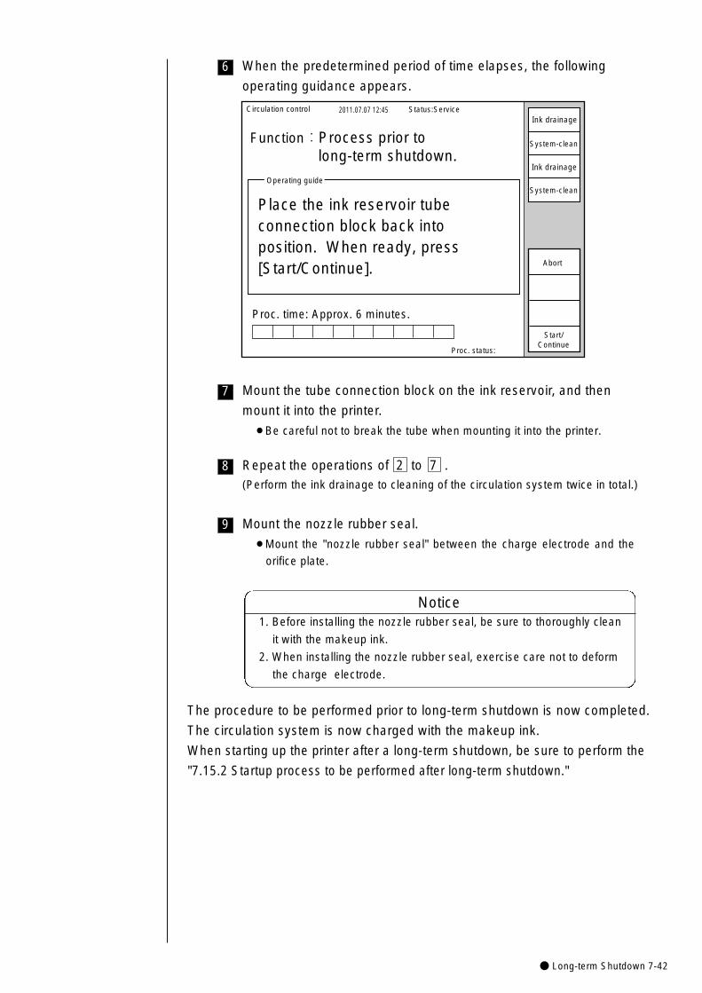
● Long-term Shutdown 7-42
6 When the predetermined period of time elapses, the following
operating guidance appears.
Circulation control 2011.07.07 12:45
Proc. status:
Function:Process prior to long-term shutdown.
Proc. time: Approx. 6 minutes.
Operating guide
Place the ink reservoir tubeconnection block back into position. When ready, press�[Start/Continue].
Status:Service
Start/Continue
Abort
Ink drainage
Ink drainage
System-clean
System-clean
7 Mount the tube connection block on the ink reservoir, and then
mount it into the printer.
¡Be careful not to break the tube when mounting it into the printer.
8 Repeat the operations of 2 to 7 .(Perform the ink drainage to cleaning of the circulation system twice in total.)
9 Mount the nozzle rubber seal.
¡Mount the "nozzle rubber seal" between the charge electrode and the
orifice plate.
1. Before installing the nozzle rubber seal, be sure to thoroughly clean
it with the makeup ink.
2. When installing the nozzle rubber seal, exercise care not to deform
the charge electrode.
Notice
The procedure to be performed prior to long-term shutdown is now completed.
The circulation system is now charged with the makeup ink.
When starting up the printer after a long-term shutdown, be sure to perform the
"7.15.2 Startup process to be performed after long-term shutdown."

7-43● Long-term Shutdown
7.15.2 Startup process to be performed after long-term shutdown(1) Overview
¡This operation is the work for draining the makeup ink which cleaned the inkcirculation system at the long-term shutdown of the IJ printer and refilling it withthe ink.
¡To completely drain the makeup ink from the circulation system, you shouldcharge the circulation system with the ink, drain the ink, and fill the ink againinto the system.
(2) Operating procedure
2 Press the Ink stream alignment key and then the Start/Continue
key.
1 Remove the nozzle rubber seal.
3 Open the "Circulation control" screen, and press the
Process after long-term shutdown key and then the Start/Continue
key.
1. ck to see that the makeup ink is ejecting from the nozzle.
If not ejecting, repair it according to "Table 1. Repairing the printer
after the long-term shutdown."
2. If it is ejecting, check the stream position. See "7.7 Adjusting the Ink
Stream Position" for the method.
Notice
Circulation control 2011.07.07 12:45
Cancel
Process afterlong-term shutdown
Ink replacement
Nozzle backwash
Process prior tolong-term shutdown
Ink circulation
Gutter cleaning
Makeup ink refill
Eject ink(Goes to standby)
Cleaning stop No-cleaning stop
Start/Continue
Select option; press [Start/Cont.] Proc. status:
Status: Stop
Ink filterreplacement
Prev.menu
Next menu
4 Follow the on-screen instructions for the operation.
¡Repeat the same procedure as in "7.5 Ink Replacement" twice.
In the case where you cannot perform the drainage or refill of the ink,
repair it according to "Table 1. Repairing the printer after the long-
term shutdown."
Notice
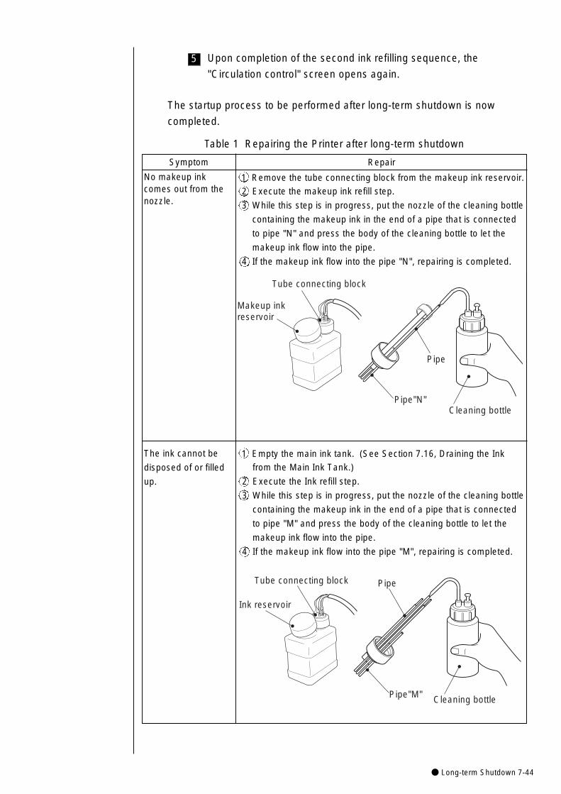
● Long-term Shutdown 7-44
5 Upon completion of the second ink refilling sequence, the
"Circulation control" screen opens again.
The startup process to be performed after long-term shutdown is now
completed.
Table 1 Repairing the Printer after long-term shutdown
No makeup inkcomes out from thenozzle.
RepairSymptom
1 Remove the tube connecting block from the makeup ink reservoir.
2 Execute the makeup ink refill step.
3 While this step is in progress, put the nozzle of the cleaning bottle
containing the makeup ink in the end of a pipe that is connected
to pipe "N" and press the body of the cleaning bottle to let the
makeup ink flow into the pipe.
4 If the makeup ink flow into the pipe "N", repairing is completed.
Makeup ink reservoir
Tube connecting block
Cleaning bottle
Pipe
Pipe"N"
The ink cannot be
disposed of or filled
up.
1 Empty the main ink tank. (See Section 7.16, Draining the Ink
from the Main Ink Tank.)
2 Execute the Ink refill step.
3 While this step is in progress, put the nozzle of the cleaning bottle
containing the makeup ink in the end of a pipe that is connected
to pipe "M" and press the body of the cleaning bottle to let the
makeup ink flow into the pipe.
4 If the makeup ink flow into the pipe "M", repairing is completed.
Cleaning bottle
Pipe
Pipe"M"
Ink reservoir
Tube connecting block
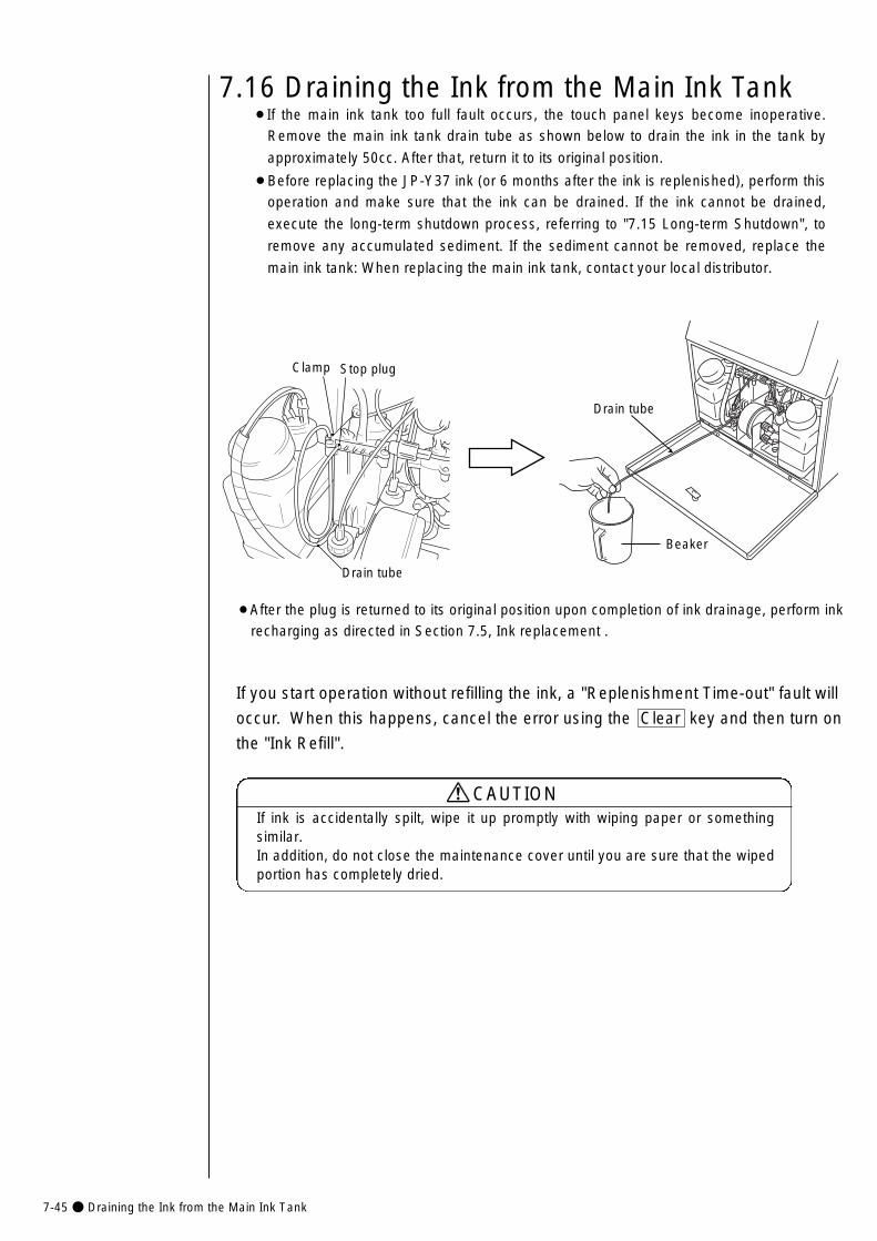
7-45● Draining the Ink from the Main Ink Tank
7.16 Draining the Ink from the Main Ink Tank¡If the main ink tank too full fault occurs, the touch panel keys become inoperative.
Remove the main ink tank drain tube as shown below to drain the ink in the tank by
approximately 50cc. After that, return it to its original position.
¡Before replacing the JP-Y37 ink (or 6 months after the ink is replenished), perform this
operation and make sure that the ink can be drained. If the ink cannot be drained,
execute the long-term shutdown process, referring to "7.15 Long-term Shutdown", to
remove any accumulated sediment. If the sediment cannot be removed, replace the
main ink tank: When replacing the main ink tank, contact your local distributor.
Drain tube
Beaker
Drain tube
Clamp Stop plug
¡After the plug is returned to its original position upon completion of ink drainage, perform ink
recharging as directed in Section 7.5, Ink replacement .
If you start operation without refilling the ink, a "Replenishment Time-out" fault will
occur. When this happens, cancel the error using the Clear key and then turn on
the "Ink Refill".
If ink is accidentally spilt, wipe it up promptly with wiping paper or somethingsimilar. In addition, do not close the maintenance cover until you are sure that the wipedportion has completely dried.
CAUTION
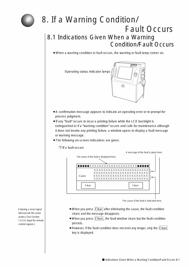
8. If a Warning Condition/Fault Occurs
● Indications Given When a Warning Condition/Fault Occurs 8-1
¡When a warning condition or fault occurs, the warning or fault lamp comes on.
¡A confirmation message appears to indicate an operating error or to prompt for
process judgment.
¡If any "fault" occurs to incur a printing failure while the LCD backlight is
extinguished or if a "warning condition" occurs and calls for maintenance although
it does not invoke any printing failure, a window opens to display a fault message
or warning message.
¡The following on-screen indications are given.
Operating status indicator lamps
PX Ink Jet Printer
If a fault occurs1
◆◆◆◆◆XXXXXXXXXXXXXXXXXXXX◆◆◆◆◆
XXXXXXXXXXXXXXXXXXXXXXX XXXXXXXXXXXXXXXXXXXXXXXCause XXXXXXXXXXXXXXXXXXXXXXX� XXXXXXXXXXXXXXXXXXXXXXX
Close
The name of the fault is displayed here.
A message of the fault is given here.
The cause of the fault is indicated here.
Clear
¡When you press Clear after eliminating the cause, the fault condition
clears and the message disappears.
¡When you press Close , the fault window clears but the fault condition
persists.
¡However, if the fault condition does not exist any longer, only the Close
key is displayed.
Entering a reset signal
will execute the same
action.( See Section
1.5.3-9, Input for remote
control signals.)
8.1 Indications Given When a Warning Condition/Fault Occurs
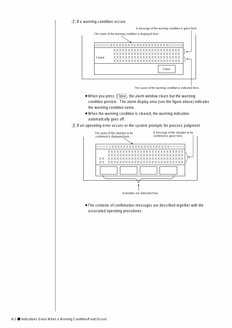
8-2● Indications Given When a Warning Condition/Fault Occurs
If a warning condition occurs2
◇◇◇◇◇XXXXXXXXXXXXXXXXXXXX◇◇◇◇◇
The name of the warning condition is displayed here.
A message of the warning condition is given here.
The cause of the warning condition is indicated here.
XXXXXXXXXXXXXXXXXXXXXXX XXXXXXXXXXXXXXXXXXXXXXXCause XXXXXXXXXXXXXXXXXXXXXXX XXXXXXXXXXXXXXXXXXXXXXX
Close
¡When you press Close , the alarm window clears but the warning
condition persists. The alarm display area (see the figure above) indicates
the warning condition name.
¡When the warning condition is cleared, the warning indication
automatically goes off.
If an operating error occurs or the system prompts for process judgment3
=====XXXXXXXXXXXXXXXXXXXX=====
XXXXXXXXXXXXXXXXXXXXXXXXXX XXXXXXXXXXXXXXXXXXXXXXXXXXXX XXXXXXXXXXXXXXXXXXXXXXXXXXXX XXXXXXXXXXXXXXXXXXXXXXXXXX
The name of the situation to be confirmed is displayed here.
A message of the situation to be confirmed is given here.
Remedies are indicated here.
¡The contents of confirmation messages are described together with the
associated operating procedures.
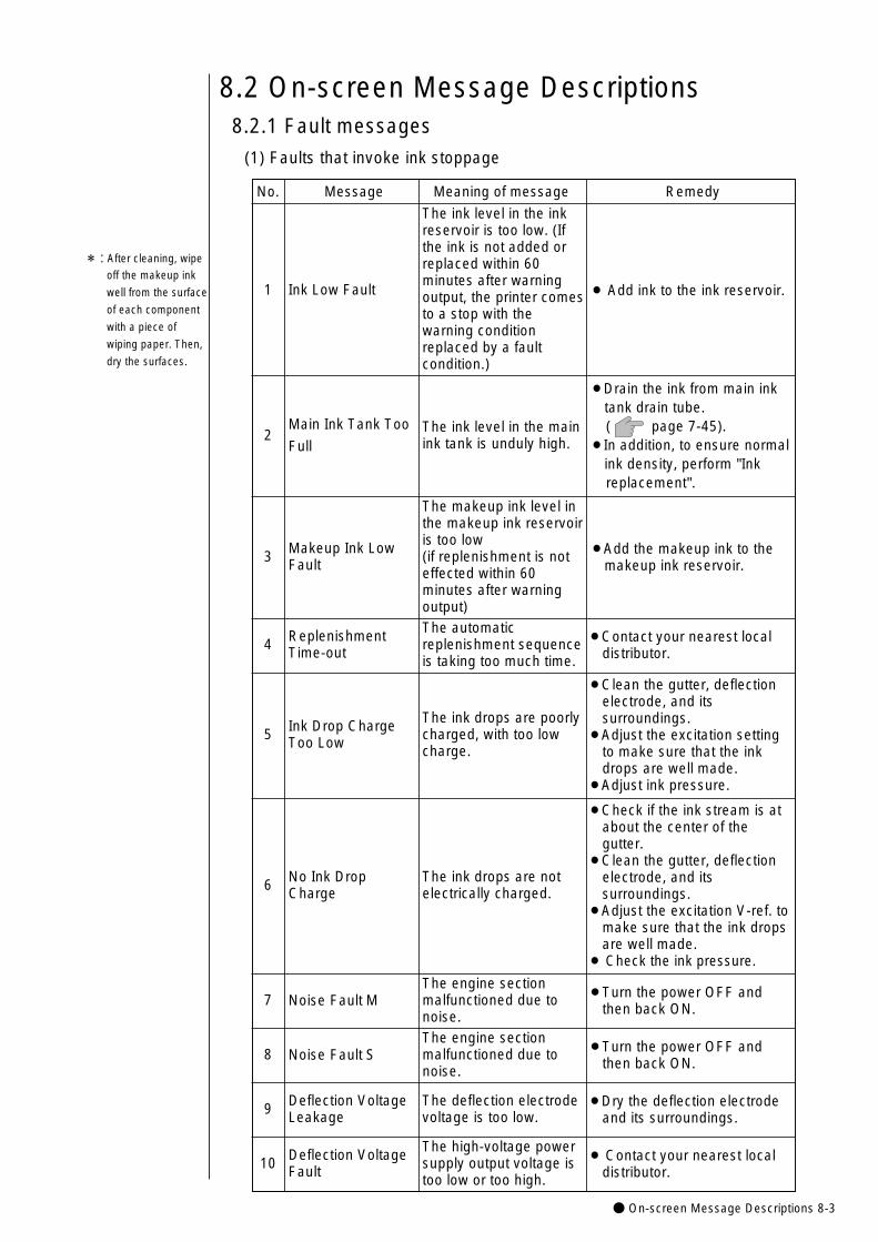
● On-screen Message Descriptions 8-3
The high-voltage powersupply output voltage istoo low or too high.
10 ¡ Contact your nearest localdistributor.
Deflection VoltageFault
5The ink drops are poorlycharged, with too lowcharge.
¡Clean the gutter, deflectionelectrode, and itssurroundings.
¡Adjust the excitation settingto make sure that the inkdrops are well made.
¡Adjust ink pressure.
Ink Drop ChargeToo Low
6
7The engine sectionmalfunctioned due tonoise.
¡Turn the power OFF andthen back ON.
Noise Fault M
8The engine sectionmalfunctioned due tonoise.
¡Turn the power OFF andthen back ON.
Noise Fault S
9 The deflection electrodevoltage is too low.
¡Dry the deflection electrodeand its surroundings.
Deflection VoltageLeakage
4The automaticreplenishment sequenceis taking too much time.
¡Contact your nearest localdistributor.
ReplenishmentTime-out
3
The makeup ink level inthe makeup ink reservoiris too low(if replenishment is noteffected within 60minutes after warningoutput)
¡Add the makeup ink to themakeup ink reservoir.
Makeup Ink LowFault
The ink drops are notelectrically charged.
¡Check if the ink stream is atabout the center of thegutter.
¡Clean the gutter, deflectionelectrode, and itssurroundings.
¡Adjust the excitation V-ref. tomake sure that the ink dropsare well made.
¡ Check the ink pressure.
No Ink DropCharge
*:After cleaning, wipe
off the makeup ink
well from the surface
of each component
with a piece of
wiping paper. Then,
dry the surfaces.
No. Message
The ink level in the inkreservoir is too low. (Ifthe ink is not added orreplaced within 60minutes after warningoutput, the printer comesto a stop with thewarning conditionreplaced by a faultcondition.)
1
2
¡ Add ink to the ink reservoir.Ink Low Fault
(1) Faults that invoke ink stoppage
8.2 On-screen Message Descriptions8.2.1 Fault messages
Meaning of message Remedy
The ink level in the mainink tank is unduly high.
¡Drain the ink from main inktank drain tube.( page 7-45).
¡In addition, to ensure normalink density, perform "Ink replacement".
Main Ink Tank Too
Full
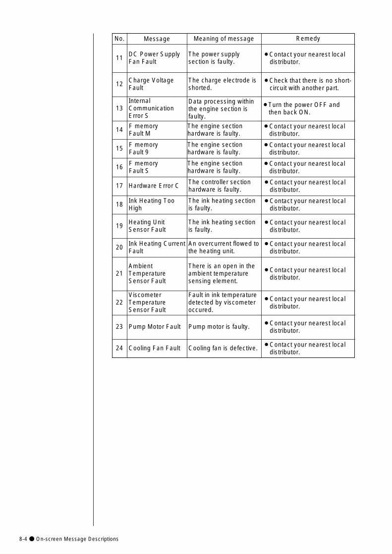
8-4● On-screen Message Descriptions
24
23
22
21
20
19
18
16
14
13
12
11
17
Ink Heating CurrentFault
An overcurrent flowed tothe heating unit.
¡Contact your nearest localdistributor.
No. Message Meaning of message Remedy
The controller sectionhardware is faulty.Hardware Error C ¡Contact your nearest local
distributor.
AmbientTemperatureSensor Fault
Cooling Fan Fault
There is an open in theambient temperaturesensing element.
Cooling fan is defective.
¡Contact your nearest localdistributor.
ViscometerTemperatureSensor Fault
Fault in ink temperaturedetected by viscometeroccured.
¡Contact your nearest localdistributor.
Pump Motor Fault Pump motor is faulty. ¡Contact your nearest localdistributor.
¡Contact your nearest localdistributor.
F memory Fault M
The engine sectionhardware is faulty.
¡Contact your nearest localdistributor.
15 F memory Fault 9
The engine sectionhardware is faulty.
¡Contact your nearest localdistributor.
F memory Fault S
The engine sectionhardware is faulty.
¡Contact your nearest localdistributor.
The ink heating sectionis faulty.
¡Contact your nearest localdistributor.
Ink Heating TooHigh
The power supplysection is faulty.
¡Contact your nearest localdistributor.
DC Power SupplyFan Fault
The charge electrode isshorted.
¡Check that there is no short-circuit with another part.
Charge VoltageFault
The ink heating sectionis faulty.
¡Contact your nearest localdistributor.
Heating UnitSensor Fault
Data processing withinthe engine section isfaulty.
InternalCommunicationError S
¡Turn the power OFF andthen back ON.
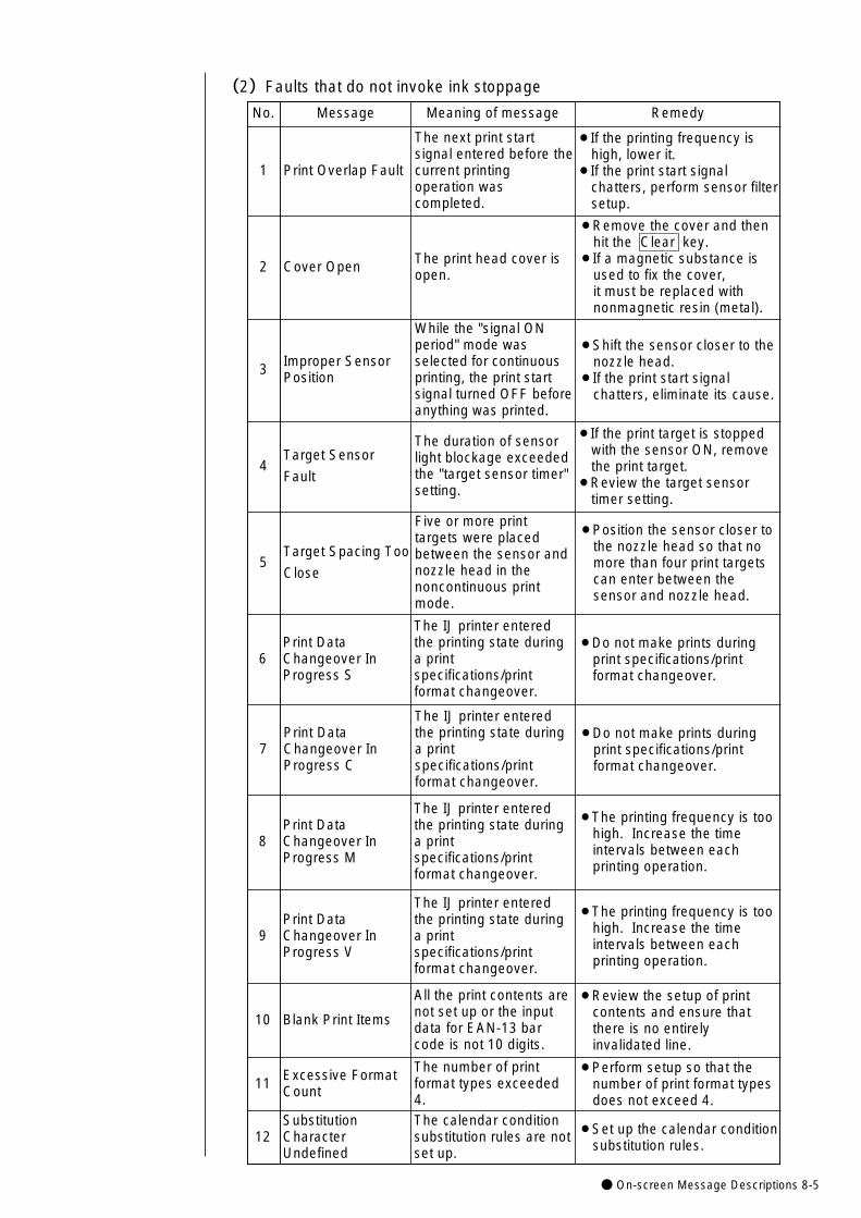
● On-screen Message Descriptions 8-5
12
Print DataChangeover InProgress C
8
The IJ printer enteredthe printing state duringa printspecifications/printformat changeover.
Print DataChangeover InProgress M
9Print DataChangeover InProgress V
The IJ printer enteredthe printing state duringa printspecifications/printformat changeover.
¡The printing frequency is toohigh. Increase the timeintervals between eachprinting operation.
The calendar conditionsubstitution rules are notset up.
SubstitutionCharacterUndefined
¡Set up the calendar conditionsubstitution rules.
10
All the print contents arenot set up or the inputdata for EAN-13 barcode is not 10 digits.
Blank Print Items
¡Review the setup of printcontents and ensure thatthere is no entirelyinvalidated line.
11The number of printformat types exceeded4.
Excessive FormatCount
¡Perform setup so that thenumber of print format typesdoes not exceed 4.
¡The printing frequency is toohigh. Increase the timeintervals between eachprinting operation.
(2)Faults that do not invoke ink stoppage
No. Message
The next print startsignal entered before thecurrent printingoperation wascompleted.
1
2
¡If the printing frequency ishigh, lower it.
¡If the print start signalchatters, perform sensor filtersetup.
Print Overlap Fault
Meaning of message Remedy
The print head cover isopen.
¡Remove the cover and thenhit the Clear key.
¡If a magnetic substance isused to fix the cover, it must be replaced withnonmagnetic resin (metal).
Cover Open
3
While the "signal ONperiod" mode wasselected for continuousprinting, the print startsignal turned OFF beforeanything was printed.
¡Shift the sensor closer to thenozzle head.
¡If the print start signalchatters, eliminate its cause.
Improper SensorPosition
4
The duration of sensorlight blockage exceededthe "target sensor timer"setting.
¡If the print target is stoppedwith the sensor ON, removethe print target.
¡Review the target sensortimer setting.
Target Sensor
Fault
5
Five or more printtargets were placedbetween the sensor andnozzle head in thenoncontinuous printmode.
¡Position the sensor closer tothe nozzle head so that nomore than four print targetscan enter between thesensor and nozzle head.
Target Spacing Too
Close
6
The IJ printer enteredthe printing state duringa printspecifications/printformat changeover.
¡Do not make prints duringprint specifications/printformat changeover.
Print DataChangeover InProgress S
The IJ printer enteredthe printing state duringa printspecifications/printformat changeover.
¡Do not make prints duringprint specifications/printformat changeover.
7
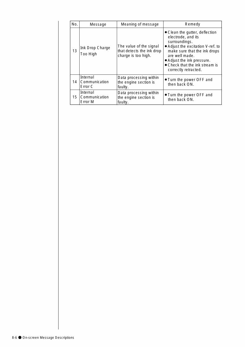
8-6● On-screen Message Descriptions
14
13
No. Message Meaning of message Remedy
The value of the signalthat detects the ink dropcharge is too high.
¡Clean the gutter, deflectionelectrode, and itssurroundings.
¡Adjust the excitation V-ref. tomake sure that the ink dropsare well made.
¡Adjust the ink pressure.¡Check that the ink stream is
correctly retracted.
Ink Drop Charge
Too High
Data processing withinthe engine section isfaulty.
InternalCommunicationError C
¡Turn the power OFF andthen back ON.
15Data processing withinthe engine section isfaulty.
InternalCommunicationError M
¡Turn the power OFF andthen back ON.
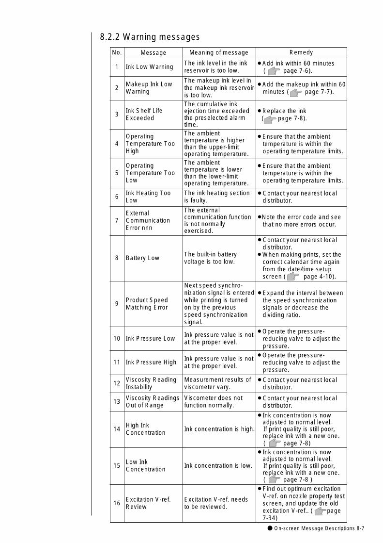
● On-screen Message Descriptions 8-7
9
8.2.2 Warning messages
No. Message
The ink level in the inkreservoir is too low.1
2
¡Add ink within 60 minutes( page 7-6).
Ink Low Warning
Meaning of message Remedy
The makeup ink level inthe makeup ink reservoiris too low.
¡Add the makeup ink within 60minutes ( page 7-7).
Makeup Ink LowWarning
3
The cumulative inkejection time exceededthe preselected alarmtime.
¡Replace the ink ( page 7-8).
Ink Shelf LifeExceeded
4
The ambienttemperature is higherthan the upper-limitoperating temperature.
¡Ensure that the ambienttemperature is within theoperating temperature limits.
OperatingTemperature TooHigh
5
The ambienttemperature is lowerthan the lower-limitoperating temperature.
¡Ensure that the ambienttemperature is within theoperating temperature limits.
OperatingTemperature TooLow
6 The ink heating sectionis faulty.
¡Contact your nearest localdistributor.
Ink Heating TooLow
8 The built-in batteryvoltage is too low.
¡Contact your nearest localdistributor.
¡When making prints, set thecorrect calendar time againfrom the date/time setupscreen ( page 4-10).
Battery Low
7
The externalcommunication functionis not normallyexercised.
¡Note the error code and seethat no more errors occur.
ExternalCommunicationError nnn
Next speed synchro-nization signal is enteredwhile printing is turnedon by the previousspeed synchronizationsignal.
¡Expand the interval betweenthe speed synchronizationsignals or decrease thedividing ratio.
Product SpeedMatching Error
10 Ink pressure value is notat the proper level.
¡Operate the pressure-reducing valve to adjust thepressure.
Ink Pressure Low
11 Ink pressure value is notat the proper level.
¡Operate the pressure-reducing valve to adjust thepressure.
Ink Pressure High
12 Measurement results ofviscometer vary.
¡Contact your nearest localdistributor.
Viscosity ReadingInstability
13 Viscometer does notfunction normally.
¡Contact your nearest localdistributor.
Viscosity ReadingsOut of Range
14 Ink concentration is high.
¡Ink concentration is nowadjusted to normal level.If print quality is still poor,replace ink with a new one.( page 7-8)
High InkConcentration
15 Ink concentration is low.
¡Ink concentration is nowadjusted to normal level.If print quality is still poor,replace ink with a new one.( page 7-8 )
Low InkConcentration
16 Excitation V-ref. needsto be reviewed.
¡Find out optimum excitationV-ref. on nozzle property testscreen, and update the oldexcitation V-ref.. ( page7-34)
Excitation V-ref.Review
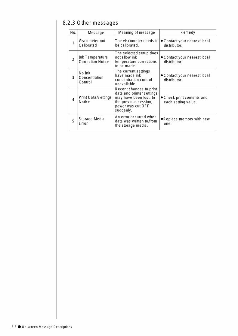
8-8● On-screen Message Descriptions
8.2.3 Other messages
No. Message
The viscometer needs tobe calibrated.1 ¡Contact your nearest local
distributor.Viscometer notCalibrated
Meaning of message Remedy
2
The selected setup doesnot allow inktemperature correctionsto be made.
¡Contact your nearest localdistributor.
Ink TemperatureCorrection Notice
3
The current settingshave made inkconcentration controlunavailable.
¡Contact your nearest localdistributor.
No InkConcentrationControl
4
Recent changes to printdata and printer settingsmay have been lost. Inthe previous session,power was cut OFFsuddenly.
¡Check print contents andeach setting value.
Print Data/SettingsNotice
5An error occurred whendata was written to/fromthe storage media.
¡Replace memory with newone.
Storage MediaError
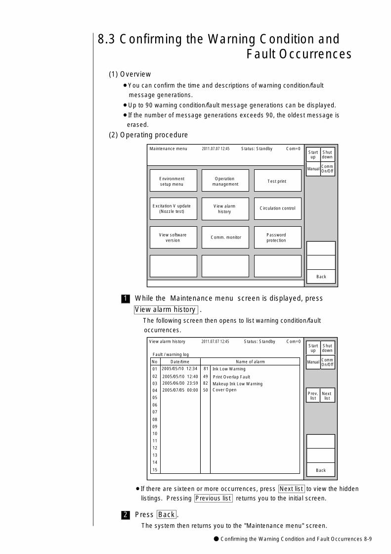
● Confirming the Warning Condition and Fault Occurrences 8-9
2
1
8.3 Confirming the Warning Condition and Fault Occurrences
(1) Overview
¡You can confirm the time and descriptions of warning condition/fault
message generations.
¡Up to 90 warning condition/fault message generations can be displayed.
¡If the number of message generations exceeds 90, the oldest message is
erased.
(2) Operating procedure
Status: Standby Com=0Maintenance menu 2011.07.07 12:45
Environmentsetup menu
Operation management
Test print
Excitation V update(Nozzle test)
View softwareversion
View alarmhistory
Circulation control
Passwordprotection
Comm. monitor
Back
Manual
Startup
Shutdown
CommOn/Off
While the Maintenance menu screen is displayed, press
View alarm history .
The following screen then opens to list warning condition/fault
occurrences.
¡If there are sixteen or more occurrences, press Next list to view the hidden
listings. Pressing Previous list returns you to the initial screen.
No Date/time Name of alarm
01
02
03
04
05
06
07
08
09
10
11
12
13
14
15
View alarm history 2011.07.07 12:45
Fault / warning log
2005/05/10 12:34 81 Ink Low Warning
Print Overlap Fault
Makeup Ink Low WarningCover Open
Status: Standby Com=0
Manual
Back
Prev.list
Next list
Startup
Shutdown
CommOn/Off
2005/05/10 12:40 49
2005/06/30 23:59 82
2005/07/05 00:00 50
Press Back .
The system then returns you to the "Maintenance menu" screen.
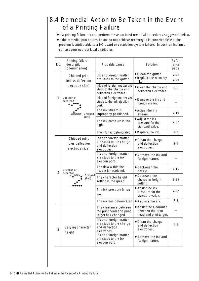
8-10● Remedial Action to Be Taken in the Event of a Printing Failure
7-21
7-29
2-5
-
7-19
7-32
7-8
2-5
-
7-15
3-35
7-32
7-8
-
2-5
-
8.4 Remedial Action to Be Taken in the Event of a Printing Failure
¡If a printing failure occurs, perform the associated remedial procedures suggested below.
¡If the remedial procedures below do not achieve recovery, it is conceivable that the
problem is attributable to a PC board or circulation system failure. In such an instance,
contact your nearest local distributor.
Printing failure Refe- No. description Probable cause Solution rence
(phenomenon) page
¡Clean the gutter.¡Replace the recovery
filter.
¡Clean the charge anddeflection electrodes.
¡Remove the ink and foreign matter.
¡Adjust the ink stream.
¡Adjust the ink pressure for the standard value.
¡Replace the ink.
¡Clean the charge and deflection electrodes.
¡Remove the ink andforeign matter.
¡Backwash the nozzle.
¡Decrease the character height setting.
¡Adjust the ink pressure for the standard value.
¡Replace the ink.
¡Adjust the clearance between the print head and print target.
¡Clean the charge and deflectionelectrodes.
¡Remove the ink and foreign matter.
Ink and foreign matterare stuck to the gutter.
Ink and foreign matter are stuck to the charge anddeflection electrodes.Ink and foreign matter arestuck to the ink ejectionport.The ink stream is improperly positioned.
The ink pressure is too high.
The ink has deteriorated.
Ink and foreign matterare stuck to the chargeand deflectionelectrodes.Ink and foreign matter are stuck to the inkejection port.
The flow within thenozzle is restricted.
The character height setting is too great.
The ink pressure is toolow.
The ink has deteriorated.
The clearance betweenthe print head and printtarget has changed.Ink and foreign matterare stuck to the chargeand deflectionelectrodes.Ink and foreign matterare stuck to the inkejection port.
1
2
3Varying character
height
Chipped print
(plus deflection
electrode side)
Chipped print
(minus deflection
electrode side)
←Chipped (lost)
Direction ofdeflection
←Chipped (lost)
Direction ofdeflection
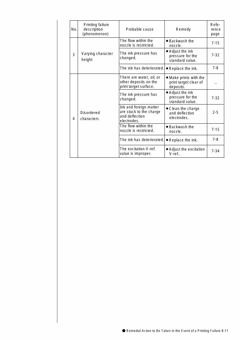
● Remedial Action to Be Taken in the Event of a Printing Failure 8-11
Printing failure Refe- No. description Probable cause Remedy rence
(phenomenon) page
¡Backwash the nozzle.
¡Adjust the ink pressure for the standard value.
¡Replace the ink.
¡Make prints with theprint target clear of deposits.
¡Adjust the ink pressure for the standard value.
¡Clean the charge and deflection electrodes.
¡Backwash thenozzle.
¡Replace the ink.
¡Adjust the excitationV-ref..
The flow within thenozzle is restricted.
The ink pressure has changed.
The ink has deteriorated.
There are water, oil, orother deposits on theprint target surface.
The ink pressure haschanged.
Ink and foreign matter are stuck to the chargeand deflectionelectrodes.The flow within thenozzle is restricted.
The ink has deteriorated.
The excitation V-ref.value is improper.
7-15
7-32
7-8
-
7-32
2-5
7-15
7-8
7-34
3
4
Disordered
characters
Varying character
height
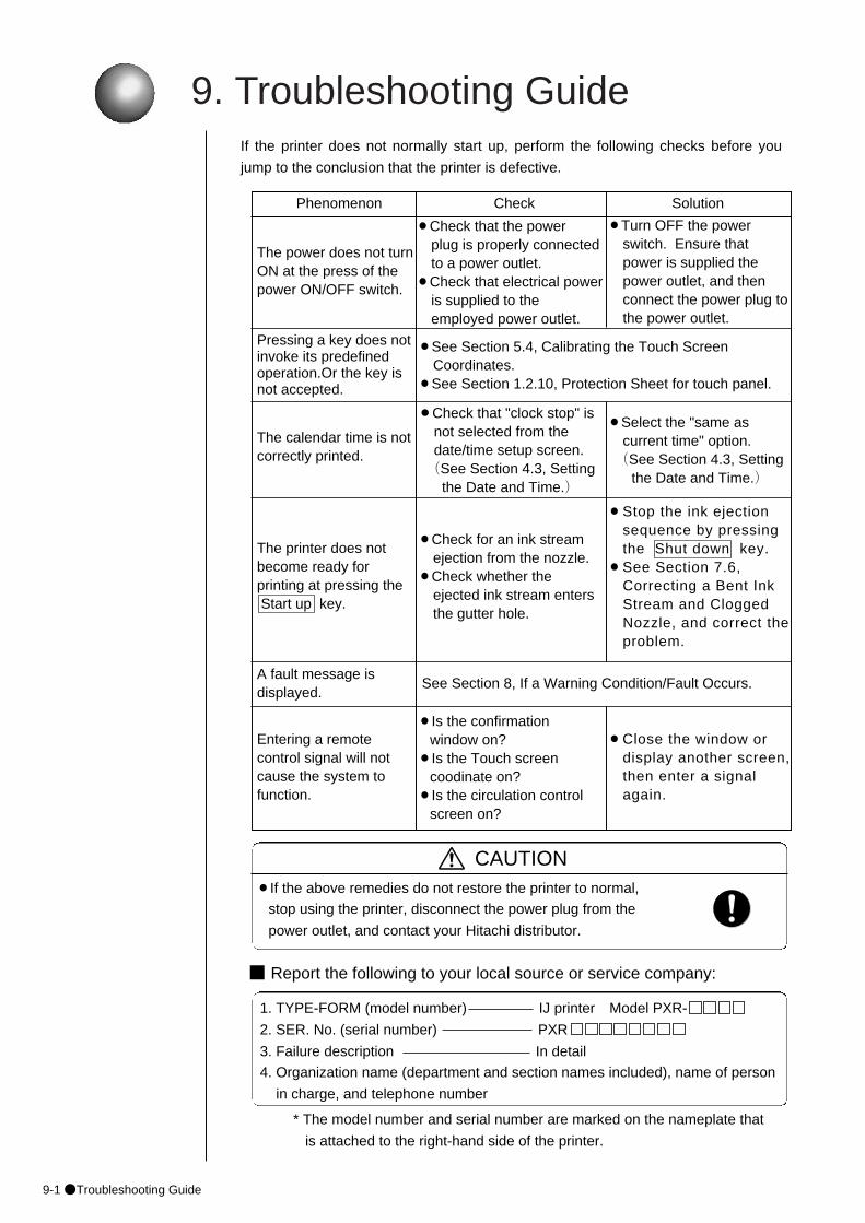
9. Troubleshooting Guide
9-1●Troubleshooting Guide
A fault message is displayed.
Pressing a key does notinvoke its predefinedoperation.Or the key is not accepted.
¡Select the "same as current time" option.(See Section 4.3, Setting
the Date and Time.)
¡Turn OFF the power switch. Ensure that power is supplied the power outlet, and then connect the power plug to the power outlet.
See Section 8, If a Warning Condition/Fault Occurs.
If the printer does not normally start up, perform the following checks before you
jump to the conclusion that the printer is defective.
Phenomenon Check Solution
The power does not turnON at the press of thepower ON/OFF switch.
The printer does not become ready for printing at pressing theStart up key.
¡Check that the power plug is properly connectedto a power outlet.
¡Check that electrical power is supplied to the employed power outlet.
¡Check for an ink stream ejection from the nozzle.
¡Check whether the ejected ink stream enters the gutter hole.
¡Stop the ink ejection sequence by pressing the Shut down key.
¡See Section 7.6, Correcting a Bent Ink Stream and Clogged Nozzle, and correct theproblem.
CAUTION¡If the above remedies do not restore the printer to normal,
stop using the printer, disconnect the power plug from the
power outlet, and contact your Hitachi distributor.
■ Report the following to your local source or service company:
1. TYPE-FORM (model number) IJ printer Model PXR-
2. SER. No. (serial number) PXR
3. Failure description In detail
4. Organization name (department and section names included), name of person
in charge, and telephone number
* The model number and serial number are marked on the nameplate that
is attached to the right-hand side of the printer.
¡See Section 5.4, Calibrating the Touch Screen Coordinates.
¡See Section 1.2.10, Protection Sheet for touch panel.
The calendar time is notcorrectly printed.
¡Check that "clock stop" is not selected from the date/time setup screen.(See Section 4.3, Setting
the Date and Time.)
Entering a remote control signal will not cause the system to function.
¡Is the confirmation window on?
¡Is the Touch screen coodinate on?
¡Is the circulation control screen on?
¡Close the window or display another screen, then enter a signal again.
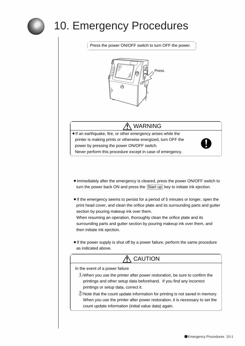
●Emergency Procedures 10-1
10. Emergency Procedures
2
In the event of a power failure
When you use the printer after power restoration, be sure to confirm the
printings and other setup data beforehand. If you find any incorrect
printings or setup data, correct it.
Note that the count update information for printing is not saved in memory.
When you use the printer after power restoration, it is necessary to set the
count update information (initial value data) again.
1
Press the power ON/OFF switch to turn OFF the power.
WARNING¡If an earthquake, fire, or other emergency arises while the
printer is making prints or otherwise energized, turn OFF the
power by pressing the power ON/OFF switch.
Never perform this procedure except in case of emergency.
¡Immediately after the emergency is cleared, press the power ON/OFF switch to
turn the power back ON and press the Start up key to initiate ink ejection.
¡If the emergency seems to persist for a period of 5 minutes or longer, open the
print head cover, and clean the orifice plate and its surrounding parts and gutter
section by pouring makeup ink over them.
When resuming an operation, thoroughly clean the orifice plate and its
surrounding parts and gutter section by pouring makeup ink over them, and
then initiate ink ejection.
¡If the power supply is shut off by a power failure, perform the same procedure
as indicated above.
CAUTION
Press.
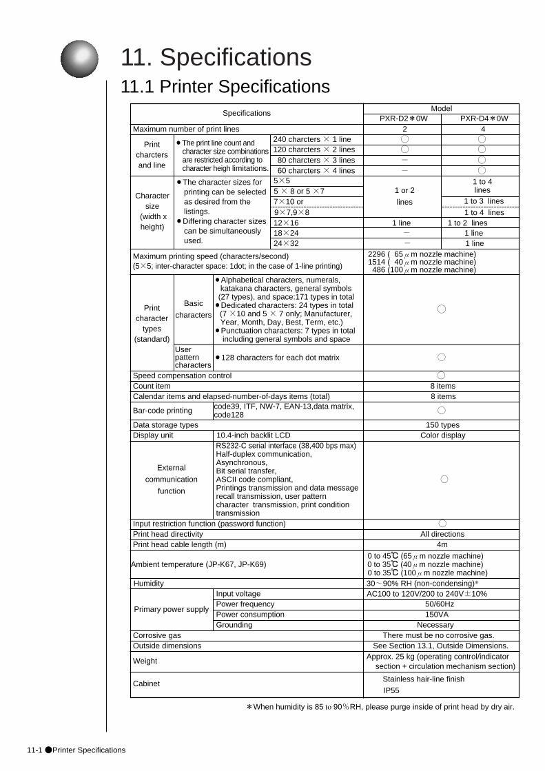
11. Specifications
11-1●Printer Specifications
CabinetStainless hair-line finish
IP55
Humidity 30~90% RH (non-condensing)*
11.1 Printer Specifications
Outside dimensions See Section 13.1, Outside Dimensions.
18×24 - 1 line
Charactersize
(width xheight)
¡The character sizes forprinting can be selected as desired from the listings.
¡Differing character sizescan be simultaneously used.
Maximum number of print lines 2 4
Approx. 25 kg (operating control/indicator section + circulation mechanism section)
Specifications
Printcharctersand line
240 charcters × 1 line ◯ ◯
5×5
Maximum printing speed (characters/second)(5×5; inter-character space: 1dot; in the case of 1-line printing)
External
communication
function
Basic
characters
Print head directivity All directions Print head cable length (m) 4m
0 to 45℃ (65μm nozzle machine) Ambient temperature (JP-K67, JP-K69) 0 to 35℃ (40μm nozzle machine)
0 to 35℃ (100μm nozzle machine)
Input voltage
Corrosive gas There must be no corrosive gas.
120 charcters × 2 lines ◯ ◯80 charcters × 3 lines - ◯60 charcters × 4 lines - ◯
5 × 8 or 5 ×77×10 or
12×16 1 line 1 to 2 lines
24×32 - 1 line
¡Alphabetical characters, numerals, katakana characters, general symbols
(27 types), and space:171 types in total¡Dedicated characters: 24 types in total
(7 ×10 and 5 × 7 only; Manufacturer,Year, Month, Day, Best, Term, etc.)
¡Punctuation characters: 7 types in total including general symbols and space
Userpatterncharacters
¡128 characters for each dot matrix
Speed compensation control ◯Count item 8 itemsCalendar items and elapsed-number-of-days items (total) 8 items
Bar-code printing
Display unit 10.4-inch backlit LCD Color displayRS232-C serial interface (38,400 bps max) Half-duplex communication,Asynchronous,Bit serial transfer,ASCII code compliant,Printings transmission and data message recall transmission, user patterncharacter transmission, print condition transmission
◯
Input restriction function (password function) ◯
Power frequency 50/60HzPower consumption 150VAGrounding Necessary
Weight
ModelPXR-D2*0W PXR-D4*0W
¡The print line count andcharacter size combinationsare restricted according to character heigh limitations.
Printcharacter
types(standard)
◯
◯
Primary power supply
9×7,9×8
1 or 2
lines
1 to 4lines
1 to 4 lines
1 to 3 lines
2296 ( 65μm nozzle machine)1514 ( 40μm nozzle machine)486 (100μm nozzle machine)
*When humidity is 85 to 90%RH, please purge inside of print head by dry air.
Data storage types 150 types
code39, ITF, NW-7, EAN-13,data matrix,code128 ◯
AC100 to 120V/200 to 240V±10%
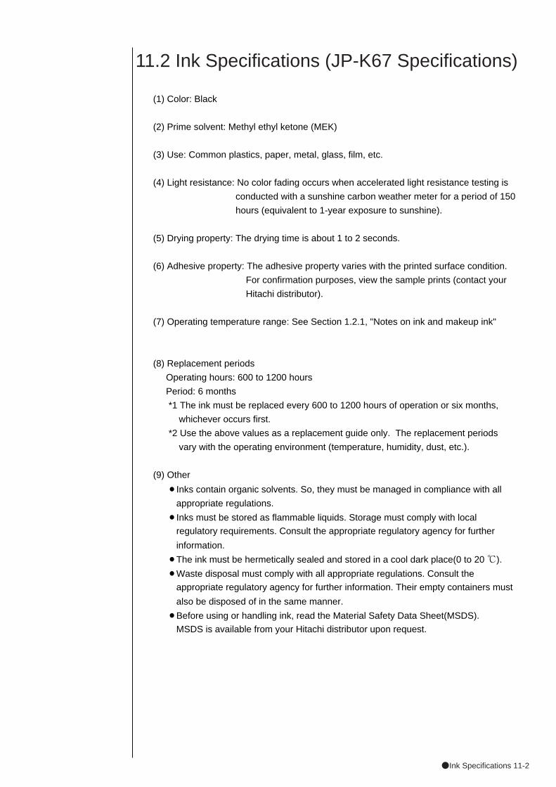
●Ink Specifications 11-2
11.2 Ink Specifications (JP-K67 Specifications)
(1) Color: Black
(2) Prime solvent: Methyl ethyl ketone (MEK)
(3) Use: Common plastics, paper, metal, glass, film, etc.
(4) Light resistance: No color fading occurs when accelerated light resistance testing is
conducted with a sunshine carbon weather meter for a period of 150
hours (equivalent to 1-year exposure to sunshine).
(5) Drying property: The drying time is about 1 to 2 seconds.
(6) Adhesive property: The adhesive property varies with the printed surface condition.
For confirmation purposes, view the sample prints (contact your
Hitachi distributor).
(7) Operating temperature range: See Section 1.2.1, "Notes on ink and makeup ink"
(8) Replacement periods
Operating hours: 600 to 1200 hours
Period: 6 months
*1 The ink must be replaced every 600 to 1200 hours of operation or six months,
whichever occurs first.
*2 Use the above values as a replacement guide only. The replacement periods
vary with the operating environment (temperature, humidity, dust, etc.).
(9) Other
¡Inks contain organic solvents. So, they must be managed in compliance with all
appropriate regulations.
¡Inks must be stored as flammable liquids. Storage must comply with local
regulatory requirements. Consult the appropriate regulatory agency for further
information.
¡The ink must be hermetically sealed and stored in a cool dark place(0 to 20 ℃).
¡Waste disposal must comply with all appropriate regulations. Consult the
appropriate regulatory agency for further information. Their empty containers must
also be disposed of in the same manner.
¡Before using or handling ink, read the Material Safety Data Sheet(MSDS).
MSDS is available from your Hitachi distributor upon request.

12-1●Maintenance
12. Maintenance
1 Ink filter 2,400 hr "7.9 Ink Filter Replacement"
3 Recovery filter 1,200 hr "7.10 Recovery Filter Replacement"
4 Air filter 2,400 hr See the next page.
¡To maintain the IJ printer in an optimum operating condition, it is necessary to
perform the following maintenance programs.
¡If you use the JP-K31A, you have to perform maintenance programs other than
stated below. See "(4) Ink differences and handling precautions" (1.2.1 Notes on
ink and makeup ink).
(1) Consumables replacement
Periodically replace the following filters.
Approximate Replacement procedure No. Consumable replacement reference sectionintervals
2 Circulation filter 2,400 hr "7.11 Circulation Filter Replacement"
¡Operating time of 2400 hours is equivalent to a 1-year operation that is
performed 8 hours a day, 25 days a month.
¡The minimum retention periods of replacement parts (including consumable
parts) are 7 years after closing manufacturing.
¡When you order consumable parts,inform the parts name and the parts code.
No. Consumable Parts name Parts code Note
1 Ink filter
3 Recovery filter Nozzle flat
451037filter 75
4 Air filter Air filter parts 451594 3 pieces/1 pack
2 Circulation filter PTFE filter 451487 2 pieces/1 pack
20 pack 2
Ink filter parts 451590 Nominally 10 μm
(2) Other maintenance programsa. Check for abnormal sound generation from the pump at about 1-week
intervals.b. Before verifying the print results at the beginning of each day's operations,
check that the pressure value is optimal. (For the verification procedure, see Section 7.12, Pressure Adjustment.)
c. For ink drop and excitation voltage checkout, see Section 7.13, Excitation Setting Adjustment , and Section 7.14, Ink Drop Generation Status Checkout Procedure.
(3) Parts to be replaced periodicallyThe clock battery, circulation system parts (pump, solenoid valve, etc.), and heating unit need periodic replacement. Consult your Hitachi distributor.
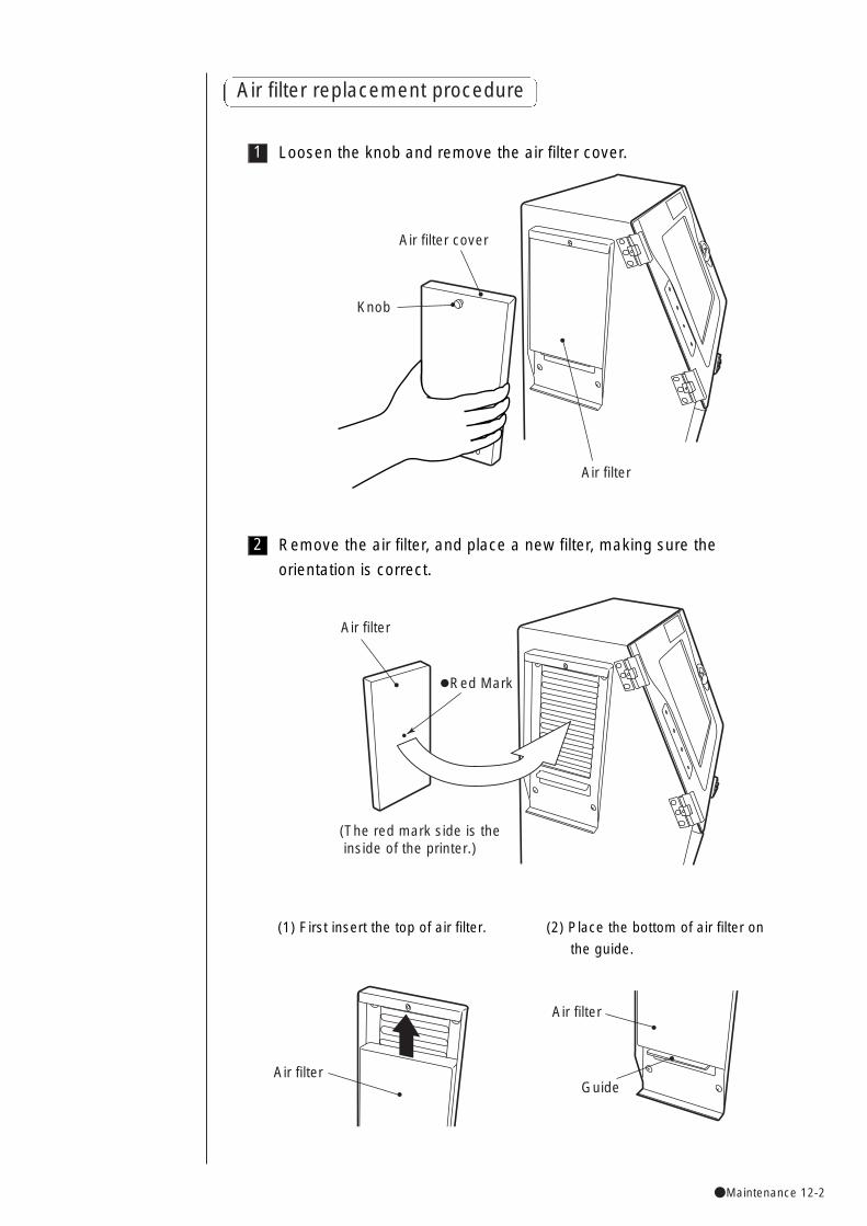
●Maintenance 12-2
Air filter replacement procedure
1 Loosen the knob and remove the air filter cover.
2 Remove the air filter, and place a new filter, making sure the
orientation is correct.
Air filter
Red Mark
(The red mark side is the inside of the printer.)
Air filter cover
Air filter
Knob
Air filter
Air filter
Guide
(1) First insert the top of air filter. (2) Place the bottom of air filter on
the guide.
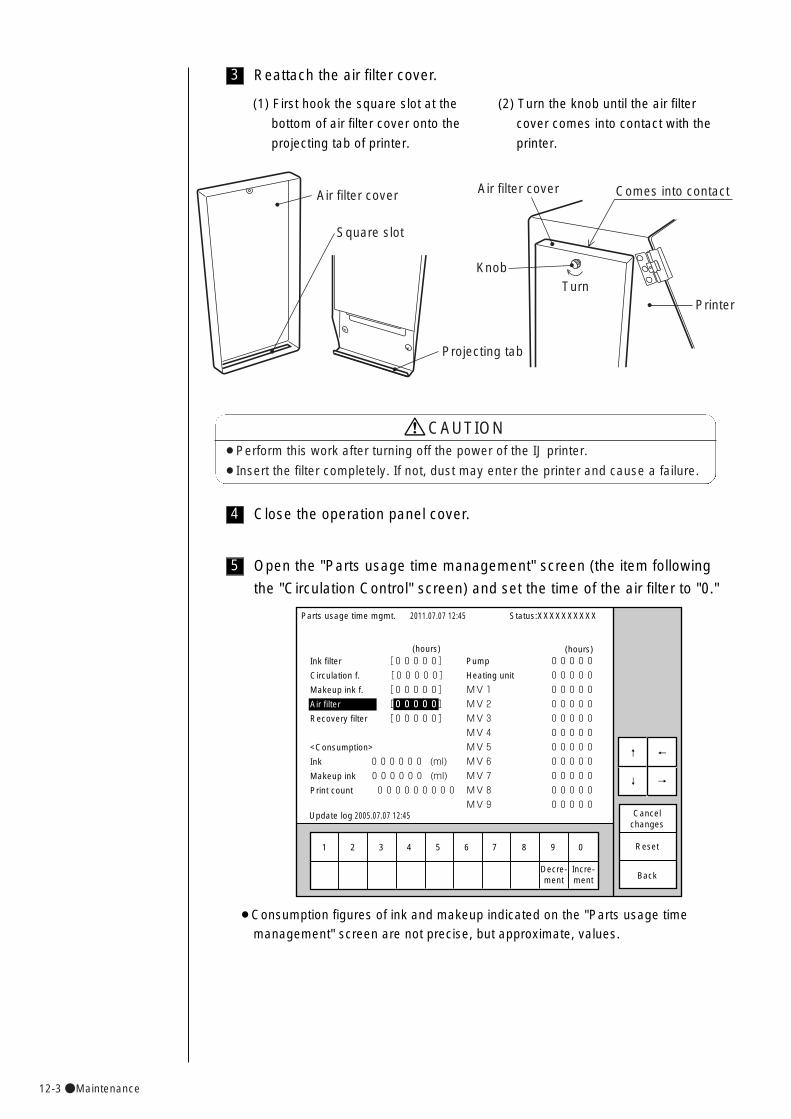
12-3●Maintenance
¡Perform this work after turning off the power of the IJ printer.
¡Insert the filter completely. If not, dust may enter the printer and cause a failure.
CAUTION
4 Close the operation panel cover.
5 Open the "Parts usage time management" screen (the item following
the "Circulation Control" screen) and set the time of the air filter to "0."
1 2 3 4 5 6 7 8 9 0
Incre-ment
Decre-ment
Parts usage time mgmt.
Ink filter [00000]
Circulation f. [00000]
Makeup ink f. [00000]
Air filter [00000]
Recovery filter [00000]�
�
<Consumption>�
Ink 000000 (ml)�
Makeup ink 000000 (ml)�
Print count 000000000�
2011.07.07 12:45
Back
Cancelchanges
Reset
Status:XXXXXXXXXX
←�
→�
↑�
↓�
(hours)Pump 00000
Heating unit 00000
MV1 00000
MV2 00000
MV3 00000
MV4 00000
MV5 00000
MV6 00000
MV7 00000
MV8 00000
MV9 00000
(hours)
Update log 2005.07.07 12:45
�
¡Consumption figures of ink and makeup indicated on the "Parts usage time
management" screen are not precise, but approximate, values.
3 Reattach the air filter cover.
Air filter cover Air filter cover
Square slot
Projecting tab
KnobTurn
Printer
Comes into contact
(1) First hook the square slot at the
bottom of air filter cover onto the
projecting tab of printer.
(2) Turn the knob until the air filter
cover comes into contact with the
printer.
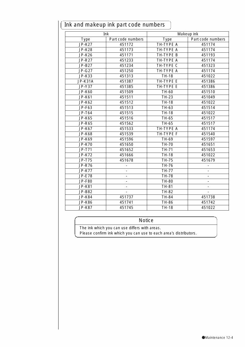
●Maintenance 12-4
Ink Makeup inkType Part code numbers Type Part code numbers
JP-K27 451172 TH-TYPE A 451174JP-K28 451173 TH-TYPE A 451174JP-K26 451171 TH-TYPE B 451193JP-R27 451233 TH-TYPE A 451174JP-B27 451234 TH-TYPE C 451323JP-G27 451250 TH-TYPE A 451174JP-K33 451313 TH-18 451022
JP-K31A 451387 TH-TYPE E 451386JP-Y37 451385 TH-TYPE E 451386JP-K60 451509 TH-60 451510JP-K61 451511 TH-23 451049JP-K62 451512 TH-18 451022JP-F63 451513 TH-63 451514JP-T64 451515 TH-18 451022JP-K65 451516 TH-65 451517JP-R65 451562 TH-65 451517JP-K67 451533 TH-TYPE A 451174JP-K68 451539 TH-TYPE F 451540JP-K69 451596 TH-69 451597JP-K70 451650 TH-70 451651JP-T71 451652 TH-71 451653JP-K72 451666 TH-18 451022JP-T75 451678 TH-75 451679JP-R76 - TH-76 -JP-K77 - TH-77 -JP-E78 - TH-78 -JP-F80 - TH-80 -JP-K81 - TH-81 -JP-B82 - TH-82 -JP-K84 451737 TH-84 451738JP-K86 451741 TH-86 451742JP-K87 451745 TH-18 451022
Ink and makeup ink part code numbers
The ink which you can use differs with areas.Please confirm ink which you can use to each area's distributors.
Notice
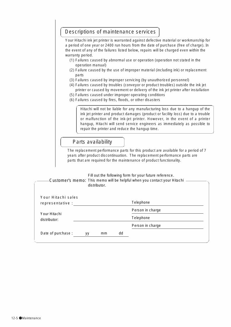
12-5●Maintenance
Descriptions of maintenance services
Your Hitachi ink jet printer is warranted against defective material or workmanship fora period of one year or 2400 run hours from the date of purchase (free of charge). Inthe event of any of the failures listed below, repairs will be charged even within thewarranty period.
(1) Failures caused by abnormal use or operation (operation not stated in the operation manual)
(2) Failure caused by the use of improper material (including ink) or replacementparts
(3) Failures caused by improper servicing (by unauthorized personnel)(4) Failures caused by troubles (conveyor or product troubles) outside the ink jet
printer or caused by movement or delivery of the ink jet printer after installation(5) Failures caused under improper operating conditions (6) Failures caused by fires, floods, or other disasters
Hitachi will not be liable for any manufacturing loss due to a hangup of theink jet printer and product damages (product or facility loss) due to a troubleor malfunction of the ink-jet printer. However, in the event of a printerhangup, Hitachi will send service engineers as immediately as possible torepair the printer and reduce the hangup time.
Parts availability
The replacement performance parts for this product are available for a period of 7years after product discontinuation. The replacement performance parts areparts that are required for the maintenance of product functionality.
Customer's memo: Fill out the following form for your future reference. This memo will be helpful when you contact your Hitachidistributor.
Your Hi tachi sales
representat ive : Telephone
Person in charge
Telephone
Person in charge
Your Hitachi
distributor:
Date of purchase : yy mm dd
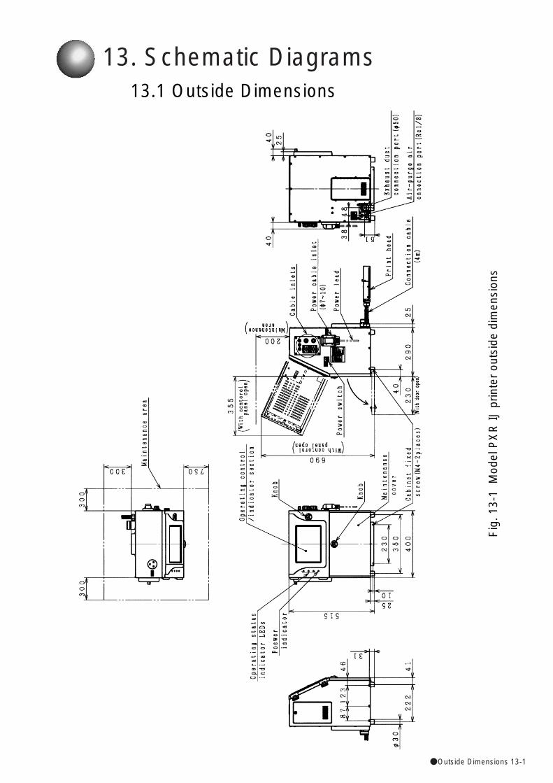
●Outside Dimensions 13-1
13. Schematic Diagrams13.1 Outside Dimensions
Fig
. 13-
1 M
odel
PX
R IJ
prin
ter
outs
ide
dim
ensi
ons
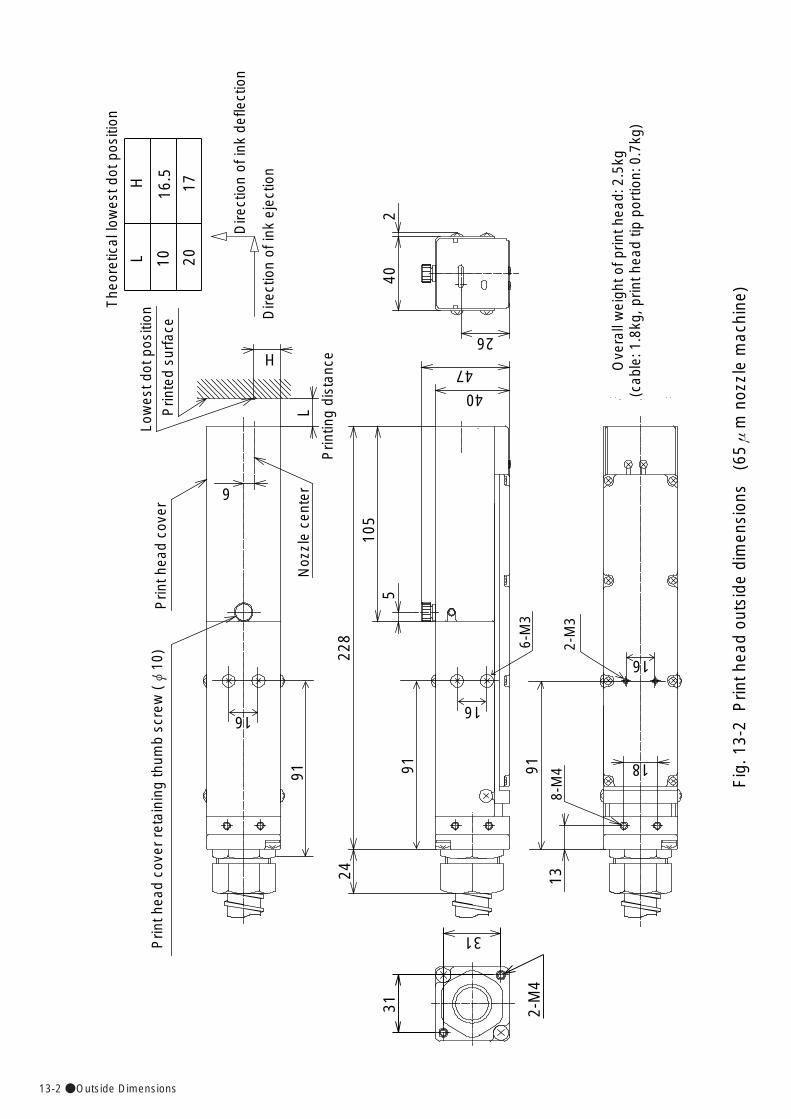
13-2●Outside Dimensions
Fig
. 13-
2 P
rint h
ead
outs
ide
dim
ensi
ons
(65μ
m n
ozzl
e m
achi
ne)
Prin
ted
surf
ace
The
oret
ical
low
est d
ot p
ositi
on
Dire
ctio
n of
ink
defle
ctio
n
Dire
ctio
n of
ink
ejec
tion
Low
est d
ot p
ositi
on
Prin
ting
dist
ance
Prin
t hea
d co
ver
Noz
zle
cent
er
Prin
t hea
d co
ver
reta
inin
g th
umb
scre
w (φ
10)
91
1691
16
6-M
391
8-M
4
16
2-M
3
Ove
rall
wei
ght o
f prin
t hea
d: 2
.5kg
(cab
le: 1
.8kg
, prin
t hea
d tip
por
tion:
0.7
kg)
402
26
47
40
105
5
228
13
1824
2-M
4
31
31
6
L
H
LH
10 20
16.5
17
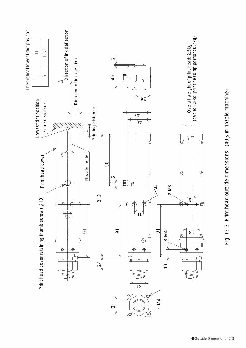
●Outside Dimensions 13-3
Fig
. 13-
3 P
rint h
ead
outs
ide
dim
ensi
ons
(40μ
m n
ozzl
e m
achi
ne)
Prin
ted
surf
ace
The
oret
ical
low
est d
ot p
ositi
on
Dire
ctio
n of
ink
defle
ctio
n
Dire
ctio
n of
ink
ejec
tion
Low
est d
ot p
ositi
on
Prin
ting
dist
ance
Prin
t hea
d co
ver
Noz
zle
cent
er
Prin
t hea
d co
ver
reta
inin
g th
umb
scre
w (φ
10)
91
16
91
16
6-M
391
16
2-M
3
Ove
rall
wei
ght o
f prin
t hea
d: 2
.5kg
(cab
le: 1
.8kg
, prin
t hea
d tip
por
tion:
0.7
kg)
240
26
4740
905
213
8-M
4 18
132-
M4
31
31
24
6
L
H
LH
515
.5
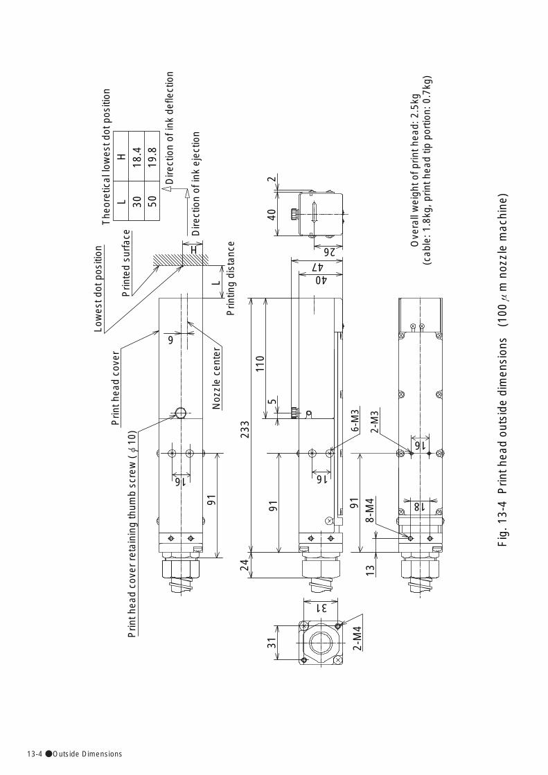
13-4●Outside Dimensions
Fig
. 13-
4 P
rint h
ead
outs
ide
dim
ensi
ons
(10
0μm
noz
zle
mac
hine
)
91
16
91
16
6-M
391
16
2-M
3
Ove
rall
wei
ght o
f prin
t hea
d: 2
.5kg
(cab
le: 1
.8kg
, prin
t hea
d tip
por
tion:
0.7
kg)
240
2647
40
110
5
233
24
8-M
4 18
13
31
31
2-M
4
L
H
LH
30 5018
.419
.8
Dire
ctio
n of
ink
defle
ctio
n
Dire
ctio
n of
ink
ejec
tion
Prin
ted
surf
ace
The
oret
ical
low
est d
ot p
ositi
onLo
wes
t dot
pos
ition
Prin
ting
dist
ance
Prin
t hea
d co
ver
Noz
zle
cent
er
Prin
t hea
d co
ver
reta
inin
g th
umb
scre
w (φ
10)
6
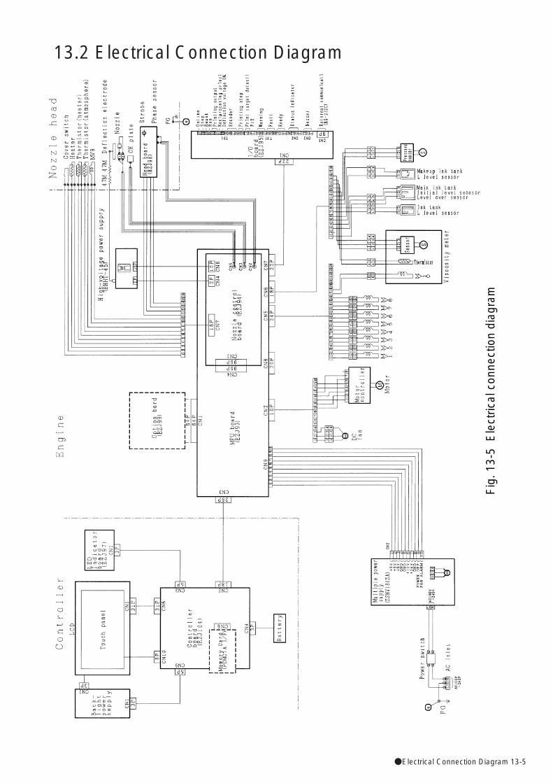
●Electrical Connection Diagram 13-5
13.2 Electrical Connection Diagram
Fig
. 13-
5 E
lect
rical
con
nect
ion
diag
ram

13-6●Circulation System Diagram
13.3 Circulation System Diagram
Fig
. 13-
6 C
ircul
atio
n sy
stem
dia
gram
●Terms and definitions 14-1
A
■<Abort> keyThis key is used to abort the ongoing process
execution.
■<Apply> keyThis is used to give an instruction to reflect it in
printing.
■Auto-phase
This function is used to form, with the timing varied,
a small amount of electric charge on ink particles
that are not targeted for printing, and detect the
timing of ink particle generation by sensing the
voltage at the time of gutter recovery. It is
instrumental in searching for the charge timing
appropriate for printing. If the charge timing is
improperly adjusted, proper prints will not be
obtained.
■Auxiliary functionsUser-created data management and maintenance
functions. Manage message, create user pattern,
copy data, calibrate touch screen coordinates, select
language, and edit standard pattern functions are
available.
■Auxiliary function menuThe auxiliary function menu screen allows you to
initiate manage message, create user pattern, copy
data, calibrate touch screen coordinates, select
language, or edit standard pattern execution.
B
■<Back> key
This key is pressed to return to the previous screen.
■<Backspace> keyIn a character or numerical value input sequence, this
key is pressed to erase the character or numerical
value to the left of the current cursor position.
→ (cf.) <Delete> key
14. Appendix
Terms and definitions
■Blank (character)This is a character that means that "no character"
exists as the print content. Characters positioned
subsequently to this "no character" will not be printed.
When the print contents are displayed by the print
content creation screen, this "no character" character
is represented by the "・" mark.
C
■Calendar characters
Characters for defining the "year," "month," "day,"
"hour," "minute" and "second"of date/time values.
They are shaded when they are displayed as the
printings within the print content creation screen.
■Calendar conditions
This is a feature that is used to define the offset, use
of substitutions, zero suppression, and other
calendar character attributes. It is called up from the
edit message screen.
■Calendar offset
This is a feature that is used to add the calendar
values to the offset values and use the results of
addition as the printings. When determining the
calendar year/month offset, you can choose between
"offset from yesterday" and "from today."
■Calendar time
Time on which calendar value calculations are
based. While the date/time setup screen is displayed
as a maintenance menu option, you can effect
calendar time changeover between "same as current
time" and "clock stop."
■Calendar values
Date and time values that correspond to calendar
characters.
■Calibrate touch screen coordinatesThis function is exercised so that the position of touch
panel depression coincides with the display position.
It is called up from the auxiliary function menu.
■Change message nameThis function is used to change the message names
of saved print data.
14-2●Terms and definitions
■Cover open state
State in which the ink is being ejected, no deflection
voltage is applied, and the print head cover is open.
■Create messagesFunction for editing/registering print data which
differs from data being printed. Started from Auxiliary
function menu.
■Create user pattern User pattern creation function. It is called up from the
auxiliary function menu.
D
■Date/time setupThis function is used to update the current time and
calendar time. It can also be used to effect
changeover between 24- and 12-hour clock systems.
It is called up from the environment setup menu.
■<Dedicated> keyWhile the character input screen is displayed, this key
is used to display the dedicated character keyboard.
■Dedicated characters"Manufacture", "Best", "Term", and other standard
supported patterns. They can be used with the 5 x 8
and 7 x 10 character sizes. They are underlined
when they are displayed as printings within the print
description screen.
■Deflection voltageVoltage applied to the deflection electrodes for the
purpose of bending the flying direction of charged ink
particles.
■<Delete> keyIn a character or numerical value input sequence, this
key is pressed to erase the character or numerical
value at the current cursor position.
→ (cf.) <Backspace> key
■Delete stored messageThis function is used to delete saved print data.
■Dot mixturePrint data having equal column counts and inter-
column spaces in all rows and equal character sizes
and inter-character spaces in all print items are
defined as data containing "no dot mixture."
■Drop adjust stateState in which the ink is being ejected, no deflection
voltage is applied, the nozzle head cover is installed,
and the auto-phase is not established.
■Change message number This function effects message number changes by
interchanging two print data.
■Charge voltageVoltage to be applied to the charge electrode for the
purpose of charging ink particles.
■Circulation controlThis is a feature that institutes procedures in relation
to the ink circulation system. The procedures are for
ink drainage, ink refilling, ink circulation, nozzle
backwash, gutter cleaning, makeup ink refilling,
pressure relief, eject ink, cleaning stop, no-cleaning
stop, ink stream alignment, ink replacement, ink filter
replacement, process prior to long-term shut down,
and process after long-term shut down.
This feature is called up from the maintenance menu.
■Circulation system environment setup
With this, you can set a value for ink concentration
control. Start it when you are on the second screen of
the circulation control menu.
■<Clear> key
While the user pattern creation screen is displayed,
this key is used to clear the on-screen pattern.
■ColumnVertical array of print items.
■Communication environment setupThis feature is used to enter various setup data about
external communication. It is called up from the
environment setup menu.
■Confirmation message
The confirmation message window opens to point out
an operating error, indicate operating steps, or
prompt for process selection.
■Copy dataThis function copies print data and user pattern data
on a Memory card. Start it on the auxiliary function
menu.
■Count charactersCharacters for defining the count control digits.
They are shaded when they are displayed as the
printings within the print content creation screen.
■ Count conditionsThe count character range, update unit, and other
count character settings can be entered. This count
condition setup feature is to be called up from the
character input screen.
●Terms and definitions 14-3
H
■Heating unitThis unit functions to maintain the ink temperature at
an appropriate level.
■High-speed printingWhen the character size setting is 5×7 dots, and
print line is set to 2 or 3 lines, three modes: HS, MS
or LS can be selected with the setting of particle use
rate 1/1. By selecting the mode, you can get the
almost the same print quality as particle use rate
setting 1/2 for the line that you can't set to the particle
use rate 1/2 and should be set to 1/1 at the previous
software.
I
■Ink drop use percentageThe ratio of flying ink particle use. When a ratio os
1/3 is selected, one out of every three particles will
be used for printing, with the remaining two particles
unconditionally recovered from the gutter.
This value is saved together with the print data.
■ Ink stream positionThe ink position prevailing within the gutter bore
when the ink particle flow reaches the gutter with no
deflection voltage applied. If the ink stream position
does not coincide with the optimum position, illegal
printing or ink spillage from the gutter may result.
■<Insert> keyIn a character input sequence, this key is used to
switch between the insertion and overwrite modes.
■<Invert dot> keyWhile the create user pattern screen is displayed,
this key is used to reverse the dot at the current
cursor position.
L
■LineOne line of print items that comprise a column.
The lowermost line is line 1.
■<Duplicate> keyWhile the substitution rule setup screen is displayed,
this key copies the data at the preceding position to
the item position over which the cursor is currently
positioned.
E
■Edit messageThis function is used to enter characters as print
contents. It is called up from the print description
screen. In addition to fixed characters, calendar
and count characters are entered here.
■Edit standard pattern A function of arbitrarily editing a dot pattern of the
standard characters (alphabetical characters,
numbers and symbols). Start it from the auxiliary
function menu.
■Excitation frequencyExcitation voltage frequency.
■Excitation setup updateThis function changes the excitation setting. Start it
while you are on the maintenance menu.
■Excitation voltageThis voltage is applied to a device that converts
electrical vibrations to mechanical vibrations.
The resultant vibrations cause the nozzle to oscillate,
thereby atomizing the ink.
■Excitation V-ref.The span between the maximum and minimum
excitation voltage values is divided into 20 segments,
which are then designated 0 through 19. One of such
20 values is referred to as the excitation voltage
value.
F■Fault
An error that inhibits the printer from continuing to
make prints. If a fault occurs while the printer is
ready for printing, the deflection voltage supply is
shut off.
The ink ejection operation may stop or continue
depending on the type of the fault. → (cf.) Warning
■Faulty stateState in which a fault exists.
14-4●Terms and definitions
■On-line (Com=1)
State in which communication with an external
device can be established. In this state, no
print data changes can be made.
■Operation management
This is a feature that indicates the operating status
and displays the current values concerning the
printer operation. It is to be called up from the print
description screen or the maintenance menu.
P
■Parts usage time managementThis function displays the operation time of the ink
filter and other circulation parts.
Start it when you are on the second page of the
circulation control menu.
■Password protectionThis is a feature that specifies whether print data
changes are to be inhibited or permitted. It is called
up from the maintenance menu screen. → (cf.)
Password setup/update
■Password setup/updateThis function is used to update the password that is
to be entered for password protection purposes. It is
called up from the environment setup menu.
■Print dataA collection of printings, print format, and print
specifications setup data. You can assign a
message name to print data and save or recall it.
■Print description screenThis screen offers a feature that allows you to enter
and edit the printings, print format, and other print
data. It also permits you to recall existing print data or
save new one.
■Print formatThis is a feature that enables you to define the
character size, inter-character space, bar code, and
other print item attributes. It is to be called up from
the print description screen.
■PrintingsCharacter strings to be printed. The print description
screen has an area for displaying printings.
■Print itemUnit of printings. Up to 10 characters (digits) can be
entered for each print item. As a standard feature, up
to 8 print items can be set up for each print data.
M
■MaintenanceThis function provides the management and
maintenance of various operating environment
factors.
■Maintenance menuThe maintenance menu screen allows you to call up
the environment setup menu, operation management,
test print, excitation V update, view alarm history,
circulation control, view software version, comm.
monitor and password protection.
■Makeup inkThis liquid is to be mixed with the ink for the purpose
of adjusting the ink concentration and compensating
for ink component insufficiency.
■Manage messageSaved print data can be managed. The manage
message feature offers the change message number,
delete stored message, and change message name
functions. It is to be called up from the
auxiliary function menu screen.
■<Manual> keyThis key is constantly displayed at the upper right-
hand corner of the display screen. When you press
the <Manual> key, a window opens, prompting you to
select one of the three subkeys. The subkeys provide
three functions: eject ink, no-cleaning stop, and
deflection voltage control functions.
■Message nameName assigned to print data.
N
■Nozzle property testThis function determines an excitation V-ref. for good
printout quality while you change the excitation
setting. Start it when you are on the excitation
update.
O
■Off-line (Com=0)
State in which communication with an external
device cannot be established.
■<OK> keyThis key is pressed to accept the on-screen contents
and proceed to the next step.
●Terms and definitions 14-5
■<Select> key(1) While the print description screen is displayed,
this key is used to open the select message
screen.
(2) While the user pattern creation function is
selected, this key is used to open the select
pattern screen.
(3) While print data listings are displayed, this key is
used to select print data to be processed.
■Selection(1) Function used to recall saved print data from
the print description screen.
(2) Function used to recall a saved user pattern
from the create user pattern screen.
■Service stateState in which the circulation control function is being
executed
■SetColumns in which the line count, line spacing, and
character size arrangements are the same. Up to
four sets can be preselected for each print data.
■Shift codeThis function is used to divide a day into multiple
work shifts and print a different code for each work
shift.
■Solution checkThis check is performed to determine whether an
encountered fault persists or is cleared. When
the encountered fault permits a solution check,
the <Reset> key is displayed within a fault window.
■Starting process in progressState in which the preparations for ink ejection are
being made. This state terminates the moment the
printer switches to the standby state.
■Standby stateState in which the ink is being ejected, no deflection
voltage is applied, the nozzle head cover is installed,
and the auto-phase is established.
■Stopping process in progressThis state prevails between the instant at which ink
ejection is stopped and the instant at which the printer
goes into the inactive state.
■Stop processThis process is performed to stop an ink ejection
operation and switch to the inactive state.
■Stop stateState in which the ink is stopped.
■Print layoutThis is a feature that provides a means of positioning
rectangular frames with reference to the images to be
printed. The print layout appears on the print
description screen.
■Print line setupThis is a feature that defines the number of lines.
When the "overall column setup" method is chosen,
all the columns will be targeted. When the "individual
column setup" method is selected, only the
designated column will be targeted.
This feature is called up from the print description
screen.
■ Print specificationsThis is a feature that allows you to enter the character
height, character width, print start delay, and other
printing-related setup data. It is to be called up from
the print description screen.
■Product speed matchingBased on the encoder signal that is proportional to
the print target transport speed, this feature exercises
print control so as to maintain a fixed character width.
■Pulse rate division FactorDefinition of the ratio of encoder signal referencing.
The value "1/12" means that one reception occurs
every 12 signals.
R
■Ready for printingState in which the ink is being ejected with the
deflection voltage applied. In this state, prints can be
made upon receipt of the print target detection signal.
S
■<Save> key(1) While the print description screen is displayed,
this key is used to switch to the save message
screen.
(2) While the create user pattern function is used,
this key effects switching to the pattern save
screen.
■Saving(1) Function for saving on-screen print data from
the print description screen.
(2) Function for saving an on-screen user pattern
from the create user pattern screen.
14-6●Terms and definitions
V
■View alarm historyThis function is used to display the time and name of
90 newest fault/warning events. It is called up
from the maintenance menu.
■View software versionThis is a feature that displays the names and
versions of installed software. It is called up from the
maintenance menu.
W
■WarningError that permits the ongoing printing operation to
continue but requires the execution of a certain
maintenance task. → (cf.) Fault
■Week numberUse this function when you want to print which week
of the year the current week is.
■Speed compensationBased on the encoder signal that is proportional to
the print target transport speed, this function prevents
the print start delay from varying.
■Substitution rulesCharacter string correspondence table that defines
the relationship between calendar characters and
their substitutes.
■Substitution rule setupThis is a feature that allows you to define the
substitution rules. Use this feature to enter
substitution characters into the correspondence table.
This feature is called up from the calendar condition
screen.
T
■Test printThis function is for printing by key operation without
using a sensor. It is used for test printing. Start this
function when you are in the maintenance menu.
■Time countThis function is used to print time count updating in
preset time units.
■Touch screen setupThis function adjusts the backlight lighting time.
Start it when you are on the environment setup menu.
U
■User environment setupThis is a function that is used to enter various printing
method setup data. It is called up from the
environment setup menu screen.
■User patternThis is an arbitrarily created dot pattern that is used
as a character.
■User pattern character→ (syn.) User pattern
■<User pattern> keyWhile the character input screen is displayed, this
key is pressed to display the user pattern character
keyboard.
●Index 14-7
Circulation control............................................7-5,14-2
Circulation environment setup ...............................14-2
Circulation filter replacement .........................7-31,12-1
Circulation system diagram ...................................13-6
Circulation system environment setup.....................7-5
Circulation system operating and adjustment
procedures...........................................................7-1
Cleaning stop ..................................................1-11,7-5
Cleaning the gutter ................................................7-21
Clear key ...............................................................14-2
Code tables ...........................................................6-32
Column ..................................................................14-2
Common transmission sequences ........................6-10
Communication .......................................1-26,1-43,6-1
Communication environment setup.................6-3,14-2
Communication mode..............................................6-3
Communication monitor function ...........................6-50
Communication timing ...........................................6-43
Component names and functions..........................1-16
Confirmation message...........................................14-2
Confirming the warning condition and fault
occurrences .........................................................8-9
Confirming the registered software........................4-16
Connection of signals ............................................1-22
Connection of various signal .................................1-28
Consumable replacement .....................................12-1
Controlling the executable functions......................4-13
Cooling fan fault.......................................................8-4
Copy data ......................................................5-17,14-2
Copying user data on a memory card ...................5-16
Correcting a bent ink stream and
clogged nozzle .............................................7-15,9-1
Correcting the touch panel coordinates...........5-20,9-1
Count characters...................................3-12,3-28,14-2
Count character transmission.......................6-14, 6-41
Count conditions ...................................2-12,3-29,14-2
Count condition transmission .......................6-16, 6-41
Cover open ............................................................2-13
Cover open state ...................................................14-2
Create messages ...................................4-6, 5-27,14-2
Create user pattern .........................................5-9,14-2
Creating a user pattern............................................5-8
Cumulative operating time.......................................4-1
Current time output transmission ..................6-13,6-40
DData format ..............................................................6-2
Date/time setup .......................................3-41,4-9,14-2
Day of the week.............................................3-26,3-37
AAbort key ...............................................................14-1
Adjusting the ink stream position.....................7-5,7-19
Air filter replacement procedure ............................12-2
Air-purging procedure............................................1-13
Ambient temperature.................................1-8,1-12,4-1
Ambient temperature sensor fault ...........................8-4
Appendix................................................................14-1
Apply key.........................................................2-7,14-1
Auto-phase ............................................................14-1
Auxiliary function .....................................2-12,5-1,14-1
Auxiliary function menu .........................................14-1
BBack key ................................................................14-1
Backspace key ......................................................14-1
Bar code ..........................................................3-7,11-1
Basic operating procedures.....................................2-1
Battery Low..............................................................8-7
Baud rate .................................................................6-2
BCC code handling..................................................6-2
Blank (character) ...................................................14-1
Blank print items ......................................................8-5
CCalendar characters ......................................3-12,14-1
Calendar character transmission...................6-10,6-39
Calendar conditions ..............................2-12,3-42,14-1
Calendar condition transmission ...................6-11,6-40
Calendar offset ......................................3-37,3-41,14-1
Calendar time ................................................4-10,14-1
Calendar values.....................................................14-1
Calendar/count ......................................................3-17
Calibrate touch screen coordinates...............5-21,14-1
Changing a message name.....................................5-6
Change message name ..................................5-6,14-1
Change message number ...............................5-6,14-2
Changing the message number ..............................5-1
Character height......................................3-35,6-2,6-22
Character height for condition transmission ............6-2
Character orientation.....................................1-35,3-35
Character size ...................................................3-6,4-6
Character size code table for user pattern
character transmission ......................................6-39
Character unit CH............................................3-40,6-7
Character width ......................................1-41,3-7,3-35
Character width increase.................................1-37,3-7
Charge voltage fault ................................................8-4
Index
14-8●Index
Heating of ink.........................................................1-14
Heating unit ...........................................1-14,12-1,14-3
Heating unit sensor fault ..........................................8-4
High ink concentration .............................................8-7
High-speed printing ...............................3-37,3-49,14-3
IIf a fault occurs at the beginning of an operation.....2-4
If a warning condition/fault occurs ...........................8-1
IJ printer long-term shutdown ..................................1-8
Improper sensor position .........................................8-5
Indications given when a warning condition/
fault occurs ...........................................................8-1
Individual column setup ...........................................3-5
Ink alarm time....................................................4-1,8-7
Ink and makeup ink part code numbers ................12-4
Ink and makeup ink replenishment..........................1-3
Ink circulation...........................................................7-5
Ink differences and handling precautions........1-4,12-1
Ink drainage...........................................................7-45
Ink drop charge too haigh........................................8-6
Ink drop charge too low ...........................................8-3
Ink drop use percentage
........................................1-35,2-9,3-35,3-36,3-37,14-3
Ink filter replacement .......................................7-5,7-22
Ink heating current fault ...................................1-14,8-4
Ink heating too high .........................................1-14,8-4
Ink heating too low...................................................8-7
Ink low ...............................................................8-3,8-7
Ink name..................................................................4-1
Ink operating time ....................................................4-1
Ink drop generation status checkout
procedure ...................................................7-38,12-1
Ink periodic replacement .........................................1-3
Ink pressure.....................................................4-1,7-32
Ink pressure high .....................................................8-7
Ink pressure low ......................................................8-7
Ink refill ....................................................................7-5
Ink replacement .................................................7-5,7-8
Ink replenishment ....................................................7-6
Ink shelf life exceeded .............................................8-7
Ink specifications ...................................................11-2
Ink stream alignment .......................................7-5,7-19
Ink stream position ................................7-15,7-19,14-3
Ink viscosity .............................................................4-1
Insert key ...............................................................14-3
Installing precautions.............................................1-19
Inter-character space ........................................3-7,5-8
Internal communication error C ...............................8-6
Internal communication error M...............................8-6
Internal communication error S ...............................8-4
DC power supply fan fault ......................................8-4
Deflection voltage..........................................1-11,14-2
Deflection voltage fault ............................................8-3
Deflection voltage leakage ......................................8-3
Delete key..............................................................14-2
Delete stored message ...................................5-4,14-2
Deleting stored data ................................................5-4
Details of circulation control.....................................7-5
Disassembling and cleaning the orifice plate ........7-16
Dot mixture ............................................................14-2
Drainage tube....................................................1-2,7-9
Draining the Ink from the Main Ink Tank................7-45
Drop adjust state ...................................................14-2
Duplicate................................................................3-46
Duplicate key .........................................................14-3
EEdit message.................................................3-12,14-3
Editing print data and printing..................................3-1
Editing standard character patterns.......................5-24
Eject ink ...................................................................7-5
Electrical connection diagram................................13-5
Emergency Procedures .........................................10-1
Environment setup menu.........................................4-7
Excessive format count ...........................................8-5
Excitation frequency ...............1-32,1-33,1-36,4-1,14-3
Excitation Setting Adjustment ...............1-14,7-34,12-1
Excitation setup update .........................................14-3
Excitation voltage ..........................................7-37,14-3
Excitation V-ref. ..........4-1,4-6,7-34,7-35,8-7,12-1,14-3
Excitation V-ref. warning..........................................4-6
Excitation V update (Nozzle test) ..........................7-34
External communication........................1-26,1-43,11-1
External communication error nnn...........................8-7
External views .......................................................1-16
FFault.......................................................................14-3
Fault messages .......................................................8-3
Fault signal output .................................................1-29
Faulty state............................................1-29,1-30,14-3
F memory fault M....................................................8-4
F memory fault S ....................................................8-4
GGutter cleaning........................................1-15,7-5,7-21
HHardware error C.....................................................8-4
Header table ..........................................................6-38
●Index 14-9
Operating temperature too low ................................8-7
Operation management...................................4-2,14-4
Operations for modifying the setting contents .........2-7
Output signal ...................................................1-38,4-5
Outside dimensions.......................................11-1,13-1
Overall column setup.......................................3-4,14-4
Overview..................................................................1-1
PParts usage time management
..............................7-28,7-30,7-31,12-3,14-4
Password protection......................................4-13,14-4
Password setup/update.................................4-11,14-4
Power ON automatic online.....................................6-3
Precautions .............................................1-3,1-19,6-53
Pressure adjustment..............................................7-32
Pressure relief .........................................................7-5
Print condition transmission.....................................6-7
Print count ...............................................................4-1
Print data ...............................................................14-4
Print data changeover in progress C .......................8-5
Print data changeover in progress M.......................8-5
Print data changeover in progress S .......................8-5
Print data changeover in progress V .......................8-5
Print data recall/transmission ..................................6-6
Print description.....................................................14-4
Print description screen...................................3-1,14-4
Print format ......................................................3-6,14-4
Print head ..............................................................1-18
Print head air purge ...............................................1-13
Print head cleaning..................................................1-9
Print item .................................................3-2,6-12,14-4
Print layout ......................................................3-1,14-5
Print line setup.................................................3-4,14-5
Print message transfer ACK ....................................6-2
Print output signal............................................1-38,4-5
Print overlap fault.....................................................8-5
Print specifications ........................................3-35,14-5
Print start delay .....................................3-35,6-22,14-5
Print stop signal .....................................................1-33
Print target detector ...............................................1-31
Printer specifications .............................................11-1
Printing calendar characters..................................3-17
Printing characters.................................................3-12
Printing completed.................................................1-38
Printing count.........................................................3-28
Printing count characters.......................................3-28
Printing day of the week ........................................3-26
Printing dedicated characters ................................3-14
Printing fixed characters ........................................3-12
Printing future date and time .................................3-41
Invert dot key .........................................................14-3
Item delivered ..........................................................1-1
LLine........................................................................14-3
Line spacing ............................................................3-6
Long-term shutdown .................................1-8,7-5,7-40
Low ink concentration..............................................8-7
MMain body internal parts arrangement ...................1-17
Main ink tank too full........................................7-45,8-3
Maintenance .................................2-12,2-13,12-1,14-4
Maintenance menu ................................................14-4
Makeup ink........................................1-3,4-1,12-4,14-4
Makeup ink low .................................................8-3,8-7
Makeup ink name ....................................................4-1
Makeup ink refill ..............................................7-5,14-4
Makeup ink replenishment.......................................7-7
Manage message............................................5-1,14-4
Managing created print data....................................5-1
Managing the operations .........................................4-1
Manual key ....................................................1-11,14-4
Memory card .................................................5-16,14-4
Message name..............................................3-47,14-4
NNo-cleaning stop .............................................1-11,7-5
No ink drop charge ..................................................8-3
Noise fault M............................................................8-3
Noise fault S ............................................................8-3
Notes on ink and makeup ink ..................................1-3
Notes on print condition transmission....................6-53
Notes on product speed matching feature use......6-53
Nozzle backwash ............................................7-5,7-15
Nozzle property test ......................................7-36,14-4
Nozzle rubber seal ..........................1-2,2-11,7-42,7-43
Number of comm. bytes ..........................................6-2
OOff-line (Com=0)..............................................6-5,14-4
OFF-ON transition.....................................3-39,4-4,4-8
OK key...................................................................14-4
On-line (Com=1)..............................................6-5,14-4
On-line/Off-line transmission .........................6-12,6-40
Online signal output ...............................................1-42
On-screen message descriptions ............................8-3
Operating hours...............................................1-3,1-12
Operating temperature too high...............................8-7
14-10●Index
Select message.............................................3-48,14-5
Selection................................................................14-5
Selecting languages ..............................................5-22
Service state..........................................................14-5
Set .........................................................................14-5
Setting character height and character
orientation...........................................................3-35
Setting communication environment .......................6-2
Setting print format ..................................................3-6
Setting print lines .....................................................3-3
Setting repeat printing ...........................................3-39
Setting the date and time.........................................4-9
Setting the operating environment...........................4-1
Setting the password .............................................4-11
Setting the user environment...................................4-4
Shift code ......................................................3-54,14-5
Shutdown ..............................................1-11,2-10,7-40
Shutdown (no-cleaning stop) .................................1-11
Signal ON period ...................................................3-39
Signal timimg .........................................................6-43
Situations requiring an air puge.............................1-13
Solution check .......................................................14-5
Specifications ........................................................11-1
Speed compensation ................................4-5,4-8,14-6
Standard character pattern....................................5-24
Standard communication functions .........................6-5
Standby state ..........................................2-8,2-13,14-5
Starting an operation ...............................................2-1
Startup.............................................................2-1,14-5
Startup process to be performed after
long-term shutdown ............................................7-43
Starting process in progress..................................14-5
Status ....................................................................2-13
Stopping process...................................................14-5
Stopping process in progress ................................14-5
Stop state ..............................................................14-5
Storage precautions ................................................1-4
Substitution character undefined .............................8-5
Substitution rule setup...................................3-44,14-6
Substitution rules.....................................3-44,8-5,14-6
TTarget sensor fault ..........................................3-37,8-5
Target sensor filter.................................................3-37
Target sensor timer ...............................................3-37
Target spacing too close .........................................8-5
Terms and definitions ............................................14-1
Test print .......................................................4-19,14-6
Time count.....................................................3-58,14-6
Total days ..............................................................3-20
Touch screen setup.......................................4-17,14-2
Printing in progress................................................1-39
Printing method ...............................................2-9,3-36
Printing the characters indicating the number of
elapsed days ......................................................3-19
Printing week number............................................3-24
Printing with date/time changed to other
characters...........................................................3-44
Printing without entering sensor signals ................4-19
Printings.................................................................14-5
Printings transmission .............................................6-1
Process after long-term shutdown.........................7-43
Process prior to long-term shutdown.......................7-5
Process to be performed prior to long-term
shutdown ............................................................7-40
Product speed matching ...............1-34,3-35,3-37,14-5
Product speed matching error .................................8-7
Protection sheet for touch panel ............................1-15
Pulse rate division factor .......................1-36,3-37,14-5
Pump motor fault .....................................................8-4
RReady for printing ..................................................14-5
Ready output selector switch ........................1-28,1-44
Ready output signal.......................................1-28,1-44
Recalling a user pattern.........................................5-13
Recalling saved data .............................................3-48
Recovery filter replacement...........................7-29,12-1
Remedial action to be taken in the event of
a printing failure ..................................................8-10
Remote control signals ..........................................1-39
Repairing the printer after long-term shutdown .....7-44
Repeat count ...................................................3-39,4-4
Repeat intervals ....................................3-39,6-22,6-38
Repeat print sensor mode .......................................4-4
Replenishment timeout ............................................8-3
Response time.......................................................6-47
Reverse direction printing................................1-38,4-4
Reverse direction printing signal ...........................1-38
Reverse print ...........................................................4-5
Rotary encoder signal............................................1-34
RS-232C .................................................1-26,1-43,6-1
SSave key................................................................14-5
Save message...............................................3-47,14-5
Saving ...........................................................3-47,14-5
Saving a user pattern ..............................................5-8
Saving edited print data.........................................3-47
Scanning unit SC ............................3-35,3-37,3-40,6-7
Schematic diagrams ..............................................13-1
Select key ..............................................................14-5
●Index 14-11
Transmission sequences.......................................6-18
Transmission specifications.....................................6-4
Troubleshooting guide .............................................9-1
UUsage precautions...................................................1-3
User environment setup ..................................4-8,14-6
User pattern ............................................5-8,6-28,14-6
User pattern character ..........................3-12,3-29,14-6
User pattern key ....................................................14-6
User pattern character transmission .........6-1,6-8,6-27
Using the circulation control screen.........................7-2
Using the ready output selector switch..........1-28,1-44
VView alarm history ...........................................8-9,14-6
View software version ...................................4-16,14-6
Viscometer temperature sensor fault......................8-4
Viscosity reading instability......................................8-7
Viscosity readings out of range ...............................8-7
WWarning .................................................................14-6
Warning messages..........................................6-51,8-7
Warning signal output ............................................1-30
Warranty period .....................................................12-4
Wiring Precautions ................................................1-22

3S23L1307-3B (PXR-D) E7(HEC)


![PXR-D RevBUserManual English[1]](https://img.pdfslide.us/doc/110x75/55cf882a55034664618e0bd6/pxr-d-revbusermanual-english1.jpg)