Embed Size (px)
Citation preview
44 www.turbodieselregister.com TDR 72
72i1. The rear of the Bosch CP3 high pressure pump showing the finned cover of the gear type pump at lower right.
The Fuel Control Actuator is lying on the pump and attaches on the rear left side of the pump.
This is a much simpler task and high pressure pumps are matured products. They can readily be made both durable and reliable. The Cummins electronic control system (ECM or engine control module) is also a proven electronic product.
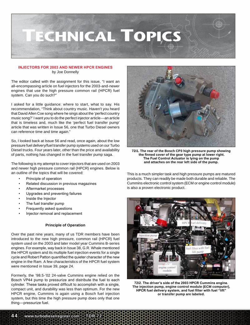
72i2. The driver’s side of the 2003 HPCR Cummins engine. The injection pump, engine control module (ECM computer),
HPCR fuel delivery system, and fuel filter with fuel “lift” or transfer pump are labeled.
INJECTORS FOR 2003 AND NEWER HPCR ENGINESby Joe Donnelly
The editor called with the assignment for this issue, “I want an all-encompassing article on fuel injectors for the 2003-and-newer engines that use the high pressure common rail (HPCR) fuel system. Can you do such?”
I asked for a little guidance: where to start, what to say. His recommendation, “Think about country music. Haven’t you heard that David Allen Coe song where he sings about the ‘perfect country music song?’ I want you to do the perfect injector article—an article that is timeless and, much like the ‘perfect fuel transfer pump’ article that was written in Issue 56, one that Turbo Diesel owners can reference time and time again.”
So, I looked back at Issue 56 and read, once again, about the low pressure fuel delivery/fuel transfer pump systems used on our Turbo Diesel trucks. Four years later, other than the price and availability of parts, nothing has changed in the fuel transfer pump saga.
The following is my attempt to cover injectors that are used on 2003 and newer high pressure common rail (HPCR) engines. Below is an outline of the topics that will be covered:
• Principleofoperation• Relateddiscussioninpreviousmagazines• Aftermarketprocesses• Upgradesandpreventingfailures• InsidetheInjector• Thefueltransferpump• Frequentlyaskedquestions• Injectorremovalandreplacement
Principle of Operation
Over the past nine years, many of us TDR members have been introduced to the new high pressure, common rail (HPCR) fuel system used on the 2003 and later model year Cummins B-series engines. For example, way back in Issue 38, G.R. Whale mentioned the HPCR system and its multiple fuel injection events for a single cycleandRobertPattonquantifiedthequietercharacterofthenewengine in the Ram. A few characteristics of the HPCR fuel system were mentioned in Issue 39, page 24.
Formerly, the ‘98.5-’02 24-valve Cummins engine relied on the BoschVP44pumptopressurizeanddistribute the fuel toeachcylinder.Thesetasksproveddifficulttoaccomplishwithasingle,compact unit, and durability was less than optimum. For the new HPCR engine, Cummins is again using a Bosch fuel injection system, but this time the high pressure pump does only that one thing—pressurizefuel.
TDR 72 www.turbodieselregister.com 45
Technical Topics . . . . Continued
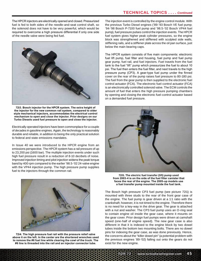
TheHPCRinjectorsareelectricallyopenedandclosed.Pressurizedfuel is fed to both sides of the needle-and-seat control shaft, so the solenoid does not have to be very powerful, which would be requiredtoovercomeahighpressuredifferentialifonlyonesideof the needle valve were being fed fuel.
72i3. Bosch injector for the HPCR system. The extra height of the injector for the new common rail system, compared to older style mechanical injectors, accommodates the electrical control mechanism to open and close the injector. Prior designs on our Turbo Diesels used fuel pressure to open and close the injector.
Electrically operated injectors have been commonplace for a couple of decades in gasoline engines. Again, the technology is reasonably durable and reliable, in addition to being the only practical solution to federal and state emissions mandates.
In Issue 40 we were introduced to the HPCR engine from an emissions perspective. The HPCR system has a rail pressure of up to 23,200 psi (1600 bar). The multiple injection events under such high fuel pressure result in a reduction of 8-10 decibels of noise. Improvedinjectiontimingandpilotinjectionwidensthepeaktorqueband by 400 rpm compared to the earlier ’98.5-’02 24-valve engine with the VP44 injection pump. The high pressure pump supplies fuel to the injectors through the common rail.
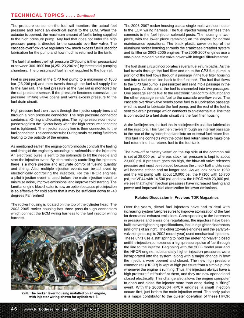
72i4. The high pressure fuel rail with the pressure relief valve above it on the left. In the center are the shortened wrenches used to remove the #6 fuel line while clearing the cowl of the truck. The
#6 line is threaded into the rail and an injector connector tube.
The injection event is controlled by the engine control module. With the previous Turbo Diesel engines (’89-’93 Bosch VE fuel pump; ’94-’98 Bosch P-7100 fuel pump and ’98.5-’02 Bosch VP44 fuel pump), fuel pressure pulses control the injection events. The HPCR fuel system gives higher peak cylinder pressures, so the engine block was strengthened and stiffened with sculpted side walls, stiffening rails, and a stiffener plate across the oil pan surface, just below the main bearing caps.
TheHPCRsystemconsistsoffivemaincomponents:electronicfuel lift pump, fuel filterandhousing, fuelpumpand fuelpumpgear pump, fuel rail, and fuel injectors. Fuel travels from the fuel tanktothefuel“lift”pumpwhichpressurizesthefueltoabout10psi.Thefuelthenentersthefuelfilter,andnexttravelstothehighpressurepump (CP3).Agear-type fuel pumpunder the finnedcover on the rear of the pump raises fuel pressure to 80-180 psi. The fuel from the gear pump is then supplied to the electronic fuel control actuator (FCA). The electronic fuel-control actuator (FCA) is an electronically controlled solenoid valve. The ECM controls the amount of fuel that enters the high pressure pumping chambers by opening and closing the electronic fuel-control actuator based on a demanded fuel pressure.
72i5. The electric fuel transfer (lift) pump used from 2003-4 is on the side of the fuel filter canister that faces the rear of the engine. The 2005-up models use
a fuel transfer pump mounted inside the fuel tank.
The Bosch high pressure CP3 fuel pump (see picture 72i1) is mounted with three studs to the rear of the front gear case of the engine. The fuel pump is gear driven at a 1:1 ratio with the crankshaft; however, it is not timed to the engine. Therefore there is no need for a key-way in the drive gear. The gear is attached with a nut and washer. The CP3 fuel pump uses an O-ring seal to contain engine oil inside the gear case, where it mounts on the gear cover. Prior design fuel pumps were driven at camshaft speed (one-half of engine speed). The new gear case is also different in that it is indexed to the engine block by two dowel tubes inside the bottom two mounting bolts. There are no dowel pins for indexing the gear case, as was done previously. Hence, the concerns about the “killer dowel pin” (a potential problem with the previous engines ’89-’02) falling out onto the gears do not exist for the new engine.
46 www.turbodieselregister.com TDR 72
The pressure sensor on the fuel rail monitors the actual fuel pressure and sends an electrical signal to the ECM. When the actuator is opened, the maximum amount of fuel is being supplied to the high pressure pump. Any fuel that does not enter the high pressure pump is directed to the cascadeoverflow valve. Thecascadeoverflowvalveregulateshowmuchexcessfuelisusedforlubrication for the pump and how much is returned to the tank.
ThefuelthatentersthehighpressureCP3pumpisthenpressurizedto between 300-1600 bar (4,251-23,206 psi) by three radial pumping chambers.Thepressurizedfuelisnextsuppliedtothefuelrail.
FuelispressurizedintheCP3fuelpumptoamaximumof1600bar (23,206 psi) and then travels through the fuel rail supply line to the fuel rail. The fuel pressure at the fuel rail is monitored by the rail pressure sensor. If the pressure becomes excessive, the pressure limiting valve opens and vents excess pressure to the fuel drain circuit.
High pressure fuel then travels through the injector supply lines and through a high pressure connector. The high pressure connector contains an O-ring and locating pins. The high pressure connector pushes against the injector body when the high pressure connector nut is tightened. The injector supply line is then connected to the fuel connector. The connector tube O-ring seals returning fuel from leaking to the outside of the engine.
As mentioned earlier, the engine control module controls the fueling and timing of the engine by actuating the solenoids on the injectors. An electronic pulse is sent to the solenoids to lift the needle and start the injection event. By electronically controlling the injectors, there isamorepreciseandaccuratecontrolof fuelingquantityand timing. Also, multiple injection events can be achieved by electronically controlling the injectors. For the HPCR engines, a pilot injection event is used before the main injection event to minimizenoise,improveemissions,andimprovecoldstarting.Thefamiliar engine block heater is now an option because pilot injection issoeffectiveforcoldstartsthatitmaybesufficientdownto-40degrees Fahrenheit!
The rocker housing is located on the top of the cylinder head. The 2003-2005 rocker housing has three pass-through connectors which connect the ECM wiring harness to the fuel injector wiring harness.
72i6. The rocker lever housing installed on an engine, with injector wiring shown for cylinders 1-3.
The 2006-2007 rocker housing uses a single multi-wire connector to the ECM wiring harness. The fuel injector wiring harness then connects to the fuel injector solenoid posts. The housing is two-piece, with the lower piece remaining on the engine for normal maintenance operations. The black plastic cover on top of the aluminum rocker housing shrouds the crankcase breather system anditsfilteron2003-2005engines.The2006-2007enginesuseaone-piecemoldedplasticvalvecoverwithintegralfilter/breather.
The fuel drain circuit incorporates several fuel return paths. As the fueltravelsthroughthefuelfilterandontotheCP3fuelpump,aportionofthefuelflowsthroughapassageinthefuelfilterhousingandintoafueldrainlinebacktothefueltank.ThefuelthatflowstotheCP3fuelpumpispressurizedandsentintoapassageinthefuel pump. At this point, the fuel is channeled into two passages. One passage sends fuel to the electronic fuel control actuator and theotherpassagesendsfueltothecascadeoverflowvalve.Thecascadeoverflowvalvesendssomefueltoalubricationpassagewhich is used to lubricate the fuel pump, and the rest of the fuel is sent to a drain passage which connects to an external fuel line that isconnectedtoafueldraincircuitviathefuelfilterhousing.
At the fuel injectors, the fuel that is not injected is used for lubrication of the injectors. This fuel then travels through an internal passage to the rear of the cylinder head and into an external fuel return line. This fuel line connects with the other fuel return lines to make one fuel return line that returns fuel to the fuel tank.
The blow-off or “safety valve” on the top side of the common rail is set at 28,000 psi, whereas stock rail pressure is kept to about 23,000 psi. If pressure goes too high, the blow-off valve releases pressure and must be replaced because the check ball and its seat will become etched and no longer seal. As we look back to 1989 and the VE pump with about 10,000 psi, the P7100 with 16,700 psi, the VP44 with 14,500 psi, and now the HPCR with 23,000 psi, we see that higher injection pressures have increased fueling and powerandimprovedfuelatomizationforloweremissions.
Related Discussion in Previous TDR Magazines
Over the years, diesel fuel injectors have had to deal with increasingsystemfuelpressurestoimproveatomizationofthefuelfor decreased exhaust emissions. Corresponding to the increases in pressures and emissions regulations, the injectors have been builttoevertighteningspecifications,includingtighterclearances(millionths of an inch). The older 12-valve engines and the early 24-valve engines (up to 2002 model year) used mechanical injectors. These units use a stiff spring to hold the metering “valve” closed until the injection pump sends a high pressure pulse of fuel through the line to the injector. Beginning with the 2003 model year and the HPCR engine, substantially higher injection pressures were incorporated into the system, along with a major change in how the injectors were opened and closed. The new high pressure common rail (HPCR) is kept at high pressure from a simple pump whenever the engine is running. Thus, the injectors always have a high pressure fuel “pulse” at them, and they are now opened and closed electrically. This change also allows the engine computer toopenandclosetheinjectormorethanonceduringa“firing”event. With the 2003-2004 HPCR engines, a small injection occursfirst,justbeforethemaininjectionevent.Theearlypulseisamajor contributor to thequieteroperationof theseHPCR
Technical Topics . . . . Continued
TDR 72 www.turbodieselregister.com 47
engines compared to earlier engines. For emissions reasons, later engines, the 2004.5 to 2007 model years, went to a total of threeinjectionsperfiringevent.In2007.5andlatermodels(the6.7-liter engine) four injections are used.
Since the focus of this article is a comprehensive look at the HPCR fuel system, there are other removal and installation articles you may want to reference. The following is a comprehensive listing:
• Injector installations, 12-valve, 24-valve, andHPCRwerecovered in TDR Issue 51, page 94.
• AslightlydifferentapproachforremovalandinstallationwaspresentedbyTDRmemberStanGozzi(SAG2),whichfollowsthe Cummins and Chrysler procedures and uses the special Cummins tools, is found in TDR Issue 52, page 46.
• ScottDalgleishvisitedDynomiteDieselPerformance(DDP),ahighqualityaftermarketinjectorshop,anddiscussedtheirinjectors in Issue 56, page 96; Issue 59, page 86.
• Commonrailinjectorlines#4and6haveexperiencedfailures.An updated line with a hold-down bracket was covered in Issue 56, page 108. (see photo 72i7).
• HPCRtopicshavebeencoveredinthe“HaveRamWillTravel”column several times, including Issues 56 (CP3 installation), 62, 63, 69 (injectors)
• Andy Redmond discussed hard starting problems and low fuel pressure testing in Issue 66, pages 124-125.
And, to meet the objective of my assignment, at the end of the article I’ll again cover the removal and installation procedure, complete with updates that I’ve learned through the years.
Overall, high quality aftermarket injectors are a significant andvaluable component of a well-balanced hop-up strategy. These injectors are more involved to install than on earlier trucks. I have found that Stage 1 injectors (50-60hp gain) are a good, moderate compromise, suitable for daily driving, towing, and performance. At a small sacrifice in fuelmileage,Stage 2 injectorsmay besubstituted (DDP Stage 2 injectors are good for a 90hp gain). Stage1injectorsofthequalitysuppliedbyDDPandafewothervendors give similar mileage to stock injectors, or in some driving conditions, a little better than stock.
Aftermarket Processes
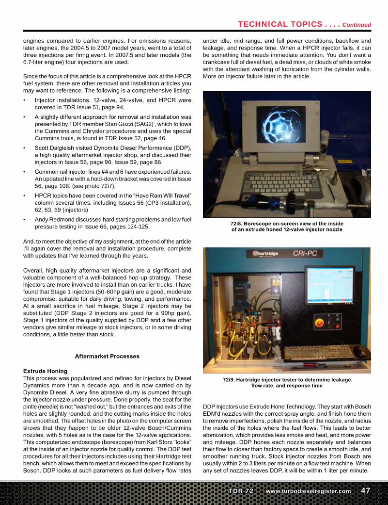
Extrude HoningThisprocesswaspopularizedandrefinedforinjectorsbyDieselDynamics more than a decade ago, and is now carried on by DynomiteDiesel.Averyfineabrasiveslurryispumpedthroughtheinjectornozzleunderpressure.Doneproperly,theseatforthepintle (needle) is not “washed out,” but the entrances and exits of the holes are slightly rounded, and the cutting marks inside the holes are smoothed. The offset holes in the photo on the computer screen shows that they happen to be older 12-valve Bosch/Cummins nozzles,with5holesasisthecaseforthe12-valveapplications.Thiscomputerizedendoscope(borescope)fromKarlStorz“looks”attheinsideofaninjectornozzleforqualitycontrol.TheDDPtestprocedures for all their injectors includes using their Hartridge test bench,whichallowsthemtomeetandexceedthespecificationsbyBosch.DDPlooksatsuchparametersasfueldeliveryflowrates
under idle,mid range, and full power conditions, backflowandleakage, and response time. When a HPCR injector fails, it can be something that needs immediate attention. You don’t want a crankcase full of diesel fuel, a dead miss, or clouds of white smoke with the attendant washing of lubrication from the cylinder walls. More on injector failure later in the article.
72i8. Borescope on-screen view of the inside of an extrude honed 12-valve injector nozzle
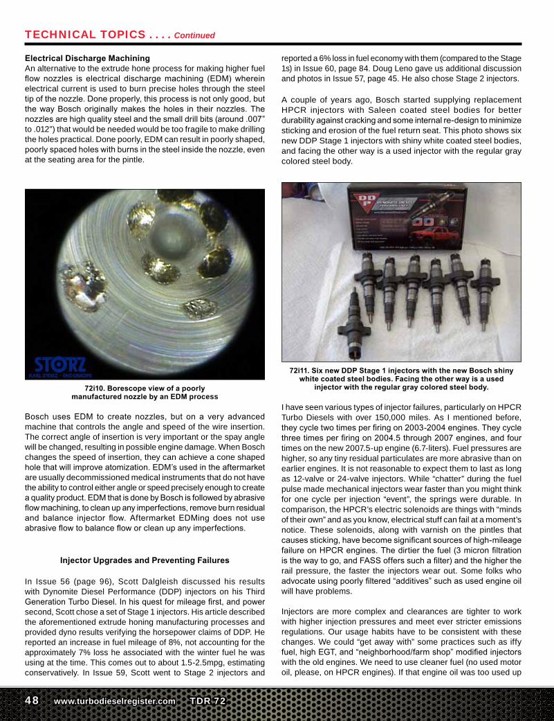
72i9. Hartridge injector tester to determine leakage, flow rate, and response time
DDP Injectors use Extrude Hone Technology. They start with Bosch EDM’dnozzleswiththecorrectsprayangle,andfinishhonethemtoremoveimperfections,polishtheinsideofthenozzle,andradiustheinsideoftheholeswherethefuelflows.Thisleadstobetteratomization,whichprovideslesssmokeandheat,andmorepowerandmileage.DDPhoneseachnozzleseparatelyandbalancestheirflowtocloserthanfactoryspecstocreateasmoothidle,andsmoother running truck.Stock injector nozzles fromBoschareusuallywithin2to3litersperminuteonaflowtestmachine.WhenanysetofnozzlesleavesDDP,itwillbewithin1literperminute.
Technical Topics . . . . Continued
48 www.turbodieselregister.com TDR 72
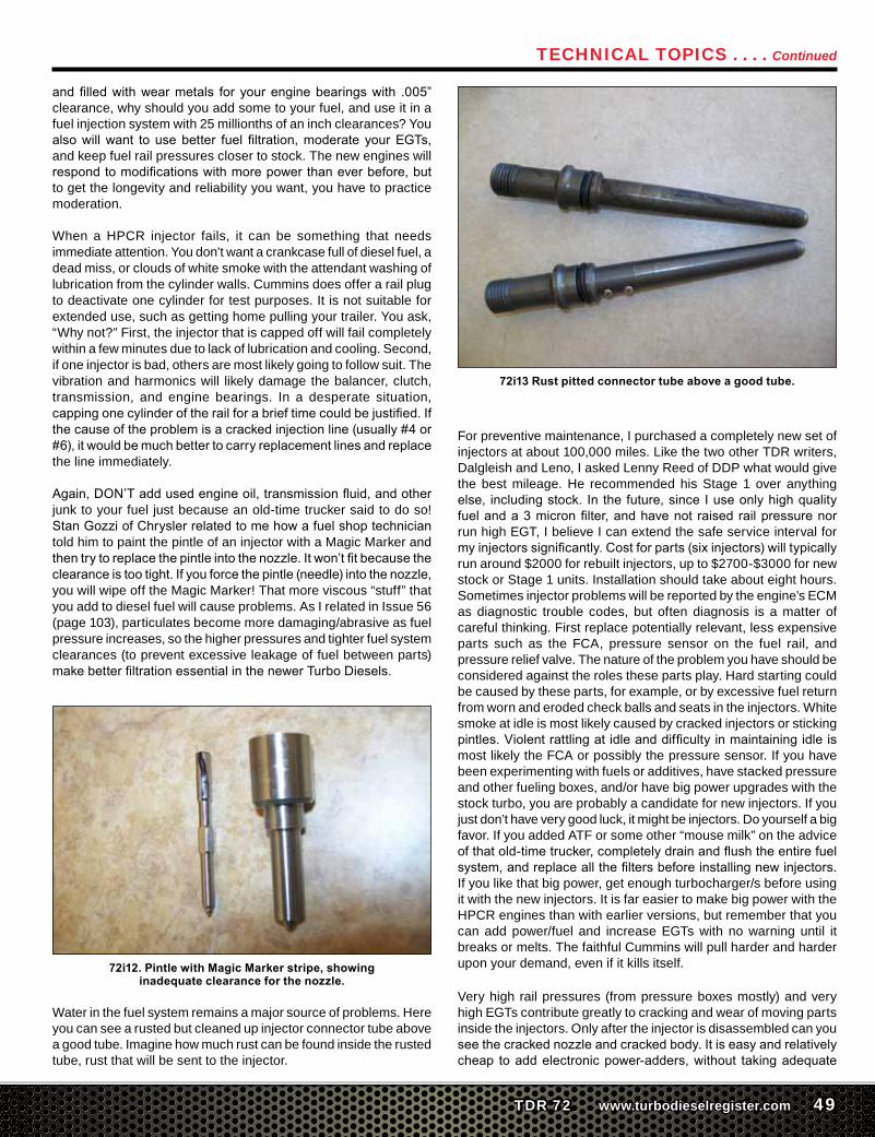
Electrical Discharge MachiningAn alternative to the extrude hone process for making higher fuel flownozzles is electrical dischargemachining (EDM)whereinelectrical current is used to burn precise holes through the steel tipofthenozzle.Doneproperly,thisprocessisnotonlygood,butthewayBoschoriginallymakes theholes in theirnozzles.Thenozzlesarehighqualitysteelandthesmalldrillbits(around.007”to .012”) that would be needed would be too fragile to make drilling the holes practical. Done poorly, EDM can result in poorly shaped, poorlyspacedholeswithburnsinthesteelinsidethenozzle,evenat the seating area for the pintle.
72i10. Borescope view of a poorly manufactured nozzle by an EDM process
Bosch usesEDM to create nozzles, but on a very advancedmachine that controls the angle and speed of the wire insertion. The correct angle of insertion is very important or the spay angle will be changed, resulting in possible engine damage. When Bosch changes the speed of insertion, they can achieve a cone shaped holethatwillimproveatomization.EDM’susedintheaftermarketare usually decommissioned medical instruments that do not have the ability to control either angle or speed precisely enough to create aqualityproduct.EDMthatisdonebyBoschisfollowedbyabrasiveflowmachining,tocleanupanyimperfections,removeburnresidualand balance injector flow. Aftermarket EDMing does not useabrasiveflowtobalancefloworcleanupanyimperfections.
Injector Upgrades and Preventing Failures
In Issue 56 (page 96), Scott Dalgleish discussed his results with Dynomite Diesel Performance (DDP) injectors on his Third GenerationTurboDiesel.Inhisquestformileagefirst,andpowersecond, Scott chose a set of Stage 1 injectors. His article described the aforementioned extrude honing manufacturing processes and provided dyno results verifying the horsepower claims of DDP. He reported an increase in fuel mileage of 8%, not accounting for the approximately 7% loss he associated with the winter fuel he was using at the time. This comes out to about 1.5-2.5mpg, estimating conservatively. In Issue 59, Scott went to Stage 2 injectors and
reported a 6% loss in fuel economy with them (compared to the Stage 1s) in Issue 60, page 84. Doug Leno gave us additional discussion and photos in Issue 57, page 45. He also chose Stage 2 injectors.
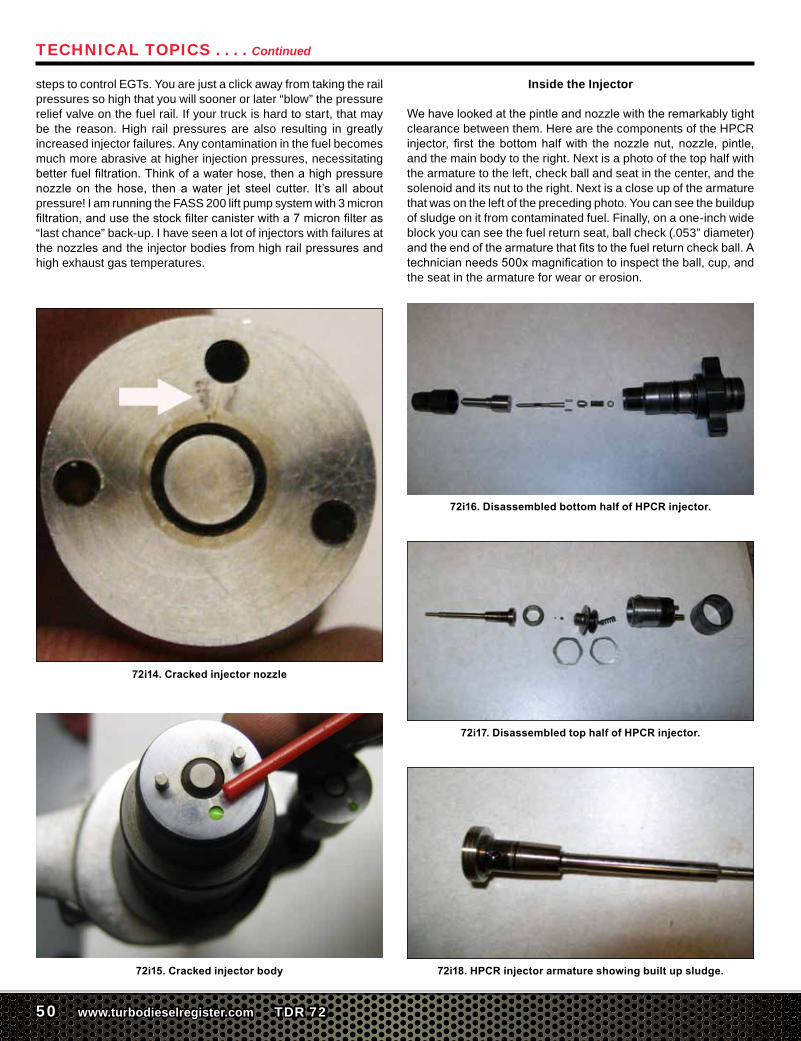
A couple of years ago, Bosch started supplying replacement HPCR injectors with Saleen coated steel bodies for better durabilityagainstcrackingandsomeinternalre-designtominimizesticking and erosion of the fuel return seat. This photo shows six new DDP Stage 1 injectors with shiny white coated steel bodies, and facing the other way is a used injector with the regular gray colored steel body.
72i11. Six new DDP Stage 1 injectors with the new Bosch shiny white coated steel bodies. Facing the other way is a used
injector with the regular gray colored steel body.
I have seen various types of injector failures, particularly on HPCR Turbo Diesels with over 150,000 miles. As I mentioned before, theycycletwotimesperfiringon2003-2004engines.Theycyclethreetimesperfiringon2004.5through2007engines,andfourtimes on the new 2007.5-up engine (6.7-liters). Fuel pressures are higher, so any tiny residual particulates are more abrasive than on earlier engines. It is not reasonable to expect them to last as long as 12-valve or 24-valve injectors. While “chatter” during the fuel pulse made mechanical injectors wear faster than you might think for one cycle per injection “event”, the springs were durable. In comparison, the HPCR’s electric solenoids are things with “minds of their own” and as you know, electrical stuff can fail at a moment’s notice. These solenoids, along with varnish on the pintles that causessticking,havebecomesignificantsourcesofhigh-mileagefailureonHPCRengines.Thedirtierthefuel(3micronfiltrationisthewaytogo,andFASSofferssuchafilter)andthehighertherail pressure, the faster the injectors wear out. Some folks who advocateusingpoorlyfiltered“additives”suchasusedengineoilwill have problems.
Injectors are more complex and clearances are tighter to work with higher injection pressures and meet ever stricter emissions regulations. Our usage habits have to be consistent with these changes. We could “get away with” some practices such as iffy fuel,highEGT,and“neighborhood/farmshop”modifiedinjectorswith the old engines. We need to use cleaner fuel (no used motor oil, please, on HPCR engines). If that engine oil was too used up
Technical Topics . . . . Continued
TDR 72 www.turbodieselregister.com 49
andfilledwithwearmetals for yourenginebearingswith .005”clearance, why should you add some to your fuel, and use it in a fuel injection system with 25 millionths of an inch clearances? You alsowillwant tousebetter fuel filtration,moderate yourEGTs,and keep fuel rail pressures closer to stock. The new engines will respondtomodificationswithmorepowerthaneverbefore,butto get the longevity and reliability you want, you have to practice moderation.
When a HPCR injector fails, it can be something that needs immediate attention. You don’t want a crankcase full of diesel fuel, a dead miss, or clouds of white smoke with the attendant washing of lubrication from the cylinder walls. Cummins does offer a rail plug to deactivate one cylinder for test purposes. It is not suitable for extended use, such as getting home pulling your trailer. You ask, “Why not?” First, the injector that is capped off will fail completely within a few minutes due to lack of lubrication and cooling. Second, if one injector is bad, others are most likely going to follow suit. The vibration and harmonics will likely damage the balancer, clutch, transmission, and engine bearings. In a desperate situation, cappingonecylinderoftherailforabrieftimecouldbejustified.Ifthecauseoftheproblemisacrackedinjectionline(usually#4or#6),itwouldbemuchbettertocarryreplacementlinesandreplacethe line immediately.
Again,DON’Taddusedengineoil,transmissionfluid,andotherjunk to your fuel just because an old-time trucker said to do so! StanGozziofChryslerrelatedtomehowafuelshoptechniciantold him to paint the pintle of an injector with a Magic Marker and thentrytoreplacethepintleintothenozzle.Itwon’tfitbecausetheclearanceistootight.Ifyouforcethepintle(needle)intothenozzle,you will wipe off the Magic Marker! That more viscous “stuff” that you add to diesel fuel will cause problems. As I related in Issue 56 (page 103), particulates become more damaging/abrasive as fuel pressure increases, so the higher pressures and tighter fuel system clearances (to prevent excessive leakage of fuel between parts) makebetterfiltrationessentialinthenewerTurboDiesels.
72i12. Pintle with Magic Marker stripe, showing inadequate clearance for the nozzle.
Water in the fuel system remains a major source of problems. Here you can see a rusted but cleaned up injector connector tube above a good tube. Imagine how much rust can be found inside the rusted tube, rust that will be sent to the injector.
72i13 Rust pitted connector tube above a good tube.
For preventive maintenance, I purchased a completely new set of injectors at about 100,000 miles. Like the two other TDR writers, Dalgleish and Leno, I asked Lenny Reed of DDP what would give the best mileage. He recommended his Stage 1 over anything else, includingstock. In thefuture,sinceIuseonlyhighqualityfuelanda3micronfilter,andhavenot raisedrailpressurenorrun high EGT, I believe I can extend the safe service interval for myinjectorssignificantly.Costforparts(sixinjectors)willtypicallyrun around $2000 for rebuilt injectors, up to $2700-$3000 for new stock or Stage 1 units. Installation should take about eight hours. Sometimes injector problems will be reported by the engine’s ECM as diagnostic trouble codes, but often diagnosis is a matter of careful thinking. First replace potentially relevant, less expensive parts such as the FCA, pressure sensor on the fuel rail, and pressure relief valve. The nature of the problem you have should be considered against the roles these parts play. Hard starting could be caused by these parts, for example, or by excessive fuel return from worn and eroded check balls and seats in the injectors. White smoke at idle is most likely caused by cracked injectors or sticking pintles.Violentrattlingatidleanddifficultyinmaintainingidleismost likely the FCA or possibly the pressure sensor. If you have been experimenting with fuels or additives, have stacked pressure and other fueling boxes, and/or have big power upgrades with the stock turbo, you are probably a candidate for new injectors. If you just don’t have very good luck, it might be injectors. Do yourself a big favor. If you added ATF or some other “mouse milk” on the advice ofthatold-timetrucker,completelydrainandflushtheentirefuelsystem,andreplaceallthefiltersbeforeinstallingnewinjectors.If you like that big power, get enough turbocharger/s before using it with the new injectors. It is far easier to make big power with the HPCR engines than with earlier versions, but remember that you can add power/fuel and increase EGTs with no warning until it breaks or melts. The faithful Cummins will pull harder and harder upon your demand, even if it kills itself.
Very high rail pressures (from pressure boxes mostly) and very high EGTs contribute greatly to cracking and wear of moving parts inside the injectors. Only after the injector is disassembled can you seethecrackednozzleandcrackedbody.Itiseasyandrelativelycheap toaddelectronicpower-adders,without takingadequate
Technical Topics . . . . Continued
50 www.turbodieselregister.com TDR 72
steps to control EGTs. You are just a click away from taking the rail pressures so high that you will sooner or later “blow” the pressure relief valve on the fuel rail. If your truck is hard to start, that may be the reason. High rail pressures are also resulting in greatly increased injector failures. Any contamination in the fuel becomes much more abrasive at higher injection pressures, necessitating betterfuelfiltration.Thinkofawaterhose,thenahighpressurenozzle on the hose, thenawater jet steel cutter. It’s all aboutpressure! I am running the FASS 200 lift pump system with 3 micron filtration,andusethestockfiltercanisterwitha7micronfilteras“last chance” back-up. I have seen a lot of injectors with failures at thenozzlesandtheinjectorbodiesfromhighrailpressuresandhigh exhaust gas temperatures.
72i14. Cracked injector nozzle
72i15. Cracked injector body
Inside the Injector
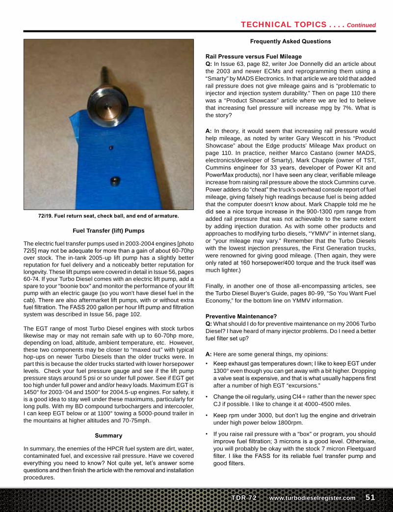
Wehavelookedatthepintleandnozzlewiththeremarkablytightclearance between them. Here are the components of the HPCR injector,first thebottomhalfwith thenozzlenut,nozzle,pintle,and the main body to the right. Next is a photo of the top half with the armature to the left, check ball and seat in the center, and the solenoid and its nut to the right. Next is a close up of the armature that was on the left of the preceding photo. You can see the buildup of sludge on it from contaminated fuel. Finally, on a one-inch wide block you can see the fuel return seat, ball check (.053” diameter) andtheendofthearmaturethatfitstothefuelreturncheckball.Atechnicianneeds500xmagnificationtoinspecttheball,cup,andthe seat in the armature for wear or erosion.
72i16. Disassembled bottom half of HPCR injector.
72i17. Disassembled top half of HPCR injector.
72i18. HPCR injector armature showing built up sludge.
Technical Topics . . . . Continued
TDR 72 www.turbodieselregister.com 51
72i19. Fuel return seat, check ball, and end of armature.
Fuel Transfer (lift) Pumps
The electric fuel transfer pumps used in 2003-2004 engines [photo 72i5]maynotbeadequateformorethanagainofabout60-70hpover stock. The in-tank 2005-up lift pump has a slightly better reputation for fuel delivery and a noticeably better reputation for longevity. These lift pumps were covered in detail in Issue 56, pages 60-74. If your Turbo Diesel comes with an electric lift pump, add a spare to your “boonie box” and monitor the performance of your lift pump with an electric gauge (so you won’t have diesel fuel in the cab). There are also aftermarket lift pumps, with or without extra fuelfiltration.TheFASS200gallonperhourliftpumpandfiltrationsystem was described in Issue 56, page 102.
The EGT range of most Turbo Diesel engines with stock turbos likewise may or may not remain safe with up to 60-70hp more, depending on load, altitude, ambient temperature, etc. However, these two components may be closer to “maxed out” with typical hop-ups on newer Turbo Diesels than the older trucks were. In part this is because the older trucks started with lower horsepower levels. Check your fuel pressure gauge and see if the lift pump pressure stays around 5 psi or so under full power. See if EGT get too high under full power and and/or heavy loads. Maximum EGT is 1450° for 2003-‘04 and 1500° for 2004.5-up engines. For safety, it is a good idea to stay well under these maximums, particularly for long pulls. With my BD compound turbochargers and intercooler, I can keep EGT below or at 1100° towing a 5000-pound trailer in the mountains at higher altitudes and 70-75mph.
Summary
In summary, the enemies of the HPCR fuel system are dirt, water, contaminated fuel, and excessive rail pressure. Have we covered everythingyouneedtoknow?Notquiteyet, let’sanswersomequestionsandthenfinishthearticlewiththeremovalandinstallationprocedures.
Frequently Asked Questions
Rail Pressure versus Fuel MileageQ: In Issue 63, page 82, writer Joe Donnelly did an article about the 2003 and newer ECMs and reprogramming them using a “Smarty” by MADS Electronics. In that article we are told that added rail pressure does not give mileage gains and is “problematic to injector and injection system durability.” Then on page 110 there was a “Product Showcase” article where we are led to believe that increasing fuel pressure will increase mpg by 7%. What is the story?
A: In theory, it would seem that increasing rail pressure would help mileage, as noted by writer Gary Wescott in his “Product Showcase” about the Edge products’ Mileage Max product on page 110. In practice, neither Marco Castano (owner MADS, electronics/developer of Smarty), Mark Chapple (owner of TST, Cummins engineer for 33 years, developer of Power Kit andPowerMaxproducts),norIhaveseenanyclear,verifiablemileageincrease from raising rail pressure above the stock Cummins curve. Power adders do “cheat” the truck’s overhead console report of fuel mileage, giving falsely high readings because fuel is being added that the computer doesn’t know about. Mark Chapple told me he didseeanicetorqueincreaseinthe900-1300rpmrangefromadded rail pressure that was not achievable to the same extent by adding injection duration. As with some other products and approaches to modifying turbo diesels, “YMMV” in internet slang, or “your mileage may vary.” Remember that the Turbo Diesels with the lowest injection pressures, the First Generation trucks, were renowned for giving good mileage. (Then again, they were onlyratedat160horsepower/400torqueandthetruckitselfwasmuch lighter.)
Finally, in another one of those all-encompassing articles, see the Turbo Diesel Buyer’s Guide, pages 80-99, “So You Want Fuel Economy,” for the bottom line on YMMV information.
Preventive Maintenance?Q: What should I do for preventive maintenance on my 2006 Turbo Diesel? I have heard of many injector problems. Do I need a better fuelfiltersetup?
A: Here are some general things, my opinions:• Keepexhaustgastemperaturesdown;IliketokeepEGTunder
1300° even though you can get away with a bit higher. Dropping avalveseatisexpensive,andthatiswhatusuallyhappensfirstafter a number of high EGT “excursions.”
• Changetheoilregularly,usingCI4+ rather than the newer spec CJ if possible. I like to change it at 4000-4500 miles.
• Keeprpmunder3000,butdon’tlugtheengineanddrivetrainunder high power below 1800rpm.
• If you raise rail pressure with a “box” or program, you should improvefuelfiltration;3micronsisagoodlevel.Otherwise,you will probably be okay with the stock 7 micron Fleetguard filter. I like theFASSfor its reliable fuel transferpumpandgoodfilters.
Technical Topics . . . . Continued
52 www.turbodieselregister.com TDR 72
Finding the Bad InjectorQ: My Turbo diesel has a lot of timing rattle noise and rough acceleration around 2000rpm under light throttle. When slowing down, the idle drops down to 500rpm and then recovers.
A: Since the truck is not lighting up the dash with diagnostic trouble codes, it is best to start parts-swapping with the least expensive items. Start with the fuel control actuator (FCA) on the back of the CP3 pump. The FCA is less than $120.
Let’s continue to discuss parts-swapping with the least expensive items. The following is a tip that I picked-up from TDR issue 62 where a TDR member wrote-in with a surging, rough idle and hardstartproblem.Unfortunatelyfortheowner,hehadalreadyreplaced the injectors, an expensive repair. The tip: “Try adding a couple of cans of ashless two-stroke oil to the fuel. If it clears up, it’s a defective fuel control actuator (FCA). The oil lubricates the FCA and the engine will idle until the two-stroke oil is depleted. It’s a cheap diagnosis method and only takes the time to run some treated fuel through it.”
TofinishthestoryfromIssue62,“Iwastoldthataddingafuellubeto check the FCA was a test that STAR (Chrysler tech assistance) was using some time ago. A friend who had a Turbo Diesel with a sticking FCA added fuel lube to it by accident and the truck ran fine.Afteratankandahalfoffuelwithouttheadditive,theroughidle, stalling, and stumbling returned. He had problems similar to yours and everyone was telling him it was defective injectors. As longashekeptthefueladditiveinthetank,theengineranfine.He tried different fuel treatments including Marvel Mystery Oil. I read about the fuel lube test, STAR, and the FCA and told him to replace the FCA. He replaced the FCA and the truck has been running like new without any additives.”
The owner tried the two-stroke oil and the engine did not stumble, but it still idled rough. The dealership replaced the FCA and the problem with the engine was solved.
To check individual injectors on the ’03-’05 Turbo Diesels, you could unplug one of the three electrical connectors at the head, while the engine is not running (the wires carry up to 50-volts). Once you see which pair of cylinders is at fault, you can remove the valve cover and remove one pair of wires at a time. Or, you could go right to the individual injector wires. You will get a trouble code, but you can remove it later. Since other injectors may be “weak” the best approach would be to send all six to a Bosch shop like Dynomite Diesel for testing. They are a Bosch dealer and could sell you new injectors as needed. Obviously, unplugging the injector will serve as a diagnostic method only if the electrical solenoid is at fault. If you have a mechanical failure, you would have to plug off one injector at a time or replace one at a time. DDP could test all six for you if that would be more convenient.
Other Injector SymptomsQ: What are some of the other symptoms that I have an injector-related problem?
A: Often a truck will idle and run rough like it is missing. If it shows a diagnostic trouble code (DTC) P2149-“Fuel Injector Group, 2 Supply Voltage Circuit,” you’ll want to check for a fuel injector solenoid failure or the electrical connection through the valve cover gasket. To check for either problem, the valve cover must be removed.
Disconnect each injector in the bank affected which should be cylinder number 4, 5, and 6 and check the resistance with an ohmmeter. It should check less than 1-ohm and greater than 0 resistance. Look for the odd reading.
Disconnect injector harness outside the valve cover and using an ohmmeter, check each wire for continuity and resistance. The wires should be less than 1 ohm and greater than 0 resistance.
Hard Start = Injector Problem?Q: I have heard that an engine that is hard to start could signal a looming injector(s) problem. Can you explain?
A: Let’s talk about the long crank issue. This is generally created due to the CP3 injection pump not being able to pump up enough pressureinthecommonrailtofiretheinjectors(around5200psi).Thefirstthingtocheckisthetotalfuelreturnvolumetoseethatit doesn’t exceed about 30 ml during a 10-second crank period. Sometimes you can cure the problemby re-torqueing the fueldelivery tubes. Next, check the individual injectors to see that they are returning only 2-6ml during a 10-second crank period.Any injector with a return volume in the 12-14ml range during a 10-second crank period needs to be replaced. This happens when the check ball wears so that it doesn’t seat correctly which, ofcourse,causesaleak.Toconfirmtheproblem,withtheenginecold, cap off each injector during cranking and see which one allows theenginetofireup.
I noted that TDR writer Andy Redmond had presented this Q&A back in Issue 66. The following is how he went about the diagnostics and repair:
“Recently, a 2005 truck arrived with a hard starting problem. Other recent repairs included two remanufactured injectors, but shortly after the injectors were installed the owner complained the hard start problem worsened as did his poor fuel economy. The scan tool was connected and no diagnostic trouble codes (DTC’s) were present. The batteries were tested and found to have a good charge. My next step was to monitor actual and desired rail pressure (psi) during the cranking attempts. After several consecutive cranking cycles the scanner showed pressure increasing from 1000 psi to about 4,000 psi at which time the engine started. Why will the truck not crank until a certain pressure level is met? Simple. At low pressure the ECM programming does notcommandtheinjectorsolenoidstoenergize.Alightmisfirewasobserved at engine idle.
Technical Topics . . . . Continued
TDR 72 www.turbodieselregister.com 53
“The minimum rail psi for engine start is purposefully not stated. Depending upon the scan tool manufacturer and the ECM programming of desired rail psi, it will vary. Likely much of the variance is due to howquickly the scan tool can respondanddisplay a value. I have not personally observed a truck that would startwhilecrankingwithlessthan2,000psi.Usuallytherangeisoften 4,300-5,800 on a known well running truck. Chrysler lists the rail operating pressures from 4,321 to 23,206 psi.
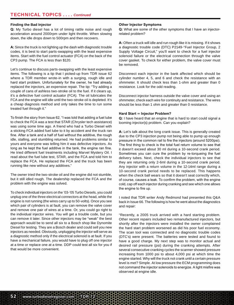
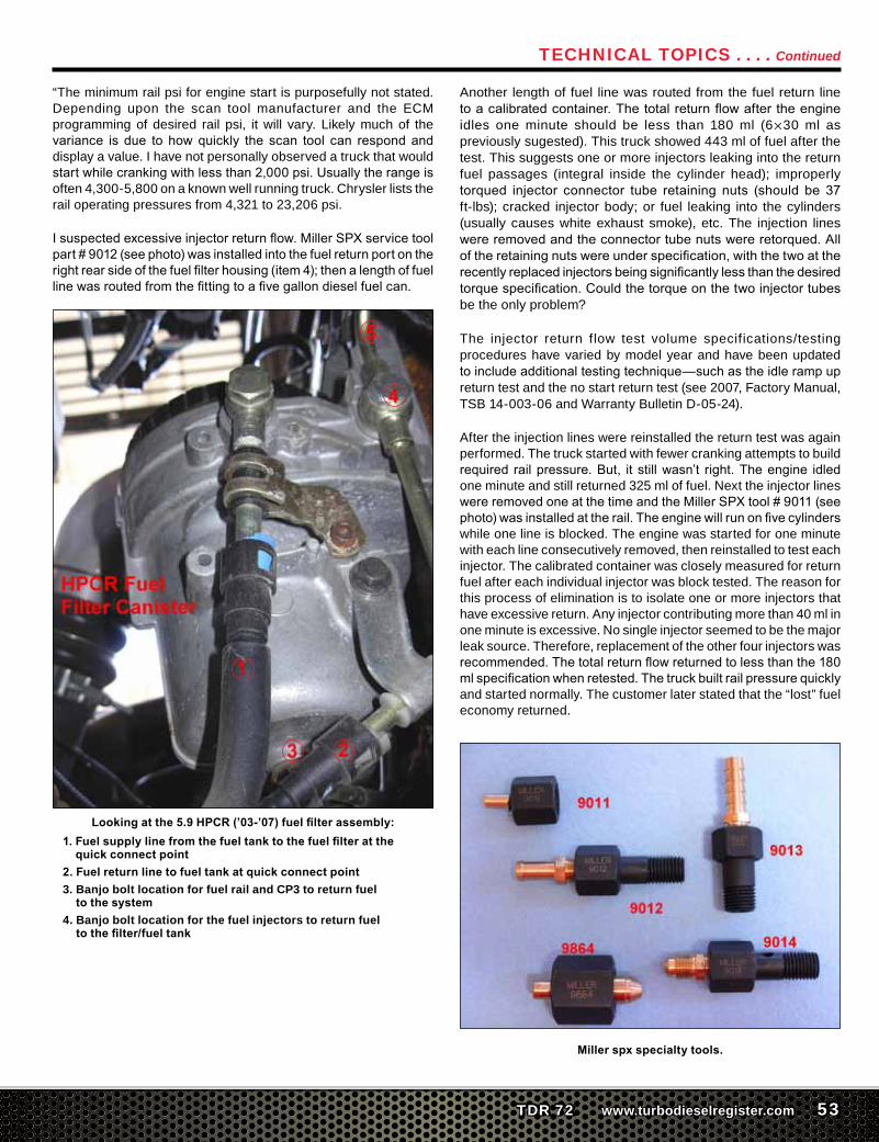
Isuspectedexcessiveinjectorreturnflow.MillerSPXservicetoolpart#9012(seephoto)wasinstalledintothefuelreturnportontherightrearsideofthefuelfilterhousing(item4);thenalengthoffuellinewasroutedfromthefittingtoafivegallondieselfuelcan.
Looking at the 5.9 HPCR (’03-’07) fuel filter assembly:1. Fuel supply line from the fuel tank to the fuel filter at the
quick connect point2. Fuel return line to fuel tank at quick connect point3. Banjo bolt location for fuel rail and CP3 to return fuel
to the system4. Banjo bolt location for the fuel injectors to return fuel
to the filter/fuel tank
Another length of fuel line was routed from the fuel return line toacalibratedcontainer.Thetotalreturnflowaftertheengineidles one minute should be less than 180 ml (6×30 ml as previously sugested). This truck showed 443 ml of fuel after the test. This suggests one or more injectors leaking into the return fuel passages (integral inside the cylinder head); improperly torqued injector connector tube retaining nuts (should be 37ft-lbs); cracked injector body; or fuel leaking into the cylinders (usually causes white exhaust smoke), etc. The injection lines wereremovedandtheconnectortubenutswereretorqued.Alloftheretainingnutswereunderspecification,withthetwoattherecentlyreplacedinjectorsbeingsignificantlylessthanthedesiredtorquespecification.Couldthetorqueonthetwoinjectortubesbe the only problem?
The injector return flow test volume specifications/testing procedures have varied by model year and have been updated toincludeadditionaltestingtechnique—suchastheidlerampupreturn test and the no start return test (see 2007, Factory Manual, TSB 14-003-06 and Warranty Bulletin D-05-24).
After the injection lines were reinstalled the return test was again performed. The truck started with fewer cranking attempts to build required railpressure.But, itstillwasn’t right.Theengine idledone minute and still returned 325 ml of fuel. Next the injector lines wereremovedoneatthetimeandtheMillerSPXtool#9011(seephoto)wasinstalledattherail.Theenginewillrunonfivecylinderswhile one line is blocked. The engine was started for one minute with each line consecutively removed, then reinstalled to test each injector. The calibrated container was closely measured for return fuel after each individual injector was block tested. The reason for this process of elimination is to isolate one or more injectors that have excessive return. Any injector contributing more than 40 ml in one minute is excessive. No single injector seemed to be the major leak source. Therefore, replacement of the other four injectors was recommended.Thetotalreturnflowreturnedtolessthanthe180mlspecificationwhenretested.Thetruckbuiltrailpressurequicklyand started normally. The customer later stated that the “lost” fuel economy returned.
Miller spx specialty tools.
Technical Topics . . . . Continued
54 www.turbodieselregister.com TDR 72
When to Replace Injectors?Q: My 2004 Turbo Diesel has 198,000 miles, but so far no injector problems. Should I replace the injectors now, or wait until I have a problem? They are expensive.
A: Perhaps some discussion about modes of failure would be in orderhere.Assomefeel,ifthingsarefine,youdon’tneedtochangeinjectors. If you haven’t added power, the mechanical aspects will be fineforalongtime.AsImentioned,highexhaustgastemperaturesandhighrailpressurescancausedamage.Cracksinthenozzlesor bodies, and wear of the check ball and seat are two problems that can occur. On the other hand, failure of the electrical solenoid can happen any time.
Whether you want to incur cost now is up to you. I have heard of folks paying more for reconditioned injectors than what new ones can be bought for. I have heard of high costs at some shops for replacement, and have seen evidence of poor workmanship, leading to further problems. Therefore, you may have two reasons for performing preventive maintenance. You can choose the mechanic/shop and you can buy the latest, stainless steel injectors. On the other hand, you might be able to continue using your old parts for many more miles. Consider also your usage for the truck. If you take long trips through unpopulated areas, such as in the West, a failure could leave you stranded.
What Does it Cost?Q: Okay, let’s get to the bottom-line: what is it going to cost to replace the injectors, and can I replace them as needed?
A:Inthe“InjectorUpgradesandPreventingFailures”sectionofthisarticleIbrieflytouchedonthecost,butletmetakethisopportunitytobespecific.
For thedo-it-yourselfer thefirst timeyou removeand installaninjector(s)cantakeafull8-hourday.SubsequentR&Icanbedonein about 4-5 hours. So, time is money…what is the cost of shop labor in your area? What is your time worth?
Unfortunatelyittakesalmostaslongtochangeonlyoneinjectorasit does to do all six. All types of intake plumbing, breather assembly, wiring, and injector lines have to be removed. So, outside of a low mileage, one-off kind of situation, or where you have a DTC telling you what to do, if an injector is giving problems and you’ve had a good service life from Day One, I would replace all six injectors at the same time.
Shopsandvendorshavebeeninvestingsix-figuresumsofmoneyto be able to test injectors. Should you have the time to send out for test, this service is becoming more so available. Injector testing cost about $50-60 per unit.
What about the cost of the replacement injectors?
The editor recently did a search using different engine serial numbers used in years 2003-2009 engines. Interestingly there are only three injector generations. I’ll break those down, along with part numbers, for you:
Bosch Cummins ReCon Mopar’03-’04 X0986435503 5254686RX R 8004082AB’04.5-’07 X0986435505 5254688RX R 5135790AE’07.5-current X0986435518 5253220NX R 8069384AA
How much do the injectors cost? On any given day you can search theinternetandgetpricequotesfrom$300toover$700perinjector.Onanygivendayyoucanbebumfuzzledwithhypeandsuchbyalligator-this and hot rod-that shops that claim to sell injectors. On anygivendaythereisashoporvendorthathasinvestedsix-figuresumsofmoneyforBoschteststandequipmenttocheck,testandremanufacture these injectors. On any given day there may be a short supply of injector units.
If you need injectors you’ll want to deal with reputable sales agents. For your consideration: Mopar, Cummins, Cummins ReCon, Bosch accredited shops as recognized by theAssociation ofDiesel Specialist (www.diesel.org, page 137, TDR vendors and specialty shops.
Did you want a performance upgrade injector with your order, sir? How about an order of fries or a hot apple pie? (My attempt at being cute…)
So, as I mentioned before, the average price for a six-pack of injectors and
their removal and replacement: $2000-$3000 for parts, 8 hours for labor.
Stock or Aftermarket InjectorsQ: What is better, stock or aftermarket injectors to replace my leaking injectors? Can I replace them myself?
A:DynomiteDieselhastheBoschinjectortestingequipmentandgets the new stainless steel bodies when they get new injectors from Bosch. They recommend the Stage 1 over stock for performance and mileage. That is what I put into my Turbo Diesel recently. They provide complete installation instructions with color photos with their injectors. For the “how to” on injector replacement, I’ve updated the instructionsthatIwrotefive-yearsagoinIssue51attheendofthisarticle. Be sure the seating nipple end of the connecting tubes are smooth and are seated uniformly, and that the injector line ends are also smooth and corrosion free.
For further discussion on the Dynomite Diesel injectors you’ll want to reread the detailed articles in Issue 66, page 46; Issue 60, page 84; Issue 59, page 86; Issue 57, page 45; Issue 56, page 96.
Technical Topics . . . . Continued

56 www.turbodieselregister.com TDR 72
Injector Removal and Replacement
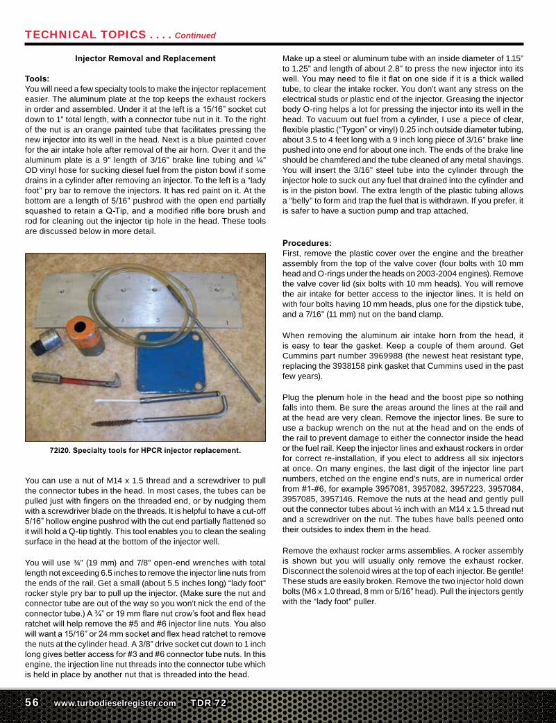
Tools:You will need a few specialty tools to make the injector replacement easier. The aluminum plate at the top keeps the exhaust rockers inorderandassembled.Underitattheleftisa15/16”socketcutdown to 1” total length, with a connector tube nut in it. To the right of the nut is an orange painted tube that facilitates pressing the new injector into its well in the head. Next is a blue painted cover for the air intake hole after removal of the air horn. Over it and the aluminum plate is a 9” length of 3/16” brake line tubing and ¼” OD vinyl hose for sucking diesel fuel from the piston bowl if some drains in a cylinder after removing an injector. To the left is a “lady foot” pry bar to remove the injectors. It has red paint on it. At the bottom are a length of 5/16” pushrod with the open end partially squashedtoretainaQ-Tip,andamodifiedrifleborebrushandrod for cleaning out the injector tip hole in the head. These tools are discussed below in more detail.
72i20. Specialty tools for HPCR injector replacement.
You can use a nut of M14 x 1.5 thread and a screwdriver to pull the connector tubes in the head. In most cases, the tubes can be pulledjustwithfingersonthethreadedend,orbynudgingthemwith a screwdriver blade on the threads. It is helpful to have a cut-off 5/16”hollowenginepushrodwiththecutendpartiallyflattenedsoit will hold a Q-tip tightly. This tool enables you to clean the sealing surface in the head at the bottom of the injector well.
You will use ¾” (19 mm) and 7/8” open-end wrenches with total length not exceeding 6.5 inches to remove the injector line nuts from the ends of the rail. Get a small (about 5.5 inches long) “lady foot” rocker style pry bar to pull up the injector. (Make sure the nut and connector tube are out of the way so you won’t nick the end of the connectortube.)A¾”or19mmflarenutcrow’sfootandflexheadratchetwillhelpremovethe#5and#6injectorlinenuts.Youalsowillwanta15/16”or24mmsocketandflexheadratchettoremovethe nuts at the cylinder head. A 3/8” drive socket cut down to 1 inch longgivesbetteraccessfor#3and#6connectortubenuts.Inthisengine, the injection line nut threads into the connector tube which is held in place by another nut that is threaded into the head.
Make up a steel or aluminum tube with an inside diameter of 1.15” to 1.25” and length of about 2.8” to press the new injector into its well.Youmayneedtofileitflatononesideifitisathickwalledtube, to clear the intake rocker. You don’t want any stress on the electrical studs or plastic end of the injector. Greasing the injector body O-ring helps a lot for pressing the injector into its well in the head. To vacuum out fuel from a cylinder, I use a piece of clear, flexibleplastic(“Tygon”orvinyl)0.25inchoutsidediametertubing,about 3.5 to 4 feet long with a 9 inch long piece of 3/16” brake line pushed into one end for about one inch. The ends of the brake line should be chamfered and the tube cleaned of any metal shavings. You will insert the 3/16” steel tube into the cylinder through the injector hole to suck out any fuel that drained into the cylinder and is in the piston bowl. The extra length of the plastic tubing allows a “belly” to form and trap the fuel that is withdrawn. If you prefer, it is safer to have a suction pump and trap attached.
Procedures:First, remove the plastic cover over the engine and the breather assembly from the top of the valve cover (four bolts with 10 mm head and O-rings under the heads on 2003-2004 engines). Remove the valve cover lid (six bolts with 10 mm heads). You will remove the air intake for better access to the injector lines. It is held on with four bolts having 10 mm heads, plus one for the dipstick tube, and a 7/16” (11 mm) nut on the band clamp.
When removing the aluminum air intake horn from the head, it is easy to tear thegasket.Keepacoupleof themaround.GetCummins part number 3969988 (the newest heat resistant type, replacing the 3938158 pink gasket that Cummins used in the past few years).
Plug the plenum hole in the head and the boost pipe so nothing falls into them. Be sure the areas around the lines at the rail and at the head are very clean. Remove the injector lines. Be sure to use a backup wrench on the nut at the head and on the ends of the rail to prevent damage to either the connector inside the head orthefuelrail.Keeptheinjectorlinesandexhaustrockersinorderfor correct re-installation, if you elect to address all six injectors at once. On many engines, the last digit of the injector line part numbers, etched on the engine end’s nuts, are in numerical order from#1-#6,forexample3957081,3957082,3957223,3957084,3957085, 3957146. Remove the nuts at the head and gently pull out the connector tubes about ½ inch with an M14 x 1.5 thread nut and a screwdriver on the nut. The tubes have balls peened onto their outsides to index them in the head.
Remove the exhaust rocker arms assemblies. A rocker assembly is shown but you will usually only remove the exhaust rocker. Disconnect the solenoid wires at the top of each injector. Be gentle! These studs are easily broken. Remove the two injector hold down bolts (M6 x 1.0 thread, 8 mm or 5/16” head). Pull the injectors gently with the “lady foot” puller.
Technical Topics . . . . Continued
TDR 72 www.turbodieselregister.com 57
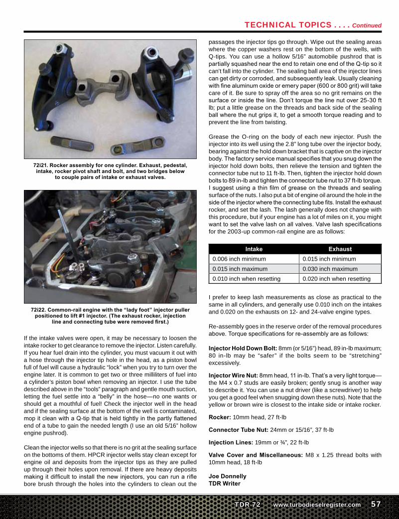
72i21. Rocker assembly for one cylinder. Exhaust, pedestal, intake, rocker pivot shaft and bolt, and two bridges below
to couple pairs of intake or exhaust valves.
72i22. Common-rail engine with the “lady foot” injector puller positioned to lift #1 injector. (The exhaust rocker, injection
line and connecting tube were removed first.)
If the intake valves were open, it may be necessary to loosen the intake rocker to get clearance to remove the injector. Listen carefully. If you hear fuel drain into the cylinder, you must vacuum it out with a hose through the injector tip hole in the head, as a piston bowl full of fuel will cause a hydraulic “lock” when you try to turn over the engine later. It is common to get two or three milliliters of fuel into a cylinder’s piston bowl when removing an injector. I use the tube described above in the “tools” paragraph and gentle mouth suction, letting the fuel settle into a “belly” in the hose—no one wants or should get a mouthful of fuel! Check the injector well in the head and if the sealing surface at the bottom of the well is contaminated, mopitcleanwithaQ-tipthatisheldtightlyinthepartlyflattenedend of a tube to gain the needed length (I use an old 5/16” hollow engine pushrod).
Clean the injector wells so that there is no grit at the sealing surface on the bottoms of them. HPCR injector wells stay clean except for engine oil and deposits from the injector tips as they are pulled up through their holes upon removal. If there are heavy deposits makingitdifficulttoinstall thenewinjectors,youcanrunariflebore brush through the holes into the cylinders to clean out the
passages the injector tips go through. Wipe out the sealing areas where the copper washers rest on the bottom of the wells, with Q-tips. You can use a hollow 5/16” automobile pushrod that is partiallysquashedneartheendtoretainoneendoftheQ-tipsoitcan’t fall into the cylinder. The sealing ball area of the injector lines cangetdirtyorcorroded,andsubsequentlyleak.Usuallycleaningwithfinealuminumoxideoremerypaper(600or800grit)willtakecare of it. Be sure to spray off the area so no grit remains on the surfaceorinsidetheline.Don’ttorquethelinenutover25-30ftlb; put a little grease on the threads and back side of the sealing ballwherethenutgripsit,togetasmoothtorquereadingandtoprevent the line from twisting.
Grease the O-ring on the body of each new injector. Push the injector into its well using the 2.8” long tube over the injector body, bearing against the hold down bracket that is captive on the injector body.Thefactoryservicemanualspecifiesthatyousnugdowntheinjector hold down bolts, then relieve the tension and tighten the connector tube nut to 11 ft-lb. Then, tighten the injector hold down boltsto89in-lbandtightentheconnectortubenutto37ft-lbtorque.Isuggestusingathinfilmofgreaseonthethreadsandsealingsurface of the nuts. I also put a bit of engine oil around the hole in the sideoftheinjectorwheretheconnectingtubefits.Installtheexhaustrocker, and set the lash. The lash generally does not change with this procedure, but if your engine has a lot of miles on it, you might wanttosetthevalvelashonallvalves.Valvelashspecificationsfor the 2003-up common-rail engine are as follows:
Intake Exhaust0.006 inch minimum 0.015 inch minimum
0.015 inch maximum 0.030 inch maximum0.010 inch when resetting 0.020 inch when resetting
I prefer to keep lash measurements as close as practical to the same in all cylinders, and generally use 0.010 inch on the intakes and 0.020 on the exhausts on 12- and 24-valve engine types.
Re-assembly goes in the reserve order of the removal procedures above.Torquespecificationsforre-assemblyareasfollows:
Injector Hold Down Bolt: 8mm (or 5/16”) head, 89 in-lb maximum; 80 in-lb may be “safer” if the bolts seem to be “stretching” excessively.
Injector Wire Nut:8mmhead,11in-lb.That’saverylighttorque—the M4 x 0.7 studs are easily broken; gently snug is another way to describe it. You can use a nut driver (like a screwdriver) to help you get a good feel when snugging down these nuts). Note that the yellow or brown wire is closest to the intake side or intake rocker.
Rocker: 10mm head, 27 ft-lb
Connector Tube Nut: 24mm or 15/16”, 37 ft-lb
Injection Lines: 19mm or ¾”, 22 ft-lb
Valve Cover and Miscellaneous: M8 x 1.25 thread bolts with 10mm head, 18 ft-lb
Joe DonnellyTDR Writer
Technical Topics . . . . Continued