Embed Size (px)
Citation preview
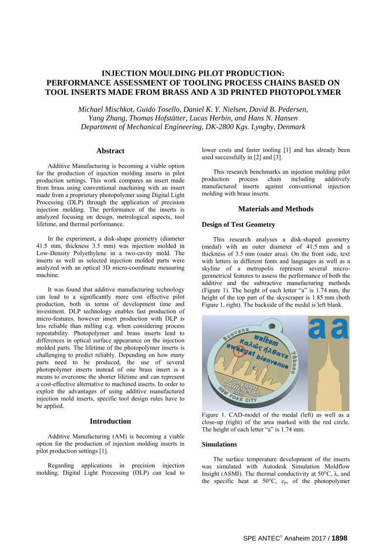
INJECTION MOULDING PILOT PRODUCTION: PERFORMANCE ASSESSMENT OF TOOLING PROCESS CHAINS BASED ON TOOL INSERTS MADE FROM BRASS AND A 3D PRINTED PHOTOPOLYMER
Michael Mischkot, Guido Tosello, Daniel K. Y. Nielsen, David B. Pedersen,
Yang Zhang, Thomas Hofstätter, Lucas Herbin, and Hans N. Hansen Department of Mechanical Engineering, DK-2800 Kgs. Lyngby, Denmark
Abstract
Additive Manufacturing is becoming a viable option for the production of injection molding inserts in pilot production settings. This work compares an insert made from brass using conventional machining with an insert made from a proprietary photopolymer using Digital Light Processing (DLP) through the application of precision injection molding. The performance of the inserts is analyzed focusing on design, metrological aspects, tool lifetime, and thermal performance.
In the experiment, a disk-shape geometry (diameter
41.5 mm, thickness 3.5 mm) was injection molded in Low-Density Polyethylene in a two-cavity mold. The inserts as well as selected injection molded parts were analyzed with an optical 3D micro-coordinate measuring machine.
It was found that additive manufacturing technology
can lead to a significantly more cost effective pilot production, both in terms of development time and investment. DLP technology enables fast production of micro-features, however insert production with DLP is less reliable than milling e.g. when considering process repeatability. Photopolymer and brass inserts lead to differences in optical surface appearance on the injection molded parts. The lifetime of the photopolymer inserts is challenging to predict reliably. Depending on how many parts need to be produced, the use of several photopolymer inserts instead of one brass insert is a means to overcome the shorter lifetime and can represent a cost-effective alternative to machined inserts. In order to exploit the advantages of using additive manufactured injection mold inserts, specific tool design rules have to be applied.
Introduction
Additive Manufacturing (AM) is becoming a viable option for the production of injection molding inserts in pilot production settings [1].
Regarding applications in precision injection
molding, Digital Light Processing (DLP) can lead to
lower costs and faster tooling [1] and has already been used successfully in [2] and [3].
This research benchmarks an injection molding pilot
production process chain including additively manufactured inserts against conventional injection molding with brass inserts.
Materials and Methods
Design of Test Geometry
This research analyses a disk-shaped geometry
(medal) with an outer diameter of 41.5 mm and a thickness of 3.5 mm (outer area). On the front side, text with letters in different fonts and languages as well as a skyline of a metropolis represent several micro-geometrical features to assess the performance of both the additive and the subtractive manufacturing methods (Figure 1). The height of each letter “a” is 1.74 mm, the height of the top part of the skyscraper is 1.85 mm (both Figure 1, right). The backside of the medal is left blank.
Figure 1. CAD-model of the medal (left) as well as a close-up (right) of the area marked with the red circle. The height of each letter “a” is 1.74 mm.
Simulations
The surface temperature development of the inserts
was simulated with Autodesk Simulation Moldflow Insight (ASMI). The thermal conductivity at 50°C, λ, and the specific heat at 50°C, cp, of the photopolymer
SPE ANTEC® Anaheim 2017 / 1898
employed for the additive manufacturing of the inserts (see Tooling) were calculated as λ = 0.1836 W/mK and cp = 2080 J/kgK, based on [4].
The surface temperature of the insert was measured at the end of an injection molding cycle with an infrared thermometer. Tooling
The inserts were printed in a photopolymer material
(HTM140V2) with a printer using DLP technology from Envisiontec. The post-production process is essential for a successful realisation of fine details. A liquid photopolymer that remains attached to the printed part can be cured by ambient light. Therefore, thorough cleaning in isopropanol and with pressurized air has to be performed manually, which introduces a human uncertainty factor.
Injection Molding
The injection molding was performed in Low-Density
Polyethylene (LDPE) with an ENGEL e-motion 170/110 injection molding machine. The inserts were mounted with a pressure measurement foil between the mold block and the inserts in order to detect potential pressure peaks (e.g. due to insert warpage) and to soften them. Eight pairs of DLP inserts were tested in a two-level three-factor full-factorial design of experiments (DOE) for a total of 23 = 8 different process combinations (Table 1). First, 25 shots were performed with each pair of inserts (mounted on the movable and fixed part of the mold, respectively). Afterwards, all pairs were used for part production until disintegration. Table 1. Low and high levels of the three injection molding control factors.
Low (-) High (+)
Cooling temperature (Tcool)
21°C 35°C Injection speed (vinj) 15 mm/s 30 mm/s
Packing pressure (ppack) 100 bar 150 bar
Additionally, a pair of brass inserts was used as a reference (Figure 2, left). Metrological Assessment
The printing quality was assessed with a coordinate
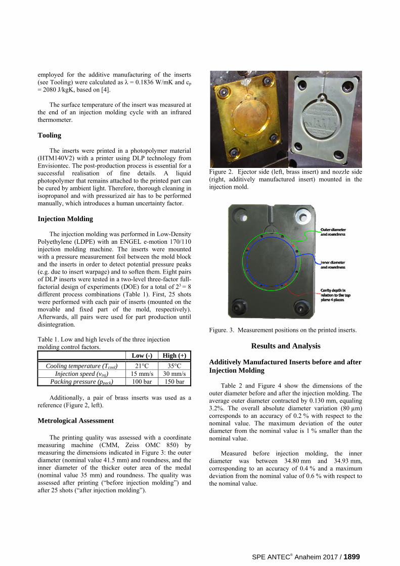
measuring machine (CMM, Zeiss OMC 850) by measuring the dimensions indicated in Figure 3: the outer diameter (nominal value 41.5 mm) and roundness, and the inner diameter of the thicker outer area of the medal (nominal value 35 mm) and roundness. The quality was assessed after printing (“before injection molding”) and after 25 shots (“after injection molding”).
Figure 2. Ejector side (left, brass insert) and nozzle side (right, additively manufactured insert) mounted in the injection mold.
Figure. 3. Measurement positions on the printed inserts.
Results and Analysis
Additively Manufactured Inserts before and after Injection Molding
Table 2 and Figure 4 show the dimensions of the outer diameter before and after the injection molding. The average outer diameter contracted by 0.130 mm, equaling 3.2%. The overall absolute diameter variation (80 µm) corresponds to an accuracy of 0.2 % with respect to the nominal value. The maximum deviation of the outer diameter from the nominal value is 1 % smaller than the nominal value.
Measured before injection molding, the inner
diameter was between 34.80 mm and 34.93 mm, corresponding to an accuracy of 0.4 % and a maximum deviation from the nominal value of 0.6 % with respect to the nominal value.
SPE ANTEC® Anaheim 2017 / 1899
After injection molding, the inner diameter had decreased as well and was measured to be between 34.66 mm and 34.83 mm.
Table 2. Minimum, maximum, average, and standard deviation of the outer diameter before and after injection molding (in mm).
Min Max Avg Std
Before IM 41.070 41.148 41.121 0.022
After IM 41.055 40.932 40.992 0.034
Figure 4. Outer diameter (in mm) of the eight inserts used on the ejector side before (left columns) and after (right columns) injection molding.
The roundness was assessed using the Minimum
Zone circle (MZC) definition. Table 3 and Figure 5 show that the average roundness of the outer diameter increases by 0.00246 mm, equaling 3.7%.
Table 3. Minimum, maximum, average, and standard deviation of the roundness error of the outer diameter before and after injection molding (in mm).
Min Max Avg Std
Before IM 0.050 0.080 0.067 0.009
After IM 0.054 0.083 0.069 0.008
Figure 5. Roundness error (in mm) of the eight inserts before (left) and after (right) injection molding.
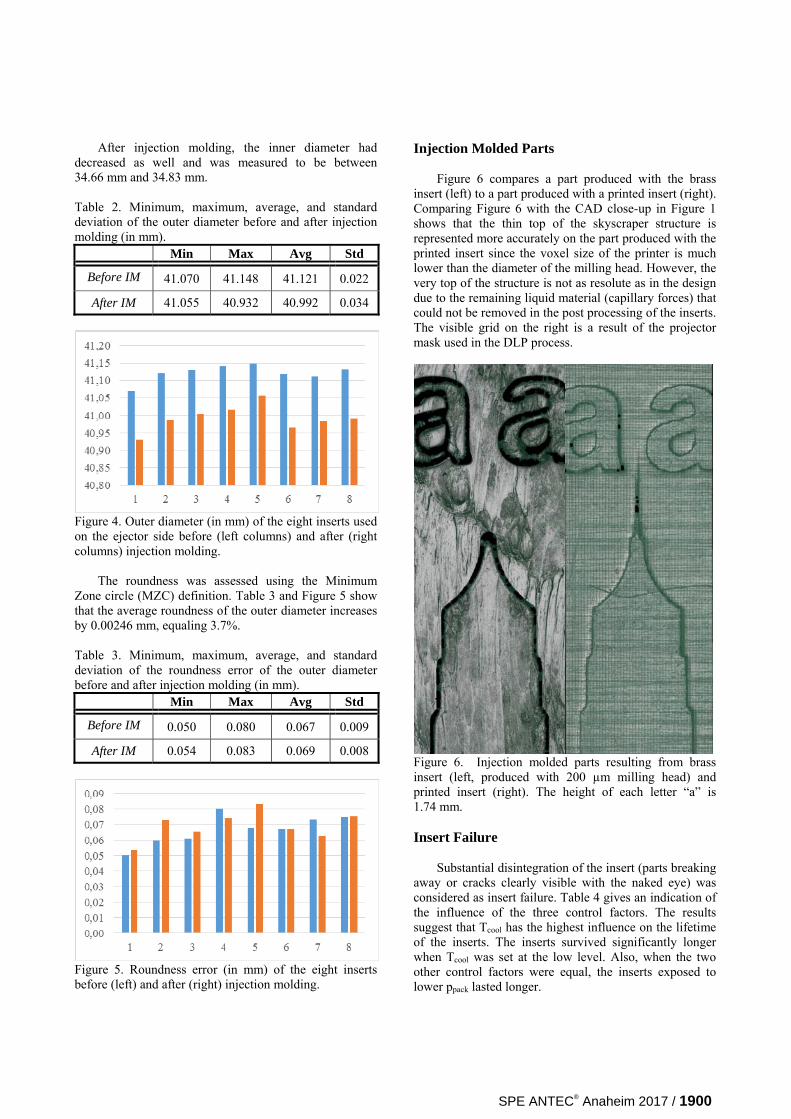
Injection Molded Parts Figure 6 compares a part produced with the brass
insert (left) to a part produced with a printed insert (right). Comparing Figure 6 with the CAD close-up in Figure 1 shows that the thin top of the skyscraper structure is represented more accurately on the part produced with the printed insert since the voxel size of the printer is much lower than the diameter of the milling head. However, the very top of the structure is not as resolute as in the design due to the remaining liquid material (capillary forces) that could not be removed in the post processing of the inserts. The visible grid on the right is a result of the projector mask used in the DLP process.
Figure 6. Injection molded parts resulting from brass insert (left, produced with 200 µm milling head) and printed insert (right). The height of each letter “a” is 1.74 mm. Insert Failure
Substantial disintegration of the insert (parts breaking away or cracks clearly visible with the naked eye) was considered as insert failure. Table 4 gives an indication of the influence of the three control factors. The results suggest that Tcool has the highest influence on the lifetime of the inserts. The inserts survived significantly longer when Tcool was set at the low level. Also, when the two other control factors were equal, the inserts exposed to lower ppack lasted longer.
SPE ANTEC® Anaheim 2017 / 1900
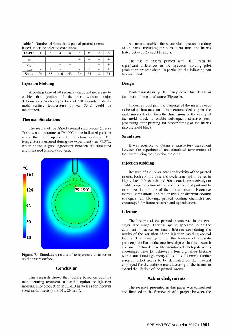
Table 4. Number of shots that a pair of printed inserts lasted under the selected conditions.
Insert 1 2 3 4 5 6 7 8
Tcool - - - - + + + + vinj - - + + - - + +
ppack - + - + - + - + Shots 91 63 116 43 26 25 32 31
Injection Molding
A cooling time of 50 seconds was found necessary to enable the ejection of the part without major deformations. With a cycle time of 300 seconds, a steady mold surface temperature of ca. 35°C could be maintained. Thermal Simulations
The results of the ASMI thermal simulations (Figure
7) show a temperature of 79.19°C at the indicated position when the mold opens after injection molding. The temperature measured during the experiment was 77.3°C, which shows a good agreement between the simulated and measured temperature value.
Figure. 7. Simulation results of temperature distribution on the insert surface
Conclusion
This research shows that tooling based on additive
manufacturing represents a feasible option for injection molding pilot production in PE-LD as well as for medium sized mold inserts (80 x 60 x 20 mm3).
All inserts enabled the successful injection molding of 25 parts. Including the subsequent runs, the inserts lasted between 25 and 116 shots.
The use of inserts printed with DLP leads to
significant differences in the injection molding pilot production process chain. In particular, the following can be concluded:
Design
Printed inserts using DLP can produce fine details in
the micro-dimensional range (Figure 6). Undesired post-printing warpage of the inserts needs
to be taken into account. It is recommended to print the mold inserts thicker than the dimensions of the cavity of the mold block to enable subsequent abrasive post-processing after printing for proper fitting of the inserts into the mold block.
Simulation
It was possible to obtain a satisfactory agreement
between the experimental and simulated temperature of the insert during the injection molding.
Injection Molding
Because of the lower heat conductivity of the printed
inserts, both cooling time and cycle time had to be set to high values (50 seconds and 300 seconds, respectively) to enable proper ejection of the injection molded part and to maximize the lifetime of the printed inserts. Extensive thermal simulations and the analysis of different cooling strategies (air blowing, printed cooling channels) are encouraged for future research and optimization.
Lifetime
The lifetime of the printed inserts was in the two-
digits shot range. Thermal ageing appeared to be the dominant influence on insert lifetime considering the results of the variation of the injection molding control factors. The investigation of the lifetime of a cavity geometry similar to the one investigated in this research and manufactured in a fiber-reinforced photopolymer is encouraged since [5] achieved a four digit shots lifetime with a small mold geometry (20 x 20 x 2.7 mm3). Further research effort needs to be dedicated on the material employed for the additive manufacturing of the inserts to extend the lifetime of the printed inserts.
Acknowledgements
The research presented in this paper was carried out
and financed in the framework of a project between the
SPE ANTEC® Anaheim 2017 / 1901

Technical University of Denmark (DTU) and the Manufacturing Academy of Denmark (MADE), (http://en.made.dk). Funding from Innovation Fund Denmark (http://innovationsfonden.dk/en) is greatly acknowledged.
References
1. I. Gibson et al., Additive Manufacturing
Technologies – 3D Printing, Rapid Prototyping and Direct Digital Manufacturing, Second edition 2015, Springer, New York, ISBN 978-1-4939-2112-6, p. 437ff.
2. P. M. Hackney, An Investigation into the Characteristics of Materials and Processes, for the Production of Accurate Direct Parts and Tools using 3D Rapid Prototyping Technologies, PhD thesis, Northumbria University, School of Computing Engineering and Information Sciences, 2007.
3. M. Mischkot et al., Additive manufacturing for the production of inserts for micro injection moulding, Proceedings of Euspen’s 15th International Conference & Exhibition, 2015.
4. Kovacs et al., Evaluation of measured and calculated thermal parameters of a photopolymer, International Communications in Heat and Mass Transfer 38 (2011) 863-867.
5. T. Hofstätter et al., Evolution of Surface Texture and Cracks During Injection Molding of Fiber-Reinforced, Additively-Manufactured, Injection Molding Inserts, Summer Topical Meeting, ASPE, 2016.
SPE ANTEC® Anaheim 2017 / 1902