Embed Size (px)
Citation preview

5/14/2018 Injection Molding Design - slidepdf.com
http://slidepdf.com/reader/full/injection-molding-design 1/17
Injection Molding Design Guidelines(Courtesy www.efunda.com)
Much has been written regarding design guidelines for injection molding. Yet, the design guidelinescan be summed up in just a few design rules.
1. Use uniform wall thicknesses throughout the part. This will minimize sinking, warping,
residual stresses, and improve mold fill and cycle times.
i. Wall Section Considerationsii. Voids and Shrinkageiii. Warpage
i. Uniform Walls (Wall Section Considerations)• Parts should be designed with a minimum wall thickness consistent with part function and
mold filling considerations. The thinner the wall the faster the part cools, and the cycle timesare short, resulting in the lowest possible part costs.Also, thinner parts weight less, which results in smaller amounts of the plastic used per partwhich also results in lower part costs.
• The wall thicknesses of an injection-molded part generally range from 2 mm to 4 mm (0.080inch to 0.160 inch). Thin wall injection molding can produce walls as thin as 0.5 mm (0.020inch).
The need for uniform walls • Thick sections cool slower than thin sections. The thin section first solidifies, and the thick
section is still not fully solidified. As the thick section cools, it shrinks and the material for theshrinkage comes only from the unsolidified areas, which are connected, to the alreadysolidified thin section.
• This builds stresses near the boundary of the thin section to thick section. Since the thinsection does not yield because it is solid, the thick section (which is still liquid) must yield.
Often this leads to warping or twisting. If this is severe enough, the part could even crack.
Uniform wall thicknesses reduce/eliminate this problem.• Uniform walled parts are easier to fill in the mold cavity, since the molten plastic does not face
varying restrictions as it fills.
What if you cannot have uniform walls, (due to design limitations) ?• When uniform walls are not possible, then the change in section should be as gradual as
possible.

5/14/2018 Injection Molding Design - slidepdf.com
http://slidepdf.com/reader/full/injection-molding-design 2/17
Coring can help in making the wall sections uniform, and eliminate the problems associatedwith non-uniform walls.
Warping problems can be reduced by building supporting features such as gussets.
ii. Voids and Shrinkage
• Shrinkage is caused by intersecting walls of non-uniform wall thickness. Examples of theseare ribs, bosses, and other projections of the nominal wall. If these projections have greater wall thicknesses, they will solidify slower. The region where they are attached to the nominalwall will shrink along with the projection, resulting in a sink in the nominal wall.
• Shrink can be minimized by maintaining rib thicknesses to 50 to 60% of the walls they are
attached to.• Bosses located at corners can result in very thick walls causing sinks. Bosses can be isolated
using the techniques illustrated.

5/14/2018 Injection Molding Design - slidepdf.com
http://slidepdf.com/reader/full/injection-molding-design 3/17
iii. WarpageThick sections cool slower than thin sections. The thin section first solidifies, and the thick section is still not fully solidified. As the thick section cools, it shrinks and the material for theshrinkage comes only from the unsolidified areas, which are connected, to the alreadysolidified thin section.This builds stresses near the boundary of the thin section to thick section. Since the thin
section does not yield because it is solid, the thick section (which is still liquid) must yield.Often this leads to warping or twisting. If this is severe enough, the part could even crack.
Other causes:• Warping can also be caused due to non-uniform mold temperatures or cooling rates.• Non-uniform packing or pressure in the mold.• Alignment of polymer molecules and fiber reinforcing strands during the mold fill results in
preferential properties in the part.• Molding process conditions--too high a injection pressure or temperature or improper
temperature and cooling of the mold cavity. Generally, it is best to follow the resinmanufacturer's guidelines on process conditions and only vary conditions within the limits of the guidelines.It is not good practice to go beyond the pressure and temperature recommendations tocompensate for other defects in the mold. If runners need to be sized differently to allow for a
proper fill, or gate sizes that need to be changed, then those changes need to happen.Otherwise the finished parts will have too much built in stresses, could crack in service or warp-leading to more severe problems such as customer returns or field service issues.

5/14/2018 Injection Molding Design - slidepdf.com
http://slidepdf.com/reader/full/injection-molding-design 4/17
2. Use generous radius at all corners. The inside corner radius should be a minimum of onematerial thickness.
Radius Limitations
Radius • Sharp corners greatly increase the stress concentration. This high amount of stress
concentration can often lead to failure of plastic parts.
Sharp corners can come about in non-obvious places. Examples of this are a boss attached to asurface, or a strengthening rib. These corners need to be radiused just like all other corners.The stress concentration factor varies with radius, for a given thickness.
As can be seen from the above chart, the stress concentration factor is quite high for R/T
values less than 0.5. For values of R/T over 0.5 the stress concentration factor gets lower.The stress concentration factor is a multiplier factor, it increases the stress.Actual Stress = Stress Concentration Factor K x Stress CalculatedThis is why it is recommended that inside radiuses be a minimum of 1 x thickness.
• In addition to reducing stresses, fillet radiuses provide streamlined flow paths for the molten plastic resulting in easier fills.
• Typically, at corners, the inside radius is 0.5 x material thickness and the outside radius is 1.5x material thickness. A bigger radius should be used if part design will allow it.
3. Use the least thickness compliant with the process, material, or product design requirements.

5/14/2018 Injection Molding Design - slidepdf.com
http://slidepdf.com/reader/full/injection-molding-design 5/17
Using the least wall thickness for the process ensures rapid cooling, short cycle times, andminimum shot weight. All these result in the least possible part cost.
4. Design parts to facilitate easy withdrawal from the mold by providing draft (taper) in thedirection of mold opening or closing.
Draft and Texture
The reason for draft • Drafts (or taper) in a mold, facilitates part removal from the mold. The amount of draft angle
depends on the depth of the part in the mold, and its required end use function.
• The draft is in the offset angle in a direction parallel to the mold opening and closing.
• It is best to allow for as much draft as possible for easy release from the mold. As a nominal
recommendation, it is best to allow 1 to 2 degrees of draft, with an additional 1.5° min. per 0.025 mm (0.001 inch) depth of texture. See below.
• The mold parting line can be relocated to split the draft in order to minimize it. If no draft isacceptable due to design considerations, then a side-action mold (cam-actuated) may berequired at a greater expense in tooling.
Snap LatchesSnaps allow an easy method of assembly and disassembly of plastic parts. Snaps consist of acantilever beam with a bump that deflects and snaps into a groove or a slot in the mating part.

5/14/2018 Injection Molding Design - slidepdf.com
http://slidepdf.com/reader/full/injection-molding-design 6/17
Snaps can have a uniform cross-section or a tapered cross section (with decreasing sectionheight). The tapered cross-section results in a smaller strain compared to the uniform cross-section. Here we consider the general case of a beam tapering in both directions.
When Rh=1 and Rb=1 , the above formula does not apply, L'Hospital's rule applies and theformula is simplified to the following:

5/14/2018 Injection Molding Design - slidepdf.com
http://slidepdf.com/reader/full/injection-molding-design 7/17
The disassembly force is a function of the coefficient of friction, which ranges from 0.3 to 0.6for most plastics. The coefficient of friction also varies with the surface roughness. Therougher the surface, the higher the coefficient of friction.There is an angle at which the mating parts cannot be pulled apart. This is known as the self-locking angle. If the angle of the snap is less than this angle, then the assembly can bedisassembled by a certain force given by the above formula.
The self-locking anglea = tan-1(1/µ)where µ is the coefficient of friction which ranges from 0.3 to 0.6 for most plastics.
This computes to angles ranging from73° for low coefficient of friction plastics to 59° for high coefficient of friction plastics.
If this angle is exceeded then the snaps will not pull apart unless the snap beam is deflected bysome other means such as a release tool.
This property can be used to advantage depending on the objective of using the snaps. If thesnaps are to be used in the factory for assembly only (never to be disassembled by the enduser), then the ramp angle the self-locking angle should be exceeded. If the user is expected todisassemble (to change batteries in a toy for example), then the angle should not be exceeded.
Tooling for snaps is often expensive and long lead time due to
● The iterations required achieving the proper fit in terms of over travel. The amount of over travel is a design issue. This will control how easy it is to assemble, and how much the mated
parts can rattle in assembly. This rattle can be minimized by reducing the over travel or designing in a preload to use the plastic's elastic properties. However, plastics tend to creepunder load, so preloading is to be avoided unless there is no other option.
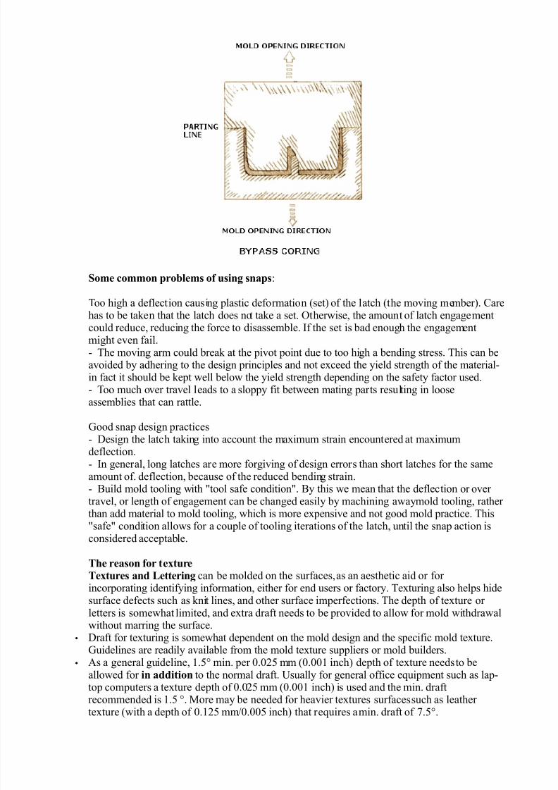
● Often, side action tooling (cam actuated) is required. This increases the mold costs and leadtimes. Cam actuated tooling can be avoided if bypass coring can be used that results in an
opening in the part to allow the coring to form the step.
5/14/2018 Injection Molding Design - slidepdf.com
http://slidepdf.com/reader/full/injection-molding-design 8/17
Some common problems of using snaps:
Too high a deflection causing plastic deformation (set) of the latch (the moving member). Carehas to be taken that the latch does not take a set. Otherwise, the amount of latch engagementcould reduce, reducing the force to disassemble. If the set is bad enough the engagementmight even fail.- The moving arm could break at the pivot point due to too high a bending stress. This can beavoided by adhering to the design principles and not exceed the yield strength of the material-in fact it should be kept well below the yield strength depending on the safety factor used.- Too much over travel leads to a sloppy fit between mating parts resulting in looseassemblies that can rattle.
Good snap design practices- Design the latch taking into account the maximum strain encountered at maximumdeflection.- In general, long latches are more forgiving of design errors than short latches for the sameamount of. deflection, because of the reduced bending strain.- Build mold tooling with "tool safe condition". By this we mean that the deflection or over travel, or length of engagement can be changed easily by machining awaymold tooling, rather than add material to mold tooling, which is more expensive and not good mold practice. This"safe" condition allows for a couple of tooling iterations of the latch, until the snap action isconsidered acceptable.
The reason for textureTextures and Lettering can be molded on the surfaces, as an aesthetic aid or for incorporating identifying information, either for end users or factory. Texturing also helps hidesurface defects such as knit lines, and other surface imperfections. The depth of texture or letters is somewhat limited, and extra draft needs to be provided to allow for mold withdrawalwithout marring the surface.
• Draft for texturing is somewhat dependent on the mold design and the specific mold texture.Guidelines are readily available from the mold texture suppliers or mold builders.
• As a general guideline, 1.5° min. per 0.025 mm (0.001 inch) depth of texture needsto beallowed for in addition to the normal draft. Usually for general office equipment such as lap-
top computers a texture depth of 0.025 mm (0.001 inch) is used and the min. draftrecommended is 1.5 °. More may be needed for heavier textures surfaces such as leather texture (with a depth of 0.125 mm/0.005 inch) that requires a min. draft of 7.5°.

5/14/2018 Injection Molding Design - slidepdf.com
http://slidepdf.com/reader/full/injection-molding-design 9/17
5. Use ribs or gussets to improve part stiffness in bending. This avoids the use of thick section toachieve the same, thereby saving on part weight, material costs, and cycle time costs.
Rib Design
The use of ribs• Ribs increase the bending stiffness of a part. Without ribs, the thickness has to be increased to
increase the bending stiffness. Adding ribs increases the moment of inertia, which increases
the bending stiffness. Bending stiffness = E (Young's Modulus) x I (Moment of Inertia)• The rib thickness should be less than the wall thickness-to keep sinking to a minimum. The
thickness ranges from 40 to 60 % of the material thickness. In addition, the rib should beattached to the base with generous radiusing at the corners.
• At rib intersections, the resulting thickness will be more than the thickness of each individualrib. Coring or some other means of removing material should be used to thin down the wallsto avoid excessive sinking on the opposite side.

5/14/2018 Injection Molding Design - slidepdf.com
http://slidepdf.com/reader/full/injection-molding-design 10/17
• The height of the rib should be limited to less than 3 x thickness. It is better to have multipleribs to increase the bending stiffness than one high rib.
• The rib orientation is based on providing maximum bending stiffness. Depending onorientation of the bending load, with respect to the part geometry, ribs oriented one wayincrease stiffness. If oriented the wrong way there is no increase in stiffness.
• Draft angles for ribs should be minimum of 0.25 to 0.5 degree of draft per side. If the surfaceis textured, additional 1.0 degree draft per 0.025 mm (0.001 inch) depth of texture should be
provided.

5/14/2018 Injection Molding Design - slidepdf.com
http://slidepdf.com/reader/full/injection-molding-design 11/17
Common Design Elements
(a) Rib(b) Boss(c) Counter bore/sink (d) Inserts(e) Self-Tapping Screws(f) Snap Latches
(g) Living Hinge
a) RibSee above
b) BossBoss DesignBosses are used for the purpose of registration of mating parts or for attaching fasteners such asscrews or accepting threaded inserts (molded-in, press-fitted, ultrasonically or thermally inserted).The wall thicknesses should be less than 60 % of nominal wall to minimize sinking. However, if the
boss is not in a visible area, then the wall thickness can be increased to allow for increased stressesimposed by self-tapping screws.
The base radius should be a minimum of 0.25 x thickness
The boss can be strengthened by gussets at the base, and by attaching it to nearby walls withconnecting ribs.

5/14/2018 Injection Molding Design - slidepdf.com
http://slidepdf.com/reader/full/injection-molding-design 12/17
Hoop stresses are imposed on the boss walls by press fitting or otherwise inserting inserts.
The maximum insertion (or withdrawal) force Fmaxand the maximum hoop stress, occurring at the
inner diameter of the boss, smax is given by

5/14/2018 Injection Molding Design - slidepdf.com
http://slidepdf.com/reader/full/injection-molding-design 13/17
Failures of a boss are usually attributable to:
• High hoop stresses caused because of too much interference of the internal diameter with theinsert (or screw).
• Knit lines -these are cold lines of flow meeting at the boss from opposite sides, causing weak bonds. These can split easily when stress is applied.
• Knit lines should be relocated away from the boss, if possible. If not possible, then a
supporting gusset should be added near the knit line.
c) Counter Bore/Sink
• Counter-sinking is often done to accommodate heads of flat head screws. However as can beseen from the figure, there is a sideways component of the thrust which could split thecountersink due to the generated hoop stresses
• Counter-boring is done to accommodate pan-head, fillister-head or round-head screws or other screws with flat-bottomed undersides

5/14/2018 Injection Molding Design - slidepdf.com
http://slidepdf.com/reader/full/injection-molding-design 14/17
• Counter-bored screws exert only force in the axial direction, thus operate mostly under compression, with no sideward component to the applied force vector. Such design isinherently more robust than counter-sinking.
d) InsertsInserts are used in plastic parts, to allow the use of fasteners such as machine screws. The
advantage of this is that since these inserts are made out of metal, they are robust. Further,machine threads also allow great many cycles of assembly and disassembly• Inserts are installed using one of the following methods:- Ultrasonic insertion. The insert is vibrated using an ultrasonic transducer, called the "horn"mounted in an ultrasonic machine.
The horn has to be specially designed for each application for optimum performance. Theultrasonic energy is converted to thermal energy due to the vibrating action, which allows theinsert to be melted inside the hole.This type of insertion can be done rapidly, with short cycle times, low residual stresses. Goodmelt flow characteristics for the plastic are necessary for the process to be successful.The ultrasonic equipment is relatively expensive, and also needs a custom horn for optimal
production rates.

5/14/2018 Injection Molding Design - slidepdf.com
http://slidepdf.com/reader/full/injection-molding-design 15/17
Thermal Insertion. The inserts are heated by placing them over the hole and pressing them in with aheated tool. The tool first heats the insert, then the insert is pressed in.
The advantage of this method is that the special tooling necessary is relatively simple, usually acylindrical tool, which can be easily, fabricated in the machine shop. The cycle times are usuallyshort.However, care has to be taken, not to overheat the insert or the plastic, or it will lead to local plasticdegradation.
Press Fitting. The inserts are designed with barbs (straight knurls that are interrupted) and can be press fitted inside the hole in the boss.This process is fast and requires no special tooling. However, high hoop stresses are generated, so the
boss design has to be robust. Also, the retention is strictly based on press fitting and the small amountof material that flows inside the barbs. Thus retention is not very high.Molded-in Inserts. The inserts are placed in the mold prior to the injection of plastic. The injection of the plastic completely encases the insert on the outer diameter and provides very good retention. Infact retention of such inserts is the best compared to other process (barb/knurl design being the same).This process slows down the operation of the mold, since the inserts have to be manually placedinside the mold. Inserts can be automatically placed in a mold, but this greatly increases thecomplexity and cost of the mold. This can only be justified if the volume of production is very high to
offset the cost savings in shorter cycle times.
e) Self-Tapping ScrewsSelf-tapping screws are often used to fasten plastic parts together. Self-tapping screws areavailable both in thread-cutting type as well as thread-forming type.
Thread Forming
Pros Cons
High tensile values High hoop stress, boss has to be designed to withstand this stress
High amount of torque to stripthreads
Large number of cycles of assembly and disassembly
possibleStress relaxation possible
Suitable for plastics that arenon-brittle
Not suitable for brittle plastics
Thread Cutting
Pros Cons
Lower Hoop Stress Lower Tensile Pullout
Suitable for brittle plastics Lower amount of torque to pull the threads

5/14/2018 Injection Molding Design - slidepdf.com
http://slidepdf.com/reader/full/injection-molding-design 16/17
f) Snap LatchesSee above
g) Living HingeLiving hinges are thin sections of plastic that connect two segments of a part to keep themtogether and allow the part to be opened and closed. Typically these are used in containers thatare used in high volume applications such as toolboxes, fish tackle boxes, CD boxes etc.
The materials used to make a living hinge are usually a very flexible plastic such as polypropylene and polyethylene. These can flex more than a million cycles without failure.
Besides meeting the design guidelines, the hinges have to be processed properly. The
molecules have to be oriented along the hinge line for the hinge to have acceptable life.As molded the fibers of the plastic are somewhat random in orientation. In order to orient thefibers to aid in prolonging the hinge life, some or all of the following practices should befollowed:
i. The gate location should be such as to allow the plastic to flow across the hinge for maximumstrength.
ii. As the part comes out of the mold, it needs to be flexed a minimum of 2 times while it is stillhot, for optimum strength
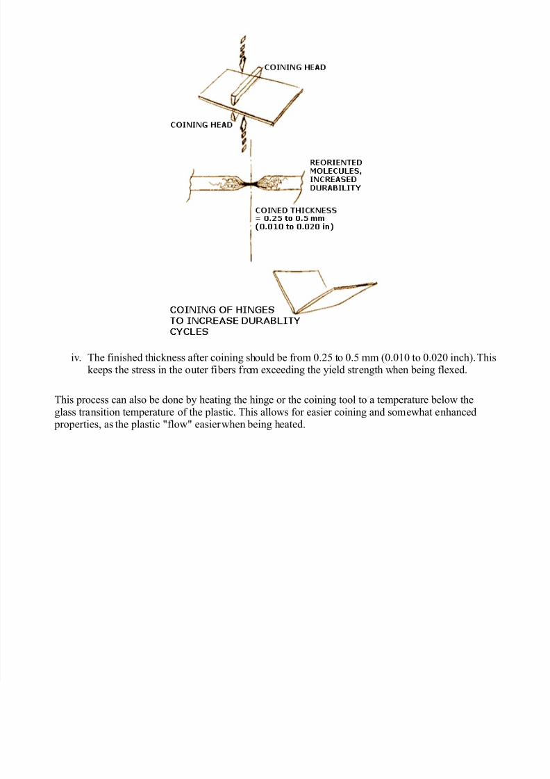
iii. Coining is often done to give the hinge, enhanced properties. The coining process compressesthe hinge to a pre-determined thickness. The strain induced is greater than the yield stress of
the plastic. This will plastically deform the hinge (i.e. place it outside the elastic range into the plastic range). The amount of coining (compression) should be less than the ultimate stress, tokeep the hinge from fracturing.
5/14/2018 Injection Molding Design - slidepdf.com
http://slidepdf.com/reader/full/injection-molding-design 17/17
iv. The finished thickness after coining should be from 0.25 to 0.5 mm (0.010 to 0.020 inch). Thiskeeps the stress in the outer fibers from exceeding the yield strength when being flexed.
This process can also be done by heating the hinge or the coining tool to a temperature below the
glass transition temperature of the plastic. This allows for easier coining and somewhat enhanced properties, as the plastic "flow" easier when being heated.