Embed Size (px)
Citation preview
Initialization file LTire.ini / LTireW.iniThe following setups are possible in the configuration file LTire.ini (LTire 5 and 6) / LTireW.ini (LTire 7):
[ProgramPar]
ZeitAnzeige=OnSwitches the time display in output dialog on/off.
SaveBackground=OnSwitches the storing of backgrounds of dialogs on/off. If very small main memory is available, this option should be switched off, because this function operates memory intensively.
Function method:
SaveBackground=On: After leaving a dialog the previously stored graphics of a dialog is drawn again. Advantage: Considerably faster screen-up time, especially when handling large quantities of data.Disadvantage: Greater memory requirement
SaveBackground=Off: After leaving a dialog the graphics are constructed anew.
OffsetDialog=OnSafety function.Switches the button for calling up the offset-dialog in the machine parameter- dialog on or off. If the button is switched off, an accidential changing of the offset values by the user is almost impossible. Wrong offset values are difficult to recognize at first sight, but they usually lead to completely wrong engraving results.
SPSServiceDialog=OffOnly LANG service technical engineers use this function !
Undo=2Determines the number of Undo steps. Here it is to note, that a large amount of Undo steps requirers a large amount of physical main memory. Undo-function
MarkLine=1Indicates the line thickness of the marked data in pixels. A line thickness of 2-3 pixel is suitable for representing marked data. For the edit functions, a line thickness of 1 pixel is suitable, because it is easier to recognize a contour with very thin lines. The following attitudes proved effective:machine-pc:MarkLine=3construction-pc:MarkLine=1
Edit=OnIt indicates whether the complete edit menu is active or inactive. The edit menu on the machine-pc should be inactivated, so that an unintentional changing of the data is prevented.machine-pc:Edit=Offconstruction-pc:Edit=On
[Werkzeugwechsler]
Note: Only one of the following three options may be selected.
WW=24-fach Trommelif 24 station drum changer and measuring system are installed.
WW=Messpunkt if no tool changer, but measuring system is available.
WW=Handif neither tool changer nor measuring point is available.
SPS=OnEnables the communication with the SPS controller if it is available. This is essential for the 24 station drum changer.
StreckeY=50Gives the distance of the Y-axis in [mm], which should be covered, when it is driven from the tool change position to the measuring point. If very long tools are used, 50[mm] can be too less. In this case collision could occur.
[MaschPar]
The following adjustments in the part [MaschPar] configures the machine. Except for the adjustment <Res> the values should not be changed by the user or machine operator.
1=Schr/Umdr Tisch :6400Gives the step resolution of the round table. This value should never be changed by the user or machine operator.
2=Gdr/Umdr Tisch :1.0Gives the step resolution of the round table. This value should never be changed by the user or machine operator.
3=GSW Motorfahren :127Gives the max. speed of the axis when operated manually. This value should only be changed, if offset problems occur in the machine setup menu while moving the axis manually.
Res=1.0Gives the max length of a vector section in [mm], which are generated while projecting/roll on surface the data onto the tire side-wall mold.
Basic rules:The smaller the radius of the tire mold the smaller should be the vector section, i.e. the resolution has to be increased for narrow curves.
Value range:For a normal tire molds the value 1.0 turned itself out as optimal. The value can be reduced to 0.5 up to 0.25 for narrow molds, but it should never be below 0.2. A bigger value is only useful for flat molds.
Consider:A smaller value than 1.0 is only practical, if the distance of the scannning steps are decreased, i.e. a vector section of 0.5 [mm] should also be scanned with scanning steps of 0.5 [mm].
Spindel=SPS,MCGThis value configures the switch-on of the spindle. This value should / never be changed by the user or machine operator.
Spruehen=SPS,MCGThis value configures the switch-on of the lubrication unit. This value should / never be changed by the user or machine operator.
[CalibPar]
The following setups in the section [CalibPar] are adjusted by LANG to the corresponding machine. These settings should not be changed by the user / machine operator.
Gsw-T=10Drive speed of the turntable during calibration process.
Gsw=40Drive speed of the Y-axis during calibration process.
Gsw=40Drive speed of the Z-axis during calibration process.
Gsw=10Drive speed of the W-axis during calibration process.
Rampe-T=4Ramp of the turntable during calibration process.
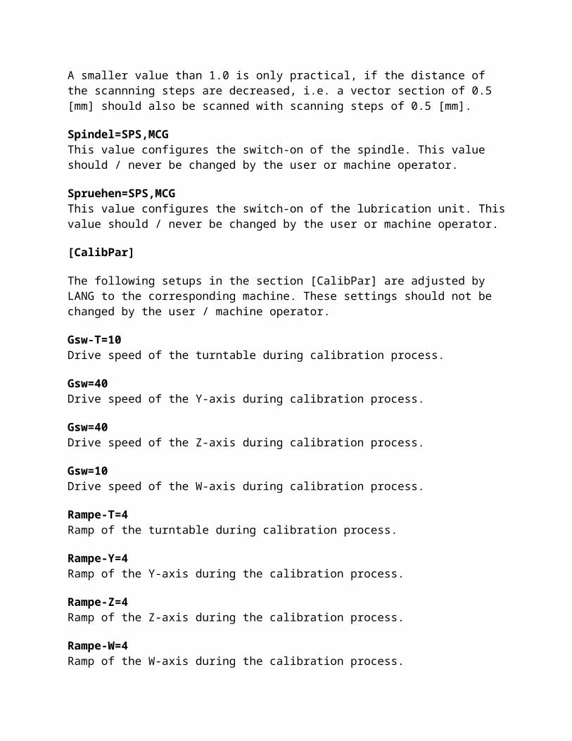
Rampe-Y=4Ramp of the Y-axis during the calibration process.
Rampe-Z=4Ramp of the Z-axis during the calibration process.
Rampe-W=4Ramp of the W-axis during the calibration process.
[SpindlePar]
Max=7000Max. achievable spindle current. Serves for display of the spindle current in the engraving-dialog.
Kritisch=5000Critical zone of spindle current (overload). Serves for display of the spindle current in the engraving-dialog.
Comparison list LCADR -> LTIREWhere to find which function ?
LCADR LTIRE
[INFO] / [LANG GMBH] [?] / [Program information]
[INFO] / [GRAPHIC FORM] Button in vertical toolbar
[INFO] / [RASTER] see: LANG-Windows-Program LCAD
[INFO] / [MOUSE] / [RESOLUTION] Windows Control Panel or a special mouse driver
[INFO] / [MOUSE] / [Circle around mouse pointer]
Button in vertical toolbar (Measuring)
[FILE] / [INIT] [File] / [New] or Button in horizontal toolbar or Strg+N
[FILE] / [DIR] Windows File Manager
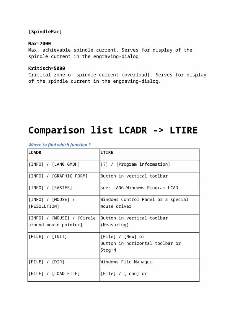
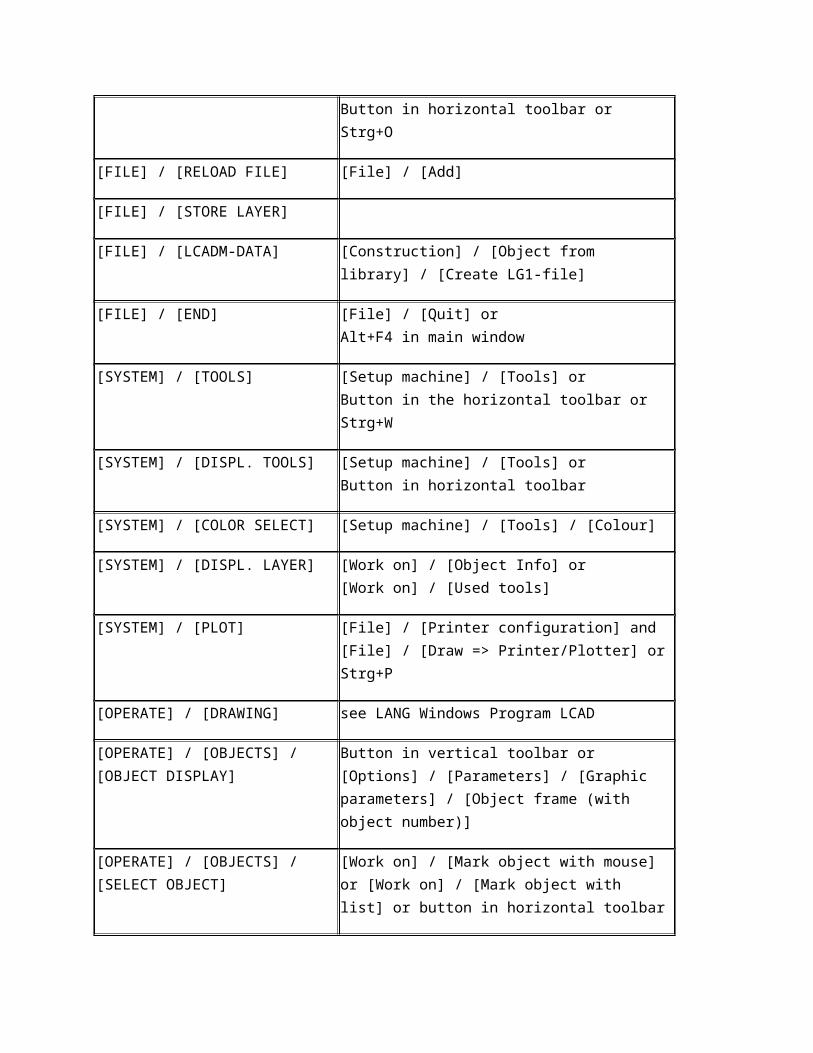
[FILE] / [LOAD FILE] [File] / [Load] orButton in horizontal toolbar or Strg+O
[FILE] / [RELOAD FILE] [File] / [Add]
[FILE] / [STORE LAYER]
[FILE] / [LCADM-DATA] [Construction] / [Object from library] / [Create LG1-file]
[FILE] / [END] [File] / [Quit] orAlt+F4 in main window
[SYSTEM] / [TOOLS] [Setup machine] / [Tools] orButton in the horizontal toolbar or Strg+W
[SYSTEM] / [DISPL. TOOLS] [Setup machine] / [Tools] orButton in horizontal toolbar
[SYSTEM] / [COLOR SELECT] [Setup machine] / [Tools] / [Colour]
[SYSTEM] / [DISPL. LAYER] [Work on] / [Object Info] or[Work on] / [Used tools]
[SYSTEM] / [PLOT] [File] / [Printer configuration] and [File] / [Draw => Printer/Plotter] or Strg+P
[OPERATE] / [DRAWING] see LANG Windows Program LCAD
[OPERATE] / [OBJECTS] / [OBJECT DISPLAY]
Button in vertical toolbar or [Options] / [Parameters] / [Graphic parameters] / [Object frame (with object number)]
[OPERATE] / [OBJECTS] / [SELECT OBJECT]
[Work on] / [Mark object with mouse] or [Work on] / [Mark object with list] or button in horizontal toolbar
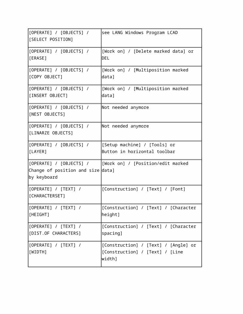
[OPERATE] / [OBJECTS] / [SELECT POSITION]
see LANG Windows Program LCAD
[OPERATE] / [OBJECTS] / [ERASE] [Work on] / [Delete marked data] orDEL
[OPERATE] / [OBJECTS] / [COPY OBJECT] [Work on] / [Multiposition marked data]
[OPERATE] / [OBJECTS] / [INSERT OBJECT]
[Work on] / [Multiposition marked data]
[OPERATE] / [OBJECTS] / [NEST OBJECTS]
Not needed anymore
[OPERATE] / [OBJECTS] / [LINARZE OBJECTS]
Not needed anymore
[OPERATE] / [OBJECTS] / [LAYER] [Setup machine] / [Tools] orButton in horizontal toolbar
[OPERATE] / [OBJECTS] / Change of position and size by keyboard
[Work on] / [Position/edit marked data]
[OPERATE] / [TEXT] / [CHARACTERSET] [Construction] / [Text] / [Font]
[OPERATE] / [TEXT] / [HEIGHT] [Construction] / [Text] / [Character height]
[OPERATE] / [TEXT] / [DIST.OF CHARACTERS]
[Construction] / [Text] / [Character spacing]
[OPERATE] / [TEXT] / [WIDTH] [Construction] / [Text] / [Angle] or[Construction] / [Text] / [Line width]
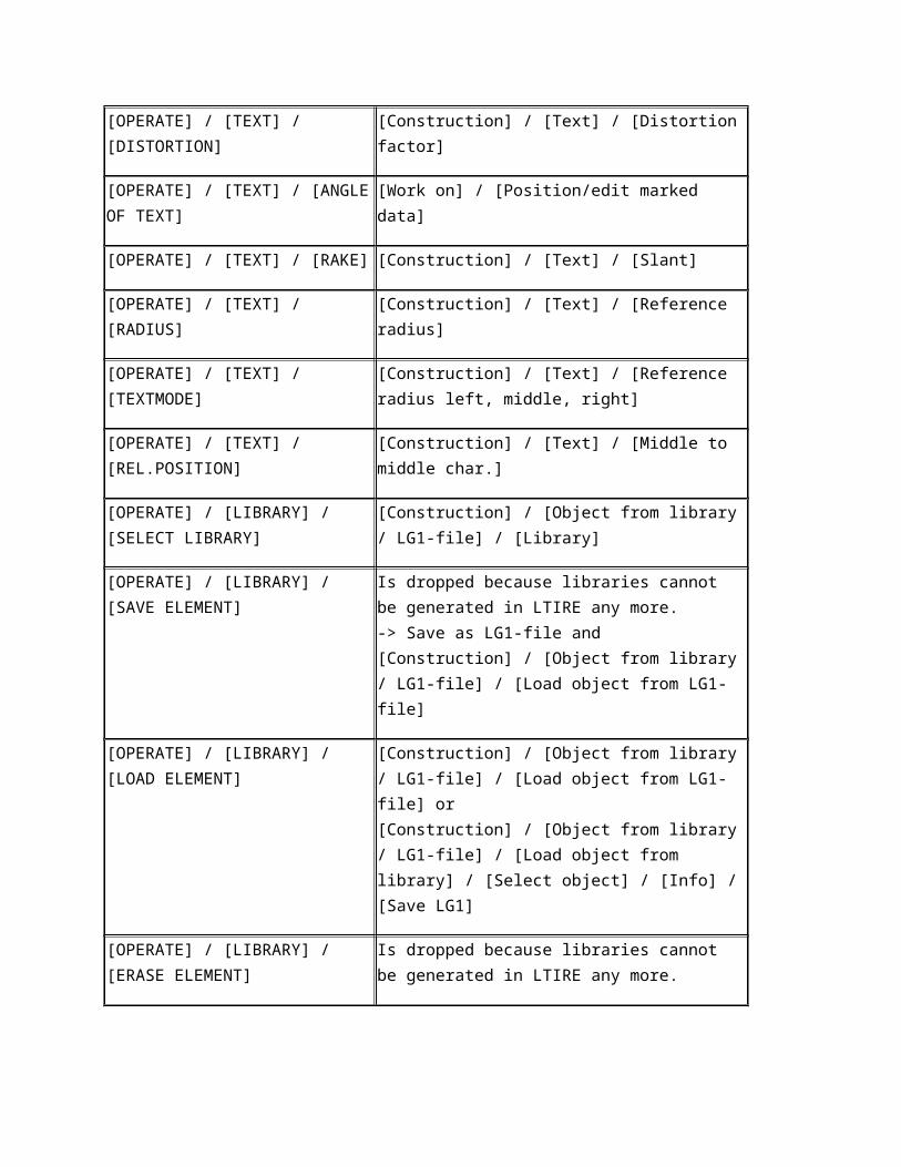
[OPERATE] / [TEXT] / [DISTORTION] [Construction] / [Text] / [Distortion factor]
[OPERATE] / [TEXT] / [ANGLE OF TEXT] [Work on] / [Position/edit marked data]
[OPERATE] / [TEXT] / [RAKE] [Construction] / [Text] / [Slant]
[OPERATE] / [TEXT] / [RADIUS] [Construction] / [Text] / [Reference radius]
[OPERATE] / [TEXT] / [TEXTMODE] [Construction] / [Text] / [Reference radius left, middle, right]
[OPERATE] / [TEXT] / [REL.POSITION] [Construction] / [Text] / [Middle to middle char.]
[OPERATE] / [LIBRARY] / [SELECT LIBRARY]
[Construction] / [Object from library / LG1-file] / [Library]
[OPERATE] / [LIBRARY] / [SAVE Is dropped because libraries cannot be generated in
ELEMENT] LTIRE any more.-> Save as LG1-file and [Construction] / [Object from library / LG1-file] / [Load object from LG1-file]
[OPERATE] / [LIBRARY] / [LOAD ELEMENT]
[Construction] / [Object from library / LG1-file] / [Load object from LG1-file] or[Construction] / [Object from library / LG1-file] / [Load object from library] / [Select object] / [Info] / [Save LG1]
[OPERATE] / [LIBRARY] / [ERASE ELEMENT]
Is dropped because libraries cannot be generated in LTIRE any more.
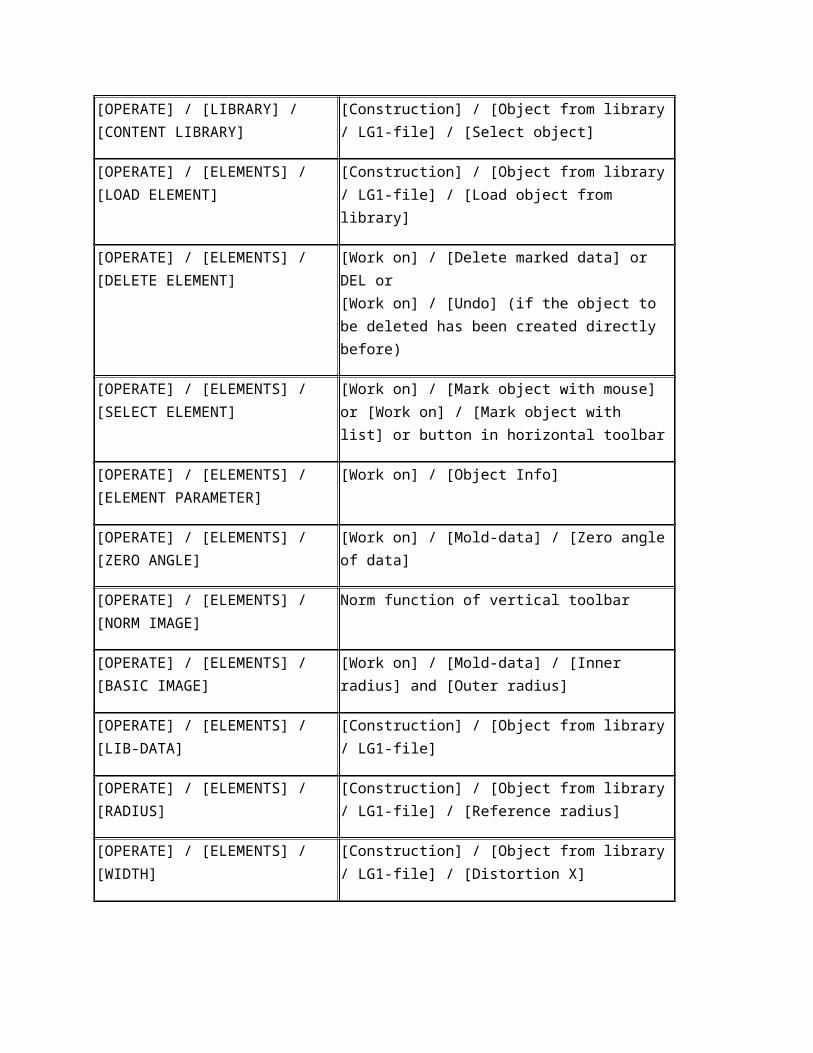
[OPERATE] / [LIBRARY] / [CONTENT LIBRARY]
[Construction] / [Object from library / LG1-file] / [Select object]
[OPERATE] / [ELEMENTS] / [LOAD ELEMENT]
[Construction] / [Object from library / LG1-file] / [Load object from library]
[OPERATE] / [ELEMENTS] / [DELETE ELEMENT]
[Work on] / [Delete marked data] orDEL or [Work on] / [Undo] (if the object to be deleted has been created directly before)
[OPERATE] / [ELEMENTS] / [SELECT ELEMENT]
[Work on] / [Mark object with mouse] or [Work on] / [Mark object with list] or button in horizontal toolbar
[OPERATE] / [ELEMENTS] / [ELEMENT PARAMETER]
[Work on] / [Object Info]
[OPERATE] / [ELEMENTS] / [ZERO ANGLE]
[Work on] / [Mold-data] / [Zero angle of data]
[OPERATE] / [ELEMENTS] / [NORM IMAGE]
Norm function of vertical toolbar
[OPERATE] / [ELEMENTS] / [BASIC IMAGE]
[Work on] / [Mold-data] / [Inner radius] and [Outer radius]
[OPERATE] / [ELEMENTS] / [LIB-DATA] [Construction] / [Object from library / LG1-file]
[OPERATE] / [ELEMENTS] / [RADIUS] [Construction] / [Object from library / LG1-file] / [Reference radius]
[OPERATE] / [ELEMENTS] / [WIDTH] [Construction] / [Object from library / LG1-file] / [Distortion X]
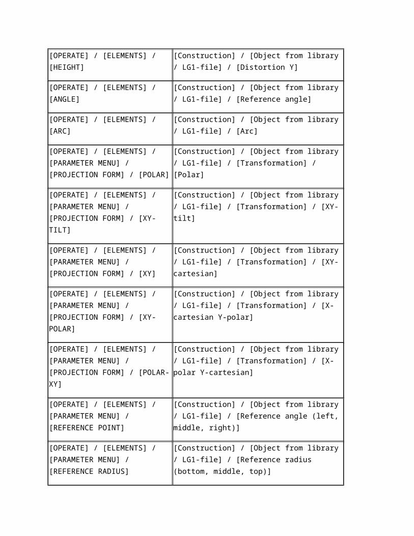
[OPERATE] / [ELEMENTS] / [HEIGHT] [Construction] / [Object from library / LG1-file] / [Distortion Y]
[OPERATE] / [ELEMENTS] / [ANGLE] [Construction] / [Object from library / LG1-file] / [Reference angle]
[OPERATE] / [ELEMENTS] / [ARC] [Construction] / [Object from library / LG1-file] / [Arc]
[OPERATE] / [ELEMENTS] / [PARAMETER MENU] / [PROJECTION FORM] / [POLAR]
[Construction] / [Object from library / LG1-file] / [Transformation] / [Polar]
[OPERATE] / [ELEMENTS] / [PARAMETER MENU] / [PROJECTION FORM] / [XY-TILT]
[Construction] / [Object from library / LG1-file] / [Transformation] / [XY-tilt]
[OPERATE] / [ELEMENTS] / [PARAMETER MENU] / [PROJECTION FORM] / [XY]
[Construction] / [Object from library / LG1-file] / [Transformation] / [XY-cartesian]
[OPERATE] / [ELEMENTS] / [PARAMETER MENU] / [PROJECTION FORM] / [XY-POLAR]
[Construction] / [Object from library / LG1-file] / [Transformation] / [X-cartesian Y-polar]
[OPERATE] / [ELEMENTS] / [PARAMETER MENU] / [PROJECTION FORM] / [POLAR-XY]
[Construction] / [Object from library / LG1-file] / [Transformation] / [X-polar Y-cartesian]
[OPERATE] / [ELEMENTS] / [PARAMETER MENU] / [REFERENCE POINT]
[Construction] / [Object from library / LG1-file] / [Reference angle (left, middle, right)]
[OPERATE] / [ELEMENTS] / [PARAMETER MENU] / [REFERENCE RADIUS]
[Construction] / [Object from library / LG1-file] / [Reference radius (bottom, middle, top)]
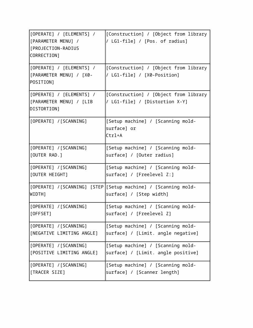
[OPERATE] / [ELEMENTS] / [PARAMETER MENU] / [PROJECTION-RADIUS CORRECTION]
[Construction] / [Object from library / LG1-file] / [Pos. of radius]
[OPERATE] / [ELEMENTS] / [PARAMETER MENU] / [X0-POSITION]
[Construction] / [Object from library / LG1-file] / [X0-Position]
[OPERATE] / [ELEMENTS] / [PARAMETER [Construction] / [Object from library / LG1-file] /
MENU] / [LIB DISTORTION] [Distortion X-Y]
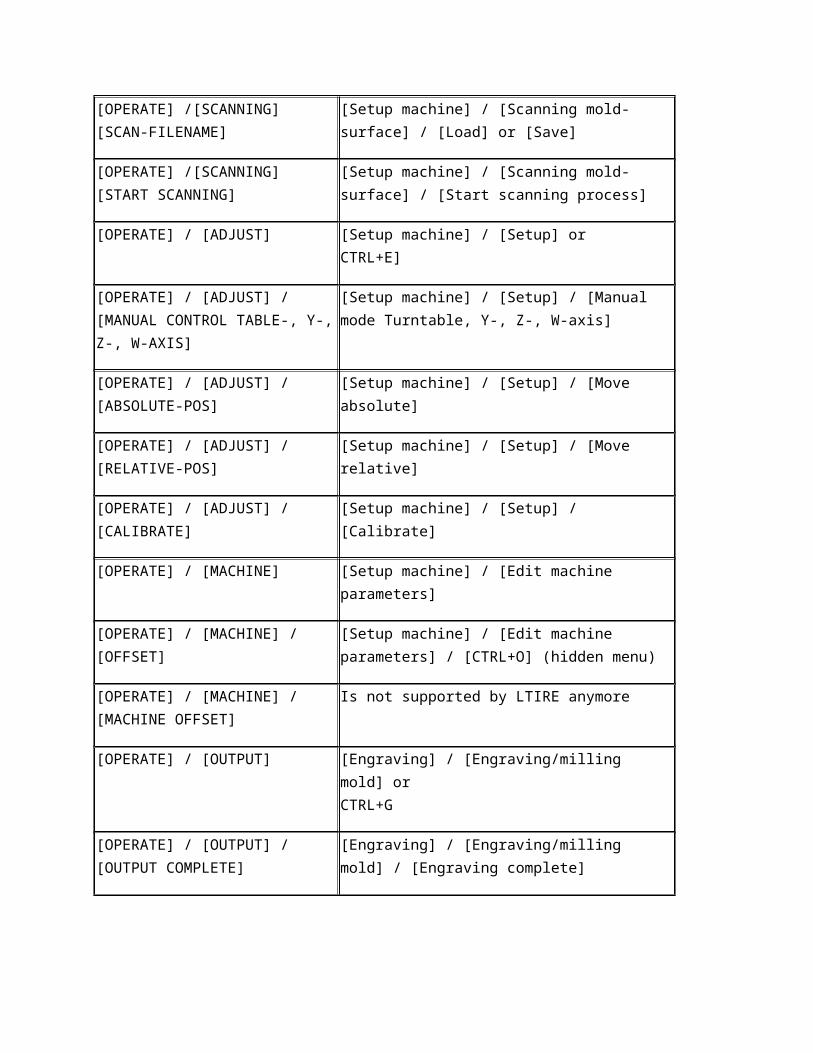
[OPERATE] /[SCANNING] [Setup machine] / [Scanning mold-surface] or Ctrl+A
[OPERATE] /[SCANNING] [OUTER RAD.] [Setup machine] / [Scanning mold-surface] / [Outer radius]
[OPERATE] /[SCANNING] [OUTER HEIGHT]
[Setup machine] / [Scanning mold-surface] / [Freelevel Z:]
[OPERATE] /[SCANNING] [STEP WIDTH] [Setup machine] / [Scanning mold-surface] / [Step width]
[OPERATE] /[SCANNING] [OFFSET] [Setup machine] / [Scanning mold-surface] / [Freelevel Z]
[OPERATE] /[SCANNING] [NEGATIVE LIMITING ANGLE]
[Setup machine] / [Scanning mold-surface] / [Limit. angle negative]
[OPERATE] /[SCANNING] [POSITIVE LIMITING ANGLE]
[Setup machine] / [Scanning mold-surface] / [Limit. angle positive]
[OPERATE] /[SCANNING] [TRACER SIZE] [Setup machine] / [Scanning mold-surface] / [Scanner length]
[OPERATE] /[SCANNING] [SCAN-FILENAME]
[Setup machine] / [Scanning mold-surface] / [Load] or [Save]
[OPERATE] /[SCANNING] [START SCANNING]
[Setup machine] / [Scanning mold-surface] / [Start scanning process]
[OPERATE] / [ADJUST] [Setup machine] / [Setup] orCTRL+E]
[OPERATE] / [ADJUST] / [MANUAL CONTROL TABLE-, Y-, Z-, W-AXIS]
[Setup machine] / [Setup] / [Manual mode Turntable, Y-, Z-, W-axis]
[OPERATE] / [ADJUST] / [ABSOLUTE-POS]
[Setup machine] / [Setup] / [Move absolute]
[OPERATE] / [ADJUST] / [RELATIVE-POS] [Setup machine] / [Setup] / [Move relative]
[OPERATE] / [ADJUST] / [CALIBRATE] [Setup machine] / [Setup] / [Calibrate]
[OPERATE] / [MACHINE] [Setup machine] / [Edit machine parameters]
[OPERATE] / [MACHINE] / [OFFSET] [Setup machine] / [Edit machine parameters] / [CTRL+O] (hidden menu)
[OPERATE] / [MACHINE] / [MACHINE OFFSET]
Is not supported by LTIRE anymore
[OPERATE] / [OUTPUT] [Engraving] / [Engraving/milling mold] orCTRL+G
[OPERATE] / [OUTPUT] / [OUTPUT COMPLETE]
[Engraving] / [Engraving/milling mold] / [Engraving complete]
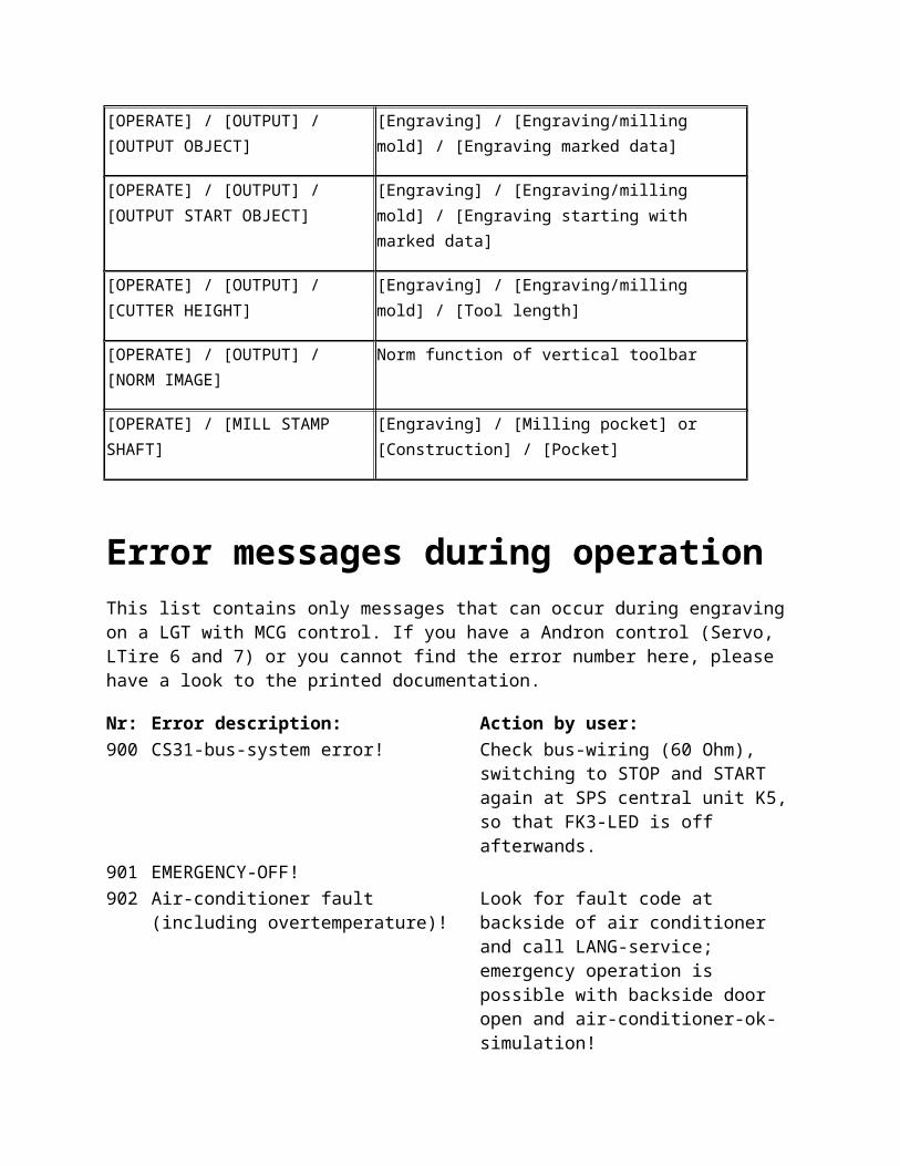
[OPERATE] / [OUTPUT] / [OUTPUT OBJECT]
[Engraving] / [Engraving/milling mold] / [Engraving marked data]
[OPERATE] / [OUTPUT] / [OUTPUT START OBJECT]
[Engraving] / [Engraving/milling mold] / [Engraving starting with marked data]
[OPERATE] / [OUTPUT] / [CUTTER HEIGHT]
[Engraving] / [Engraving/milling mold] / [Tool length]
[OPERATE] / [OUTPUT] / [NORM IMAGE] Norm function of vertical toolbar
[OPERATE] / [MILL STAMP SHAFT] [Engraving] / [Milling pocket] or[Construction] / [Pocket]
Error messages during operationThis list contains only messages that can occur during engraving on a LGT with MCG control. If you have a Andron control (Servo, LTire 6 and 7) or you cannot find the error number here, please have a look to the printed documentation.
Nr: Error description: Action by user:900 CS31-bus-system error! Check bus-wiring (60 Ohm), switching to
STOP and START again at SPS central unit K5, so that FK3-LED is off afterwands.
901 EMERGENCY-OFF!
902 Air-conditioner fault (including overtemperature)!
Look for fault code at backside of air conditioner and call LANG-service; emergency operation is possible with backside door open and air-conditioner-ok-simulation!
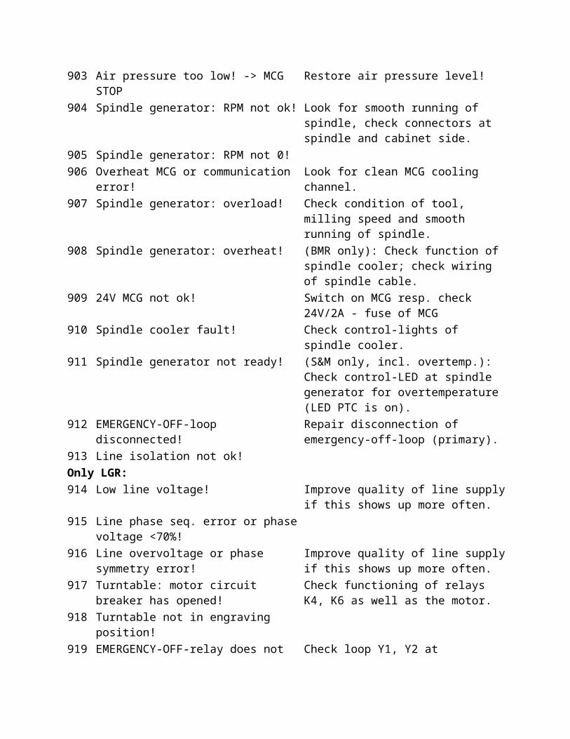
903 Air pressure too low! -> MCG STOP Restore air pressure level!904 Spindle generator: RPM not ok! Look for smooth running of spindle, check
connectors at spindle and cabinet side.905 Spindle generator: RPM not 0! 906 Overheat MCG or communication error! Look for clean MCG cooling channel.907 Spindle generator: overload! Check condition of tool, milling speed and
smooth running of spindle.908 Spindle generator: overheat! (BMR only): Check function of spindle
cooler; check wiring of spindle cable.909 24V MCG not ok! Switch on MCG resp. check 24V/2A - fuse of
MCG910 Spindle cooler fault! Check control-lights of spindle cooler.911 Spindle generator not ready! (S&M only, incl. overtemp.): Check control-
LED at spindle generator for overtemperature (LED PTC is on).
912 EMERGENCY-OFF-loop disconnected! Repair disconnection of emergency-off-loop (primary).
913 Line isolation not ok! Only LGR:914 Low line voltage! Improve quality of line supply if this shows
up more often.915 Line phase seq. error or phase voltage <70%! 916 Line overvoltage or phase symmetry error! Improve quality of line supply if this shows
up more often.917 Turntable: motor circuit breaker has opened! Check functioning of relays K4, K6 as well as
the motor.918 Turntable not in engraving position! 919 EMERGENCY-OFF-relay does not release! Check loop Y1, Y2 at emergency-off-relay
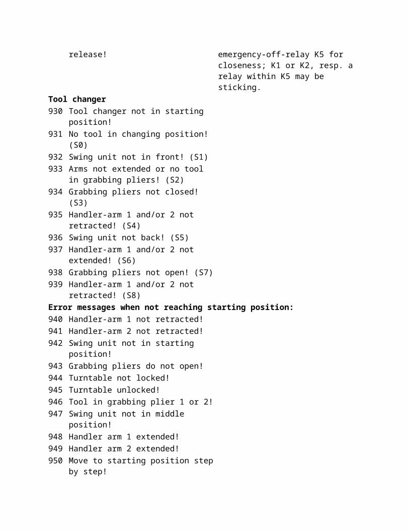
K5 for closeness; K1 or K2, resp. a relay within K5 may be sticking.
Tool changer930 Tool changer not in starting position! 931 No tool in changing position! (S0) 932 Swing unit not in front! (S1) 933 Arms not extended or no tool in grabbing
pliers! (S2)
934 Grabbing pliers not closed! (S3) 935 Handler-arm 1 and/or 2 not retracted! (S4) 936 Swing unit not back! (S5)
937 Handler-arm 1 and/or 2 not extended! (S6) 938 Grabbing pliers not open! (S7) 939 Handler-arm 1 and/or 2 not retracted! (S8) Error messages when not reaching starting position:940 Handler-arm 1 not retracted! 941 Handler-arm 2 not retracted! 942 Swing unit not in starting position! 943 Grabbing pliers do not open! 944 Turntable not locked! 945 Turntable unlocked! 946 Tool in grabbing plier 1 or 2! 947 Swing unit not in middle position! 948 Handler arm 1 extended! 949 Handler arm 2 extended! 950 Move to starting position step by step!
Tasks: How to scan a tire sidewall?This page describes roughly how to scan a side wall. A more precise description of the dialog 'scanning mold surface' can be found here.
Put tire sidewall on turntable and position centrally.
Central positioning is very important, because otherwise big differences in the immerging depth could occur during engraving.
Fix scanner in the spindle holder.
Standard scanner
The function of the scanner can be checked, by pressing a finger lightly on the tip of the scanner. In this case a small red lamp must light up on the upper side of the scanner. If it does not either the scanner is defective, or the cable connection between scanner and MCG control is interrupted.The LGT-S has an additional safety feature. If the tip is pressed to deep, an emergency stop is caused. If the scanner crashed somewhere, it will not be destroyed. To release the emergency stop, remove the scanner from the spindle or push a special key inside of the control cabinet.
Infrared scanner (LGT-S only)If an infrared scanner is installed and resides in the tool changer, it can be changed automatically. See 'scanning mold surface' for furhter info.
Move machine to position in front of first scan point.
For doing this use the dialog 'scanning mold surface'. The LGT-S can be moved with the hand control unit, for the LGT with MCG use the menu 'Move axis manual'. The scan start position is reached the easiest by the function 'Manual axes drive'. The scanning process moves always from the inside to the outside, i.e. the scan start position is the position on the sidewall lying furthest to the inside. Pay attention to positioning the tool axes as vertical as possible to the sidewall surface. The scanning start position should be c. 2-5-[mm] apart from the sidewall surface.
Note: Scanning is difficult if ridges and grooves are turned in the tire sidewall, because the tool axis must compensate big angle changes at these points. In this case it is advisable to bridge ridges and grooves or to scan the tire sidewall partially, i.e. the sidewall is divided into sections.
Start scanning
Procedure for scanning:
First the sidewall of the tire is "pre-scanned" with double step width up to the fixed outer radius. Then it is moved back to the scan start position and the sidewall of the tire is scanned with single (normal) step width.
Poti 1 controls the positioning speed and Poti 3 the scanning speed. The scan procedure runs automatically until the end. During the scanning procedure, the swivel axis always positions itself vertically to the surface of the tire sidewall.
The scan process can be aborted at any time with the <ESC> key.
Correct tool axis angle if necessary
The swivel angle of the scan data can be adjusted by the function 'Tool axis angle'.
Save scanning data
It is advisable to store the scan data. Otherwise, if the program is interrupted or finished, the scan process has to be repeated
Machine: Scanning mold surface The scan menu serves for scanning the form cross-section of a tire side-wall which is centrally clamped on the turntable, and for making the data available for later procedures. See also: How to scan a tire
side-wall?
Note
Depending on the machine type some dialog elements are not available. For further information see the descriptions beneath.
This dialog can be reached with the symbol from the horizontal toolbar.
Position of the probe tip
This part of the dialog shows the current probe tip position. Depending on the machine type the axes can be moved through the button [Axes] (only LTire 5 for MCG), or with the hand control unit (only LTire 6 for Andron control). A new dialog opens for moving the axes.
Measuring probe / Probe length
The box [Probe length] displays the probe length, which is measured from the middle of the rotation axe to the probe tip. This value is measured once during setup of the machine and must only be changed, when the probe is modified or exchanged. Usually the probe length is between 100 and 120 mm.
Note
A wrong probe length result in a faulty engraving! On machines without a reference area (only MCG) the probe tip length must be measured and
entered manually. On all other machines the length cannot be modified.
Outer radius
Defines the position on the Y-axis at which the scanning is to be ended. The scan procedure happens always from inside to outside. I.e. if the Outer radius is reached, the scan procedure is stopped.
Z offset
States the distance of the scanner tip to the side-wall surface when positioning on next scanning position. This value should be within the range 1 - 5 [mm].
Step width
Gives the distance between the scanner positions. The Step width should be reduced for strongly bent curves, while a larger step width can be selected for very flat tire side-walls. The Step width should be within the range 1 - 5 [mm]. A Step width of 2 [mm] has proven useful in many cases.
Limit. angle positive / negative
The swivel area of the tool axis (W-axis) can be limited by this function. This function can be used especially for tire side-walls with already installed profile segments. So the scanner could not swivel without colliding with these segments.
Note
Before starting the scan procedure the tool axis has to be within the intervall of the limit. angle.
Start scanning process
The scanning process starts at the machine current position.
Load
An already existing scan file (*.ABT) can be loaded.
Save
The data determined during the process can be saved in a *.ABT-file.
Edit
The scan data of all 4 axes are displayed here and can be changed. The import of scanning curves in LG1- or HPGL-format can be done here as well. See: Edit scan data
Display
The current scanning data can be displayed graphicaly.
Manual movingWith this dialog the axis of the machine can be moved with the keyboard:
Hints:
This dialog is only available within LTire 5 with the MCG. The LGT-S can be moved with the hand held control-unit only.
The axis moves as long the appropriate key is pushed. For testing and setup purpose the turntable can turned on permanently with the buttons
"Negative" and "Positive". The permanent mode can be stopped by klicking the same button again or by closing the dialog.
See also:
Setup machine Scan surface
Setup machine: Adjust the angle of tool axis of scanning dataThe swivel angle of the scanning data (tool axis) can be adjusted by this function. Generally this dialog is for special purposes only. In earlier versions of LTire this function was used to achieve speed improvements during engraving. This is not necessary any more due to better internal smothing functions.
There are 3 functions available:
Set angle to a fix value , Smooth angle (old version, for compatibility reasons), and Recalculate angle from x- and y-positions .
Note:
The result of these operations can and shlould be reviewed with the dialog Display scanning data.
Set angle to a fix valueWith this function the angle will be set to a fix value between two positions. E. g. the angle can be set to 0 for the whole sidewall data.
Steps:
Check the control box [Set fixed angle between 2 scanning positions]. When only a part of the data should be changed, select the first position in [First position (no.)]
and the last position in [Last position (no.)] Set the value for the angle in [Angle:]. Close the dialog with the button OK. The result can be rewieved with Display scanning data.
Smoth angle
The angle of the scanning data are modified, so that a constant motion of the swivel axis happens within the selected area. The inevitable succession is, that all axes run more evenly. Time-consuming brake and start ramps are partially dropped completely. The smoothing msut only be used for scanning data with constant curvature.
The angles of the scanning data (tool axis) are smoothed between two positions, that have to be defined
Attention: After smoothing the swivel axis position is not exactly vertical on the material surface, but this mistake might be neglected in almost all cases!
Example:
Example:
Example:
Recalculate angle from x- and y-positionsThe angles of the scanning data (tool axis) are calculated by the scanned values of Y- and Z-axis. Hereby it is assured, that the swivel axis is always standing exactly vertically on the material surface. Since the angles describe no even contour the necessity for driving time-consuming brake and start ramps frequently might arise.
Display scanning data
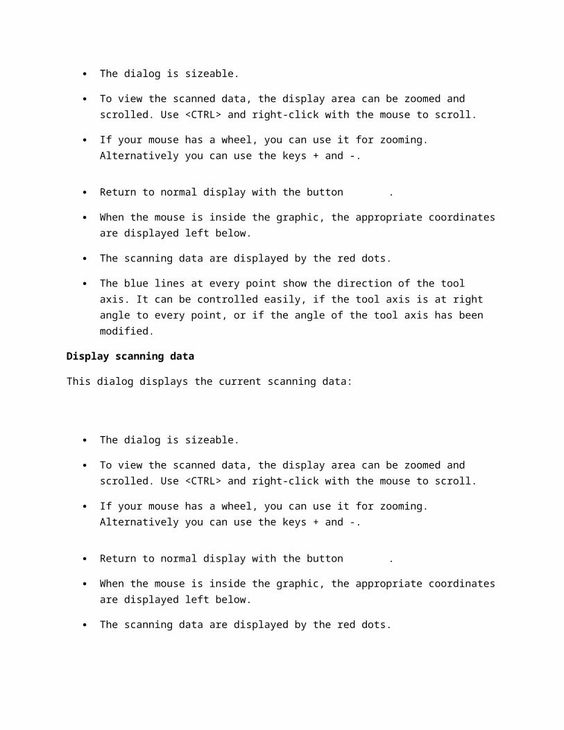
This dialog displays the current scanning data:
The dialog is sizeable.
To view the scanned data, the display area can be zoomed and scrolled. Use <CTRL> and right-click with the mouse to scroll.
If your mouse has a wheel, you can use it for zooming. Alternatively you can use the keys + and -.
Return to normal display with the button .
When the mouse is inside the graphic, the appropriate coordinates are displayed left below.
The scanning data are displayed by the red dots.
The blue lines at every point show the direction of the tool axis. It can be controlled easily, if the tool axis is at right angle to every point, or if the angle of the tool axis has been modified.
Display scanning data
This dialog displays the current scanning data:
The dialog is sizeable.
To view the scanned data, the display area can be zoomed and scrolled. Use <CTRL> and right-click with the mouse to scroll.
If your mouse has a wheel, you can use it for zooming. Alternatively you can use the keys + and -.
Return to normal display with the button .
When the mouse is inside the graphic, the appropriate coordinates are displayed left below.
The scanning data are displayed by the red dots.
The blue lines at every point show the direction of the tool axis. It can be controlled easily, if the tool axis is at right angle to every point, or if the angle of the tool axis has been modified.
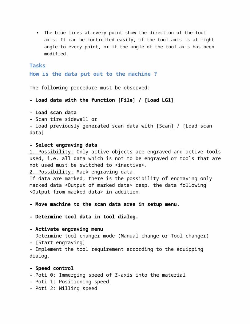
Tasks How is the data put out to the machine ?
The following procedure must be observed:
- Load data with the function [File] / [Load LG1]
- Load scan data- Scan tire sidewall or - load previously generated scan data with [Scan] / [Load scan data]
- Select engraving data1. Possibility: Only active objects are engraved and active tools used, i.e. all data which is not to
be engraved or tools that are not used must be switched to <inactive>.2. Possibility: Mark engraving data. If data are marked, there is the possibility of engraving only marked data <Output of marked data> resp. the data following <Output from marked data> in addition.
- Move machine to the scan data area in setup menu.
- Determine tool data in tool dialog.
- Activate engraving menu- Determine tool changer mode (Manual change or Tool changer)- [Start engraving]- Implement the tool requirement according to the equipping dialog.
- Speed control - Poti 0: Immerging speed of Z-axis into the material- Poti 1: Positioning speed - Poti 2: Milling speed- Poti 3: Is not active during engraving/milling. It is used for special functions, such as calibrating for example.
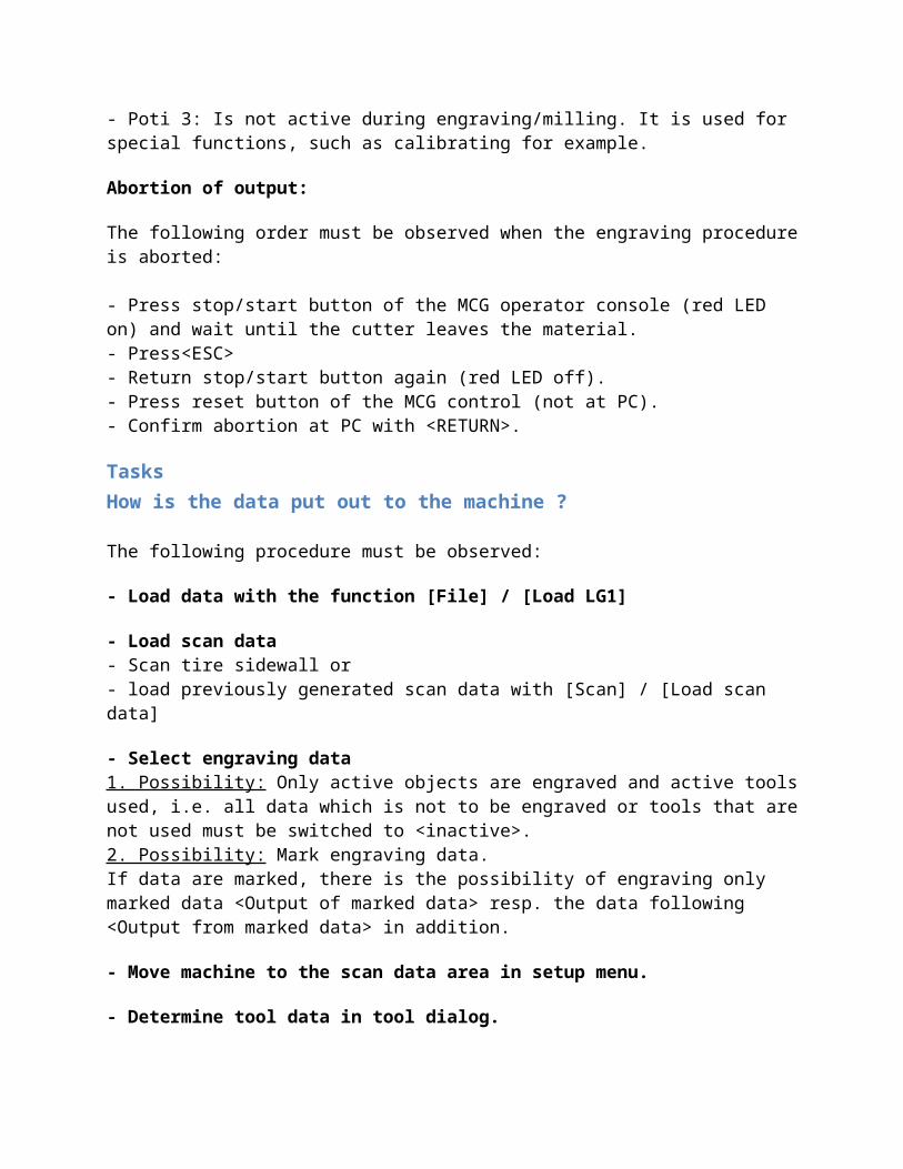
Abortion of output:
The following order must be observed when the engraving procedure is aborted:
- Press stop/start button of the MCG operator console (red LED on) and wait until the cutter leaves the material.- Press<ESC>- Return stop/start button again (red LED off).- Press reset button of the MCG control (not at PC).- Confirm abortion at PC with <RETURN>.
Tasks How is the data put out to the machine ?
The following procedure must be observed:
- Load data with the function [File] / [Load LG1]
- Load scan data- Scan tire sidewall or - load previously generated scan data with [Scan] / [Load scan data]
- Select engraving data1. Possibility: Only active objects are engraved and active tools used, i.e. all data which is not to be engraved or tools that are not used must be switched to <inactive>.
2. Possibility: Mark engraving data. If data are marked, there is the possibility of engraving only marked data <Output of marked data> resp. the data following <Output from marked data> in addition.
- Move machine to the scan data area in setup menu.
- Determine tool data in tool dialog.
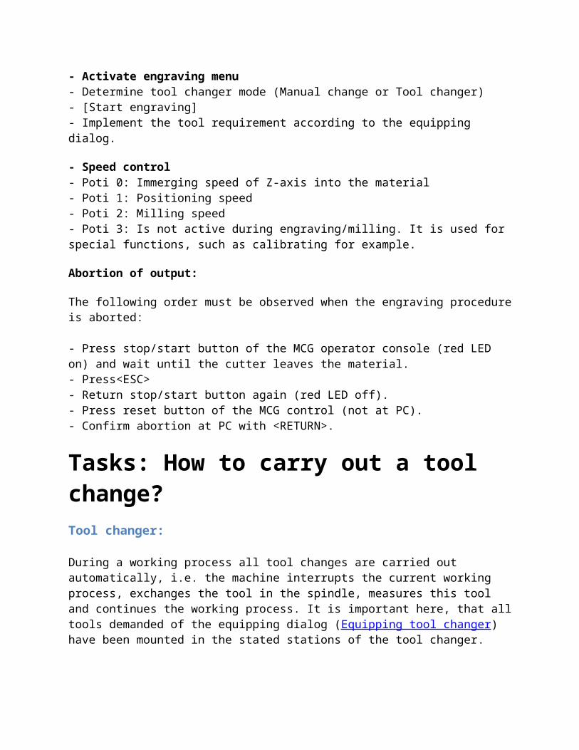
- Activate engraving menu- Determine tool changer mode (Manual change or Tool changer)- [Start engraving]- Implement the tool requirement according to the equipping dialog.
- Speed control - Poti 0: Immerging speed of Z-axis into the material- Poti 1: Positioning speed - Poti 2: Milling speed- Poti 3: Is not active during engraving/milling. It is used for special functions, such as calibrating for example.
Abortion of output:
The following order must be observed when the engraving procedure is aborted:
- Press stop/start button of the MCG operator console (red LED on) and wait until the cutter leaves the material.- Press<ESC>- Return stop/start button again (red LED off).- Press reset button of the MCG control (not at PC).- Confirm abortion at PC with <RETURN>.
Tasks: How to carry out a tool change?Tool changer:
During a working process all tool changes are carried out automatically, i.e. the machine interrupts the current working process, exchanges the tool in the spindle, measures this tool and continues the working process. It is important here, that all tools demanded of the equipping dialog (Equipping tool changer) have been mounted in the stated stations of the tool changer.
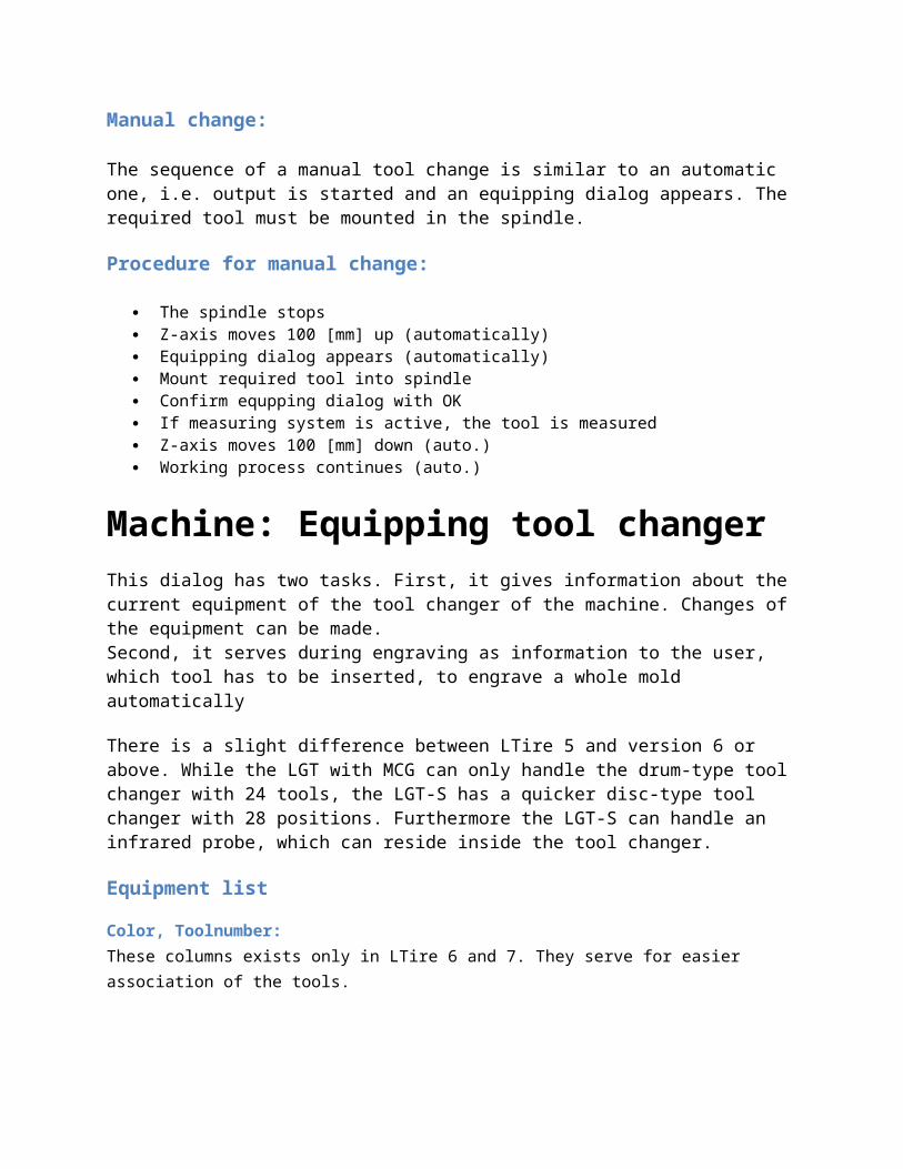
Manual change:
The sequence of a manual tool change is similar to an automatic one, i.e. output is started and an equipping dialog appears. The required tool must be mounted in the spindle.
Procedure for manual change:
The spindle stops Z-axis moves 100 [mm] up (automatically) Equipping dialog appears (automatically) Mount required tool into spindle Confirm equpping dialog with OK If measuring system is active, the tool is measured Z-axis moves 100 [mm] down (auto.) Working process continues (auto.)
Machine: Equipping tool changerThis dialog has two tasks. First, it gives information about the current equipment of the tool changer of the machine. Changes of the equipment can be made.Second, it serves during engraving as information to the user, which tool has to be inserted, to engrave a whole mold automatically
There is a slight difference between LTire 5 and version 6 or above. While the LGT with MCG can only handle the drum-type tool changer with 24 tools, the LGT-S has a quicker disc-type tool changer with 28 positions. Furthermore the LGT-S can handle an infrared probe, which can reside inside the tool changer.
Equipment list
Color, Toolnumber:These columns exists only in LTire 6 and 7. They serve for easier association of the tools.
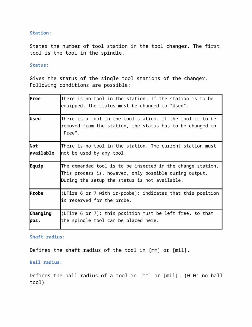
Station:
States the number of tool station in the tool changer. The first tool is the tool in the spindle.
Status:
Gives the status of the single tool stations of the changer. Following conditions are possible:
Free There is no tool in the station. If the station is to be equipped, the status must be changed to "Used".
Used There is a tool in the tool station. If the tool is to be removed from the station, the status has to be changed to "Free".
Not available There is no tool in the station. The current station must not be used by any tool.

Equip The demanded tool is to be inserted in the change station. This process is, however, only possible during output. During the setup the status is not available.
Probe (LTire 6 or 7 with ir-probe): indicates that this position is reserved for the probe.
Changing pos. (LTire 6 or 7): this position must be left free, so that the spindle tool can be placed here.
Shaft radius:
Defines the shaft radius of the tool in [mm] or [mil].
Ball radius:
Defines the ball radius of a tool in [mm] or [mil]. (0.0: no ball tool)
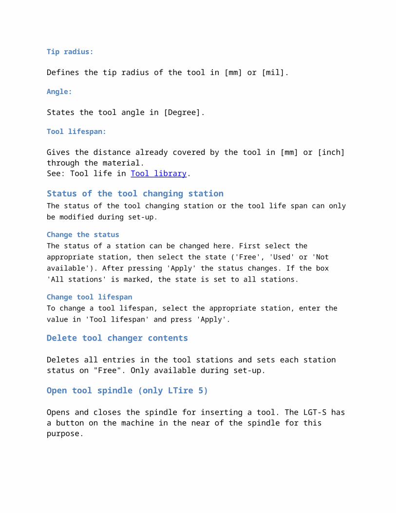
Tip radius:
Defines the tip radius of the tool in [mm] or [mil].
Angle:
States the tool angle in [Degree].
Tool lifespan:
Gives the distance already covered by the tool in [mm] or [inch] through the material.See: Tool life in Tool library.
Status of the tool changing stationThe status of the tool changing station or the tool life span can only be modified during set-up.
Change the statusThe status of a station can be changed here. First select the appropriate station, then select the state ('Free', 'Used' or 'Not available'). After pressing 'Apply' the status changes. If the box 'All stations' is marked, the state is set to all stations.
Change tool lifespanTo change a tool lifespan, select the appropriate station, enter the value in 'Tool lifespan' and press 'Apply'.
Delete tool changer contents
Deletes all entries in the tool stations and sets each station status on "Free". Only available during set-up.
Open tool spindle (only LTire 5)
Opens and closes the spindle for inserting a tool. The LGT-S has a button on the machine in the near of the spindle for this purpose.
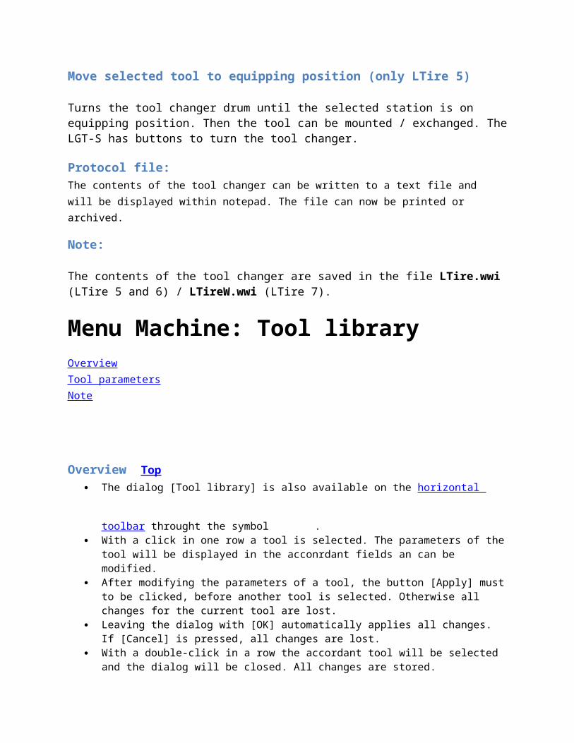
Move selected tool to equipping position (only LTire 5)
Turns the tool changer drum until the selected station is on equipping position. Then the tool can be mounted / exchanged. The LGT-S has buttons to turn the tool changer.
Protocol file:The contents of the tool changer can be written to a text file and will be displayed within notepad. The file can now be printed or archived.
Note:
The contents of the tool changer are saved in the file LTire.wwi (LTire 5 and 6) / LTireW.wwi (LTire 7).
Menu Machine: Tool library OverviewTool parametersNote
Overview Top
The dialog [Tool library] is also available on the horizontal toolbar throught the symbol .
With a click in one row a tool is selected. The parameters of the tool will be displayed in the acconrdant fields an can be modified.
After modifying the parameters of a tool, the button [Apply] must to be clicked, before another tool is selected. Otherwise all changes for the current tool are lost.
Leaving the dialog with [OK] automatically applies all changes. If [Cancel] is pressed, all changes are lost.
With a double-click in a row the accordant tool will be selected and the dialog will be closed. All changes are stored.
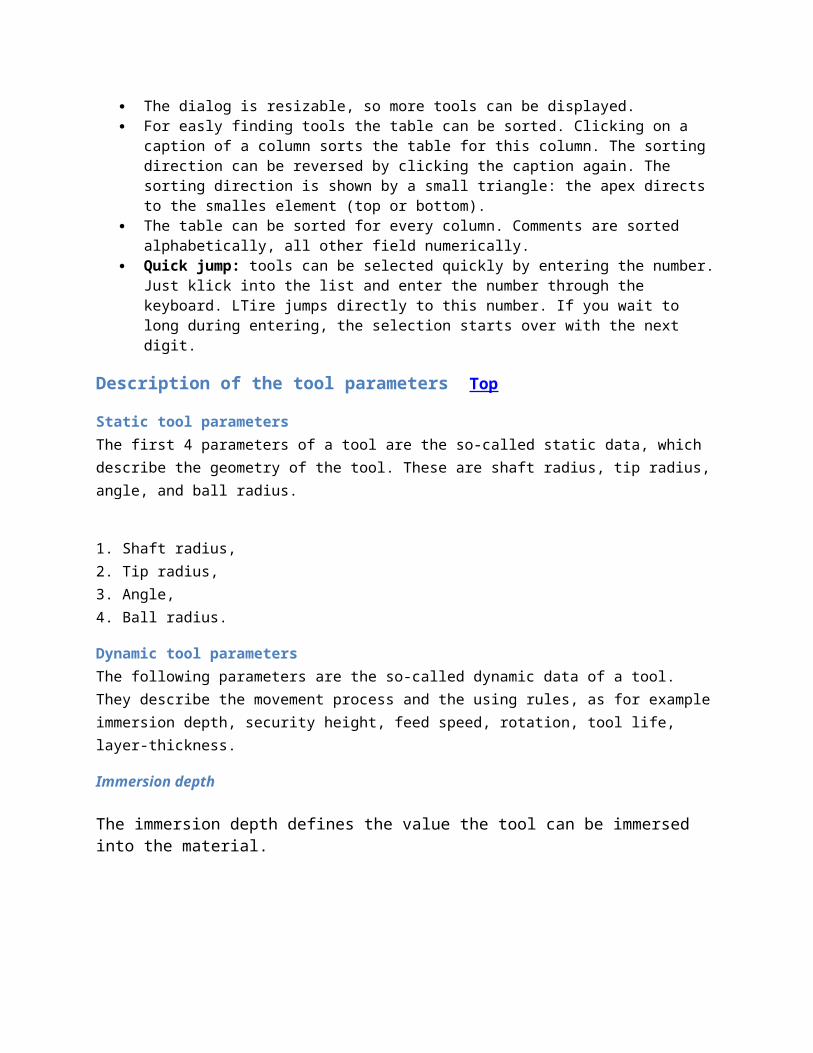
The dialog is resizable, so more tools can be displayed. For easly finding tools the table can be sorted. Clicking on a caption of a column sorts the table
for this column. The sorting direction can be reversed by clicking the caption again. The sorting direction is shown by a small triangle: the apex directs to the smalles element (top or bottom).
The table can be sorted for every column. Comments are sorted alphabetically, all other field numerically.
Quick jump: tools can be selected quickly by entering the number. Just klick into the list and enter the number through the keyboard. LTire jumps directly to this number. If you wait to long during entering, the selection starts over with the next digit.
Description of the tool parameters Top
Static tool parametersThe first 4 parameters of a tool are the so-called static data, which describe the geometry of the tool. These are shaft radius, tip radius, angle, and ball radius.
1. Shaft radius,2. Tip radius,3. Angle,4. Ball radius.
Dynamic tool parametersThe following parameters are the so-called dynamic data of a tool. They describe the movement process and the using rules, as for example immersion depth, security height, feed speed, rotation, tool life, layer-thickness.
Immersion depth
The immersion depth defines the value the tool can be immersed into the material.
Security height
The security height defines the distance of the tooltip to the material surface during an emmersed movement.
Feed speed
Defines the feed speed of the tool within the material. According to LTire version this value has different meanings:
LTire 5:The value of the speed will be defined in percent of the maximum feed speed. The field is limited to values between 0 and 100. A value of 0 has the same effect as 100.
LTire 6 and 7:The value of the feed speed will be defined in [mm per min] or [IPM] (Inch per minute) and corresponds to the speed of the tooltip. A value of 0 leads to an error. When one of the axes of the machines reaches its limit, the resulting speed may be slower than the entered feed speed value.
Rotation
The rotational speed of the milling spindle can be set here. With the respective poti on the hand-held control unit the rotation speed can be adjusted manually in the range of ±50%. The defined speed will be maintained throughout the milling process.
Tool life
This is the length of a path a cutter can cover, until it shows signs of wear, causing the tool to be re-ground or replaced. The defined tool life finally decides when a tool is to be re-ground or replaced, respectively.
Layer thickness
The layer-thickness defines the maximum immersion depth of a tool in the material in one operation, i.e. the required immersion depth can be processed in a number of operations. A defined layer-thickness of 0.0 de-activates layer-thickness milling, i.e. the milling process occurs in one operation.
Comment
A note or comment can be entered here. It only serves the personal information, and has no effect on the milling process. A comment can consist of up to 18 (LTire 5 and 6) / 75 (LTire 7) characters.
Colour
The Windows color dialog can be called by clicking to the button [Color], with which a color can be assigned to a tool. This facilitates the visual distinction of tools, and tool paths. A detailed help-description for the Windows color catalogue is provided in the Windows system control (Setup / Colors...).
Copy
The selected tool data of the tool library will be saved in the temporary tool memory with the function [Copy].
The data in the temporary tool memory can be assigned to another tool number via the function [Transfer]. The memory contents will be erased as soon as the dialog is left.
=> LTool.txt / LToolW.txt:
The content of the tool library is used to create a text file named LTool.txt (ANSI, LTire 5 and 6) / LToolW.txt (Unicode, LTire 7) and is saved in the directory of the application. This textfile can be loaded and printed with any text program (for example Notepad). This printout serves as information for already entered tools.
Tool Preview
Meaningful static parameters of a selected tool will be displayed as a drawing on the lower left of the display screen. A double click to the drawing or the tool list will enlarge (zoom) the display.
Note: Top
The displayed order is not the sequence of the tools during engraving. Engraving always starts with the lowest tool number.
The dialog does not remember the sorting order. When opening the dialog, the table is sorted by the tool number.
LTire 6 and 7: When taking over tool library’s that were created with LTire 5 or lower, this value must be adapted because the value was given in percentage of the maximum speed.
The feedrate can additionally be controlled with the poti „federate“ and „Master/Rapid“ of the hand held control unit ( for operating the hand held control unit see machine documentation). The feedrate value entered in the tool library will be moved exactly, if in the dialog “Output” in the group “poti-settings” the value for the movement- poti “Feedrate” is 100% ( see also chapter 8.2 “Engraving /milling mold).
A ball tool can not be used during cutter radius compensation for corner clearing, otherwise the of workpiece becomes defective in the corner areas. In that case the message ‘Invalid tool’ will occur.
A cutter is a ball cutter if its ball radius is unequal 0.0.
Tasks What is to be noted when milling 3D ?
The LTIRE program is capable of reading 3D-LG1-files and transferring them to the machine. These LG1-files may contain any contours, such as stamps, reliefs or data projected on any surfaces for example.
Procedure:
- Load LG1-file
- State parameters for LG1-files
-Setup tool
- Start engraving
The management of the passes is also active for 3D-data, i.e. during the 3D-output it is also milled in layers, if a tool with pass has been stated in the tool library.
The max. depth of the 3D-engraving can either be determined by the perspective depiction or in the Object-Info-Dialog
File: Open The file, selected in the file menu, is loaded into the working memory of the current LTire-application. Files in the format *.LG1 and *.LG2 can be loaded directly. Depending on add-ons several other file formats can be imported, e. g. HPGL, DXF and some more.
If an LG1-file is chosen, which is not a tire file from LCADR, a dialog for entering the Parameters for LG1-files appears. This dialog appears when importing other formats, too.
Note:
The file is completely loaded into the main memory. I.e. there has to be enough memory available.
The command Load can be activated by the button in the horizontal toolbar.
The command Load is undone by the Undo -Function . When importing files, the foreign format is converted to LG1 first. The progress of the
conversion is shown in the status bar. When importin files, it may be usefull to sort and close contours.
See also:
Add a file Sort and close selected contours
Parameters for LG1-filesThis dialog appears allways when importing data from foreign file formats. It appears also when loading LG1-files, that are not from LCADR.
Tool numberA fix layer number can be assigned to the loaded contours.
Radius for engraving
This radius value in millimetres [mm] or [inch] will be taken in account during the output, if the engraving mode is defined as roll on surface. Up to the value of the radius the radius is measured on the chord, afterwards the character will be rolled on the surface. If the engraving mode is defined as project on surface, the value of the radius is irrelevant.
Engraving mode
Roll on the surface
Up to the reference radius it is measured on the chord, afterwards the object is rolled on the surface.
Projected (on surface)
Vertical parallel projection: Every radius is measured on the chord.
Edit: Sort and close selected contoursWith this menu item selected contours can be closed. The tolerance for closing can be selected with the dialog 'Options' on the tab 'Close'. This function can be very usefull when importing data from other file formats like DXF.
Options: ParametersThis dialog allows to modify several parameters. It consists of the following tabs:
Working frameGraphicCloseResolutionClipboardVectorfilter
Working frame
A working area can be defined here.This working area is defined by a rectangle and is supposed to display the working area of the application. If frequently only a certain part of the side-wall is processed, the working area can be defined for this section of the side-wall. With the function
Standardization to working frame only this section of the side wall drawing is displayed. The working area frame does not effect the engraving.
Display working frame
The working frame can be activated / inactivated here.
Graphic
Tool path simulationAll immerged motions of the cutter are drawn with the equivalent cutter diameter. So it is easier to recognize, whether the selected contour distance is correct or not. This display mode can be enabled
with from the vertical toolbar. BaseThe drawing line width responds to the tip diameter (2 * tip radius) of the tool on the bottom of engraving.
Surface of materialThe drawing line width results from the tool radius (depending on tool geometry and immerging depth) on the material surface.
Draw drilling symbol
When the checkmark is set, for each drilling hole a small symbol will be displayed. When many drilling holes are used the display can be very complex, so sometimes it is easier to switch them off.
Show positions automaticallyWith this option, positions of selected contours will be shown automatically without activating
the function Display position marks from the vertical toolbar.
Close
The tolerance for closing contours with the function Sort and close selected contours can be entered here.
See also: Sort and close selected contours.
Resolution
Scroller resolution
States the value by which the screen display is shifted, in case of clicking on the horizontal or vertical scroll bar.
Spline resolution
Determines the resolution of the vectorising of a spline curve. The higher the value, the more precise the curve is vectorised. Most of the time the spline function is not used in LTIRE. Then this value is unimportant.
Clipboard
Within this page the engraving parameters for contours inserted throught the clipboard are defined.
Tool number
This tool number will be assigned to contours, regardless of possible layers.
Radius for engraving
This radius value in millimetres [mm] or [inch] will be taken in account during the output, if the engraving mode is defined as roll on surface. Up to the value of the radius the radius is measured on the chord, afterwards the character will be rolled on the surface. If the engraving mode is defined as project on surface, the value of the radius is irrelevant.
Roll onto surface
Up to the reference radius it is measured on the chord, afterwards the object is rolled onto the surface.
Parallel projection
Vertical parallel projection: Every radius is measured on the chord.
Vectorfilter Top
The values for the vector filter can be entered here. The filter consists of two parameters. A point will be filtered if one of the parameters applies. The filter works on selected data or on all data, if nothing is selected.
The actual function can be reached through the menu "Edit vectors" | "Vector filter". In LTire 5 the data will be checked automatically before engraving, when the values are unequal to 0. This helps to avoid problems with the MCG, that can occur with certain data.
Smallest distance
Enter the smallest distance that may occur inside the data. All points with a smaller distance will be marked or deleted. A value of 0 disables this parameter.
Smallest turnaroundEnter the smallest turnaround that may occur inside the data. The following picture illustrates the meaning of the angle parameter:
The smaller the value, the smaller the turnaround. An angle of 0° means: there is no turnaround at all, i. e. the point lies on a line between the surrounding points. A value of 0 disables this parameter.
See also:
Vector filter
See also:
Load parameters
Save parameters
Edit: Selected object engraving parameterThis dialog is not available any more. It is completely replaced by the command edit | Object parameters.
Parameters important for engraving can be defined in this dialog box.
Radius for engraving
This radius value in millimetres [mm] or [inch] will be taken in account during the output, if the engraving mode is defined as roll on surface. Up to the value of the radius the radius is measured on the chord, afterwards the character will be rolled on the surface. If the engraving mode is defined as project on surface, the value of the radius is irrelevant.
Engraving mode
Roll on the surface
Up to the reference radius it is measured on the chord, afterwards the object is rolled on the surface.
Projected (on surface)
Vertical parallel projection: Every radius is measured on the chord.
See also:
Change tool assignment Object parameters Mold-data (Interior radius, exterior radius)
[OCX EditCtrl]
#-----------------------------------------------#
| G. Sagnes |
| Texte, die vom EditCtrl.ocx benutzt werden |
#-----------------------------------------------#
[About EditCtrl Control]
Caption=About EditCtrl Control
00001=OK
00234='
00232=Copyright (C) 1998-2014, LANG GmbH && Co. KG
00233=Unit definition for edit fields, use of calculator
-00001='-00001
[STRING_AREA:IDS]
0003=Unit Property
32778=EditCtrl-Failure, LANG GmbH & Co. KG
32779=Range Check! Minimum Value~~Minimum
32780=Range Check! Maximum Value~~Maximum
32781=Range Check!~~Range of values
32782=Range Check!~~Range of values
32783=Parameter file of EditCtrl not found!~~Default parameter file will be created.
32784=Invalid parameter file path from Lang32.dll! EditCtrl will not work properly.
0004=Failed to convert [%s] to Unicode file. Please close the program and contact Lang support!
[Zeit]
Caption=Time
01007=[..............]
01008=Unit abbreviation
01013=Unit of time
00228=Define special unit for the current edit field
00229=This unit corresponds to the current edit field.
-00228=This option allows an independent unit~definition for each edit field.
-01003=Select the time unit to be used...
[Laenge]
Caption=Linear measure
01007=[..............]
01008=Unit abbreviation
01011=Unit of linear measure
00228=Define special unit for the current edit field
00229=This unit corresponds to the current edit field.
-00228=This option allows an independent unit~definition for each edit field.
-01002=Select the length unit to be used...

[Winkel]
Caption=Angle
01007=[..............]
01008=Unit abbreviation
01012=Unit of angle
00228=Define special unit for the current edit field
00229=This unit corresponds to the current edit field.
-00228=This option allows an independent unit~definition for each edit field.
-01004=Select the angle unit to be used...
[Frequenz]
Caption=Frequency
01007=[..............]
01008=Unit abbreviation
01016=Unit of frequency
00228=Define special unit for the current edit field
00229=This unit corresponds to the current edit field.
-00228=This option allows an independent unit~definition for each edit field.
-01020=Select the frequency unit to be used...
[Stromstaerke]
Caption=Electric current
01007=[..............]
01008=Unit abbreviation
01014=Unit of current
00228=Define special unit for the current edit field
00229=This unit corresponds to the current edit field.
-00228=This option allows an independent unit~definition for each edit field.
-01018=Select the electric current unit to be used...
[el. Spannung]
Caption=Voltage
01007=[..............]
01008=Unit abbreviation
01015=Unit of voltage
00228=Define special unit for the current edit field
00229=This unit corresponds to the current edit field.
-00228=This option allows an independent unit~definition for each edit field.
-01019=Select the electric voltage unit to be used...
[Gewicht]
Caption=Mass
01007=[..............]
01008=Unit abbreviation
01017=Unit of mass
00228=Define special unit for the current edit field
00229=This unit corresponds to the current edit field.
-00228=This option allows an independent unit~definition for each edit field.
-01006=Select the mass unit to be used...
[Flaeche]
Caption=Square measure
01007=[..............]
01008=Unit abbreviation
01011=Unit of square measure
00228=Define special unit for the current edit field
00229=This unit corresponds to the current edit field.
-00228=This option allows an independent unit~definition for each edit field.
-01002=Select the square unit to be used...
[Volume]
Caption=Cubic measure
01007=[..............]
01008=Unit abbreviation
01011=Unit of cubic measure
00228=Define special unit for the current edit field
00229=This unit corresponds to the current edit field.
-00228=This option allows an independent unit~definition for each edit field.
-01002=Select the cubic unit to be used...
[Lineargeschwindigkeit]
Caption=Linear speed
01007=[..............]
01008=Unit abbreviation
01011=Unit of linear measure
01013=Unit of time
00228=Define special unit for the current edit field
00229=This unit corresponds to the current edit field.
-00228=This option allows an independent unit~definition for each edit field.
-01003=Select the time unit to be used...
-01002=Select the length unit to be used...
[Winkelgeschwindigkeit]
Caption=Angle Speed
01007=[..............]
01008=Unit abbreviation
01012=Unit of angle
01013=Unit of time
00228=Define special unit for the current edit field
00229=This unit corresponds to the current edit field.
-00228=This option allows an independent unit~definition for each edit field.
-01003=Select the time unit to be used...
-01004=Select the angle unit to be used...
[Linearbeschleunigung]
Caption=Linear acceleration
01007=[..............]
01008=Unit abbreviation
01011=Unit of linear measure
01013=Unit of time
00228=Define special unit for the current edit field
00229=This unit corresponds to the current edit field.
-00228=This option allows an independent unit~definition for each edit field.
-01003=Select the time unit to be used....
-01002=Select the length unit to be used...
[Winkelbeschleunigung]
Caption=Angle acceleration
01007=[..............]
01008=Unit abbreviation
01012=Unit of angle
01013=Unit of time
00228=Define special unit for the current edit field
00229=This unit corresponds to the current edit field.
-00228=This option allows an independent unit~definition for each edit field.
-01003=Select the time unit to be used...
-01004=Select the angle unit to be used...
[Dateigroesse]
Caption=File size
01007=[..............]
01008=Unit abbreviation
01016=File size unit
00228=Define special unit for the current edit field
00229=This unit corresponds to the current edit field.
-00228=This option allows an independent unit~definition for each edit field.
-01003=Select the file size unit to be used...
[Einheiteneigenschaften]
Caption=Unit Properties
00001=OK
00002=Cancel
12321=&Apply
00009=Help
[Laenge-Liste]
00000=Micrometer [µm]
00001=Millimetre [mm]
00002=Centimetre [cm]
00003=Decimetre [dm]
00004=Metre [m]
00005=Kilometre [km]
00006=Milli-inch [in./1000]
00007=Inch [in.]
00008=Feet [ft.]
00009=Yard [yds]
[Zeit-Liste]
00000=Milliseconds [ms]
00001=Seconds [s]
00002=Minutes [min]
00003=Hours [h]
[Winkel-Liste]
00000=Degrees [°Deg.]
00001=Radiant [°Rad]
00002=Rotation [U]
[Frequenz-Liste]
00000=Hertz [Hz]
00001=Kilohertz [kHz]
00002=Megahertz [MHz]
[eStrom-Liste]
00000=Milliampere [mA]
00001=Ampere [A]
[eSpannug-Liste]
00000=Volts [V]
00001=Kilovolts [kV]
[Gewicht-Liste]
00000=Grammes [g]
00001=Kilogrammes [kg]
00002=Pounds [lb]
[Datei-Liste]
00000=Bytes [byte]
00001=Kilobytes [kB]
00002=Megabytes [MB]
00003=Gigabytes [GB]
00004=Terabytes [TB]
[EditCtrl-Popupmenu]
Text-&032771=Undo
Text-&032772=Cut
Text-&032773=Copy
Text-&032774=Paste
Text-&032775=Delete
Text-&032776=Select all
Text-&032777=Properties
[STRING_AREA:STRING]
[Credits]
Caption=Credits
00001=OK
01002=Static
-00001='-00001