Embed Size (px)
Citation preview
Initial investigations on plenum cable fires
Lougheed, G.D.; McCartney, C.; Kanabus-Kaminska, M.
A version of this document is published in / Une version de ce document se trouve dans :ASHRAE Transactions, v. 105, pt. 1, 1999, pp. 712-723
www.nrc.ca/irc/ircpubs
NRCC-45133
The following paper was published in ASHRAE Transactions, Vol. 105, Pt. 1. 1999 American Society of Heating, Refrigerating and Air-Conditioning Engineers, Inc. This posting is by permission of ASHRAE and is presented for educational purposes only. ASHRAE does not endorse or recommend commercial products or services. This paper may not be copied and/or distributed electronically or in paper form without permission of ASHRAE. Contact ASHRAE at www.ashrae.org.
Initial Investigations on Plenum Cable Fires
Gary D. Lougheed, Ph.D. Cameron McCartney Malgosia Kanabus-Kaminska, Ph.D.Member ASHRAE
AC-02-8-3 (RP-1108)
ABSTRACT
The potential increase in cable loads in building voidspaces to support the increased use of computers and the re-cabling of local area networks (LANs) has raised concerns inthe regulatory community regarding the potential impact onlife safety. Specific concerns regarding exposed LAN cablesinstalled in above-ceiling return air plenums resulted inASHRAE initiating a research project with the NationalResearch Council Canada to investigate the issue. The projecton cable fires in plenums (RP-1108) includes surveys in NorthAmerican buildings to determine the type and quantities ofcable in return air plenums and fire scenarios that could poten-tially ignite the cables. It also includes fire tests performed atthree scales: small, medium, and full. This paper providespreliminary results from the project including the buildingsurveys. The results of bench and medium-scale tests are alsodiscussed. The bench-scale tests, which were conducted usinga cone calorimeter combined with FTIR gas analysis equip-ment to measure combustion by-products, are discussed. Themedium-scale tests were conducted using a modified standardroom fire test facility. These tests were used to investigate theeffect of both thermal and flame exposure on communicationcables.
INTRODUCTION
The use of ceiling voids for nonducted return ventilationair is an increasingly common practice in modern commercialbuildings (Clarke et al. 1993). It is also common practice toroute communication cables through hidden voids in build-ings: underfloor spaces, vertical riser spaces, and ceilingplenum spaces. In those cases in which the void space is alsoused as part of the normal HVAC system, there is the potential,
in the case of a cable fire, to spread heat and smoke to all inhab-ited parts of the building.
With the rapid increase in computer-based informationtechnology, there is a corresponding rise in the demand forcabling to support it. It is estimated that computer usage isincreasing at a rate of 20% per year and local area networks(LANs) are re-cabled approximately every three years(Fardell 1998). This new cabling may be installed over multi-ple layers of older cables, potentially resulting in a high fuelload in concealed spaces.
The potential increase in cable loads in plenums resultingfrom the increased use of computers and re-cabling of LANsystems has raised concerns in the regulatory community(Clarke and Gewain 2000). Specific concerns regarding thepotential impact on life safety of exposed LAN cablesinstalled in above-ceiling return air plenums resulted inASHRAE initiating a research project with the NationalResearch Council Canada.
The project on cable fires in plenums (RP-1108) includessurveys in North American office buildings to determine thetype and quantities of cable in return air plenums and firescenarios that could potentially ignite the cables. It alsoincludes fire tests performed at three scales: small, medium,and full. The bench-scale tests discussed in this paper wereconducted using a cone calorimeter. Medium-scale testsconducted using a modified standard room fire test facility arealso discussed. Tests conducted in this facility were used toinvestigate the behavior of communications cable under arange of simulated fire conditions that could occur innonducted air-handling ceiling plenums. Fourier transforminfrared (FTIR) spectrometers were used with both the bench-and medium-scale tests to measure selected combustion by-
712 ASHRAE Transactions: Symposia
Gary D. Lougheed is a senior research officer and Cameron McCartney and Malgosia Kanabus-Kaminska are senior technical officersin the Fire Risk Management Program, Institute for Research in Construction, National Research Council Canada, Ottawa, Ontario.
products in addition to the standard gases (CO, CO2, and O2)typically measured in fire tests. The results of the bench- andmedium-scale tests, along with the building surveys, wereused as input for the development of a full-scale fire testprogram. This paper provides preliminary results for theproject.
BUILDING CODE REQUIREMENTS
One approach used in building codes to limit the impactof a fire is by placing limits on the materials used for buildingconstruction. The principal control on accepting combustiblematerials starts with the type of construction: combustible ornoncombustible. The type of construction required is depen-dent on factors such as building height, building area, andoccupancy classification.
Most materials in combustible construction are notspecifically regulated apart from flame-spread rating forsurfaces. For noncombustible construction, the assumption isthat all construction materials are noncombustible unlessspecifically permitted. The permission is prescriptive innature, provided by listing the specific materials and theattributes the materials must satisfy including flame spreadrating and smoke development.
By specifying the use of noncombustible materials forbuilding construction, the fuel load in a building is decreasedrelative to combustible construction. As a consequence, thehazard of fire for occupants is reduced.
The classification of a material as noncombustible isdetermined using a small-scale furnace operating at 750°C(ASTM 1998; ULC 1980). This is a severe pass/fail test. Typi-cal materials that are classified as noncombustible includebrick, concrete, plaster, metals, glass, and rock.
Fires in concealed spaces are of particular concernbecause of the potential for the undetected spread of fire andsmoke throughout a building. As shown by the fire at theDusseldorf Airport (Comeau 1996), it is very difficult for thefire services to attack such fires. Also, fires can readily spreadin concealed spaces causing considerable damage even if thebuilding is protected with a sprinkler system (Comeau andDuval 1997).
Although detectors may be installed in concealed spaces,the practice is not universal. Also, under certain conditions,NFPA 13 (NFPA 1999a) does not require the installation ofsprinklers in noncombustible concealed spaces. For example,based on Section 4-13.1.1, Exception 10, sprinklers are notrequired in noncombustible concealed spaces containing insu-lation where the heat content of the insulation installed in thespace does not exceed 11 356 kJ/m2.
For buildings required to be of noncombustible construc-tion, current installation standards and codes such as NFPA90A (NFPA 1999c) require materials in air-handling plenumsto be noncombustible or limited combustible. The standardspermit exceptions to this requirement if the materials aretested in accordance with specific fire test standards. The fire
test standards used for wire and cables are discussed in thefollowing section.
STANDARD FIRE TESTS FOR WIRE AND CABLES
Since the 1950s, a wide range of standard fire tests hasbeen developed for wire and cables. Many of these tests areused for regulatory purposes to subdivide cables into catego-ries depending on the required fire performance based on firepropagation characteristics. For communication cables, thereis a formal hierarchy of fire tests covering a wide range ofseverity depending on cable usage (Hirschler 1997).
In North America, the toughest fire propagation require-ments, as well as low-smoke requirements, are for communi-cation cables used outside of metallic conduit in air-handlingplenums. NFPA 90A (NFPA 1999c) requires that all materialsexposed to the airflow be noncombustible or limited combus-tible and have a maximum smoke developed index of 50. Alimited combustible building construction material is definedas a material that does not pass the noncombustibility test andthat, in the form in which it is used, has a potential heat valuenot exceeding 8 141 kJ/kg. The potential heat is determinedusing a bomb calorimeter in accordance with NFPA 259(NFPA 1998).
For electrical wires and cables and optical fiber cables,NFPA 90A provides an exception to the noncombustibility/limited combustibility requirement. To meet the require-ments in the exception, the wire and cables are tested inaccordance with the UL 910 test (UL 1998) or the equiva-lent NFPA 262 (NFPA 1999b) using the 7.6 m Steinertunnel, which is used to determine flame spread ratings forconstruction materials (ASTM 1999). For the tunnel test, a0.3 m wide and 7.6 m long array of cables are placed on aladder and exposed to a gas burner flame with a nominalheat output of 90 kW for 20 minutes. Ventilation air issupplied from the burner end with an airflow velocity of 1.2m/s. The pass/fail criteria for plenum cable were initiallydeveloped by comparing the performance of conventionalcable in metal conduit to the performance of a cableproposed for listing as a plenum cable (Przybyla et al.1981). In order to pass the UL 910/NFPA 262 test, theextent of flame spread beyond the gas flame must be nomore than 1.5 m (NFPA 1999c). In addition, the peak andaverage smoke optical density must not exceed 0.5 and0.15, respectively. Cables that pass the tunnel test are desig-nated as communication plenum (CMP) cable.
At present, NFPA 90A (NFPA 1999c) allows unlimitedquantities of CMP rated cable in air-handling plenums.Because of concerns regarding the accumulation of cables inplenums, there have been recent efforts in the U.S. to restrictthe fire performance for such cables to limited combustibleand a maximum smoke developed index of 50 (Clarke andGewain 2000).
In terms of fire propagation performance requirements,riser cables must meet the next most severe requirement bypassing the UL 1666 (UL 2000). This test procedure is used for
ASHRAE Transactions: Symposia 713
communication cables when the cable is to be installed outsideof metallic conduit in building riser shafts. This is a verticalcable test where the cables are mounted in a 5.8 m highconcrete shaft that is divided into two compartments at the 3.7m height. There is a 0.3 m by 0.6 m opening between the twocompartments. The ignition source is a gas flame with a heatoutput of 145 kW for 30 minutes. The cables pass the test ifthere is no flame at the top of the lower compartment duringthe test. The cables that pass this test are designated as commu-nication riser (CMR) cable.
The next category of cables are those that pass verticaltray fire tests including UL 1581-1160 (UL 1997a), CSA FT4(CSA 1996), and IEC 60332-3 (IEC 2000a). In the U.S., cablesthat pass the vertical tray test are designated as CM and areallowed for general use. In some jurisdictions in Canada,cables that pass the vertical tray test and are designated as FT4can be used in noncombustible construction including air-handling plenums (NRC 1995). The basis for using the FT 4rating is discussed in a paper by Mehaffey and Richardson(1985). Other Canadian jurisdictions require the use of FT6rated cables in noncombustible construction determined usinga tunnel test (ULC 1987).
For the UL 1581-1160 test (UL 1997a), a 2.4 m high and300 mm wide vertical cable tray is loaded with cables andexposed to a 20.3 kW gas flame for 20 minutes. The gas burneris mounted horizontally at a height of 0.46 m above the bottomof the tray. The cables pass the test if the length of the char doesnot reach the top of the tray.
The CSA-FT4 test (CSA 1996) uses a 3.6 m high tray. Theburner is mounted at a 20° angle and is located 0.3 m above thebase of the cable tray. The cables pass the test if the char lengthdoes not exceed 1.5 m.
The final category of cables are those that pass UL 1581VW1 (UL 1997b) or IEC 60332-1 (IEC 2000b). These testprocedures are used for those cables that are listed as flameretardant. The UL 1581 test uses a small burner inside a metalenclosure on a 450 mm length of cable. The cable passes if,after five 15-second exposures to the flame, it does not burnmore than 0.25 m, does not drip enough to ignite a cotton swabplaced on the floor, and does not continue to burn for morethan 1 minute in the absence of the ignition source. Cables thatpass this test are designated as CMX.
RECENT RESEARCH ON WIRE AND CABLES
In recent years, three major research programs have beenconducted to address issues related to the fire performance ofelectrical wire and cables including those used for high-density communication installations. These projects aresummarized in this section.
The National Fire Protection Research Foundation(NFPRF) has undertaken a study entitled InternationalLimited Combustible Plenum Cable Test Project. Preliminaryresults of this project are available (Clarke and Gewain 2000).The goal of the project is to determine how to use NFPA 255
(NFPA 1996) and NFPA 259 (NFPA 1998) to test and evaluatewire and cable. Specific objectives include, among others:
• Develop harmonized Steiner tunnel listing protocols forlimited combustible plenum cables related to NFPA262/UL 910 and NFPA 255 (NFPA 1996).
• Document calorimeter design and test criteria based onNFPA 259 (NFPA 1998) to accommodate samples.
• Conduct literature search and full-scale plenum refer-ence tests for limited combustible plenum cable.
Over the past decade or more, there has been extensiveresearch at the Building Research Establishment (BRE) in theU.K. on wire and cable fires in concealed spaces (Fardell1998). Much of this work was focused around a large-scalecable test rig consisting of a fire-hardened test compartment.A suspended ceiling was used to form the plenum space. Addi-tional details regarding the test facility are provided by Fardellet al (1996).
Wood crib fires and propane burner fires with a nominaloutput of 1 MW for 30 minutes were located in the lowerportion of the test compartment. These test fires were used toignite cable samples located in the plenum space through anopening in the ceiling. The research with this facility wasprimarily directed at investigating the impact of wire and cablematerials on fire performance. It has also been used to verifystandard test methods based on the Steiner tunnel as well asother test methods used to evaluate the fire performance ofwire and cable in terms of their flammability and their poten-tial to produce smoke and toxic combustion products. Fardell(2000) provides an overview of the recent research efforts.
The third major project was entitled Fire Performance ofElectric Cables (FIPEC). This project was funded by DG XIIof the European Commission as well as European cable manu-facturers, compounders, cable users, and government researchbodies. The objectives of this project were as follows (Gray-son et al. 2001):
• To develop or modify fire test methods for electricalcables offering improvements on existing IEC test meth-ods.
• To develop or adapt the cone calorimeter test method inorder to be able to use it for small-scale testing of elec-trical cables.
• To develop a correlation model for the prediction of thefire performance of electrical cables based on results ofsmall-scale tests.
• To develop bases for a calculation model for the predic-tion of realistic fire performance of electrical cables insome key constructions based on the results of small-scale tests on materials.
• To investigate the validity of models comparing the out-put from the models with realistic design fire test data.
The FIPEC project had a much broader scope than theNFPRF and BRE programs that were focused primarily on
714 ASHRAE Transactions: Symposia
LAN installations. In particular, the FIPEC project encom-passed general fire testing for electric cable covering majorinstallation scenarios, including power plants, vehicles,tunnels, and occupancies, with the latter group covering cableinstallations in riser shafts and ceiling and underfloor voids. Adetailed report for the project is available (Grayson et al 2000).
BUILDING SURVEYS
As discussed previously, there are suggestions that thequantity of exposed cable in plenums is increasing dramati-cally due to the rapid growth of LAN systems and frequent re-cabling of office spaces to satisfy the demand for personalcomputers and other electrical and electronic devices. Thegrowth of the Internet has significantly increased communi-cations over LANs. For example, from 1991 to 1997 plenumcable has grown by 46%, and from 1997 to 2000 it wasexpected to grow another 20% annually (Clarke et al 1993;Hoover et al 1997).
At present, there are no limits in codes and standards as tothe quantity of exposed cable that is allowed in plenums. Oneobjective of this project was to conduct building surveys inNorth American office buildings to determine the location andthe amount of cable in plenum spaces in office buildings.These surveys were also used as the basis for determining firescenarios for use in full-scale fire tests with communicationcables. Surveys were conducted in office buildings in both theU.S. (Baltimore/Washington and Chicago areas) and Canada(Montreal, Ottawa, and Toronto). The full results of thesurveys will be provided in the final report for the project. Inthis paper, a brief summary of some of the findings used indeveloping the fire test program is provided.
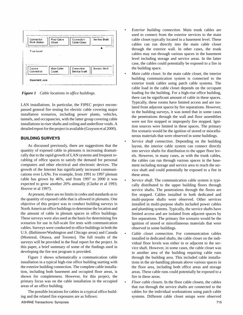
Figure 1 shows schematically a communication cableinstallation in a typical high-rise office building starting withthe exterior building connection. The complete cable installa-tion, including both basement and occupied floor areas, isshown for completeness. However, for this project, theprimary focus was on the cable installation in the occupiedareas of an office building.
The possible locations for cables in a typical office build-ing and the related fire exposures are as follows:
• Exterior building connection. Main trunk cables areused to connect from the exterior services to the maincable closet typically located in a basement level. Thesecables can run directly into the main cable closetthrough the exterior wall. In other cases, the trunkcables may run through various spaces in the basementlevel including storage and service areas. In the lattercase, the cables could potentially be exposed to a fire inthe building space.
• Main cable closet. In the main cable closet, the interiorbuilding communication system is connected to theexterior trunk cables using patch cable systems. Thecable load in the cable closet depends on the occupantloading for the building. For a high-rise office building,there can be significant amount of cable in these spaces.Typically, these rooms have limited access and are iso-lated from adjacent spaces by fire separations. However,in the building surveys, it was noted that in some casesthe penetrations through the wall and floor assemblieswere not fire stopped or improperly fire stopped. Igni-tion sources were limited in these spaces. The primaryfire scenario would be the ignition of stored or miscella-neous materials that were observed in some buildings.
• Service shaft connection. Depending on the buildinglayout, the interior cable system can connect directlyinto service shafts for distribution to the upper floor lev-els. However, in many cases, as with the trunk cables,the cables can run through various spaces in the base-ment including storage and service area to reach the ser-vice shaft and could potentially be exposed to a fire inthese areas.
• Service shaft. The communication cable system is typi-cally distributed to the upper building floors throughservice shafts. The penetrations through the floors arefire stopped. Cables installed in both dedicated andmulti-purpose shafts were observed. Other servicesinstalled in multi-purpose shafts included power cablesand plumbing systems. Typically, the service shafts havelimited access and are isolated from adjacent spaces byfire separations. The primary fire scenario would be theignition of stored or miscellaneous materials that wereobserved in some buildings.
• Cable closet connection. For communication cablesinstalled in dedicated shafts, the cable closet on the indi-vidual floor levels was either in or adjacent to the ser-vice shaft. However, in some cases, the cable closet wasin another area of the building requiring cable runsthrough the building area. This included cable installa-tions in the air-handling plenum above various spaces inthe floor area, including both office areas and storageareas. These cable runs could potentially be exposed to afire in these areas.
• Floor cable closets. In the floor cable closets, the cablesthat run through the service shafts are connected to thecables for the individual workstations using patch cablesystems. Different cable closet setups were observed
Figure 1 Cable locations in office buildings.
ASHRAE Transactions: Symposia 715
during the building surveys. In many cases, dedicatedareas in or adjacent to the service shaft were used. Typi-cally, these areas have limited access and are isolatedfrom adjacent spaces using fire rated separations. Dur-ing the building surveys, it was noted that in some casesthe penetrations through barriers were not fire stoppedor improperly fire stopped. Ignition sources were lim-ited in these areas. The primary fire scenario would bethe ignition of stored or miscellaneous materials thatwere observed in some buildings.
In other cases, the cable closet was combined with acomputer room that provided both internal and externalnetwork services. For larger computer rooms, a separateHVAC system was typically used to meet the high coolingdemands typical of such facilities. However, smaller adhoc installations were also noted, with the buildingHVAC system used for the room area. Access to thecomputer rooms is usually limited. However, there ismore day-to-day usage then in a dedicated cable closet.Also, more furnishings, including workstations, wereobserved in these spaces, increasing the fuel load.
The cables exiting the cable closets and computerrooms were rated for plenum applications. However,within the computer room, general usage cables wereused as patch cables to make the connection between thecables used in the service shafts and the cable runs to thefloor area. As a result, cables with a wide range of ratingsare present in these spaces. In the case of small ad hoccomputer rooms, cases were noted in which the patchcable connections were made through the ceiling voidspace. If the cable closet or computer rooms are notisolated from the adjacent floor areas, including theplenums used for air handling, there can potentially beconsiderable amounts of nonplenum rated cable bothinside the room and in the ceiling void. The use of nonple-num rated cable in the ceiling void space is non-code-conforming and will not be investigated as part of thisproject.
• Workstation connections. The final link in the cableinstallation is the connection from the cable closet to theindividual workstations. A single length of plenum ratedcable is typically used for this connection. In recent con-struction, cable channels are sometimes located in thebuilding floor for distributing the cables to the worksta-tions. In other cases, the cables are distributed throughthe ceiling voids. The latter is the scenario being investi-gated in this project. Of particular interest is the case inwhich the ceiling void is also used for air handling pur-poses.
The primary ignition source located in the ceiling voidspace is the electrical installations for lights and otherservices. However, in most high-density communication cableinstallations, the communication cables were run using dedi-cated systems. For example, hanger systems were mounted in
the ceiling/floor slab. In these cases, the communicationcables were isolated from the electrical systems. Also, the fireperformance for communication cable used in plenums isassessed using ignition sources with high heat output. Themore likely fire scenario that could impact on communicationcables in a plenum space is a fire in the occupied space. Thisis consistent with the fire scenarios used in the BRE full-scalefire test program (Fardell et al 1996; Fardell 1998, 2000). Thisscenario will be the focus of this project.
There are a number of fire scenarios that could involvecable installations in the basement level. However, most ofthese scenarios do not involve the ceiling void spaces that arethe subject of this study. There are exceptions where the lowestbuilding level is also occupied. In this case, the fire scenariosare similar to those on the upper floor levels. As such, the firescenarios developed for this project were based on the situa-tions found in the upper floor levels.
For occupied floor levels, two primary fire scenarios wereobserved. The scenario of particular interest was for plenumrated cables located in a plenum space with ignition from a firelocated in the space below. The second scenario was for cableslocated in a cable closet or computer room with a fire involv-ing furnishings and stored/miscellaneous items as the ignitionsource. Both of these situations will be investigated in the full-scale tests conducted for this project.
One of the main issues to be addressed with the buildingsurveys was the cable fire load in the ceiling void. A numberof previous studies have noted the potential for the buildup ofcables with the installation of new generation cables (Clarkeet al 1993; Hoover et al. 1997). However, it was determined inthis study that many building owners are having older gener-ations of cable removed, especially if major renovations of thefloor space are undertaken. An estimate of the incremental fireload for cable installations is provided in a subsequent section.
SMOKE GAS ANALYSIS
For cable fires, a measurement of the production rate ofacid gases and other smoke components is of particular inter-est. As such, FTIR spectrometers were used in conjunctionwith the tests conducted for this project.
Recently, FTIR (Fourier transform infrared) spectrome-ters are being used for smoke gas analysis (Su et al. 1998;Hakkarainen et al. 2000; Kanabus-Kaminska et al. 2001). TheFTIR spectrometric technique allows simultaneous observa-tion in real time and quantification of many volatilecompounds that have characteristic absorption bands in theinfrared region of the spectrum. This includes the majorcombustion products (CO and CO2) traditionally measured byspecialized infrared analyzers, as well as minor smoke compo-nents: hydrogen cyanide and other nitriles, acid gases andprecursors (HF, HCl, HBr, carbonyl halides, SO2, NOx), irri-tants (acrolein, formaldehyde), and hydrocarbons (methane,ethylene, acetylene).
CONE CALORIMETER TESTS
A broad range of data communication cables is availablein the North American market. Bench-scale tests wereconducted using a cone calorimeter to provide an initial eval-uation of the fire performance of representative data commu-
716 ASHRAE Transactions: Symposia
nication cables. For these tests, ten cables were purchased onthe open market. The signal transmission performance of thecables was Category 3 and Category 5. These categories ofcable have been used extensively for data communicationpurposes over the past decade or more. All the cables wereunshielded twisted pair (UTP) with four pairs of wires. Thecables were selected from the major North American manu-facturers to represent a cross section of cable types and ratingspresently used in office buildings. The cables tested includedeight that were labeled as CMP, thus meeting the requirementsfor use in air-handling plenums in the U.S. In addition, twocables were labeled as FT4, meeting the requirements forsome jurisdictions in Canada.
The bench-scale tests were conducted using the ASTME 1354 cone calorimeter (ASTM 1997) with a heat flux of50 kW/m2. Specimen mass loss and smoke production wererecorded. Any gases produced were sampled and analyzedusing standard gas analyzers for O2, CO, and CO2 to deter-mine the heat release rate. In addition, the combustion gaseswere analyzed for all ten samples using an FTIR spectrome-ter to measure other combustion by-products including HFand HCl.
For the cone tests, the cable was cut into 100 mm lengths.These cable lengths were placed side by side on a metal wiremesh in the cone calorimeter holder. An air gap was main-tained between the supporting mesh and a thermal liner on thebottom of the holder. The ends of the cables were unsealed.
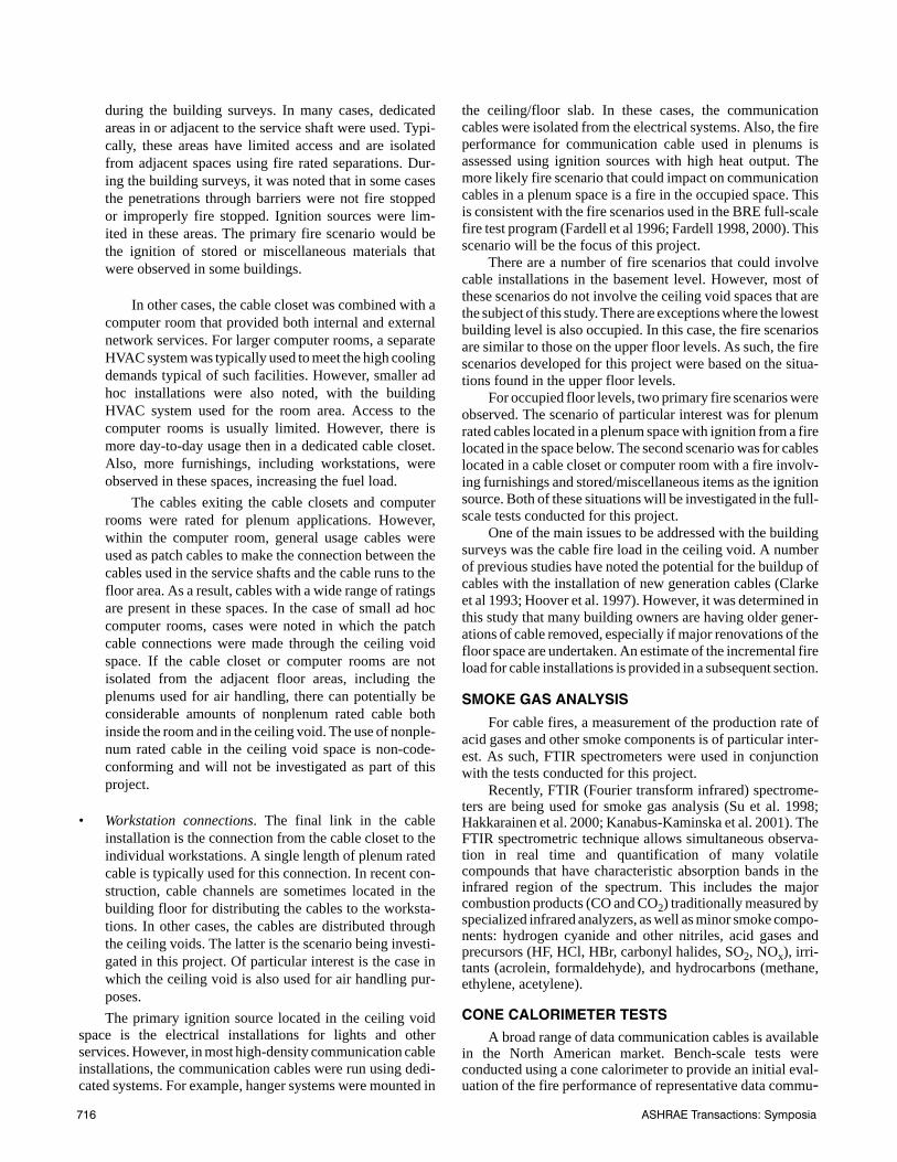
A summary of the cone calorimeter results for each cableis provided in Table 1. Each cable is referenced by a letterdesignation. The results provided in the table are the averageof three tests.
Based on an overall analysis of the cone calorimeter andFTIR results, the ten cables were grouped as three generaltypes. The jacket material for all the cables was PVC based.The insulator materials were polyolefin (Type 1—Cables B, G,H, and J), flouropolymer (Type 2—Cable C), and perfluo-ropolymer (Type 3—Cables A, D, E, F and I). There were two
Type 1cables with a CMP rating (Cables G and H) and twowith an FT4 rating (Cables B and J). There were other fillersand additives in the cable jacket and insulators that were notspecifically identified. Further results for three cables (CablesB, C, and D) that are representative of the three groups arediscussed below.
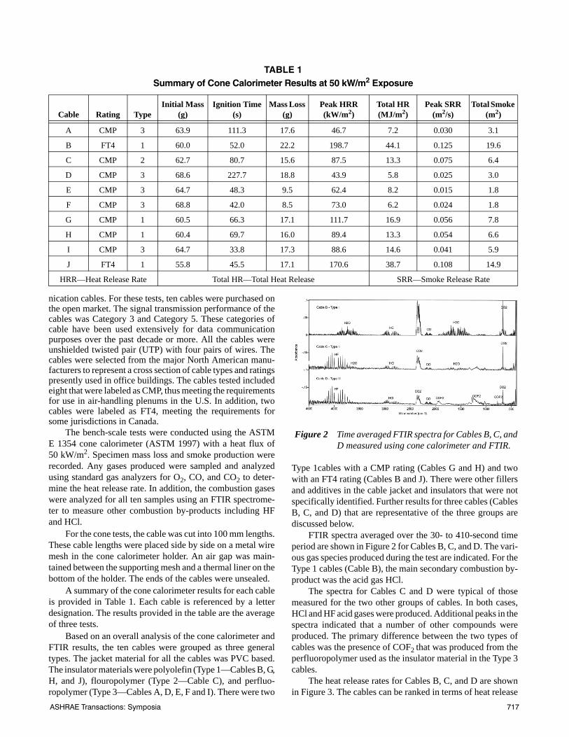
FTIR spectra averaged over the 30- to 410-second timeperiod are shown in Figure 2 for Cables B, C, and D. The vari-ous gas species produced during the test are indicated. For theType 1 cables (Cable B), the main secondary combustion by-product was the acid gas HCl.
The spectra for Cables C and D were typical of thosemeasured for the two other groups of cables. In both cases,HCl and HF acid gases were produced. Additional peaks in thespectra indicated that a number of other compounds wereproduced. The primary difference between the two types ofcables was the presence of COF2 that was produced from theperfluoropolymer used as the insulator material in the Type 3cables.
The heat release rates for Cables B, C, and D are shownin Figure 3. The cables can be ranked in terms of heat release
TABLE 1 Summary of Cone Calorimeter Results at 50 kW/m2 Exposure
Cable Rating TypeInitial Mass
(g)Ignition Time
(s)Mass Loss
(g)Peak HRR (kW/m2)
Total HR (MJ/m2)
Peak SRR (m2/s)
Total Smoke (m2)
A CMP 3 63.9 111.3 17.6 46.7 7.2 0.030 3.1
B FT4 1 60.0 52.0 22.2 198.7 44.1 0.125 19.6
C CMP 2 62.7 80.7 15.6 87.5 13.3 0.075 6.4
D CMP 3 68.6 227.7 18.8 43.9 5.8 0.025 3.0
E CMP 3 64.7 48.3 9.5 62.4 8.2 0.015 1.8
F CMP 3 68.8 42.0 8.5 73.0 6.2 0.024 1.8
G CMP 1 60.5 66.3 17.1 111.7 16.9 0.056 7.8
H CMP 1 60.4 69.7 16.0 89.4 13.3 0.054 6.6
I CMP 3 64.7 33.8 17.3 88.6 14.6 0.041 5.9
J FT4 1 55.8 45.5 17.1 170.6 38.7 0.108 14.9
HRR—Heat Release Rate Total HR—Total Heat Release SRR—Smoke Release Rate
Figure 2 Time averaged FTIR spectra for Cables B, C, andD measured using cone calorimeter and FTIR.
ASHRAE Transactions: Symposia 717
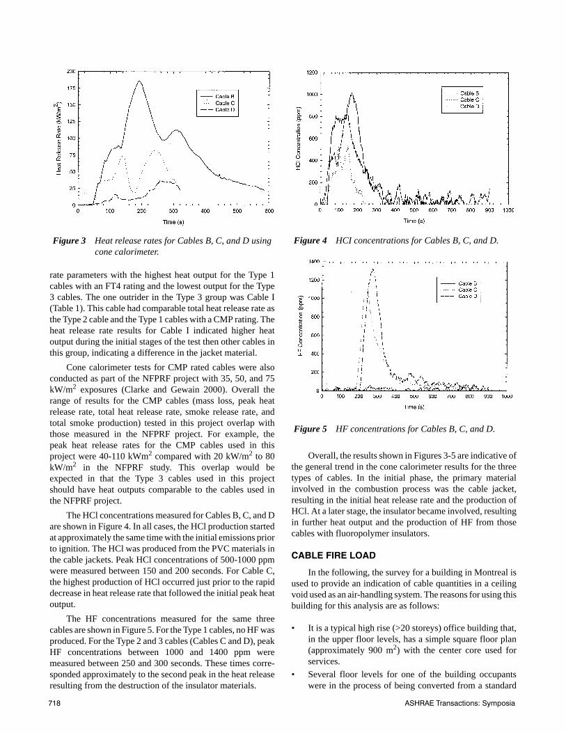
rate parameters with the highest heat output for the Type 1cables with an FT4 rating and the lowest output for the Type3 cables. The one outrider in the Type 3 group was Cable I(Table 1). This cable had comparable total heat release rate asthe Type 2 cable and the Type 1 cables with a CMP rating. Theheat release rate results for Cable I indicated higher heatoutput during the initial stages of the test then other cables inthis group, indicating a difference in the jacket material.
Cone calorimeter tests for CMP rated cables were alsoconducted as part of the NFPRF project with 35, 50, and 75kW/m2 exposures (Clarke and Gewain 2000). Overall therange of results for the CMP cables (mass loss, peak heatrelease rate, total heat release rate, smoke release rate, andtotal smoke production) tested in this project overlap withthose measured in the NFPRF project. For example, thepeak heat release rates for the CMP cables used in thisproject were 40-110 kWm2 compared with 20 kW/m2 to 80kW/m2 in the NFPRF study. This overlap would beexpected in that the Type 3 cables used in this projectshould have heat outputs comparable to the cables used inthe NFPRF project.
The HCl concentrations measured for Cables B, C, and Dare shown in Figure 4. In all cases, the HCl production startedat approximately the same time with the initial emissions priorto ignition. The HCl was produced from the PVC materials inthe cable jackets. Peak HCl concentrations of 500-1000 ppmwere measured between 150 and 200 seconds. For Cable C,the highest production of HCl occurred just prior to the rapiddecrease in heat release rate that followed the initial peak heatoutput.
The HF concentrations measured for the same threecables are shown in Figure 5. For the Type 1 cables, no HF wasproduced. For the Type 2 and 3 cables (Cables C and D), peakHF concentrations between 1000 and 1400 ppm weremeasured between 250 and 300 seconds. These times corre-sponded approximately to the second peak in the heat releaseresulting from the destruction of the insulator materials.
Overall, the results shown in Figures 3-5 are indicative ofthe general trend in the cone calorimeter results for the threetypes of cables. In the initial phase, the primary materialinvolved in the combustion process was the cable jacket,resulting in the initial heat release rate and the production ofHCl. At a later stage, the insulator became involved, resultingin further heat output and the production of HF from thosecables with fluoropolymer insulators.
CABLE FIRE LOAD
In the following, the survey for a building in Montreal isused to provide an indication of cable quantities in a ceilingvoid used as an air-handling system. The reasons for using thisbuilding for this analysis are as follows:
• It is a typical high rise (>20 storeys) office building that,in the upper floor levels, has a simple square floor plan(approximately 900 m2) with the center core used forservices.
• Several floor levels for one of the building occupantswere in the process of being converted from a standard
Figure 3 Heat release rates for Cables B, C, and D usingcone calorimeter.
Figure 4 HCI concentrations for Cables B, C, and D.
Figure 5 HF concentrations for Cables B, C, and D.
718 ASHRAE Transactions: Symposia
open plan office system to one using a high-density podsystem to increase the number of workstations on eachfloor to 100-120. This results in an increased number ofcommunication cables required on each floor level.
• These renovated floor levels were being used to house acall-in center for a major utility. Three communicationscables (one voice and two data links) were beinginstalled at each workstation. The cable length used foreach drop was typically a maximum of 95 m.
With the links to the workstations as well as other linksin the center core, approximately 400 cable drops were beinginstalled on each floor. Each cable drop was approximately45 m long, giving an estimated total cable length of 18 000 m.
Assuming a typical Category 5 communication cablewith 30 g/m, the total cable load is approximately 340 kg,giving a cable loading on the floor of 0.4 kg/m2. Based on thecone calorimeter results, the total heat output for CMP ratedcable is between 1.5 and 3 MJ/kg compared with 9-10 MJ/kgfor FT4 rated cable based on the total weight of the sample.Using these data, the specific fire load (heat content ofcombustibles/unit floor area) in the building, assuming CMPcable, is 1.2 MJ/m2 and 4.2 MJ/m2 for the FT4 cable.
The cone calorimeter results are representative of resultsfor a given fire exposure test. It does not necessarily measurethe total potential heat output for a sample. In the NFPRFstudy, the potential heat measured using a bomb calorimeter(NFPA 259) was reported for CMP rated cables (Clarke andGewain 2000). The total heat output ranged from approxi-mately 3 to 7 MJ/kg. Using these data, the contribution of thecables to the specific fire load (heat content of combustibles/unit floor area) in the building was 1.8-4.2 MJ/m2. Forcomparison, the specific fire load for the inhabited spaces in
an office building is 467 MJ/m2 (Mehaffey and Richardson1985).
The difference in heat output using NFPA 259 and thecone calorimeter is approximately a factor of 3. Using thisfactor, the estimated specific fire load for FT4 cable isapproximately 12.6 MJ/m2. For comparison, if the cables areassumed to be approximately 50% copper wire and using theheat of combustion for polyethylene (46.6 MJ/kg), the esti-mated specific fire load for FT4 cable would be approxi-mately 17.3 MJ/m2. This would suggest 12.6 MJ/m2 is arealistic estimate for the specific fire load with FT4 cable.
The specific fire load estimates provided in this sectionare based on the single generation of cables observed in thebuilding. The estimates can be extrapolated to include multi-ple generations by assuming an additional 4500 m of installedcable for each additional set of cables required for 100 drops.
MEDIUM-SCALE TESTS
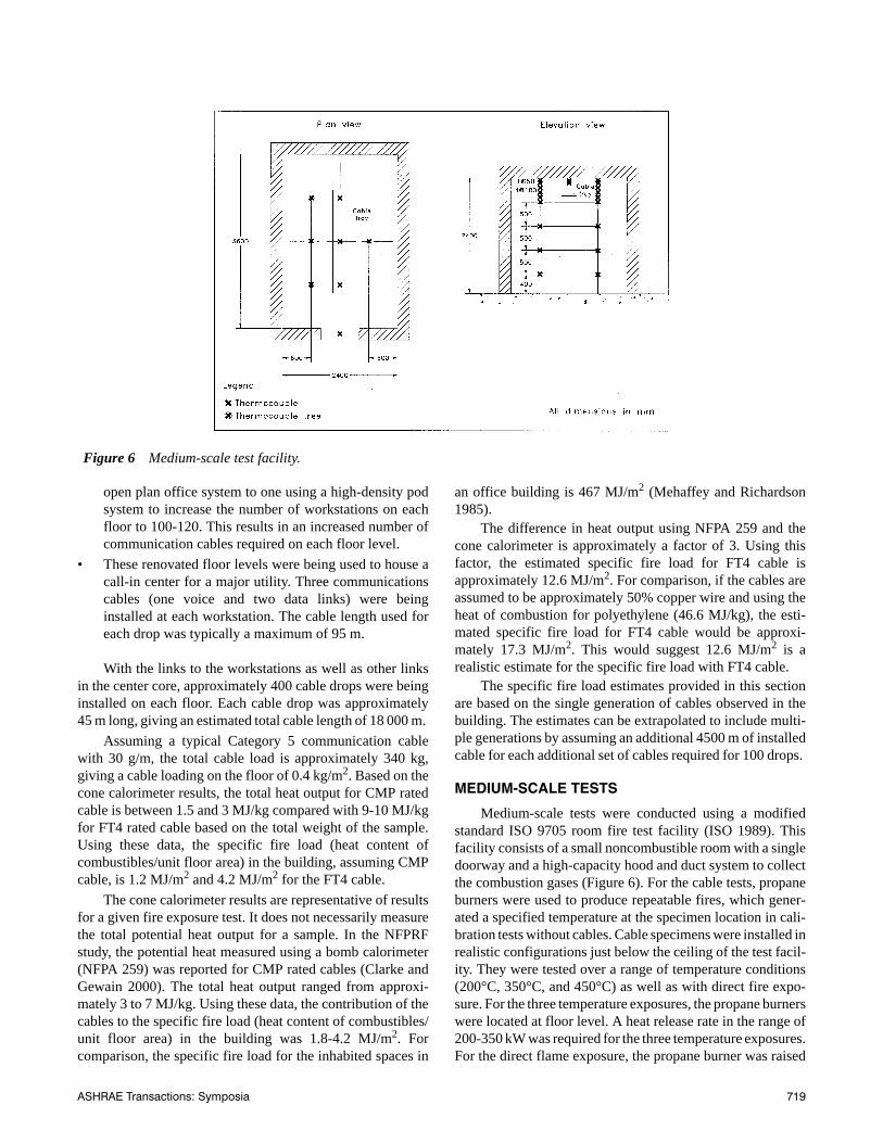
Medium-scale tests were conducted using a modifiedstandard ISO 9705 room fire test facility (ISO 1989). Thisfacility consists of a small noncombustible room with a singledoorway and a high-capacity hood and duct system to collectthe combustion gases (Figure 6). For the cable tests, propaneburners were used to produce repeatable fires, which gener-ated a specified temperature at the specimen location in cali-bration tests without cables. Cable specimens were installed inrealistic configurations just below the ceiling of the test facil-ity. They were tested over a range of temperature conditions(200°C, 350°C, and 450°C) as well as with direct fire expo-sure. For the three temperature exposures, the propane burnerswere located at floor level. A heat release rate in the range of200-350 kW was required for the three temperature exposures.For the direct flame exposure, the propane burner was raised
Figure 6 Medium-scale test facility.
ASHRAE Transactions: Symposia 719
such that the flame produced at a heat release rate of approx-imately 300 kW engulfed the cable. The test duration wasbetween 15 and 30 minutes with the longer exposures typi-cally used for the tests at lower temperatures.
Measurements included mass loss rate, smoke produc-tion, and heat release rates. In addition, gas samples weretaken from the room exhaust duct and analyzed using bothstandard gas analyzers and the FTIR.
One objective of these tests was to determine the behaviorof the communication cables under a range of simulated fireconditions. In particular, the tests were designed to investigatethe thermal degradation of the cables under a range of thermalconditions that could occur for fires in the occupied area of anoffice building. In this case, the hot gases would enter the ceil-ing void space exposing the communication cable to elevatedtemperatures. The exposure temperatures will depend onwhether the occupied area is sprinklered.
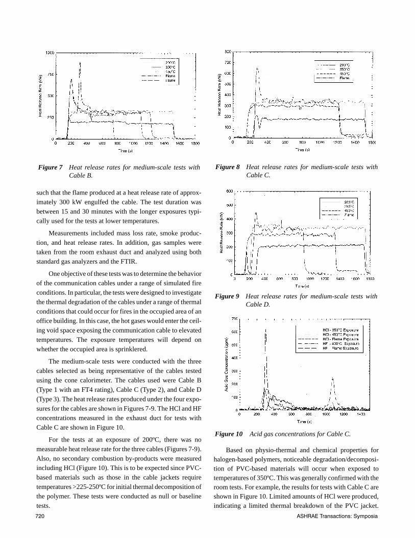
The medium-scale tests were conducted with the threecables selected as being representative of the cables testedusing the cone calorimeter. The cables used were Cable B(Type 1 with an FT4 rating), Cable C (Type 2), and Cable D(Type 3). The heat release rates produced under the four expo-sures for the cables are shown in Figures 7-9. The HCl and HFconcentrations measured in the exhaust duct for tests withCable C are shown in Figure 10.
For the tests at an exposure of 200ºC, there was nomeasurable heat release rate for the three cables (Figures 7-9).Also, no secondary combustion by-products were measuredincluding HCl (Figure 10). This is to be expected since PVC-based materials such as those in the cable jackets requiretemperatures >225-250ºC for initial thermal decomposition ofthe polymer. These tests were conducted as null or baselinetests.
Based on physio-thermal and chemical properties forhalogen-based polymers, noticeable degradation/decomposi-tion of PVC-based materials will occur when exposed totemperatures of 350ºC. This was generally confirmed with theroom tests. For example, the results for tests with Cable C areshown in Figure 10. Limited amounts of HCl were produced,indicating a limited thermal breakdown of the PVC jacket.
Figure 7 Heat release rates for medium-scale tests withCable B.
Figure 8 Heat release rates for medium-scale tests withCable C.
Figure 9 Heat release rates for medium-scale tests withCable D.
Figure 10 Acid gas concentrations for Cable C.
720 ASHRAE Transactions: Symposia
However, there was no HF production to indicate a breakdownof the fluoropolymer insulator. Also, for all cables, there wasno measurable heat release rate (Figures 7-9).
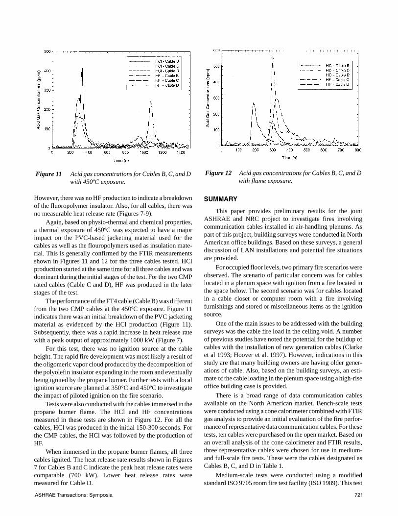
Again, based on physio-thermal and chemical properties,a thermal exposure of 450ºC was expected to have a majorimpact on the PVC-based jacketing material used for thecables as well as the flouropolymers used as insulation mate-rial. This is generally confirmed by the FTIR measurementsshown in Figures 11 and 12 for the three cables tested. HClproduction started at the same time for all three cables and wasdominant during the initial stages of the test. For the two CMPrated cables (Cable C and D), HF was produced in the laterstages of the test.
The performance of the FT4 cable (Cable B) was differentfrom the two CMP cables at the 450ºC exposure. Figure 11indicates there was an initial breakdown of the PVC jacketingmaterial as evidenced by the HCl production (Figure 11).Subsequently, there was a rapid increase in heat release ratewith a peak output of approximately 1000 kW (Figure 7).
For this test, there was no ignition source at the cableheight. The rapid fire development was most likely a result ofthe oligomeric vapor cloud produced by the decomposition ofthe polyolefin insulator expanding in the room and eventuallybeing ignited by the propane burner. Further tests with a localignition source are planned at 350°C and 450ºC to investigatethe impact of piloted ignition on the fire scenario.
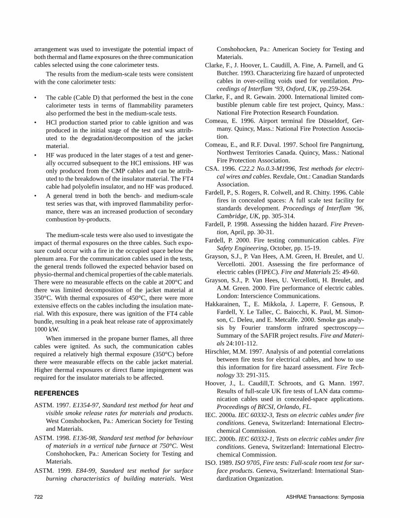
Tests were also conducted with the cables immersed in thepropane burner flame. The HCl and HF concentrationsmeasured in these tests are shown in Figure 12. For all thecables, HCl was produced in the initial 150-300 seconds. Forthe CMP cables, the HCl was followed by the production ofHF.
When immersed in the propane burner flames, all threecables ignited. The heat release rate results shown in Figures7 for Cables B and C indicate the peak heat release rates werecomparable (700 kW). Lower heat release rates weremeasured for Cable D.
SUMMARY
This paper provides preliminary results for the jointASHRAE and NRC project to investigate fires involvingcommunication cables installed in air-handling plenums. Aspart of this project, building surveys were conducted in NorthAmerican office buildings. Based on these surveys, a generaldiscussion of LAN installations and potential fire situationsare provided.
For occupied floor levels, two primary fire scenarios wereobserved. The scenario of particular concern was for cableslocated in a plenum space with ignition from a fire located inthe space below. The second scenario was for cables locatedin a cable closet or computer room with a fire involvingfurnishings and stored or miscellaneous items as the ignitionsource.
One of the main issues to be addressed with the buildingsurveys was the cable fire load in the ceiling void. A numberof previous studies have noted the potential for the buildup ofcables with the installation of new generation cables (Clarkeet al 1993; Hoover et al. 1997). However, indications in thisstudy are that many building owners are having older gener-ations of cable. Also, based on the building surveys, an esti-mate of the cable loading in the plenum space using a high-riseoffice building case is provided.
There is a broad range of data communication cablesavailable on the North American market. Bench-scale testswere conducted using a cone calorimeter combined with FTIRgas analysis to provide an initial evaluation of the fire perfor-mance of representative data communication cables. For thesetests, ten cables were purchased on the open market. Based onan overall analysis of the cone calorimeter and FTIR results,three representative cables were chosen for use in medium-and full-scale fire tests. These were the cables designated asCables B, C, and D in Table 1.
Medium-scale tests were conducted using a modifiedstandard ISO 9705 room fire test facility (ISO 1989). This test
Figure 11 Acid gas concentrations for Cables B, C, and Dwith 450ºC exposure.
Figure 12 Acid gas concentrations for Cables B, C, and Dwith flame exposure.
ASHRAE Transactions: Symposia 721
arrangement was used to investigate the potential impact ofboth thermal and flame exposures on the three communicationcables selected using the cone calorimeter tests.
The results from the medium-scale tests were consistentwith the cone calorimeter tests:
• The cable (Cable D) that performed the best in the conecalorimeter tests in terms of flammability parametersalso performed the best in the medium-scale tests.
• HCl production started prior to cable ignition and wasproduced in the initial stage of the test and was attrib-uted to the degradation/decomposition of the jacketmaterial.
• HF was produced in the later stages of a test and gener-ally occurred subsequent to the HCl emissions. HF wasonly produced from the CMP cables and can be attrib-uted to the breakdown of the insulator material. The FT4cable had polyolefin insulator, and no HF was produced.
• A general trend in both the bench- and medium-scaletest series was that, with improved flammability perfor-mance, there was an increased production of secondarycombustion by-products.
The medium-scale tests were also used to investigate theimpact of thermal exposures on the three cables. Such expo-sure could occur with a fire in the occupied space below theplenum area. For the communication cables used in the tests,the general trends followed the expected behavior based onphysio-thermal and chemical properties of the cable materials.There were no measurable effects on the cable at 200°C andthere was limited decomposition of the jacket material at350°C. With thermal exposures of 450°C, there were moreextensive effects on the cables including the insulation mate-rial. With this exposure, there was ignition of the FT4 cablebundle, resulting in a peak heat release rate of approximately1000 kW.
When immersed in the propane burner flames, all threecables were ignited. As such, the communication cablesrequired a relatively high thermal exposure (350°C) beforethere were measurable effects on the cable jacket material.Higher thermal exposures or direct flame impingement wasrequired for the insulator materials to be affected.
REFERENCES
ASTM. 1997. E1354-97, Standard test method for heat andvisible smoke release rates for materials and products.West Conshohocken, Pa.: American Society for Testingand Materials.
ASTM. 1998. E136-98, Standard test method for behaviourof materials in a vertical tube furnace at 750°C. WestConshohocken, Pa.: American Society for Testing andMaterials.
ASTM. 1999. E84-99, Standard test method for surfaceburning characteristics of building materials. West
Conshohocken, Pa.: American Society for Testing andMaterials.
Clarke, F., J. Hoover, L. Caudill, A. Fine, A. Parnell, and G.Butcher. 1993. Characterizing fire hazard of unprotectedcables in over-ceiling voids used for ventilation. Pro-ceedings of Interflam ‘93, Oxford, UK, pp.259-264.
Clarke, F., and R. Gewain. 2000. International limited com-bustible plenum cable fire test project, Quincy, Mass.:National Fire Protection Research Foundation.
Comeau, E. 1996. Airport terminal fire Düsseldorf, Ger-many. Quincy, Mass.: National Fire Protection Associa-tion.
Comeau, E., and R.F. Duval. 1997. School fire Pangnirtung,Northwest Territories Canada. Quincy, Mass.: NationalFire Protection Association.
CSA. 1996. C22.2 No.0.3-M1996, Test methods for electri-cal wires and cables. Rexdale, Ont.: Canadian StandardsAssociation.
Fardell, P., S. Rogers, R. Colwell, and R. Chitty. 1996. Cablefires in concealed spaces: A full scale test facility forstandards development. Proceedings of Interflam ‘96,Cambridge, UK, pp. 305-314.
Fardell, P. 1998. Assessing the hidden hazard. Fire Preven-tion, April, pp. 30-31.
Fardell, P. 2000. Fire testing communication cables. FireSafety Engineering, October, pp. 15-19.
Grayson, S.J., P. Van Hees, A.M. Green, H. Breulet, and U.Vercellotti. 2001. Assessing the fire performance ofelectric cables (FIPEC). Fire and Materials 25: 49-60.
Grayson, S.J., P. Van Hees, U. Vercellotti, H. Breulet, andA.M. Green. 2000. Fire performance of electric cables.London: Interscience Communications.
Hakkarainen, T., E. Mikkola, J. Laperre, F. Gensous, P.Fardell, Y. Le Tallec, C. Baiocchi, K. Paul, M. Simon-son, C. Deleu, and E. Metcalfe. 2000. Smoke gas analy-sis by Fourier transform infrared spectroscopy—Summary of the SAFIR project results. Fire and Materi-als 24:101-112.
Hirschler, M.M. 1997. Analysis of and potential correlationsbetween fire tests for electrical cables, and how to usethis information for fire hazard assessment. Fire Tech-nology 33: 291-315.
Hoover, J., L. Caudill,T. Schroots, and G. Mann. 1997.Results of full-scale UK fire tests of LAN data commu-nication cables used in concealed-space applications.Proceedings of BICSI, Orlando, FL.
IEC. 2000a. IEC 60332-3, Tests on electric cables under fireconditions. Geneva, Switzerland: International Electro-chemical Commission.
IEC. 2000b. IEC 60332-1, Tests on electric cables under fireconditions. Geneva, Switzerland: International Electro-chemical Commission.
ISO. 1989. ISO 9705, Fire tests: Full-scale room test for sur-face products. Geneva, Switzerland: International Stan-dardization Organization.
722 ASHRAE Transactions: Symposia

Kanabus-Kaminska, M., G.D. Lougheed, D.W. Carpenter,and D.A. Torvi. 2001. Determination of major andminor components of smoke from full-scale fire tests offurnishings by FTIR spectroscopy. Fire and Materials,San Francisco, pp. 407-417.
Mehaffey, J., and J. Richardson. 1985. Electrical cables: Aless significant factor in fire. Canadian ConsultingEngineer, Vol. 27.
NFPA. 1996. NFPA 255, Standard method of test of surfaceburning characteristics of building materials. Quincy,Mass.: National Fire Protection Association.
NFPA. 1998. NFPA 259, Standard test method for potentialheat of building materials. Quincy, Mass.: National FireProtection Association.
NFPA. 1999a. NFPA 13, Installation of sprinkler systems.Quincy, Mass.: National Fire Protection Association.
NFPA. 1999b. NFPA 262, Standard method of test for fireand smoke characteristics of wires and cables. Quincy,Mass.: National Fire Protection Association.
NFPA. 1999c. NFPA 90A, Standard for the installation of airconditioning and ventilating systems. Quincy, Mass.:National Fire Protection Association.
NFPA. 1996c. NFPA 70, National electric code. Quincy,Mass.: National Fire Protection Association.
NRC. 1995. National building code of Canada. Ottawa,Ont.: National Research Council of Canada.
Przybyla, L., E. Coffey, S. Kaufman, M. Yocum, J. Reed,and D. Allen. 1981. Low smoke and flame spreadcables. Journal of Fire and Flammability 12: 177-199.
Su, J.Z., A.K. Kim, and J.M. Kanabus-Kaminska. 1998.FTIR spectroscopic measurement of halogenated com-pounds produced during fire suppression tests of twohalon replacements. Fire Safety Journal 31: 1-17.
UL. 1997a. UL1581, Reference standard for electrical wires,cables, flexible cords, 1160. Northbrook, Ill.: Under-writers Laboratories.
UL. 1997b. UL1581, Reference standard for electrical wires,cables, flexible cords, 1080. Northbrook, Ill.: Under-writers Laboratories.
UL. 1998. UL 910, Test for flame-propagation and smoke-density values for electrical and optical-fiber cablesused in spaces transporting environmental air. North-brook, Ill.: Underwriters Laboratories.
UL. 2000. UL 1666, Test for flame propagation height ofelectrical and optical-fiber cables installed vertically inshafts. Northbrook, Ill.: Underwriters Laboratories.
ULC. 1980. CAN4-S114-M80, Test for determination of non-combustibility in building materials. Scarborough, Ont.:Underwriters’ Laboratories of Canada.
ULC. 1987. ULC-S102.4-1987, Test for fire and smoke char-acteristics of electrical wiring and cable. Scarborough,Ont.: Underwriters’ Laboratories of Canada.
DISCUSSION
James S. Buckley, Principal, CCRD Partners, Houston,TX: Did the research tests include any limited combustiblecables, as defined by NDPA 90A?Gary Lougheed: The test program did not include anylimited combustible cables, as defined by NFPA 90A.
ASHRAE Transactions: Symposia 723