Embed Size (px)
Citation preview
Initial Evaluation of Advanced Powder Metallurgy Magnesium Alloys for Dynamic Applications
Tyrone Jones1, Katsuyoshi Kondoh2 1 U.S. Army Research Laboratory; AMSRD-ARL-WM-TA, APG, MD 21005 USA
2 Joining and Welding Research Institute, Osaka University; 11-1 Mihogaoka, Ibaraki 567-0047 OSAKA, JAPAN
Keywords: Powder Metallurgy, Magnesium Alloys, AZ31B, AMX602, Ballistic Performance, Structural
Abstract
The U.S. Army Research Laboratory (ARL) is interested in
assessing the performance of different magnesium alloys. The
ARL and the Joining and Welding Research Institute (JWRI)
conducted a joint effort to develop and evaluate advanced powder
metallurgy magnesium alloys AZ31B and AMX602 (Mg-6Al-
0.5Mn-2Ca/mass%) sheets. JWRI performed the mechanical and
metallurgical analysis, while ARL performed the ballistic
analysis. The thin gauge magnesium alloy sheets were ballistically
evaluated against the 0.22-cal fragment simulating projectile
(FSP). The powder magnesium alloys’ mechanical properties and
ballistic performance are compared to the conventionally
processed AZ31B-H24.
Introduction
The ballistic evaluation of conventionally rolled AZ31B-H24
plate has given the armor community a baseline of how it
compares to 5083-H131AL aluminum alloy [1]. Powder
metallurgy (P/M) process is effective to control the microstructure
by refining grains and intermetallics, and producing non-
equilibrium alloy compositions of metals [2]. In particular, rapid
solidification process by atomization is often used to prepare raw
powders with ultra-fine microstructures. In this study, a water-
atomization process is applied to produce coarse magnesium alloy
powders with fine grains and intermetallic compounds [3]. They
are consolidated by the conventional P/M process such as cold
compaction, spark plasma sintering, and hot extrusion process.
The microstructures, static and ballistic properties of P/M wrought
magnesium alloys are evaluated, and the effects of alloy elements
and microstructures on their properties are discussed in detail.
Powder Metallurgy
Two kinds of magnesium alloy powder produced by water-
atomization process were prepared in this study; AZ31B (Mg-
3Al-1Zn-0.3Mn/mass%) and AMX602 (Mg-6Al-0.5Mn-
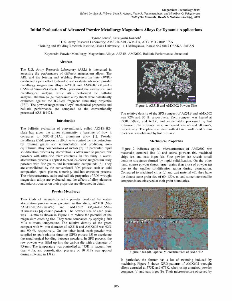
2Ca/mass%) [4] coarse powders. The powder size of each grain
was 1~4-mm as shown in Figure 1 to reduce the potential of the
magnesium catching fire. They were compacted by applying 300
MPa at room temperature. The relative density of the green
compact with 94-mm diameter of AZ31B and AMX602 was 92%
and 90 %, respectively. On the other hand, each powder was
supplied to spark plasma sintering (SPS) process [5] to accelerate
the metallurgical bonding between powders. In SPS process, the
raw powder was filled up into the carbon die with a diameter of
95-mm. The temperature was controlled at 473K in vacuum less
than 4 Pa, and consolidation pressure of 10 MPa was applied
during sintering in 1.8 ks.
Figure 1. AZ31B and AMX602 Powder Size
The relative density of the SPS compact of AZ31B and AMX602
was 72% and 70 %, respectively. Each compact was heated at
573K, 598K, and 623K, and immediately processed by hot
extrusion. The extrusion ratio and speed was 40 and 50 mm/s,
respectively. The plate specimen with 40 mm width and 5 mm
thickness was obtained by hot extrusion.
Mechanical Properties
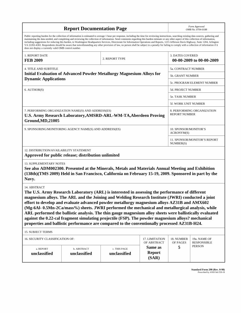
Figure 2 indicates optical microstructures of AMX602 raw
materials; atomized fine (a) and coarse powders (b), machined
chips (c), and cast ingot (d). Fine powder (a) reveals small
dendrite structures formed by rapid solidification. On the other
hand, coarse powder shows larger grains than those of powder (a)
due to the smaller solidification ration during atomization.
Compared to machined chips (c) and cast material (d), they have
the almost same grain size of 60~150μm, and some intermetallic
compounds are observed at their grain boundaries.
Figure 2 (a)-(d). Optical Microstructures of AMX602
In particular, the former has a lot of twinning induced by
machining. Figure 3 shows XRD patterns of AMX602 wrought
alloys extruded at 573K and 673K, when using atomized powder
compacts (a) and cast ingot (b). Their microstructure observed by
185
Magnesium Technology 2009 Edited by: Eric A. Nyberg, Sean R. Agnew, Neale R. Neelameggham, and Mihriban O. Pekguleryuz
TMS (The Minerals, Metals & Materials Society), 2009
Report Documentation Page Form ApprovedOMB No. 0704-0188
Public reporting burden for the collection of information is estimated to average 1 hour per response, including the time for reviewing instructions, searching existing data sources, gathering andmaintaining the data needed, and completing and reviewing the collection of information. Send comments regarding this burden estimate or any other aspect of this collection of information,including suggestions for reducing this burden, to Washington Headquarters Services, Directorate for Information Operations and Reports, 1215 Jefferson Davis Highway, Suite 1204, ArlingtonVA 22202-4302. Respondents should be aware that notwithstanding any other provision of law, no person shall be subject to a penalty for failing to comply with a collection of information if itdoes not display a currently valid OMB control number.
1. REPORT DATE FEB 2009 2. REPORT TYPE
3. DATES COVERED 00-00-2009 to 00-00-2009
4. TITLE AND SUBTITLE Initial Evaluation of Advanced Powder Metallurgy Magnesium Alloys forDynamic Applications
5a. CONTRACT NUMBER
5b. GRANT NUMBER
5c. PROGRAM ELEMENT NUMBER
6. AUTHOR(S) 5d. PROJECT NUMBER
5e. TASK NUMBER
5f. WORK UNIT NUMBER
7. PERFORMING ORGANIZATION NAME(S) AND ADDRESS(ES) U.S. Army Research Laboratory,AMSRD-ARL-WM-TA,Aberdeen Proving Ground,MD,21005
8. PERFORMING ORGANIZATIONREPORT NUMBER
9. SPONSORING/MONITORING AGENCY NAME(S) AND ADDRESS(ES) 10. SPONSOR/MONITOR’S ACRONYM(S)
11. SPONSOR/MONITOR’S REPORT NUMBER(S)
12. DISTRIBUTION/AVAILABILITY STATEMENT Approved for public release; distribution unlimited
13. SUPPLEMENTARY NOTES See also ADM002300. Presented at the Minerals, Metals and Materials Annual Meeting and Exhibition(138th)(TMS 2009) Held in San Francisco, California on February 15-19, 2009. Sponsored in part by the Navy.
14. ABSTRACT The U.S. Army Research Laboratory (ARL) is interested in assessing the performance of differentmagnesium alloys. The ARL and the Joining and Welding Research Institute (JWRI) conducted a jointeffort to develop and evaluate advanced powder metallurgy magnesium alloys AZ31B and AMX602(Mg-6Al- 0.5Mn-2Ca/mass%) sheets. JWRI performed the mechanical and metallurgical analysis, whileARL performed the ballistic analysis. The thin gauge magnesium alloy sheets were ballistically evaluatedagainst the 0.22-cal fragment simulating projectile (FSP). The powder magnesium alloys? mechanicalproperties and ballistic performance are compared to the conventionally processed AZ31B-H24.
15. SUBJECT TERMS
16. SECURITY CLASSIFICATION OF: 17. LIMITATIONOF ABSTRACT
Same asReport (SAR)
18. NUMBEROF PAGES
5
19a. NAME OFRESPONSIBLE PERSON
a. REPORT unclassified
b. ABSTRACT unclassified
c. THIS PAGE unclassified
Standard Form 298 (Rev. 8-98) Prescribed by ANSI Std Z39-18
SEM are shown In Figure 4, where (a) and (b) indicate the powder
compacts and cast ingot, respectively. When employing atomized
powders, the fine grains via dynamic recrystallization are
observed. The lower extrusion temperature at 573K is effective to
form the finer microstructures with a mean grains size of
0.45-micomemeters, which is measured by applying the image
scanning soft ware to the SEM photo. Very fine white particles
are Al2Ca compounds precipitated during heating before hot
extrusion.
Figure 3. X-Ray Diffractions of AMX602: atomized powder
compacts (a) & cast ingot (b)
Figure 4. Scanning Electron Microscope of AMX602
In the case of cast ingots (b), the mean grain size of extruded
materials at 573 K and 673 K is 1.96μm and 3.29μm,
respectively. The higher heating temperature causes the grain
coarsening. Both wrought alloys using AMX602 cast ingots
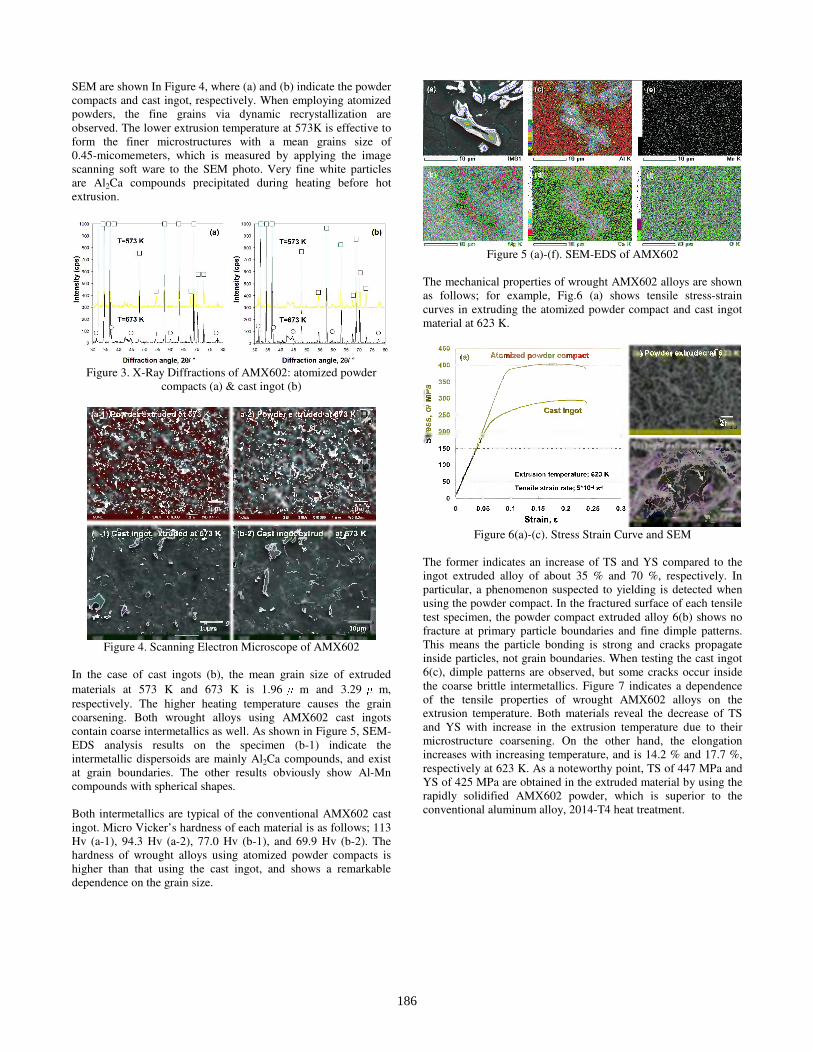
contain coarse intermetallics as well. As shown in Figure 5, SEM-
EDS analysis results on the specimen (b-1) indicate the
intermetallic dispersoids are mainly Al2Ca compounds, and exist
at grain boundaries. The other results obviously show Al-Mn
compounds with spherical shapes.
Both intermetallics are typical of the conventional AMX602 cast
ingot. Micro Vicker’s hardness of each material is as follows; 113
Hv (a-1), 94.3 Hv (a-2), 77.0 Hv (b-1), and 69.9 Hv (b-2). The
hardness of wrought alloys using atomized powder compacts is
higher than that using the cast ingot, and shows a remarkable
dependence on the grain size.
Figure 5 (a)-(f). SEM-EDS of AMX602
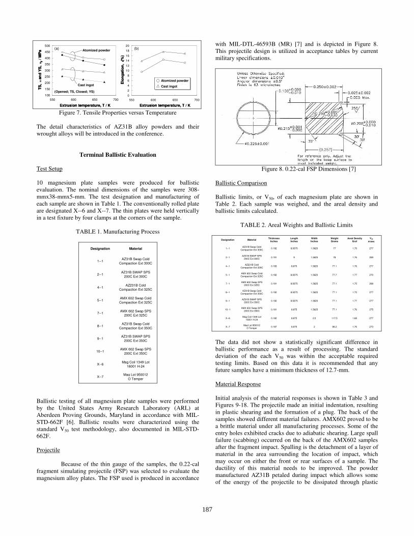
The mechanical properties of wrought AMX602 alloys are shown
as follows; for example, Fig.6 (a) shows tensile stress-strain
curves in extruding the atomized powder compact and cast ingot
material at 623 K.
Figure 6(a)-(c). Stress Strain Curve and SEM
The former indicates an increase of TS and YS compared to the
ingot extruded alloy of about 35 % and 70 %, respectively. In
particular, a phenomenon suspected to yielding is detected when
using the powder compact. In the fractured surface of each tensile
test specimen, the powder compact extruded alloy 6(b) shows no
fracture at primary particle boundaries and fine dimple patterns.
This means the particle bonding is strong and cracks propagate
inside particles, not grain boundaries. When testing the cast ingot
6(c), dimple patterns are observed, but some cracks occur inside
the coarse brittle intermetallics. Figure 7 indicates a dependence
of the tensile properties of wrought AMX602 alloys on the
extrusion temperature. Both materials reveal the decrease of TS
and YS with increase in the extrusion temperature due to their
microstructure coarsening. On the other hand, the elongation
increases with increasing temperature, and is 14.2 % and 17.7 %,
respectively at 623 K. As a noteworthy point, TS of 447 MPa and
YS of 425 MPa are obtained in the extruded material by using the
rapidly solidified AMX602 powder, which is superior to the
conventional aluminum alloy, 2014-T4 heat treatment.
186
0
2
4
6
8
10
12
14
16
18
20
550 600 650 700
Extrusion temperature, T / K
Elo
ng
ati
on
,
εεεε(%)Atomized powder
Cast ingot
(b)
0
2
4
6
8
10
12
14
16
18
20
550 600 650 700
Extrusion temperature, T / K
Elo
ng
ati
on
,
εεεε(%)Atomized powder
Cast ingot
Atomized powder
Cast ingot
(b)
100
150
200
250
300
350
400
450
500
550 600 650 700
TS
,
σσσσand YS, σσσσy/ MPaExtrusion temperature, T / K
Atomized powder
Cast ingot
(Opened; TS, Closed; YS)
(a)
100
150
200
250
300
350
400
450
500
550 600 650 700
TS
,
σσσσand YS, σσσσy/ MPaExtrusion temperature, T / K
Atomized powder
Cast ingot
(Opened; TS, Closed; YS)
(a)
Figure 7. Tensile Properties versus Temperature
The detail characteristics of AZ31B alloy powders and their
wrought alloys will be introduced in the conference.
Terminal Ballistic Evaluation
Test Setup
10 magnesium plate samples were produced for ballistic
evaluation. The nominal dimensions of the samples were 308-
mmx38-mmx5-mm. The test designation and manufacturing of
each sample are shown in Table 1. The conventionally rolled plate
are designated X--6 and X--7. The thin plates were held vertically
in a test fixture by four clamps at the corners of the sample.
TABLE 1. Manufacturing Process
Designation Material
1--1AZ31B Swap Cold
Compaction Ext 300C
2--1AZ31B SWAP SPS
200C Ext 300C
4--1AZ231B Cold
Compaction Ext 325C
5--1AMX 602 Swap Cold
Compaction Ext 325C
7--1AMX 602 Swap SPS
200C Ext 325C
8--1AZ31B Swap Cold
Compaction Ext 350C
9--1AZ31B SWAP SPS
200C Ext 350C
10--1AMX 602 Swap SPS
200C Ext 350C
X--6Mag Coil 1349 Lot
16001 H-24
X--7Mag Lot 950012
O Temper
Ballistic testing of all magnesium plate samples were performed
by the United States Army Research Laboratory (ARL) at
Aberdeen Proving Grounds, Maryland in accordance with MIL-
STD-662F [6]. Ballistic results were characterized using the
standard V50 test methodology, also documented in MIL-STD-
662F.
Projectile
Because of the thin gauge of the samples, the 0.22-cal
fragment simulating projectile (FSP) was selected to evaluate the
magnesium alloy plates. The FSP used is produced in accordance
with MIL-DTL-46593B (MR) [7] and is depicted in Figure 8.
This projectile design is utilized in acceptance tables by current
military specifications.
Figure 8. 0.22-cal FSP Dimensions [7]
Ballistic Comparison
Ballistic limits, or V50, of each magnesium plate are shown in
Table 2. Each sample was weighed, and the areal density and
ballistic limits calculated.
TABLE 2. Areal Weights and Ballistic Limits
Designation Material
Thickness
Inches
Length
Inches
Width
Inches
Weight
Grams
Aeral Density
lb/sf
V50
m/sec
1--1AZ31B Swap Cold
Compaction Ext 300C0.192 8.9375 1.5625 77 1.75 277
2--1AZ31B SWAP SPS
200C Ext 300C 0.191 9 1.5625 78 1.76 269
4--1AZ231B Cold
Compaction Ext 325C0.193 8.875 1.5625 77.1 1.76 277
5--1AMX 602 Swap Cold
Compaction Ext 325C 0.192 8.9375 1.5625 77.7 1.77 270
7--1AMX 602 Swap SPS
200C Ext 325C0.191 8.9375 1.5625 77.1 1.75 268
8--1AZ31B Swap Cold
Compaction Ext 350C0.192 8.9375 1.5625 77.1 1.75 277
9--1AZ31B SWAP SPS
200C Ext 350C 0.192 8.9375 1.5625 77.1 1.77 277
10--1AMX 602 Swap SPS
200C Ext 350C0.191 8.875 1.5625 77.1 1.76 275
X--6Mag Coil 1349 Lot
16001 H-240.182 8.875 2.5 117.5 1.68 277
X--7Mag Lot 950012
O Temper0.187 8.875 2 98.2 1.76 273
The data did not show a statistically significant difference in
ballistic performance as a result of processing. The standard
deviation of the each V50 was within the acceptable required
testing limits. Based on this data it is recommended that any
future samples have a minimum thickness of 12.7-mm.
Material Response
Initial analysis of the material responses is shown in Table 3 and
Figures 9-18. The projectile made an initial indentation, resulting
in plastic shearing and the formation of a plug. The back of the
samples showed different material failures. AMX602 proved to be
a brittle material under all manufacturing processes. Some of the
entry holes exhibited cracks due to adiabatic shearing. Large spall
failure (scabbing) occurred on the back of the AMX602 samples
after the fragment impact. Spalling is the detachment of a layer of
material in the area surrounding the location of impact, which
may occur on either the front or rear surfaces of a sample. The
ductility of this material needs to be improved. The powder
manufactured AZ31B petaled during impact which allows some
of the energy of the projectile to be dissipated through plastic
187
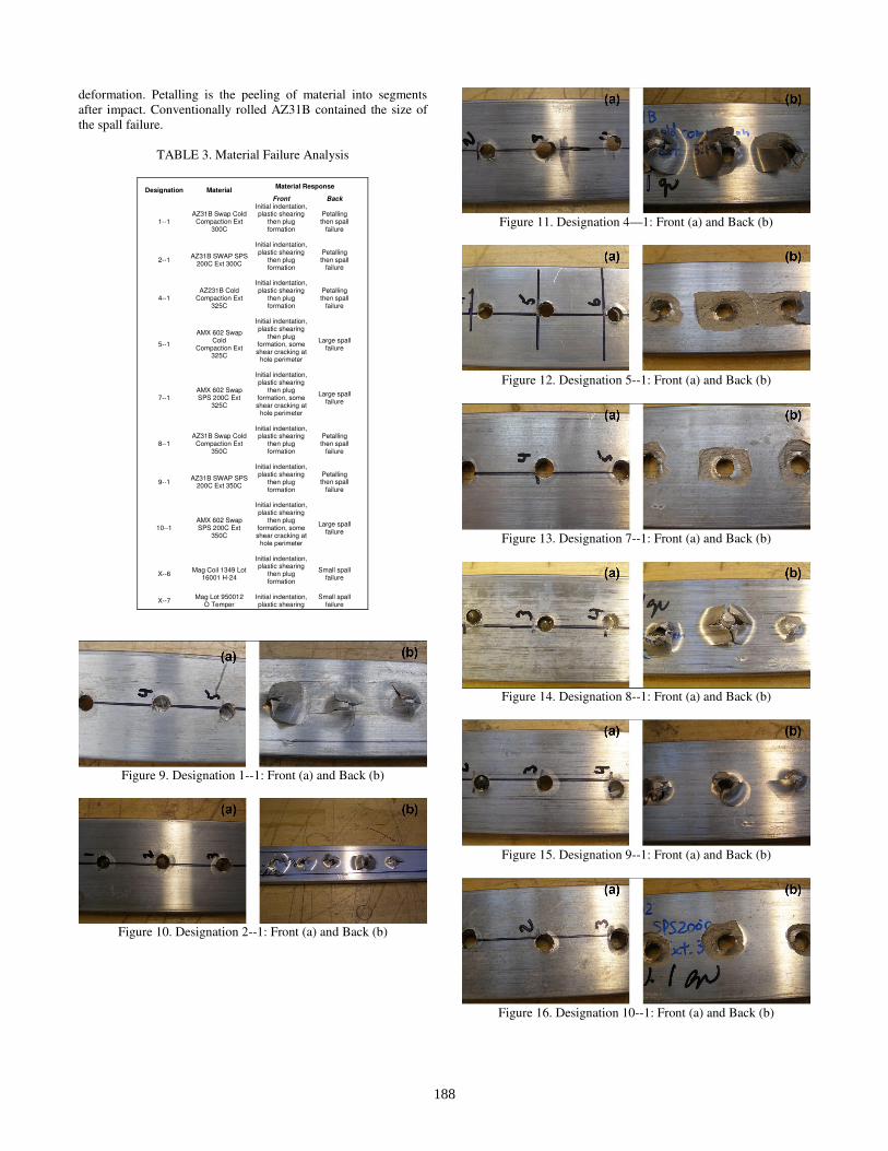
deformation. Petalling is the peeling of material into segments
after impact. Conventionally rolled AZ31B contained the size of
the spall failure.
TABLE 3. Material Failure Analysis
Material Response
Designation Material
Front Back
1--1 AZ31B Swap Cold
Compaction Ext 300C
Initial indentation, plastic shearing
then plug formation
Petalling then spall
failure
2--1 AZ31B SWAP SPS
200C Ext 300C
Initial indentation, plastic shearing
then plug formation
Petalling then spall
failure
4--1 AZ231B Cold
Compaction Ext 325C
Initial indentation, plastic shearing
then plug formation
Petalling then spall
failure
5--1
AMX 602 Swap Cold
Compaction Ext 325C
Initial indentation, plastic shearing
then plug formation, some shear cracking at
hole perimeter
Large spall failure
7--1 AMX 602 Swap SPS 200C Ext
325C
Initial indentation, plastic shearing
then plug formation, some shear cracking at
hole perimeter
Large spall failure
8--1 AZ31B Swap Cold
Compaction Ext 350C
Initial indentation, plastic shearing
then plug formation
Petalling then spall
failure
9--1 AZ31B SWAP SPS
200C Ext 350C
Initial indentation, plastic shearing
then plug formation
Petalling then spall
failure
10--1 AMX 602 Swap SPS 200C Ext
350C
Initial indentation, plastic shearing
then plug formation, some shear cracking at
hole perimeter
Large spall failure
X--6 Mag Coil 1349 Lot
16001 H-24
Initial indentation, plastic shearing
then plug formation
Small spall failure
X--7 Mag Lot 950012
O Temper Initial indentation, plastic shearing
Small spall failure
Figure 9. Designation 1--1: Front (a) and Back (b)
Figure 10. Designation 2--1: Front (a) and Back (b)
Figure 11. Designation 4—1: Front (a) and Back (b)
Figure 12. Designation 5--1: Front (a) and Back (b)
Figure 13. Designation 7--1: Front (a) and Back (b)
Figure 14. Designation 8--1: Front (a) and Back (b)
Figure 15. Designation 9--1: Front (a) and Back (b)
Figure 16. Designation 10--1: Front (a) and Back (b)
188
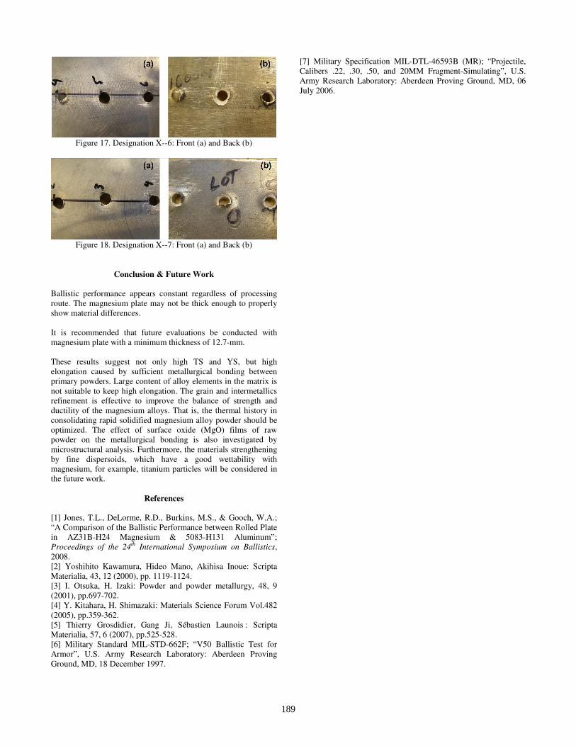
Figure 17. Designation X--6: Front (a) and Back (b)
Figure 18. Designation X--7: Front (a) and Back (b)
Conclusion & Future Work
Ballistic performance appears constant regardless of processing
route. The magnesium plate may not be thick enough to properly
show material differences.
It is recommended that future evaluations be conducted with
magnesium plate with a minimum thickness of 12.7-mm.
These results suggest not only high TS and YS, but high
elongation caused by sufficient metallurgical bonding between
primary powders. Large content of alloy elements in the matrix is
not suitable to keep high elongation. The grain and intermetallics
refinement is effective to improve the balance of strength and
ductility of the magnesium alloys. That is, the thermal history in
consolidating rapid solidified magnesium alloy powder should be
optimized. The effect of surface oxide (MgO) films of raw
powder on the metallurgical bonding is also investigated by
microstructural analysis. Furthermore, the materials strengthening
by fine dispersoids, which have a good wettability with
magnesium, for example, titanium particles will be considered in
the future work.
References
[1] Jones, T.L., DeLorme, R.D., Burkins, M.S., & Gooch, W.A.;
“A Comparison of the Ballistic Performance between Rolled Plate
in AZ31B-H24 Magnesium & 5083-H131 Aluminum”;
Proceedings of the 24th International Symposium on Ballistics,
2008.
[2] Yoshihito Kawamura, Hideo Mano, Akihisa Inoue: Scripta
Materialia, 43, 12 (2000), pp. 1119-1124.
[3] I. Otsuka, H. Izaki: Powder and powder metallurgy, 48, 9
(2001), pp.697-702.
[4] Y. Kitahara, H. Shimazaki: Materials Science Forum Vol.482
(2005), pp.359-362.
[5] Thierry Grosdidier, Gang Ji, Sébastien Launois : Scripta
Materialia, 57, 6 (2007), pp.525-528.
[6] Military Standard MIL-STD-662F; “V50 Ballistic Test for
Armor”, U.S. Army Research Laboratory: Aberdeen Proving
Ground, MD, 18 December 1997.
[7] Military Specification MIL-DTL-46593B (MR); “Projectile,
Calibers .22, .30, .50, and 20MM Fragment-Simulating”, U.S.
Army Research Laboratory: Aberdeen Proving Ground, MD, 06
July 2006.
189