Embed Size (px)
Citation preview

ISTITUTO NAZIONALE DI FISICA NUCLEARE
INFN-19-12/LNF8 July 2019
Initial electromagnetic and beam dynamics design of a Klystronamplifier for Ka-Band Accelerating Structures
Mostafa Behtouei, Luigi Faillace, Massimo Ferrario,Bruno Spataro and Alessandro Variola
INFN, Laboratori Nazionali di Frascati, P.O. Box 13, I-00044 Frascati, Italy
AbstractIn the framework of the Compact Light XLS project a compact third harmonic RF accel-erating structure at 35.982 GHz with respect to the main Linac frequency 11.994 GHz,working with an ultra-high gradient accelerating field in order to linearize the longitudinalspace phase is adopted. To this end an innovative high power Ka band klystron operatingat about 35.982 GHz has to be designed for feeding the linearizer structure. In addition,we also are planning to design a Ka band klystron operating on the third harmonic ofTM01 mode. The generation of a high density electron beam by using the Pierce typeelectron gun is also requested. The electron gun goal is to produce a converging highbeam current that matches to a focusing magnetic field in such way to obtain about 100MW beam power. This paper proposes a possible design of a electron gun to be usedin millimetric waves vacuum tubes. We here report the preliminary studies of the elec-tron gun and the related beam dynamic. Estimations have been obtained by using thenumerical code CST and analytical approaches.
Published byLaboratori Nazionali di Frascati

1 Introduction
From all the way back of birth of the electronics, electron guns are the heart of electrondevices. Vacuum tubes employ such electron source to produce the main electron currentto be manipulated, in order to generate the output signals. In beam physics and radiationtechnology applications, electron guns are employed to produce a fundamental currentof low energy electron. Such current can be injected in a linear accelerator to increaseelectron energy or can be directly used to generate ionizing radiation, by impacting on anad-hoc target. The next generation of linear accelerators require unprecedented acceler-ating gradients for high energy physics and particle physics experiments. Technologicaladvancements are strongly required to fulfill demands of compact linear accelerators forparticle physics colliders, new accelerators devices from the compact or portable devicesfor radiotherapy to mobile cargo inspections and security, biology, energy and environ-mental applications and so on. The advantages of using high frequency accelerating struc-tures are well known: smaller size, higher shunt impedance, higher breakdown thresholdlevel and short filing time. Ultimately large electric gradients are also required for a va-riety of new applications, notably including the extreme high brightness electron sourcesfor the FELs, RF photo-injector etc. Technological activities to design, manufacture andtest new accelerating devices using different materials and methods are under way allover the world. In the framework of the Compact light XLS project, the main linac fre-quency is F=11.994GHz. In order to compensate the non-linearity distortions due to theRF curvature of the accelerating cavities, the use of a compact third harmonic accelerat-ing structure working at F = 35.982 GHz is required [1–3]. Our concern is design a highpower Ka band klystron in order to feed a constant impedance accelerating structure oper-ating on the 2π/3 mode with an average (100-125) MV/m accelerating electric field rangeby using the conservative main RF parameters. For this reasons we are planning to final-ize the structure design as well as engineering of the RF power source that will be ableto produce up to a 40-50 MW input power by using a SLED system [4,5] since the theo-retical efficiency of the third harmonic Klystron operating on the TM01 mode is aroundthe 18% (about a factor 3 less than the standard klystron efficiency). As a result, in orderto obtain the RF power source requested, a 100 MW electron gun beam power is neededby knowing that the output cavity is operated in the third harmonic of the drive frequencyin the TM01 mode. Space charge force is one of the limitation which doesn’t allow tohave identical velocity for each accelerated electrons after passing through the cavitiesby affecting the bunching process which leads to the low efficiency. The key element tocontrol and measure such a force is known as perveance, K = I V −3/2. The higher theperveance, the stronger the space charge and consequently the weaker the bunching. Onthe other hand, since the perveance means how much current comes out of cathode for acertain voltage difference applied between the cathode and anode, to have a higher beamcurrent we should rise the perveance, but higher perveance leads to low efficiency. As aresults we have to find an optimal perveance to maintain a good efficiency. In this paper,
2

a Ka-Band Klystron amplifer is being investigated in order to feed Ka-Band acceleratingstructures. The initial design is presented including the high-power DC gun and the beamfocusing channel.
2 Electron Gun Injector Beam Dynamics Estimations
We have started the design of Pierce-type electron gun as a part of a klystron operating atKa-Band (35 GHz) in order to feed the accelerating structure. In this case, the cathode-anode voltage is about 500 kV, producing a beam current of about 200 A and beam powerup to 100 MW. In Fig. 1, the preliminary simulation of the electron gun with CST isshown. Beam trajectory (left) and electric field equipotential lines (right) have been
Figure 1: Preliminary electron gun design from CST. Beam trajectory (left) and Equipo-tential lines (right) are shown.
shown. The cathode-anode geometry was optimized to adjust the electric field equipo-tential lines in order to obtain maximum beam current extraction and capture (above 200A). Design parameters of diode gun for Ka-band klystron have shown in Table 1.
Table 1: Design parameters of diode gun for Ka-band klystronBeam power [MW] 118Beam voltage [kV] 500Beam current [A] 238
µ− perveance [I/V 3/2] 0.67Cathode diameter [mm] 76
Max EF on focusing electrode [kV/cm] 240Electrostatic compression ratio 210
3
We obtained the electrostatic beam compression ratio of 210: 1. To rise the com-pression ratio we have to apply focusing magnetic field and it will be reported in thenext section. The µ perveance of the device is 0.67 AV −3/2. It is common to use mi-cro perveance because its order is typically of 10−6 AV −3/2. Maximum electric field onfocusing electrode is about 240 kV/cm which is a reasonable value. In order to avoidpossible damage for a safety operation margin in terms of pulse length, windows, powersupply hardware stability, etc., we have decided to work with a 480 kV cathode-anodevoltage with maximum electric field of ∼ 200 kV/cm on focusing electrode as it will bereported in the next section.
3 Magnetostatic Simulation
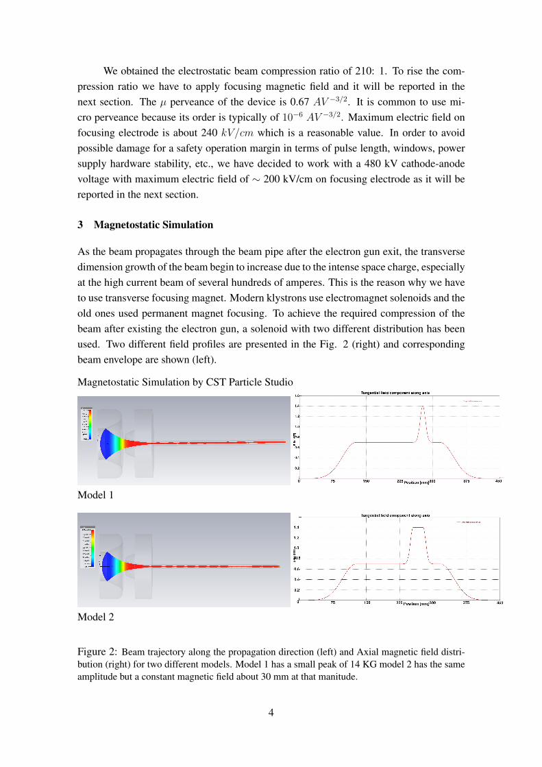
As the beam propagates through the beam pipe after the electron gun exit, the transversedimension growth of the beam begin to increase due to the intense space charge, especiallyat the high current beam of several hundreds of amperes. This is the reason why we haveto use transverse focusing magnet. Modern klystrons use electromagnet solenoids and theold ones used permanent magnet focusing. To achieve the required compression of thebeam after existing the electron gun, a solenoid with two different distribution has beenused. Two different field profiles are presented in the Fig. 2 (right) and correspondingbeam envelope are shown (left).
Magnetostatic Simulation by CST Particle Studio
Model 1
Model 2
Figure 2: Beam trajectory along the propagation direction (left) and Axial magnetic field distri-bution (right) for two different models. Model 1 has a small peak of 14 KG model 2 has the sameamplitude but a constant magnetic field about 30 mm at that manitude.
4
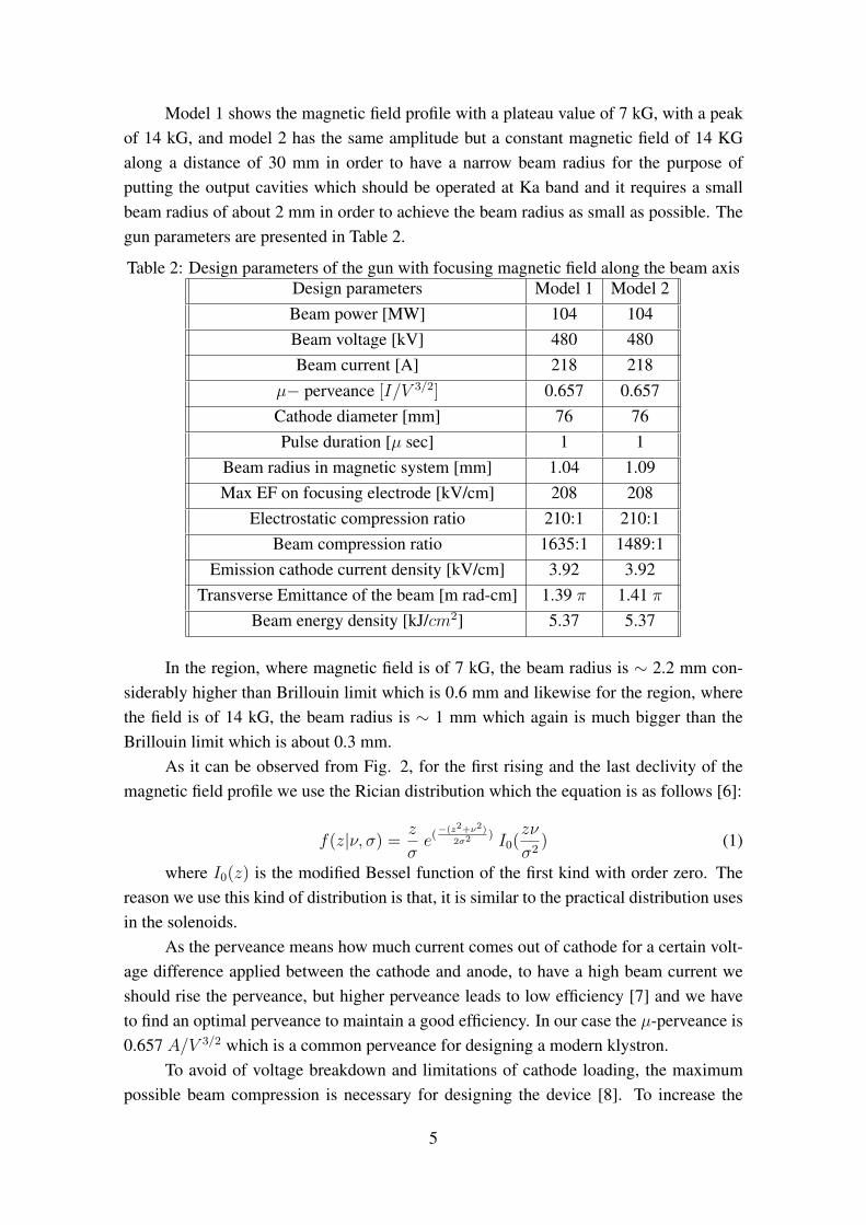
Model 1 shows the magnetic field profile with a plateau value of 7 kG, with a peakof 14 kG, and model 2 has the same amplitude but a constant magnetic field of 14 KGalong a distance of 30 mm in order to have a narrow beam radius for the purpose ofputting the output cavities which should be operated at Ka band and it requires a smallbeam radius of about 2 mm in order to achieve the beam radius as small as possible. Thegun parameters are presented in Table 2.
Table 2: Design parameters of the gun with focusing magnetic field along the beam axisDesign parameters Model 1 Model 2Beam power [MW] 104 104Beam voltage [kV] 480 480Beam current [A] 218 218
µ− perveance [I/V 3/2] 0.657 0.657Cathode diameter [mm] 76 76Pulse duration [µ sec] 1 1
Beam radius in magnetic system [mm] 1.04 1.09Max EF on focusing electrode [kV/cm] 208 208
Electrostatic compression ratio 210:1 210:1Beam compression ratio 1635:1 1489:1
Emission cathode current density [kV/cm] 3.92 3.92Transverse Emittance of the beam [m rad-cm] 1.39 π 1.41 π
Beam energy density [kJ/cm2] 5.37 5.37
In the region, where magnetic field is of 7 kG, the beam radius is ∼ 2.2 mm con-siderably higher than Brillouin limit which is 0.6 mm and likewise for the region, wherethe field is of 14 kG, the beam radius is ∼ 1 mm which again is much bigger than theBrillouin limit which is about 0.3 mm.
As it can be observed from Fig. 2, for the first rising and the last declivity of themagnetic field profile we use the Rician distribution which the equation is as follows [6]:
f(z|ν, σ) = z
σe(
−(z2+ν2)
2σ2) I0(
zν
σ2) (1)
where I0(z) is the modified Bessel function of the first kind with order zero. Thereason we use this kind of distribution is that, it is similar to the practical distribution usesin the solenoids.
As the perveance means how much current comes out of cathode for a certain volt-age difference applied between the cathode and anode, to have a high beam current weshould rise the perveance, but higher perveance leads to low efficiency [7] and we haveto find an optimal perveance to maintain a good efficiency. In our case the µ-perveance is0.657 A/V 3/2 which is a common perveance for designing a modern klystron.
To avoid of voltage breakdown and limitations of cathode loading, the maximumpossible beam compression is necessary for designing the device [8]. To increase the
5

beam compression one should take into account the transverse emittance because increas-ing the beam compression for having the minimum beam radius, transverse emittancerises as we can observe from Fig 3.
(a)
(b)
Figure 3: a) beam envelope and b) transverse emittance of the beam along the beam axisat the presence of the focusing magnetic field
We have obtained the magnetostatic beam compression ratio of 1635:1 for themodel 1 where the beam radius is ∼ 1 mm. It should be noted that it would be pos-sible to rise the beam compression ratio more than 2000:1 just by decreasing the beamradius to 0.9 mm. The maximum possible compression ratio is 4914 where the beam ra-dius arrives to the Brillouin limit of 0.6 mm. The problem of higher compression ratio,as we have mentioned before, which results in transverse emittance growth of the beamwhere the walls intercept the beam. The transverse emittance of the beam for the model1 and 2 are 1.39 π (m rad-cm) and 1.41 π (m rad-cm), respectively.
4 The main device limitations
In designing a high power klystron we have some limitations: a) beam current limitationb) beam radius limitation and c) cathode material limitation. As the perveance means howmuch current comes out of cathode for a certain voltage difference applied between thecathode and anode, to have a high beam current we should rise the perveance, but higherperveance leads to low efficiency and we have to find an optimal perveance to maintain agood efficiency. The beam radius r cannot be less than the Brillouin limit,
rb =0.369
B
√I
βγmm (2)
6

where,I: Current beam (I=235A)β: v/c for relativistic particle (β = 0.860)γ: Relativistic mass (energy) factor (γ = 1.957)B: Magnetic field in kG ( B=14 kG)and finally we investigated the later limitation which is the common materials used
as a source of current emission. Tungsten filament and Lanthanum hexaboride (LaB6) aretwo common materials used as source of current emission. LaB6 has bigger lifetime thanTungsten. The other advantage of LaB6 is that, emitted current is much bigger due to thelow work function. We reported the properties of these material in Table 3.
Table 3: Properties of cathode materialsProperties Tungsten filament Lanthanum hexaboride (LaB6)
Operating temperature [◦K] 2700-3000 1700-2100Emitted current (Jc) [A/cm2] 1.75 40-100
Required vacuum [Pa] 10−3 10−4
Average life time [hr] 60-100 longer than TungstenWork function [ev] 4.5 2.7
We decided to work with LaB6 as a cathode material in space charge regime limitedin order to get a greater current emission and less cathode damage.
5 Analytical method for estimating the dimensions of electron gun device
An expression for the potential distribution between the cathode and anode may be ob-tained from considering Poisson’s equation. Poisson’s equation in spherical coordinatesis,
1
r2∂
∂r(r2
∂V
∂r) +
1
r2sinθ
∂
∂θ(sinθ
∂V
∂θ) +
1
r2sin2θ
∂2V
∂φ2= − ρ
ε0(3)
We have no variation of the potential in θ and φ coordinates because of the symme-try about the axes and the equation above becomes:
1
r2∂
∂r(r2
∂V
∂r) = − ρ
ε0=
I
4πr2νε0(4)
The above equation can be solved in terms of a series by H. M. Mott-Smith method[9]. The final solution takes the form [10],
I =16πε09
√−2em
V 3/2
(−α)2=
16πε09
√−2em
V 3/2(rcra)2 (5)
where α is a function of the ratio of the radii ra and rc of the spheres, rc being theradius of the emitter and ra is the anode radius (see Fig. 4), γ = log( ra
rc)
7
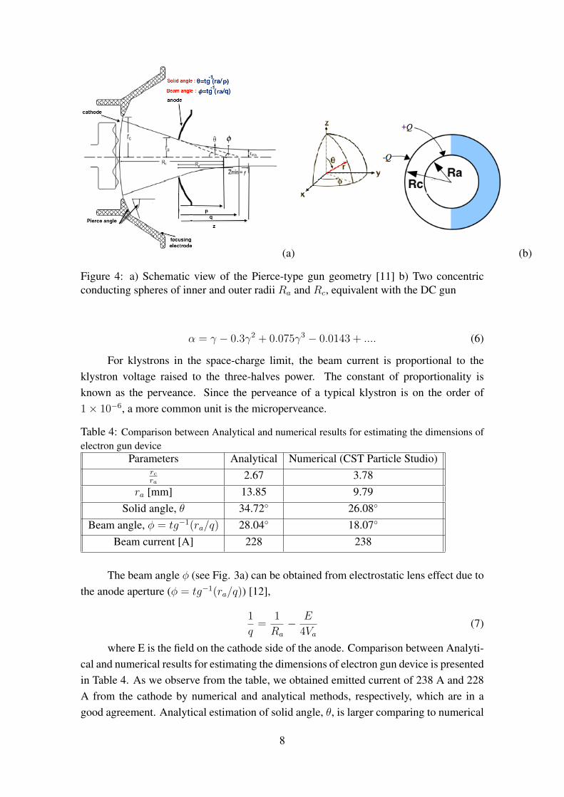
(a) (b)
Figure 4: a) Schematic view of the Pierce-type gun geometry [11] b) Two concentricconducting spheres of inner and outer radii Ra and Rc, equivalent with the DC gun
α = γ − 0.3γ2 + 0.075γ3 − 0.0143 + .... (6)
For klystrons in the space-charge limit, the beam current is proportional to theklystron voltage raised to the three-halves power. The constant of proportionality isknown as the perveance. Since the perveance of a typical klystron is on the order of1× 10−6, a more common unit is the microperveance.
Table 4: Comparison between Analytical and numerical results for estimating the dimensions ofelectron gun device
Parameters Analytical Numerical (CST Particle Studio)rcra
2.67 3.78ra [mm] 13.85 9.79
Solid angle, θ 34.72◦ 26.08◦
Beam angle, φ = tg−1(ra/q) 28.04◦ 18.07◦
Beam current [A] 228 238
The beam angle φ (see Fig. 3a) can be obtained from electrostatic lens effect due tothe anode aperture (φ = tg−1(ra/q)) [12],
1
q=
1
Ra
− E
4Va(7)
where E is the field on the cathode side of the anode. Comparison between Analyti-cal and numerical results for estimating the dimensions of electron gun device is presentedin Table 4. As we observe from the table, we obtained emitted current of 238 A and 228A from the cathode by numerical and analytical methods, respectively, which are in agood agreement. Analytical estimation of solid angle, θ, is larger comparing to numerical
8
results and this results a bigger anode radius as we observe from the Table 4. Numericalcalculations for the other parameters such as beam angle and the ratio between cathoderadius and anode radius are in agreement with the analytical ones.
Conclusions
In this paper, we have performed the initial electromagnetic and beam dynamicsdesign of an RF Klystron amplifier in order to feed Ka-Band accelerating structures,by using the Microwave CST code. The klystron works on the third harmonic of thebunched electron beam (∼35 GHz). The electron flow is generated from a high-voltageDC gun (up to 500 kV) and the cathode-anode geometry was optimized to adjust theelectric field equipotential lines in order to obtain maximum beam current extraction andcapture (above 200 A). The electron beam is then transported through the klystron chan-nel. The beam confinement is obtained by means of a high magnetic field produced bysuperconducting coils, in the current design , which was analytically imported into thecode. The channel optimization allows to deliver a 100 MW electron beam with a spotsize below 2mm diameter. We are currently working on the 2D beam dynamics designof the input, bunching and output RF cavities of this klystron and further details will begiven in a following paper. A tapered tunnel is expected to be installed in order to al-locate Ka-band output cavities. We are also considering the possibility of using normalconducting coils instead of superconducting ones.
References
[1] M. Behtouei, L. Faillace, M. Ferrario, B. Spataro and A. Variola, “A Ka-band TWaccelerating structure as RF linearizer for the Compact Light XLS project”, INFN-19-11/LNF, Jun 2019
[2] Faillace L, Behtouei M, Dolgashev V, Spataro B, Torrisi G, Variola A. “Compact Ul-tra High-Gradient Ka-Band Accelerating Structure for Research, Medical and Indus-trial Applications”. In10th Int. Partile Accelerator Conf.(IPAC’19), Melbourne, Aus-tralia, 19-24 May 2019 2019 Jun 1 (pp. 2842-2845). JACOW Publishing, Geneva,Switzerland.
[3] Behtouei M, Faillace L, Migliorati M, Palumbo L, Spataro B. “New AnalyticalDerivation of Group Velocity in TW Accelerating Structures”. In10th Int. PartileAccelerator Conf.(IPAC’19), Melbourne, Australia, 19-24 May 2019 2019 Jun 1(pp. 155-158). JACOW Publishing, Geneva, Switzerland.
9
[4] Ivanov, O. A., et al. “Active quasioptical Ka-band rf pulse compressor switched by adiffraction grating.”. Physical Review Special Topics-Accelerators and Beams 12.9(2009): 093501.
[5] Ivanov, O. A., et al. “Active microwave pulse compressor using an electron-beamtriggered switch.”. Physical review letters 110.11 (2013): 115002.
[6] Rice, Stephen O. “Mathematical analysis of random noise.”Bell System TechnicalJournal 23.3 (1944): 282-332.
[7] Y. H. Chin, Proceedings of LINAC08, TU204, Victoria, BC, Canada.
[8] Yakovlev, V. P., and O. A. Nezhevenko. “Limitations on area compression of beamsfrom pierce guns”. AIP Conference Proceedings. Vol. 474. No. 1. AIP, 1999.
[9] I. Langmuir, Phys. Rev. 2, 450, 1913; Phys. Zeits. 15, 348, 1914.
[10] I. Langmuir and B. Blodgett, Phys. Rev. “Currents limited by space charge betweenconcentric spheres”. 15, 348, 1924
[11] Pierce, J. R. “Rectilinear electron flow in beams.”, Journal of Applied Physics 11.8(1940): 548-554.
[12] Haimson, J. “High Current Traveling Wave Electron Linear Accelerators”, IEEETransactions on Nuclear Science 12.3 (1965): 996-1011.
10