Embed Size (px)
Citation preview
1 The six organizations are Nuclear Information and Resource Service; JerseyShore Nuclear Watch, Inc.; Grandmothers, Mothers and More for Energy Safety; New JerseyPublic Interest Research Group; New Jersey Sierra Club; and New Jersey EnvironmentalFederation.
LBP-07-17
UNITED STATES OF AMERICANUCLEAR REGULATORY COMMISSION
ATOMIC SAFETY AND LICENSING BOARD
Before Administrative Judges:
E. Roy Hawkens, ChairmanDr. Paul B. AbramsonDr. Anthony J. Baratta
In the Matter of
AMERGEN ENERGY COMPANY, LLC
(License Renewal for Oyster Creek NuclearGenerating Station)
Docket No. 50-0219-LR
ASLBP No. 06-844-01-LR
December 18, 2007
INITIAL DECISION(Rejecting Citizens’ Challenge To AmerGen’s Application To Renew
Its Operating License For The Oyster Creek Nuclear Generating Station)
I. INTRODUCTION
AmerGen Energy Company, LLC (“AmerGen”) seeks a twenty-year renewal of its
operating license for the Oyster Creek Nuclear Generating Station (“Oyster Creek”), which
expires on April 9, 2009. The intervenors in this case – six organizations hereinafter referred to
collectively as Citizens1 – argue that AmerGen’s license renewal request must be denied
because its aging management program for corrosion of the drywell shell in the sand bed region
is inadequate. More precisely, they argue that AmerGen’s plan to take ultrasonic testing (“UT”)
measurements in the sand bed region every four years is not sufficiently frequent to ensure an
adequate safety margin is maintained between measurements due to the uncertain condition of
the drywell shell, the uncertain corrosive environment, and the uncertain corrosion rate. Having
- 2 -
fully considered all the record evidence, including the testimony presented at the two-day
hearing conducted on September 24 and 25, 2007, we find that AmerGen has demonstrated
that the frequency of its planned UT measurements, in combination with the other elements of
its aging management program, provides reasonable assurance that the sand bed region of the
drywell shell will maintain the necessary safety margin during the period of extended operation.
II. BACKGROUND
A. The Drywell Shell
The drywell shell is a steel structure enclosing the Oyster Creek reactor plant. It is
designed to withstand the potential pressures and temperatures associated with a break of any
of the enclosed reactor cooling system pipes, thereby containing the release of fission products
and ensuring that offsite radiation consequences do not exceed acceptable limits. See
AmerGen’s Exh. B, AmerGen’s Pre-Filed Direct Testimony Parts 1-7 (July 20, 2007), Pt. 1, A.8.
The drywell shell is about 100 feet tall and shaped like an inverted light bulb. It
measures about 70 feet in diameter at the spherical base. At a height of about 71 feet 6 inches,
it transitions from a spherical shape to a cylindrical shape that is about 33 feet in diameter. See
AmerGen Exh. B, Pt. 1, A.7; AmerGen Exh. 4, Schematic Drawing of the Cross-Section of the
Drywell Shell.
The drywell shell – which is surrounded by a concrete shield wall – is set in and arises
from a concrete pedestal atop the reactor building concrete foundation at an elevation of about
2 feet 3 inches relative to mean sea level. The shell is embedded in concrete on both sides
from its bottom to a height of about 8 feet 11 inches, where the exterior drywell shell concrete
floor is located. The interior of the shell remains embedded in concrete up to a height of about
11 feet (beneath the torus vent headers) and 12 feet 3 inches (areas between the torus vent
- 3 -
2 The torus is a torroidal-shaped steel pressure vessel that encircles the base ofthe drywell shell and is partially filled with water to provide pressure suppression in the event ofa loss-of-coolant accident. The shell is connected to the torus through ten cylindrical ventheaders that protrude from the lower, spherical section of the shell. See AmerGen Exh. B, Pt.1, A.10, A.11.
headers). See AmerGen Exh. B, Pt. 1, A.7, A.9; AmerGen Exh. 4; AmerGen Exh. 5, Schematic
Drawing of the Drywell Shell Exterior.2
The region of the shell known as the “sand bed” region begins at a shell height of 8 feet
11 inches (the level of the exterior concrete floor) and extends to 12 feet 3 inches. This region
originally was constructed with a bed of sand on its exterior to structurally support the shell as it
transitions from being embedded in concrete on both sides below 8 feet 11 inches to being
embedded only on the interior. The sand bed region is divided into ten circumferential bays,
each of which is designated with an odd number from one through nineteen, and each of which
has an associated torus vent header. Five sand bed drains – equally spaced throughout the
bays and located in the concrete floor of the external sand bed region – are designed to drain
water that might reach the sand bed floor and flow into the torus room below. Water from these
drains is diverted through plastic tubing where it can be collected in five-gallon plastic bottles.
See AmerGen Exh. B, Pt. 1, A.9, A.10; AmerGen Exh. 5; AmerGen Exh. 6, Schematic Drawing
Showing Top View of the Ten Bays in the Sand Bed Region; AmerGen Exh. 7, Schematic
Drawing Showing Detail of the Lower Drywell/Sand Bed Region.
On the exterior of the drywell shell, above the sand bed region and rising to the top of
the shell, there is a gap of a few inches that separates the shell from the concrete shield wall.
This small gap was filled during construction with a cement-composite product, which was
subsequently compressed by heating, resulting in an air gap to allow expansion of the shell
under design basis loads. See AmerGen Exh. B, Pt. 1, A.12; AmerGen Exhs. 4, 7.
- 4 -
3 The refueling cavity is also known as the reactor cavity, but we will use theformer name. See AmerGen Exh. B, Pt. 1, A.13.
4 Oyster Creek operates on a two-year refueling cycle. During normal refuelingoutages, the refueling cavity is filled with water for less than 26 days once every two years. Forinstance, during the most recent refueling outage in 2006, the refueling cavity was filled withwater for about 17 days. See AmerGen Exh. B, Pt. 1, A.13, A.16, A.17; Tr. at 689 (O’Rourke);Tr. at 692 (Ray).
5 A “rad” is a measure of absorbed dose of ionizing radiation.
The refueling cavity3 is located above the drywell shell at the top of the reactor building
concrete shield wall. This cavity – which ordinarily is empty – is filled with water only during
refueling outages,4 or in the rare event of an outage when the reactor vessel must be opened for
a purpose other than refueling. The refueling cavity drainage system has a concrete trough
located below the cavity to collect water that might leak from the cavity when it is filled with
water. The trough has a 2-inch drain line designed to direct leakage to the reactor building
drain tank and prevent water from entering the gap between the drywell shell exterior and the
concrete shield wall. See AmerGen Exh. B, Pt. 1, A.14; AmerGen Exh. 8, Schematic Drawing
Showing Detail of the Reactor Cavity Seal and Trough Drain.
The average normal operating temperature inside the drywell shell is 139 degrees
Fahrenheit. During reactor operations, maximum expected temperature outside the shell in the
sand bed region is about 109.5 degrees Fahrenheit. During outages, the sand bed region
temperatures range up to about 90 degrees Fahrenheit. See AmerGen Exh. B, Pt. 1, A.18; Tr.
at 790, 794 (Hosterman).
Radiation levels inside the drywell shell in the sand bed region are about 4.7 to 5.6 rads
per hour,5 and consist primarily of gamma radiation. Radiation levels on the outside of the shell
in the sand bed region are slightly lower. See AmerGen Exh. B, Pt. 1, A.19.
- 5 -
6 In 2000, the NRC approved the transfer of the Oyster Creek license from thethen-licensee, GPU Nuclear, Inc. and Jersey Central Power & Light Company, to AmerGen (65Fed. Reg. 37,417 (June 14, 2000)).
B. The Discovery In The 1980s Of Corrosion Of The Drywell Shell, And TheSubsequent Corrective Actions
Oyster Creek began operation in 1969. In the late 1980s, the then-licensee6 discovered
water had leaked onto the outer wall of the drywell shell, causing significant corrosion predomi-
nantly in the top of the sand bed region. After extensive investigations, the then-licensee
determined that the source of water was leakage through small cracks in the refueling cavity
liner. See AmerGen Exh. B, Pt. 1, A.20, A.21; NRC Staff Exh. B, A.5; Tr. at 324 (Hausler).
The leakage from the liner – which occurred when the refueling cavity was filled with
water – should have been collected by the concrete trough and directed by the drain line to the
reactor building drain tank. The amount of leaking water, however, was greater than the capa-
city of the trough and drain pipe. Moreover, due to defects in the trough lip and a blocked drain,
the trough did not contain the leaking water, which overflowed into the expansion gap (i.e., the
gap between the exterior of the drywell shell and the concrete shield wall) and down into the
sand bed region. See AmerGen Exh. B, Pt. 1, A.20; AmerGen Exhs. 7, 8; AmerGen Exh. 9,
Schematic Drawing Showing Detail of the Reactor Cavity.
The water soaked into the sand, which kept moisture in direct and prolonged contact
with the drywell shell, causing significant corrosion of the exterior shell before corrective actions
were taken (AmerGen Exh. B, Pt. 1, A.20, A.21; Tr. at 323-24 (Hausler)). Also contributing to
the prolonged corrosive condition were drywell shell drainage problems. Specifically, the sand
bed drains were later discovered to be clogged, preventing proper drainage of water once it
reached the bottom of the sand bed. Additionally, portions of the sand bed floor were not
properly finished, hindering drainage toward the sand bed drains. See AmerGen Exh. B, Pt. 1,
A.20, A.21.
- 6 -
7 The NRC Staff testified that about 50 percent of the sand bed region was notsignificantly degraded (i.e., the wall thickness in four bays is over an inch thick and the baysshow no sign of degradation), and 80 percent of the sand bed region is 800 to 900 mils thick(i.e., 0.80 to 0.90 inch thick). See Tr. at 633-35 (Tamburro).
8 Tape and strippable coating were not applied during the 1994 and 1996 refuelingoutages. See AmerGen Exh. B, Pt. 1, A.23.
The resulting corrosion in the sand bed region was unevenly distributed among or within
the ten bays. However, in those bays where corrosion occurred, it was most significant near the
top of the sand bed region where the sand retained moisture and the air/water interface existed.
See AmerGen Exh. B, Pt. 1, A.22; Tr. at 324 (Hausler); Tr. at 344-45 (Gallagher). Additionally,
corrosion generally was greatest in the vicinity of the torus vent headers, not between them. By
way of reference, the design thickness of the drywell shell in the sand bed region is 1.154
inches. Although some bays exhibited almost no observable corrosion, some experienced
considerable corrosion, with Bay 19 experiencing a maximum general average metal loss of
about 0.35 inch over an area that is six inches by six inches. See AmerGen Exh. B, Pt. 1, A.22;
Tr. at 472-73 (Tamburro).7
The then-licensee of Oyster Creek took multiple mitigating actions in the 1980s and early
1990s to address the corrosion problem. These actions included: (1) boring ten access holes
through the concrete shield wall to access the ten bays to remove the sand from the sand bed
region; (2) cleaning the exterior of the drywell shell; (3) applying a multi-layer epoxy coating on
the drywell shell exterior in the sand bed region; (4) repairing the concrete sand bed floor to pro-
mote drainage in those bays where the floor was not properly finished; (5) clearing the sand bed
drains; (6) applying epoxy caulk at the drywell shell/sand bed floor junction; (7) repairing the
leakage collection trough in the refueling cavity and clearing the trough drain; (8) applying
stainless steel tape and a strippable coating to the refueling cavity during refueling outages to
seal cracks in the cavity liner and reduce leakage;8 and (9) taking periodic UT measurements
- 7 -
9 Two trenches were excavated in 1986 from the interior concrete floor in Bays 5and 17 to permit UT measurements from inside the drywell shell. Bay 5 was selected becauseit was believed to have little external corrosion, and Bay 17 was selected because it wasbelieved to have severe external corrosion. The Bay 17 trench has its base at a height of about9 feet 3 inches, which is the lowest elevation from which AmerGen has UT grid data on severelycorroded surfaces. The trench in Bay 5 is deeper than the trench in Bay 17, but Bay 5 has littlecorrosion. See AmerGen Exh. 40, AmerGen’s Oyster Creek Generating Station LicenseRenewal ACRS Presentation, at 53 (Jan. 18, 2007); Tr. at 343-44 (Gallagher); Tr. at 681-82(Polaski).
10 The “current licensing basis” is the “set of NRC requirements applicable to aspecific plant and a licensee’s written commitments . . . and the plant-specific design basis(including all modifications and additions to such commitments over the life of the license) thatare docketed and in effect” (10 C.F.R. § 54.3). The full definition is provided infra note 17.
11 Any significant deviations of UT results will require corrective action prior to any(continued...)
from inside and outside the shell to ensure it maintained an adequate safety margin and was
not experiencing further corrosion.9 See AmerGen Exh. B, Pt. 1, A.23, A.24.
AmerGen concluded that, as a result of the corrective actions, the corrosion of the
exterior drywell shell had been arrested. See AmerGen Exh. B, Pt. 1, A.24.
C. AmerGen’s Commitments To Manage Corrosion Of The Drywell Shell During The Period Of Extended Operation
In support of its License Renewal Application, AmerGen made numerous commitments
to the NRC Staff to demonstrate that its aging management program for the drywell shell
provided reasonable assurance that the effects of aging (e.g., corrosion) will be adequately
managed during the twenty-year renewal period such that the shell will perform its intended
functions (i.e., structural integrity and pressure containment) consistent with the current
licensing basis.10 AmerGen’s commitments include performing a full scope sand bed region
inspection during the 2008 refueling outage and thereafter at every other refueling outage
throughout the renewal period (i.e., every four years). A full scope sand bed region inspection
consists of: (1) taking UT measurements using the same internal grids AmerGen previously has
used, as well as over 100 external locations that were measured during the 2006 outage;11 (2)
- 8 -
11(...continued)restart. Such corrective action includes promptly notifying the NRC Staff, performing confirma-tory UT measurements, performing an engineering evaluation to assess the extent of thecondition and to determine whether additional inspections are required to assure drywell shellintegrity, and performing an operability determination and justification for operation until the nextinspection (AmerGen Exh. B, Pt. 1, A.27).
12 At the evidentiary hearing, AmerGen also agreed – as a condition of the renewedlicense – to inspect the sand bed drains for blockage at intervals consistent with its existinginternal procedures (Tr. at 793, 843-44) (Tamburro, Gallagher). We understand that the NRCStaff will coordinate with AmerGen to ensure the frequency of such inspections are adequate(Tr. at 800) (Ashar).
making visual inspections of the external shell epoxy coating in all ten bays; and (3) inspecting
the seal at the junction between the sand bed region concrete and the embedded drywell shell.
See AmerGen Exh. B, Pt. 1, A.27.
To address leakage from components inside the drywell, AmerGen committed to moni-
toring the two trenches inside the drywell shell (in Bays 5 and 17) for the presence of water until
no water is identified for two consecutive outages (NRC Staff Exh. B, A.12(a); NRC Staff Exh. 1,
Excerpts from Safety Evaluation Report, at A-31 to A-32 (Apr. 2007)). To eliminate water on the
drywell shell exterior, AmerGen committed to monitoring the sand bed region drain for water on
a daily basis during outages when the refueling cavity is filled with water (AmerGen Exh. B, Pt.4,
A.4), as well as on a quarterly basis during the operating cycle when the cavity is not filled with
water (ibid.), and to take corrective action if water is found (AmerGen Exh. B, Pt. 1, A.27).12
AmerGen also committed to using a strippable coating on the refueling cavity wall during
periods when the cavity is flooded, which has been shown to be effective in mitigating water
intrusion into the gap between the exterior drywell shell and the concrete shield wall (ibid.).
Finally, AmerGen committed to inspecting the multi-layer epoxy coating on the exterior
wall of the shell in the sand bed region in accordance with American Society of Mechanical
Engineers (“ASME”) Code Section XI, Subsection IWE, and to performing repairs, as neces-
sary, to manage corrosion. This inspection commitment provides that: (1) the areas will be
- 9 -
13 When Citizens submitted their petition, AmerGen’s LRA contained no provisionfor future UT measurements in the sand bed region of the drywell shell based on its conclusionthat corrosion in that region had been arrested and that the planned visual inspections of themulti-layered epoxy coating in that region would be sufficient to manage any unexpected corro-sion problems during the renewal period. During the pendency of the license renewal reviewprocess, AmerGen docketed several commitments that progressively enhanced its agingmanagement program for the sand bed region of the drywell shell, resulting ultimately in thecurrent commitment at issue in this proceeding; namely, the commitment to perform UTmeasurements every four years. See AmerGen Exh. 10, Letter from Michael P. Gallagher,AmerGen, to U.S. NRC (Feb. 15, 2007), Enclosing Additional Commitments Related to theAging Management Program for the Oyster Creek Drywell Shell Associated with AmerGen’sLicense Renewal Application, Commitment 27(1).
visually examined for evidence of flaking, blistering, peeling, discoloration, and other signs of
distress; (2) areas that are suspect will be subjected to engineering evaluation or correction by
repair or replacement in accordance with IWE-3122; and (3) supplemental examinations in IWE-
3200 will be performed when specified as a result of the engineering evaluation. See AmerGen
Exh. B, Pt. 1, A.27; NRC Staff Exh. B, A.15.
D. The Litigative History Of AmerGen’s License Renewal Application
By letter dated July 22, 2005, AmerGen submitted an application to renew its operating
license for Oyster Creek for a twenty-year period pursuant to 10 C.F.R. Part 54. The current
license will expire on April 9, 2009.
Citizens filed a petition for a hearing in response to the NRC’s publication of a notice of
opportunity for hearing in the Federal Register (70 Fed. Reg. 54,585 (Sept. 15, 2005)). As
relevant here, in LBP-06-07, 63 NRC 188, 194 (2006), this Board granted Citizens’ hearing
request, concluding that Citizens had standing and had submitted an admissible contention.
The admitted contention alleged that AmerGen’s License Renewal Application (“LRA”) was
deficient due to the failure to include periodic UT measurements in the sand bed region of the
drywell shell in the aging management program.13
In LBP-06-16, 63 NRC 737, 741-45 (2006), this Board ruled that Citizens’ contention
was rendered moot by AmerGen’s April 4, 2006 docketed commitment to perform periodic UT
- 10 -
14 During the course of this proceeding, this Board concluded that the followingcontentions proffered by Citizens were not admissible because they were nontimely, or failed tosatisfy admissibility standards, or both: (1) Citizens’ challenge to AmerGen’s monitoring pro-gram for areas of the drywell shell below and above the sand bed region (LBP-06-11, 63 NRC391, 396-400 (2006)); (2) Citizens’ challenge asserting that AmerGen be directed to conduct aroot cause analysis of the corrosion problem (id. at 400-01); (3) Citizens’ challenge to Amer-Gen’s modeling for deriving acceptance criteria (LBP-06-22, 64 NRC at 237-40; LicensingBoard Memorandum and Order at 6-12 (Apr. 10, 2007) (unpublished)); (4) Citizens’ challenge toAmerGen’s monitoring program in the sand bed region for moisture and coating integrity (LBP-06-22, 64 NRC at 244-48); (5) Citizens’ challenge to AmerGen’s program for responding to wetconditions and coating failure in the sand bed region (id. at 248-49); (6) Citizens’ challenge tothe scope of AmerGen’s UT monitoring program in the sand bed region (id. at 249-51; LicensingBoard Memorandum and Order at 7-19 (Feb. 9, 2007) (unpublished); (7) Citizens’ challenge toAmerGen’s quality assurance program for measurements in the sand bed region (LBP-06-22,64 NRC at 251-53); and (8) Citizens’ challenge to AmerGen’s methods for analyzing UT resultsin the sand bed region (id. at 254-55). See Licensing Board Memorandum and Order at 2 n.4(June 19, 2007) (unpublished).
measurements in the sand bed region of the drywell shell. However, we gave Citizens the
opportunity to file a new contention challenging the new periodic UT program embodied in
AmerGen’s April 2006 commitment.
In LBP-06-22, 64 NRC 229, 255-56 (2006), this Board admitted the following contention
that underlies the present proceeding:
[I]n light of the uncertain corrosive environment and the correlative uncertaincorrosion rate in the sand bed region of the drywell shell, AmerGen’s proposed[UT monitoring] plan . . . is insufficient to maintain an adequate safety margin.14
On September 20, 2007, this Board convened an evidentiary session to (1) determine
whether the witnesses proffered by the parties were qualified to present testimony in their
putative areas of expertise, and (2) receive into evidence their pre-filed written direct, rebuttal,
and sur-rebuttal testimony as exhibits (10 C.F.R. § 2.1207(b)(2)), as well as the parties’ other
exhibits. See Tr. at 199-200 (AmerGen Exhs. A-D and 1-61); Tr. at 231-32 (Citizens Exhs. A-D
and 1-62); Tr. at 247 (NRC Staff Exhs. A-D and 1-6). The Board found all the witnesses to be
qualified to present testimony in the areas they addressed. See Tr. at 250, 255, 258.
- 11 -
AmerGen presented, and this Board accepted into evidence as exhibits, the pre-filed
written testimony of the following fifteen witnesses: (1) Julien D. Abramovici, Enercon Services,
Inc.; (2) Jon R. Cavallo, Vice-President of Corrosion Control Consultants and Labs, Inc.; (3)
Scott R. Erickson, NDE Level III Inspector; (4) Michael P. Gallagher, Vice President for License
Renewal for Exelon; (5) Barry M. Gordon, Structural Integrity Associates, Inc.; (6) Dr. David G.
Harlow, Professor of Mechanical Engineering and Mechanics, Lehigh University; (7) Jon C.
Hawkins, NDE Level III Inspector; (8) Edwin W. Hosterman, Senior Staff Engineer, Corporate
Engineering Programs Group, Exelon; (9) Martin McAllister, NDE Level III Inspector; (10) Dr.
Hardayal S. Mehta, Chief Consulting Engineer, Mechanics GE-Hitachi Nuclear Energy Co.; (11)
Ahmed M. Ouaou, contractor engineer for Exelon; (12) John F. O’Rourke, Senior Project
Manager, License Renewal for Exelon; (13) Frederick W. Polaski, Manager of License Renewal
for Exelon; (14) Francis H. Ray, Engineering Programs Director at OCNGS; and (15) Peter
Tamburro, Senior Mechanical Engineer, OCNGS Engineering Department. See AmerGen Exh.
D, Professional Qualifications of AmerGen Witnesses; AmerGen Exh. B, Pts. 1-7; AmerGen
Exh. C, AmerGen’s Pre-Filed Rebuttal Testimony Parts 1-6 (Aug. 17, 2007); AmerGen Exh. C.1,
AmerGen’s Pre-Filed Surrebuttal Testimony Parts 1-6 (Sept. 14, 2007).
The NRC Staff presented, and this Board accepted into evidence as exhibits, the pre-
filed written testimony of the following five witnesses: (1) Hansraj G. Ashar, Senior Structural
Engineer, Division of Engineering, Office of Nuclear Reactor Regulation (“NRR”); (2) Dr. James
A. Davis, Senior Materials Engineer, NRR Division of License Renewal; (3) Dr. Mark Hartzman,
Senior Mechanical Engineer, NRR Division of Engineering; (4) Timothy L. O’Hara, Reactor
Inspector, Division of Reactor Safety, NRC Region I Office; and (5) Arthur D. Salomon,
Research (Mathematical) Statistician, Office of Nuclear Regulatory Research. See NRC Staff
Exh. D, Professional Qualifications of NRC Staff Witnesses; NRC Staff Exh. B; NRC Staff Exh.
- 12 -
15 NRC Staff Exhibit D also included the professional qualifications of two witnesseswho neither submitted pre-filed testimony nor testified during the hearing. Citizens argued that,because these individuals had not been identified as witnesses until very late in the proceeding – i.e., on September 18, 2007 (Tr. at 248) – and had not submitted pre-filed testimony, theyought not be permitted to testify at the evidentiary hearing unless Citizens were provided with areasonable time thereafter to rebut such testimony (Tr. at 241-43, 258-60). Because these twowitnesses did not testify at the hearing, Citizens’ argument was rendered moot.
C, NRC Staff Rebuttal Testimony and Answer to Board Questions (Aug.17, 2007); NRC Staff
Exh. C.1, NRC Staff Sur-Rebuttal Testimony (Sept. 14, 2007).15
Finally, Citizens presented, and this Board accepted into evidence as exhibits, the
testimony of Dr. Rudolf H. Hausler, President, Corro-Consulta. See Citizens Exh. D,
Professional Qualifications of Dr. Rudolf H. Hausler; Citizens Exh. B, Initial Pre-Filed Written
Testimony of Dr. Rudolf H. Hausler (July 19, 2007); Citizens Exh. C, Pre-Filed Rebuttal Written
Testimony of Dr. Rudolf H. Hausler (Aug. 16, 2007); Citizens Exh. C.1, Pre-Filed Sur-Rebuttal
Written Testimony of Dr. Rudolf H. Hausler (Sept. 13, 2007).
Thereafter, on September 24 and 25, 2007, this Board held an evidentiary hearing in
Toms River, New Jersey. See Notice of Hearing (Application for 20-Year License Renewal), 72
Fed. Reg. 48,694 (Aug. 24, 2007). In addition to accepting several additional exhibits into
evidence and providing counsel with the opportunity to make opening and closing statements
(Tr. at 291, 297, 853), we heard testimony by witness panels on the following six topics: (1)
drywell physical structure, history, and commitments; (2) acceptance criteria; (3) available
margin; (4) sources of water; (5) the epoxy coating system; and (6) future corrosion. All the
parties’ witnesses were present throughout the hearing to present live testimony. Consistent
with the regulations governing our Subpart L hearings (10 C.F.R. § 2.1207(b)(6)), Board
members asked the panels questions in those areas that, in the Board’s judgment, required
- 13 -
16 Commission regulations establish that the parties’ proposed questions “must bekept by the [Board] in confidence until they are either propounded by the [Board], or until issu-ance of the initial decision on the issue being litigated. The [Board] shall then provide all pro-posed questions to the Commission’s Secretary for inclusion in the official record of the pro-ceeding” (10 C.F.R. § 2.1207(a)(3)(iii)). In accordance with this regulation, this Board willprovide the parties’ proposed questions to the Commission’s Secretary for inclusion in therecord following issuance of this decision.
additional clarification. The Board was assisted in this endeavor by proposed written questions
that the parties provided prior to, and during the course of, the hearing.16
At the end of the evidentiary hearing, the Board closed the record except for transcript
corrections (Tr. at 878). On October 10, the parties submitted their proposed findings of fact
and conclusions of law. By October 22, the parties submitted their motions for transcript correc-
tions, and on October 29, the Board issued an order adopting transcript corrections and closing
the record.
III. LEGAL STANDARDS
The scope of license renewal proceedings is limited. Such proceedings are “not
intended to ‘duplicate the Commission’s ongoing review of operating reactors’” (Florida Power &
Light Co. (Turkey Point Nuclear Generating Plant, Units 3 & 4), CLI-01-17, 54 NRC 3, 7 (2001)
(quoting Final Rule, Nuclear Power Plant License Renewal, 56 Fed. Reg. 64,943, 64,946 (Dec.
13, 1991)). Rather, they focus on the “potential detrimental effects of aging that are not
routinely addressed by ongoing regulatory oversight programs” (ibid.). Accordingly, license
renewal proceedings are “limited to a review of the plant structures and components that will
require an aging management review for the period of extended operation and the plant’s
systems, structures, and components that are subject to an evaluation of time-limited aging
analyses” (Duke Energy Corp., (McGuire Nuclear Station, Units 1 & 2; Catawba Nuclear Station,
Units 1 & 2), CLI-01-20, 54 NRC 211, 212 (2001)). Renewal applicants must “demonstrate how
their [aging management] programs will be effective in managing the effects of aging during the
- 14 -
17 Current licensing basis (“CLB”) is defined in 10 C.F.R. § 54.3 as:
[T]he set of NRC requirements applicable to a specific plant and a licensee’swritten commitments for ensuring compliance with and operation within appli-cable NRC requirements and the plant-specific design basis (including allmodifications and additions to such commitments over the life of the license) thatare docketed and in effect. The CLB includes the NRC regulations contained in10 CFR Parts 2, 19, 20, 21, 26, 30, 40, 50, 51, 54, 55, 70, 72, 73, 100 andappendices thereto; orders; license conditions; exemptions; and technicalspecifications. It also includes the plant-specific design-basis information definedin 10 CFR 50.2 as documented in the most recent final safety analysis report(FSAR) as required by 10 CFR 50.71 and the licensee’s commitments remainingin effect that were made in docketed licensing correspondence such as licenseeresponses to NRC bulletins, generic letters, and enforcement actions, as well aslicense commitments documented in NRC safety evaluations or licensee eventreports.
Citizens may not challenge Oyster Creek’s CLB in this proceeding, because the Com-mission has determined such issues: (1) are not germane to aging management concerns; (2)previously have been the subject of thorough review and analysis; and, accordingly (3) need notbe revisited in a license renewal proceeding. See Florida Power & Light Co., CLI-01-17, 54NRC at 8-9. Whether Oyster Creek currently is in compliance with its CLB is likewise beyondthe scope of this proceeding, because the Commission’s on-going regulatory process – whichincludes inspection and enforcement activities – seeks to ensure a licensee’s current compli-ance with the CLB. See 10 C.F.R. § 54.30; 60 Fed. Reg. 22,461, 22,473 (May 8, 1995). Claimsthat challenge a licensee’s compliance with the CLB or with other operational requirements maybe raised via a 10 C.F.R. § 2.206 petition.
period of extended operation” (Florida Power & Light Co., CLI-01-17, 54 NRC at 8) (citing 10
C.F.R. § 54.21(a)).
Sections 54.21 and 54.29 of 10 C.F.R. Part 54 contain the standards governing the
renewal of AmerGen’s operating license for Oyster Creek. As relevant here, pursuant to 10
C.F.R. § 54.21, AmerGen must demonstrate that its UT monitoring program is adequate to
manage the aging effects of corrosion in the sand bed region of Oyster Creek’s drywell shell so
the intended functions of the shell (i.e., structural integrity and pressure containment) will be
maintained during the renewal period consistent with the current licensing basis (“CLB”).17
Pursuant to 10 C.F.R. § 54.29(a), the NRC Staff – as a condition precedent to granting
AmerGen’s license renewal request – must find “there is reasonable assurance that the
- 15 -
18 Citizens argued that satisfying the reasonable assurance standard in the context(continued...)
activities authorized by the renewed license will continue to be conducted in accordance with
the CLB.” Read together, sections 54.21 and 54.29 require AmerGen to establish an aging
management program that provides “reasonable assurance” that the Oyster Creek drywell shell
will continue to perform its intended function consistent with the CLB during the period of
extended operation (i.e., during the additional twenty years of the renewal period). In this
proceeding, AmerGen must demonstrate that it satisfies the “reasonable assurance” standard
by a preponderance of the evidence (Commonwealth Edison Co. (Zion Station, Units 1 and 2),
ALAB-616, 12 NRC 419, 421 (1980)).
“Reasonable assurance,” in this context, is not susceptible to formalistic quantification or
mechanistic application. Rather, whether the reasonable assurance standard is satisfied is
based on sound technical judgment applied on a case-by-case basis. See Union of Concerned
Scientists v. NRC, 880 F.2d 552, 558 (D.C. Cir. 1989); see also North Anna Envtl. Coal. v. NRC,
533 F.2d 655, 667 (D.C. Cir. 1973). And a touchstone for determining whether the reasonable
assurance standard is satisfied is compliance with Commission regulations. See Maine Yankee
Atomic Power Co. (Maine Yankee Atomic Power Station), ALAB-161, 6 AEC 1003, 1009 (1973).
Moreover, in the context of the instant license renewal proceeding, whether the reasonable
assurance standard is satisfied is directly linked to an assessment of the adequacy of the aging
management program – that is, whether the aging management program monitors the perfor-
mance and condition of the sand bed region of the drywell shell in a manner that allows for
timely identification and correction of degraded conditions (i.e., corrosion). See Florida Power &
Light Co., CLI-01-17, 54 NRC at 8; 60 Fed. Reg. at 22,469; cf. Florida Power & Light Co., CLI-
01-17, 54 NRC at 8 (“[a]dverse aging effects generally are gradual and thus can be detected by
programs that ensure sufficient inspections and testing”).18
- 16 -
18(...continued)of drywell shell measurements requires using a 95 percent confidence interval where the inter-val is defined based on a statistical analysis of the thickness data (Tr. at 310-11) (Webster). Because this argument is not supported by Commission regulations or case law, we reject it.
IV. FINDINGS OF FACT
Introduction. We begin this portion of our decision by underscoring the issues
presented in this case. The central issue is whether AmerGen’s scheduled UT monitoring
frequency in the sand bed region during the period of extended operation – which, after a UT
inspection during the current licensing period in 2008, will consist of a UT inspection every other
scheduled refueling outage (i.e., every four years) – is sufficient to maintain an adequate safety
margin. The resolution of this issue implicates several subsidiary questions: namely, (1) what
is the acceptance criterion for the drywell shell thickness in the sand bed region (i.e., the mini-
mum thickness needed for the drywell shell to perform its intended function), and what is the
available margin before that acceptance criterion is violated; (2) whether there is a reasonable
likelihood that corrosion will occur in the sand bed region during the renewal period; and (3) if
corrosion occurs in the sand bed region during the renewal period, whether the frequency of
AmerGen’s UT measurements provides reasonable assurance that the shell thickness will not
fall below the acceptance criterion between inspections.
We address these questions in turn. First, in Part IV.A, we explain and identify the
acceptance criterion for the drywell shell thickness in the sand bed region, and we find that the
available margin before that criterion is violated is not less than 0.064 inch.
Second, in Part IV.B, we find there is no reasonable likelihood that corrosion will occur in
the sand bed region during the renewal period because: (1) AmerGen has taken effective steps
to eliminate a corrosive environment on the outer wall, and even if water were to leak onto that
wall, the robust, triple-layered epoxy coating will protect the wall from corrosion; and (2) there is
- 17 -
no evidence of measurable past corrosion on the inner wall, nor does its benign environment
pose a significant risk of future corrosion.
Third, in Part IV.C, we find that, even assuming arguendo that corrosion were to occur in
the sand bed region during the renewal period, AmerGen’s plan to take UT measurements
every four years is sufficiently frequent to ensure an adequate safety margin will be maintained.
To that end, we conclude that Oyster Creek would experience an annual corrosion rate, at most,
of about 0.0035 inch per year, resulting in corrosion of about 0.014 inch during the four-year
interval between UT measurements, which does not even approach the minimum available
margin of 0.064 inch.
Moreover, and as also explained in Part IV.C, the available margin of 0.064 inch is
based on UT measurements at the top of the sand bed region, which is the most heavily
corroded area due to the prior presence of sand that retained the moisture and kept it in direct
contact with the shell at the air/water interface. Because the sand has been removed from the
sand bed region, any future leakage will not be retained at the top of the region; rather, any
leakage will drain to the bottom of the region where less corrosion has occurred and where the
remaining available margin is at least 0.229 inch (i.e., 300 percent greater than at the top), thus
increasing our confidence that the frequency of AmerGen’s UT measurements will be adequate.
Accordingly, we conclude that Citizens’ contention challenging the frequency of
AmerGen’s UT monitoring program during the renewal period must be rejected.
- 18 -
19 Acceptance criteria for the drywell shell thickness in the sand bed region are partof the Oyster Creek CLB. See, e.g., Tr. at 413 (Ashar); Tr. at 415 (Gallagher); Tr. at 448Hartzman). Accordingly, issues relating to the derivation and adequacy of the acceptancecriteria are not within the scope of this proceeding (supra notes 14, 17). We neverthelessprovide this discussion of the acceptance criteria as a backdrop against which our subsequentfinding regarding current available margin may be understood.
A. Acceptance Criteria For Drywell Shell Thickness In The Sand Bed Region, And The Available Margin In That Region Before The Bounding AcceptanceCriterion Is Violated
1. The Three Acceptance Criteria: General Buckling Criterion, Local Buckling Criterion, And Pressure Criterion
Four expert witnesses for AmerGen (Mr. Gallagher, Dr. Mehta, Mr. Ouaou, and Mr.
Tamburro) and five expert witnesses for the NRC Staff (Mr. Ashar, Dr. Davis, Dr. Hartzman, Mr.
O’Hara, and Mr. Salomon) provided information supporting the following conclusions regarding
the development and establishment of the acceptance criteria for the thickness of the drywell
shell.19 The drywell shell was designed with a sand bed on the shell exterior between about 8
feet 11 inches and 12 feet 3 inches – i.e., the sand bed region – to structurally support the shell
as it transitions from being embedded in concrete on both sides below 8 feet 11 inches
(AmerGen Exh. B, Pt. 2, A.8). After the presence of water and its attendant corrosion were
identified in the sand bed region in the 1980s, the then-licensee retained General Electric (“GE”)
to analyze whether the shell would maintain adequate structural integrity if the sand in that
region were removed (ibid.; NRC Staff Exh. B, A.7).
The shell in the sand bed region has two modes of potential failure (AmerGen Exh. B,
Pt. 2, A.9): (1) buckling failure, which is a structural failure caused by physical loads and
stresses; and (2) pressure failure, which is caused by internal pressure. To prevent these types
of failures, Oyster Creek has three acceptance criteria that are part of the CLB for its drywell
shell in the sand bed region – two for buckling, and one for pressure (AmerGen Exh. B, Pt. 2,
A.9, A.14, A.16; NRC Staff Exh. C.1, A.42).
- 19 -
20 The conclusion that the drywell shell currently has a safety factor greater than 2.0is drawn from the GE analysis, which assumed the entire sand bed region to be uniformlythinned to a thickness of 0.736 inch, when, in fact, the shell measurements have shown that thethickness is on average substantially greater than 0.736 inch (AmerGen Exh. B, Pt. 2, A.10,A.11). Although the precise value of the safety factor can not be determined without performingmore extensive measurements and actual calculations (Tr. at 453-54) (Hartzman), compliancewith the acceptance criteria – which incorporate several significant conservatisms (AmerGenExh. C, Pt. 2, A.6; Tr. at 438-40 (Mehta)) – permits the conclusion that the safety factor is atleast 2.0, especially given that the thickness of the shell is on average greater than 0.736 inch(Tr. at 399, 441 (Mehta); Tr. at 453-55 (Hartzman)). This conclusion is supported by an analysisof the drywell shell performed by Sandia National Laboratories, which yielded a safety factor of2.15 using best estimate thicknesses for the drywell shell. See NRC Staff Exh. 6, Excerpts ofthe Structural Integrity Analysis of the Degraded Drywell Containment at OCNGS (The SandiaReport), at 72 (Jan. 2007).
Dr. Hartzman stated that the ASME Code provision that establishes the safety factor of2.0 is a requirement for the drywell shell only at the “design” stage. The safety factor may bereduced, he averred, at the “as-built” stage when the “structure” and “loading conditions” arewell known and, hence, the uncertainties that existed at the design stage are reduced (Tr. at430-32). He further represented that if actual corrosion in the sand bed region revealed a truesafety factor of 1.9, “the Staff believes that the sand bed shell . . . would not be susceptible to
(continued...)
The buckling criteria – which were derived from analyses performed by GE in the early
1990s and which have not changed over time (AmerGen Exh. B, Pt. 2, A.6, A.7, A.17; Tr. at 416
(Gallagher)) – are based on ensuring the drywell shell complies with the ASME Boiler and
Pressure Vessel Code, which requires Oyster Creek to maintain a safety factor of 2.0 as part of
its CLB. See AmerGen Exh. B, Pt. 2, A.8, A.10, A.12 to A.14; AmerGen Exh. C, Pt. 2, A.6;
AmerGen Exh. 27, Oyster Creek Drywell Vessel Corrosion Mitigation – TDR No. 1108, at 17-19
(Apr. 29, 1993); NRC Staff Exh. B, A.8; NRC Staff Exh. C.1, A.52; NRC Staff Exh. 1, at 4-71; Tr.
at 399 (Mehta); Tr. at 848 (Gallagher). Complying with a minimum safety factor of 2.0 means
that the actual stresses the shell would experience during a postulated accident scenario are
only half of what would cause it to fail (AmerGen Exh. B, Pt. 2, A.11). In other words, complying
with the acceptance criteria derived from the GE analyses provides reasonable assurance that
the shell can, without failing, withstand twice the stresses it would experience during the
postulated scenario (ibid.).20
- 20 -
20(...continued)buckling” (NRC Staff Exh. C, A.28). Neither this representation, nor Dr. Hartzman’s other testi-mony regarding a reduced safety factor (e.g., NRC Staff Exh. C.1, A.54; Tr. at 760), alters ourconclusion that Oyster Creek’s CLB presently requires it to maintain a safety factor of 2.0 (e.g.,AmerGen Exh. B, Pt. 2, A.10; AmerGen Exh. C, Pt. 2, A.6; NRC Staff Exh. B, A.8; NRC StaffExh. C.1, A.52; NRC Staff Exh. 1, at 4-71; Tr. at 399 (Mehta); Tr. at 848 (Gallagher)). As Amer-Gen correctly acknowledges (AmerGen Exh. C, Pt. 2, A.8), if it wishes to adopt differentacceptance criteria based on a different analysis, or if it otherwise wishes to alter OysterCreek’s CLB by, for example, seeking to reduce the shell safety factor to a value less than 2.0, itwould be required to submit its analysis for NRC review and approval. Accord Tr. at 848(Gallagher); NRC Staff Exh. C, A.12(e). The instant record provides no support for the conclu-sion that AmerGen requested to reduce the drywell shell safety factor to a value less than 2.0,much less that the NRC Staff reviewed such a request and approved it.
The buckling and pressure acceptance criteria – that is to say, the minimum thickness
the shell must maintain consistent with the ASME Code – are based on two limiting scenarios
involving combinations of extreme conditions. The limiting buckling scenario occurs during a
postulated accident when, simultaneously, the reactor is shut down and the refueling cavity is
filled with water, an earthquake occurs, and the drywell shell is under a negative pressure of 2
psi, resulting in bounding compressive stresses on the shell (ibid.; AmerGen Exh. 3, Letter from
Michael P. Gallagher to NRC, Enclosing AmerGen’s Submittal of Information to the Advisory
Committee on Reactor Safeguards (“ACRS”), at 6-7 to 6-8 (Dec. 8, 2006); AmerGen Exh. 40;
NRC Staff Exh. C, A.28). The limiting pressure scenario is based on a scenario involving a
postulated loss-of-coolant accident while the reactor is at full power, resulting in bounding
tensile stresses on the shell (AmerGen Exh. B, Pt. 2, A.9).
The first buckling acceptance criterion – the “general buckling criterion” – requires that
the shell maintain an average thickness across the entire sand bed region of 0.736 inch
(AmerGen Exh. B, Pt. 2, A.14). However, an average thickness less than 0.736 inch remains
adequate (i.e., it satisfies the CLB) if it meets the second buckling acceptance criterion, which
relates to permissible localized thinning (ibid.; NRC Staff Exh. B, A.7, A.9).
- 21 -
21 AmerGen points out that both buckling criteria are volumetric criteria – a conceptthat may be understood by considering the local buckling criterion. The three feet by three feet“tray” represents a total contiguous area of nine square feet that has a thickness below 0.736inch, and the total volume of this tray that is missing (with respect to a uniform thickness of0.736 inch) is 124.8 cubic inches (AmerGen Exh. B, Pt. 2, A.14, A.15). Thus, the local bucklingcriterion is not violated when localized corrosion removes dozens, or even scores, of cubicinches from the tray (AmerGen Exh. B, Pt. 2, A.15).
The second buckling acceptance criterion – the “local buckling criterion” – assesses the
acceptability of localized areas that have an average thickness less than 0.736 inch, and it
assumes the remaining thickness of the drywell shell in the sand bed region is 0.736 inch
(AmerGen Exh. B, Pt. 2, A.14). This criterion was developed from a computation employing a
geometrical configuration that resembles a three-feet by three-feet “tray,” as is illustrated in
AmerGen Exhibit 11. The center of the tray covers a one-square-foot area that is 0.536 inch
thick, which transitions to a surrounding shell thickness of 0.736 inch over a linear distance of
one foot in each direction, resulting in a localized area of nine square feet that has an average
thickness of less than 0.736 inch. See AmerGen Exh. 11, Drawings of the 0.536 Inch Local
Buckling Acceptance Criterion “Tray” (front and isometric views); AmerGen Exh. B, Pt. 2, A.14;
NRC Staff Exh. B, A.7, A.9.21
Finally, the third acceptance criterion for the sand bed region – the “pressure criterion” –
is a localized thinning to 0.490 inch that is not more than 2.5 inches in diameter (AmerGen Exh.
B, Pt. 2, A.14; NRC Staff Exh. B, A.9). A very small hole in the shell would exceed the pressure
criterion because it would allow internal pressure to escape, even though it would have no effect
on buckling (AmerGen Exh. B, Pt. 2, A.12).
We conclude that the above acceptance criteria are part of Oyster Creek’s CLB in that
they are “plant-specific design-basis information defined in 10 CFR 50.2 as documented in the
most recent final safety analysis report (FSAR) as required by 10 C.F.R. 50.71” (10 C.F.R. §
- 22 -
22 Citizens’ expert, Dr. Hausler, argued in passing that the local buckling criterion“tray” represented in AmerGen Exhibit 11 consisted of an area of only 4.5 square feet, not 9square feet (Citizens Exh. C, A.6). He is incorrect. As AmerGen and the NRC Staff explained,Dr. Hausler’s argument is based on a misunderstanding of the exhibit. Because of symmetry,the 6 inch by 12 inch and 1.5 feet by 3 feet areas modeled by GE and represented in the exhibitactually analyze 12 inch by 12 inch and 3 feet by 3 feet areas, respectively. See AmerGen Exh.39, Letter from Dr. Mehta to Dr. Tuminelli, Sand Bed Local Thinning and Raising the FixityHeight Analyses, at Fig. 1a (Dec. 11, 1992); NRC Staff Exh. C.1, A.48; NRC Staff Exh. 6 at 47-50, 67; Tr. at 403, 411-12 (Mehta); Tr. at 410-11 (Gallagher). Dr. Hausler’s failure tounderstand the exhibit may be attributable to his conceded lack of structural engineeringexperience. See Tr. at 353-54, 446, 479 (Hausler).
Citizens also asserted that the local buckling criterion discussed above is not part ofOyster Creek’s CLB, arguing that AmerGen has used more conservative (i.e., thicker) localbuckling criteria in the past (Citizens Exh. B, A.24). This assertion lacks merit. AlthoughAmerGen conceded that on occasion, it assessed locally thin areas using more conservative“administrative limits” (AmerGen Exh. B, Pt. 2, A.18 to A.20), it correctly stated that its discre-tionary use of “administrative limits” did not transform these limits into part of the CLB (AmerGenExh. B, Pt. 2, A.19, A.20; Tr. at 425 (Tamburro)). A contrary conclusion would be wholly at oddswith the regulatory definition of CLB (supra note 17). See also NRC Staff Exh. B, A.9 (Stafftestifies that AmerGen’s administrative limits are not part of the licensing basis, nor were theyrelied on during review of the renewal application).
54.3) and, accordingly, they properly guide our analysis in this proceeding. See Tr. at 420-23
(Ashar, Gallagher).22
2. The Shell In The Sand Bed Region Has An Available Margin Of 0.064 InchBefore The Bounding Acceptance Criterion Is Violated
a. Internal UT Measurements Demonstrate The Acceptance Criteria Are
Satisfied And Reveal An Available Margin Of 0.064 Inch. Five expert witnesses for
AmerGen (Mr. Abramovici, Dr. Harlow, Mr. Gallagher, Mr. Polaski, Mr. McAllister, and Mr.
Tamburro) and four expert witnesses for the NRC Staff (Mr. Ashar, Dr. Davis, Mr. O’Hara, and
Mr. Salomon) provided testimony supporting the conclusion that the shell in the sand bed region
has an available margin of 0.064 inch before the bounding acceptance criterion is exceeded.
Citizens’ expert, Dr. Hausler, opined that the shell does not have 0.064 inch of available margin
and, moreover, it may already violate the acceptance criteria. As discussed below, we conclude
that AmerGen demonstrated by a preponderance of the evidence that the sand bed region
- 23 -
23 The grid measurements are taken from the shell’s interior because UT measure-ments require a flat surface, and the shell’s interior surface is essentially flat, unlike the shell’scorroded – and consequently uneven – exterior surface (AmerGen Exh. B, Pt. 3, A.11).
24 In 2006, AmerGen excavated an additional 6 inches from the trench in Bay 5(AmerGen Exh. 40, at 51, 111-12, 128), which allowed AmerGen to examine the shell “a little bit below the sand bed floor” (Tr. at 344) (Gallagher).
satisfies the acceptance criteria, and that there will be an available margin of at least 0.064 inch
when Oyster Creek enters the renewal period.
The condition of the drywell shell in the sand bed region (i.e., the region between 8 feet
11 inches and 12 feet 3 inches) was determined by taking UT thickness measurements in that
region from the interior of the drywell shell during the 1992, 1994, 1996, and 2006 refueling
outages (AmerGen Exh. B, Pt. 3, A.9). These internal UT measurements were taken on fixed
grids, rather than as single points, which enables calculations of the average thickness of an
area (AmerGen Exh. B, Pt. 3, A.10, A.11). Using metal template grids, measurements were
taken at nineteen locations, with at least one grid in each of the ten bays (AmerGen Exh. B, Pt.
3, A.12).23
The locations for the nineteen grids were selected by taking over 1,000 UT measure-
ments to identify the thinnest areas in each bay (Tr. at 601) (Tamburro). Permanent marks
were placed on the shell’s interior so the metal template could be placed at the same location
each time a measurement is taken (AmerGen Exh. B, Pt. 3, A.13). The grid locations all are in
the upper portion of the sand bed region centered on or near a shell elevation of 11 feet 3
inches, where the observed corrosion was concentrated (AmerGen Exh. B, Pt. 3, A.12; Tr. at
324 (Hausler); Tr. at 344-45 (Gallagher)). The internal concrete curb at elevation 11 feet
prevents placing the grids at a lower elevation, except in the two trenches that were excavated
in the concrete in the 1980s in Bays 5 and 17 (AmerGen Exh. B, Pt. 3, A.12).24
- 24 -
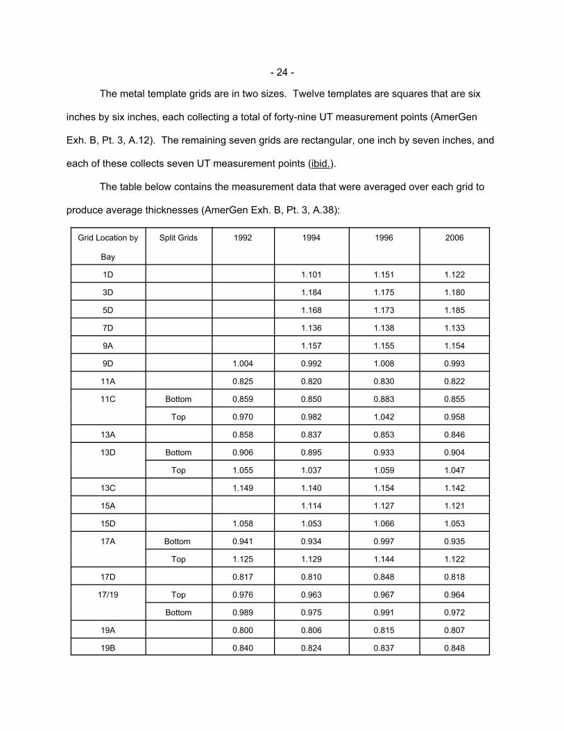
The metal template grids are in two sizes. Twelve templates are squares that are six
inches by six inches, each collecting a total of forty-nine UT measurement points (AmerGen
Exh. B, Pt. 3, A.12). The remaining seven grids are rectangular, one inch by seven inches, and
each of these collects seven UT measurement points (ibid.).
The table below contains the measurement data that were averaged over each grid to
produce average thicknesses (AmerGen Exh. B, Pt. 3, A.38):
Grid Location by
Bay
Split Grids 1992 1994 1996 2006
1D 1.101 1.151 1.122
3D 1.184 1.175 1.180
5D 1.168 1.173 1.185
7D 1.136 1.138 1.133
9A 1.157 1.155 1.154
9D 1.004 0.992 1.008 0.993
11A 0.825 0.820 0.830 0.822
11C Bottom 0.859 0.850 0.883 0.855
Top 0.970 0.982 1.042 0.958
13A 0.858 0.837 0.853 0.846
13D Bottom 0.906 0.895 0.933 0.904
Top 1.055 1.037 1.059 1.047
13C 1.149 1.140 1.154 1.142
15A 1.114 1.127 1.121
15D 1.058 1.053 1.066 1.053
17A Bottom 0.941 0.934 0.997 0.935
Top 1.125 1.129 1.144 1.122
17D 0.817 0.810 0.848 0.818
17/19 Top 0.976 0.963 0.967 0.964
Bottom 0.989 0.975 0.991 0.972
19A 0.800 0.806 0.815 0.807
19B 0.840 0.824 0.837 0.848
- 25 -
25 The thinnest average measurement of 0.800 inch existed over an area six inchesby six inches square. The AmerGen witness who performed the structural analysis attested –and Citizens’ witness did not dispute (Tr. at 479) (Hausler) – that properties varying over aregion of characteristic length less than 18 inches would not affect the structural analyses forthis shell (Tr. at 476) (Mehta). Thus, for the 0.800 inch measurement to be a valid measure ofthe remaining margin, it would have to extend over an area not less than approximately 18inches by 18 inches. No data has been presented to this Board indicating that such a largearea in the sand bed region is degraded to 0.800 inches on the average. Accordingly, whenAmerGen and the NRC Staff base their estimates of remaining margin on the assumed thick-ness of 0.800 inch, they are making a very conservative assumption.
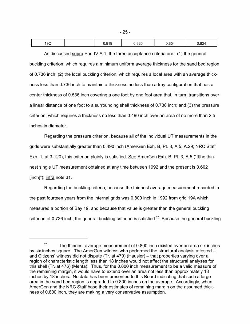
19C 0.819 0.820 0.854 0.824
As discussed supra Part IV.A.1, the three acceptance criteria are: (1) the general
buckling criterion, which requires a minimum uniform average thickness for the sand bed region
of 0.736 inch; (2) the local buckling criterion, which requires a local area with an average thick-
ness less than 0.736 inch to maintain a thickness no less than a tray configuration that has a
center thickness of 0.536 inch covering a one foot by one foot area that, in turn, transitions over
a linear distance of one foot to a surrounding shell thickness of 0.736 inch; and (3) the pressure
criterion, which requires a thickness no less than 0.490 inch over an area of no more than 2.5
inches in diameter.
Regarding the pressure criterion, because all of the individual UT measurements in the
grids were substantially greater than 0.490 inch (AmerGen Exh. B, Pt. 3, A.5, A.29; NRC Staff
Exh. 1, at 3-120), this criterion plainly is satisfied. See AmerGen Exh. B, Pt. 3, A.5 (“[t]he thin-
nest single UT measurement obtained at any time between 1992 and the present is 0.602
[inch]”); infra note 31.
Regarding the buckling criteria, because the thinnest average measurement recorded in
the past fourteen years from the internal grids was 0.800 inch in 1992 from grid 19A which
measured a portion of Bay 19, and because that value is greater than the general buckling
criterion of 0.736 inch, the general buckling criterion is satisfied.25 Because the general buckling
- 26 -
26 Because the UT measurements show that the buckling criteria are satisfied, therequirement that the drywell shell maintain a safety factor of 2.0 is satisfied (supra textaccompanying note 20).
27 Our conclusion that the sand bed region has an available margin of 0.064 inch isbased on the assumption that the entire sand bed region has a uniform thickness of 0.800 inch. Because all the other average grid measurements were greater than 0.800 inch, it may be seenthat our conclusion is based on a significantly conservative assumption. See AmerGen Exh. B,Pt. 3, A.31.
criterion is satisfied, there is no need to compare the grid measurements to the local buckling
criterion, which is likewise satisfied (AmerGen Exh. B, Pt. 3, A.5, A.15).26
Subtracting the general buckling criterion of 0.736 inch from the thinnest average
measurement recorded in the sand bed region (0.800 inch in Bay 19) results in a margin of
0.064 inch, which we conclude – based on the record evidence, including the fact that the
average thicknesses in the sand bed region remained virtually unchanged between 1992 and
2006 – will be the available margin when Oyster Creek enters the renewal period.27
b. External UT Measurements Support The Conclusion That The
Acceptance Criteria Are Satisfied. Over 100 UT measurements were taken in the sand bed
region from the exterior of the drywell shell during the 1992 and 2006 refueling outages. Unlike
the internal UT measurements, the external measurements were taken and evaluated as single
points, not as averaged grids. This is so because the single UT measurement points were
selected in 1992 based on a determination that they were among the thinnest (i.e., the most
corroded) locations in the sand bed region.
Two important requirements for a UT probe to provide an accurate measurement are
that (1) the surface area must be smooth over an area at least as large as the circular area of
the probe, and (2) the probe needs to sit perpendicular to the surface of the metal. To ensure
these two requirements were met, the metal at the individual points located throughout all ten
drywell bays was ground to be flat – removing about 0.10 to 0.20 inch of additional metal (Tr. at
- 27 -
28 This grinding occurred prior to coating the external wall of the sand bed regionwith epoxy (AmerGen Exh. B, Pt. 3, A.18).
29 Fewer measurements were taken in 2006 because some of the 1992 measure-ment points included two readings from the same location, and some of the locations of the1992 single point measurements could not be relocated (AmerGen Exh. B, Pt. 3, A.20). Topreclude this problem in the future, AmerGen in 2006 enhanced its techniques for identifying themeasurement locations (AmerGen Exh. B, Pt. 3, A.19).
30 These single UT measurements taken on the exterior of the shell were not aver-aged and compared to the general buckling criterion, because each point was selected basedon its thinness. Moreover, these points had to be ground flat to allow proper placement of theUT probe and, consequently, they were made even thinner by about 100 to 200 mils, or 0.10 to0.20 inch (Tr. at 604-05) (Polaski, Tamburro). These points are thus not representative of theoverall shell thickness and do not provide a basis for determining available buckling margin. Rather, they are representative of the most severely corroded areas, which were then thinnedeven further by the grinding process (Tr. at 603-04) (Polaski). An average of these measure-ments would reflect this bias, resulting in a skewed and unrealistic assessment of the shell. See AmerGen Exh. B, Pt. 3, A.22, A.23. Accordingly, these points are used to provide indi-vidual snapshot indicators of whether the shell complies with the pressure acceptance criterion,not to calculate available margin until the general buckling criterion is violated (AmerGen Exh.B, Pt. 3, A.30).
Citizens endeavored to rely on contour plots of the drywell shell’s sand bed region –which were generated by Dr. Hausler based on exterior UT measurements – to support theirargument that the available margin is less than 0.064 inch (Citizens Exh. C.1, Attachment 1;Citizens Exh. B, A.14). This they may not do, because relying on these contour plots to
(continued...)
604-05) (Polaski, Tamburro) – over an area of about two inches in diameter to allow the UT
probe to sit on a smooth surface perpendicular to the shell.28 To perform UT measurements on
a grid on the external wall would have required grinding much larger areas (six inches by six
inches or larger), which would have resulted in unnecessarily reducing the thickness of the
drywell shell in areas that had already been determined to be among the thinnest. See
AmerGen Exh. B, Pt. 3, A.16 to A.18.
In 1992 Oyster Creek took over 120 single point UT measurements, and in 2006 it took
single point UT measurements from 106 of the previously measured locations (AmerGen Exh.
B, Pt. 3, A.20).29 These individual points were compared to, and satisfied, the pressure
criterion. See AmerGen Exh. B, Pt. 3, A.21, A.29.30
- 28 -
30(...continued)determine Oyster Creek’s acceptance criteria is effectively an attack on the derivation of OysterCreek’s CLB and, thus, beyond the scope of this proceeding (supra note 19). In any event, wefind that the contour plots are not reliable representations of the condition of the drywell shell,because they are based on the exterior UT measurements, which are significantly biased in thethin direction (see AmerGen Exh. C, Pt. 2, A.7; AmerGen Exh. C, Pt. 3, A.10, A.40; NRC StaffExh. C, A.26, A.27, A.12(d)).
31 Because the area in which this 0.602 inch measurement was taken had beenground thinner by about 0.10 to 0.20 inch to allow for accurate UT measurements (supra note30), it becomes clear that this “thinnest” external single point measurement is conservative inthe extreme. Taking the grinding into account, the actual thickness of that point is somewherein the range of 0.702 to 0.802 inch, which means that the margin to the pressure criterion is inthe range of 0.212 to 0.312 inch.
Specifically, with regard to the pressure criterion, the thinnest external single point
measurement is 0.602 inch in Bay 13, which is 0.112 inch thicker than required by the pressure
criterion of 0.490 inch.31 Because the available margin of 0.112 inch for the pressure criterion
(which is based on the thinnest external single point measurement) is greater than the available
margin of 0.064 inch for the general buckling criterion (which is based on the thinnest interior
average grid measurement in Bay 19 (supra Part IV.A.2.a)), the external single point measure-
ments support the conclusions that (1) the acceptance criteria are satisfied, and (2) the bound-
ing margin for purposes of this proceeding is the general buckling criterion margin of 0.064 inch
(AmerGen Exh. B, Pt. 3, A.32; accord NRC Staff Exh. 1, at 4-57 to 4-60).
B. AmerGen’s UT Program Provides Reasonable Assurance That The Sand BedRegion Will Not Violate The Acceptance Criteria During The Renewal Period,Because The Record Shows That Corrosion Has Effectively Been Arrested
Citizens assert that the exterior and interior walls of the drywell shell in the sand bed
region will likely experience significant corrosion during the renewal period due to the existence
of a continuing corrosive environment.
We agree with AmerGen and the NRC Staff that Citizens’ argument is insubstantial.
Based on the exhibits and testimony, we find there is reasonable assurance that the exterior
wall in the sand bed region will not experience any significant corrosion during the renewal
- 29 -
32 Testimony regarding the potential for future corrosion was presented over thecourse of two panels: Panel 4 (Sources of Water) and Panel 5 (The Epoxy Coating). Citizenspresented one witness, Dr. Rudolf H. Hausler. AmerGen presented eleven witnesses: (1) Mr.Jon R. Cavallo; (2) Mr. Scott R. Erickson; (3) Mr. Michael P. Gallagher; (4) Mr. Barry Gordon;(5) Mr. Jon C. Hawkins; (6) Mr. Edwin Hosterman; (7) Mr. Martin E. McCallister; (8) Mr. John F.O’Rourke; (9) Mr. Ahmed Ouaou; (10) Mr. Francis H. Ray; and (11) Mr. Peter Tamburro. TheNRC Staff presented five witnesses: (1) Mr. Hansraj G. Ashar; (2) Dr. James A. Davis; (3) Dr.Mark Hartzman; (4) Mr. Timothy L. O’Hara; and (5) Mr. Arthur D. Salomon.
period because: (1) the refueling cavity liner is the only known source of water onto the exterior
wall in the sand bed region, and AmerGen’s corrective actions have adequately mitigated that
leakage; and (2) even if water entered the exterior wall in the sand bed region, the drywell shell
will be adequately protected by the shell’s robust epoxy coating. We also find that the interior
wall in the sand bed region will not experience significant corrosion during the renewal period,
because there is no evidence of measurable past corrosion there, and the record reveals that
the environment is benign and will not pose a serious threat of future corrosion.32
1. It Is Highly Unlikely There Will Be Future Corrosion On TheExterior Wall In The Sand Bed Region
Citizens argue that future corrosion will likely occur on the exterior wall of the drywell
shell in the sand bed region because (Citizens’ Response to AmerGen and NRC Staff Initial
Testimony at 18-23 (Aug. 17, 2007)): (1) there are potential sources of water other than the
refueling cavity liner, and AmerGen has been unable to stem water leakage from the refueling
cavity liner in any event; and (2) the epoxy coating likely contains defects that could allow
corrosion to develop, or that could cause the coating to rapidly deteriorate during the period of
extended operation. We disagree.
a. AmerGen Has Taken Effective Steps To Eliminate Corrosion-
Causing Moisture On The Exterior Wall Of The Sand Bed Region. Citizens dispute
whether the refueling cavity liner – which is filled with water during refueling outages and other
rare outages in which the reactor vessel must be opened – has been established as the only
- 30 -
source of water on the exterior portion of the drywell shell in the sand bed region. According to
Citizens, documentation from AmerGen establishes that the Oyster Creek equipment pool has
leaked and “fuel pool water that did not originate from the refueling cavity has been found in the
sand bed region” (Citizens Exh. 37, Overview of the Relevant Facts Regarding Corrosion of the
Drywell Shell at the Oyster Creek Nuclear Generating Station at 17 (initially submitted as
Citizens Exh. B, Att. 5 (July 20, 2007)). Citizens’ witness, Dr. Hausler, observed that “a number
of potential sources of water . . . have been identified by the reactor operator, including the
refueling cavity [and] the equipment pool” (Citizens Exh. B, A.17). In addition, Dr. Hausler, in
his written testimony, asserted there is a potential for condensation to form on the exterior wall
of the sand bed region due to AmerGen’s “use of drywell chillers, which are used during
refueling and other outages when access to the drywell is needed” (Citizens Exh. C, A.20)
(citing AmerGen Exh. B, Pt. 4, A.15). This is “apparently confirmed,” he added, “by an analysis
of water that had drained from the exterior of the sand bed region before March 2006, which
showed no activity” (ibid.) (citing Citizens Exh. 23, AmerGen Drywell Inspection Leakage Plan);
see also Citizens Exh. B, A.17; Citizens Exh. 12, Memorandum from Dr. Rudolf H. Hausler to
Richard Webster, Esq. at 8 (Apr. 25, 2007). Because of this alleged uncertainty as to “where
the water may be coming from,” Dr. Hausler stated that “one can safely assume that water could
be present at some time in the future and at least during each outage” (Citizens Exh. 12, at 8).
Dr. Hausler’s arguments are refuted by the record.
During the late 1980s and early 1990s, the then-licensee of Oyster Creek conducted
“[e]xtensive investigations of a large number of other plant components . . . [to] provide
reasonable assurance that these components are not sources of water in the sand bed region”
(AmerGen Exh. B, Pt. 4, A.13). Specifically, the following components were eliminated as
potential sources of water in the sand bed region: “the bellows seal at the bottom of the
refueling cavity, . . . the refueling cavity drain line, the refueling cavity metal trough and its
- 31 -
33 Notably, at the hearing, Dr. Hausler conceded that the only historical source ofwater that caused a corrosive environment in the drywell shell was leakage from the refuelingcavity (Tr. at 687). Although Dr. Hausler’s concession renders nugatory Citizens’ argumentsabout other potential sources of water, we nevertheless address those arguments and rejectthem as meritless.
34 We reject Citizens’ allegation (Citizens Exh. 37, at 17) that Citizens Exhibit 21demonstrates there has been leakage from the equipment pool onto the external wall of thedrywell shell in the sand bed region. Rather, we find that the record supports the conclusionthat the leakage described in Citizens Exhibit 21 “is isolated from the drywell shell and, basedon the physical configuration of [Oyster Creek], there is no credible leakage path from theunderside of the equipment pool to the drywell shell” (AmerGen Exh. C, Pt. 4, A.9). We likewisereject Citizens’ claim (Citizens Exh. 37, at 17) that fuel pool water that did not originate from therefueling cavity has been found in the sand bed region. The author of Citizens Exh. 22,Technical Data Report (“TDR”) 964, Drywell Sand Bed Drain Leakage (Mar. 3, 1989)), uponwhich Citizens rely, “proposes that the water discovered might have been ‘old’ fuel pool water,i.e., water left over from a previous refueling outage, when the refueling cavity was filled withwater” (AmerGen Exh. C, Pt. 4, A.13). Although analysis of water samples collected from eachbay drain proved inconclusive, following the TDR, the then-licensee conducted extensiveinvestigations that “ultimately found no source of leakage other than the refueling cavity liner”(ibid.).
associated gasket, . . . the concrete trough located below the metal trough, the refueling cavity
steps, the equipment pool and refueling cavity skimmer systems, the equipment pool liner,
drain, and support pad, the spent fuel pool liner, and piping buried in concrete” (ibid.) (citations
omitted); see also Citizens Exh. 21, Letter from J.C. DeVine, Jr., GPU Nuclear, to U.S. NRC
(Dec. 5, 1990), Att. III, GPUN Detailed Summary Addressing Water Intrusion and Leakage
Effects Related to the Oyster Creek Drywell. When the Board questioned Dr. Hausler during
the hearing, he indicated that he had no evidence of a source other than the refueling cavity as
causing water to be present on the external shell. See Tr. at 698.33 Because Citizens failed to
present any probative evidence supporting their assertion about an alternate source of water
leaking onto the sand bed region, we find that the only source of water leaking onto the sand
bed region is the refueling cavity liner. See Tr. at 384-85, 799.34
With respect to the potential for condensation to occur on the exterior sand bed region,
condensation occurs only when the drywell shell is cooler than the surrounding air. Because
- 32 -
35 Although Dr. Hausler’s written rebuttal testimony disputed the evaporation rate ofcondensation in the sand bed region presented by AmerGen’s expert, Mr. Gordon, we view Dr.Hausler’s subsequent testimony at the hearing (Tr. at 687) as negating, and withdrawing,Citizens’ argument that condensation on the exterior of the drywell shell is a potential source ofcorrosion. Even if we were to consider Dr. Hausler’s written rebuttal testimony, however, wewould give no weight to his unsupported assertion that Mr. Gordon did not “use[ ] a reasonableapproach to estimate the time in which any water on the exterior of the shell would evaporate”(Citizens Exh. C, A.22). Dr. Hausler failed to provide any probative evidence in support of hisbare assertion that the sand bed region has a limited air exchange, which would cause anywater in the sand bed region to become fully saturated during the outage. See, e.g., CitizensExh. 39, Memorandum from Dr. Rudolf Hausler, to Richard Wester, Esq., at 19 (Aug. 16, 2007)(speculating that “the former sand bed area . . . is a totally stagnant space”); cf. AmerGen Exh.C.1, Pt. 6, A.8 (“[t]he gaps between the vent headers and the concrete provide substantial areafor air flow, as do many piping penetrations from the drywell”); accord Tr. at 771-72 (Gallagher).
the “reactor pressure vessel and other equipment located inside the drywell generate a signifi-
cant amount of heat,” the drywell shell is heated to temperatures “significantly above the Reac-
tor Building ambient temperature. This temperature differential will prevent condensation from
forming on the exterior of the drywell shell in the sand bed region” (AmerGen Exh. B, Pt. 4,
A.14). Although it is possible for condensation to occur during an outage due to the use of
drywell chillers – which are used during outages when extended access to the drywell is
required (AmerGen Exh. B, Pt. 4, A.15) – “such postulated condensation would only last until
restart, when the drywell shell temperature would rise and any water would evaporate”
(AmerGen Exh. B, Pt. 4, A.15). During the 2006 outage, AmerGen reported no evidence of
condensation on the exterior of the drywell shell in the sand bed region (AmerGen Exh. B, Pt. 4,
A.16). Significantly, Dr. Hausler testified at the hearing that he did not believe that “condensa-
tion on the [exterior of the drywell shell] is really a source of water that we might have to worry
about” (Tr. at 687). We agree. The evidence shows that condensation can not occur during
normal operations, and during outages, any condensation that could form due to the use of
drywell chillers would evaporate before posing a corrosion risk. See AmerGen Exh. B, Pt. 4,
A.14 to A.17.35
- 33 -
36 During the evidentiary hearing, AmerGen attested (Tr. at 696-97) (O’Rourke),and the NRC Staff agreed (Tr. at 697) (Ashar), that AmerGen’s commitment consisted ofapplying stainless steel tape and a strippable coating to the refueling cavity liner during everyoutage – scheduled and unscheduled alike – when the refueling cavity is flooded. Given thisunequivocal commitment, we summarily reject Citizens’ assertion that AmerGen may flood the
(continued...)
Citizens also argue that the corrective actions AmerGen has taken to ensure the
refueling cavity will not leak into the sand bed region – i.e., repair and monitoring of the
collection trough and application of stainless steel tape and strippable coating during outages –
are ineffective (Citizens Exh. C.1, A.25). This argument cannot be reconciled with the record.
After corrosion was discovered on the exterior of the drywell shell in the sand bed
region, the then-licensee of Oyster Creek took multiple corrective actions, including (AmerGen
Exh. B, Pt. 1, A.23): (1) clearing the sand bed drains; (2) repairing the leakage collection trough
“to minimize the possibility of water escaping the trough and entering the area between the
concrete shield wall and exterior drywell shell” (AmerGen Exh. B, Pt. 4, A.8); (3) clearing the
trough drain; and (4) applying stainless steel tape and a strippable coating to the refueling cavity
during refueling outages. AmerGen witnesses testified that during the 2006 refueling outage,
“[n]o water was observed on the exterior of the drywell shell in the sand bed region, or in [or
from] the sand bed drains” (AmerGen Exh. B, Pt. 4, A.10). Messrs. Hawkins and Erickson
confirmed they personally entered the sand bed regions in nine of the bays during the 2006
outage “and did not see water either on the exterior of the drywell shell, or on the concrete floor
of the sand bed region” (AmerGen Exh. B, Pt. 4, A.11).
AmerGen has committed to apply the measures utilized during the 2006 outage at every
outage during the renewal period when the refueling cavity is flooded. First, AmerGen will apply
stainless steel tape and a strippable coating to the refueling cavity liner prior to flooding the
refueling cavity. See AmerGen Exh. 10, Commitment 27(2); AmerGen Exh. B, Pt. 1, A.14; Tr. at
696-97.36 Second, AmerGen will verify that the “refueling cavity concrete trough drain [is] . . .
- 34 -
36(...continued)refueling cavity without applying leakage mitigation measures during a forced outage (CitizensExh. C, A.20).
clear from blockage once per refueling cycle[, and a]ny identified issues will be addressed via
the corrective action process” (AmerGen Exh. 10, Commitment 27(13)). Third, AmerGen will
monitor the refueling cavity seal leakage trough drains and the drywell sand bed region drains
for leakage. The sand bed region drains will be monitored daily during refueling outages and
quarterly during the operating cycle. “If leakage is detected, procedures will be in place to
determine the source of leakage and investigate and address the impact of leakage on the
drywell shell,” and appropriate corrective actions will be taken (AmerGen Exh. 10, Commitment
27(3)); see also NRC Staff Exh. B, A.12(b). Additionally, at the hearing, AmerGen represented
it would expand this commitment to include periodic inspections of the sand bed drains for
blockage. See Tr. at 843-44; supra note 12.
Citizens raise two challenges to the above mitigation measures. First, Dr. Hausler
asserts the leakage collection trough “was damaged. . . . and was seen to be far from ideal in
the most recent outage” (Citizens Exh. C, A.20). If the trough degraded further, he states, water
could enter the drywell again and create a corrosive environment (ibid.). We reject Dr.
Hausler’s conjectural concern. He fails to cite any evidence demonstrating defects in the trough
as of the 2006 refueling outage; rather, the exhibits on which he relies are from 1986 and 1996.
See ibid. (citing Citizens Exhs. 48, 49). Nor does he provide evidentiary support for his
speculation that the trough could degrade further or that undetected clogging of any drains
could recur. See ibid.; Citizens Exh. B, A.18. AmerGen has committed to verify that the
“refueling cavity concrete trough drain [is] . . . clear from blockage once per refueling cycle,” and
to monitor the refueling cavity seal leakage trough drains for leakage (AmerGen Exh. 10,
Commitment 27(3), (13)). And AmerGen also has committed to verify periodically that the sand
- 35 -
bed drains are unclogged and exhibit no evidence of leakage (id., Commitment 27(3)). “Any
identified issues will be addressed via the corrective action process” (id., Commitment 27(13);
see also id., Commitment 27(3)), thereby providing reasonable assurance there will be no
corrosive environment on the exterior wall in the sand bed region.
Second, Citizens assert that the “metal tape and strippable coating is not always effec-
tive in preventing significant leaks” (Citizens Exh. C.1, A.25). Citizens do not allege the tape
and coating were ineffective during the 2006 outage; rather, they rely on a February 1, 1993
memorandum that addressed leakage from the refueling cavity liner onto the sand bed region
during the 1992 refueling outage. Although Citizens are correct that there was leakage from the
refueling cavity liner during the 1992 outage notwithstanding the use of the tape and coating,
they ignore that this outage was prior to the then-licensee’s repair of the leakage collection
trough and the concrete trough drain. See Citizens Exh. 50, Internal GPU Nuclear Memoran-
dum, Re: 14R Reactor Cavity Leak Detection Effort, at 2 (Feb. 1, 1993) (“[s]everal areas con-
sidered having the highest potential for being a leak were repaired or are scheduled for repair
prior to the next cavity flood up”). Since the 1992 outage, the troughs have been repaired, and
AmerGen’s use of the tape and coating during the 2006 outage not only “reduced the amount of
[refueling] cavity liner leakage,” it eliminated leakage on the external wall in the sand bed region
(AmerGen Exh. B, Pt. 4, A.9). The fact that no water was discovered in the sand bed region
during the 2006 outage when the tape and coating were used defeats Citizens’ assertion that
these leakage-mitigation measures are ineffective.
Further, although Citizens correctly observe that the leakage from the refueling cavity
liner during the 2006 outage – approximately one gallon per minute (AmerGen Exh. B, Pt. 4,
A.9) – demonstrates that AmerGen “has not yet devised a means of preventing the reactor
fueling cavity from leaking” (Citizens Exh. 37, at 17), this fact is not critical to our resolution of
the contention presented. Rather, the salient question is whether water will leak from the
- 36 -
37 Citizens correctly observe that in 2006, AmerGen discovered the followingindications that water had been present in the sand bed region: (1) white discoloration wasseen on the concrete floor, which appeared to be residue left behind by water; and (2) waterwas found in three of the five plastic bottles that collect water from the sand bed drains. Basedon the totality of the evidence, we accept AmerGen’s explanation that these were hoaryindicators of long-past leakage, “because the plastic drain lines from the sand bed drains weredry and there was no water on the Torus Room floor” (AmerGen Exh. B, Pt. 4, A.12; CitizensExh. 37, at 17).
38 This conclusion takes into account our subsequent finding (infra Part IV.B.2) thatthere will likewise be no measurable corrosion on the interior wall of the drywell shell in the sandbed region during the renewal period.
refueling cavity liner at a sufficient rate to overwhelm the trough and drains and enter onto the
exterior wall in the sand bed region, thereby creating a corrosive environment. The record
requires that we answer that question in the negative. As AmerGen explained, “[l]eakage from
the [refueling] cavity is not relevant unless it exceeds the capacity of the trough drain” (Amer-
Gen Exh. C, Pt. 4, A.14). The one gallon per minute leakage observed during the 2006 outage
“is well within the capacity of the refueling cavity trough drain system, which is estimated using
standard hydraulic principles to be approximately 50 gallons per minute” (AmerGen Exh. B, Pt.
4, A.9). The trough drain system directed the leakage into the controlled drainage collection
system, thus preventing it from reaching the drywell shell, much less the sand bed region.37
The Board therefore finds that: (1) AmerGen has demonstrated that the refueling cavity
liner is the only source of corrosive-causing water on the external wall of the drywell shell in the
sand bed region; (2) AmerGen’s commitments effectively eliminate the potential for water
leakage from the refueling cavity liner into that area; and (3) in the absence of such water, there
will be no further corrosion in that area. Absent further corrosion, the thickness of the shell in
the sand bed region will not violate the acceptance criteria during the renewal period, and
Citizens’ challenge to the frequency of AmerGen’s UT program must be rejected.38
- 37 -
39 ASME Section XI, Subsection IWE criteria require direct visual inspection of theentire exterior surface, from the base of the sand bed floor (approximately elevation 8'11") to thetop where the drywell shell rises into the 3" gap with the concrete (approximately elevation12'3") (see AmerGen Exh. B, Pt. 5, A.22).
b. Even If Water Entered The Exterior Wall Of The Drywell Shell, The
Sand Bed Region Is Protected From Further Corrosion By A Robust, Triple-Layered
Epoxy Coating. During the 1992 refueling outage, the then-licensee of Oyster Creek applied
to the drywell shell in the sand bed region a one hundred percent solid, three-layer epoxy
coating system – consisting of one pre-prime and two additional coats – to prevent corrosion
from forming on the metal surface of the drywell shell in the event water were to reach the sand
bed region. See AmerGen Exh. B, Pt. 5, A.6; NRC Staff Exh. B, A.14. AmerGen has committed
to visually inspect the epoxy coating in all ten drywell bays prior to the period of extended opera-
tion and every other refueling outage thereafter (AmerGen Exh. 10, Commitment 27(4)),
employing a Protective Coating Monitoring and Maintenance Program that “incorporate[s]
coated surfaces inspection requirements specified in ASME Code Section XI, Subsection IWE”
(NRC Staff Exh. B, A.15).
Specifically, AmerGen’s epoxy coating program requires it to: (1) examine the inspected
areas “for evidence of flaking, blistering, peeling, discoloration, and other signs of distress”;39 (2)
resolve by engineering evaluation, or correct by repair or replacement, any suspect areas in
accordance with IWE-3122; and (3) perform, when specified as a result of engineering evalua-
tion, supplemental examinations in accordance with IWE-3200 (NRC Staff Exh. 1, at 3-120; see
also NRC Staff Exh. B, A.15). If the epoxy coating is damaged and corrosion is observed,
AmerGen must conduct UT measurements of the affected area and evaluate the results per its
existing program. See NRC Staff Exh. B, A.15 (citing AmerGen Exh. 10, Commitment 27(1)).
The NRC Staff concluded that AmerGen’s commitments will “provide[ ] assurance that effects of
- 38 -
40 In his pre-filed rebuttal testimony, Dr. Hausler stated that “documents [he has]received from AmerGen indicate that areas of the shell in the sand bed region were not coatedwith epoxy because they are inaccessible” (Citizens Exh. C, A.21). But the documents reliedupon by Dr. Hausler – Citizens Exhibits 40 and 41 – fail to support his allegations. See CitizensExh. 40, E-mail from John G. Hufnagel, Jr., to Ahmed Ouaou and Donald B. Warfel, Sr., Re:
(continued...)
aging will be adequately managed so that intended functions will be maintained throughout the
renewal period” (ibid.) (citing NRC Staff Exh. 1, at 3-114 to 3-143, 3-163 to 3-167).
Citizens nevertheless assert that if any water is present on the exterior sand bed region
during the period of extended operation, the epoxy coating system will not adequately protect
against corrosion, because: (1) inaccessible areas of the drywell shell in the sand bed region
were not coated (Citizens Exh. C, A.21; Tr. at 707); (2) water could penetrate through defects in
the epoxy that likely formed when the coating was applied (Citizens Exh. B, A.21; Tr. at 721); (3)
visual observation may not be sufficient to detect the early stages of coating failure (Citizens
Exh. B, A.21; Tr. at 739); and (4) the epoxy coating might rapidly deteriorate between scheduled
inspections (Citizens Exh. B, A.21; Tr. at 730, 733-35). None of these arguments has merit.
First, contrary to Citizens’ argument, we conclude that ample record evidence shows
that the entire sand bed region is coated with the protective three-layer epoxy coating.
AmerGen witness Mr. Cavallo attested that “workers who inspected the external coating in all
ten bays during the 2006 refueling outage confirmed that all of the areas were coated”
(AmerGen Exh. C.1, Pt. 5, A.6). See also Tr. at 706 (Hawkins) (AmerGen witness testifies that
the entire sand bed region, “from 8 foot 11 [inches] to 12 foot 3 inches . . . is completely coated”
with the epoxy). Likewise, NRC Staff witness Mr. O’Hara testified that, based on his first-hand
knowledge from inspecting two bays during the 2006 outage, “[a]ll the regions on the outside of
the drywell were coated” (Tr. at 718). We find that this evidence, which includes convincing
eye-witness testimony, negates Citizens’ bare assertion that a portion of the sand bed region is
not protected by epoxy.40
- 39 -
40(...continued)Challenge Board #1 additional comment (Nov. 30, 2006, 10:41); Citizens Exh. 41, TechnicalFunctions Safety/Environmental Determination and 50.59 Review (EP-016), Clean and CoatDrywell Ext. In Sand Bed (Jan. 5, 1993). Neither Exhibit 40 nor 41 indicates that actual areas ofthe sand bed region were left uncovered (AmerGen Exh. C.1, Pt. 5, A.6). Citizens Exhibit 40 “isbased entirely on a historical document that pre-dated the cleaning and coating of the exteriorshell” (ibid.), and Citizens Exhibit 41, which was written in December 1992, merely conjecturesthat “‘patches of the drywell exterior may be left uncleaned and/or uncoated’” (ibid.) (quotingCitizens Exh. 41, at OCLR00022257). We find these speculative documents to be uncon-vincing, and we credit, instead, the testimony of AmerGen and NRC Staff witnesses who aver-red, based on first-hand knowledge, that the drywell shell in the sand bed region is completelycoated with the three-layer epoxy coating.
41 Citizens’ witness, Dr. Hausler, conceded that he was unaware that the epoxycoatings contained no solvents (Tr. at 748). Although Dr. Hausler speculated that the viscous
(continued...)
Second, we reject Citizens’ assertion that the epoxy likely contains defects – i.e.,
pinholes or holidays – that formed when the coating was applied and through which water could
penetrate. A pinhole or holiday is a microscopic, localized defect in the epoxy coating that is
created “by the chemistry of the coating (e.g., solvent entrapment)” or due to a problem in the
original application of the coating, “such as failure to properly cure the coating”; they are not
defects caused by degradation of the coating over time (AmerGen Exh. B, Pt. 5, A.13). Dr.
Hausler opines that pinholes may have been present in the coating when it was applied. See
Citizens Exh. B, A.21. As a consequence of these defects, he asserts, “any water in the sand
bed can penetrate the coating . . . [which] would then reach [the] steel interface beneath the
coating and cause further corrosion” (Citizens Exh. B, A.21).
Citizens’ argument fails to recognize that the nature of the epoxy coating at Oyster
Creek minimizes the likelihood of pinholes and the infiltration of water for two reasons. First, the
formation of pinholes “has to do with solvent migration leaving very small holes in the coating,”
but the epoxy coating at Oyster Creek has “no solvents in any one of the three coats” (Tr. at
724) (Cavallo). See also AmerGen Exh. 35, Application Guide for DEVOE Coatings Pre-Prime
167 and Devran-184 (indicating both the pre-prime and top coats are 100 percent solids).41
- 40 -
41(...continued)composition of solvent-free epoxy makes it more difficult for air bubbles to escape (ibid.), heprovided no information that would lead the Board to question the persuasive testimony of theAmerGen and NRC Staff witnesses regarding the robust nature of the coating. Mr. Cavallo alsotestified that – contrary to Dr. Hausler’s assertion (Tr. at 721) – dust in the atmosphere at theapplication stage is not a material causative factor of pinholes in this type of epoxy coating (Tr.at 724).
42 Notably, in Dr. Hausler’s pre-filed written submission, he conceded that “pinholesare rare when two coats of . . . [epoxy coating] have been applied” (Citizens Exh. 39, at 17). Moreover, when questioned by the Board, Dr. Hausler acknowledged he knows of no evidencein the record that would suggest the existence of any pinholes in the Oyster Creek epoxycoating (Tr. at 722).
43 VT-1 inspectors are trained and qualified in accordance with ASME Section XI,Subsection IWE to “inspect surfaces such as the drywell shell for evidence of flaking, blistering,peeling, discoloration, and other signs of degradation that would be early signs of potentialcoating failure” (AmerGen Exh. B, Pt. 5, A.12).
Second, because the epoxy coating is a three-layer system, “[i]f a pinhole or holiday exists in
the primer coat, it would likely be covered up by the second coat. The likelihood that a pinhole
or holiday would extend through both coats is quite small [and t]he likelihood that a pinhole or
holiday would extend through all three coats . . . is even smaller” (AmerGen Exh. B, Pt. 5, A.14);
see also NRC Staff Exh. B, A.14.42
Beyond preventing the formation of pinholes and the infiltration of water in the first
instance, the epoxy coating system applied to the Oyster Creek drywell shell also allows for
easy detection of signs of deterioration through the use of contrasting pigments in the top two
layers. See AmerGen Exh. B, Pt. 5, A.6. Because the early indications of epoxy coating failure
include pinpoint rusting and rust staining (AmerGen Exh. C, Pt. 5, A.7), the “grayish white” top
coat of the epoxy will provide “a very good visual contrast to . . . [the] iron oxide or red rust, . . .
[which] would be very visible to, particularly, trained [Visual Testing (“VT”)]-1 inspectors” (Tr. at
725) (Cavallo).43 See also id. at 722-23 (Cavallo); AmerGen Exh. B, Pt. 5, A.16; NRC Staff Exh.
C, A.36 (“early stages of coating failure would be apparent during a VT-1 inspection,” because
the resulting “film will be rust colored and will be obvious against the grey colored epoxy
- 41 -
coating”); NRC Staff Exh. B, A.15. Had there been any pinholes in the coating, the corrosion
that would have resulted from water that was present in the sand bed region during the 1994
and 1996 refueling outages – when the strippable coating was not used in the refueling cavity
liner – “would be visible today due to the volume of corrosion products (iron oxides) and surface
rust staining caused by the corrosion process” (AmerGen Exh. B, Pt. 5, A.14).
In addition to surface discoloration, because iron oxide corrosion products occupy a
volume “between approximately seven and ten times greater than the metal being corroded,” if
corrosion were occurring under the epoxy coating, the metal surface would become very
uneven (AmerGen Exh. B, Pt. 6, A.8; see also Tr. at 726 (Cavallo); NRC Staff Exh. B, A.15).
Specifically, the corrosion would generate “an irregularly shaped fairly circular rough surfaced
deformation of the coating . . . centered on the area of the pinhole,” known as a “carbuncle” (Tr.
at 726-27 (Cavallo); see also AmerGen Exh. B, Pt. 5, A.15). However, in a benign environment,
such as the Oyster Creek drywell, if there were pinholes in each of the three layers of epoxy
coating, and if all three pinholes were aligned, AmerGen testified that it would “[not] expect to
see carbuncles[, rather it] . . . would expect to see [only staining] over a period of three or four
years, which is the frequency of inspection” (Tr. at 727) (Cavallo).
Significantly, AmerGen’s visual inspection of the epoxy coating on the drywell shell in the
sand bed region during the 2006 refueling outage confirmed that neither of the key indicators of
corrosion was present. Messrs. Erickson and Hawkins – both of whom are certified VT-1
inspectors (AmerGen Exh. B, Pt. 4, A.3; supra note 43) – testified that during the 2006 outage
they collectively inspected nine of the ten bays (AmerGen Exh. B, Pt. 4, A.18, A.19), and they
found no evidence of “any flaking, chipping, blistering, peeling, pinpoint rusting, cracking,
chalking or discoloration, or any evidence of corrosion or corrosion products from the exterior
drywell shell in the sand bed region. . . . There was a visible shine indicative of a coating in
pristine condition” (AmerGen Exh. B, Pt. 4, A.23; see also Tr. at 723 (Hawkins, Erickson);
- 42 -
44 Because Dr. Hausler is not familiar with the specific composition of epoxy in useat Oyster Creek (Tr. at 734-35) (Hausler)), and because his expertise in oil field applications (Tr.at 667 (Hausler)) – which “generally involve continuous immersion service with highly corrosive
(continued...)
AmerGen Exh. 24, ASME IWE (Class MC) Containment Visual Examination Record (Oct. 22,
2006)). Likewise, NRC Staff witness Mr. O’Hara testified that during the 2006 refueling outage
he physically inspected the external epoxy coating on the outside of the drywell shell in two of
the bays, and the coating “appeared to be in excellent condition with no visible evidence of
cracking, peeling, or blistering” (NRC Staff Exh. B, A.20). After reviewing video tapes of all the
other bays along with the data sheets for each bay, Mr. O’Hara testified the tapes “showed the
same general condition in all bays and showed that the epoxy coating had not been visibly
disturbed since the original application” (ibid.; see also Tr. at 723 (Cavallo) (testifying that there
are no “visual indications of pinholes, . . . [which] allows me to state unequivocally we do not
have pin holes in the coatings applied to the drywell in 1992”)).
In short, we find that overwhelming record evidence supports the conclusion that –
contrary to Citizens’ assertion – there are no pinholes in the protective epoxy coatings, much
less pinholes in each of the three layers that are aligned and through which water has
penetrated, or will likely penetrate.
Nor do we accept Citizens’ argument that visual inspections may not reliably detect the
early stages of coating failure. Dr. Hausler contends that “[o]nce a defect . . . provides access
for water to the steel surface underneath, corrosion begins slowly,” and although “hardly
noticeable from the surface . . . as corrosion progresses the coating will start to crack, opening
up a larger defect” (Citizens Exh. 12, at 9; see also Citizens Exh. 39, at 19-20). Dr. Hausler
thus criticizes AmerGen’s proposed four-year inspection cycle as inadequate, because “damage
might occur between inspections” (Citizens Exh. 12, at 8). Dr. Hausler’s unsupported allega-
tions are not credible.44
- 43 -
44(...continued)pressurized fluids, corrosive gases and continuous fluid flow” (AmerGen Exh. C, Pt. 5, A.5) – isinapplicable to the benign operating environment at Oyster Creek, we accord diminished weightto his assertions attacking the reliability of AmerGen’s coating inspection program.
45 According to Mr. Cavallo, a recent Electric Power Research Institute study onwhich he served as a principal investigator “confirms that visual inspections would detect theearly signs of coating system failure” (AmerGen Exh. C, Pt. 5, A.6).
46 To the extent Dr. Hausler suggests that AmerGen should use alternative meansfor monitoring the epoxy coating – e.g., “electric and sponge type surface examinations” (Tr. at739) (Hausler) – he is introducing concerns beyond the scope of this proceeding. See Tr. at739-40 (Chairman Hawkens); LBP-06-22, 64 NRC at 244-48 (rejecting Citizens’ challenge toAmerGen’s monitoring of the coating in the sand bed region).
The “use of visual inspections to detect coating failures . . . is based . . . on established
industry practice” (AmerGen Exh. C, Pt. 5, A.6), and has been endorsed by the NRC in the
Generic Aging Lessons Learned (“GALL”) Report, NUREG-1801, Vol. 2, Section XI.S1 (NRC
Staff Exh. B, A.15). In addition, NRC Regulatory Guide 1.54, Rev. 1, Service Level I, II, and III
Protective Coatings Applied to Nuclear Power Plants “recommend[s] visual inspection of
coatings for evidence of degradation before conducting additional tests” (ibid.; see also LBP-06-
22, 64 NRC at 245).45 AmerGen’s Protective Coating Monitoring and Maintenance Program
follows the NRC Staff guidance set forth in the GALL Report, and satisfies the requirements of
ASME Code Section XI, Subsection IWE, which is mandated by 10 C.F.R. § 50.55a. See
AmerGen Exh. C, Pt. 5, A.6; NRC Staff Exh. B, A.13, A.15; LBP-06-22, 64 NRC at 247;
see generally NRC Staff Exh. 2, Subsection IWE Requirements for Class MC and Metallic
Liners of Class CC Components of Light-Water Cooled Plants (1992).46
We therefore reject Citizens’ assertion that visual inspections may not be sufficient to
detect the early stages of coating failure. The record shows that “early indications of epoxy
coating failure . . . include pinpoint rusting and rust staining, long before widespread coating
failure in the form of cracking and delamination” (AmerGen Exh. C, Pt. 5, A.7). Because these
early indications of coating failure would develop at a “very slow rate” in the “benign non-
- 44 -
immersion environment” of the sand bed region (ibid.), we find that AmerGen’s commitment to
conduct visual inspections of the epoxy coating every four years provides reasonable assurance
that early stages of coating failure will be detected. See NRC Staff Exh. B, A.15; see also
AmerGen Exh. C, Pt. 5, A.7 (“Dr. Hausler’s speculation about the inability of visual inspections
to ‘detect the early stages of coating failure’ is simply not technically credible”).
Finally, Citizens argue that the epoxy coating may suffer rapid deterioration between
scheduled inspections, thereby allowing significant corrosion. This argument is based principal-
ly on Citizens’ understanding that the lifetime of the coating is unknown – “estimated at anything
from ten to twenty years” (Citizens Exh. B, A.21). Because the coating already is fifteen years
old, Citizens assert that it will likely experience a precipitous failure during the renewal period
(Citizens Exh. C.1, A.31). Assuming such a failure, Citizens argue that AmerGen’s proposal to
inspect the coating every four years is inadequate (Citizens Exh. 39, at 17). This argument is
insubstantial.
AmerGen’s expert witness, Mr. Cavallo, testified that, in his experience, a properly
applied coating, such as Oyster Creek’s, will not deteriorate rapidly due to age (Tr. at 732; see
also AmerGen Exh. B, Pt. 5, A.8). Mr. Cavallo’s opinion was shared by AmerGen witness, Mr.
Ouaou (Tr. at 732), and NRC Staff witness, Dr. Davis (Tr. at 732-33). Underlying their opinions
is the fact that the epoxy coating is designed to withstand conditions far more severe than those
it will experience here. For example, it is designed for constant immersion, but here it is not
used in a submerged environment; it is rated for up to 250 degrees Fahrenheit, but here the
normal operating temperature in the drywell is only 139 degrees Fahrenheit; and it can with-
stand radiation up to 1x10⁹ rads, but here the expected radiation will only be 1.8x10⁶ rads. See
AmerGen Exh. B, Pt. 1, A.18; AmerGen Exh. B, Pt. 5, A.7. The coating is thus exposed to a
- 45 -
47 Two principal causes of deterioration for this type of coating are ultraviolet lightand mechanical damage, such as abrasion or gouging (AmerGen Exh. B, Pt. 5, A.7). Here, thecoating is not susceptible to either type of damage, because it is not exposed to ultraviolet light,and it is isolated from moving parts (ibid.). During plant operation, the coated area is completelyinaccessible (ibid.).
comparatively benign environment relative to its design capability, which provides “an extra
order of confidence to the [coating’s] performance” (Tr. at 741) (Cavallo).47
Additionally, Dr. Davis testified that improperly applied coatings usually fail within the first
few years, and once the coating gets beyond the first few years, rapid failure is not likely (Tr. at
732-33; accord AmerGen Exh. B, Pt. 5, A.9). Here, because visual inspections indicate the
epoxy coating is in good condition after 15 years, it is evident that the coating was properly
applied and that rapid failure is unlikely. See NRC Staff Exh. C, A.35; NRC Staff Exh. C.1,
A.56, A.57; see also AmerGen Exh. B, Pt. 5, A.11 (Mr. Cavallo testifies that, based on his
review of the records from the 2006 visual inspections of the epoxy coating, he has “very high
confidence that the epoxy coating system is still in excellent condition”); AmerGen Exh. B, Pt. 5,
A.23 (Mr. Cavallo, Mr. McAllister, Mr. Erickson, and Mr. Hawkins testify that, based on their
inspections or review of inspection records from the 2006 visual inspections, the “coating
system is in excellent condition”).
Finally, it bears noting that the record shows that this type of coating has been success-
fully used for decades in U.S. nuclear power plants with no signs of end-of-life deterioration
(AmerGen Exh. B, Pt. 5, A.7). As Mr. Cavallo testified (AmerGen Exh. B, Pt. 5, A.9):
The purpose of AmerGen’s inspection program is to identify the early signs ofdeterioration, long before widespread coating failure could take place. In theU.S. nuclear industry there have been similar coating systems that have been inservice for approximately 30 years that still do not exhibit such end of lifedeterioration.
See also AmerGen Exh. B, Pt. 5, A.7 (Mr. Cavallo testifies that “to the best of [his] knowledge,
not a single epoxy coating in an atmospheric environment applied at a nuclear power plant has
- 46 -
48 In support of Citizens’ argument that the epoxy coating may experience rapidfailure, Dr. Hausler observed that the 2006 inspection revealed that “the coating on the [sandbed] floor was cracked in some bays along with the concrete of the former sand bed floor” (Citi-zens Exh. 12, at 8; see also Citizens Exh. 39, at 17). What Dr. Hausler failed to recognize, how-ever, is that the coating system on the concrete sand bed floor is materially different than thecoating system on the steel drywell shell. The floor coating – unlike the shell coating – was notdesigned to prevent moisture penetration; rather, it was designed to correct irregularities in theconcrete floor and alter the contours to guide any leakage toward the sand bed drains (Tr. at744-45) (Cavallo, Ouaou). Because the floor coating is not intended to serve as a moisturebarrier, it was not pre-primed with a penetrating epoxy sealer and is therefore more susceptibleto delaminating (Tr. at 744) (Cavallo). Moreover, because the floor coating was not designed toserve as a moisture barrier, there was no need to adhere to application procedures recommend-ed by the manufacturer (see Tr. at 744-45) (Cavallo, Ouaou). For example, although the manu-facturer recommends limiting the coating thickness to a quarter of an inch (Tr. at 744) (Cavallo),in some cases, it was applied on the floor to a thickness of eight inches (Tr. at 745) (Ouaou). For these reasons, Dr. Hausler’s ill-conceived attempt to compare the shell coating to the floorcoating is unavailing. Significantly, the floor defects discovered in 2006 – which have beenrepaired (AmerGen Exh. 3, at 7-3) – would not have prevented the flow of any leakage towardthe sand bed drains (ibid; AmerGen Exh. C, Pt. 4, A.18).
reached its end-of-life”); AmerGen Exh. B, Pt. 5, A.9 (citing as examples two nuclear facilities
where coatings have been “used for decades with no significant degradation,” Mr. Cavallo
states that “industry experience with epoxy coating systems of this type indicates that short life-
span estimates . . . are overly conservative”).
Based on the persuasive testimony provided by the exceedingly knowledgeable and
experienced witnesses on behalf of AmerGen and the NRC Staff, we reject Citizens’ assertion
that the epoxy coating may suffer rapid deterioration between scheduled inspections, thereby
allowing significant corrosion that would not be detected in time by the periodic UT measure-
ments.48
In sum, we conclude that even if water were to leak onto the exterior wall of the drywell
shell in the sand bed region during the period of extended operation, the epoxy coating system
will adequately protect that region against corrosion. Absent further corrosion (see supra note
38), the thickness of the shell in the sand bed region will not violate the acceptance criteria
- 47 -
49 As explained supra Part II.A, the sand bed region begins at a shell height of 8feet 11 inches (the level of the exterior concrete floor) and extends to 12 feet 3 inches. Theinterior wall of the shell remains embedded in concrete up to a height of about 11 feet (beneaththe torus vent headers) and 12 feet 3 inches (between the torus vent headers).
during the renewal period, and Citizens’ challenge to the frequency of AmerGen’s UT program
must be rejected.
2. There Is No Likelihood Of Future Corrosion On The Interior Wall Of The Sand Bed Region
Although Citizens’ arguments focus principally on the potential for further corrosion on
the exterior wall in the sand bed region, they also assert that, based on UT measurements in
Bays 5 and 17, a corrosive environment exists on the interior wall in the sand bed region that
caused the wall to lose a thickness of about 0.038 inch between 1986 and 2006 (Citizens Exh.
C, A.19; NRC Staff Exh. B, A.11), which – at that rate – would result in a further loss of about
0.038 inch during the renewal period. We find that Citizens’ premise regarding internal corro-
sion lacks evidentiary support. Rather, the record supports the conclusion that the interior wall
of the sand bed region has not experienced measurable corrosion in the past, and will not
experience measurable corrosion during the renewal period.49
Notably, AmerGen does not dispute that UT measurements in Bays 5 and 17 between
1986 and 2006 indicate a loss in thickness of about 0.038 inch. But AmerGen vigorously
disputes Citizens’ assertion that this loss occurred on the interior of the shell (AmerGen Exh. C,
Pt. 6, A.9 to A.12). AmerGen witnesses Mr. Gordon, Mr. Gallagher, and Mr. Tamburro testified
that in 2006 AmerGen removed concrete from a portion of the internal side of the drywell shell in
the sand bed region (AmerGen Exh. C, Pt. 6, A.10). The surface of the newly exposed portion
of the shell – which had been embedded in concrete since construction of the Oyster Creek
facility – revealed “no measurable corrosion” (ibid.). They attested that the absence of
corrosion “demonstrates that the conditions inside the drywell will not lead to significant
- 48 -
50 The NRC Staff agrees with AmerGen that, contrary to Citizens’ assertion, thethickness reduction of about 0.038 inch was caused by corrosion on the exterior wall of thedrywell shell (NRC Staff Exh. C.1, A.45). Further, the NRC Staff convincingly explains (ibid.),and AmerGen agrees (AmerGen Exh. 3, at 8-2), that “[i]t is reasonable to assume that most ofthe exterior corrosion took place between 1986 and 1992, when the exterior surface of thedrywell shell in the sand bed region had wet sand present and was not protected by the three-layer epoxy coating” (ibid.).
51 As AmerGen expert Mr. Gordon explained, the high-pH water in contact with theshell “produces a protective film on the steel, and the corrosion rate is essentially negligible” (Tr.at 772). The record also shows that the levels of impurities in the high-pH water are sig-nificantly below the EPRI embedded steel guidelines action level recommendations (AmerGenExh. 3, at 8-3; AmerGen Exh. C, A.10).
52 The NRC Staff acknowledged that leakage from components inside the drywell(continued...)
corrosion during the period of extended operation because interior drywell conditions over the
next 22 years are expected to be the same as over the past 38 years” (ibid.). We agree.50
By way of background, AmerGen assumes that water has impregnated the internal con-
crete floor and will normally be in contact with the internal wall of the drywell shell (AmerGen
Exh. 3, at 8-2 to 8-4). Nevertheless, for the following reasons, the conditions inside the drywell
shell are such that “[a]ny corrosion [during the renewal period] would be vanishingly small and
of no engineering concern” (AmerGen Exh. C, Pt. 6, A.9). First, because the water in contact
with the interior wall of the shell has migrated through the alkaline-rich concrete floor, it has a
high pH level that inhibits corrosion (AmerGen Exh. 3, at 8-3; AmerGen Exh. C, Pt. 6, A.10;
NRC Staff Exh. B, A.17).51 Second, any new water that enters the drywell interior (e.g., reactor
coolant) and enters the concrete-to-shell interface will also have an increased pH due to its
migration through the concrete, resulting in a non-aggressive, alkaline environment (AmerGen
Exh. 3, at 8-3; AmerGen Exh. C, Pt. 6, A.10). Third, during operations, the non-aggressive,
alkaline environment is rendered even more benign because the drywell is inerted with nitrogen,
thus reducing any corrosive-promoting oxygen (AmerGen Exh. 3, at 8-3; AmerGen Exh. C, A.10
to A.12; NRC Staff Exh. B, A.12(a)).52
- 49 -
52(...continued)may cause a corrosive environment during outages (when ambient air replaces the nitrogen) ifthe trenches in Bays 5 and 17 fill with water (NRC Staff Exh. B, A.12(a)). AmerGen has com-mitted to monitoring the trenches for the presence of water, however, to preclude the creation ofsuch an environment (ibid.) (citing NRC Staff Exh.1, at A-31 to A-32).
Finally, the record shows that during the 2006 outage, a structural engineer performed a
comprehensive evaluation of the integrity of the inner drywell shell embedded in the concrete,
and this evaluation was reviewed by an industry corrosion expert and an independent third-party
expert on the continued integrity of the shell (AmerGen Exh. 3, at 8-3). The evaluation
concluded that the “protective passive film established during concrete installation at the
embedded steel/concrete interface is still intact and significant corrosion of the interior embed-
ded drywell shell would not be expected as long as this benign environment [inside the shell] is
maintained” (ibid.). Indeed, the industry corrosion expert concluded that, given the innocuous
environment, “water could remain in contact with the interior drywell shell indefinitely without
adverse impacts” (ibid.).
In our judgment, the evidence mandates the conclusion that the interior wall of the
drywell shell in the sand bed region will not experience measurable corrosion during the
renewal period. Absent further corrosion, the thickness of the shell in the sand bed region will
not violate the acceptance criteria during the renewal period, and Citizens’ contention
challenging the frequency of AmerGen’s UT program must be rejected.
C. Even If Corrosion Were To Occur In The Sand Bed Region, AmerGen’s Plan ToTake UT Measurements Every Four Years Provides Reasonable Assurance ThatThe Shell Will Not Violate The Acceptance Criteria
Even if we were to accept Citizens’ assertion that the sand bed region will experience
significantly measurable corrosion during the renewal period (which we do not), we would
nevertheless reject their attack on AmerGen’s plan to take UT measurements every four years,
because – as we explain below – we find that Oyster Creek would experience an annual
- 50 -
53 We agree with AmerGen and the NRC Staff, who believe that an assumedannual corrosion rate of 0.039 inch during the renewal period is not realistic because the pre-1992 environment in which it occurred consisted of water-saturated sand in direct contact withan uncoated drywell, which contrasts sharply with the current environment, where the water-retaining and ion-containing sand has been removed, the ingress of water has been mitigated,and the drywell shell has been covered with a protective epoxy (AmerGen Exh. C.1, Pt. 6, A.6). The NRC Staff states that a more realistic, but appropriately conservative, corrosion rate wouldbe about 0.002 inch per year (NRC Staff Exh. C.1, A.45), and AmerGen states that a morerealistic, but appropriately conservative, corrosion rate would be about 0.0014 inch every refuel-ing outage, which equates to 0.0007 inch per year (AmerGen Exh. B, Pt. 6, A.15). Although weacknowledge that an assumed annual corrosion rate of 0.039 inch is enormously conservative,we choose to use it in the present circumstance to show that – even accepting the corrosionrate advocated by Citizens (Citizens Exh. B, A.16) – Citizens’ challenge to AmerGen’s UTprogram lacks merit.
54 As discussed supra Part II.A, the refueling cavity is filled with water only duringrefueling outages that are scheduled to occur every two years, or in the rare event of a non-refueling outage when the reactor vessel must be opened, which has not occurred at OysterCreek since 1990 (AmerGen Exh. B, Pt. 1, A.17). Because the record establishes that therefueling cavity, when filled, is the only source of water that could cause corrosion in the sandbed region (supra Part IV.B.1.a), the potential for a corrosive environment in the sand bed
(continued...)
corrosion rate, at most, of about 0.0035 inch per year. At that rate, during the four-year interval
between UT measurements, the sand bed region would experience corrosion of about 0.014
inch, which is far less than the minimum available margin of 0.064 inch. This negates Citizens’
assertion that, if further corrosion occurs, AmerGen’s UT measurements are not sufficiently
frequent to prevent the shell from exceeding the acceptance criteria.
To determine the maximum expected annual rate of corrosion on the exterior wall, we
start by accepting Citizens’ invitation (Citizens Exh. B, A.16) to use the highest historical
corrosion rate ever measured in the Oyster Creek sand bed region, which was about 0.039 inch
per year (AmerGen Exh. C, Pt. 6, A.14; Tr. at 765, 768 (Gordon)).53 We divide the corrosion
rate of 0.039 inch per year by 365 days, to get a daily corrosion rate of 0.0001069 inch
(AmerGen Exh. C, Pt. 6, A.15). We then multiply the corrosion rate of 0.0001069 inch per day
by 30 days to compute the corrosion expected during a month-long refueling outage, which
gives a corrosion value of 0.003 inch.54 Finally, because Oyster Creek refueling outages are
- 51 -
54(...continued)region may fairly be limited to refueling outages when the refueling cavity is filled (AmerGenExh. B, Pt. 6, A.18; AmerGen Exh. C, Pt. 6, A.15). Notably, the assumption that the cavity isfilled with water for a full month during a refueling outage is conservative. See supra note 4(refueling cavity filled with water for 17 days during 2006 refueling outage).
55 Of course, if AmerGen’s UT measurements revealed this level of corrosion onthe drywell shell, or if it discovered any significant corrosion there, it would be required – inaddition to notifying the NRC Staff – to take immediate corrective action, consistent with its CLB,to ensure Oyster Creek presents no undue risk of harm to public health and safety (see, e.g., 10C.F.R. §§ 50.9(b), 50.72(b)(3)(ii)(A) & (B); AmerGen Exh. 10, Commitment 27(1)).
(continued...)
scheduled to occur every two years, we divide 0.003 inch by 2 years, resulting in an annual
corrosion rate of about 0.0015 inch (ibid.). Assuming a corrosion rate of 0.0015 inch per year
on the external wall of the drywell shell in the sand bed region, the total amount of corrosion that
would occur on the external wall during the four-year interval between UT measurements is
0.006 inch.
To this value of external corrosion that allegedly could occur in a four-year period, we
add the corrosion that allegedly could occur on the internal wall of the shell in the sand bed
region. For purposes of estimating the internal corrosion, we will again accept the corrosion
rate suggested by Citizens and assume that “corrosion from the interior could add 0.002 inch
per year” onto the corrosion rate for the exterior (Citizens Exh. B, A.16), which means that 0.008
inch of corrosion allegedly could occur on the internal wall in the sand bed region during the
four-year interval between UT measurements.
Adding the external corrosion (0.006 inch) and the internal corrosion (0.008 inch) that
allegedly could occur between UT measurements yields a total corrosion value of 0.014 inch
every four years, which means that – contrary to Citizens’ assertion – AmerGen’s plan to take
UT measurements at four-year intervals will ensure that corrosion of the drywell shell in the
sand bed region will not exceed the minimum available margin of 0.064 inch between measure-
ments.55
- 52 -
55(...continued)We note that AmerGen’s commitments include completing the following 3-D structural
analysis of its drywell shell prior to the period of extended operation (NRC Staff Exh. 1, at A-30to A-31):
AmerGen will perform a 3-D finite element structural analysis of the primarycontainment drywell shell using modern methods and current drywell shellthickness data to better quantify the margin that exists above the Code requiredminimum for buckling. The analysis will include sensitivity studies to determinethe degree to which uncertainties in the size of thinned areas affect Codemargins. If the analysis determines that the drywell shell does not meet requiredthickness values, the NRC will be notified in accordance with 10 C.F.R. 50requirements.
As explained by the NRC Staff and AmerGen (Tr. at 848-49, 851), compliance with thiscommitment is not a condition to granting the license renewal; rather, compliance is a licensecondition that must be completed prior to the period of extended operation. AmerGen repre-sented, however, that if the results of this structural analysis were to reveal a “safety factor lessthan 2, . . . we would take corrective actions, one of which would be enhancing our inspectionprogram [and] the locations of inspection . . . . [S]ince we [would notify] the [NRC Staff,] theywould be involved in any outcomes we come up with” (Tr. at 848) (Gallagher); accord Tr. at 810-11 (Gallagher). See also AmerGen Exh. C, Pt. 2, A.8 (AmerGen would be required to obtainNRC approval if it wished to alter Oyster Creek’s CLB by seeking to reduce the shell safetyfactor to a value of less than 2.0); NRC Staff Exh C, A.12(e) (“if AmerGen wants to revise itsacceptance criteria for values that are not encompassed by the GE analyses (e.g., lessstringent drywell shell thickness criteria) based on the results of the [3-D analysis], AmerGenwould have to submit that analysis for NRC review and approval”).
Our conclusion that AmerGen’s plan to take UT measurements at four-year intervals is
sufficient to ensure an adequate safety margin is fortified by Citizens’ statement that any future
corrosion of the drywell shell will occur predominantly toward the bottom of the sand bed region,
not the top (Tr. at 325) (Hausler). Citizens’ expert observed that because the sand has been
removed from the sand bed region, it will no longer act as a medium to retain leaking water and
to keep it in contact with the drywell shell at the top of the sand bed region; rather, any water will
now drain toward the bottom of the region, causing the most severe corrosion to occur there (Tr.
at 324-25) (Hausler). This observation – which we find reasonable – means that future corro-
sion will not be significant in the thinnest, most corroded area at the top of the sand bed region
(Tr. at 323-24) (Hausler). Instead, any significant future corrosion will occur toward the bottom
- 53 -
of the sand bed region, which experienced less historical corrosion and, accordingly, has “more
metal” (Tr. at 344-45) (Gallagher). The record shows that the remaining available margin
toward the bottom of the sand bed region is 0.229 inch (Tr. at 680-82) (Polaski), which is more
than 300 percent greater than the 0.064 inch of available margin based on measurements taken
at the top. In short, because there is more metal toward the bottom of the sand bed region
where future corrosion is most likely to occur, there can be even greater confidence that the
frequency of AmerGen’s UT measurements during the renewal period will be adequate to
ensure that the drywell shell in the sand bed region will not violate the acceptance criteria.
V. PENDING MOTIONS
Pending before us are four motions that were submitted after the close of the evidentiary
hearing. We address these motions in turn.
First, by motion dated October 22, 2007, AmerGen asked that we strike portions of
Citizens’ proposed findings of fact and conclusions of law on the ground that they allegedly
contained facts that were outside the record and arguments that were outside the scope of this
proceeding (Motion to Strike Portions of Citizens’ Findings of Fact (Oct. 22, 2007)). Citizens
opposed the motion as lacking in merit (Citizens’ Answer to AmerGen Motion to Strike (Nov. 1,
2007)), and the NRC Staff, although it agreed with AmerGen’s objections, viewed the motion as
unnecessary (NRC Staff Answer to AmerGen’s Motion to Strike Portions of Citizens’ Proposed
Findings of Fact and Conclusions of Law (Oct. 31, 2007)). We agree with the NRC Staff that
AmerGen’s motion to strike was unnecessary, because the instant decision is based solely on
factual material that is a matter of record, and the rationale for our conclusions do not rely on
arguments that are outside the scope of this proceeding. We therefore dismiss AmerGen’s
motion to strike, and the responses thereto, as moot.
Second, by pleading dated October 22, 2007, AmerGen submitted what it characterized
as an answer opposing Citizen’s alleged demand to hold the proceeding open (AmerGen’s

- 54 -
56 AmerGen opposed Citizens’ motion to strike (AmerGen’s Answer OpposingCitizens’ November 1, 2007 Motion to Strike (Nov. 9, 2007)).
57 Counsel for the NRC Staff explained that she would not take a position on this orfuture procedural motions submitted by the applicant or the intervenors “unless the motionchallenges the integrity of the Staff or the integrity of the process” (Letter from Mary C. Baty,Counsel for the NRC Staff, to Oyster Creek Licensing Board (Nov. 7, 2007)). We commendcounsel for her restraint, believing that the NRC Staff – in the interest of adjudicative efficiencyand economy – might profitably consider applying this, or a similar, standard to proceduralmotions in future proceedings.
Answer Opposing Citizens’ Demand to Hold the Proceeding Open (Oct. 22, 2007)). In its
pleading (pp. 1-2), AmerGen asserted that Citizens’ proposed findings of fact and conclusions
of law included a request to hold this proceeding open to allow Citizens to litigate further the
drywell contention if the Board’s decision conditions issuance of a renewed license on the
outcome of the future drywell shell thickness computer modeling (see supra note 55) (dis-
cussing 3-D analysis that AmerGen must complete prior to period of extended operation).
AmerGen stated that it interpreted Citizens’ request as a motion to hold this proceeding open,
which allegedly justified AmerGen’s submission of an opposing answer. Citizens moved to
strike AmerGen’s answer as unauthorized (Citizens’ Motion to Strike AmerGen’s Unauthorized
Answer (Nov. 1, 2007)),56 and the NRC Staff declined to take a position (Letter from Mary C.
Baty, Counsel for the NRC Staff, to Oyster Creek Licensing Board (Nov. 7, 2007)).57 Although
we do not view Citizens’ suggestion to hold this proceeding open to be in the nature of a motion,
we nevertheless need not rule on the merits of these competing pleadings, because our
decision does not contemplate holding this proceeding open. We therefore dismiss these
pleadings as moot.
Third, by motion dated October 26, 2007, Citizens asked this Board to strike allegedly
erroneous testimony from the record (Motion to Strike Erroneous Testimony (Oct. 26, 2007)).
According to Citizens’ motion (pp.1-3), new information based on recent experience at the
Oconee Nuclear Power Plant showed that critical testimony in this case regarding the potential
- 55 -
58 AmerGen and the NRC Staff opposed Citizens’ extension request, asserting thatthe request (1) should be directed to the Commission, (2) is premature, and (3) fails to satisfythe “good cause” standard. See AmerGen’s Answer Opposing Citizens’ Motion For ExtensionOf Time To File Any Appeal at 1-2 (Dec. 17, 2007); NRC Staff Answer To Citizens’ Motion ForAn Extension Of Time To File Any Appeal at 1-3 (Dec. 17, 2007).
for end-of-life epoxy coating failure was incorrect and incomplete. AmerGen and the NRC Staff
argued that Citizens’ motion lacked merit (AmerGen’s Answer Opposing Citizens’ October 26,
2007 Motion to Strike (Nov. 5, 2007); NRC Staff Answer to Citizens’ Motion to Strike Erroneous
Testimony (Nov. 5, 2007)). We agree with AmerGen and the NRC Staff that Citizens’ motion is
substantively baseless. As explained in the answers submitted by AmerGen (pp. 4-5) (citing the
attached Affidavit of Jon R. Cavallo (Nov. 2, 2007), and the NRC Staff (pp. 2-5) (citing the
attached Affidavit of James A. Davis, Ph.D (Nov. 5, 2007)), the experience at Oconee is not
relevant to this proceeding, because the epoxy used there is produced by a different manufac-
turer, and it has different specifications for surface preparation, application, and curing.
Critically, unlike Oyster Creek, Oconee neglected to comply with the manufacturer’s specifica-
tions for surface preparation, application, and curing. The coating failure at Oconee thus was
not an end-of-life failure but, rather, occurred due to an improper application and curing of the
primer, the presence of air in the top coat, and exposure of the system to high humidity during
replacement of steam generators and the reactor vessel head. Accordingly, Citizens’ reliance
on Oconee is misplaced, and their assertion that the experience at Oconee undercuts critical
testimony in this case regarding the potential for end-of-life epoxy coating failure is incorrect.
We therefore deny their motion to strike.
Finally, by motion dated December 10, 2007, Citizens moved for an extension of time to
file an appeal with the Commission.58 In their motion (pp. 1-2), Citizens explained that if a deci-
sion were issued on or around December 20, and if the decision were adverse to Citizens, their
petition for review would be due on or around January 4, 2008 pursuant to 10 C.F.R. § 2.341(b).
- 56 -
59 It could reasonably be argued that the broad grant of authority in 10 C.F.R. §2.307(a) was intended to empower Licensing Boards to grant the type of relief requested byCitizens. Cf. Fed. R. App. P. 4(a)(5) (authorizing district court to extend time to file a notice ofappeal). However, because the regulations applied by the Appeal Board in Consol. Edisoncontained a provision (10 C.F.R. § 2.711(a) (1975)) that was substantially identical to section2.307(a), we are constrained to conclude – absent intervening precedent directing otherwise –that section 2.307(a) does not authorize us to extend the time for filing a petition for review.
Because their lead counsel will be out of the country from December 22 through December 30,
2007, they argued that – given the complexity of this case and the voluminous record – they
satisfy the “good cause” standard for being granted a modest extension of time (10 C.F.R. §
2.307(a)). We agree that Citizens satisfy the “good cause” standard. However, governing case
law bars us from granting the relief they request, because “requests for extension of time to file
exceptions are to be determined by the [relevant appellate body]” (Consol. Edison Co. of N.Y.,
Inc. (Indian Point Station, Unit No. 3), ALAB-281, 2 NRC 6, 7 n.2 (1975)). Accordingly, Citizens’
request for an extension of time to file a petition of review must be directed to the Commission.59
VI. CONCLUSIONS OF LAW
For the foregoing reasons, we conclude that AmerGen has demonstrated by a prepon-
derance of the evidence that the acceptance criteria, which currently are satisfied, will also be
satisfied at the beginning of the renewal period (supra Part IV.A.2).
We further conclude that AmerGen has demonstrated by a preponderance of the evi-
dence that the acceptance criteria will be satisfied throughout the renewal period, because there
is no likelihood that the sand bed region of the drywell shell will experience significant corrosion
during that period (supra Part IV.B). More precisely, we conclude that the external wall of the
drywell shell in the sand bed region will not experience significant corrosion, because
AmerGen’s corrective and mitigating actions, coupled with the commitments in its aging
management program, provide reasonable assurance that (1) water will not leak into that region
(supra Part IV.B.1.a), and (2) even if water were to leak into that region, it will not penetrate the
- 57 -
60 All issues or arguments presented by the parties and not addressed herein havebeen found to be lacking in merit or unnecessary to this decision.
robust, three-layer epoxy coating (supra Part IV.B.1.b). Nor will the internal wall of the drywell
shell in the sand bed region experience significant corrosion given its non-corrosive environ-
ment and the absence of any measurable corrosion in the past (supra Part IV.B.2).
Finally, even if we assumed – contrary to our express findings – that the sand bed region
would experience measurable corrosion during the renewal period, we conclude that AmerGen
has demonstrated by a preponderance of the evidence that its plan to take UT measurements
every four years, coupled with the other commitments in its aging management program, is
sufficient to ensure the bounding available margin of 0.064 inch is not violated (supra Part IV.C).
This is so because the evidence shows that Oyster Creek will experience an annual corrosion
rate, at most, of about 0.0035 inch per year, resulting in corrosion of about 0.014 inch during the
four-year interval between UT measurements, which does not begin to approach the available
margin of 0.064 inch. Moreover, the available margin of 0.064 inch is based on UT measure-
ments at the top of the sand bed region, which is the most heavily corroded area due to the prior
presence of sand that retained the moisture in that area and kept it in direct contact with the
shell. Because the sand has been removed from the sand bed region, any future leakage will
drain to the bottom of the region, which has corroded less than the top and which has a
remaining available margin of 0.229 inch (i.e., 300 percent greater than at the top), thus in-
creasing our confidence that the frequency of AmerGen’s UT measurements will be adequate.60
VII. ORDER
For the foregoing reasons, Citizens’ contention is resolved in favor of AmerGen. Pursu-
ant to 10 C.F.R. § 2.1210(a), forty days after issuance of this decision, it will constitute final
agency action on Citizens’ contention unless: (1) a party files a petition for Commission review
- 58 -
61 Copies of this Memorandum and Order were sent this date by Internet e-mail tocounsel for: (1) AmerGen; (2) Citizens; (3) the NRC Staff; and (4) New Jersey.
within fifteen days after service of this decision (10 C.F.R. §§ 2.341(b)(1), 2.1212), or a party
files a petition for Commission review within any extended period of time granted by the Com-
mission for “good cause” shown (id. § 2.307(a); supra note 59 and accompanying text); or (2)
the Commission, in its discretion, determines that review is warranted (id. § 2.1210(a)(3)).
Unless otherwise authorized by law, a party who wishes to seek judicial review of this decision
must first seek Commission review (id. § 2.1212).
It is so ORDERED.
THE ATOMIC SAFETY AND LICENSING BOARD61
/RA/ E. Roy Hawkens, Chairman ADMINISTRATIVE JUDGE
/RA/ Dr. Paul B. AbramsonADMINISTRATIVE JUDGE
/RA/ Dr. Anthony J. Baratta *ADMINISTRATIVE JUDGE
* Judge Baratta has filed an Additional Statement that immediately follows this InitialDecision.
Rockville, MarylandDecember 18, 2007
- 1 -
1 American Society of Mechanical Engineers.
Additional Statement of Administrative Judge Anthony J Baratta, Ph.D.
Although I join with my colleagues in the previous decision in the main, I differ on one
point, regarding whether the licensee has fully shown that there is reasonable assurance that
the factor of safety required by the regulations will be met throughout the period of extended
operation assuming a four-year (every other refueling) inspection cycle.
The design and function of the drywell is governed by 10 C.F.R. Part 50 Appendix A,
General Design Criteria (GDC), Design Bases for Protection Against Natural Phenomena and
Environmental and Dynamic Effects Design Bases; specifically GDC Number 16, Containment
Design, and GDC Number 50, Containment Design Basis. AmerGen complies with these GDC
by meeting the applicable ASME1 Boiler and Pressure Vessel Code standards and specifica-
tions (AmerGen Exh. B, Pt. 2, A.8). The relevant ASME Code requirements include a safety
factor of two for the ASME Code allowable stresses for the refueling case, which is the limiting
load combination. The safety factor of two requires that the actual stresses on the drywell shell
be one-half of the stress which would cause the shell to physically buckle under the postulated
refueling accident conditions.
In the 1980s, the Oyster Creek Nuclear Generating Station (OCNGS) identified that
water from the reactor cavity had penetrated into the sand used to provide additional support for
the drywell. This sand, located in the sand bed region, acted to keep the water in direct contact
with the uncoated drywell shell. The presence of water, coupled with improper sand bed
drainage, resulted in the corrosion of the exterior of the drywell shell. General Electric (GE) was
then retained to analyze the structural integrity of the drywell shell in this region if the sand were
removed from the sand bed (AmerGen Exh. B, Pt. 2, A.8, A.10, A.11).
The analyses made by GE considered two cases, one in which the sand remained in the
sand bed region and the other in which the sand was removed from the sand bed region. Each
- 2 -
2 The thickness is assumed uniform throughout the 360 degrees of the sand bedregion in such a model. See Tr. at 399 (Mehta).
3 ANSYS – Structural analysis tool developed by ANSYS, Inc.
analysis is comprised of a stress analysis and stability analysis. Two finite element models, one
axisymmetric,2 and another, a 36 degree pie slice model, were used for a stress analysis. The
ANSYS3 computer program was used to perform the analyses (AmerGen Exh. 37, NRC Safety
Evaluation: Drywell Structural Integrity, OCNGS, at 3 (Apr. 24, 1992)).
The axisymmetric model was used to determine the stresses for the seismic and the
thermal gradient loads. The pie slice model was used for deadweight and pressure loads. The
pie slice model includes the vent pipe and the reinforcing ring and was also used for buckling
analysis. The same models were used for the cases with and without sand, except that in the
former, the stiffness of the sand in contact with the steel shell was considered. The shell thick-
ness in the sand region was assumed to be 0.700 inch for the with-sand case and to be 0.736
inch for the without-sand case. The 0.700 inch was, as claimed by the licensee, used for
conservatism and the 0.736 inch is the projected thickness at the start of fuel cycle 14R. The
same thickness of the shell above the sand region was used for both cases (ibid.). The thick-
ness of 0.736 inch was an input the plant owner provided for GE (Tr. at 395) (Mehta).
For buckling, the GE analyses determined that the relevant ASME Code requirements
(that include an ASME Code safety factor of two for the allowable stresses) would continue to
be met even if the shell in the sand bed region had a uniform thickness of 0.736 inch. In other
words, the entire shell in the sand bed region could have been manufactured and erected with a
uniform thickness of 0.736 inch and it would have met ASME Code allowable stresses
(AmerGen Exh. B, Pt. 2, A.10).
In the early 1990s, GE also performed sensitivity analyses on their original buckling
analysis. These analyses sequentially evaluated locally-thinned areas using one-square-foot
- 3 -
areas of 0.636 inch (0.100 inch less than 0.736 inch) and 0.536 inch (0.200 inch less than 0.736
inch), each with a one-foot transition to the surrounding shell to a uniform thickness of 0.736
inch. This configuration is shown in AmerGen Exhibit 11. In addition to using a uniform thick-
ness for the rest of the drywell shell of 0.736 inch, GE's analyses placed the locally-thinned
areas in the location of the bay with the largest stresses, which is midway between the torus
downcomer penetrations that divide each bay (AmerGen Exh. B, Pt. 2, A.13).
AmerGen stated that there are several sources of conservatism built into the original
properties used for the elements in the analysis. One is the use of the conservative value of
0.736 inch because it was known from UT thickness measurements that the shell was on
average significantly thicker than 0.736 inch (AmerGen Exh. C, Pt. 2, A.6).
Other sources of conservatisms for the modeling on the whole include the following:
First, the Torus vent pipes that are present in each Bay and the reinforcing plates for
their penetrations stiffen the shell. This results in a stress reduction of the shell in their influence
zone which would allow uniform and local shell thickness to be below the values modeled by GE
and still satisfy ASME requirements. The areas of most significant corrosion are beneath or near
the torus vent pipes (ibid.).
A second conservatism is that the local buckling criterion assumes that the rest of the
drywell shell in the sand bed region has a uniform thickness of 0.736 inch. This is because the
local buckling criterion was derived through sensitivity analyses using the 0.736 inch uniform
thickness modeling. Thus, an area could thin to 0.536, as shown in AmerGen Exhibit 11, and
still meet the ASME code so long as the remainder of the shell was uniformly thicker than 0.736
inch (ibid.).
It is this latter point that my colleagues fail to appreciate, namely that the analysis did not
show the shell was acceptable with both a thinning to 0.736 inch and localized regions that
satisfy the local buckling criteria. Rather, the GE analysis said that if the shell is thicker than
- 4 -
0.736 inch, then such regions are acceptable. To date, however, no analysis of the actual
condition of the drywell has been done. While I concur with my colleagues that further corrosion
of the drywell is unlikely, it can not be ruled out. Thus I consider it essential to have a
conservative best estimate analysis of the drywell shell before entering the period of extended
operation.
The current analysis by AmerGen uses a thickness of 0.736 inch. AmerGen stated that
this value came from the UT data from the internal grids, and that “[p]rior to the sand removal
from the sand bed region, the internal grids were inspected at every outage of opportunity” (Tr.
at 396) (Tamburro). Curve fits were performed by the owner using a regression analysis on the
average data and then statistical testing of the curve fits were performed to ensure that they
best represented the corrosion. Based on this regression analysis of the lower 95 percent confi-
dence interval of the average points, the projected thickness in the sand bed was determined at
the time of the outage where repairs to the drywell were to be performed. That thickness so
determined was 0.736 inch for the most limiting of the internal grids (Tr. at 396-98) (Tamburro).
Thus, the 0.736 inch does not represent the actual condition of the drywell. We do not
know what the actual safety factor is. It is thought that the current state of the drywell suggests
that the factor of safety is about two or greater. This conclusion is drawn from the GE analysis
that assumed the entire sand bed region of the drywell to be uniformly thinned to a thickness of
0.736 inch. The shell measurements have shown that the thickness is on average greater than
0.736 inch. Thus, when all things are taken into account, including the actual thickness, the
safety factor is likely to be greater than two, which I concur with. See Tr. at 441 (Mehta).
Without doing a calculation, however, one can not determine the actual value (Tr. at 453-54)
(Hartzman). This conclusion is supported by the results of an analysis of the OCNGS drywell
performed by Sandia National Laboratories and reported in NRC Staff Exhibit 6. The results of
the Sandia analysis for the limiting refueling condition yield a safety factor of 2.15 using what
- 5 -
Sandia considered to be the best estimate of thicknesses for the drywell shell. See NRC Staff
Exh. 6, at 72.
While the Sandia results are encouraging, they are based on a very limited knowledge of
the actual thicknesses of the shell. The measurements used in developing the Sandia model
come from the limited set of ultrasonic test measurements taken over time by AmerGen (NRC
Staff Exh. 6, at 15, 49). Citizens note that these measurements encompass only a small area of
the drywell as depicted in the exhibit. See Citizens Exh. C, A.2, A.11. Thus, there are large
areas of the drywell in the sand bed region that do not have recent measurements or any
measurements at all.
Because of the lack of complete UT of the drywell, Citizens have suggested that a much
thinner point than 0.49 inches might have been observed had additional measurements been
made. Their statement is based on the use of an extreme value statistics analysis of the data
that predicts such values. See Citizens Exh. C, A.16, A.17. Citizens conclude that there is a
small but finite probability that such areas do exist. See Tr. at 822 (Hausler). While I do not
agree with the approach used by Citizens in deriving this value I do concur that there is a lack of
knowledge about the actual thickness of the drywell shell and that this lack of knowledge must
be taken into account in any analysis.
The Staff recognized the need for additional analysis and required it as a license
condition. Specifically, the seventh license condition requires the applicant to perform a 3-
dimensional (3-D) finite element analysis of the drywell shell prior to entering the period of
extended operation (NRC Staff Exh. 1, at 1-18). AmerGen has stated that for the 3-D analysis,
the inputs are the already measured thicknesses, which will be retaken in 2008 and will be used
to create the 3-D model. The model will use the actual geometries and is a full 360 degree
model. Thus, no axisymmetric assumptions are needed allowing the drywell to be modeled
- 6 -
exactly. The model will also employ a finer mesh than the previous GE model (Tr. at 659-60)
(Gallagher).
To account for the very limited data set of thickness measurements, I would impose an
additional requirement on the 3-D analysis to be performed by the applicant. Specifically, the
applicant should be required to perform a series of sensitivity analyses, at least one of which
includes the use of an extrapolation scheme to determine the thicknesses between the
measured locations. The technique might be similar to the one suggested by Citizens’ expert,
Dr. Hausler, that uses contour plots generated from known thicknesses both interior and
exterior.
Thus, while I concur with the majority with their findings of fact, I do not concur that we at
this point have a complete understanding of the drywell shell state until a conservative best
estimate analysis of the actual drywell shell is performed. This analysis should as a minimum
include an approach such as the one outlined above.