Embed Size (px)
Citation preview
RESEARCH Open Access
Infrastructure planning and topologyoptimization for reliable mobile big datatransmission under cloud radio accessnetworksXiang Hou, Bin Lin, Rongxi He* and Xudong Wang
Abstract
With the development of user-centered and environment sensing technology of 5G, large capacity andubiquitous coverage and massive data collection and processing will bring new challenges in wireless networks.The cloud radio access network (C-RAN) has been envisioned to provide a new wireless architecture for reliabletransmission of mobile big data. In this paper, we focus on network planning deployment issue based on theoptical mixed diet (OMD) technology. Specifically, the ring and spur topology optimization (RSTO) problem underthe C-RAN architecture is investigated. The RSTO problem is formulated as a generic integer linear program (ILP)which can optimally (i) minimize the network deploying cost; (ii) identify the locations of Remote Radio Units(RRUs) and optical add-drop multiplexers (OADMs); (iii) identify the association relations between RRUs andOADMs; and (iv) satisfy the mobile coverage requirements so as to allow the mobile big data to be transmittedthrough the RRUs. We propose a new heuristic algorithm based on C-RAN architecture. Numerical results validatethe ILP formulation and show the performance benefits of the proposed algorithm in terms of efficiency andeffectiveness against Gurobi, which is an ILP solver. In numerical studies, we also demonstrate the performancebenefits of the incorporation of CoMP technology in terms of total deployment cost reduction.
Keywords: Mobile big data, C-RAN, Integer linear program (ILP), Heuristic algorithm
1 IntroductionNowadays, the information society has stepped into anew era, in which the mobile Internet, cloud comput-ing, big data, and Internet of Things are the leadingtechnologies [1]. The big data has main features:volume, variety, velocity, and value [2]. Thus, futurewireless networks are required to provide the ability tostore and process the large data.Wireless access network is facing new challenges, such
as network deployment, resource management, mobiledata security, and network consumption. To deal withthese challenges, a new type the radio access networkarchitecture named cloud radio access network (C-RAN)has been proposed in [3].
The C-RAN has four “C” characteristics, i.e., clean,centralized processing, collaborative radio, and real-time cloud radio access network. C-RAN is viewed asan architecture evolution based on distributed basestations (BSs). The C-RAN architecture breaks downthe traditional BS into a base band unit (BBU) and Re-mote Radio Units (RRUs). The BBU is a digital unit thatimplements the MAC, PHY, and antenna array systemfunctionality. The BBU is often located in a remote sitesuch as a central office (CO) and thus the energy, realestate, and security costs are minimized. The RRU canbe mounted either outdoor or indoor such as on poles,sides of buildings, or anywhere power and a broadbandconnection exist, making installation less costly andeasier. The RRU is typically connected to the BBU usingfibers. C-RAN adopts CoMP technology to reduce inter-ference, lower power consumption, and improve spectralefficiency in [4] and [5].
* Correspondence: [email protected] of Information Science and Technology, Dalian Maritime University,Dalian 116026, China
© 2016 Hou et al. Open Access This article is distributed under the terms of the Creative Commons Attribution 4.0International License (http://creativecommons.org/licenses/by/4.0/), which permits unrestricted use, distribution, andreproduction in any medium, provided you give appropriate credit to the original author(s) and the source, provide a link tothe Creative Commons license, and indicate if changes were made.
Hou et al. EURASIP Journal on Wireless Communicationsand Networking (2016) 2016:119 DOI 10.1186/s13638-016-0625-1
Due to the requirement of a high-volume, variety,and non-uniform distribution of the big data in timedomains and space domains, wireless access networksmust have high reliability. For example, many applica-tions of online banking, mobile payment, and remotebusiness are generated on smart phones. Thus, thenetworks are required to transmit data much morereliably.Different from the tree and branch topology, the
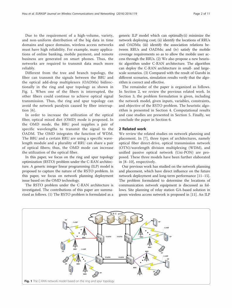
fiber can transmit the signals between the BBU andthe optical add-drop multiplexers (OADMs) bidirec-tionally in the ring and spur topology as shown inFig. 1. When one of the fibers is interrupted, theother fibers could continue to achieve optical signaltransmission. Thus, the ring and spur topology canavoid the network paralysis caused by fiber interrup-tion [6].In order to increase the utilization of the optical
fiber, optical mixed diet (OMD) mode is proposed. Inthe OMD mode, the BBU pool supplies a pair ofspecific wavelengths to transmit the signal to theOADM. The OMD integrates the function of WDM.The BBU and a certain RRU are using a specific wave-length module and a plurality of RRU can share a pairof optical fibers; thus, the OMD mode can increasethe utilization of the optical fiber.In this paper, we focus on the ring and spur topology
optimization (RSTO) problem under the C-RAN architec-ture. A generic integer linear programming (ILP) model isproposed to capture the nature of the RSTO problem. Inthis paper, we focus on network planning deploymentissue based on the OMD technology.The RSTO problem under the C-RAN architecture is
investigated. The contributions of this paper are summa-rized as follows. (1) The RSTO problem is formulated as a
generic ILP model which can optimally:(i) minimize thenetwork deploying cost; (ii) identify the locations of RRUsand OADMs; (iii) identify the association relations be-tween RRUs and OADMs; and (iv) satisfy the mobilecoverage requirements so as to allow the mobile user ac-cess through the RRUs. (2) We also propose a new heuris-tic algorithm under C-RAN architecture. The algorithmcan deploy the C-RAN architecture in small- and large-scale scenarios. (3) Compared with the result of Gurobi indifferent scenarios, simulation results verify that the algo-rithm is correct and effective.The remainder of the paper is organized as follows.
In Section 2, we review the previous related work. InSection 3, the problem formulation is given, includingthe network model, given inputs, variables, constraints,and objective of the RSTO problem. The heuristic algo-rithm is presented in Section 4. Computational resultsand case studies are presented in Section 5. Finally, weconclude the paper in Section 6.
2 Related workWe review the related studies on network planning andplacement. In [7], three types of architectures, namelyoptical fiber direct-drive, optical transmission network(OTN)/wavelength division multiplexing (WDM), andunified passive optical network (Uni-PON) are pro-posed. These three models have been further elaboratedin [8–10], respectively.Our previous work has studied on the network planning
and placement, which have direct influence on the futurenetwork deployment and long-term performance [11–15].The problem formulated to determine the locations ofcommunication network equipment is discussed as fol-lows. Site planning of relay station GA-based solution ingreen wireless access network is proposed in [11]. An ILP
CoMP
CoMP
OADM
OADMOADM
OADM
RRURRU
RRU
RRURRU
RRU
RRU
RRU
TPTP
TP
TP
TP
TP
TPTP
TP
TP
B B U pool
CoMP
CoMP
Fig. 1 The C-RAN network model based on the ring and spur topology
Hou et al. EURASIP Journal on Wireless Communications and Networking (2016) 2016:119 Page 2 of 11
model is formulated to maximize the throughput of anLTE network in [12]. Cascaded splitter placement and lay-out in long-reach PON are discussed in [13]. A dimen-sioning and site-planning optimization framework wasproposed for integrated PON and wireless cooperativenetworks in [14]. An ILP model for the cascaded LRPONtopology and network equipment placement, and networkdimensioning are proposed in [15].Other related works have studied on topology and
placement optimization, such as [16] and [17]. A modelfor combined virtual core network function placementand topology optimization is proposed in [16]. In [17], theauthor presents some optimization problems in WMNsand different heuristic methods such as local search, gen-etic algorithms, and tabu search for solving them near-optimally. Relayed-Based Heterogeneous Wireless AccessNetworks (RHWAN) is envisioned as the promising net-work architecture proposed in [18]. A hybrid wirelessmesh network infrastructure which connects the smartmeters of each consumer with the data aggregation points(DAP) is proposed in [19]. An optimal deployment modelon Universal Data Aggregation Point (UDAP) is proposedin [20].In this research, we choose the ring and spur topology
optimization based on the OMD technology under theC-RAN architecture. The fiber can bidirectionally trans-mit the signal between the BBU and the OADMs; thus,it has high network survivability. Wireless access net-work is demanded to provide higher reliability in the bigdata era. To the best of our knowledge, there are fewstudies on the deployment and optimization for C-RANinfrastructure under the ring and spur topology, whichis just the focus of our research.
3 Network model and problem formulation3.1 Network modelThe C-RAN network model consists of four networkentities: BBU, OADM, RRU, and mobile stations (MSs), asshown Fig. 1. The OADMs and the RRUs are eligible tobe deployed at certain outdoor potential sites (PSs) whereuninterrupted power supply can be provided [5].
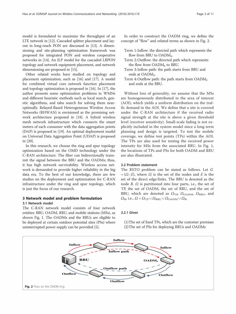
In order to construct the OADM ring, we define theconcept of “flow” and related terms as shown in Fig. 2.
Term 1: Inflow: the directed path which represents theflow from BBU to OADMk.
Term 2:Outflow: the directed path which representsthe flow from OADMk to BBU.
Term 3: Inflow path: the path starts from BBU andends at OADMk.
Term 4:Outflow path: the path starts from OADMk
and ends at the BBU.
Without loss of generality, we assume that the MSsare homogeneously distributed in the area of interest(AOI), which yields a uniform distribution on the traf-fic demand in the AOI. We define that a site is coveredunder the C-RAN architecture if the received radiosignal strength at the site is above a given thresholdlevel (receiver sensitivity). Small-scale fading is not ex-plicitly included in the system model since a long-termplanning and design is targeted. To test the mobilecoverage, we define test points (TPs) within the AOI.The TPs are also used for testing the received powerintensity for MSs from the associated RRU. In Fig. 1,the locations of TPs and PSs for both OADM and RRUare also illustrated.
3.2 Problem statementThe RSTO problem can be stated as follows. Let G= (Ω : E), where Ω is the set of the nodes and E is theset of the direct edge/links. The BBU is denoted as thenode B. Ω is partitioned into four parts, i.e., the set ofTP, the set of OADM, the set of RRU, and the set ofBBU, which are denoted as ΩTP, ΩOADM, ΩRRU, andΩB, i.e., Ω =ΩTP ∪ΩRRU ∪ΩOADM ∪ΩB.
3.2.1 Given
(1)The set of fixed TPs, which are the customer premises(2)The set of PSs for deploying RRUs and OADMs
BBU OADMk
InflowInflow
Outflow
Outflow
Outflow
Inflow
Inflow path
Outflow path
Fig. 2 Flow on the OADM ring
Hou et al. EURASIP Journal on Wireless Communications and Networking (2016) 2016:119 Page 3 of 11
(3)The location of the BBU(4)The cost per unit length of fiber ($/km) Cf,
including fiber purchase and deployment cost.(5)The Manhattan distance between node i and node
j (dij).(6)The cost of RRU (CR) and OADM (CO).(7)The maximal transmit power of a RRU(8)The minimal signal-to-noise-ratio (SNR) requirement
for an MS
3.3 Variable
(1)The PSm is selected to place a RRU if am = 1;otherwise, am = 0.
(2)The PSt is selected to place an OADM if bt = 1;otherwise, bt = 0.
(3)The MS at TPn is associated with the RRU if zmn = 1;otherwise, zmn = 0.
(4)There is a directed link from node i∈ΩB∪ΩOADM
to node j ∈ΩB∪ΩRRU∪ΩOADM if eij = 1;otherwise, eij = 0.
(5)The TPn is covered if qn = 1; otherwise, qn = 0.(6)eij is on the directed flow from the BBU to OADMk
if gkij ¼ 1; otherwise, gkij ¼ 0.(7)eij is on the directed flow from the OADMk to BBU
if hkij ¼ 1; otherwise hkij ¼ 0.
3.4 Constraints
(1)The mobile coverage requirement should besatisfied, i.e., the coverage ratio should be largerthan a predefined value.
(2)The SNR for an MS located at each TP should belarger than a SNR threshold.
(3)Each TP is covered by at least one RRU.(4)The OADM ring consists the BBU and the selected
OADMs.(5)There must be at least a RRU to connect to the
selected OADM.(6)The RRU can cover the MS with CoMP technology.(7)The double-flow control is used to establish the
mathematical model.(8)If the PS is selected to place an OADM on the
OADM ring, there must be an input path andoutput path.
3.5 ObjectiveThe objective is to minimize the infrastructure deploy-ment cost of the whole C-RAN network. Table 1 listsimportant symbols for the problem formulation.
3.6 Problem formulation(RSTO) objective:
Table 1 Definitions of Symbols in the RSTO problem
Symbol Definition
ΩB The set of the BBU
ΩOADM The set of the OADMs
ΩRRU The set of the RRUs
ΩTP The set of the TPs
T The number of OADMs in the network
M The number of RRUs in the network
N The number of TPs in the network
dij The distance between node i and node j
P The maximal transmit power of a RRU
ξ The average normalized thermal noise in AOI
α The path loss exponent
s0 The minimal SNR requirement for each TP
A The location incidence vector, A = (am)1 ×M
B The location incidence vector, B = (bt)1 × T
Q A TP coverage incidence vector, Q = (qn)1 × N
Z RRU-TP association matrix Z = (zmn)M × N
E BBU-OADM-RRU association matrix, E = (eij)(T + 1) × (M + T)
DMAX The maximal distance of OMD-RRU that can be deployed in the network
HK OADMk − BBU flow association matrix HK ¼ hkij
� �1þTð Þ� TþMð Þ
GK BBU −OADMk flow association matrix GK ¼ gkij
� �1þTð Þ� TþMð Þ
Hou et al. EURASIP Journal on Wireless Communications and Networking (2016) 2016:119 Page 4 of 11
Minimize C ¼ CF þ CRRU þ COADM ð1:1Þwhere
CF ¼X
i∈ΩBeij þ eij� �
⋅dij þ CfX
i∈ΩOADMeij⋅dij
þ CfX
i∈ΩOADM
Xj∈ΩRRU
eij⋅dij
ð1:1aÞ
CRRU ¼ CRX
m∈ΩRRUam ð1:1bÞ
COADM ¼ COX
t∈ΩOADMbt ð1:1cÞ
Equation (1.1) is to minimize the total deploymentcost of the C-RAN network, including the cost of fibers,the cost of RRUs, and the cost of OADMs.Subject to:X
m∈ΩRRUzmn ≥1; ∀n∈ΩTP ð1:2Þ
zmn≤an; ∀m∈ΩRRU; ∀n∈ΩTP ð1:3Þeij≤bi; ∀i∈ΩOADM; ∀j∈ΩRRU ð1:4Þ
Constraint (1.2) stipulates that each TP is covered byat least one RRU, and it ensures the CoMP feature ofC-RAN. Constraint (1.3) ensures that the PS is selectedto place a RRU if am = 1. Constraint (1.4) ensures thatthe PS is selected to place an OADM if bi = 1.
Xj∈ΩOADM
eij ¼ 1 ; ∀i∈ΩB ð1:5ÞX
i∈ΩOADMeij ¼ 1 ; ∀j∈ΩB ð1:6Þ
Constraints (1.5) and (1.6) ensure that the BBU can beconnected to the OADM ring. Constraint (1.5) stipulatesthat the BBU has just only one OADM as BBU’s output.Constraint (1.6) stipulates that the BBU has just onlyone OADM as BBU’s input.
Xi∈ΩB∪ΩOADM
eij ¼ aj;∀j∈ΩOADM; i≠j ð1:7Þ
Xj∈ΩB∪ΩOADM
eij ¼ aj ; ∀i∈ΩOADM; i≠j ð1:8Þ
Constraints (1.7) and (1.8) ensure that an OADM canbe connected to the OADM ring. Constraint (1.7) en-sures that if the PS is selected to place an OADM on theOADM ring, then anther OADM serves as an outputterminal in the OADM ring. Constraint (1.8) ensuresthat if the PS is selected to place an OADM on theOADM ring, then anther OADM serves as an input ter-minal in the OADM ring.
Xi∈ΩOADM
eij ¼ aj; ∀j∈ΩRRU ð1:9ÞX
j∈ΩRRUeij≥bi ; ∀i∈ΩOADM ð1:10Þ
Constraint (1.9) ensures that if the PS is selected toplace an OADM on the OADM ring, then at least oneRRU should be connected to the selected OADM, if aj =1. Constraint (1.10) ensures that RRUs can be connectedto the OADM, if bi = 1.
eij⋅dij≤Dmax;∀i∈ΩOADM;∀j∈ΩRRU ð1:11Þ
Constraint (1.11) sets an upper bound on the fiberlength between an OADM and a RRU in C-RAN network.
gkij≤eij;∀i∈ΩB∪ΩOADM; ∀j∈ΩOADM; k ∈ΩOADM; i≠k
ð1:12Þ
hkij≤eij;∀i∈ΩOADM;∀j∈ΩB∪ΩOADM; k∈ΩOADM; j≠k
ð1:13Þ
Constraint (1.12) stipulates that only when eij = 1, eijprobably exists in the inflow path from BBU toOADMk. Constraint (1.13) stipulates that only when eij= 1, eij probably exists in the outflow path from theBBU to OADMk.
gkij≤bk ; ∀i∈ΩB∪ΩOADM; ∀j∈ΩOADM; k∈ΩOADM; i≠k
ð1:14Þ
hkij≤bk ;∀i∈ΩOADM; ∀j∈ΩB∪ΩOADM; k∈ΩOADM; j≠k
ð1:15Þ
Constraints (1.14) and (1.15) ensure only when OADMi
and OADMj exist firstly, then there probably exists thepath between the BBU and OADMk.
Xj∈ΩOADM
gkij ¼ bk ; ∀k ∈ΩOADM ; i∈ΩB ð1:16ÞX
i∈ΩOADMhkij ¼ bk ; ∀k∈ΩOADM; j∈ΩB ð1:17Þ
For all OADMs, constraints (1.16) and (1.17) ensurewhere the inflow path must start from the BBU, and theoutflow path must end at the BBU.
Xi∈ΩB∪ΩOADM
gkik ¼ bk ; ∀k∈ΩOADM ; i≠k ð1:18ÞX
j∈ΩB∪ΩOADMhkkj ¼ bk ;∀k∈ΩOADM ; j≠k ð1:19Þ
Constraints (1.18) and (1.19) stipulate that for OADMk,its inflow path must end at OADMk, and its outflow muststart from OADMk.
Hou et al. EURASIP Journal on Wireless Communications and Networking (2016) 2016:119 Page 5 of 11
Xj∈ΩOADM
Xk ∈ΩOADM
gkij ¼X
k ∈ΩOADMbk ; i∈ΩB
ð1:20ÞX
i∈ΩOADM
Xk ∈ΩOADM
hkij ¼X
k ∈ΩOADMbk ; j∈ΩB
ð1:21ÞConstraints (1.20) and (1.21) ensure that only when
OADMk is selected to place on the OADM ring, thenOADMk has an inflow path and an outflow path.
Xi∈ΩB∪ΩOADM
gkij ¼X
m∈ΩOADMgkjm;∀j; k∈ΩOADM;
i≠ j≠m; i≠ j≠k
ð1:22Þ
Xi∈ΩOADM
hkij ¼X
m∈ΩB∪ΩOADMhkjm; ∀j; k∈ΩOADM;
i≠ j≠m ; i≠ j≠k
ð1:23Þ
Constraint (1.22) stipulates that if OADMj is onthe path from BBU to OADMk, then OADMj has aninput path and an output path. Also, there is an in-flow path that belongs to the path from BBU toOADMj. Constraint (1.23) stipulates that if OADMj
is on the path from BBU to OADMk, then OADMj
has an input path and an output path. Also, there isan outflow path that belongs to the path from BBUto OADMk.
gkij þ hkij≤1;∀i; j; k ∈ΩOADM; i≠ j≠k ð1:24Þ
eij þ eji≤1; ∀i∈ΩB∪ΩOADM; ∀j∈ΩOADM; i≠ j ð1:25Þ
1ξ
Xm∈ΩRRU
zmn � Pdαmn
≥ s0 ; ∀n∈ΩTP ð1:26Þ
qn≥1X
m∈ΩRRU
Pξdα
mn−s0
Xm∈ΩRRU
Pξdα
mn−s0
� �
ð1:27Þ
1−qn≥1X
m∈ΩRRU
Pξdα
mn−s0
s0−X
m∈ΩRRU
Pξdα
mn
� �
ð1:28Þ1N
Xn∈ΩTP
qn≥η� 100% ð1:29Þ
For OADMk, constraint (1.24) stipulates that the samepath cannot exist in the inflow path and outflow path atthe same time. Constraint (1.25) stipulates that the path is
directional, which means only one direction can bechosen. Constraint (1.26) ensures that the TP satisfies theconstraint of the minimum SNR requirement. Constraints(1.27)–(1.29) stipulate the definition of Q.
am∈ 0; 1f g; ∀m∈ΩRRU; bt∈ 0; 1f g; ∀t∈ΩOADM;
qn∈ 0; 1f g; ∀n∈ΩTP
ð1:30Þzmn∈ 0; 1f g; ∀m∈ΩRRU; ∀n∈ΩTP ð1:31Þ
eij∈ 0; 1f g; ∀i∈ΩB∪ΩOADM; ∀j∈ΩOADM∪ΩRRU
ð1:32Þ
gkij∈ 0; 1f g; ∀i∈ΩB∪ΩOADM; ∀j∈ΩOADM; k∈ΩOADM; i≠k
ð1:33Þ
hkij∈ 0; 1f g; ∀i∈ΩOADM; ∀j∈ΩB∪ΩOADM; k∈ΩOADM; j≠k
ð1:34ÞConstraints (1.30)–(1.34) state the each entry A, B, Q,
Z, E, HK, and GK is binary.
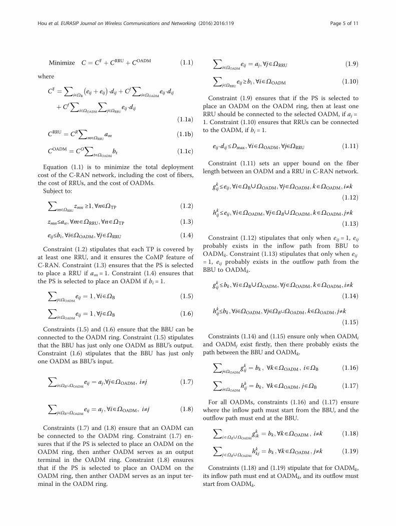
4 Heuristic algorithm4.1 Algorithm descriptionThe problem formulation is given in the previous section,including the network model, given inputs, variables, con-straints, and objective of the RSTO problem. However,with the continuous expansion of network size, solvingthe above RSTO formulation is not an easy task especiallyfor large-scale networks due to the exponential growingnature of ILP. To make the design more scalable for large-size networks, in this section, we propose a new heuristicalgorithm.The design and process of this new heuristic algorithm
is mainly concluding some steps as follows:
(1)Initialization of system parameters.(2)RRU selection. This step achieves the coverage TP
through candidate RRU.(3)OADM selection.(4)Construct the C-RAN architecture based on the ring
and spur topology.(5)C-RAN layout (including the location of selected
RRUs and OADMs, the optical link between RRUsand OADMs, the optical ring of OADMs and BBU,the association between RRUs and OADMs), totaldeployment cost.
Now, we introduce the pseudocode of this the heuris-tic algorithm, and then we give an application based onthis heuristic algorithm.The pseudocode of the heuristic algorithm is outlined
below.
Hou et al. EURASIP Journal on Wireless Communications and Networking (2016) 2016:119 Page 6 of 11
The proposed heuristic is stated in detail as follows:
Step 1 (Lines 1–2): Initialization. Firstly, a plurality ofTPs, potential sites for deploying RRUs, andOADMs are set in an AOI after an actual survey. Atwo-dimensional coordinate graph is established onthe basis of the latitude and longitude of the actualpositions of TPs, and RRU candidates and OADMcandidates are import into this two-dimensionalcoordinate graph based on their actual location ofthe latitude and longitude. The distances between TPsand RRU candidates (i.e., parameter dT − R), RRUcandidates and OADM candidates (i.e., parameter
0 0.1 0.2 0.3 0.4 0.5 0.6 0.7 0.8 0.9 10
0.1
0.2
0.3
0.4
0.5
0.6
0.7
0.8
0.9
1
0 0
1
2
3
4 5
6
7
8 9
0
1
2
3
4 5
6
7
8
9
10
11
12
13
14
15
16
17 18
19
0
1
2
3
4 5
6
7
8 9 10 11
12
13
14 15
16 17
18
19
20 21
22 23
24 25
26
27 28
29 30
31 32
33
BBU
OADMTP
RRU
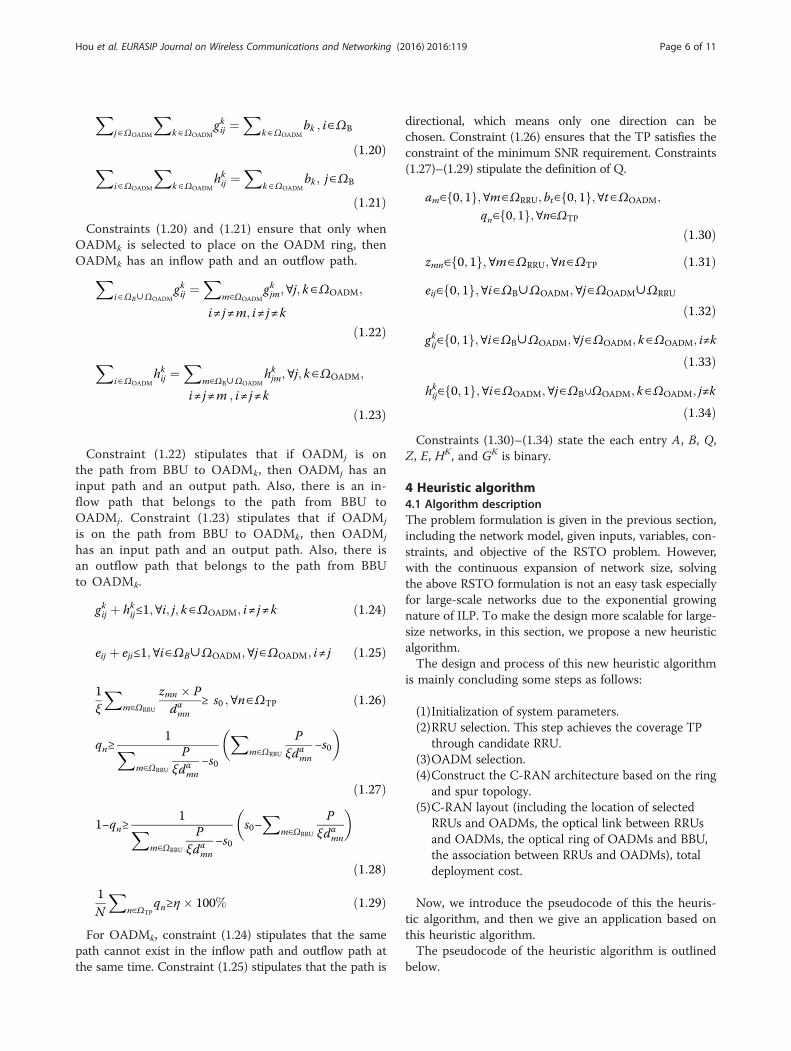
Fig. 3 The layout and setting of scenario 0 beforetopology optimization
0 0.2 0.4 0.6 0.8 10
0.1
0.2
0.3
0.4
0.5
0.6
0.7
0.8
0.9
1
0 0
1
2
3
4 5
6
7
8 9
0
1
2
3
4 5
6
7
8
9
10
11
12
13
14
15
16
17 18
19
0
1
2
3
4 5
6
7
8 9 10 11
12
13
14 15
16 17
18
19
20 21 22 23
24 25
26
27 28
29 30
31 32
33
BBU
OADMTP
RRU
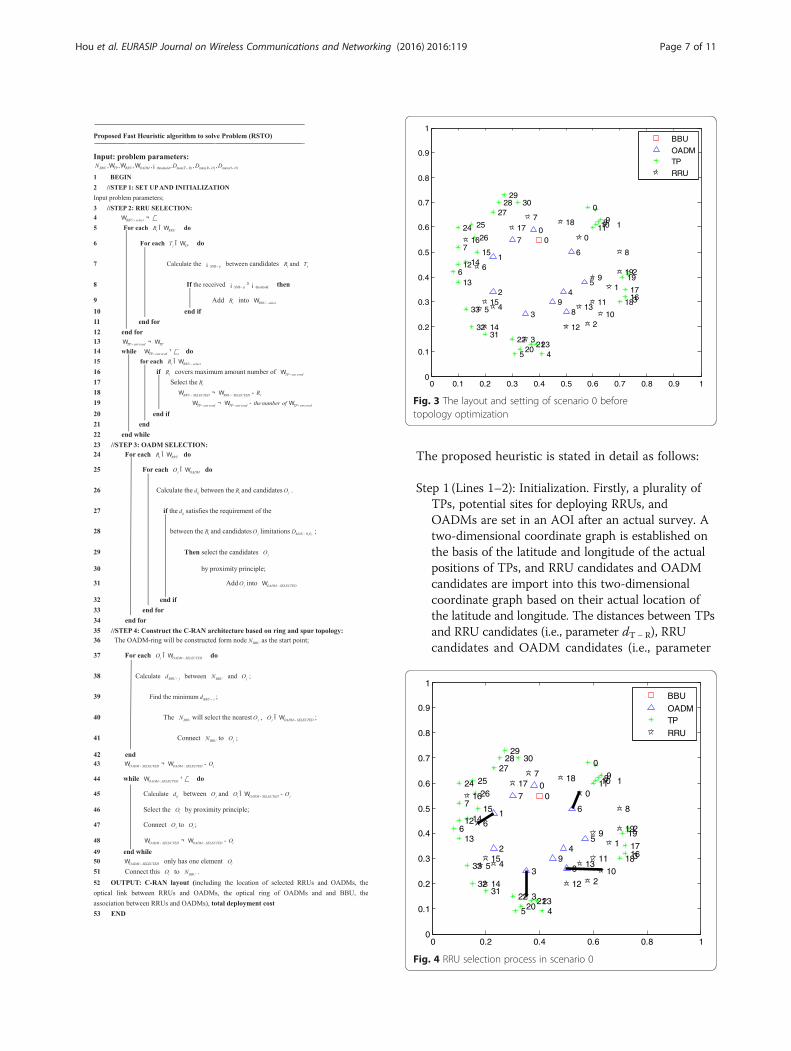
Fig. 4 RRU selection process in scenario 0
Hou et al. EURASIP Journal on Wireless Communications and Networking (2016) 2016:119 Page 7 of 11
dR −O), OADM candidates and OADM candidates(i.e., parameter dO −O) are calculated and stored,respectively. The parameters of NBBU,ΩTP,ΩRRU,ΩOADM, threshold,Dmax(T − R),Dmax(R −O),Dmax(O −O)
are set according to the requirement of actualdeployment scenarios.
Step 2 (Lines 3–22): RRU selection. The goal of thisstep is to make each TP covered by one candidateRRU. First, we calculate the SNR between the TPsand candidates RRUs. If the received SNR at a TPform a candidate RRU that satisfies the minimumSNR threshold, then we select the RRU whichcovers the maximum amount of the TPs, then addthis RRU into ΩRRU − selected.We will delete thisalready selected RRU and these TPs which arecovered by selected RRU. The TPs will select theRRU in turn according to the calculated TPnumbers covered by the candidate RRU indescending order The candidates can be selecteduntil all TPs are covered by the candidate RRU.
Step 3 (Lines 23–34): OADM selection. The goal of thisstep is to set up the optical links between thecandidate OADM and all the selected RRUs at step2. We calculate the distances between the selectedRRUs and candidate OADMs. If the distancesatisfies the requirement of the selected RRU andcandidate OADM limitations (i.e., parameterDmax(R −O)), we select the candidate OADM by aproximity principle. Then, we will add this OADMinto ΩOADM − selected. If each selected RRU couldselect an OADM which satisfies the requirement ofthe distance limitations, then these OADMs will beadded into ΩOADM − selected. The loop will end until
all the selected RRU at step 2 could connect to anOADM. The optical links between the selectedRRU at step 2 and OADM can be set up.
Step 4 (Lines 35–51): Construct the C-RAN architecturebased on the ring and spur topology. The goal of thisstep is to construct the OADM ring. The ring willbe constructed from the BBU as the start point.Firstly, we calculate the distance (i.e., parameterdBBU −O) between the BBU and the selectedOADMs (i.e., parameter ΩOADM − selected). Secondly,we find the minimum dBBU−Oj for all Oj and connectthe BBU to the corresponding Oj, then remove thisOj in ΩOADM − selected. Thirdly, we calculate thedistance (dOj−Oi ) between Oj and Oi (Oi∈ΩOADM −
selected −Oj), then we also find the minimumdistance and connect Oj to Oi. The loop will enduntil the ΩOADM − selected has only one element Oi.Finally, we connect this Oi to BBU, and the OADMring can be constructed.
Finally, in lines 52–53, the heuristic outputs the layoutsolution (including the location of the selected RRUs andOADMs, the optical link between RRUs and OADMs, theoptical ring of OADMs and BBU, the association betweenRRUs and OADMs) and total deployment cost.
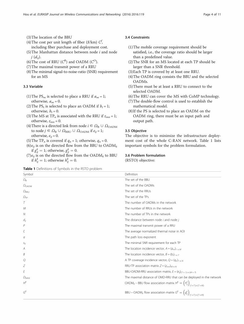
4.2 An example for the proposed fast heuristic algorithmIn this section, we use a small-scale scenario, denotedas scenario 0, as an example to illustrate the procedureof the proposed algorithm. The parameter setting ofscenario 0 is as follows: the set of TPs denotes PTP , thecandidate RRUs denote PRRU, and the candidateOADMs denote POADM (see Fig. 3).We defined a generic cost unit (gcu) [21] to simplify
the evaluation of deployment costs in all the casestudies.
0 0.2 0.4 0.6 0.8 10
0.1
0.2
0.3
0.4
0.5
0.6
0.7
0.8
0.9
1
0 0
1
2
3
4 5
6
7
8 9
0
1
2
3
4 5
6
7
8
9
10
11
12
13
14
15
16
17 18
19
0
1
2
3
4 5
6
7
8 9 10 11
12
13
14 15
16 17
18
19
20 21 22 23
24 25
26
27 28
29 30
31 32
33
BBU
OADMTP
RRU
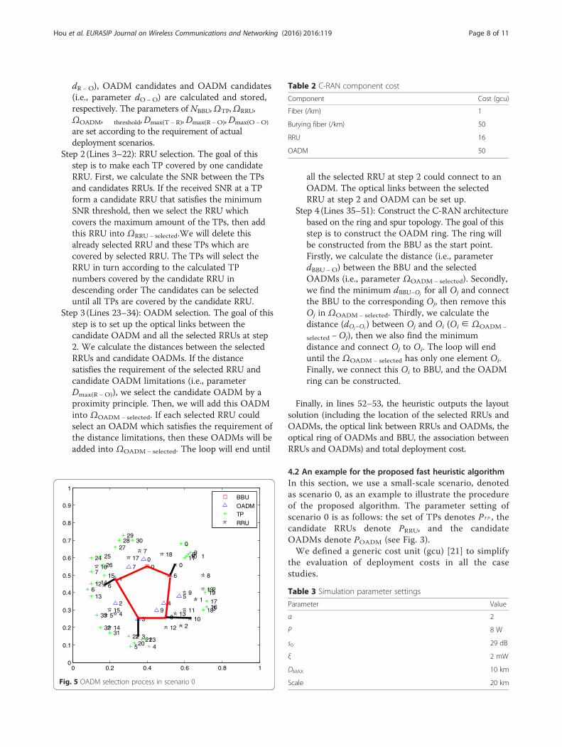
Fig. 5 OADM selection process in scenario 0
Table 2 C-RAN component cost
Component Cost (gcu)
Fiber (/km) 1
Burying fiber (/km) 50
RRU 16
OADM 50
Table 3 Simulation parameter settings
Parameter Value
α 2
P 8 W
s0 29 dB
ξ 2 mW
DMAX 10 km
Scale 20 km
Hou et al. EURASIP Journal on Wireless Communications and Networking (2016) 2016:119 Page 8 of 11
Step 1: Initialization.Step 2: Achieve all of the TPs that can be covered by
the candidate RRUs. In Fig. 3, the set of the candidateRRUs denotes PRRU = {PRRU0, PRRU1, PRRU2,⋯, PRRU19}.The set of the candidate OADMs denotes POADM
¼ POADM0; POADM1;⋯; POADM9f g . The set of TPs denotesPTP ¼ PTP0; PTP1;PTP2;⋯; PTP34f g. All of the TPs can becovered by the four RRUs, PRRU10; PRRU0; PRRU3; PRRU6. Inspecific, 17 TPs can be covered by PRRU10; 6 TPs can becovered by PRRU0; 6 TPs can be covered by PRRU3; and 6TPs can be covered by PRRU6.Step 3: For all the selected RRUs, the optical link be-
tween the candidate OADMs and the selected RRUs willbe connected at this step. Instead of using a proximityprinciple in selecting the candidate OADMs, we alsoconclude the distance between the RRUs and OADMs.In Fig. 4, there are four OADMs which can be con-nected to the RRUs, which are denoted as POADM1; POADM3; POADM6; POADM8: In specific, the PRRU6 can be connectedto POADM1 , the PRRU3 can be connected to POADM3 , thePRRU0 can be connected to POADM6, and the PRRU10 can beconnected to POADM8.Step 4: Achieve the C-RAN architecture based on ring
and spur. In this step, the ring topology will start formBBU, then the BBU will select the nearest OADM. We
marked this OADM as OADM-s(1). If the OADM-s(1)connects to the RRUs, then the OAMD satisfies theOADM ring. In Fig. 5, the BBU connects to POADM6, thenPOADM6 connects to POADM8, POADM8 connects to POADM3,POADM3 connects to POADM1, and POADM1 connects to BBU.So, the ring and spur topology can be constructed at thisstep.Finally, output the optical link between RRUs and
OADMs, the optical link between OADM and BBU, theassociation between RRUs and OADMs (see Fig. 5).Step 5: Compute the total deployment cost, computing
time in this ring and spur topology.In scenario 0, the total deployment cost is 1824.43 gcu.
The topology running time is 1.308 s. The layout and totaldeployment cost results of the ring and spur topologyunder C-RAN is the same as the result obtained with Gur-obi which will be introduced later in next section.
5 Numerical analysis5.1 Parameter settingsWe implement the optimization model of the previoussection and solve the RSTO problem using GurobiOptimizer [22], which is a state-of-the-art ILP solver.
0 0.1 0.2 0.3 0.4 0.5 0.6 0.7 0.8 0.9 10
0.1
0.2
0.3
0.4
0.5
0.6
0.7
0.8
0.9
1
0 1 2
3 4 5 6 7
8 9
BBU
PS for OADMTP
PS for RRU
1 2
34
56
78
9
10
1
23
4 5
x
y
0 0.1 0.2 0.3 0.4 0.5 0.6 0.7 0.8 0.9 10
0.1
0.2
0.3
0.4
0.5
0.6
0.7
0.8
0.9
1ba
0 1 2
3 4 5 6 7
8 9
BBU
PS for OADMTP
PS for RRU
1 2
34
56
78
9
10
1
23
4 5
x
y
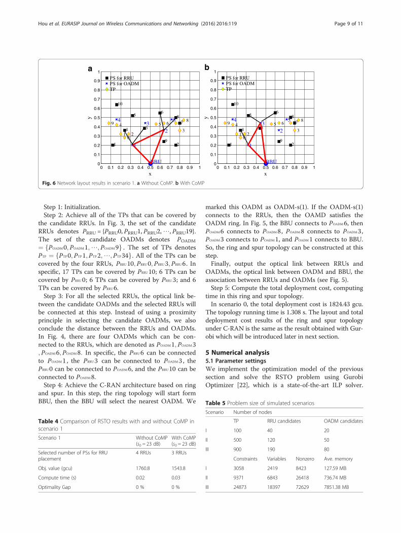
Fig. 6 Network layout results in scenario 1. a Without CoMP. b With CoMP
Table 4 Comparison of RSTO results with and without CoMP inscenario 1
Scenario 1 Without CoMP(s0 = 23 dB)
With CoMP(s0 = 23 dB)
Selected number of PSs for RRUplacement
4 RRUs 3 RRUs
Obj. value (gcu) 1760.8 1543.8
Compute time (s) 0.02 0.03
Optimality Gap 0 % 0 %
Table 5 Problem size of simulated scenarios
Scenario Number of nodes
TP RRU candidates OADM candidates
I 100 40 20
II 500 120 50
III 900 190 80
Constraints Variables Nonzero Ave. memory
I 3058 2419 8423 127.59 MB
II 9371 6843 26418 736.74 MB
III 24873 18397 72629 7851.38 MB
Hou et al. EURASIP Journal on Wireless Communications and Networking (2016) 2016:119 Page 9 of 11
Gurobi is designed to exploit modern multi-core pro-cessors and the performance is proved to be superior toCPLEX [23]. Without loss of generality, the Manhattandistance of two nodes is used to represent the corre-sponding edge length of the fiber deployment route,and all the fiber segment links have the same weighteddeployment costs.Tables 2 and 3 show the component cost of C-RAN
and experimental parameters, respectively. We still usethe generic cost unit (gcu) [21] to simplify the evaluationof deployment costs in the case studies.In scenario 0, we have validated the solvability of (RSTO)
formulation and the effectiveness of our proposed heuris-tic. To further investigate the effect of CoMP in the C-RAN planning strategy, we compare the resulting networklayout configuration with and without CoMP technologyin scenario 1 as shown in Fig. 6. We can observe the differ-ence between Figs. 6a, b. The number of the selected RRUsin Fig. 6a is more than that in Fig. 6b. Table 4 shows thecorresponding computing result of network optimal layoutin scenario 1. It compares the objective value with andwithout CoMP. Obviously, the total cost of the networkwill be increased without CoMP. In other words, the in-corporation of CoMP technology can lead to a significantcost reduction for C-RAN.
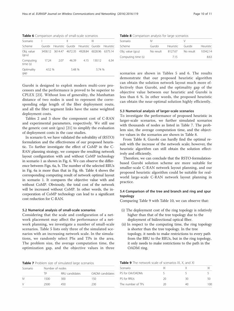
5.2 Numerical analysis of small-scale scenariosConsidering that the scale and configuration of a net-work placement may affect the performance of a net-work planning, we investigate a number of small-scalescenarios. Table 5 lists only three of the simulated sce-narios with an increasing network scale. In the simula-tions, we randomly select PSs and TPs in the area.The problem size, the average computation time, theoptimization gap, and the objective values in three
scenarios are shown in Tables 5 and 6. The resultsdemonstrate that our proposed heuristic algorithmcan obtain the solution network layout much more ef-fectively than Gurobi, and the optimality gap of theobjective value between our heuristic and Gurobi isless than 6 %. In other words, the proposed heuristiccan obtain the near-optimal solution highly efficiently.
5.3 Numerical analysis of larger-scale scenariosTo investigate the performance of proposed heuristic inlarger-scale scenarios, we further simulated scenarioswith thousands of nodes as listed in Table 7. The prob-lem size, the average computation time, and the object-ive values in the scenarios are shown in Table 8.From Table 8, Gurobi can hardly find the optimal re-
sult with the increase of the network scale; however, theheuristic algorithm can still obtain the solution effect-ively and efficiently.Therefore, we can conclude that the RSTO-formulation-
based Gurobi solution scheme are more suitable forsmaller-scale C-RAN network layout planning, and ourproposed heuristic algorithm could be suitable for real-world large-scale C-RAN network layout planning inpractice.
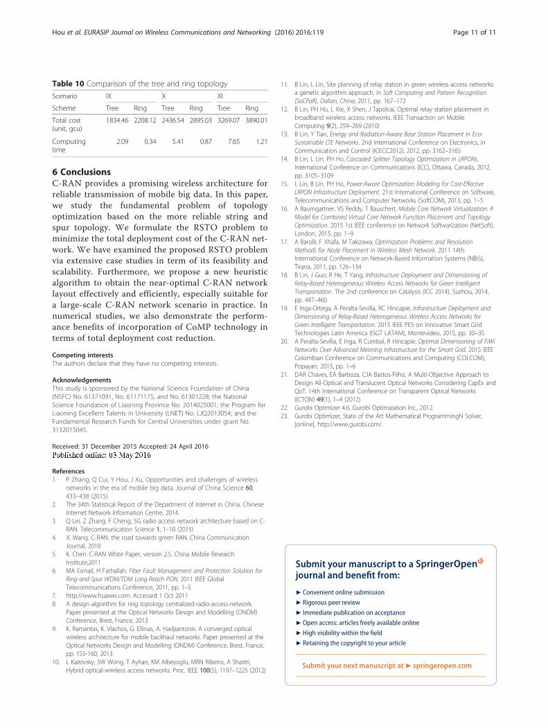
5.4 Comparison of the tree and branch and ring and spurtopologyComparing Table 9 with Table 10, we can observe that:
(i) The deployment cost of the ring topology is relativelyhigher than that of the tree topology due to thedeployment of bidirectional optical fiber.
(ii) In respect to the computing time, the ring topologyis shorter than the tree topology. In the treetopology, it needs to make restrictions to every pathfrom the BBU to the RRUs, but in the ring topology,it only needs to make restrictions to the path in theOADM ring.
Table 6 Comparison analysis of small-scale scenarios
Scenario I II III
Scheme Gurobi Heuristic Gurobi Heuristic Gurobi Heuristic
Obj. value(gcu)
3458.12 3614.47 4672.35 4928.84 6028.96 6375.14
Computingtime (s)
17.24 2.07 46.39 4.15 130.12 6.34
Optimalitygap
4.52 % 5.48 % 5.74 %
Table 7 Problem size of simulated large scenarios
Scenario Number of nodes
TP RRU candidates OADM candidates
IV 1500 300 150
V 2500 450 230
Table 8 Comparison analysis for large scenarios
Scenario IV V
Scheme Gurobi Heuristic Gurobi Heuristic
Obj. value (gcu) No result 8127.67 No result 10342.14
Computing time (s) 7.15 8.63
Table 9 The network scale of scenarios IX, X, and XI
Scenario IX X XI
PS for OA/OADMs 5 5 5
PS for RRUs 20 30 50
The number of TPs 20 40 100
Hou et al. EURASIP Journal on Wireless Communications and Networking (2016) 2016:119 Page 10 of 11
6 ConclusionsC-RAN provides a promising wireless architecture forreliable transmission of mobile big data. In this paper,we study the fundamental problem of topologyoptimization based on the more reliable string andspur topology. We formulate the RSTO problem tominimize the total deployment cost of the C-RAN net-work. We have examined the proposed RSTO problemvia extensive case studies in term of its feasibility andscalability. Furthermore, we propose a new heuristicalgorithm to obtain the near-optimal C-RAN networklayout effectively and efficiently, especially suitable fora large-scale C-RAN network scenario in practice. Innumerical studies, we also demonstrate the perform-ance benefits of incorporation of CoMP technology interms of total deployment cost reduction.
Competing interestsThe authors declare that they have no competing interests.
AcknowledgementsThis study is sponsored by the National Science Foundation of China(NSFC) No. 61371091, No. 61171175, and No. 61301228; the NationalScience Foundation of Liaoning Province No. 2014025001; the Program forLiaoning Excellent Talents in University (LNET) No. LJQ2013054; and theFundamental Research Funds for Central Universities under grant No.3132015045.
Received: 31 December 2015 Accepted: 24 April 2016
References1. P Zhang, Q Cui, Y Hou, J Xu, Opportunities and challenges of wireless
networks in the era of mobile big data. Journal of China Science 60,433–438 (2015)
2. The 34th Statistical Report of the Department of Internet in China. ChineseInternet Network Information Centre, 2014.
3. Q Lei, Z Zhang, F Cheng, 5G radio access network architecture based on C-RAN. Telecommunication Science 1, 1–10 (2015)
4. X. Wang. C-RAN: the road towards green RAN. China CommunicationJournal, 2010
5. K. Chen. C-RAN White Paper, version 2.5. China Mobile ResearchInstitute,2011
6. MA Esmail, H Fathallah, Fiber Fault Management and Protection Solution forRing-and-Spur WDM/TDM Long-Reach PON. 2011 IEEE GlobalTelecommunications Conference, 2011, pp. 1–5
7. http://www.huawei.com. Accessed 1 Oct 20118. A design algorithm for ring topology centralized-radio-access-network.
Paper presented at the Optical Networks Design and Modelling (ONDM)Conference, Brest, France, 2013
9. K. Ramantas, K. Vlachos, G. Ellinas, A. Hadjiantonis. A converged opticalwireless architecture for mobile backhaul networks. Paper presented at theOptical Networks Design and Modelling (ONDM) Conference, Brest, France,pp. 155-160, 2013
10. L Kazovsky, SW Wong, T Ayhan, KM Albeyoglu, MRN Ribeiro, A Shastri,Hybrid optical-wireless access networks. Proc. IEEE 100(5), 1197–1225 (2012)
11. B Lin, L Lin, Site planning of relay station in green wireless access networks:a genetic algorithm approach, in Soft Computing and Pattern Recognition(SoCPaR), Dalian, China, 2011, pp. 167–172
12. B Lin, PH Ho, L Xie, X Shen, J Tapolcai, Optimal relay station placement inbroadband wireless access networks. IEEE Transaction on MobileComputing 9(2), 259–269 (2010)
13. B Lin, Y Tian, Energy and Radiation-Aware Base Station Placement in Eco-Sustainable LTE Networks. 2nd International Conference on Electronics, inCommunication and Control (ICECC2012), 2012, pp. 3162–3165
14. B Lin, L Lin, PH Ho, Cascaded Splitter Topology Optimization in LRPONs.International Conference on Communications (ICC), Ottawa, Canada, 2012,pp. 3105–3109
15. L Lin, B Lin, PH Ho, Power-Aware Optimization Modeling for Cost-EffectiveLRPON Infrastructure Deployment. 21st International Conference on Software,Telecommunications and Computer Networks (SoftCOM), 2013, pp. 1–5
16. A Baumgartner, VS Reddy, T Bauschert, Mobile Core Network Virtualization: AModel for Combined Virtual Core Network Function Placement and TopologyOptimization. 2015 1st IEEE conference on Network Softwarization (NetSoft),London, 2015, pp. 1–9
17. A Barolli, F Xhafa, M Takizawa, Optimization Problems and ResolutionMethods for Node Placement in Wireless Mesh Network. 2011 14thInternational Conference on Network-Based Information Systems (NBiS),Tirana, 2011, pp. 126–134
18. B Lin, J Guo, R He, T Yang, Infrastructure Deployment and Dimensioning ofRelay-Based Heterogeneous Wireless Access Networks for Green IntelligentTransportation. The 2nd conference on Catalysis (ICC 2014), Suzhou, 2014,pp. 447–460
19. E Inga-Ortega, A Peralta-Sevilla, RC Hincapie, Infrastructure Deployment andDimensioning of Relay-Based Heterogeneous Wireless Access Networks forGreen Intelligent Transportation. 2015 IEEE PES on Innovative Smart GridTechnologies Latin America (ISGT LATAM), Montevideo, 2015, pp. 30–35
20. A Peralta-Sevilla, E Inga, R Cumbal, R Hincapie, Optimal Dimensioning of FiWiNetworks Over Advanced Metering Infrastructure for the Smart Grid. 2015 IEEEColombian Conference on Communications and Computing (COLCOM),Popayan, 2015, pp. 1–6
21. DAR Chaves, EA Barboza, CJA Bastos-Filho, A Multi-Objective Approach toDesign All-Optical and Translucent Optical Networks Considering CapEx andQoT. 14th International Conference on Transparent Optical Networks(ICTON) 49(1), 1–4 (2012)
22. Gurobi Optimizer 4.6, Gurobi Optimization Inc., 2012.23. Gurobi Optimizer, State of the Art Mathematical ProgrammingN Solver,
[online], http://www.gurobi.com/.
Submit your manuscript to a journal and benefi t from:
7 Convenient online submission
7 Rigorous peer review
7 Immediate publication on acceptance
7 Open access: articles freely available online
7 High visibility within the fi eld
7 Retaining the copyright to your article
Submit your next manuscript at 7 springeropen.com
Table 10 Comparison of the tree and ring topology
Scenario IX X XI
Scheme Tree Ring Tree Ring Tree Ring
Total cost(unit, gcu)
1834.46 2208.12 2436.54 2895.03 3269.07 3890.01
Computingtime
2.09 0.34 5.41 0.87 7.65 1.21
Hou et al. EURASIP Journal on Wireless Communications and Networking (2016) 2016:119 Page 11 of 11