Embed Size (px)
Citation preview

Infrared Techniques for Practical Defect Identification in BondedJoints in Liquefied Natural Gas Carriers
R.C. Tighe1 & J.M. Dulieu-Barton1& S. Quinn1
Received: 27 January 2017 /Accepted: 30 July 2017 /Published online: 28 August 2017# The Author(s) 2017. This article is an open access publication
Abstract A robust and reliable method for the identificationof defects in adhesively bonded joints used in the membranecontainment system used to store liquefied natural gas duringtransport on board ships is required. The adhesively bondedinterface of the membrane system may contain low volumedefects known as kissing defects, which are extremely diffi-cult to detect using portable inspection techniques. A novelmethodology for detecting such defects is described in thepaper. To demonstrate the approach simulated kissing defectswere produced in a controlled fashion in a representative sec-ondary membrane bond using silicon grease contamination.The defects were detected using an active thermographic ap-proach known as pulsed phase thermography (PPT) whichdetects subsurface defects by monitoring the effect they haveon the propagation of heat through a component. Due to thelow volume of kissing defects, they generally have minimaleffect on the heat propagation, so the detection was madepossible by application of a small load generated by applica-tion of a vacuum. The vacuum can be set-up using a reusablechamber and a standard vacuum pump and therefore is porta-ble and can be applied on-site and in a shipyard duringconstruction.
Keywords Pulse phase thermography .GTTMkIII . Vacuumloading . Liquefied natural gas carriers
Introduction
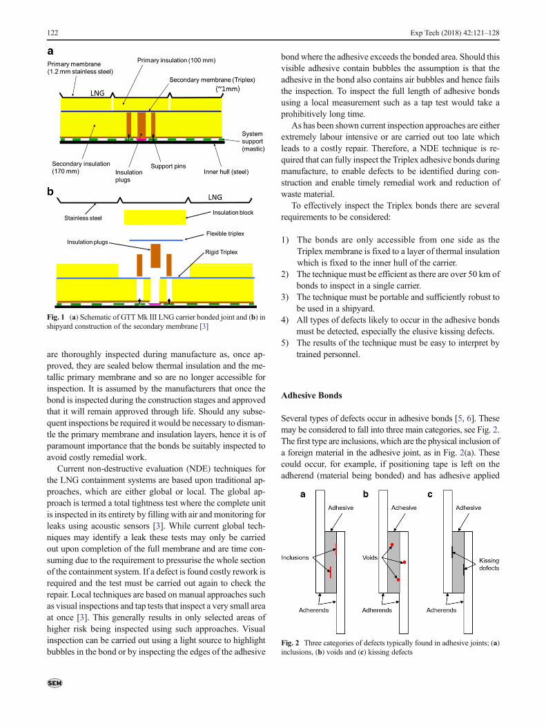
Natural gas provides 47% of electricity in the UK [1] andaccounts for 25% of global energy. Of this global use 10% issupplied as liquefied natural gas (LNG) [2]. With the decreaseof local sources and a need to diversify supply chains a largerpercentage of this gas is set to come via the sea, aboard largecarriers as liquefied natural gas (LNG). Of the 410 LNG car-riers active in 2015, 76% have membrane style containmentsystems [2]. The membrane containment system consists of ametallic primary membrane, responsible for containing theLNG and a secondary membrane. The GTT Mk III systemis a membrane style LNG containment system where the sec-ondary membrane is formed using Triplex™. An alternativesecondary membrane material of Invar with welded joints isalso used, however, due to the welded joints; this is not thesubject of the present paper. Triplex is a composite materialcomposed of a 0.6 mm layer of aluminium with a layer ofglass fibre cloth on either side [3, 4]. There are two types ofTriplex: rigid, which contains a resin with a high Young’smodulus or, flexible, which incorporates a resin with a lowerYoung’s modulus. The Mk III containment system is formedin prefabricated sections which are then installed in the carrier.The prefabricated sections include the rigid Triplex. The flex-ible Triplex is then used to bond two adjoining pieces of rigidTriplex together to form a continuous secondary containmentsystem, as shown in Fig. 1(a) and (b). The purpose of thesecondary membrane is to protect the ship’s hull from expo-sure to LNG if the primary membrane were to fail. To ensurethe integrity of the secondary membrane it is necessary toinspect the quality of the adhesive bond and detect any defectsthat may have been introduced during manufacture. The totallength of adhesive bond found in current Mk III carriers isover 50 km, and with an expected increase in carrier size thisis set to more than double [3]. It is paramount that these bonds
* R.C. [email protected]
1 Faculty of Engineering and the Environment, University ofSouthampton, Southampton SO17 1BJ, UK
Exp Tech (2018) 42:121–128DOI 10.1007/s40799-017-0200-7
are thoroughly inspected during manufacture as, once ap-proved, they are sealed below thermal insulation and the me-tallic primary membrane and so are no longer accessible forinspection. It is assumed by the manufacturers that once thebond is inspected during the construction stages and approvedthat it will remain approved through life. Should any subse-quent inspections be required it would be necessary to disman-tle the primary membrane and insulation layers, hence it is ofparamount importance that the bonds be suitably inspected toavoid costly remedial work.
Current non-destructive evaluation (NDE) techniques forthe LNG containment systems are based upon traditional ap-proaches, which are either global or local. The global ap-proach is termed a total tightness test where the complete unitis inspected in its entirety by filling with air andmonitoring forleaks using acoustic sensors [3]. While current global tech-niques may identify a leak these tests may only be carriedout upon completion of the full membrane and are time con-suming due to the requirement to pressurise the whole sectionof the containment system. If a defect is found costly rework isrequired and the test must be carried out again to check therepair. Local techniques are based on manual approaches suchas visual inspections and tap tests that inspect a very small areaat once [3]. This generally results in only selected areas ofhigher risk being inspected using such approaches. Visualinspection can be carried out using a light source to highlightbubbles in the bond or by inspecting the edges of the adhesive
bond where the adhesive exceeds the bonded area. Should thisvisible adhesive contain bubbles the assumption is that theadhesive in the bond also contains air bubbles and hence failsthe inspection. To inspect the full length of adhesive bondsusing a local measurement such as a tap test would take aprohibitively long time.
As has been shown current inspection approaches are eitherextremely labour intensive or are carried out too late whichleads to a costly repair. Therefore, a NDE technique is re-quired that can fully inspect the Triplex adhesive bonds duringmanufacture, to enable defects to be identified during con-struction and enable timely remedial work and reduction ofwaste material.
To effectively inspect the Triplex bonds there are severalrequirements to be considered:
1) The bonds are only accessible from one side as theTriplex membrane is fixed to a layer of thermal insulationwhich is fixed to the inner hull of the carrier.
2) The technique must be efficient as there are over 50 km ofbonds to inspect in a single carrier.
3) The technique must be portable and sufficiently robust tobe used in a shipyard.
4) All types of defects likely to occur in the adhesive bondsmust be detected, especially the elusive kissing defects.
5) The results of the technique must be easy to interpret bytrained personnel.
Adhesive Bonds
Several types of defects occur in adhesive bonds [5, 6]. Thesemay be considered to fall into three main categories, see Fig. 2.The first type are inclusions, which are the physical inclusion ofa foreign material in the adhesive joint, as in Fig. 2(a). Thesecould occur, for example, if positioning tape is left on theadherend (material being bonded) and has adhesive applied
Fig. 1 (a) Schematic of GTTMk III LNG carrier bonded joint and (b) inshipyard construction of the secondary membrane [3]
Fig. 2 Three categories of defects typically found in adhesive joints; (a)inclusions, (b) voids and (c) kissing defects
122 Exp Tech (2018) 42:121–128
over it. The second type are voids which are caused by theinclusion of air in the joint, see Fig. 2(b). These could occurbetween the adhesive and adherend during joint assembly or befound in the adhesive itself if air is introduced, e.g. duringmixing of a two part adhesive. The final category of defectare kissing defects. Kissing defects are the result of improperadhesion between the adhesive and the adherend, as shown inFig. 2(c), where the adhesive/adherend interface is not as strongas expected for that joint configuration [6]. A decreased level ofadhesion leads to reduced joint strength and is a significantthreat to structural integrity. As all components of the jointare present and in contact, kissing defects are the most difficulttype of defect to detect using NDE techniques. The presentpaper focusses on the detection of kissing defects as these arethe most challenging defect to detect as they provide very littlematerial property contrast to aid NDE techniques in theirdetection.
Voids and inclusions are of known origin and are thereforerelatively easy to recreate in the laboratory, however, the exactcause of kissing defects is unknown. Possible causes arethought to be contamination, abnormality in the adhesivechemistry or curing process, moisture ingress, residual stress-es, or a combination of these factors [7, 8]. Several studieshave focused on the recreation of kissing defects in the labo-ratory [9]. Most have categorised kissing defects into twotypes, dry contact and liquid layer [10]. In a dry contact rec-reation, adhesive is applied to one adherend and cured. Theother adherend is put in position and held in place by com-pressive loading. In the case of a dry contact bond no actualadhesion occurs between the adhesive and adherend. A liquidlayer defect is achieved by the introduction of a thin layer of acontaminant such as grease at the adhesive/adherend interface.The thickness of the contaminant is much thinner than thethickness of the adhesive layer but has a detrimental effecton the strength of the joint as the level of adhesion is reducedby up to 80% of the original bond shear strength over thecontaminated area [11].
NDE of Adhesive Bonds
Several standards exist for the NDE of adhesive bonds incomposite materials, these include: ASTM E1495/ E1495M(acousto-ultrasonics), ASTM E2582–7 (flash thermography)andASTMSTP1184 (acoustic emission). However, it is wide-ly accepted that conventional NDE techniques are not current-ly able to identify all types of defects that occur in adhesivebonds, specifically kissing bonds [12]. A brief outline of someof the techniques investigated to detect defects in adhesivebonds beyond those of the standards is given below.
Acousto-ultrasonics (AU) is a combination of acousticemission and ultrasound; an ultrasonic source is used to ‘load’the sample and the ability of a component to transfer strainenergy introduced by the small stresses caused by the
ultrasonic excitation is measured. A correlation was foundbetween AU measurements and the strength of lap shearbonded composites [13]. However, AU does not allow defectsto be visualised, but rather gives a measure of their effect onthe overall strength of the bond, and so does not aid in atargeted remediation methodology.
Awide range of literature exists focussing on the develop-ment of advanced ultrasound (UT) techniques for the inspec-tion of adhesive bonds [14]. Standard C-scan UT is currentlyused for NDE of bonded joints in the aerospace industry dur-ing manufacture [15]. However, the time consuming point bypoint nature and water coupling of this approach make it dif-ficult to implement on site. Application of Lamb waves foridentification of debonds in adhesive bonds is the subject ofseveral investigations, as they may be used without directaccess to the joints, e.g. [16, 17]. Lambwaves (or plate waves)may be used for inspection of materials where their thicknessis a few wavelengths of the applied wave. The waves propa-gate parallel to the surface of the material throughout thethickness of the material creating localised regions of tensionand compression enabling detection of defects where the elas-tic material properties differ from the surrounding bulk prop-erties [18].
Shearography has been used for identification of defects inadhesive joints in materials including aluminium and CFRPusing flat bottom hole defects in the bond lines [19].Shearography is able to identify a range of defects includinginserts and adhesive starvation in adhesive bonds in rubber,CFRP and ceramics [20]. The main drawback found withshearography was that the interpretation of the fringe patternresults needs to be carried out by trained personnel. There hasbeen some work towards automation of the procedure [21]which is still ongoing.
Asmentioned previously, acoustic emission [22] is current-ly used to detect bonding defects in the Mk III carrier once thewhole tank has been constructed. Acoustic emission has alsobeen used to assess bonding integrity for a rocket motor case[23]. Finite element analysis (FEA) was incorporated with theacoustic emission data to provide threshold readings to relatean acoustic emission signal rate to a threshold level that cor-relates to a strain distribution over the bond.
Thermographic NDE has the ability to inspect large areasin short periods of time with easily interpretable results [9].Thermography requires the creation of a temperature gradientbetween defect and non-defect regions to enable defect detec-tion [24]. In the literature thermographic techniques have beentested for specific applications of bonded joints. A compositetruck box with adhesively bonded joints was tested usingpulsed thermography (PT) to identify mechanical damage inthe composite panels and disbonds in the adhesive joints [25].The bond defect found using PT was then identified as astarved bond where insufficient force was applied to fullyadhere the bond; this may therefore be considered as a void
Exp Tech (2018) 42:121–128 123
or delamination of the bond line. As this type of defect has avolume filled with air it cannot be considered a kissing defect,and hence can be identified. Bonded joints between CFRPreinforcement patches and concrete have been assessed usingPT to identify a range of defect types including unbonding,where no adhesive is present, delaminations, and debonding[26]. Variations in the pulse duration and the distance from theheat lamp to the sample were studied and minimum strengthand pulse durations were suggested to study such compositerepairs. Omar et al. [27] used thermography to study bondintegrity of plastic welded joints. Results show this methodwas able to identify areas of delamination in the bonded re-gion, and even though the defects were classed as kissingdefects [27] it appeared that the defects have a volume, andhence are not strictly speaking kissing defects as defined in thepresent paper.
In the literature thermographic approaches have shownpromise for the inspection of adhesively bonded joints.Thermography is able to detect defects where there is a vari-ation between defect and surrounding material thermal prop-erties [28]. Kissing defects do not provide such a contrast,therefore to be able to detect kissing defects using thermogra-phy it is necessary to enhance the thermal contrast between thedefect and the surrounding material.
Aim
The aim of the current research is to explore the potential ofusing active thermographic methods, specifically pulsedphase thermography (PPT) [28], to develop a reliable methodof identifying kissing defects in the adhesive bonds found inthe secondary membrane of GTT Mk III carriers. The goalbeing to define the technology required to make a robust andportable device for NDE of adhesive bonds in a shipyardduring the construction stage. The work builds on that pre-sented in [29] for specific application on the GTT Mk IIIcarriers.
Pulsed Phase Thermography
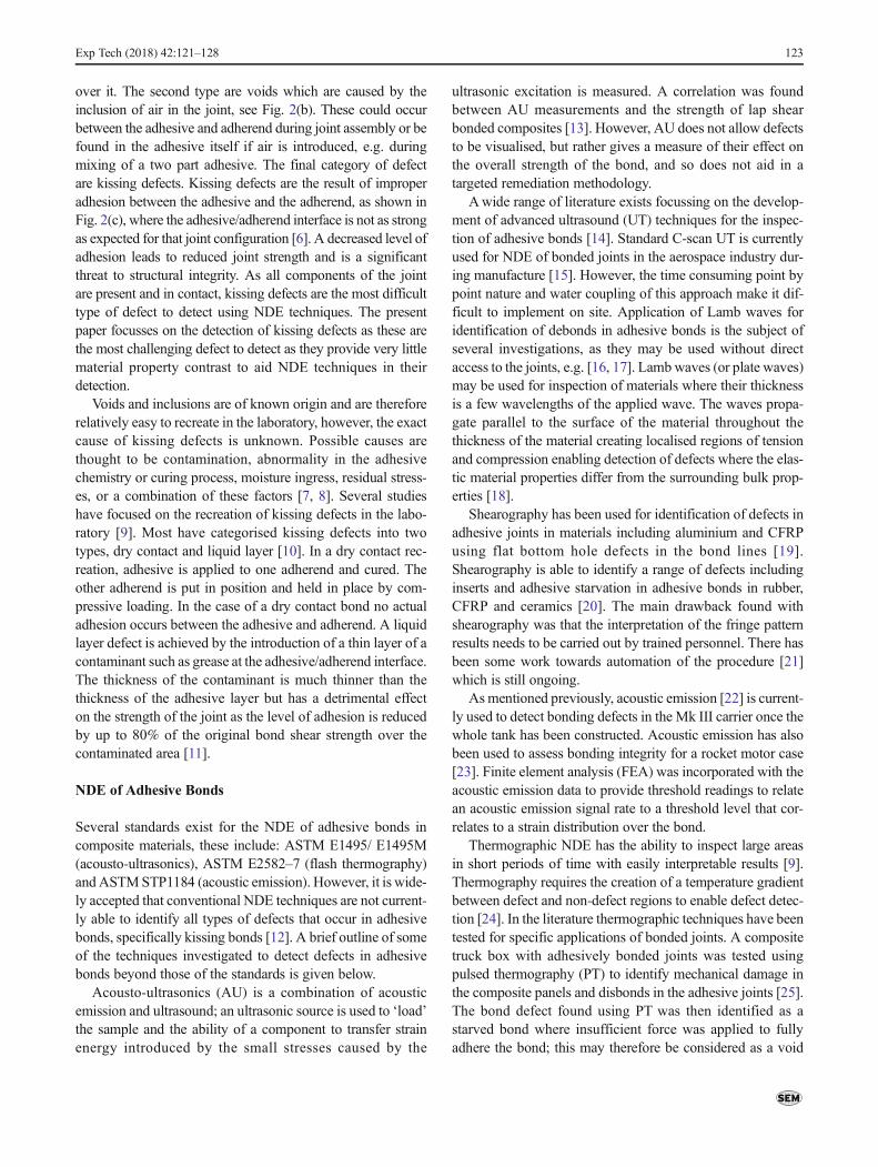
A schematic of the experimental set up for PPT is given in Fig. 3.As only single sided access is available for the Triplex joints theinspection must be carried out using reflection mode PPTwherethe heat source and infrared (IR) detector are on the same side ofthe bond. When dealing with such thin materials the impact ofusing reflection mode compared to through transmission mode(with the detector and heating on opposite sides of the compo-nent) on the identification of defects is negligible. PPT involvesthe application of a pulse of heat to the surface of the material.Once the surface is heated an IR detector is used to monitor thesurface temperature evolution as the heat front propagatesthrough the thickness of the material. Where the material is
laterally uniform across the area of inspection the heat front willpropagate uniformly and the surface temperature will remainuniform. However, where there is a region of differing thermalproperties, such as if there was a void below the surface, the heatpropagation will be affected. The variation in heat front propa-gation local to such a defect will result in non-uniformity in thesurface temperature over the defect. From this non-uniformity thelocation and extent of a defectmay be inferred.While for shallowdefects, that create a strong thermal contrast, the defects can bevisible directly in the recorded thermal data it is generally neces-sary to post process the thermal decay data into phase data usinga fast Fourier transform. The application of the FFT involvesprocessing the data from each pixel through time into phase data[30].This enables external effects such as surface reflections andnon-uniform heating to be reduced and deeper or less stronglycontrasting defects to be revealed.
All thermography based techniques rely on there being acontrast in material and defect thermal properties. Kissingdefects however, offer little or no thermal contrast, thus wouldnot normally be identified using this approach. A novel aspectof this work is to apply a small non-destructive load to openkissing defects to enhance their thermal contrast and enabledefect detection. The Triplex bond lends itself to this approachas there is a stiffness mismatch between the flexible and rigidTriplex, i.e. between the two adherends of the joint and theflexible Triplex of the accessible adherend. When the flexibleTriplex is loaded it will more easily deform than its rigidcounterpart, enabling a kissing defect to be opened.Furthermore, due to the low level of loading required to elas-tically deform the flexible Triplex material it may be possibleto use a vacuum to open existing defects to enable their de-tection. The final concept would be to have a PPT inspectionsystem contained within a vacuum hood, making a portablepractical tool as shown in Fig. 4, labelled vacuum position 1.However, due to the cooled nature of the photon detector used,initial tests have applied the load to the rear of the samplewhile inspection is carried out on the opposite surface, asshown in Fig. 4, labelled vacuum position 2. The initial setuprequired two sided access to the bond which would limit theapplication of the technique in its current form, however thisenabled a proof of concept to be investigated. It would be
Fig. 3 Schematic of pulse phase thermography experimental set-up
124 Exp Tech (2018) 42:121–128

anticipated that should the design be taken into industry thetype of detector would be changed to be a microbolometerwhich would enable the PPT setup to be incorporated intothe vacuum design, creating a tool requiring only single sidedaccess. A microbolometer can be more easily used in a vacu-um as it does not require cooling, unlike the photon detectorcurrently used and would simply need power and data cablesto exit the vacuum. Although the microbolometer and heatpulse would generate heat it is anticipated this would quicklydissipate, particularly when moving the device between in-spection sites where the vacuum would be lost. Some initialwork has been carried out to examine the performance ofmicrobolometers in vacuums. This has shown that a carefulselection of the microbolometer type and lens is necessary.Further, at higher vacuum level the electronics can be affected;however for this application it is not necessary to apply such ahigh level vacuum.
Methodology
Initial trials were conducted to demonstrate the ability of theexperimental procedure for the identification of features with-in a Triplex bond with inspection through the Triplex material.This was carried out on a rigid Triplex – flexible Triplex (RT-FT) bond with a polytetrafluoroethylene (PTFE) insert in thebond line. The PTFE insert was not meant to simulate a defectbut rather to provide a known feature within the bond foridentification to establish the suitable thermographic experi-mental parameters, including heat stimulus required, camerarecording frequency and duration of data collection.
A second test piece representative of the bonds found inLNG carriers was produced to demonstrate the concept ofkissing defect detection with the application of a vacuum load.Although the initial RT-FT joint thermally simulates the LNGcarrier joint, it does not mechanically simulate the joint.Within the LNG carrier the Triplex is adhered to the rigidTriplex and thick insulation blocks, thus a stiffness mismatchis present between the two adherends of the bond. The stiff-ness mismatch has been recreated for laboratory testing usinga CFRP plate as the second adherend. The sample consisted ofthe flexible Triplex material adhered to a CFRP plate with
layup [0 90]s, as shown in Fig. 4. In the laboratory trials thebond is inspected from the CFRP side, although in practiceinspection will occur through the flexible Triplex, as in thefirst round of trials. The adhesive used for the simulated jointwas an epoxy based adhesive, creating a total bond thicknessof 1.4 mm. A 20 mm square patch of silicon grease contam-ination was introduced to the CFRP side of the bond with totalbond dimensions of 250 × 150 mm. The silicon grease createda liquid layer style simulated kissing defect. The vacuum wasapplied, as shown in Fig. 4 as vacuum position 1, by using asmall portable aluminium chamber, which was attached to thesample using sealant tape. A standard laboratory vacuumpump was used to apply the vacuum; the levels of vacuumpressure achieved are defined relative to the pump perfor-mance, i.e. 100% is maximum vacuum applied by the pumpwhich creates a pressure of approximately 0.15 bar and 0% isatmospheric pressure, approximately 1 bar.
A FLIR 5500SC photon detector was used to collect thethermal data, which comprises a 320 × 256 array of InSbdetectors which are sensitive in the wavelength range of 3–5 μm. The detector has a noise equivalent thermal difference(NETD) of 20 mK. Data was collected using the full frame ofdetectors with a frame rate of 100 Hz and a 10 s recordingtime. The data was collected and processed in the PPT phasedata using the detector manufacturer’s propriety softwareAltair and AltairLI. Settings were established during the initialtrials on the RT-FT PTFE sample. The heat source was a
Fig. 4 Vacuum loading optionson CFRP-Triplex bond with sim-ulated kissing defect
Fig. 5 PPT phase data identifying PTFE insert in Triplex bond throughinspecting through rigid Triplex
Exp Tech (2018) 42:121–128 125
1000 J Bowens Gemini 1000 Pro photographic flash lamp.The flash was positioned 200 mm from the sample to provideapproximately uniform heating across the observed region.The detector was positioned 270 mm from the sample to pro-vide a suitable observation window over the defect site. Thedetector and flash were manually triggered and it was ensuredthat the single pulse from the flash was captured within therecording. As the duration of the pulse was 2.1 ms and detec-tor frame rate is 100 Hz therefore, despite manual triggering,the flash is assumed to only occupy one frame of the record-ing. The pressure of the vacuum pump was varied between0% and 100% in 20% increments and the PPT inspectionrepeated at each vacuum level.
Results
The PTFE is clearly identified in the RT-FT bond, as shown inthe PPT phase data in Fig. 5. This initial test confirmed thePPT setup and experimental procedure selected was suitablefor identification of defects with inspection through theTriplex. Using this defined procedure the second joint config-uration containing the stiffness mismatch between the FT and
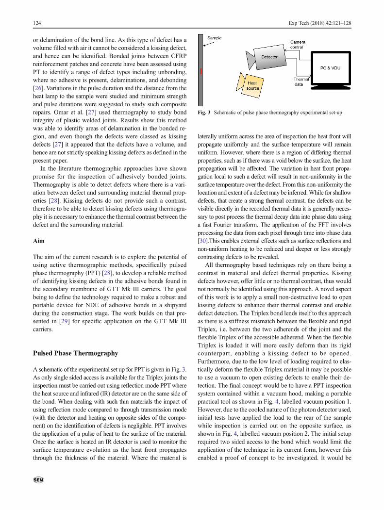
the CFRP was then inspected with the application of vacuumloading for kissing defect detection. Figure 6(a) and (b) showthe PPT phase results of the defect region with no load appliedand full (100%) vacuum loading. The lighter circular ringvisible in the edges of the images is due to the presence ofthe aluminium vacuum chamber attached to the rear of thesample. It is clear that without the addition of load the silicongrease contamination is not visible in the phase data, as isexpected for a kissing defect. When the vacuum is then ap-plied the defect becomes easily identifiable in the centre of theimage in Fig. 6(b). This is emphasised in the profile data takenhorizontally across the centre of the defect position, as shownin Fig. 6(a), for the fully loaded and unloaded conditions. Theprofile plot, in Fig. 7(a), also demonstrates that the regionsaway from the defect, i.e. the well bonded regions, are unaf-fected by the application of the vacuum, hence the defect isnot propagated by the loading and the technique is non-de-structive. It should be noted that an unloaded image was takenafter the full vacuum was applied and the profile returned tothat obtained prior to loading, demonstrating that permanentdeformation had not occurred in the flexible Triplex by thevacuum loading. The joints were also inspected several times,each time giving consistent results further ensuring that the
Fig. 6 PPT phase data for theCFRP/Triplex bonded sample (a)unloaded and (b) full vacuum ap-plied to the rear of the sample
Fig. 7 (a) phase contrast profiles taken across the defect region under vacuum loading conditions of 100% vacuum and 0% vacuum and (b) the meanphase contrast between defect and non-defect regions taken across the width of the defect related to partial vacuum percentage applied
126 Exp Tech (2018) 42:121–128
defect was not propagated during the vacuum loading. Fig. 7(b)shows the mean phase contrast between the defective and non-defective regions for each vacuum partial pressure applied. Thedefect becomes identifiable in the mean phase contrast data atjust 60% of vacuum pressure, thereby highlighting the low levelof load required to generate such results. The level of loadingrequired to open the kissing defect is dependent on the stiffnessof the material and the size and geometry of the defect.Therefore, should a maximum tolerable defect be determinedto be smaller than that tested in the present paper, it would benecessary to ensure sufficient load was applied to reveal such adefect. Definition of such a threshold size is beyond the scope ofthe current work.
Recently [31], a thermographic technique known asthermoelastic stress analysis (TSA) has been applied on site.TSA requires loading, usually in a test machine in a laboratoryenvironment. In [31] the natural frequency of the system isused to provide the cyclic load, This approach would alsohave the benefit of opening the defect to make it more detect-able. However, the prospect of exciting the LNG carrier tankat its natural frequency, even locally, presents a major chal-lenge and hence TSAwas deemed not be a relevant approach,but is an interesting area for further research.
Conclusion
Triplex joints representative of those found in the GTTMk IIILNG carrier were studied using PPT. Kissing defects, whichwere of specific interest, were simulated using silicon grease.To provide sufficient stiffness to simulate a real Triplex bondthe flexible Triplex was adhered to a CFRP panel. A vacuumload was applied to the flexible Triplex, exploiting the stiff-ness mismatch between the adherends, to facilitate the open-ing of the defect. PPT was carried out on the CFRP surface.Sufficient load was applied to the sample to begin to open the20 mm defect at just 60% of full vacuum. Even under theapplication of full vacuum loading the profile data demon-strated that the defect did not grow and after removal of theload the defect closed, thus no plastic deformation was caused.To allow the Triplex joints on the carriers to be inspected itwould be necessary to position the PPT setup within the vac-uum chamber using an uncooled bolometer style detector toprovide the single sided access required. It is necessary toassess the performance of bolometers in a vacuum environ-ment and initial unpublished work in a vacuum chamber hasshown that it is possible to collect data under such circum-stances with minimal impact on the bolometer function. It istherefore considered that a promising new portable approachfor the detection of defects on site has been demonstrated withthe potential to be applied in a wide range of productionenvironments.
Acknowledgements This work was supported by the Lloyds RegisterEducational Trust and the Engineering and Physical Sciences ResearchCouncil. The authors particularly acknowledge the contribution and in-sight of David Howarth, formerly of Lloyd’s Register, Materials Weldingand NDE Marine Technical Policy Group, London, UK.
Open Access This article is distributed under the terms of the CreativeCommons At t r ibut ion 4 .0 In te rna t ional License (h t tp : / /creativecommons.org/licenses/by/4.0/), which permits unrestricted use,distribution, and reproduction in any medium, provided you give appro-priate credit to the original author(s) and the source, provide a link to theCreative Commons license, and indicate if changes were made.
References
1. Energy UK (2014) Electricity Generation http://www.energy-uk.org.uk/energy-industry/electricity-generation.html. Accessed 16Jan 2017
2. International Gas Union (2016) World LNG Report – 2016 Editionhttp://www.igu.org/publications. Accessed 27 Jan 2017
3. Howarth, D. (2006) Adhesive bonding in LNG ship construction.Lloyd’s Register internal report
4. Central commission for the navigation of the rhine/ Oil companiesinternational marine forum (2010) International safety guide forinland navigation tank-barges and terminals, 1st Edn. Chapter 33,pp 505–518
5. Mattox DM (2010) Handbook of physical vapor deposition (PVD)processing, 2nd Edition. Oxford:William Andrew Applied SciencePublishers. p. 54–56
6. Brockmann W, Geiss PL, Klingen J, Schroder B (2009) Adhesivebonding: Adhesives, applications and processes. Wiley-Vch, Germany
7. Adams RD, Cawley P (1988) A review of defect types and nonde-structive testing techniques for composites and bonded joints. NDTInt 21(4):208–222
8. Marty PN, Desai N, Andersson J (2004) NDT of kissing bond inaeronautical structures. In: 16th world conference on NDT, Montreal
9. Roach D, Rackow K, Duvall R (2010) Innovative use of adhesiveinterface characteristics to nondestructively quantify the strength ofbonded joints. In: Proceedings of the 10th European conference onnon-destructive testing. Moscow
10. Yan D, Drinkwater BW, Neild SA (2009) Measurement of the ul-trasonic nonlinearity of kissing bonds in adhesive joints. NDT&EInt 42:459–466
11. Brotherhood CJ, Drinkwater BW, Guild FJ (2002) The effect ofcompressive loading on the ultrasonic detectability of kissing bondsin adhesive joints. J Nondestruct Eval 21(3):95–104
12. Karbhari VM (2013) Non-destructive evaluation (NDE) of polymermatrix composites - techniques and applications. WoodheadPublishing, Composite Science and Engineering Series
13. Karhnak SJ, Duke JC (1994) Predicting performance of adhesivelybonded joints on acousto-ultrasonic evaluation. In: compositebonding ASTM STP 1227. Philadelphia
14. Ehrhart B, Valeske B, Muller CD, Bockenheimer C (2010)Methods for the quality assessment of adhesive bonded CFRPstructures - a resume. We.5.B.2. 2nd international symposium onNDT in aerospace 2010, Hamburg
15. Huke P, Focke O, Falldorf C, von Kopylow C, Bergmann RB(2010) Contactless defect detection using optical methods for nondestructive testing. In 2nd international symposium on NDT inaerospace 2010. Hamburg
16. Cuc A, Giurgiutiu V (2004) Disbond detection in adhesively-bonded structures using piezoelectric wafer active sensors. SPIE11th Annual Symposium on Smart Structures and Materials and
Exp Tech (2018) 42:121–128 127
9th Annual International Symposium on NDE for HealthMonitoring and Diagnostics, March 2004, USA
17. Heller K, Jacobs LJ, Qu J (2000) Characterization of adhesive bondproperties using lamb waves. NDT&E International 33(8):555–563
18. Su Z, Ye L, Lu Y (2006) Guided lamb waves for identification ofdamage in composite structures: a review. J Sound Vib 295(3–5):753–780
19. Hung MYY, Chen YS, Ng SP (2007) Review and comparison ofshearography and pulsed thermography for adhesive bond evalua-tion. Opt Eng 46(5):051007
20. Hung YY, Chen YS, Ng SP, Liu L, Huang YH, Luk BL, Ip RWL,Wu CML, Chung PS (2009) Review and comparison ofshearography and active thermography for nondestructive evalua-tion. Mater Sci Eng R 64(5–6):73–112
21. Hung YY, Ho HP (2005) An optical measurement technique andapplications. Mater Sci Eng: R 49(3):61–87
22. Schliekelmann RJ (1975) Non-destructive testing of bonded joints,recent developments in testing systems. Non-Destr Test 8:100–110
23. Rhee S-H, Hwang T-K (2009) Use of acoustic emission to identifythe bonding status of a rocket motor case. In proceedings of ICCM17. Edinburgh
24. Pickering SG, Chatterjee K, Almond DP, Tuli S (2013) LED opticalexcitation for the long pulse and lock-in thermographic techniques.NDT&E Int 58:72–77
25. Schroeder JA, Ahmed T, Chaudhry B, Shepard S (2002) Non-destructive testing of structural composites and adhesivelybonded composite joints: pulsed thermography. Compos PartA 33:1511–1517
26. Tashan J, Al-Mahadi R (2014) Bond defect detection using PPTIRT in concrete structures strengthened with different CFRP sys-tems. Compos Struct 111:13–19
27. Omar M, Hassan M, Donohue K, Saito K, Alloo R (2006) Infraredthermography for inspecting the adhesion integrity of plasticwelded joints. NDT&E Int 39:1–7
28. Maldague X, Marinetti S (1996) Pulse phase infrared thermogra-phy. J Appl Phys 79(5):2694–2698
29. Tighe RC, Dulieu-Barton JM, Quinn S (2016) Identification ofkissing bonds using infrared thermography. Int J Adhes Adhes64:168–178
30. Maldague X (2001) Theory and practice of infrared technology fornondestructive testing. In: Chang K (ed) Wiley series in microwaveand optical engineering. John Wiley & Sons, Inc, Chichester
31. Tighe RC, Howell GP, Tyler JP, Lormor S, Dulieu-Barton JM(2016) Stress based non-destructive evaluation using thermograph-ic approaches: from laboratory trials to on-site assessment. NDT&EInt 84:76–88
128 Exp Tech (2018) 42:121–128


![PDE-Based Model for Weld Defect Detection on Digital ...€¦ · Shafeek . et al. [12], [13] calculated the area, perimeter, width and height as defect information for defect identification](https://img.pdfslide.us/doc/110x75/5f6554652789c246c94787ee/pde-based-model-for-weld-defect-detection-on-digital-shafeek-et-al-12.jpg)