Embed Size (px)
Citation preview
Infrared imaging of hand vein patterns for biometricpurposes
L. Wang, G. Leedham and S.-Y. Cho
Abstract: A novel non-invasive imaging technique to image the vein patterns in various parts ofthe hand for biometric purposes is evaluated. Two imaging methods are investigated: far-infrared(FIR) thermography and near-infrared (NIR) imaging. Experiments involving data acquisition fromvarious parts of the hand, including the back of the hand, palm and wrist, were carried out usingboth imaging techniques. Analysis of the data collected shows that FIR thermography is less suc-cessful at capturing veins in the palm and wrist. FIR thermography can capture the large veins inthe back of the hand, but it is sensitive to ambient temperature and humidity conditions as well ashuman body temperature. NIR imaging produces good quality images when capturing veins in theback of the hand, palm and wrist. NIR imaging is also more tolerant to changes in the environmentand body condition but faces the problem of pattern corruption because of visible skin featuresbeing mistaken for veins. This corruption is not present in FIR imaging. An initial biometricsystem is investigated to test both FIR and NIR images for biometric purposes. The resultsshow all the subjects were correctly identified, which indicates vein pattern biometrics with infra-red imaging is a potentially useful biometric.
1 Introduction
Biometrics is the science of identifying a person using theirphysiological or behavioural features [1]. Recently, veinpattern biometrics has attracted increasing interest fromboth research communities [2–6] and industries [7]. A veinpattern is the physical structure of the vast network ofblood vessels underneath a person’s skin. Anatomically,aside from surgical intervention, the shape of vascular pat-terns in the same part of the body is distinct for each person[8], and it is very stable over a long period of time, as aperson’s pattern of blood vessels is believed to be ‘hard-wired’ into the body at birth, and remains relatively unaf-fected by ageing, except for predictable growth, as withfingerprints. In addition, as the blood vessels are hiddenunderneath the skin and are invisible to the human eye,vein patterns are much harder for intruders to copy as com-pared to other biometric features. The properties of unique-ness, stability and strong immunity to forgery of the veinpattern make it a potentially good biometric that offerssecure and reliable features for person identity verification.However, as the vein patterns formed by superficial blood
vessels lie underneath the skin surface, the invisibility ofveins to any traditional visual inspection system makes suc-cessful image acquisition of the vein patterns a technicalchallenge. As the quality of the images perform a key rolein all the subsequent processing stages of the vein patternbiometric systems, the image acquisition is critical for thesystem. In many medical practices, X-ray and ultrasonicscanning are used to obtain vascular images. Althoughthese methods can produce high quality images of blood
# The Institution of Engineering and Technology 2007
doi:10.1049/iet-cvi:20070009
Paper first received 15th February and in revised form 5th October 2007
The authors are with the Forensics and Security Lab, School of ComputerEngineering, Nanyang Technological University, Singapore 639798
E-mail: [email protected]
IET Comput. Vis., 2007, 1, (3–4), pp. 113–122
vessels, they are an invasive technique (in the case ofX-rays) as they require injection of contrast agents intothe blood vessels. In addition, excessive doses of X-rayradiation is dangerous. Ultrasonic imaging is less dangerousbut requires the application of a gel to the surface of the skinand the images take several seconds to acquire. Such con-straints are not acceptable for general purpose biometricapplications in the real-world. Obtaining the vein patternimages in a non-invasive manner is the key challenge in avein pattern biometric system. Infrared imaging is capableof capturing the superficial vein patterns inside the humanbody. It provides a no-contact data acquisition methodand requires no injection of any agents into the bloodvessels. Therefore it is potentially a suitable non-invasivemethod to acquire vein pattern images. This paper investi-gates the application of infrared imaging technologies toimage veins in the hand and investigates the various proces-sing and feature extraction stages necessary to determinethe differences between vein patterns.In the entire electromagnetic spectrum, Infrared refers to
a specific region with wavelength typically spanning from0.75 to 1000 mm. This region is commonly furtherdivided into four sub-bands: 1. ‘near-infrared’ (NIR)(0.7522 mm); 2. ‘middle infrared’ (226 mm); 3. ‘far-infrared’ (FIR) (6214 mm); 4. ‘extreme infrared’(1421000 mm). Imaging objects within these four differentregions involves quite different physical mechanisms,which requires special imaging devices, and results inimages with significantly different properties. This researchfocuses on vein imaging using two sub-bands of the infraredspectrum: FIR and NIR. The study is restricted to theseinfrared regions as they are more suitable to captureimages of human bodies, which is elaborated in Sections3.1.1 and 3.2.1 where the principles of the two imagingtechniques were studied in depth.The paper is organised as follows: Section 2 gives an
overview of the current state of the art in vein pattern bio-metrics and their imaging technologies. Section 3
113
investigates the application of FIR and NIR imaging tech-nologies to capture vein patterns in various parts of hands.Their mechanisms and image quality are studied in depth.Following this, in Section 4, the paper describes a databasebuilt as part of the study. To verify the potential of the infra-red vein pattern images for biometric identification, aninitial system is proposed and implemented in Section5. The experimental results are reported in Section6. Finally, Section 7 gives some concluding remarks.
2 Related work
Recently, several institutes and companies have carried outresearch into vein pattern biometric technology. Most of theresearch concentrates on the vein patterns in the face or inthe hand.For the vein pattern in the face, the image of the face is
captured using a thermal camera that records the tempera-ture information of the face, and hence is often referred toas a face thermogram [8]. From a face thermogram, thereare numerous features that can be selected for classification.The most important ones are the thermal curves producedby the main facial arteries. There are many thermal curveswith different shapes that can be observed in a face. Eachof these curves is called an ‘elemental shape’. Person identi-fication has been attempted by measuring the difference ofmany independent sets of these elemental shapes.Compared to face thermograms, acquiring vein patterns
in the hand is considered less intrusive and easier to useby many people. In 1991, a system that scanned the backof a clenched fist to determine hand vein structure for ver-ifying user identity was first reported by MacGregor andWelford [9]. Cambridge Consultants Ltd, in collaborationwith the British Technology Group, also studied the handvein pattern concept with the aim of developing a commer-cial system which they called veincheck, and it was first pre-sented at a seminar in September 1993 [10]. Although thisproduct did not achieve much commercial success, theconcept of using hand vein patterns as a biometricmeasure attracted an increasing amount of research interest.A research team from the Australian Institute of Securityand Applied Technology [3] and a Korean research teamboth used active infrared imaging [4] techniques toacquire the vein patterns in the back of the hand, althoughFujitsu Laboratories has investigated the vein patterns inthe palm side of the hand [7].Although various vein pattern biometric systems have
been developed, there is no published research addressingthe issue of vein pattern acquisition, and there is a lack ofanalysis of the factors affecting the quality of the veinpattern images. The research contribution of this paper isan investigation of the various methods of vein patternimage acquisition using infrared imaging, and the necessaryprocessing to extract features for pattern classification.
3 Infrared imaging of hand vein patterns
3.1 FIR imaging
Almost all black body objects emit radiation when they areheated. The FIR imaging technology forms an image pas-sively using the infrared radiation emitted by the human body.
3.1.1 Principle of imaging: All objects radiate acontinuous spectrum of frequencies. The total emissivepower v is described by the Stefan–Boltzmann law givenin (1), where 1 is the emissivity of the object ands ¼ 5.6703 � 1028 watt/m2 K4 is Stefan’s constant and T
114
is the temperature in Kelvin. The relationship between thewavelength lmax and black body temperature T isformulated by Wien’s displacement law based on Planck’senergy distribution law as given in (2)
w ¼ 1 � s � T 4 (1)
lmax ¼ 2:9 � 10�3=T (2)
Typically, a human body emits infrared radiation withwavelength in the range of 3–14 mm. These infraredwaves radiate into the atmosphere and are attenuatedaccording to the infrared transmittance spectrum of theatmosphere, and at the ranges of 3–5 and 8–14 mm [11],the radiant emittance of infrared spectrum possesses thehighest transmittance rate. Therefore by using a thermalcamera with detector sensitivity in the range of either 3–5or 8–14 mm, an image showing the heat distribution ofthe human body can be generated.Medical researchers have found that human superficial
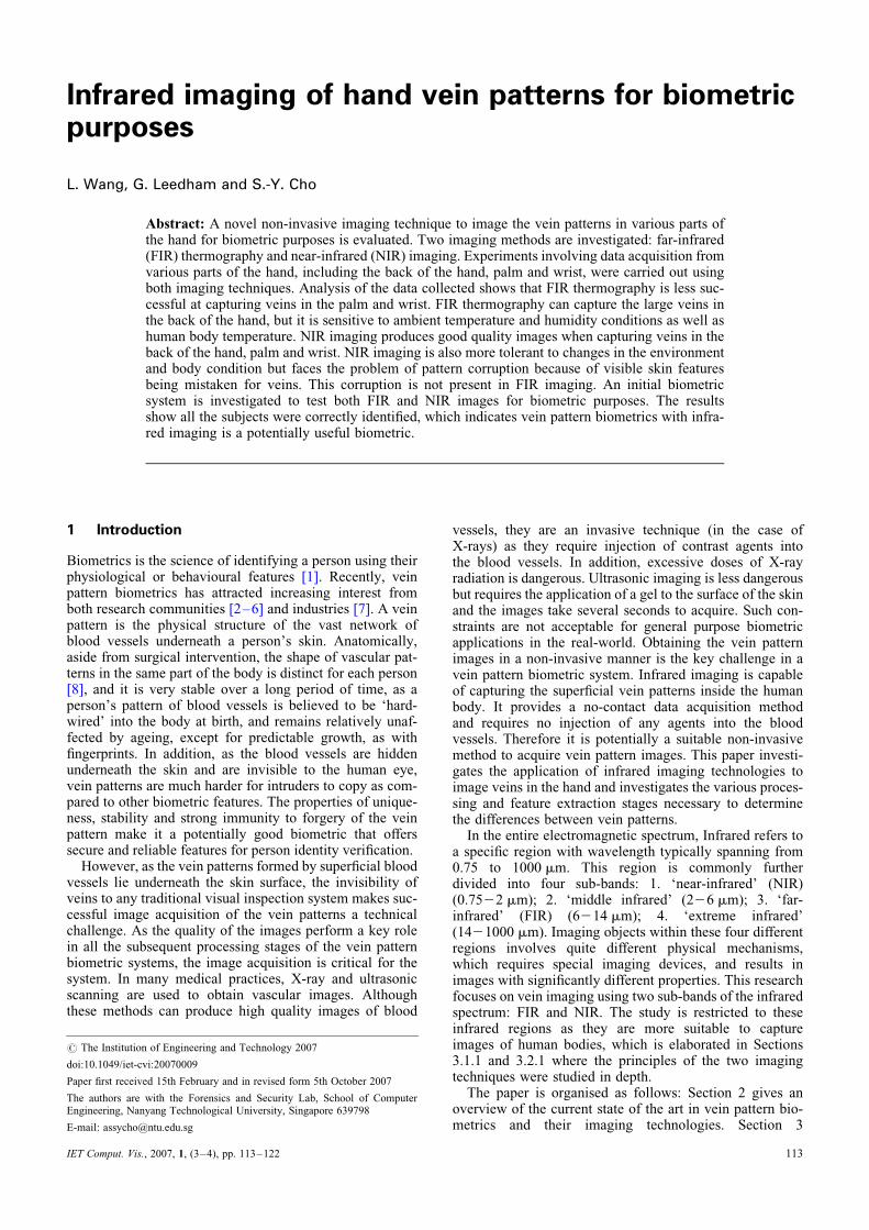
veins have higher temperature than the surroundingtissues. Therefore via thermal imaging, the images contain-ing the heat distribution of body parts can clearly display thestructure of the desired vein patterns, as can be seen inFig. 1. FIR imaging forms images using the infrared radi-ation emitted from the objects. No external lighting isrequired. Therefore FIR imaging does not suffer from illu-mination problems like many other imaging techniques.
3.1.2 System setup and image acquisition: In thisresearch, an NEC Thermo Tracer TS7302 was used as theFIR image acquisition device. It operates in the spectralrange of 8–14 mm and has a temperature resolution of0.088C and an image resolution of 320 (H) � 240 (V)pixels. The camera was mounted on a copy-stand andadjusted to a height of approximately 30 cm above thebase of the copy-stand. The camera was connected to aworkstation.During the FIR image acquisition, the subject placed one
hand on the base of the copystand with the back of the handfacing upwards so that the FIR camera can capture thetemperature profile of the back of the hand and transfer itto the workstation. On the workstation, the thermo analysersoftware converts the temperature data into 256 level grey-scale images for analysis in the subsequent stages.
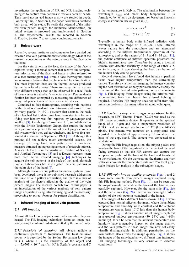
3.1.3 FIR vein image quality analysis: Figs. 1 and 2show some sample vein pattern images captured usingthis FIR imaging method. From Fig. 1, it can be seen thatthe major vascular network in the back of the hand is suc-cessfully captured. However, for the palm side (Fig. 2a)and the wrist area (Fig. 2b), there is no meaningful infor-mation of the vein patterns contained in the image.The images of four different hands shown in Fig. 1 were
captured in a normal office environment, where the ambienttemperature and humidity were constant and the ambienttemperature was at least 108C less than the human bodytemperature. Fig. 3 shows another set of images capturedin a tropical outdoor environment (30–348C and .80%humidity). It can be seen that the ambient temperature andhumidity have a negative impact on the image quality,and the vein patterns in these images are now not easilyvisually distinguishable. In addition, perspiration on theskin surface also affects the image quality. Fig. 4 showsthe images of the same hand at two different time instances.FIR imaging technology is very sensitive to externalconditions.
IET Comput. Vis., Vol. 1, No. 3–4, 2007
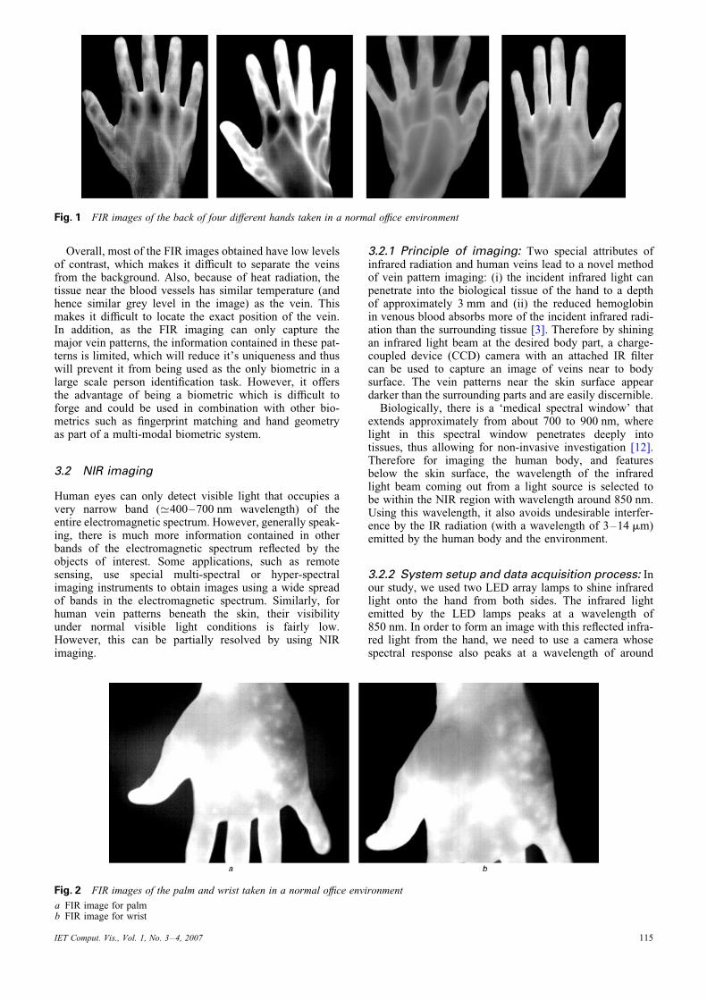
Fig. 1 FIR images of the back of four different hands taken in a normal office environment
Overall, most of the FIR images obtained have low levelsof contrast, which makes it difficult to separate the veinsfrom the background. Also, because of heat radiation, thetissue near the blood vessels has similar temperature (andhence similar grey level in the image) as the vein. Thismakes it difficult to locate the exact position of the vein.In addition, as the FIR imaging can only capture themajor vein patterns, the information contained in these pat-terns is limited, which will reduce it’s uniqueness and thuswill prevent it from being used as the only biometric in alarge scale person identification task. However, it offersthe advantage of being a biometric which is difficult toforge and could be used in combination with other bio-metrics such as fingerprint matching and hand geometryas part of a multi-modal biometric system.
3.2 NIR imaging
Human eyes can only detect visible light that occupies avery narrow band (’400–700 nm wavelength) of theentire electromagnetic spectrum. However, generally speak-ing, there is much more information contained in otherbands of the electromagnetic spectrum reflected by theobjects of interest. Some applications, such as remotesensing, use special multi-spectral or hyper-spectralimaging instruments to obtain images using a wide spreadof bands in the electromagnetic spectrum. Similarly, forhuman vein patterns beneath the skin, their visibilityunder normal visible light conditions is fairly low.However, this can be partially resolved by using NIRimaging.
IET Comput. Vis., Vol. 1, No. 3–4, 2007
3.2.1 Principle of imaging: Two special attributes ofinfrared radiation and human veins lead to a novel methodof vein pattern imaging: (i) the incident infrared light canpenetrate into the biological tissue of the hand to a depthof approximately 3 mm and (ii) the reduced hemoglobinin venous blood absorbs more of the incident infrared radi-ation than the surrounding tissue [3]. Therefore by shiningan infrared light beam at the desired body part, a charge-coupled device (CCD) camera with an attached IR filtercan be used to capture an image of veins near to bodysurface. The vein patterns near the skin surface appeardarker than the surrounding parts and are easily discernible.Biologically, there is a ‘medical spectral window’ that
extends approximately from about 700 to 900 nm, wherelight in this spectral window penetrates deeply intotissues, thus allowing for non-invasive investigation [12].Therefore for imaging the human body, and featuresbelow the skin surface, the wavelength of the infraredlight beam coming out from a light source is selected tobe within the NIR region with wavelength around 850 nm.Using this wavelength, it also avoids undesirable interfer-ence by the IR radiation (with a wavelength of 3–14 mm)emitted by the human body and the environment.
3.2.2 System setup and data acquisition process: Inour study, we used two LED array lamps to shine infraredlight onto the hand from both sides. The infrared lightemitted by the LED lamps peaks at a wavelength of850 nm. In order to form an image with this reflected infra-red light from the hand, we need to use a camera whosespectral response also peaks at a wavelength of around
Fig. 2 FIR images of the palm and wrist taken in a normal office environment
a FIR image for palmb FIR image for wrist
115
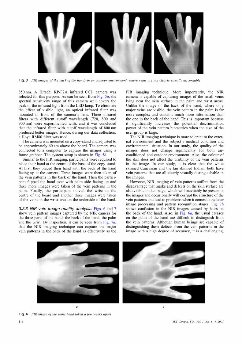
Fig. 3 FIR images of the back of the hands in an outdoor environment, where veins are not clearly visually discernable
850 nm. A Hitachi KP-F2A infrared CCD camera wasselected for this purpose. As can be seen from Fig. 5a, thespectral sensitivity range of this camera well covers thepeak of the infrared light from the LED lamp. To eliminatethe effect of visible light, an optical infrared filter wasmounted in front of the camera’s lens. Three infraredfilters with different cutoff wavelength (720, 800 and900 nm) were experimented with, and it was concludedthat the infrared filter with cutoff wavelength of 800 nmproduced better images. Hence, during our data collection,a Hoya RM80 filter was used.The camera was mounted on a copy-stand and adjusted to
be approximately 60 cm above the board. The camera wasconnected to a computer to capture the images using aframe grabber. The system setup is shown in Fig. 5b.Similar to the FIR imaging, participants were required to
place their hand at the centre of the base of the copy-stand.At first, they placed their hand with the back of the handfacing up at the camera. Three images were then taken ofthe vein patterns in the back of the hand. Then the partici-pant flipped the hand over with palm side facing up andthree more images were taken of the vein patterns in thepalm. Finally, the participant moved the wrist to thecentre of the board and another three images were takenof the veins in the wrist area on the underside of the hand.
3.2.3 NIR vein image quality analysis: Figs. 6 and 7show vein pattern images captured by the NIR camera forthe three parts of the hand: the back of the hand, the palmand the wrist. By inspection, it can be seen from Fig. 7a,that the NIR imaging technique can capture the majorvein patterns in the back of the hand as effectively as the
116
FIR imaging technique. More importantly, the NIRcamera is capable of capturing images of the small veinslying near the skin surface in the palm and wrist areas.Unlike the image of the back of the hand, where onlymajor veins are visible, the vein pattern in the palm is farmore complex and contains much more information thanthe one in the back of the hand. This is important becauseit significantly increases the potential discriminationpower of the vein pattern biometrics when the size of theuser group is large.The NIR imaging technique is more tolerant to the exter-
nal environment and the subject’s medical condition andenvironmental situation. In our study, the quality of theimages does not change significantly for both air-conditioned and outdoor environment. Also, the colour ofthe skin does not affect the visibility of the vein patternsin the image. In our study, it is clear that the whiteskinned Caucasian and the tan skinned Indian, both havevein patterns that are all clearly visually distinguishable inthe images.However, NIR imaging of vein patterns suffers from the
disadvantage that marks and defects on the skin surface arealso visible in the image, which will inevitably be present inthe images and occasionally will corrupt the structure of thevein patterns and lead to problems when it comes to the laterimage processing and pattern recognition stages. Fig. 7bshows confusion in the NIR images caused by hairs onthe back of the hand. Also, in Fig. 6a, the usual creaseson the palm of the hand are difficult to distinguish fromthe vein patterns. Although human beings are capable ofdistinguishing these defects from the vein patterns in theimage with a high degree of accuracy, it is a challenging,
Fig. 4 FIR image of the same hand taken a few weeks apart
IET Comput. Vis., Vol. 1, No. 3–4, 2007
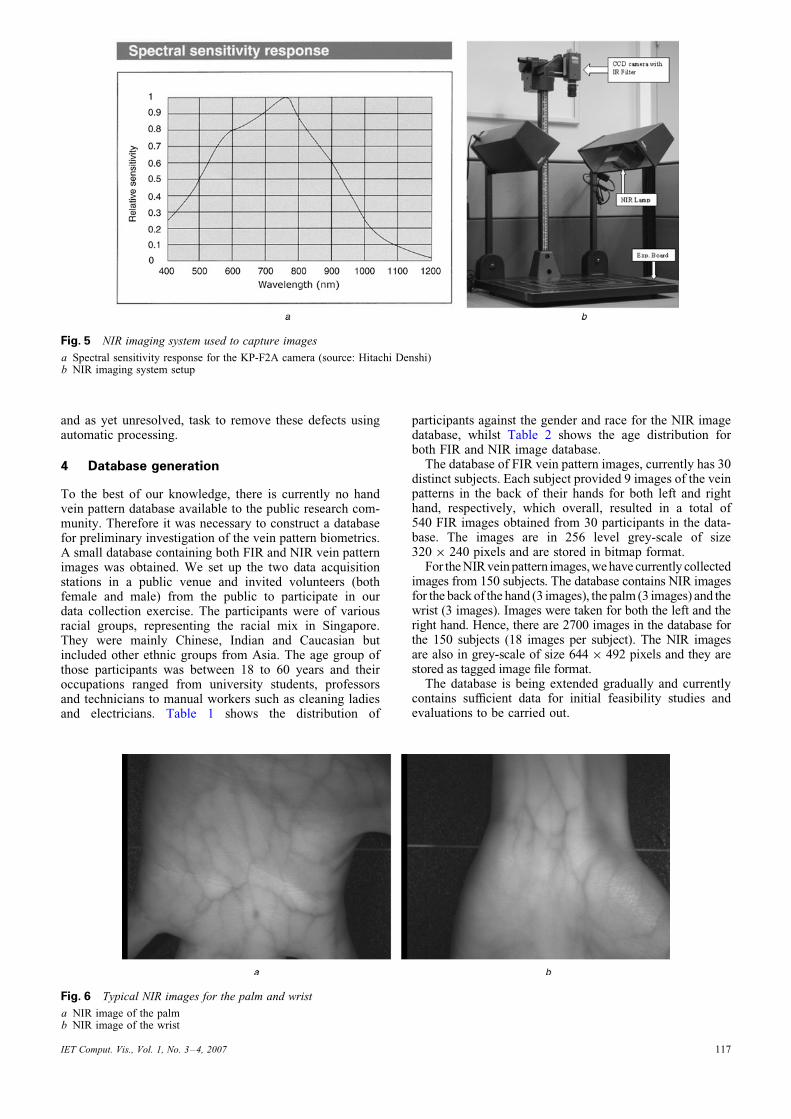
Fig. 5 NIR imaging system used to capture images
a Spectral sensitivity response for the KP-F2A camera (source: Hitachi Denshi)b NIR imaging system setup
and as yet unresolved, task to remove these defects usingautomatic processing.
4 Database generation
To the best of our knowledge, there is currently no handvein pattern database available to the public research com-munity. Therefore it was necessary to construct a databasefor preliminary investigation of the vein pattern biometrics.A small database containing both FIR and NIR vein patternimages was obtained. We set up the two data acquisitionstations in a public venue and invited volunteers (bothfemale and male) from the public to participate in ourdata collection exercise. The participants were of variousracial groups, representing the racial mix in Singapore.They were mainly Chinese, Indian and Caucasian butincluded other ethnic groups from Asia. The age group ofthose participants was between 18 to 60 years and theiroccupations ranged from university students, professorsand technicians to manual workers such as cleaning ladiesand electricians. Table 1 shows the distribution of
IET Comput. Vis., Vol. 1, No. 3–4, 2007
participants against the gender and race for the NIR imagedatabase, whilst Table 2 shows the age distribution forboth FIR and NIR image database.The database of FIR vein pattern images, currently has 30
distinct subjects. Each subject provided 9 images of the veinpatterns in the back of their hands for both left and righthand, respectively, which overall, resulted in a total of540 FIR images obtained from 30 participants in the data-base. The images are in 256 level grey-scale of size320 � 240 pixels and are stored in bitmap format.For theNIRveinpattern images,wehavecurrently collected
images from 150 subjects. The database contains NIR imagesfor the back of the hand (3 images), the palm (3 images) and thewrist (3 images). Images were taken for both the left and theright hand. Hence, there are 2700 images in the database forthe 150 subjects (18 images per subject). The NIR imagesare also in grey-scale of size 644 � 492 pixels and they arestored as tagged image file format.The database is being extended gradually and currently
contains sufficient data for initial feasibility studies andevaluations to be carried out.
Fig. 6 Typical NIR images for the palm and wrist
a NIR image of the palmb NIR image of the wrist
117
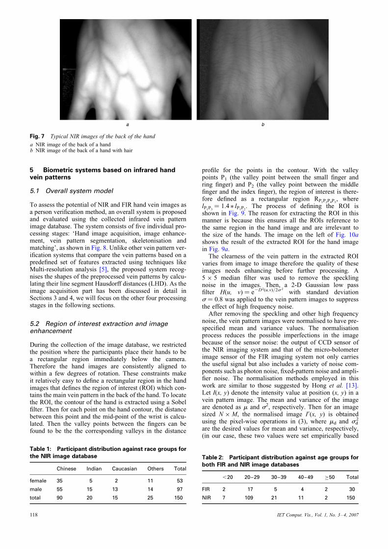
Fig. 7 Typical NIR images of the back of the hand
a NIR image of the back of a handb NIR image of the back of a hand with hair
5 Biometric systems based on infrared handvein patterns
5.1 Overall system model
To assess the potential of NIR and FIR hand vein images asa person verification method, an overall system is proposedand evaluated using the collected infrared vein patternimage database. The system consists of five individual pro-cessing stages: ‘Hand image acquisition, image enhance-ment, vein pattern segmentation, skeletonisation andmatching’, as shown in Fig. 8. Unlike other vein pattern ver-ification systems that compare the vein patterns based on apredefined set of features extracted using techniques likeMulti-resolution analysis [5], the proposed system recog-nises the shapes of the preprocessed vein patterns by calcu-lating their line segment Hausdorff distances (LHD). As theimage acquisition part has been discussed in detail inSections 3 and 4, we will focus on the other four processingstages in the following sections.
5.2 Region of interest extraction and imageenhancement
During the collection of the image database, we restrictedthe position where the participants place their hands to bea rectangular region immediately below the camera.Therefore the hand images are consistently aligned towithin a few degrees of rotation. These constraints makeit relatively easy to define a rectangular region in the handimages that defines the region of interest (ROI) which con-tains the main vein pattern in the back of the hand. To locatethe ROI, the contour of the hand is extracted using a Sobelfilter. Then for each point on the hand contour, the distancebetween this point and the mid-point of the wrist is calcu-lated. Then the valley points between the fingers can befound to be the the corresponding valleys in the distance
Table 1: Participant distribution against race groups forthe NIR image database
Chinese Indian Caucasian Others Total
female 35 5 2 11 53
male 55 15 13 14 97
total 90 20 15 25 150
118
profile for the points in the contour. With the valleypoints P1 (the valley point between the small finger andring finger) and P2 (the valley point between the middlefinger and the index finger), the region of interest is there-fore defined as a rectangular region RP1P2P4P3
, wherelP1P3
¼ 1.4 � lP1P2. The process of defining the ROI is
shown in Fig. 9. The reason for extracting the ROI in thismanner is because this ensures all the ROIs reference tothe same region in the hand image and are irrelevant tothe size of the hands. The image on the left of Fig. 10ashows the result of the extracted ROI for the hand imagein Fig. 9a.The clearness of the vein pattern in the extracted ROI
varies from image to image therefore the quality of theseimages needs enhancing before further processing. A5 � 5 median filter was used to remove the specklingnoise in the images. Then, a 2-D Gaussian low passfilter H(u, v) ¼ e2D2(u,v)/2s 2
with standard deviations ¼ 0.8 was applied to the vein pattern images to suppressthe effect of high frequency noise.After removing the speckling and other high frequency
noise, the vein pattern images were normalised to have pre-specified mean and variance values. The normalisationprocess reduces the possible imperfections in the imagebecause of the sensor noise: the output of CCD sensor ofthe NIR imaging system and that of the micro-bolometerimage sensor of the FIR imaging system not only carriesthe useful signal but also includes a variety of noise com-ponents such as photon noise, fixed-pattern noise and ampli-fier noise. The normalisation methods employed in thiswork are similar to those suggested by Hong et al. [13].Let I(x, y) denote the intensity value at position (x, y) in avein pattern image. The mean and variance of the imageare denoted as m and s2, respectively. Then for an imagesized N � M, the normalised image I0(x, y) is obtainedusing the pixel-wise operations in (3), where md and sd
2
are the desired values for mean and variance, respectively,(in our case, these two values were set empirically based
Table 2: Participant distribution against age groups forboth FIR and NIR image databases
,20 20–29 30–39 40–49 �50 Total
FIR 2 17 5 4 2 30
NIR 7 109 21 11 2 150
IET Comput. Vis., Vol. 1, No. 3–4, 2007
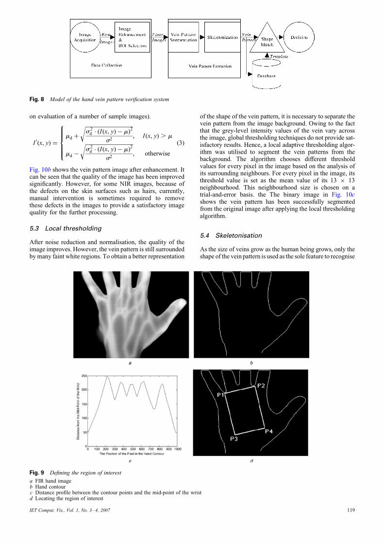
Fig. 8 Model of the hand vein pattern verification system
on evaluation of a number of sample images).
I 0(x, y) ¼md þ
ffiffiffiffiffiffiffiffiffiffiffiffiffiffiffiffiffiffiffiffiffiffiffiffiffiffiffiffiffiffiffiffiffiffiffiffis 2d � (I(x, y)� m)2
s2
r, I(x, y) . m
md �
ffiffiffiffiffiffiffiffiffiffiffiffiffiffiffiffiffiffiffiffiffiffiffiffiffiffiffiffiffiffiffiffiffiffiffiffis 2d � (I(x, y)� m)2
s2
r, otherwise
8>>><>>>:
(3)
Fig. 10b shows the vein pattern image after enhancement. Itcan be seen that the quality of the image has been improvedsignificantly. However, for some NIR images, because ofthe defects on the skin surfaces such as hairs, currently,manual intervention is sometimes required to removethese defects in the images to provide a satisfactory imagequality for the further processing.
5.3 Local thresholding
After noise reduction and normalisation, the quality of theimage improves. However, the vein pattern is still surroundedbymany faint white regions. To obtain a better representation
IET Comput. Vis., Vol. 1, No. 3–4, 2007
of the shape of the vein pattern, it is necessary to separate thevein pattern from the image background. Owing to the factthat the grey-level intensity values of the vein vary acrossthe image, global thresholding techniques do not provide sat-isfactory results. Hence, a local adaptive thresholding algor-ithm was utilised to segment the vein patterns from thebackground. The algorithm chooses different thresholdvalues for every pixel in the image based on the analysis ofits surrounding neighbours. For every pixel in the image, itsthreshold value is set as the mean value of its 13 � 13neighbourhood. This neighbourhood size is chosen on atrial-and-error basis. the The binary image in Fig. 10cshows the vein pattern has been successfully segmentedfrom the original image after applying the local thresholdingalgorithm.
5.4 Skeletonisation
As the size of veins grow as the human being grows, only theshape of the vein pattern is used as the sole feature to recognise
Fig. 9 Defining the region of interest
a FIR hand imageb Hand contourc Distance profile between the contour points and the mid-point of the wristd Locating the region of interest
119
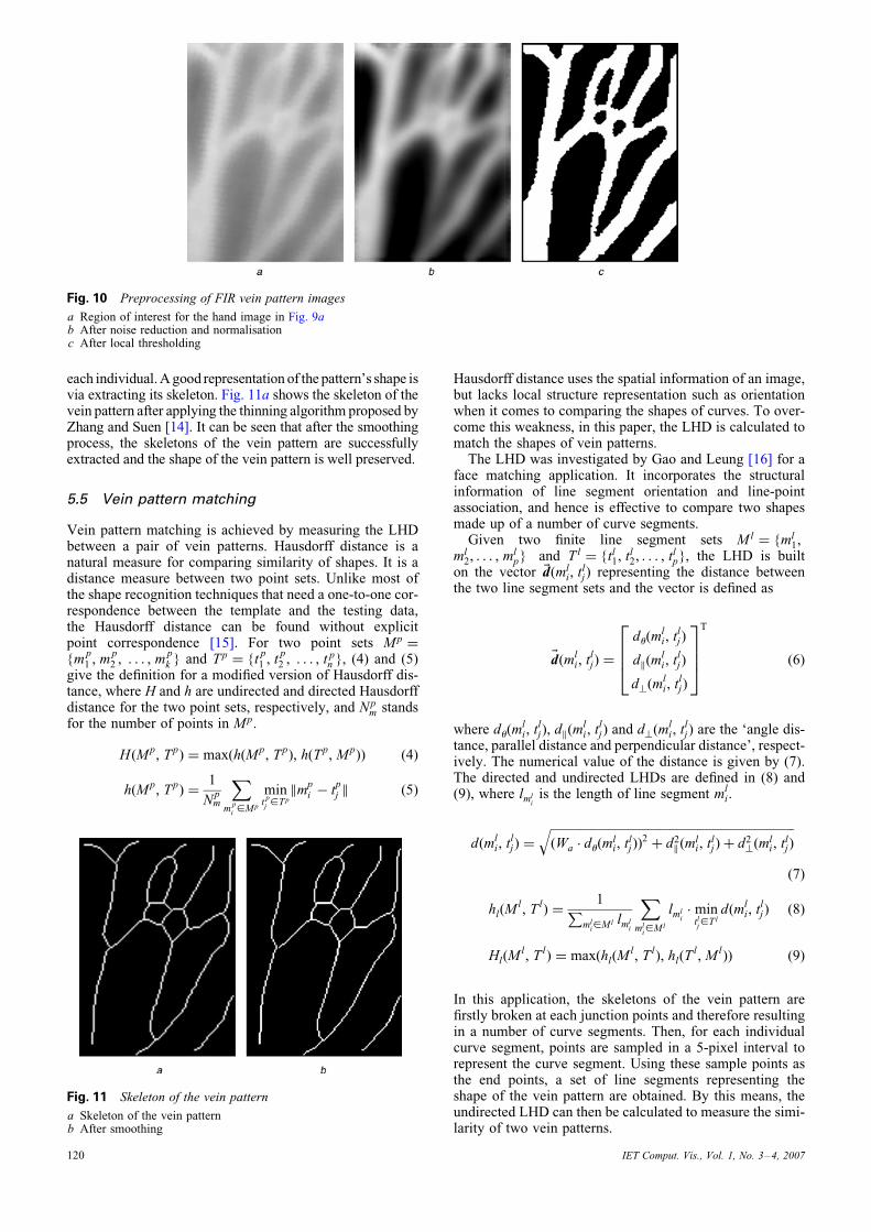
Fig. 10 Preprocessing of FIR vein pattern images
a Region of interest for the hand image in Fig. 9ab After noise reduction and normalisationc After local thresholding
each individual.Agood representation of the pattern’s shape isvia extracting its skeleton. Fig. 11a shows the skeleton of thevein pattern after applying the thinning algorithm proposed byZhang and Suen [14]. It can be seen that after the smoothingprocess, the skeletons of the vein pattern are successfullyextracted and the shape of the vein pattern is well preserved.
5.5 Vein pattern matching
Vein pattern matching is achieved by measuring the LHDbetween a pair of vein patterns. Hausdorff distance is anatural measure for comparing similarity of shapes. It is adistance measure between two point sets. Unlike most ofthe shape recognition techniques that need a one-to-one cor-respondence between the template and the testing data,the Hausdorff distance can be found without explicitpoint correspondence [15]. For two point sets Mp ¼
{mp1 , m
p2 , . . . , m
pk } and Tp ¼ {t
p1 , t
p2 , . . . , t p
n }, (4) and (5)give the definition for a modified version of Hausdorff dis-tance, where H and h are undirected and directed Hausdorffdistance for the two point sets, respectively, and Np
m standsfor the number of points in Mp.
H(Mp, Tp) ¼ max(h(Mp, Tp), h(Tp, Mp)) (4)
h(Mp, Tp) ¼1
Npm
Xm
p
i[Mp
mint
p
j[Tp
kmpi � t
pj k (5)
Fig. 11 Skeleton of the vein pattern
a Skeleton of the vein patternb After smoothing
120
Hausdorff distance uses the spatial information of an image,but lacks local structure representation such as orientationwhen it comes to comparing the shapes of curves. To over-come this weakness, in this paper, the LHD is calculated tomatch the shapes of vein patterns.The LHD was investigated by Gao and Leung [16] for a
face matching application. It incorporates the structuralinformation of line segment orientation and line-pointassociation, and hence is effective to compare two shapesmade up of a number of curve segments.Given two finite line segment sets Ml ¼ {ml
1,ml
2, . . . , mlp} and Tl ¼ {tl
1, tl2, . . . , tl
p}, the LHD is builton the vector ~d(ml
i, tlj) representing the distance between
the two line segment sets and the vector is defined as
~d(mli, t
lj) ¼
du(mli, tl
j)
dk(mli, t
lj)
d?(mli, t
lj)
2664
3775
T
(6)
where du(mli, tl
j), dk(mli, tl
j) and d?(mli, tl
j) are the ‘angle dis-tance, parallel distance and perpendicular distance’, respect-ively. The numerical value of the distance is given by (7).The directed and undirected LHDs are defined in (8) and(9), where lml
iis the length of line segment ml
i.
d(mli, tl
j) ¼
ffiffiffiffiffiffiffiffiffiffiffiffiffiffiffiffiffiffiffiffiffiffiffiffiffiffiffiffiffiffiffiffiffiffiffiffiffiffiffiffiffiffiffiffiffiffiffiffiffiffiffiffiffiffiffiffiffiffiffiffiffiffiffiffiffiffiffiffiffiffiffiffiffiffiffiffiffiffiffiffi(Wa � du(m
li, tl
j))2 þ d2
k (mli, tl
j)þ d2?(m
li, tl
j)
q
(7)
hl(Ml, Tl) ¼
1Pml
i[Ml lml
i
Xml
i[Ml
lmli� min
tlj[Tl
d(mli, tl
j) (8)
Hl(Ml, Tl) ¼ max(hl(M
l, Tl), hl(Tl, Ml)) (9)
In this application, the skeletons of the vein pattern arefirstly broken at each junction points and therefore resultingin a number of curve segments. Then, for each individualcurve segment, points are sampled in a 5-pixel interval torepresent the curve segment. Using these sample points asthe end points, a set of line segments representing theshape of the vein pattern are obtained. By this means, theundirected LHD can then be calculated to measure the simi-larity of two vein patterns.
IET Comput. Vis., Vol. 1, No. 3–4, 2007
6 Experiments
Testing was firstly carried out on our FIR vein pattern imagedatabase. We chose the left hand image data, which consistsof 270 images from 30 people (9 from each person). Prior totesting, three images for each person were selected ran-domly to form the class or training templates for thatperson. During the verification stage, three undirectedLHDs (H1, H2, H3) were computed between the incomingvein pattern image and the three template images. Theaverage value H 0 of H1, H2 and H3 was then calculated,which is the similarity measure between the incomingvein pattern and the target class. Fig. 12 shows the distri-bution of the genuine and intruder accesses against thevalue H 0. It can be easily seen from Fig. 12 that thesmaller H 0, the higher the probability the vein patternbelong to the genuine class. By choosing H0 ¼ 9.0 to bethe threshold value, the system achieves 0% false accep-tance rate and 0% false rejection rate for all the 270images in both the testing set (containing 180 images) andthe template set (containing 90 images).The same experiment was also carried out on the NIR
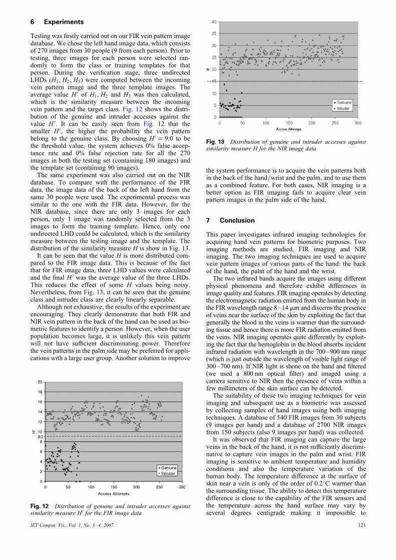
database. To compare with the performance of the FIRdata, the image data of the back of the left hand from thesame 30 people were used. The experimental process wassimilar to the one with the FIR data. However, for theNIR database, since there are only 3 images for eachperson, only 1 image was randomly selected from the 3images to form the training template. Hence, only oneundirected LHD could be calculated, which is the similaritymeasure between the testing image and the template. Thedistribution of the similarity measure H is show in Fig. 13.It can be seen that the value H is more distributed com-
pared to the FIR image data. This is because of the factthat for FIR image data, three LHD values were calculatedand the final H 0 was the average value of the three LHDs.This reduces the effect of some H values being noisy.Nevertheless, from Fig. 13, it can be seen that the genuineclass and intruder class are clearly linearly separable.Although not exhaustive, the results of the experiment are
encouraging. They clearly demonstrate that both FIR andNIR vein pattern in the back of the hand can be used as bio-metric features to identify a person. However, when the userpopulation becomes large, it is unlikely this vein patternwill not have sufficient discriminating power. Thereforethe vein patterns in the palm side may be preferred for appli-cations with a large user group. Another solution to improve
Fig. 12 Distribution of genuine and intruder accesses againstsimilarity measure H0 for the FIR image data
IET Comput. Vis., Vol. 1, No. 3–4, 2007
the system performance is to acquire the vein patterns bothin the back of the hand/wrist and the palm, and to use themas a combined feature. For both cases, NIR imaging is abetter option as FIR imaging fails to acquire clear veinpattern images in the palm side of the hand.
7 Conclusion
This paper investigates infrared imaging technologies foracquiring hand vein patterns for biometric purposes. Twoimaging methods are studied, FIR imaging and NIRimaging. The two imaging techniques are used to acquirevein pattern images of various parts of the hand: the backof the hand, the palm of the hand and the wrist.The two infrared bands acquire the images using different
physical phenomena and therefore exhibit differences inimage quality and features. FIR imaging operates by detectingthe electromagnetic radiation emitted from the human body inthe FIR wavelength range 8–14 mm and discerns the presenceof veins near the surface of the skin by exploiting the fact thatgenerally the blood in the veins is warmer than the surround-ing tissue and hence there is more FIR radiation emitted fromthe veins. NIR imaging operates quite differently by exploit-ing the fact that the hemoglobin in the blood absorbs incidentinfrared radiation with wavelength in the 700–900 nm range(which is just outside the wavelength of visible light range of300–700 nm). If NIR light is shone on the hand and filtered(we used a 800 nm optical filter) and imaged using acamera sensitive to NIR then the presence of veins within afew millimeters of the skin surface can be detected.The suitability of these two imaging techniques for vein
imaging and subsequent use as a biometric was assessedby collecting samples of hand images using both imagingtechniques. A database of 540 FIR images from 30 subjects(9 images per hand) and a database of 2700 NIR imagesfrom 150 subjects (also 9 images per hand) was collected.It was observed that FIR imaging can capture the large
veins in the back of the hand, it is not sufficiently discrimi-native to capture vein images in the palm and wrist. FIRimaging is sensitive to ambient temperature and humidityconditions and also the temperature variation of thehuman body. The temperature difference at the surface ofskin near a vein is only of the order of 0.28C warmer thanthe surrounding tissue. The ability to detect this temperaturedifference is close to the capability of the FIR sensors andthe temperature across the hand surface may vary byseveral degrees centigrade making it impossible to
Fig. 13 Distribution of genuine and intruder accesses againstsimilarity measure H for the NIR image data
121
accurately detect all veins in one image. Each image willresult in flaring or ‘white-out’ of some parts of the image,as can be seen in Fig. 1. FIR imaging is difficult and thefact that only 30 of about 150 subjects imaged resulted inimages which could be used for biometric comparison illus-trates the difficulty in obtaining good FIR images of veinsnear the surface of the skin.NIR imaging was observed to perform better than FIR
imaging by producing good quality images when capturingvein patterns in the back of the hand, palm and the wrist. Itis more tolerant to the changes in the ambient environ-mental and body temperature conditions. However, NIRimaging faces the problem of corruption from the skin fea-tures such as hair, cuts, external marks and palm prints. FIRdoes not suffer from this problem as the images are notaffected by visible light.An initial biometric system based on the skeletonised
vein patterns and their Hausdorff distance was constructedand investigated to test the discrimination using both FIRand NIR vein pattern data set. The experimental results indi-cated that all the testing subjects can be correctly identified,which shows vein pattern biometrics with infrared imagingis a potentially useful biometric. This paper does notattempt to determine the best features to extract from theinfrared images.In the future, the research will focus on the NIR imaging
and use of these images for vein pattern biometrics. Moreinvestigation is needed in all stages of the subsequentprocessing of the NIR images. This includes preprocessingto enhance the images and better extract the vein lines fromthe images while filtering out other non-vein lines. Furtherresearch is needed to determine and select an appropriatefeature set that can be extracted which best represent theuniqueness of vein patterns. Lastly, as the details of veins islimited to the larger veins, the amount of detail is limited ineach image. It is likely that hand vein pattern biometricswill most effectively be used in conjunction with otherbiometrics such as palm prints, finger prints and handgeometry in a multi-modal biometric system.
122
8 References
1 Ratha, N.K., Senior, A., and Bolle, R.M.: ‘Tutorial on automatedbiometrics’. Proc. Int. Conf. Advances in Pattern Recognition, Riode Janeiro, Brazil, March 2001
2 Wang, L., and Leedham, C.G.: ‘A thermal hand vein patternverification system’. Proc. Int. Conf. Advances in PatternRecognition, Bath, UK, August 2005
3 Cross, J.M., and Smith, C.L.: ‘Thermographic imaging ofsubcutaneous vascular network of the back of the hand forbiometric identification’. Proc. IEEE 29th Int. Carnahan Conf.Security Technology, Sanderstead, Surrey, UK, October 1995
4 Im, S.-K., Park, H.-M., Kim, S.-W., Chung, C.-K., and Choi, H.-S.:‘Improved vein pattern extracting algorithm and itsimplementation’. Digest of Technical Papers of Int. Conf. ConsumerElectronics, June 2000
5 Lin, C.-L., and Fan, K.-C.: ‘Biometric verification using thermalimages of palm-dorsa vein patterns’, IEEE Trans. Circuits Syst.Video Technol., 2004, 14, (2), pp. 199–213
6 Miura, N., Nagasaka, A., and Miyatake, T.: ‘Feature extraction offinger-vein patterns based on repeated line tracking and itsapplication to personl identification’, Mach. Vis. Appl., 2004, 15,pp. 194–203
7 Fujitsu Laboratories Ltd: ‘Fujitsu Laboratories develops technologyfor world’s first contactless palm vein pattern biometricauthentication system’. [Online March 2003], available at: http://pr.fujitsu.com/en/news/2003/03/31.html
8 Jain, A., Bolle, R.M., and Pankanti, S.: ‘Biometrics: personalidentification in networked society’ (Kluwer Academic Publishers,Dordrecht, 1999)
9 MacGregor, P., andWelford, R.: ‘Veincheck: imaging for security andpersonnel identification’, Adv. Imaging, 1991, 6, (7), pp. 52–56
10 Hawkes, P.L., and Clayden, D.O.: ‘Veincheck research for automaticidentification of people’. Presented at the Hand and FingerprintSeminar at NPL, September 1993
11 Harris, D.C.: ‘Infrared window and dome materials’ (SPIE,Bellingham, WA, 1992)
12 Fantini, S., and Franceschini, M.A.: ‘Frequency-domain techniquesfor tissue spectroscopy and imaging’, in Tuchin, V.V. (Ed.):‘Handbook of optical biomedical diagnostics’ (SPIE Press,Bellingham, WA, 2002), Chap. 7, pp. 405–453
13 Hong, L., Wan, Y., and Jain, A.: ‘Fingerprint image enhancement:algorithm and performance evaluation’, IEEE Trans. Pattern Anal.Mach. Intell., 1998, 20, (8), p. 777–789
14 Suen, C.Y., and Zhang, T.Y.: ‘A fast parallel algorithm for thinningdigital patterns’, Commun. ACM, 1984, 27, (3), pp. 236–239
15 Ruchlidge, W.J.: ‘Efficiently locating objects using Hausdorffdistance’, Int. J. Comput. Vis., 1997, 24, pp. 251–270
16 Gao, Y., and Leung, M.K.H.: ‘Line segment Hausdorff distance onface matching’, Pattern Recognit., 2002, 35, pp. 361–371
IET Comput. Vis., Vol. 1, No. 3–4, 2007


![Finger-vein biometric identi cation using convolutional neural … · resulted in an accuracy of 98% and processing time was 0.015 s. In 2011, Wu and Liu [14] proposed a nger-vein](https://img.pdfslide.us/doc/110x75/6036661dddddec49195b2339/finger-vein-biometric-identi-cation-using-convolutional-neural-resulted-in-an-accuracy.jpg)