Embed Size (px)
Citation preview

Infrared He-Xe laser interferometry for measuring length
Hirokazu Matsumoto
A technique is described for determining absolute lengths up to 3 m from measurement of the interferencefringe fractions for multiple wavelengths. The required accuracies of the wavelength ratio and fringe frac-
tion reading are analyzed. To satisfy the accuracies, a low-cost simply stabilized He-Xe laser, operating si-multaneously at two wavelengths, 3.51 and 3.37 Am, was developed. Using this laser the preliminary mea-
surement of the wavelength ratio was made interferometrically with the length standard of a gauge block.
1. Introduction
In precise measurement of length it is convenient touse the method of excess fractions with multiplewavelength interference. At present, cadmium, mer-cury, or krypton atoms are such a light source, but theycannot be applied to the measurement of lengths greaterthan several tens of centimeters because of their poorcoherency. 1
A single longitudinal mode laser has very good co-herence, 2 but in the visible region when oscillating atmultiple wavelengths it is difficult to maintain a singlelongitudinal mode,3 '4 and several laser sources, each ofwhich is stabilized to a high degree of accuracy, areneeded for achieving the method of excess fractions.Therefore, visible multiple wavelength interferometryis difficult for long length measurement. A He-Xe laseroscillates at several wavelengths in the 3-tim region5 andoperates in a single longitudinal mode without a modeselector because of its high gain and long wavelength.In particular, the laser lines at 3.51 and 3.37 ,im are, itis hoped, for interferometric length measurement be-cause of their different transitions between atomic en-ergy levels and their good atmospheric transmission.Optical elements and detectors in this wavelength re-gion are of low cost. The 3.51-,gm line of the He-Xelaser has been frequency stabilized with an accuracy ofbetter than 1 X 10⁻⁹ by using a H2 CO absorptionline.6
Multiple wavelength laser interferometry for lengthmeasurement was studied for reading interference or-ders.7 8 In the measurement of long length, the accu-racy of the laser wavelength used is also important.Although an overall accuracy of 1 X 10⁻⁷ is sufficient forlength measurement, much higher accuracy is requiredin the laser wavelength for achieving the method ofexcess fractions. However, the required accuracy is notin either of the two wavelengths but in their ratio. Asimple method, which uses a two-wavelength simulta-neously oscillating He-Xe laser, is proposed for mea-suring absolute lengths up to 3 m. The stabilization ofthe wavelength is easily done by a method based on thedependence of output power on cavity tuning.9-'2
II. Analysis
A. Interferometry
Let us consider the problem of determining the lengthfrom the interference order fractions of the fringes ob-tained with two wavelengths Xi, i = 1,2. The interfer-ence order equation for length L is simply given by
L = (M, + m + ei) Xi/2, (1)
where Mi and m are the integral numbers of the inter-ference orders known by other means and determinedby the method of excess fractions, respectively, and ciis the measured fractions of the interference orders.From Eq. (1) the following equation is obtained:
m = [(M2 + 2 )-(M + E1) f(f - 1), (2)
where f is the wavelength ratio X1/X2. The uncertaintyon m will be such that
The author is with National Research Laboratory of Metrology,1-1-4 Umezono, Sakura-mura, Niihari-gun, Ibaraki 305, Japan.
Received 7 July 1980.0003-6935/81/020231-04$00.50/0.© 1981 Optical Society of America.
(3)am = 2f __+ 2L _ 6ff-i Xi f-iwhere bE = I be, I= 1 E2/f 1, and bE and 6f are the errorson fraction and ratio, respectively. For determining thenumber m uniquely, the condition I bm I < 1/2 must hold.
15 January 1981 / Vol. 20, No. 2 / APPLIED OPTICS 231
Gain curve
i \ NiN. 1 WI 1 -1 N2 N2
Mode order number
Fig. 1. Relation of laser gain curves and cavity modes.
-200 mm --- I Reservoir
Fig. 2. Schematic of the He-Xe laser developed.
Generally speaking, as the wavelength ratio f ap-proaches unity, the required accuracies of reading theinterference order and the ratio between the laserwavelengths become more severe. On the other hand,the length determined by the excess fractions methodtakes longer, and the preliminary measurement by othermethods becomes simpler since it equals the syntheticwavelength X/(f - 1). Therefore, it is possible tomeasure long lengths.
B. Examples
Now, applying the visible wavelengths A = 0.633 mand 2 = 0.612,um to Eq. (3) at a length of 3 m, we findthe relations be < 0.008 = 0.003 m and f < 2 X 10⁻⁹from the condition bm < 1/2. It is therefore difficultto satisfy the relations with a visible interferometer.
If A = 3.51 jim and 2 = 3.37 Aim, we obtain therelations be < 0.010 = 0.018 m and f < 1.2 X 10⁻⁸ at3 m. The former relation is sufficiently satisfied by theuse of the infrared interferometer already reported.12
The relation of the latter is somewhat severe becausethe two wavelengths vary independently with time.However, this is relieved if the two wavelengths simul-taneously oscillate in the same cavity as shown in Fig.1. In this case, the mode order numbers of the lasercavity Ni are approximated by
Ni = 2Di/Xi,
where Di is the optical cavity length at wavelength Xi.The difference (D2 - D1) is due to the dependence ofthe refractive indices on the wavelength of substancesin the cavity, mainly, the fused quartz of the plasmatube windows. From Eq. (4), the wavelength ratio f isgiven by D2Ni/DiN 2 . The laser cavity is designed sothat change of cavity length is very small. Let thelengths D and D2 be linear functions of time t andchange by an amount AD. If the mode order numbersN 1 and N2 are not changed, i.e., the change of the cavity
length is less than X1/4, the variation bf in f is approxi-mated by fAD(D 2 -D )/DlD 2. Accordingly, the un-certainty bfIf is <1 X 10⁻¹⁰ since the difference (D2 -
D1 ) is less than several micrometers, and the variationAD is stabilized to less than A1/50 where the cavitylength is -56 cm. Next, if each of the mode ordernumbers is increased by 1 and the wavelength stabili-zation is carried out with Xi, we obtain
/ + 6t (D1 + AD + X1/2)(N2 + 1)(D2 + AD + X1/2)(N + 1)
=f f1+ AD(D 2 D) I+ X2-A.DjD2 2D2
(5)
Accordingly, the uncertainty of 5f/f becomes nearly 1.3X 10⁻⁷, which is reduced by the mode pulling effect.13
This value is too large to achieve the method of excessfractions. However, such a change can be confirmedfrom the relation between the locations of the oscillationwavelengths in the gain curves, and the cavity length ispiezoelectrically tuned so that the mode order numbersare returned to the original numbers (see Fig. 5).Therefore, the uncertainty 3f/f is <1 X 10⁻¹⁰.
Finally, the uncertainty of the wavelength ratio issmall enough in simultaneous oscillation. The ratiomust be measured to an accuracy of better than 1.2 X10⁻⁸ in the air near normal conditions. This would beperformed by measuring a long gauge block of knownlength with the infrared interferometer described later.The ratio is not influenced by the variation of the airrefractive index because the refractive index of air at3.51 m does not differ from that at 3.37 jum by morethan 2 X 10⁻⁸, and its variation usually is <+1 X10-5.12,14
I1. Experiment
The He-Xe laser developed is shown in Figs. 2 and3. The laser with 6 Pa of Xe and 130 Pa of He operatesin the TEMOO mode at the 3.51- and 3.37-Aim lines. Theoutput power is 0.5 mW with a direct discharge cur-rent of 5 mA. A large gas reservoir (1.3 liters) coun-teracts the gas cleanup problem. The cavity, whichconsists of a dielectric coated flat mirror and a sphericalreflector mounted on a piezoelectric translator (PZT),is supported with thermally insensitive 59-cm long Invarbars. The aluminum alloy mirror mount is designed tocancel out the thermal expansion of the Invar, so thatthe thermal expansion coefficient of the cavity is slightly
(4)
Fig. 3. View of the He-Xe laser.
232 APPLIED OPTICS / Vol. 20, No. 2 / 15 January 1981
. I
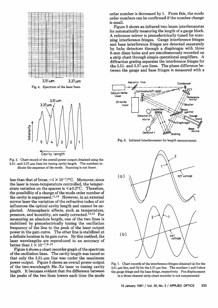
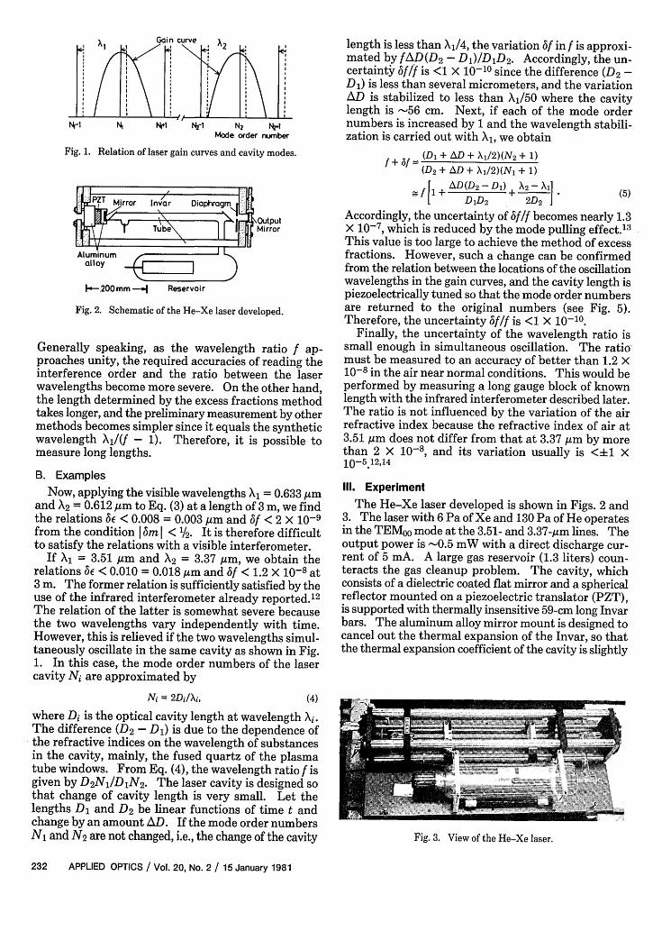
Fig. 4. Spectrum of the laser lines.
3.51 um3.37 jum/
; 5 4 3 2 1
Cavity lengthFig. 5. Chart record of the overall power output obtained using the3.51- and 3.37-sum lines for tuning cavity length. The numbers in-
dicate the sequence of the mode. Scanning is not linear.
less than that of Invar, -1 X 10- 7/ 0 C. Moreover, sincethe laser is room-temperature controlled, the temper-ature variation on the spacers is <+0.2 0C. Therefore,the possibility of a change of the mode order number ofthe cavity is suppressed. 1 1 14 However, in an externalmirror laser the variation of the refractive index of airinfluences the optical cavity length and cannot be ne-glected. Atmospheric effects, such as temperature,pressure, and humidity, are easily corrected.12"15 Formeasuring an absolute length, one of the two lines isstabilized by piezoelectrically tuning the oscillationfrequency of the line to the peak of the laser outputpower in the gain curve. The other line is stabilized ata definite location in its gain curve. By this method, thelaser wavelengths are reproduced to an accuracy ofbetter than 1 X 10-7.9-12
Figure 4 shows a chart-recorder graph of the spectrumof the oscillation lines. The cavity length was tuned sothat only the 3.51-pim line was under the maximumpower output. Figure 5 shows an overall power outputof the two-wavelength He-Xe laser vs tuning cavitylength. It becomes evident that the difference betweenthe peaks of the two lines lowers each time the mode
order number is decreased by 1. From this, the modeorder numbers can be confirmed if the number changeis small.
Figure 6 shows an infrared two-beam interferometerfor automatically measuring the length of a gauge block.A reference mirror is piezoelectrically tuned for scan-ning interference fringes. Gauge interference fringesand base interference fringes are detected separatelyby InAs detectors through a diaphragm with three8-mm diam holes and are simultaneously recorded ona strip chart through simple operational amplifiers. Adiffraction grating separates the interference fringes forthe 3.51- and 3.37-Aim lines. The phase difference be-tween the gauge and base fringes is measured with a
Metallic film
Fig. 6. Infrared interferometer for length measurement.
(a)
(b)
Fig. 7. Chart records of the interference fringes obtained (a) for the3.51-tim line, and (b) for the 3.37-ttm line. The numbers 1 and 2 showthe gauge fringe and the base fringe, respectively. Pen displacement
in a three-channel strip-chart recorder is not compensated.
15 January 1981 / Vol. 20, No. 2 / APPLIED OPTICS 233
I l. .J I .I I.lL1 I _J _ l.-I
3.51 um 3.37pmCondenser

Table I. Experimental Results
Fractions RatioNo. El C2 f
1 0.990 0.396 1.04168502 93 401 543 87 385 304 90 387 275 92 406 706 90 402 657 94 399 478 89 391 409 84 385 38
Mean 0.990 0.395 1.0416847
Standard deviation 0.0029 0.0075 0.00000139
resolution of better than 1° in phase. The nonlinearityin scan is eliminated by the use of the fringe-readingmethod.'2, 6
Using this laser interferometer, the preliminary ex-periment was made to confirm this method. A 7-mmlong gauge block, whose absolute length was knownfrom a visible gauge block interferometer,' was used asthe standard length. Figure 7 shows chart-recordergraphs of the interference fringes obtained. Themeasured fractions e and 62 for the 3.50799- and3.36761-jim wavelengths and the calculated wavelengthratio f are shown in Table I. It becomes evident thatthe errors on fractions E1 and 2 are <0.01 in standarddeviation. Furthermore, the error on the ratio f is halfof the sum of the errors on e and 2 because the errorsrelated to both el and 2 are canceled. This increasesthe reliability in determining the length by the methodof excess fractions.
The synthetic wavelength obtained using this He-Xelaser is long, -80 Am. The measurement of lengths ofseveral meters should be interferometrically achievedby this method with a precision of 0.01 jim.
The author wishes to thank S. Seino for helpful dis-cussions and suggestions.
References1. Y. Sakurai and S. Seino, Bull. Natl. Res. Lab. Metrol. Tokyo 14,
34 (1967).2. H. Welling and B. Wellegehausen, Appl. Opt. 11, 1986 (1972).3. P. Cerez and S. J. Bennett, Opt. Commun. 25, 1079 (1979).4. F. Spieweck, IEEE Trans. Instrum. Meas. IM-27, 398 (1978).5. W. L. Faust, R. A. McFarlane, C. K. N. Patel, and C. G. B. Garrett,
Appl. Phys. Lett. 1, 85 (1962).6. M. Ohtsu and T. Tako, Jpn. J. Appl. Phys. 17, 2169 (1978).7. C. R. Tilford, Appl. Opt. 16, 1857 (1977).8. G. L. Bourdet and A. G. Orszag, Appl. Opt. 18, 225 (1979).9. W. R. C. Rowley and D. C. Wilson, Nature London 200, 745
(1963).10. W. R. Bennett, Jr., S. F. Jacobs, J. T. LaTourrette, and P. Rabi-
nowitz, Appl. Phys. Lett. 5, 56 (1964).11. K. D. Mielenz, R. B. Stephens, K. E. Gillilland, and K. F. Nefflen,
J. Opt. Soc. Am. 56, 156 (1966).12. H. Matsumoto, Jpn. J. Appl. Phys. 19, 713 (1980).13. L. Casperson and A. Yariv, Appl. Phys. Lett. 17, 259 (1970).14. H. Nagai and I. Taniguchi, Jpn. J. Appl. Phys. 12,434 (1973).15. B. Edlan, Metrologia 2, 71 (1966).16. H. Matsumoto, Jpn. J. Appl. Phys. 18, 1661 (1979).
Books continued from page 230
Nonequilibrium phenomena;Interface transport in liquid films;Numerical studies of two-phase flows;Heat transfer and pressure drop in the power generator;Mist flows, sprays, and dispersed bubble flows;Two-phase flows and reactor safety;Isothermal two-phase flows in chemical systems; andHeat and mass transfer in two-phase flow chemical systems.In some cases, the first paper in each heading provides an intro-
ductory review. The papers by Delhaye, Bourg, and Hewitt, forexample, present helpful introductions to the material of the first,third, and fourth headings. In general, the papers provide a usefuland reasonably up-to-date impression of the present state of knowl-edge of two-phase flows and an indication of types of work that arecurrent. They do not, however, constitute a cohesive or completepattern of information.
The readers of Applied Optics will be especially interested in theuse of optical methods in the work described in these proceedings.Photography, interferometry, holography, and laser Doppler ane-mometry are all in evidence but the range of application is not as wideas might be expected. All methods of measuring local flow propertiesare subject to greater uncertainties and limited range of applicabilityin two-phase flow and, in particular, optical methods are limited byrefraction and multiple scattering. They do, however, offer thepossibility of obtaining quantitative information that is not presentlyavailable but is necessary if our understanding is to be improved andincorporated in calculation and design methods. Thus, for example,combinations of holography, laser Doppler anemometry, and inter-ference methods for droplet and particle-size measurements can leadto local values for velocity and turbulence properties of two-phasesand will, in turn, provide information on the related interactions.
It is to be expected that more investigations and greater use ofoptical methods will be reported, especially in relation to particle,droplet, and bubble flows, and it is likely that future conferenceproceedings on the present subject matter will reflect this increase.The related problem of applying the results, perhaps through nu-merical studies such as those of the fifth heading, will also be formi-dable but its solution offers considerable rewards.
J. H. WHITELAW
User's Guide to Vacuum Technology. By JOHN F.O'HANLON. Wiley & Sons, New York, 1980. 402 pp. $24.95.
This book is divided into five major divisions: the Basis (referringto vacuum technology), Measurement, Materials, Production, andSystems. In turn, each major division is subdivided into from oneto four chapters. Six appendices follow the text, and finally there isa subject index.
Division one-Basis-contains a short introductory chapter onvacuum technology followed by a somewhat lengthier chapter on gasproperties. The latter chapter lays the groundwork for vacuum cal-culations in that it discusses transport phenomena and gas flow; itcloses with a section on pumping speed and its measurement.
Division two-Measurement-has three chapters. The first de-scribes the two general types of vacuum gauge: direct reading gauges(displacement) and indirect gauges, which are those that measure agas property from which the pressure may be deduced. The principleof each type of gauge and the pressure ranges in which they are mostuseful are discussed. This reviewer was interested to find a statementthat, ". . . the Bayard-Alpert gauge can give readings that are accuratewithin 25%; the various UHV versions are accurate within an orderof magnitude," which reflects his own experiences with such gauges.The second chapter under Measurement describes residual gas ana-lyzers (RGA), how they work, how they should be installed, how theycan be used with higher pressure systems (with differential pumping),
continued on page 244
234 APPLIED OPTICS / Vol. 20, No. 2 / 15 January 1981


![Periodic Table Electron Configuration - BBG - 2015 · Electron Configuration 1s1 [Rn ... [Xe]5d16s2 [Xe]4f15d16s2 [Xe]4f36s2 [Xe]4f46s2 [Xe]4f56s2 [Xe]4f66s2 [Xe]4f76s2 [Xe ... Color](https://img.pdfslide.us/doc/110x75/5b6b1a407f8b9a9f1b8d06f2/periodic-table-electron-configuration-bbg-2015-electron-configuration-1s1.jpg)


![IA 1A Periodic Table of the Elements H He · Electron Configuration Electron Shells 1 IA 1A 1 2 3 ... [Xe]5d16s2 [Xe]4f15d16s2 [Xe]4f36s2 [Xe]4f46s2 [Xe]4f56s2 [Xe]4f66s2 [Xe]4f76s2](https://img.pdfslide.us/doc/110x75/5b6b1a407f8b9a9f1b8d06f3/ia-1a-periodic-table-of-the-elements-h-he-electron-configuration-electron-shells.jpg)


![Symbol - 0.tqn.com · Xe Xenon 131.29 55 Cs ... Electron Configuration 1s1 [Rn]5f146d37s2 ... [Xe]5d16s2 [Xe]4f15d16s2 [Xe]4f36s2 [Xe]4f46s2 [Xe]4f56s2 [Xe]4f66s2 [Xe]4f76s2 [Xe](https://img.pdfslide.us/doc/110x75/5b6b1a407f8b9a9f1b8d06f4/symbol-0tqncom-xe-xenon-13129-55-cs-electron-configuration-1s1-rn5f146d37s2.jpg)