Embed Size (px)
Citation preview

Page 1 of 67 SSE Power Distribution
Applies to
Third party installers of new connections
INFORMATION TO ASSIST THIRD PARTIES IN THE DESIGN AND INSTALLATION OF SECONDARY
SUBSTATIONS FOR ADOPTION OR USE BY SSE POWER DISTRIBUTION
SP-PS-315
Prepared by JB, Network Services Rev: 3.02
UNCONTROLLED COPY WHEN PRINTED
© Scottish and Southern Energy
Authorised by: AB, Network Services Manager
Proposed Review Date
Apr 2012
Issue Date:
Nov 2007
No. of this copy:
INFORMATION TO ASSIST THIRD PARTIES IN THE DESIGN AND INSTALLATION OF NEW
SECONDARY SUBSTATIONS FOR ADOPTION OR USE BY SSE POWER DISTRIBUTION
REFERRED TO IN EACH:
HARMONISATION DOCUMENT /
EUROPEAN STANDARD
I.E.C.
BRITISH STANDARD BS EN 60044, 60076, 61330
ENERGY NETWORKS ASSOCIATION 12-5, 12-8, 35-1 & 41-36
TECHNICAL SPECIFICATIONS
DEROGATIONS (IF ANY)

Page 2 of 67 SSE Power Distribution
Applies to
Third party installers of new connections
INFORMATION TO ASSIST THIRD PARTIES IN THE DESIGN AND INSTALLATION OF SECONDARY
SUBSTATIONS FOR ADOPTION OR USE BY SSE POWER DISTRIBUTION
SP-PS-315
Prepared by JB, Network Services Rev: 3.02
UNCONTROLLED COPY WHEN PRINTED
© Scottish and Southern Energy
The equipment to be supplied will comply with the relevant parts of IEC Standards and BS Standards as appropriate. Specific standards from which information is include in this document are:
Publication Title British Standard
BS EN 60044 Instrument transformers
BS EN 60076 Power Transformers
BS EN 61330 High voltage/low voltage prefabricated substations
Energy Networks Association Technical Specifications
12-8 The application of fuse-link to 11kV/LV and 6.6kV/LV underground distribution networks
35-1 Distribution transformers (16kVA to 1000kVA)
41-24 Guidelines for the design, installation, testing and maintenance of main earthing systems in substations
41-36 Distribution switchgear for service up to 36kV (cable and overhead connected)

Page 3 of 67 SSE Power Distribution
Applies to
Third party installers of new connections
INFORMATION TO ASSIST THIRD PARTIES IN THE DESIGN AND INSTALLATION OF SECONDARY
SUBSTATIONS FOR ADOPTION OR USE BY SSE POWER DISTRIBUTION
SP-PS-315
Prepared by JB, Network Services Rev: 3.02
UNCONTROLLED COPY WHEN PRINTED
© Scottish and Southern Energy
SECTION DESCRIPTION
Press Ctrl + click or click on the words in this column to get straight to the clause
1 SCOPE
2 INTRODUCTION
3 HEALTH AND SAFETY REGULATIONS
4 SITE REQUIREMENTS – GENERAL
5 ACCESS AND CABLE ROUTES TO SUBSTATIONS - GENERAL
6 PLANS OF ACCESS AND CABLE ROUTES, DESIGNS FOR SUBSTATIONS
7 GLASS REINFORCED PLASTIC SUBSTATION ENCLOSURE
8 PADMOUNT SUBSTATION SITE
9 FENCED SUBSTATION ENCLOSURE
10 BRICK BUILT SUBSTATION ENCLOSURE
11 ADDITIONAL REQUIREMENTS FOR SUBSTATIONS LOCATED INSIDE BUILDINGS
12 SUPPLIES FOR LIFTS REQUIRED TO BE USED BY FIREMEN
13 DUCTS AND TURNING PITS
14 LOCATION OF PLANT WITHIN BRICK BUILT OR INDOOR SUBSTATIONS
15 FIRE RESISTANCE
16 WEIGHT OF EQUIPMENT
17 HEAT OUTPUT OF SWITCHGEAR
18 HEAT OUTPUT OF TRANSFORMER
19 SOUND OUTPUT OF TRANSFORMERS
20 JOINT USER SUBSTATIONS
21 HIGH VOLTAGE METERING – JOINT USER SUBSTATION
22 HIGH VOLTAGE METERING – EMBEDDED NETWORKS

Page 4 of 67 SSE Power Distribution
Applies to
Third party installers of new connections
INFORMATION TO ASSIST THIRD PARTIES IN THE DESIGN AND INSTALLATION OF SECONDARY
SUBSTATIONS FOR ADOPTION OR USE BY SSE POWER DISTRIBUTION
SP-PS-315
Prepared by JB, Network Services Rev: 3.02
UNCONTROLLED COPY WHEN PRINTED
© Scottish and Southern Energy
SECTION DESCRIPTION
23 SUBSTATION DESIGN – GENERAL
24 SWITCHGEAR
25 SWITCHGEAR TYPES
26 APPROVED SWITCHGEAR MANUFACTURERS AND PRODUCT TYPES
27 GROUND MOUNTED SECONDARY DISTRIBUTION TRANSFORMERS
28 PAD MOUNT TRANSFORMERS
29 APPROVED TRANSFORMER MANUFACTURERS
30 TRANSFORMER MOUNTED AND FREE STANDING LV CABINETS AND PILLARS
31 APPROVED LV CABINET AND PILLAR MANUFACTURERS
32 PROVISION OF EQUIPMENT OTHER THAN ON CURRENT SSEPD CONTRACT
33 FUSING POLICY FOR SUBSTATIONS
34 EARTHING
35 METERING
36 LV SUPPLIES USING SINGLE CORE CABLES
37 AIR CIRCUIT BREAKERS / MOULDED CASE CIRCUIT BREAKERS
38 HANDING OVER ARRANGEMENTS
39 MULTIPLE OCCUPANCY DOMESTIC BUILDINGS AND COMPLEXES
40 HEAVY DUTY CUT-OUTS
41 SPECIFICATION UPDATING – IMPORTANT REQUIREMENT
42 ASSOCIATED DOCUMENTATION
43 APPLICABLE STANDARDS

Page 5 of 67 SSE Power Distribution
Applies to
Third party installers of new connections
INFORMATION TO ASSIST THIRD PARTIES IN THE DESIGN AND INSTALLATION OF SECONDARY
SUBSTATIONS FOR ADOPTION OR USE BY SSE POWER DISTRIBUTION
SP-PS-315
Prepared by JB, Network Services Rev: 3.02
UNCONTROLLED COPY WHEN PRINTED
© Scottish and Southern Energy
1 SCOPE
1.1 This spec ification is intended to be used by third parties installing substations for adoption, and/or for use, by SSE Power Distribution (SSEPD) covering the following situations.
• Third party designs and constructs the substation; SSEPD provide all the high and low voltage switchgear and transformer. SSEPD adopt the substation.
• Third party designs and constructs the substation; Third party provides all the high and low voltage switchgear, and transformer. SSEPD adopt the substation and plant.
• Third party designs and constructs the substation; SSEPD provide the high voltage switchgear and metering unit. Third party retains ownership of the substation.
• Third party designs and constructs the substation; SSEPD provide all the high voltage switchgear and transformers. Third party provides the low voltage switchgear .Third party retains ownership of the substation.
1.2 For the purposes of this specification Low Voltage (LV) shall mean up to and including 1kV. High Voltage (HV) shall mean a nominal system voltage of 6.6kV or 11kV (a system maximum voltage of 7.2kV or 12kV).
1.3 This specification is suitable for the design of enclosures for housing outdoor rated HV plant. It shall not be used for the design of substations with indoor rated HV plant.
1.4 This specification covers connections for demand only. It does not cover installations for generators.
1.5 Unless otherwise stated in this document ‘the developer’ shall cover the developer, builder, Independent Distribution Network Operator (IDNO) or Independent Connection Provider (ICP) or there appointed agents.
2 INTRODUCTION
2.1 SSEPD use Secondary Distribution Substations (11kV or 6.6kV to 400V) to supply energy to the public. The design of the particular network in which the substation will be employed will influence the type of equipment that is selected for the particular application, the type of transformer and HV/LV
Page 6 of 67 SSE Power Distribution
Applies to
Third party installers of new connections
INFORMATION TO ASSIST THIRD PARTIES IN THE DESIGN AND INSTALLATION OF SECONDARY
SUBSTATIONS FOR ADOPTION OR USE BY SSE POWER DISTRIBUTION
SP-PS-315
Prepared by JB, Network Services Rev: 3.02
UNCONTROLLED COPY WHEN PRINTED
© Scottish and Southern Energy
protection arrangements.
2.2 All equipment must be purchased new. Used or reconditioned equipment is not acceptable.
3 HEALTH AND SAFETY REGULATIONS
3.1 The design and construction of substations, substation enclosures and equipment accesses are covered by, but not restricted to, the Construction (Design and Management) Regulations, Management of Health and Safety at Work Regulations and the Health and Safety at Work Act.
3.2 Designers and Constructors must ensure that the substations meet with the safety requirements of SSEPD staff or agents requiring to install, maintain or decommission plant either during construction or in the future.
4 SITE REQUIREMENTS – GENERAL
4.1 Sizes for sites are given in the specific sections within this document.
4.2 Due to specific planning and building constraints in Scotland there is generally a requirement for larger sites than are needed elsewhere.
5 ACCESS AND CABLE ROUTES TO SUBSTATIONS - GENERAL
5.1 The minimum requirements for access to the substation is shown brown, hatched black on the layout drawings shown later in this document. This assumes that the substation is situated adjacent to an adopted highway (which is the preferred location for the substation). Where there is, or, is likely to be restricted parking on the carriageway then the area shown brown hatched black shall start at the edge of the footpath remote from the carriageway.
5.2 Where access is required via a private road or other private access, the developer will ensure that SSEPD has the legal right to use the access to get to the substation from the nearest adopted highway at any time.

Page 7 of 67 SSE Power Distribution
Applies to
Third party installers of new connections
INFORMATION TO ASSIST THIRD PARTIES IN THE DESIGN AND INSTALLATION OF SECONDARY
SUBSTATIONS FOR ADOPTION OR USE BY SSE POWER DISTRIBUTION
SP-PS-315
Prepared by JB, Network Services Rev: 3.02
UNCONTROLLED COPY WHEN PRINTED
© Scottish and Southern Energy
5.3 Colour coding on legal documents shall be as follows:
• Access only over land – brown
• Access with cables beneath – brown hatched black
• Cable way easement/servitude – green
• Substation site - pink
5.4 Cable easements/servitudes, where required, shall be 2m wide.
5.5 No development or deep rooted planting is permitted on easement/servitudes.
5.6 The access route shall be at least 3m wide and have headroom greater than 4m. Where this is not possible then advice must be sought from SSEPD to ensure that adequate provisions are made for future delivery or removal of plant. The weight of a loaded vehicle shall be 32 tonnes.
5.7 SSEPD required 24 hour access to its substations. Where the substations are within a secured site, or, within a building, rights will be required and provision made to permit access through the site, or common parts of the building.
5.8 The SSEPD Wayleave Officer will purchase the substation site(s) and any associated access rights and easements/servitudes. A leasehold site will only be considered in exceptional circumstances where it is not possible to purchase the site. The lease must be for a minimum period of 99 years with rent being settled with a single payment of £1. The developer shall provide the site and associated rights for a nominal £1 and pay SSEPD’s legal fees. The site will not be energised until all legal work is completed.
6 PLANS OF ACCESS AND CABLE ROUTES, DESIGNS FOR SUBSTATIONS
6.1 The routes for all accesses, cables turning pits etc will be approved by SSEPD prior to construction.
6.2 The general design of the substation enclosure, plinth arrangements etc will be approved by SSEPD prior to construction.
7 GLASS REINFORCED PLASTIC SUBSTATION ENCLOSURE
7.1 The preferred option for developments such as housing, commercial or industrial sites will be a substation enclosure manufactured from Glass
Page 8 of 67 SSE Power Distribution
Applies to
Third party installers of new connections
INFORMATION TO ASSIST THIRD PARTIES IN THE DESIGN AND INSTALLATION OF SECONDARY
SUBSTATIONS FOR ADOPTION OR USE BY SSE POWER DISTRIBUTION
SP-PS-315
Prepared by JB, Network Services Rev: 3.02
UNCONTROLLED COPY WHEN PRINTED
© Scottish and Southern Energy
Reinforced Plastic (GRP). The footprint for the enclosure is approximately 3m deep by 3m wide. The site required solely for SSEPD equipment shall be 4m by 4m (5m x 5m in Scotland) with an additional provision for access and cabling as shown in Figure 1. The site-specific access and cable routes will be secured in any transfer. The preferred supplier for GRP housings are Envico for the Southern Electric licence area and Morgan Marine in the Scottish Hydro Electric licence area although the foundation design is universal and so either supplier can be used. Other suppliers may be used providing that the enclosure is manufactured and tested to BS 61330 and has been approved by SSEPD prior to manufacture. Note – All types of1500kVA transformers and 1000kVA transformers fitted with 6 way cabinets cannot be installed in the standard Morgan Marine or Envico GRP enclosures. Where these transformers are required then either a fenced or brick built enclosure must be provided.
7.2 Where an IDNO requires the metering switchgear to be installed in a GRP enclosure (IDNO interface site) then the IDNO will provide a separate GRP kiosk external to the GRP enclosure to house the metering. Metering shall not be installed inside a substation GRP enclosure.
7.3 The following are standard colours for SSEPD approved GRP enclosure
• Beige (08 B 21)
• Green (14 C 39)
• Grey (dark 18 B 25 or light 08 A 05)
• Brown (dark 08 B 25 or medium 08 B 25)
Other RAL colours are available although White or Black shall not be used.
7.4 The foundation arrangement for the GRP Enclosure is shown in figure 2
7.5 The minimum depth of foundation shall be 600mm, but, this shall be increased depending on the soil conditions. Where necessary 20mm diameter reinforcing bar shall be incorporated in the foundations. The datum for the foundation top shall be 50mm above finished ground level. A face shutter may be used around the perimeter of the base but the area in front of the transformer base must have a full depth shutter. 2 pre-cast, reinforced concrete lintels, 65mm x 150mm, shall be installed across front of the enclosure foundation. This will be carried out after the electrical works are complete and prior to erection of the GRP housing unless otherwise specified by SSEPD. (note, pre-stressed concrete lintels must not be used due to the camber). The area in front of the transformer base

Page 9 of 67 SSE Power Distribution
Applies to
Third party installers of new connections
INFORMATION TO ASSIST THIRD PARTIES IN THE DESIGN AND INSTALLATION OF SECONDARY
SUBSTATIONS FOR ADOPTION OR USE BY SSE POWER DISTRIBUTION
SP-PS-315
Prepared by JB, Network Services Rev: 3.02
UNCONTROLLED COPY WHEN PRINTED
© Scottish and Southern Energy
shall be sand filled and covered with a minimum of 150mm of stone chippings or course gravel once the electrical works have been completed. The GRP Enclosure shall be erected on Compriband (or equivalent) self adhesive, pre-compressed sealant strip, 100mm wide and 20mm thick and bolted to the foundation.
7.6 Following installation of the earthing and cables the ground between the edge of the enclosure foundation and site boundary shall be covered by either a minimum of 100mm concrete or tarmac/sub-base with a finished level 50mm below the top of the enclosure foundation. Where concrete is used an expansion joint shall be installed abutting the enclosure foundation.

Page 10 of 67 SSE Power Distribution
Applies to
Third party installers of new connections
INFORMATION TO ASSIST THIRD PARTIES IN THE DESIGN AND INSTALLATION OF SECONDARY
SUBSTATIONS FOR ADOPTION OR USE BY SSE POWER DISTRIBUTION
SP-PS-315
Prepared by JB, Network Services Rev: 3.02
UNCONTROLLED COPY WHEN PRINTED
© Scottish and Southern Energy
Dimension A
Scotland 5m
Elsewhere 4m
Figure 1

Page 11 of 67 SSE Power Distribution
Applies to
Third party installers of new connections
INFORMATION TO ASSIST THIRD PARTIES IN THE DESIGN AND INSTALLATION OF SECONDARY
SUBSTATIONS FOR ADOPTION OR USE BY SSE POWER DISTRIBUTION
SP-PS-315
Prepared by JB, Network Services Rev: 3.02
UNCONTROLLED COPY WHEN PRINTED
© Scottish and Southern Energy
Figure 2

Page 12 of 67 SSE Power Distribution
Applies to
Third party installers of new connections
INFORMATION TO ASSIST THIRD PARTIES IN THE DESIGN AND INSTALLATION OF SECONDARY
SUBSTATIONS FOR ADOPTION OR USE BY SSE POWER DISTRIBUTION
SP-PS-315
Prepared by JB, Network Services Rev: 3.02
UNCONTROLLED COPY WHEN PRINTED
© Scottish and Southern Energy
8 PADMOUNT SUBSTATION SITE
8.1 The site required solely for the SSEPD padmount transformer shall be 4m by 4m with an additional provision for access and cabling as shown in Figure 3. The site specific access and cable routes will be secured in any lease/transfer. Access rights are required back to the nearest adopted highway.
8.2 The foundation arrangement is shown in figure 4.
8.3 Following installation of the earthing and cables, the ground between the edge of the foundation and site boundary shall be covered by either a minimum of 100mm concrete or tarmac with a finished level 50mm below the top of the foundation. Where concrete is used an expansion joint shall be installed abutting the foundation.

Page 13 of 67 SSE Power Distribution
Applies to
Third party installers of new connections
INFORMATION TO ASSIST THIRD PARTIES IN THE DESIGN AND INSTALLATION OF SECONDARY
SUBSTATIONS FOR ADOPTION OR USE BY SSE POWER DISTRIBUTION
SP-PS-315
Prepared by JB, Network Services Rev: 3.02
UNCONTROLLED COPY WHEN PRINTED
© Scottish and Southern Energy
Dimension A
Scotland 4m
Elsewhere 4m
Figure 3

Page 14 of 67 SSE Power Distribution
Applies to
Third party installers of new connections
INFORMATION TO ASSIST THIRD PARTIES IN THE DESIGN AND INSTALLATION OF SECONDARY
SUBSTATIONS FOR ADOPTION OR USE BY SSE POWER DISTRIBUTION
SP-PS-315
Prepared by JB, Network Services Rev: 3.02
UNCONTROLLED COPY WHEN PRINTED
© Scottish and Southern Energy
Figure 4
Ground Level
Notes: Thickness of concrete dependent on site conditions but not less than 600mm with lean mix blinding under base.
Concrete grade designation C30D
1500 60
0 m
in
50
1250
650
300 300

Page 15 of 67 SSE Power Distribution
Applies to
Third party installers of new connections
INFORMATION TO ASSIST THIRD PARTIES IN THE DESIGN AND INSTALLATION OF SECONDARY
SUBSTATIONS FOR ADOPTION OR USE BY SSE POWER DISTRIBUTION
SP-PS-315
Prepared by JB, Network Services Rev: 3.02
UNCONTROLLED COPY WHEN PRINTED
© Scottish and Southern Energy
9 FENCED SUBSTATION ENCLOSURE
9.1 For a standard fenced substation a site of a 4m x 4m (5m x 5m in Scotland) is required. The requirement is shown in Figure 5. The site specific access and cable routes will be secured in any lease/transfer.
9.2 Whilst the preferred solution for substation enclosures is either a GRP or brick built structure, chain link or palisade fencing can also be installed providing it is suitable for the risk grade of the substation. The SSEPD Planning Engineer will confirm the risk assessment and minimum standards for fencing. Wooden fencing is not permitted. A brick built, open construction (no roof) can be provided subject to one side being formed of palisade or expamet panelling (legally required to provide visibility into the substation from outside)
9.3 The developer shall seek formal confirmation of the adequacy of the design of the site regarding security risk assessment from the SSEPD Planning Engineer.
9.4 Fencing is not required around a pad mount transformer unless it is situated in a high risk area.
9.5 The area inside the enclosure will be sand filled and covered with a minimum of 150mm of stone chippings or course gravel once the electrical works have been completed.
9.6 In Scotland, the boundary of the site shall be enclosed in edging stones. The area between the edging stones and the substation fence shall be filled to a minimum depth of 150mm of stone chippings or course gravel.
9.7 Provisions shall be made in the legal documentation giving SSEPD rights of access to all external sides of the enclosure for the purposes of repair, maintenance and replacement of the enclosure.

Page 16 of 67 SSE Power Distribution
Applies to
Third party installers of new connections
INFORMATION TO ASSIST THIRD PARTIES IN THE DESIGN AND INSTALLATION OF SECONDARY
SUBSTATIONS FOR ADOPTION OR USE BY SSE POWER DISTRIBUTION
SP-PS-315
Prepared by JB, Network Services Rev: 3.02
UNCONTROLLED COPY WHEN PRINTED
© Scottish and Southern Energy
Dimension A
Scotland 5m
Elsewhere 4m
Figure 5

Page 17 of 67 SSE Power Distribution
Applies to
Third party installers of new connections
INFORMATION TO ASSIST THIRD PARTIES IN THE DESIGN AND INSTALLATION OF SECONDARY
SUBSTATIONS FOR ADOPTION OR USE BY SSE POWER DISTRIBUTION
SP-PS-315
Prepared by JB, Network Services Rev: 3.02
UNCONTROLLED COPY WHEN PRINTED
© Scottish and Southern Energy
10 BRICK BUILT SUBSTATION ENCLOSURE
10.1 General Requirements Substations can be incorporated as part of a range of buildings such as attached to a garage block, bicycle or bin store. Locations abutting domestic properties shall be avoided. An open type substation which is accessible from an adjacent roof is not permitted.
10.2 Roofs
10.2.1 Brick built substation enclosures shall have a removable roof –this shall be fabricated from GRP in either a flat or simulated ridged tile style.
10.2.2 The roof shall be pitched and removable to allow the installation or removal of equipment using a crane.
10.2.3 An approved GRP roof can be obtained from Gloucester Contractors. Alternative arrangements will be considered.
10.2.4 Where there are specific planning or environmental demands, SSEPD may accept a traditional tiled roof although this is not the preferred solution. Our GRP roof suppliers are willing to meet with local planning officers to discuss what can be achieved with a GRP roof.
10.3 Enclosures
10.3.1 The brick built enclosure will be provided with double access doors with an approved locking system, roof and ventilation arrangements. The developer is requested to contact SSEPD Civil Engineering Section for the latest drawing titled ‘Distribution Sub-station Enclosure’ (no BS220277/01). Proposal drawings of the arrangement will be submitted to SSEPD Civil Engineering Section for approval. The building will be constructed from materials which will attract minimal life -time maintenance costs and be capable of containing a disruptive failure of the switchgear or transformer. The external dimensions of the building shall be 4m by 4m. The site required solely for SSEPD equipment shall be 6m by 6m with an additional provision for access and cabling as shown in Figure 6.
10.3.2 The internal height of the substation shall be 2.5m, where cables exit underground or 3m where they are installed overhead in a cable tray.
10.3.3 The area shown brown/hatched black is the minimum unobstructed area required for access to the site and will have cables routed beneath it. The site specific access and cable routes will be secured in any transfer back to the nearest adopted highway.

Page 18 of 67 SSE Power Distribution
Applies to
Third party installers of new connections
INFORMATION TO ASSIST THIRD PARTIES IN THE DESIGN AND INSTALLATION OF SECONDARY
SUBSTATIONS FOR ADOPTION OR USE BY SSE POWER DISTRIBUTION
SP-PS-315
Prepared by JB, Network Services Rev: 3.02
UNCONTROLLED COPY WHEN PRINTED
© Scottish and Southern Energy
10.3.4 Provision shall be made in the legal documentation giving SSEPD rights of access to all external sides of the enclosure for the purposes of repair, maintenance and replacement of the enclosure. Provision shall also be made for the unrestricted passage of air through the ventilation ducts maintaining a minimum clearance of 1m between the ventilation grill any structure or planting.
10.3.5 Where the volume of the enclosure exceeds 29m³ the developer shall obtain any necessary planning consent.
10.3.6 Following installation of the earthing and cables the ground between the edge of the enclosure foundation and site boundary shall be covered by either a minimum of 100mm concrete or tarmac/sub-base with a finished level 50mm below the top of the enclosure foundation. Where concrete is used an expansion joint shall be installed abutting the enclosure foundation.
10.4 Ventilation
10.4.1 Ventilation is adequate where it provides at least 4 air changes an hour and limits the ambient temperature to a maximum 40°C.
10.4.2 Low level ventilation is required in the side of the substation with high level ventilation in the opposite side.
10.4.3 As an alternative, or in addition, low level ventilation is required in the back of the substation with high level ventilation in the doors (doors can be fully louvred).
10.4.4 Louvres shall be made of heavy duty GRP or steel and be fitted with an anti-vermin mesh on the inside.
10.4.5 Screening/vegetation which could prevent or reduce the effectiveness of the ventilation shall not be allowed to encroach within 1m of the wall of the substation.
10.5 Doors
10.5.1 Doors shall either be of GRP or steel construction. Double doors are required with an external frame size of 2700mm wide by 2100mm high. Generally two doors are required, however a three door arrangement can be proposed (one normal door and one bi-folding door). Any proposed reduction in the size required by planning constraints must be discussed with SSEPD. Consideration will be given to the incorporation of removable panels (either louvred or not) providing the overall opening size can be maintained.
Page 19 of 67 SSE Power Distribution
Applies to
Third party installers of new connections
INFORMATION TO ASSIST THIRD PARTIES IN THE DESIGN AND INSTALLATION OF SECONDARY
SUBSTATIONS FOR ADOPTION OR USE BY SSE POWER DISTRIBUTION
SP-PS-315
Prepared by JB, Network Services Rev: 3.02
UNCONTROLLED COPY WHEN PRINTED
© Scottish and Southern Energy
10.5.2 The approved suppliers for doors are:
Gloucester Contractors – GRP
Sunray Engineering- Steel
See manufacturer’s websites for details.
Alternative arrangements will be considered but must be approved by SSEPD prior to installation.
10.5.3 Steel doors can be plain or louvred (either fully or partly).
10.5.4 Wooden doors shall not be provided.
10.6 Provision of heating, lighting and power
10.6.1 Heating is not required.
10.6.2 There is no requirement for lighting.
10.6.3 Where a transformer and low voltage cabinet is installed in the substation there is no requirement for power.
10.6.4 Where there is no transformer or the transformer is not fitted with a low voltage cabinet then a single 13 A socket outlet shall be provided in the substation where a landlord’s supply is available.
10.7 Plinths
10.7.1 Plinths shall be constructed of concrete and be sized in accordance with the dimensions shown in figure 8 and figure 9
10.7.2 Figure 8 shall be used for enclosures with a removable roof. Figure 9 shall be used where the roof is not removable. Note the plinth must be on the right hand side when viewed from the outside of the face containing the doors.
10.7.3 The area in front of the transformer base shall be sand filled and covered with a minimum of 150mm of stone chippings or course gravel once the electrical works have been completed

Page 20 of 67 SSE Power Distribution
Applies to
Third party installers of new connections
INFORMATION TO ASSIST THIRD PARTIES IN THE DESIGN AND INSTALLATION OF SECONDARY
SUBSTATIONS FOR ADOPTION OR USE BY SSE POWER DISTRIBUTION
SP-PS-315
Prepared by JB, Network Services Rev: 3.02
UNCONTROLLED COPY WHEN PRINTED
© Scottish and Southern Energy
Dimension A
Scotland 6m
Elsewhere 6m
Figure 6
Page 21 of 67 SSE Power Distribution
Applies to
Third party installers of new connections
INFORMATION TO ASSIST THIRD PARTIES IN THE DESIGN AND INSTALLATION OF SECONDARY
SUBSTATIONS FOR ADOPTION OR USE BY SSE POWER DISTRIBUTION
SP-PS-315
Prepared by JB, Network Services Rev: 3.02
UNCONTROLLED COPY WHEN PRINTED
© Scottish and Southern Energy
11 ADDITIONAL REQUIREMENTS FOR SUBSTATIONS LOCATED INSIDE BUILDINGS
11.1 The sites shall conform to section 10 except where modified below.
11.2 The site required solely for SSEPD equipment shall be 4m by 4m internal dimensions and 2.3m high where cables exit underground or 3m where they are installed overhead in a cable tray, with an additional provision for access and cabling as shown in Figure 7.
11.3 Where the substation is located within a building it is advised that the design of the substation, proposed ventilation and cable, plant and vehicular accesses are discussed with SSEPD at an early stage.
11.4 Access to the site shall be as straight as possible and avoid areas with low ceilings, beams or services. Access hatches in the ceiling will only be approved where it can be shown that no other access (with the exception of pedestrian access) is possible and it can be demonstrated that the hatch is secure and weathertight but can be removed with the minimum amount of disruption.
11.5 The area shown brown/hatched black is the minimum unobstructed area required for access to the site. The site-specific access and cable routes will be secured in any lease/transfer. Permanent facilities must be provided adjacent to the hatch for parking of a crane or lorry mounted hiab. Access may be required at any time to the plant and equipment.
11.6 The excavatable area shall be either filled with sand and covered with a minimum of 150mm of stone chippings or course gravel once the electrical works have been completed or left unfilled but covered with a removable grillage which does not interfere with the cables
11.7 Ventilation – additional requirements for section 8.2
11.7.1 Low level ventilation is required at the back of the substation with high level ventilation at the sides or in the doors. Where this cannot be achieved or where 8.2.1 cannot be met i.e. the substation is surrounded by other buildings then forced ventilation is required to limit the ambient temperature to a maximum 40°C
11.8 Doors
11.8.1 Doors shall either be of GRP (the preferred option) or steel construction. Double doors are required with an external frame size of 2700mm wide by 2100mm high. Generally two doors are required, however a three door arrangement can be proposed (one normal door and one bi-folding door). Any proposed reduction in the size

Page 22 of 67 SSE Power Distribution
Applies to
Third party installers of new connections
INFORMATION TO ASSIST THIRD PARTIES IN THE DESIGN AND INSTALLATION OF SECONDARY
SUBSTATIONS FOR ADOPTION OR USE BY SSE POWER DISTRIBUTION
SP-PS-315
Prepared by JB, Network Services Rev: 3.02
UNCONTROLLED COPY WHEN PRINTED
© Scottish and Southern Energy
required by planning constraints must be discussed with SSEPD. Consideration will be given to the incorporation of removable panels (either louvred or not) providing the overall opening size can be maintained.
11.8.2 Where, it is not possible to accommodate these sizes of door the smaller doors can be fitted provided the frame size remains at 2700mm wide by 2100mm high. The difference can be made up of louvres or panels as required. It must be possible to remove and refit the frame to allow equipment to be installed or changed without affecting the fabric of the substation.
12 SUPPLIES FOR LIFTS REQUIRED TO BE USED BY FIREMEN
12.1 SSEPD do not provide supplies to lifts for use by firemen.

Page 23 of 67 SSE Power Distribution
Applies to
Third party installers of new connections
INFORMATION TO ASSIST THIRD PARTIES IN THE DESIGN AND INSTALLATION OF SECONDARY
SUBSTATIONS FOR ADOPTION OR USE BY SSE POWER DISTRIBUTION
SP-PS-315
Prepared by JB, Network Services Rev: 3.02
UNCONTROLLED COPY WHEN PRINTED
© Scottish and Southern Energy
Dimension A
Scotland 4m internal
Elsewhere 4m internal
Figure 7

Page 24 of 67 SSE Power Distribution
Applies to
Third party installers of new connections
INFORMATION TO ASSIST THIRD PARTIES IN THE DESIGN AND INSTALLATION OF SECONDARY
SUBSTATIONS FOR ADOPTION OR USE BY SSE POWER DISTRIBUTION
SP-PS-315
Prepared by JB, Network Services Rev: 3.02
UNCONTROLLED COPY WHEN PRINTED
© Scottish and Southern Energy
Figure 8

Page 25 of 67 SSE Power Distribution
Applies to
Third party installers of new connections
INFORMATION TO ASSIST THIRD PARTIES IN THE DESIGN AND INSTALLATION OF SECONDARY
SUBSTATIONS FOR ADOPTION OR USE BY SSE POWER DISTRIBUTION
SP-PS-315
Prepared by JB, Network Services Rev: 3.02
UNCONTROLLED COPY WHEN PRINTED
© Scottish and Southern Energy
Figure 9

Page 26 of 67 SSE Power Distribution
Applies to
Third party installers of new connections
INFORMATION TO ASSIST THIRD PARTIES IN THE DESIGN AND INSTALLATION OF SECONDARY
SUBSTATIONS FOR ADOPTION OR USE BY SSE POWER DISTRIBUTION
SP-PS-315
Prepared by JB, Network Services Rev: 3.02
UNCONTROLLED COPY WHEN PRINTED
© Scottish and Southern Energy
13 DUCTS AND TURNING PITS
13.1 Duct Requirements
13.1.1 The duct layout will depend on the number of low voltage cables but will be as shown in figures 10 and 11. PVC ducts will be coloured black.
13.1.2 All ducts must be sealed following installation of the cables to prevent the ingress of moisture and gas. Tyco Electronics “Rayflate” duct sealing system can be used for both empty ducts and those containing cables.
13.2 Lintel Requirements
13.2.1 A lintel can be used instead of ducts. The arrangement is shown in figure 12.
13.2.2 Sealing against moisture and gas must be considered and the method proposed by the developer must be agreed and approved by SSEPD.
13.3 Turning Pits
13.3.1 Bends are not permitted in duct runs due to the difficulties in installing the cables.
13.3.2 Where a duct or ducts have to change direction then a pit shall be constructed of minimum size 1.5m x 1.5m by depth of duct plus 150mm (to keep the duct off the bottom of the trench).
13.3.3 The developer will confirm with SSEPD if removable covers are required. Where covers are required the pits shall be unfilled and the covers suitable strength rated for the traffic they need to support. Pits without covers will be filled with sand following cable laying.

Page 27 of 67 SSE Power Distribution
Applies to
Third party installers of new connections
INFORMATION TO ASSIST THIRD PARTIES IN THE DESIGN AND INSTALLATION OF SECONDARY
SUBSTATIONS FOR ADOPTION OR USE BY SSE POWER DISTRIBUTION
SP-PS-315
Prepared by JB, Network Services Rev: 3.02
UNCONTROLLED COPY WHEN PRINTED
© Scottish and Southern Energy
Figure 10

Page 28 of 67 SSE Power Distribution
Applies to
Third party installers of new connections
INFORMATION TO ASSIST THIRD PARTIES IN THE DESIGN AND INSTALLATION OF SECONDARY
SUBSTATIONS FOR ADOPTION OR USE BY SSE POWER DISTRIBUTION
SP-PS-315
Prepared by JB, Network Services Rev: 3.02
UNCONTROLLED COPY WHEN PRINTED
© Scottish and Southern Energy
Figure 11

Page 29 of 67 SSE Power Distribution
Applies to
Third party installers of new connections
INFORMATION TO ASSIST THIRD PARTIES IN THE DESIGN AND INSTALLATION OF SECONDARY
SUBSTATIONS FOR ADOPTION OR USE BY SSE POWER DISTRIBUTION
SP-PS-315
Prepared by JB, Network Services Rev: 3.02
UNCONTROLLED COPY WHEN PRINTED
© Scottish and Southern Energy
Figure 12
14 LOCATION OF PLANT WITHIN BRICK BUILT OR INDOOR SUBSTATIONS
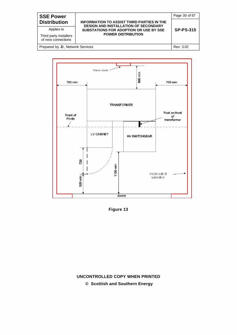
14.1 To allow adequate space around the plant for installation and maintenance, the plant shall be sited to comply with the dimensions shown in figure 13.
14.2 The alternative position of transformer and gear in relation to doors is shown in figure 14. When using this configuration consideration must be given for the need for personnel to escape easily from the substation.
15 FIRE RESISTANCE
15.1 SSEPD substations shall be designed with a minimum 1 hour fire resistance from a fire starting inside the enclosure. The ventilation of the enclosure does not generally need to comply with this requirement.
15.2 Where louvred doors or panels or other combustible media front onto a fire escape route or similar then a higher fire resistance may be required.
15.3 Resistance to fire from outside the enclosure will be a matter for Building Control or the Fire Authority depending on what the enclosure adjoins.
Page 30 of 67 SSE Power Distribution
Applies to
Third party installers of new connections
INFORMATION TO ASSIST THIRD PARTIES IN THE DESIGN AND INSTALLATION OF SECONDARY
SUBSTATIONS FOR ADOPTION OR USE BY SSE POWER DISTRIBUTION
SP-PS-315
Prepared by JB, Network Services Rev: 3.02
UNCONTROLLED COPY WHEN PRINTED
© Scottish and Southern Energy
Figure 13

Page 31 of 67 SSE Power Distribution
Applies to
Third party installers of new connections
INFORMATION TO ASSIST THIRD PARTIES IN THE DESIGN AND INSTALLATION OF SECONDARY
SUBSTATIONS FOR ADOPTION OR USE BY SSE POWER DISTRIBUTION
SP-PS-315
Prepared by JB, Network Services Rev: 3.02
UNCONTROLLED COPY WHEN PRINTED
© Scottish and Southern Energy
Figure 14
16 WEIGHT OF EQUIPMENT
16.1 The weight of a unit transformer, ring main equipment and low voltage cabinet shall be assumed to be 5.5 tonnes unless otherwise specified.
16.2 Padmount transformers and metering switchgear shall be assumed to be 1.0 tonnes unless otherwise specified.

Page 32 of 67 SSE Power Distribution
Applies to
Third party installers of new connections
INFORMATION TO ASSIST THIRD PARTIES IN THE DESIGN AND INSTALLATION OF SECONDARY
SUBSTATIONS FOR ADOPTION OR USE BY SSE POWER DISTRIBUTION
SP-PS-315
Prepared by JB, Network Services Rev: 3.02
UNCONTROLLED COPY WHEN PRINTED
© Scottish and Southern Energy
17 HEAT OUTPUT OF SWITCHGEAR
17.1 The heat output of switchgear can be ignored in the calculations for ventilation.
18 HEAT OUTPUT OF TRANSFORMER
18.1 The heat output of the transformer shall be assumed to be 15.8kW unless otherwise specified.
18.2 In substations containing more than one transformer in a common enclosure, the heat output shall be multiplied by the number of transformers and the ventilation increased accordingly.
19 SOUND OUTPUT OF TRANSFORMERS
19.1 The sound output of the transformer shall be assumed to be 69dBA per transformer unless otherwise specified.
19.2 The fundamental frequency is 100hz. For guidance the second and third harmonics are -10db and -12db below the fundamental.
19.3 On sites with multiple transformers in a common enclosure the effects of beating may need to be taken into consideration.
19.4 Note, transformer noise can also be transmitted, by vibration, through foundations. This can be mitigated by use of rubber, anti-vibration pads, or other such measure.
20 JOINT USER SUBSTATIONS
20.1 The following are specific requirements for joint user substations where SSEPD either owns or will adopt the high voltage switchgear and metering unit. Foundations are shown in figure 15. The cable trenches can be omitted and replaced by a fully excavatable area (with the exception of the plinth) which shall be sand filled and covered with a minimum of 150mm of stone chippings or course gravel once the electrical works have been completed
20.2 Ventilation is not required where the substation solely houses SSEPD switches and metering units unless otherwise specified. A single 13A power socket shall be provided.
20.3 The SSEPD owned plant can be accommodated in the same substation room as the customer’s equipment (i.e. no requirement for a dividing wall) provided that the customer’s high voltage and low voltage equipment is locked to prevent inadvertent operation (SSEPD equipment will always be

Page 33 of 67 SSE Power Distribution
Applies to
Third party installers of new connections
INFORMATION TO ASSIST THIRD PARTIES IN THE DESIGN AND INSTALLATION OF SECONDARY
SUBSTATIONS FOR ADOPTION OR USE BY SSE POWER DISTRIBUTION
SP-PS-315
Prepared by JB, Network Services Rev: 3.02
UNCONTROLLED COPY WHEN PRINTED
© Scottish and Southern Energy
locked).
20.4 All SSEPD owned equipment within a joint user substation will be fitted with a ‘Property Label as shown in figure16. In addition in ‘In case of Emergency’ phone number appropriate to the SSEPD licence area will also be fitted to SSEPD switchgear (provided by SSEPD) figure17.
20.5 Where joint user equipment and SSEPD equipment are in a common enclosure the joint user equipment will also be fitted with a property notice (by the joint user) distinctively designed differently from the SSEPD property label. Also the main access door will be fitted with SSEPD danger and ownership labels (provided by SSEPD) as shown in figure 18 and, similar labelling must be installed by the Joint User. Where the equipment is housed in separate, isolated, compartments then the entrance door to the compartment housing the SSEPD equipment will only be labelled with SSEPD danger and ownership labels.
20.6 SSEPD are not responsible for the upkeep or maintenance of the joint user substation or joint user switchgear. Obligations under the Electricity Safety, Quality and Continuity Regulations may mean that SSEPD has to carry out safety works in relation to the security of the enclosure. Where reasonably practical SSEPD will notify the Joint User requesting them to carry out the remedial work. Where this is not actioned with due diligence or such work requires an immediate response SSEPD reserve the right to pass on consequential costs to the Joint User.

Page 34 of 67 SSE Power Distribution
Applies to
Third party installers of new connections
INFORMATION TO ASSIST THIRD PARTIES IN THE DESIGN AND INSTALLATION OF SECONDARY
SUBSTATIONS FOR ADOPTION OR USE BY SSE POWER DISTRIBUTION
SP-PS-315
Prepared by JB, Network Services Rev: 3.02
UNCONTROLLED COPY WHEN PRINTED
© Scottish and Southern Energy
Figure 15

Page 35 of 67 SSE Power Distribution
Applies to
Third party installers of new connections
INFORMATION TO ASSIST THIRD PARTIES IN THE DESIGN AND INSTALLATION OF SECONDARY
SUBSTATIONS FOR ADOPTION OR USE BY SSE POWER DISTRIBUTION
SP-PS-315
Prepared by JB, Network Services Rev: 3.02
UNCONTROLLED COPY WHEN PRINTED
© Scottish and Southern Energy
Figure 16
Southern Electric Licence Area North of Scotland Hydro Electric
Licence Area
Figure 17

Page 36 of 67 SSE Power Distribution
Applies to
Third party installers of new connections
INFORMATION TO ASSIST THIRD PARTIES IN THE DESIGN AND INSTALLATION OF SECONDARY
SUBSTATIONS FOR ADOPTION OR USE BY SSE POWER DISTRIBUTION
SP-PS-315
Prepared by JB, Network Services Rev: 3.02
UNCONTROLLED COPY WHEN PRINTED
© Scottish and Southern Energy
Figure 18
Page 37 of 67 SSE Power Distribution
Applies to
Third party installers of new connections
INFORMATION TO ASSIST THIRD PARTIES IN THE DESIGN AND INSTALLATION OF SECONDARY
SUBSTATIONS FOR ADOPTION OR USE BY SSE POWER DISTRIBUTION
SP-PS-315
Prepared by JB, Network Services Rev: 3.02
UNCONTROLLED COPY WHEN PRINTED
© Scottish and Southern Energy
20.7 SSEPD equipment will be supplied with an electrical trip coil which can be used by the joint user to install an emergency trip. At least one emergency trip switch shall be installed with minimum rating of 3A @125Vac. Further trips can be added in parallel if required by the customer. The type of switch used shall be specified by the customer, but does not need approval by SSEPD. For guidance, internal switches can be of the push to make rotate to reset type. External switches can be of the break glass type. It is suggested that the colour is not red to prevent it being mistaken for a fire alarm.
20.8 Cable trenches shall have a minimum open width of 0.5m and depth of 0.7m and be covered with a metal grillage which is either located in rebates or angle iron. The grillage shall be prevented from touching the High voltage or metering cables Cable trenches shall not pass under the switchgear.
20.9 Access and cables routes will be agreed with SSEPD and must be legally secured.
21 HIGH VOLTAGE METERING – JOINT USER SUBSTATION
21.1 Where a customer is metered at High Voltage, provision has to be made for both the customer and meter operator to have access to the meters.
21.2 The metering will be housed in the customer’s plant room where this either contains or abuts the room containing the SSEPD metering switchgear. Where the meter operator does not have or will not be provided with a key to the room containing the meters then a lockout box (containing a key) shall be installed adjacent to the access door.
21.3 Where the customer does not have a plant room or it is remote, then a meter cabinet shall be installed in the outside wall of the room containing the SSEPD metering switchgear. This cabinet shall be lockable and if the meter operator will not be provided with a key, a lockout box (containing a key) shall be provided.
22 HIGH VOLTAGE METERING – EMBEDDED NETWORKS
22.1 Where the enclosure is brick-built the metering will be housed in the SSEPD substation. Lockout boxes are not required.
22.2 Where the metering switchgear is housed in a GRP enclosure then a separate GRP kiosk, external to the GRP enclosure, shall be provided to house the metering.

Page 38 of 67 SSE Power Distribution
Applies to
Third party installers of new connections
INFORMATION TO ASSIST THIRD PARTIES IN THE DESIGN AND INSTALLATION OF SECONDARY
SUBSTATIONS FOR ADOPTION OR USE BY SSE POWER DISTRIBUTION
SP-PS-315
Prepared by JB, Network Services Rev: 3.02
UNCONTROLLED COPY WHEN PRINTED
© Scottish and Southern Energy
23 SUBSTATION DESIGN – GENERAL
23.1 With the exception of the GRP Enclosure and Padmount Transformer, all other designs shall be forwarded to the SSEPD Civil Engineering Section for comment prior to construction. This process will ensure that items such as clearances and ventilation etc. are correct before construction is started.
24 SWITCHGEAR
24.1 Approved HV switchgear shall be manufactured to ENA Technical Specification performance criteria but meets SSEPD power system interface requirements thus enabling cable, protection and operational arrangements to be adequately catered for.
25 SWITCHGEAR TYPES
25.1 SSEPD utilise the following types of HV Switchgear:
25.2 Oil-insulated Ring Main Equipment (RME) incorporating a fuse switch. RME with SF6 insulated ring switches and circuit breaker tee-off. RME with SF6 insulated ring switches and vacuum circuit breaker tee-off. RMEs will be required in either free standing or transformer mounted arrangements depending on the network design.
25.3 Non-extensible Oil Fused Switch units with fully rated feeder earth switch in free standing or transformer mounting arrangements.
25.4 Free standing non-extensible SF6 or Vacuum circuit breakers complete with fully rated earth switches and test facilities on the incoming and outgoing side.
25.5 Air insulated fused-end box suitable for transformer mounting and complete with air-insulated fuses and cable disconnecting facilities.
25.6 SF6 circuit breaker assembly suitable for transformer mounting and complete with fully rated earth switch on the incoming side.
25.7 Oil Filled Ring Main Equipment fitted with oil filled metering unit.
25.8 SF6 Filled or Vacuum Ring Main Equipment fitted with air insulated metering unit.
25.9 Extensible SF6 filled switches and circuit breakers forming composite switchboards.
25.10 RME as previously specified fitted with automated ring main switches.

Page 39 of 67 SSE Power Distribution
Applies to
Third party installers of new connections
INFORMATION TO ASSIST THIRD PARTIES IN THE DESIGN AND INSTALLATION OF SECONDARY
SUBSTATIONS FOR ADOPTION OR USE BY SSE POWER DISTRIBUTION
SP-PS-315
Prepared by JB, Network Services Rev: 3.02
UNCONTROLLED COPY WHEN PRINTED
© Scottish and Southern Energy
25.11 Fault Passage Indicators shall be provided where network design arrangements so demand, generally restricted to automated switchgear.
26 APPROVED SWITCHGEAR MANUFACTURERS AND PRODUCT TYPES
26.1 SSEPD have approved the following manufacturers of HV switchgear systems and manufacturer product types.
Manufacturer Type
Schneider Electric, Leeds Ringmaster Range of Products
Metering Units
Webster Wilkinson HV Fused End Box
Lucy SF6 or Oil Ring Main Equipment
Metering Units
27 GROUND MOUNTED SECONDARY DISTRIBUTION TRANSFORMERS
27.1 SSEPD utilise a standardised range of ground mounted secondary distribution transformers (both unit and cable connected types) designed to ENA TS 35-1 but meeting SSEPD power system interface requirements. In this respect both free standing and unit style transformers are in common use although where ‘factory built substations’ are concerned this approach may be modified provided the performance requirements are met.
27.2 The SSEPD preference is for oil (or Midal) insulated, unit type, transformers. SSEPD do permit the use of resin filled or dry type transformers without the express approval of the SSEPD Planning Engineer. Such approval will be subject to the agreement regarding the provision of spares or temporary replacement transformers. SSEPD only holds spare oil filled transformers and these will be used to replace a failed dry or resin filled type, on a temporary basis, until an replacement can be manufactured. Where the fire resistance must be maintained at all times then either a spare transformer will be available on site or redundancy built into the network to allow for a transformer failure. The precise method must be agreed with the SSEPD Planning Engineer.
27.3 The current specification calls for radiators and tanks, of oil filled transformers, to be galvanised prior to painting.
Page 40 of 67 SSE Power Distribution
Applies to
Third party installers of new connections
INFORMATION TO ASSIST THIRD PARTIES IN THE DESIGN AND INSTALLATION OF SECONDARY
SUBSTATIONS FOR ADOPTION OR USE BY SSE POWER DISTRIBUTION
SP-PS-315
Prepared by JB, Network Services Rev: 3.02
UNCONTROLLED COPY WHEN PRINTED
© Scottish and Southern Energy
27.4 Standard transformers will be designed to have an impedance of 4.75% (5% on 1500kVA transformers) on rating at nominal tap, will be connected Dyn 11, will have a ratio 11000/433/250V with a tapping range of ± 5% in 2.5% taps. The transformer will have a Basic Impulse Level (BIL) of 75kV.
27.5 Transformers for use with a system voltage of 6.6kV shall be dual rated to be capable of working on both a 6.6kV and 11kV system (contact SSEPD for further advice).
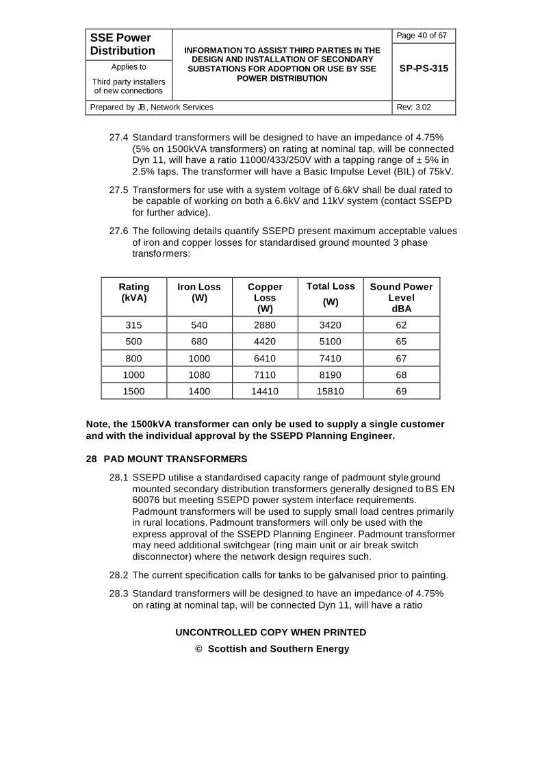
27.6 The following details quantify SSEPD present maximum acceptable values of iron and copper losses for standardised ground mounted 3 phase transformers:
Rating (kVA)
Iron Loss (W)
Copper Loss (W)
Total Loss
(W)
Sound Power Level dBA
315 540 2880 3420 62
500 680 4420 5100 65
800 1000 6410 7410 67
1000 1080 7110 8190 68
1500 1400 14410 15810 69
Note, the 1500kVA transformer can only be used to supply a single customer and with the individual approval by the SSEPD Planning Engineer.
28 PAD MOUNT TRANSFORMERS
28.1 SSEPD utilise a standardised capacity range of padmount style ground mounted secondary distribution transformers generally designed to BS EN 60076 but meeting SSEPD power system interface requirements. Padmount transformers will be used to supply small load centres primarily in rural locations. Padmount transformers will only be used with the express approval of the SSEPD Planning Engineer. Padmount transformer may need additional switchgear (ring main unit or air break switch disconnector) where the network design requires such.
28.2 The current specification calls for tanks to be galvanised prior to painting.
28.3 Standard transformers will be designed to have an impedance of 4.75% on rating at nominal tap, will be connected Dyn 11, will have a ratio

Page 41 of 67 SSE Power Distribution
Applies to
Third party installers of new connections
INFORMATION TO ASSIST THIRD PARTIES IN THE DESIGN AND INSTALLATION OF SECONDARY
SUBSTATIONS FOR ADOPTION OR USE BY SSE POWER DISTRIBUTION
SP-PS-315
Prepared by JB, Network Services Rev: 3.02
UNCONTROLLED COPY WHEN PRINTED
© Scottish and Southern Energy
11000/433/250V with a tapping range of ± 5% in 2.5% taps. The transformer will have a Basic Impulse Level (BIL) of 75kV.
28.4 Transformers for use with a system voltage of 6.6kV shall be dual rated to be capable of working on both a 6.6kV and 11kV system (contact SSEPD for further advice).
28.5 Padmount transformers are supplied with an HV fused end box and are not provided with any switchgear. Where installed on an underground network they may be teed into a network providing there are no other teed transformers in the section. Where RME is required then consideration must be given to using a 315kVA unit substation instead of a free standing RME and padmount transformer. Where they are to be installed on an overhead line then an air break switch disconnector shall be installed to provide isolation.

Page 42 of 67 SSE Power Distribution
Applies to
Third party installers of new connections
INFORMATION TO ASSIST THIRD PARTIES IN THE DESIGN AND INSTALLATION OF SECONDARY
SUBSTATIONS FOR ADOPTION OR USE BY SSE POWER DISTRIBUTION
SP-PS-315
Prepared by JB, Network Services Rev: 3.02
UNCONTROLLED COPY WHEN PRINTED
© Scottish and Southern Energy
Voltage Ratio Phase Rating
kVA
Impedance
%
Sound Power Level
dBA
6600/250 or
11000/250
(3 wire system)
Single 50 4.5 51
6600/250 or
11000/250
(3 wire system)
Single 100 4.5 56
6600/433-250 or
11000/433-250 Three 50 4.5 52
6600/433-250 or
11000/433-250 Three 100 4.75 56
6600/433-250 or
11000/433-250 Three 200 4.75 59
29 APPROVED TRANSFORMER MANUFACTURERS
29.1 SSEPD have approved the following manufacturers for the supply of ground mounted secondary distribution transformers..
Manufacturer Type
Efacec, Portugal Unit and Cable Connected
Schneider Unit and Cable Connected
ABB Ireland Padmount Transformers

Page 43 of 67 SSE Power Distribution
Applies to
Third party installers of new connections
INFORMATION TO ASSIST THIRD PARTIES IN THE DESIGN AND INSTALLATION OF SECONDARY
SUBSTATIONS FOR ADOPTION OR USE BY SSE POWER DISTRIBUTION
SP-PS-315
Prepared by JB, Network Services Rev: 3.02
UNCONTROLLED COPY WHEN PRINTED
© Scottish and Southern Energy
30 TRANSFORMER MOUNTED AND FREE STANDING LV CABINETS AND PILLARS
30.1 SSEPD utilise a standard range of LV Distribution Cabinets and Pillars, built to comply with Energy Networks Association Technical Specification 37-2.
30.2 The following list details some of the standardised cabinet and pillar layouts i.
Incomer Feeder Ways Application
800A or 1600A
4 or 5 x 630A Housing
1600A 2 or 3 x 630A plus 1 x 800A
Industrial/Commercial
1600A 1 or 2 x 6300A plus 1 x 1600A
Industrial/Commercial
31 APPROVED LV CABINET AND PILLAR MANUFACTURERS
31.1 SSEPD has approved the following manufacturers for the supply of LV cabinets and pillars.
Manufacturer Type
W Lucy, Thame Pillars, Cabinets and Wall Boards
32 PROVISION OF EQUIPMENT OTHER THAN ON CURRENT SSEPD CONTRACT
32.1 SSEPD prefer to use plant that is currently on its term contract. This ensures our staff are operationally familiar with it, we carry spares, we are sure it is fit for purpose and important ancillary equipment is available for our use (such as earthing trucks etc.). If other manufacturers, or other types of, equipment is proposed we require that
Page 44 of 67 SSE Power Distribution
Applies to
Third party installers of new connections
INFORMATION TO ASSIST THIRD PARTIES IN THE DESIGN AND INSTALLATION OF SECONDARY
SUBSTATIONS FOR ADOPTION OR USE BY SSE POWER DISTRIBUTION
SP-PS-315
Prepared by JB, Network Services Rev: 3.02
UNCONTROLLED COPY WHEN PRINTED
© Scottish and Southern Energy
32.1.1 It is fit for purpose. Generally this means complying with Energy Networks Association (ENA) Technical Specifications and usually passed ENA assessment.
32.1.2 Adequate training is provided for SSEPD operational staff likely to use the equipment.
32.1.3 Installation, Operation and Maintenance Manuals are provided for SSEPD use and short-form manuals are provided giving basic operational requirements.
32.1.4 Minimum quantities of spares are provided or are available on site for likely failure modes of the equipment. For certain types of plant this may involve a replacement item rather than parts.
32.1.5 It is important the customer does not order the equipment until written confirmation of its acceptability to SSEPD has been received.
32.2 Each proposal is considered on its individual merits for suitability of connection to the SSEPD Network. This may result in rejection of the proposal should any of the above not be complied with.
33 FUSING POLICY FOR SUBSTATIONS
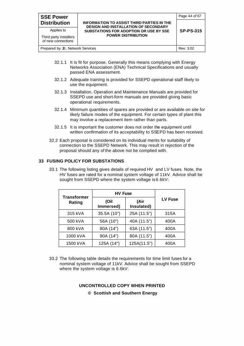
33.1 The following listing gives details of required HV and LV fuses. Note, the HV fuses are rated for a nominal system voltage of 11kV. Advice shall be sought from SSEPD where the system voltage is 6.6kV:
HV Fuse Transformer
Rating (Oil Immersed)
(Air Insulated)
LV Fuse
315 kVA 35.5A (10”) 25A (11.5”) 315A
500 kVA 56A (10”) 40A (11.5”) 400A
800 kVA 80A (14”) 63A (11.5”) 400A
1000 kVA 90A (14”) 80A (11.5”) 400A
1500 kVA 125A (14") 125A(11.5") 400A
33.2 The following table details the requirements for time limit fuses for a nominal system voltage of 11kV. Advice shall be sought from SSEPD where the system voltage is 6.6kV:

Page 45 of 67 SSE Power Distribution
Applies to
Third party installers of new connections
INFORMATION TO ASSIST THIRD PARTIES IN THE DESIGN AND INSTALLATION OF SECONDARY
SUBSTATIONS FOR ADOPTION OR USE BY SSE POWER DISTRIBUTION
SP-PS-315
Prepared by JB, Network Services Rev: 3.02
UNCONTROLLED COPY WHEN PRINTED
© Scottish and Southern Energy
Current Transformer
Ratio
Total Transformer Capacity
Time Limit Fuse Rating
(A)
50/5 315 kVA 5
50/5 500 kVA 10
50/5 800 kVA 12.5
50/5 1000 kVA 15
100/5 800kVA 7.5
100/5 1000kVA 10
100/5 1500 kVA 12.5
Page 46 of 67 SSE Power Distribution
Applies to
Third party installers of new connections
INFORMATION TO ASSIST THIRD PARTIES IN THE DESIGN AND INSTALLATION OF SECONDARY
SUBSTATIONS FOR ADOPTION OR USE BY SSE POWER DISTRIBUTION
SP-PS-315
Prepared by JB, Network Services Rev: 3.02
UNCONTROLLED COPY WHEN PRINTED
© Scottish and Southern Energy
34 EARTHING
34.1 For specific guidance on the requirements for earthing and bonding of cables and overhead lines refer to SSEPD document SP-PS-312, Bonding and Earthing During the Installation of New Connections
34.2 Earth electrodes are required to prevent undesirable potential rises occurring on substation equipment and be capable of passing earth fault currents of up to 6,000 amps for 3 seconds and the resistance of the earth return path must be low enough to ensure the operation of the source circuit breaker protection.
34.3 Where the overall earth resistance is greater than 1Ω the LV neutral/HV steelwork earth must be segregated usually by removal of a commoning link in the cabinet or pillar.
34.4 Where substations are located within a steel framed building or where lightning protection is installed and the LV neutral/HV steelwork has to be segregated SSEPD shall be contacted for advice regarding the earthing requirement.
34.5 The earth resistance of each substation must be checked with an earth impedance tester. The results shall be submitted with the handover documents for the site. The maximum acceptable value for the LV neutral earth is 40Ω and 50Ω for the HV steelwork earth.
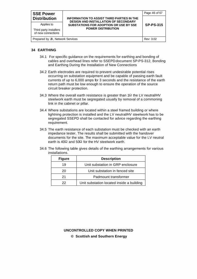
34.6 The following table gives details of the earthing arrangements for various installations.
Figure Description
19 Unit substation in GRP enclosure
20 Unit substation in fenced site
21 Padmount transformer
22 Unit substation located inside a building

Page 47 of 67 SSE Power Distribution
Applies to
Third party installers of new connections
INFORMATION TO ASSIST THIRD PARTIES IN THE DESIGN AND INSTALLATION OF SECONDARY
SUBSTATIONS FOR ADOPTION OR USE BY SSE POWER DISTRIBUTION
SP-PS-315
Prepared by JB, Network Services Rev: 3.02
UNCONTROLLED COPY WHEN PRINTED
© Scottish and Southern Energy
Figure 19

Page 48 of 67 SSE Power Distribution
Applies to
Third party installers of new connections
INFORMATION TO ASSIST THIRD PARTIES IN THE DESIGN AND INSTALLATION OF SECONDARY
SUBSTATIONS FOR ADOPTION OR USE BY SSE POWER DISTRIBUTION
SP-PS-315
Prepared by JB, Network Services Rev: 3.02
UNCONTROLLED COPY WHEN PRINTED
© Scottish and Southern Energy
Figure 20

Page 49 of 67 SSE Power Distribution
Applies to
Third party installers of new connections
INFORMATION TO ASSIST THIRD PARTIES IN THE DESIGN AND INSTALLATION OF SECONDARY
SUBSTATIONS FOR ADOPTION OR USE BY SSE POWER DISTRIBUTION
SP-PS-315
Prepared by JB, Network Services Rev: 3.02
UNCONTROLLED COPY WHEN PRINTED
© Scottish and Southern Energy
Figure 21

Page 50 of 67 SSE Power Distribution
Applies to
Third party installers of new connections
INFORMATION TO ASSIST THIRD PARTIES IN THE DESIGN AND INSTALLATION OF SECONDARY
SUBSTATIONS FOR ADOPTION OR USE BY SSE POWER DISTRIBUTION
SP-PS-315
Prepared by JB, Network Services Rev: 3.02
UNCONTROLLED COPY WHEN PRINTED
© Scottish and Southern Energy
Figure 22
Page 51 of 67 SSE Power Distribution
Applies to
Third party installers of new connections
INFORMATION TO ASSIST THIRD PARTIES IN THE DESIGN AND INSTALLATION OF SECONDARY
SUBSTATIONS FOR ADOPTION OR USE BY SSE POWER DISTRIBUTION
SP-PS-315
Prepared by JB, Network Services Rev: 3.02
UNCONTROLLED COPY WHEN PRINTED
© Scottish and Southern Energy
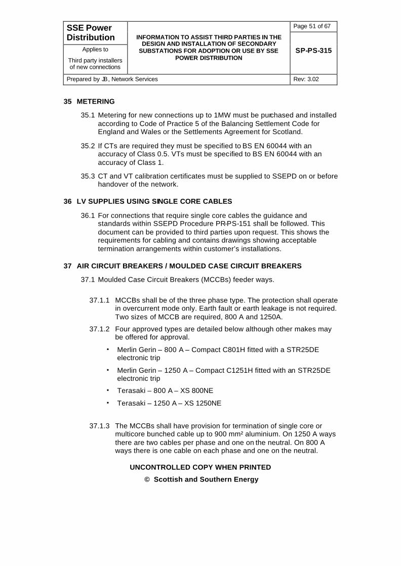
35 METERING
35.1 Metering for new connections up to 1MW must be purchased and installed according to Code of Practice 5 of the Balancing Settlement Code for England and Wales or the Settlements Agreement for Scotland.
35.2 If CTs are required they must be specified to BS EN 60044 with an accuracy of Class 0.5. VTs must be specified to BS EN 60044 with an accuracy of Class 1.
35.3 CT and VT calibration certificates must be supplied to SSEPD on or before handover of the network.
36 LV SUPPLIES USING SINGLE CORE CABLES
36.1 For connections that require single core cables the guidance and standards within SSEPD Procedure PR-PS-151 shall be followed. This document can be provided to third parties upon request. This shows the requirements for cabling and contains drawings showing acceptable termination arrangements within customer’s installations.
37 AIR CIRCUIT BREAKERS / MOULDED CASE CIRCUIT BREAKERS
37.1 Moulded Case Circuit Breakers (MCCBs) feeder ways.
37.1.1 MCCBs shall be of the three phase type. The protection shall operate in overcurrent mode only. Earth fault or earth leakage is not required. Two sizes of MCCB are required, 800 A and 1250A.
37.1.2 Four approved types are detailed below although other makes may be offered for approval.
• Merlin Gerin – 800 A – Compact C801H fitted with a STR25DE electronic trip
• Merlin Gerin – 1250 A – Compact C1251H fitted with an STR25DE electronic trip
• Terasaki – 800 A – XS 800NE
• Terasaki – 1250 A – XS 1250NE
37.1.3 The MCCBs shall have provision for termination of single core or multicore bunched cable up to 900 mm² aluminium. On 1250 A ways there are two cables per phase and one on the neutral. On 800 A ways there is one cable on each phase and one on the neutral.
Page 52 of 67 SSE Power Distribution
Applies to
Third party installers of new connections
INFORMATION TO ASSIST THIRD PARTIES IN THE DESIGN AND INSTALLATION OF SECONDARY
SUBSTATIONS FOR ADOPTION OR USE BY SSE POWER DISTRIBUTION
SP-PS-315
Prepared by JB, Network Services Rev: 3.02
UNCONTROLLED COPY WHEN PRINTED
© Scottish and Southern Energy
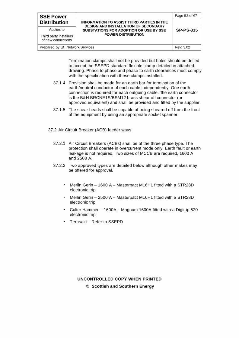
Termination clamps shall not be provided but holes should be drilled to accept the SSEPD standard flexible clamp detailed in attached drawing. Phase to phase and phase to earth clearances must comply with the specification with these clamps installed.
37.1.4 Provision shall be made for an earth bar for termination of the earth/neutral conductor of each cable independently. One earth connection is required for each outgoing cable. The earth connector is the B&H BRCNE1S/BSM12 brass shear off connector (or approved equivalent) and shall be provided and fitted by the supplier.
37.1.5 The shear heads shall be capable of being sheared off from the front of the equipment by using an appropriate socket spanner.
37.2 Air Circuit Breaker (ACB) feeder ways
37.2.1 Air Circuit Breakers (ACBs) shall be of the three phase type. The protection shall operate in overcurrent mode only. Earth fault or earth leakage is not required. Two sizes of MCCB are required, 1600 A and 2500 A.
37.2.2 Two approved types are detailed below although other makes may be offered for approval.
• Merlin Gerin – 1600 A – Masterpact M16H1 fitted with a STR28D electronic trip
• Merlin Gerin – 2500 A – Masterpact M16H1 fitted with a STR28D electronic trip
• Culter Hammer – 1600A – Magnum 1600A fitted with a Digitrip 520 electronic trip
• Terasaki – Refer to SSEPD

Page 53 of 67 SSE Power Distribution
Applies to
Third party installers of new connections
INFORMATION TO ASSIST THIRD PARTIES IN THE DESIGN AND INSTALLATION OF SECONDARY
SUBSTATIONS FOR ADOPTION OR USE BY SSE POWER DISTRIBUTION
SP-PS-315
Prepared by JB, Network Services Rev: 3.02
UNCONTROLLED COPY WHEN PRINTED
© Scottish and Southern Energy
37.2.3 The ACBs shall have provision for termination of single core or multicore bunched cable up to 900 mm² aluminium. On 1600 A and 2500 A ways there are three cables per phase and two on the neutral. Termination clamps shall not be provided but holes should be drilled to accept the SSEPD standard flexible clamp detailed in figure 23. Phase to phase and phase to earth clearances must comply with the specification with these clamps installed.
37.2.4 Provision shall be made for an earth bar for termination of the earth conductor of each cable independently. One earth connection is required for each outgoing cable.
37.2.5 The earth connector is the B&H BTCNE1S/BSM12 brass shear off connector (or approved equivalent) and shall be provided by the supplier. The shear heads shall be capable of being sheared off from the front of the equipment by using an appropriate socket spanner.
38 HANDING OVER ARRANGEMENTS
38.1 A certificate of commissioning and handing over shall be provided and accepted by a representative of SSEPD. SSEPD document FO-PS-110 shall be used for this purpose.
38.2 Please note that where a substation building to be adopted by SSEPD it is a requirement that the building be accepted by the SSEPD Civil Engineering Section and any remedial work required shall be carried out prior to it final acceptance and energisation.
38.3 For other installations the substation building will be checked by SSEPD Civil Engineering Section to ensure suitability of plinths, cable trenches and ventilation. Any remedial work required shall be carried out prior to its final acceptance and energisation.

Page 54 of 67 SSE Power Distribution
Applies to
Third party installers of new connections
INFORMATION TO ASSIST THIRD PARTIES IN THE DESIGN AND INSTALLATION OF SECONDARY
SUBSTATIONS FOR ADOPTION OR USE BY SSE POWER DISTRIBUTION
SP-PS-315
Prepared by JB, Network Services Rev: 3.02
UNCONTROLLED COPY WHEN PRINTED
© Scottish and Southern Energy
Figure 23

Page 55 of 67 SSE Power Distribution
Applies to
Third party installers of new connections
INFORMATION TO ASSIST THIRD PARTIES IN THE DESIGN AND INSTALLATION OF SECONDARY
SUBSTATIONS FOR ADOPTION OR USE BY SSE POWER DISTRIBUTION
SP-PS-315
Prepared by JB, Network Services Rev: 3.02
UNCONTROLLED COPY WHEN PRINTED
© Scottish and Southern Energy
39 MULTIPLE OCCUPANCY DOMESTIC BUILDINGS AND COMPLEXES
39.1 The installation for rising and/or lateral services in multiple occupancy domestic buildings and complexes is using SNE cables and SNE (TN-S) earthing. This will be applied whether or not the building is steel framed. Incoming and rising mains cables will be terminated in multiple service distribution boards (MSDBs). The approved supplier is shown below:
Manufacturer Type
W Lucy, Thame J1, J2 type MSDBs
39.2 The ownership and responsibility of rising and/or lateral services in buildings will determine the design. The services may be owned by SSE Power Distribution or the customer.
39.3 Rising mains will be installed using Multiple Service Distribution Boards (MSDBs). Up to three MSDBs can be connected in series. The arrangement is shown in figures 24 to 28. Note the incoming LSOH cable shown may not be necessary in every case. Specific details are given later.
39.4 The rising mains between MSDBs shall be 185mm² LSOH, 4 core Wavecon cable. Rising and lateral services shall be 35mm² LSOH split concentric cable.
39.5 If the incoming main cable is being terminated in an LV cabinet it is preferable to convert the cabinet to SNE earthing and lay a 4 core wavecon cable. Where this is not possible then a 3 core wavecon cable shall be laid. Either a 185mm² or 300mm² can be used depending on the load required.
39.6 Where the incoming cable is to be breeched onto an existing SNE main then either a 185mm² or 300mm², 4 core, incoming mains cable is required.
39.7 Where the incoming cable is to be breeched onto an existing CNE main then either a 185mm² or 300mm², 3 core, incoming mains cable is required.

Page 56 of 67 SSE Power Distribution
Applies to
Third party installers of new connections
INFORMATION TO ASSIST THIRD PARTIES IN THE DESIGN AND INSTALLATION OF SECONDARY
SUBSTATIONS FOR ADOPTION OR USE BY SSE POWER DISTRIBUTION
SP-PS-315
Prepared by JB, Network Services Rev: 3.02
UNCONTROLLED COPY WHEN PRINTED
© Scottish and Southern Energy
39.8 The incoming cable must be protected against fire subject to the following:
39.8.1 Where the cable is laid in duct and only 1m is exposed from the end of the duct to the incoming MSDB then no protection is required.
39.8.2 Where the exposed cable (either from the end of duct or installed in trays) is between 1m and 10m the cable shall be wrapped in 3M No.77 Arc Protection Tape available from Sicame Electrical. The tape shall be installed with a 50% overlap and secured using pvc tape.
39.8.3 Where the exposed cable (either from the end of duct or installed in trays) is greater than 10m then LSOH Wavecon cable shall be installed and jointed outside the building onto the standard Wavecon cable.
39.9 Cabling installed direct from substation (Figure 24)
39.9.1 Where incoming cables are installed direct from a substation the complete installation shall be SNE and 4 core mains cables used throughout.
39.9.2 The LV cabinet shall be converted to take a 4 core, Wavecon cable.
39.9.3 The 4 core Wavecon cable shall be terminated in an MSDB.
39.9.4 The link between the neutral block and the earth block of the MSDB must be removed.
39.9.5 Rising mains cables shall be 4 core, LSOH cable terminating in MSDBs. The links in these units shall be removed.
39.10 Cabling installed from an existing CNE main (figure 25)
39.10.1 Where cables are installed direct from an existing CNE main only the service termination and internal services will be SNE.
39.10.2 A 3 core Wavecon cable shall be laid and jointed onto the existing CNE main .
39.10.3 The 3 core Wavecon cable shall be terminated in an multiple service distribution board (MSDB).
39.10.4 An earth electrode, with an earth resistance of not more than 8 ohms shall be connected to the earth terminal of the MSDB using 16mm², pvc covered, copper cable.
39.10.5 The link between the neutral block and the earth block of the MSDB must be left in place.
39.10.6 Rising mains cables shall be 4 core, LSOH cable terminating in MSDBs. With the exception of the incoming MSDB the links in these other units
Page 57 of 67 SSE Power Distribution
Applies to
Third party installers of new connections
INFORMATION TO ASSIST THIRD PARTIES IN THE DESIGN AND INSTALLATION OF SECONDARY
SUBSTATIONS FOR ADOPTION OR USE BY SSE POWER DISTRIBUTION
SP-PS-315
Prepared by JB, Network Services Rev: 3.02
UNCONTROLLED COPY WHEN PRINTED
© Scottish and Southern Energy
must be removed.
39.11 Cabling installed from an existing SNE main (Figure 26)
39.11.1 Where cables are installed direct from an existing SNE main the complete installation shall be SNE.
39.11.2 A 4 core Wavecon cable shall be laid and jointed onto the existing SNE main .
39.11.3 The 4 core Wavecon cable shall be terminated in an multiple service distribution board (MSDB).
39.11.4 The link between the neutral block and the earth block of the MSDB must be removed.
39.11.5 Rising mains cables shall be 4 core, LSOH cable terminating in MSDBs. The links in these units must be removed.
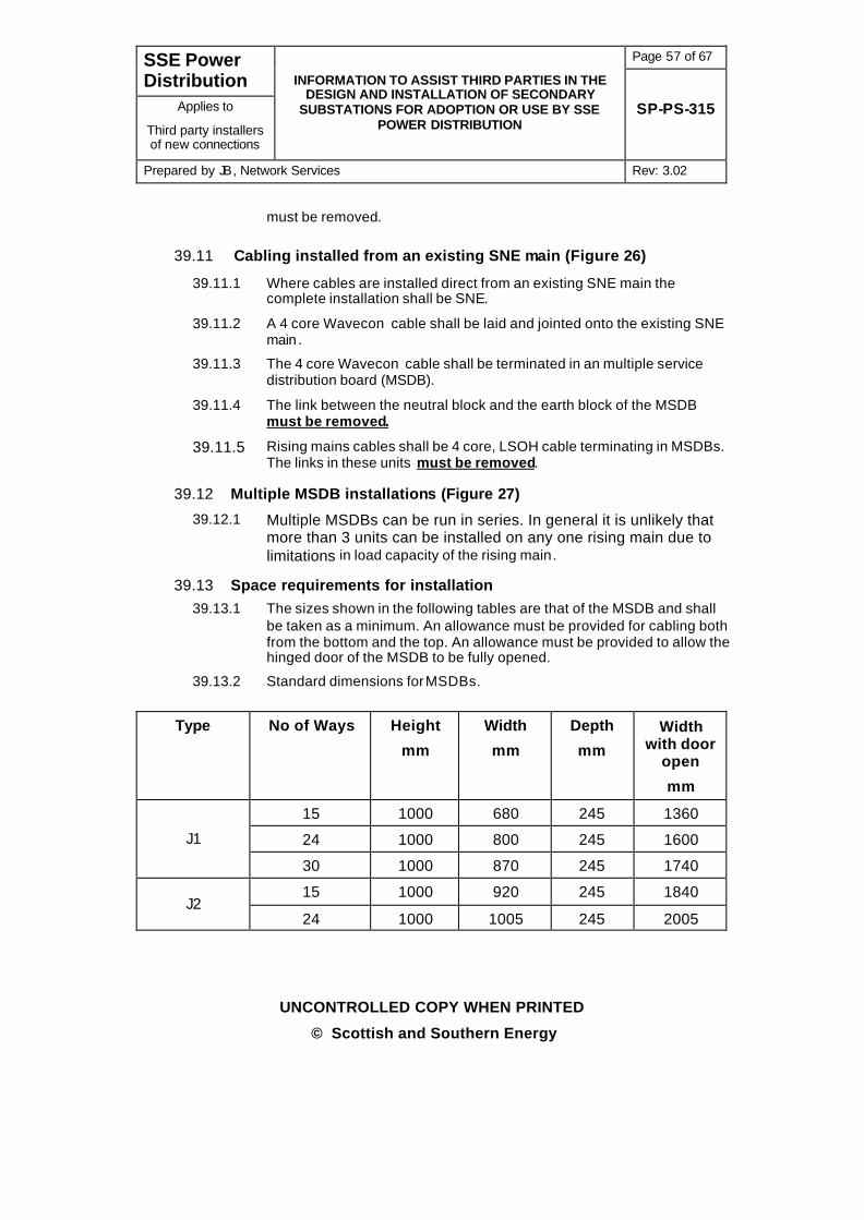
39.12 Multiple MSDB installations (Figure 27)
39.12.1 Multiple MSDBs can be run in series. In general it is unlikely that more than 3 units can be installed on any one rising main due to limitations in load capacity of the rising main.
39.13 Space requirements for installation 39.13.1 The sizes shown in the following tables are that of the MSDB and shall
be taken as a minimum. An allowance must be provided for cabling both from the bottom and the top. An allowance must be provided to allow the hinged door of the MSDB to be fully opened.
39.13.2 Standard dimensions for MSDBs.
Type No of Ways Height
mm
Width
mm
Depth
mm
Width with door
open
mm
15 1000 680 245 1360
24 1000 800 245 1600 J1
30 1000 870 245 1740
15 1000 920 245 1840 J2
24 1000 1005 245 2005

Page 58 of 67 SSE Power Distribution
Applies to
Third party installers of new connections
INFORMATION TO ASSIST THIRD PARTIES IN THE DESIGN AND INSTALLATION OF SECONDARY
SUBSTATIONS FOR ADOPTION OR USE BY SSE POWER DISTRIBUTION
SP-PS-315
Prepared by JB, Network Services Rev: 3.02
UNCONTROLLED COPY WHEN PRINTED
© Scottish and Southern Energy
39.14 Single MSDB Installations (Figure 28) 39.14.1 Single J1 MSDBs can be installed where high load capacity is required.
39.15 Fusing of MSDBs 39.15.1 The table below shows the allowable fuse selection which suits most
installations. Where larger fuse sizes are required SSEPD Network Services shall be consulted.
Location Description Maximum Fuse Size
LV cabinet or pillar Size A 400A(500A note 1)
MSDB Size B 200A
MSDB Size C 315A
MSDB Size D 400A (note 2)
Note 1 where cable rating permits
Note 2 May not discriminate with LV cabinet fuse where this is 400A.

Page 59 of 67 SSE Power Distribution
Applies to
Third party installers of new connections
INFORMATION TO ASSIST THIRD PARTIES IN THE DESIGN AND INSTALLATION OF SECONDARY
SUBSTATIONS FOR ADOPTION OR USE BY SSE POWER DISTRIBUTION
SP-PS-315
Prepared by JB, Network Services Rev: 3.02
UNCONTROLLED COPY WHEN PRINTED
© Scottish and Southern Energy
Figure 24

Page 60 of 67 SSE Power Distribution
Applies to
Third party installers of new connections
INFORMATION TO ASSIST THIRD PARTIES IN THE DESIGN AND INSTALLATION OF SECONDARY
SUBSTATIONS FOR ADOPTION OR USE BY SSE POWER DISTRIBUTION
SP-PS-315
Prepared by JB, Network Services Rev: 3.02
UNCONTROLLED COPY WHEN PRINTED
© Scottish and Southern Energy
Figure 25

Page 61 of 67 SSE Power Distribution
Applies to
Third party installers of new connections
INFORMATION TO ASSIST THIRD PARTIES IN THE DESIGN AND INSTALLATION OF SECONDARY
SUBSTATIONS FOR ADOPTION OR USE BY SSE POWER DISTRIBUTION
SP-PS-315
Prepared by JB, Network Services Rev: 3.02
UNCONTROLLED COPY WHEN PRINTED
© Scottish and Southern Energy
Figure 26
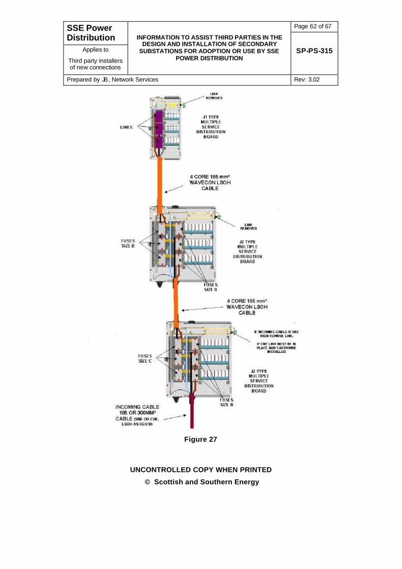
Page 62 of 67 SSE Power Distribution
Applies to
Third party installers of new connections
INFORMATION TO ASSIST THIRD PARTIES IN THE DESIGN AND INSTALLATION OF SECONDARY
SUBSTATIONS FOR ADOPTION OR USE BY SSE POWER DISTRIBUTION
SP-PS-315
Prepared by JB, Network Services Rev: 3.02
UNCONTROLLED COPY WHEN PRINTED
© Scottish and Southern Energy
Figure 27

Page 63 of 67 SSE Power Distribution
Applies to
Third party installers of new connections
INFORMATION TO ASSIST THIRD PARTIES IN THE DESIGN AND INSTALLATION OF SECONDARY
SUBSTATIONS FOR ADOPTION OR USE BY SSE POWER DISTRIBUTION
SP-PS-315
Prepared by JB, Network Services Rev: 3.02
UNCONTROLLED COPY WHEN PRINTED
© Scottish and Southern Energy
Figure 28
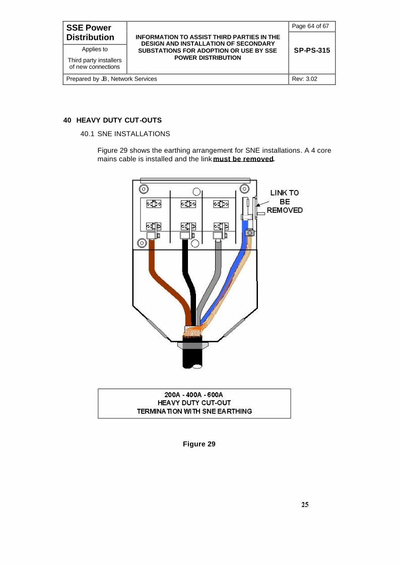
Page 64 of 67 SSE Power Distribution
Applies to
Third party installers of new connections
INFORMATION TO ASSIST THIRD PARTIES IN THE DESIGN AND INSTALLATION OF SECONDARY
SUBSTATIONS FOR ADOPTION OR USE BY SSE POWER DISTRIBUTION
SP-PS-315
Prepared by JB, Network Services Rev: 3.02
UNCONTROLLED COPY WHEN PRINTED
© Scottish and Southern Energy
40 HEAVY DUTY CUT-OUTS
40.1 SNE INSTALLATIONS Figure 29 shows the earthing arrangement for SNE installations. A 4 core mains cable is installed and the link must be removed.
Figure 29

Page 65 of 67 SSE Power Distribution
Applies to
Third party installers of new connections
INFORMATION TO ASSIST THIRD PARTIES IN THE DESIGN AND INSTALLATION OF SECONDARY
SUBSTATIONS FOR ADOPTION OR USE BY SSE POWER DISTRIBUTION
SP-PS-315
Prepared by JB, Network Services Rev: 3.02
UNCONTROLLED COPY WHEN PRINTED
© Scottish and Southern Energy
40.2 CNE INSTALLATIONS Figure 30 shows the earthing arrangement for CNE installations. A 3 core mains cable is installed and the link must be left in. An earth electrode, with an earth resistance of not more than 8 ohms shall be connected to the earth terminal of the cut-out using 16mm², pvc covered, copper cable.
Figure 30

Page 66 of 67 SSE Power Distribution
Applies to
Third party installers of new connections
INFORMATION TO ASSIST THIRD PARTIES IN THE DESIGN AND INSTALLATION OF SECONDARY
SUBSTATIONS FOR ADOPTION OR USE BY SSE POWER DISTRIBUTION
SP-PS-315
Prepared by JB, Network Services Rev: 3.02
UNCONTROLLED COPY WHEN PRINTED
© Scottish and Southern Energy
41 SPECIFICATION UPDATING – IMPORTANT REQUIREMENT
41.1 The above details represent SSEPD current design and preferred products. However, practise may from time to time be modified in the light of product development and the developer shall ensure that he has the latest edition of this specification which is available on the Scottish and Southern Energy web site.
42 ASSOCIATED DOCUMENTATION
Author’s note. Extracts from the following documents have being included in this specification
PR-PS-353 Safety, Ownership Signs and Fencing Requirements applicable to Substations
TG-PS-490 Technical Guidance for use in Selection of Standard Enclosures for New Secondary Sub-stations
TG-PS-073 Earthing of 11kV Installations
TG-PS-151 Fusing requirements for HV Ground Mounted Plant
SP-PS-340 Power Systems Requirement for Indoor Secondary Substation Site
SP-PS-240 Specification for the supply of pad mounted distribution transformers
SP-PS-142 Specification for the supply of oil immersed distribution transformers 315 – 1500kVA
SP-PS-031 LV Distribution Fuseboards, Cabinets and Pillars
SP-PS-312 Specification for Bonding and Earthing During the Installation of New Connections
TS 29 Outdoor Metalclad Secondary Distribution Switchgear
FO-PS-110 Declaration of Test Results for New Substation Equipment.
43 APPLICABLE STANDARDS
43.1 Third Parties must obtain copies of non SSEPD Standards from the issuing organisations at their own expense. These documents may be subject to copyright.
43.2 Third Parties will obtain copies of SSEPD Standards or other SSEPD documents from the SSEPD Power Systems Document Administrator, Inveralmond House, 200 Dunkeld Road, Perth PH1 3AQ.
Page 67 of 67 SSE Power Distribution
Applies to
Third party installers of new connections
INFORMATION TO ASSIST THIRD PARTIES IN THE DESIGN AND INSTALLATION OF SECONDARY
SUBSTATIONS FOR ADOPTION OR USE BY SSE POWER DISTRIBUTION
SP-PS-315
Prepared by JB, Network Services Rev: 3.02
UNCONTROLLED COPY WHEN PRINTED
© Scottish and Southern Energy
43.3 There will be a cost of £50 for each document requested to cover administration and copying costs.
Note SSEPD cannot provide copies of BS, IEC or ENA documents.