Embed Size (px)
Citation preview
Application
Electric Actuators Air Cylinders IO-Link Communication
IO-Link
Master
RoHSStep Motor Controller5 types of communication protocols
Both air and electric systems can be established under the same protocol.
Can be additionally installed in an existing network
Communication protocol
Slider type
LEF Series
Rod type
LEY/LEYG Series
PLC
Gripper
LEH Series
Slide table
LES/LESH Series
Rotary table
LER Series
Miniature type
LEPY/LEPS Series
Low-profi le slider type
LEM Series
Guide rod slider
LEL Series
<Applicable electric actuators>
EX260
NewNewNew NewNewNew
Electric Actuators Air Cylinders IO-Link Communication
IO-Link
Master
Both air and electric systems can be established under the same protocol.
Can be additionally installed in an existing network
PLC
EX260
INFORMATION
JXCE1/91/P1/D1/L1/M1 Series17-EU688-UK
PLC
Step no. defi ned operation: Operate using the preset step
data in the controller.
Numerical data defined operation: The actuator operates
using values such as position and speed from the PLC.
Numerical information, such as the current speed, current
position, and alarm codes, can be monitored on the PLC.
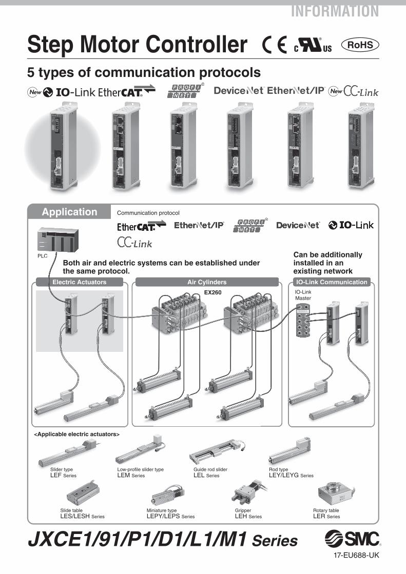
The data storage function eliminates the need for troublesome resetting
of step data and parameters when changing over the controller.
� Step data and parameters can be set from the master side.
Step data and parameters can be set or changed by
means of IO-Link communication.
� Data storage function
When the controller is changed, the parameters and
step data for the actuator are automatically set.∗1
�4-wire unshielded cables can be used.
Step Motor Controller
JXCL1
Two communication ports are provided.∗ For the DeviceNet™ type, transition wiring is possible using a branch connector.
∗ 1 to 1 in the case of IO-Link
IO-Link communication can be performed.
Two types of operation command Transition wiring of communication cables
Numerical monitoring available
Application
IO-Link is an open communication
interface technology between the
sensor/actuator and the I /O
terminal that is an international
standard, IEC61131-9.
PLC
IO-Link Master
IO-Link communication
Various fieldbusses
PC
∗1 The “basic parameter” and the “return to origin parameter” are
automatically set as the actuator parameters, and the 3 items of
data consisting of No. 0 to 2 are automatically set as the step data.
1
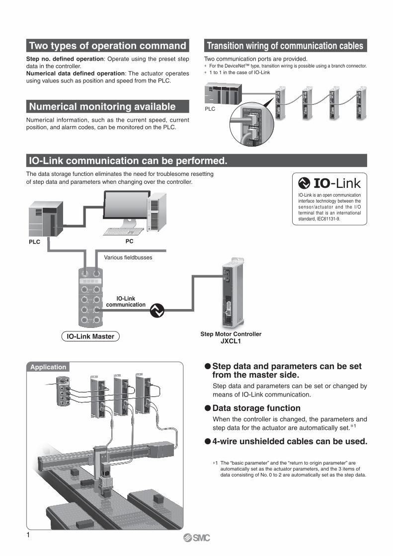
�Electric actuators
To SI
To ENC
To MOT
To PWR
LEY/LEYG Series
LEF Series
LES/LESH Series
LER Series
LEL Series
LEPY/LEPS Series
LEH Series
LEM Series
System Construction
�Actuator cable
LE-CP-�Robotic cable
LE-CP-�-S
Standard cable
JXC-CD-T
JXC-CD-SStraight type
T-branch type
PLC
Provided by customer
PLC
Provided by customer
PLC
Provided by customer
PLC
Provided by customer
Power supplyfor controller
24 VDC
Provided by customer
� Power supply plug
(Accessory)
�Teaching box
(With 3 m cable)LEC-T1-3EG�
Options
Communication cable�(3 m)
∗1 A conversion cable is also required for connecting the controller to the LEC-W2. (A conversion cable is not required for the JXC-W2.)
� Communication plugconnector for DeviceNet™ p. 7 p. 7
To SI
The conversion cable can be used for con-necting this controller to the optional teaching box [LEC-T1] offered with the LEC series.
JXC-CL-SStraight type
IO-Link master
Provided by customer
� Communication plugconnector for IO-Link
or
(A-mini B type)(0.8 m)
�USB cable
�Controller setting kit
Controller setting kit(A communication cable, USB cable, and controller setting software (CD-ROM) are included.)JXC-W2
� Conversion cable∗1
P5062-5(0.3 m)
PC
� Conversion cable
(Accessory)
p. 7
p. 7
p. 7p. 7
p. 7
2
Step Motor Controller JXCE1/91/P1/D1/L1/M1 Series
When selecting an electric actuator, refer to the model selection chart of each
actuator. Also, for the “Speed–Work Load” graph of the actuator, refer to the LEC
section on the model selection page of the electric actuators Web Catalogue.
Mounting
7 Screw mounting
8∗1 DIN rail
∗1 The DIN rail is not included. It must be
ordered separately.
(Refer to page 7.)
∗ Select “Nil” for anything other than JXCD1.
∗ Select “Nil” for anything other than JXCD1.
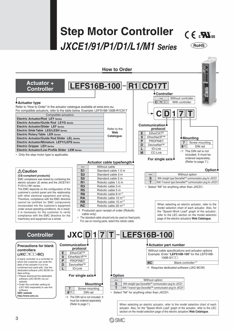
Option
— Without option
S With straight type DeviceNet™ communication plug for JXCD1
T With T-branch type DeviceNet™ communication plug for JXCD1
Option
— Without option
S With straight type DeviceNet™ communication plug for JXCD1
T With T-branch type DeviceNet™ communication plug for JXCD1
LEFS16B-100
JXC
R1 CD17T
7D T LEFS16B-100
How to Order
Actuator + Controller
Controller 1
1D T7C
®
A blank controller is a controller to
which the customer can write the
data of the actuator it is to be
combined and used with. Use the
dedicated software (JXC-BCW) for
data writing.
• Please download the dedicated
software (JXC-BCW) via our
website.
• Order the controller setting kit
(LEC-W2) separately to use this
software.
SMC website
http://www.smc.eu
Precautions for blank
controllers
(JXC�1��-BC)
Step Motor Controller
JXCE1/91/P1/D1/L1/M1 Series
Actuator cable type/length
— Without cable
S1 Standard cable 1.5 m
S3 Standard cable 3 m
S5 Standard cable 5 m
R1 Robotic cable 1.5 m
R3 Robotic cable 3 m
R5 Robotic cable 5 m
R8 Robotic cable 8 m∗1
RA Robotic cable 10 m∗1
RB Robotic cable 15 m∗1
RC Robotic cable 20 m∗1
∗1 Produced upon receipt of order (Robotic
cable only)
∗ The standard cable should only be used on fi xed parts.
For use on moving parts, select the robotic cable.
Actuator typeRefer to “How to Order” in the actuator catalogue available at www.smc.eu.
For compatible actuators, refer to the table below. Example: LEFS16B-100B-R1C917
Compatible actuators
Refer to the
Web
Catalogue.
Electric Actuator/Rod LEY Series
Electric Actuator/Guide Rod LEYG Series
Electric Actuator/Slider LEF Series
Electric Slide Table LES/LESH Series
Electric Rotary Table LER Series
Electric Actuator/Guide Rod Slider LEL Series
Electric Actuator/Miniature LEPY/LEPS Series
Electric Gripper LEH Series
Electric Actuator/Low-Profi le Slider LEM Series
∗ Only the step motor type is applicable.
[CE-compliant products]
EMC compliance was tested by combining the
electric actuator LE series and the JXCE1/91/
P1/D1/L1/M1 series.
The EMC depends on the confi guration of the
customer’s control panel and the relationship
with other electrical equipment and wiring.
Therefore, compliance with the EMC directive
cannot be certified for SMC components
incorporated into the customer’s equipment
under actual operating conditions. As a result,
it is necessary for the customer to verify
compliance with the EMC directive for the
machinery and equipment as a whole.
Caution
Controller
— Without controller
C�1�� With controller
Communication protocol
E EtherCAT®
9 EtherNet/IP™
P PROFINET
D DeviceNet™
L IO-Link
M CC-Link
For single axis
When selecting an electric actuator, refer to the
model selection chart of each actuator. Also, for
the “Speed–Work Load” graph of the actuator,
refer to the LEC section on the model selection
page of the electric actuators Web Catalogue.
∗1 The DIN rail is not included. It must be ordered separately.
(Refer to page 7.)
Mounting
7 Screw mounting
8∗1 DIN rail
For single axis
Communicationprotocol
E EtherCAT ®
9 EtherNet/IP™
P PROFINET
D DeviceNet™
L IO-Link
Actuator part number
Without cable specifi cations and actuator options
Example: Enter “LEFS16B-100” for the LEFS16B-
100B-S1��.
BC Blank controller∗1
∗1 Requires dedicated software (JXC-BCW)
3
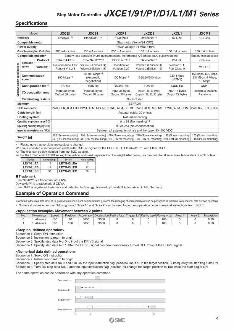
∗ Numerical values other than “Moving force,” “Area 1,” and “Area 2” can be used to perform operation under numerical instructions from JXCL1.
Specifi cations
Example of Operation Command
In addition to the step data input of 64 points maximum in each communication protocol, the changing of each parameter can be performed in real time via numerical data defi ned operation.
<Application example> Movement between 2 points
No. Movement mode Speed Position Acceleration Deceleration Pushing force Trigger LV Pushing speed Moving force Area 1 Area 2 In position
0 1: Absolute 100 10 3000 3000 0 0 0 100 0 0 0.50
1 1: Absolute 100 100 3000 3000 0 0 0 100 0 0 0.50
<Step no. defi ned operation>Sequence 1: Servo ON instruction
Sequence 2: Instruction to return to origin
Sequence 3: Specify step data No. 0 to input the DRIVE signal.
Sequence 4: Specify step data No. 1 after the DRIVE signal has been temporarily turned OFF to input the DRIVE signal.
<Numerical data defi ned operation>Sequence 1: Servo ON instruction
Sequence 2: Instruction to return to origin
Sequence 3: Specify step data No. 0 and turn ON the input instruction fl ag (position). Input 10 in the target position. Subsequently the start fl ag turns ON.
Sequence 4: Turn ON step data No. 0 and the input instruction fl ag (position) to change the target position to 100 while the start fl ag is ON.
The same operation can be performed with any operation command.
0 10 100
Sequence 1�
Sequence 2�
Sequence 3�
Sequence 4�
Model JXCE1 JXC91 JXCP1 JXCD1 JXCL1 JXCM1
Network EtherCAT ® EtherNet/IP™ PROFINET DeviceNet™ IO-Link CC-Link
Compatible motor Step motor (Servo/24 VDC)
Power supply Power voltage: 24 VDC ±10%
Current consumption (Controller) 200 mA or less 130 mA or less 200 mA or less 100 mA or less 100 mA or less 100 mA or less
Compatible encoder Battery-less absolute (4096 pulse/rotation), Incremental A/B phase (800 pulse/rotation) Battery-less absolute
Co
mm
un
icat
ion
sp
ecifi
cati
on
s Applicable
system
Protocol EtherCAT®∗2 EtherNet/IP™∗2 PROFINET∗2 DeviceNet™ IO-Link CC-Link
Version∗1 Conformance Test
Record V.1.2.6
Volume 1 (Edition 3.14)
Volume 2 (Edition 1.15)
Specifi cation
Version 2.32
Volume 1 (Edition 3.14)
Volume 3 (Edition 1.13)
Version 1.1
Port Class AVer. 1.10
Communication
speed100 Mbps∗2
10/100 Mbps∗2
(Automatic
negotiation)
100 Mbps∗2 125/250/500 kbps230.4 kbps
(COM3)
156 kbps, 625 kbps,
2.5 Mbps, 5 Mbps,
10 Mbps
Confi guration fi le∗3 ESI fi le EDS fi le GSDML fi le EDS fi le IODD fi le CSP+
I/O occupation areaInput 20 bytes
Output 36 bytes
Input 36 bytes
Output 36 bytes
Input 36 bytes
Output 36 bytes
Input 4, 10, 20 bytes
Output 4, 12, 20, 36 bytes
Input 14 bytes
Output 22 bytes
1 station, 2 stations,
4 stations
Terminating resistor Not included
Memory EEPROM
LED indicator PWR, RUN, ALM, ERR PWR, ALM, MS, NS PWR, ALM, SF, BF PWR, ALM, MS, NS PWR, ALM, COM PWR, ALM, L ERR, L RUN
Cable length [m] Actuator cable: 20 or less
Cooling system Natural air cooling
Operating temperature range [°C] 0 to 55 (No freezing)∗4
Operating humidity range [%RH] 90 or less (No condensation)
Insulation resistance [MΩ] Between all external terminals and the case: 50 (500 VDC)
Weight [g]220 (Screw mounting)
240 (DIN rail mounting)
210 (Screw mounting)
230 (DIN rail mounting)
220 (Screw mounting)
240 (DIN rail mounting)
210 (Screw mounting)
230 (DIN rail mounting)
190 (Screw mounting)
210 (DIN rail mounting)
170 (Screw mounting)
190 (DIN rail mounting)
∗1 Please note that versions are subject to change.
∗2 Use a shielded communication cable with CAT5 or higher for the PROFINET, EtherNet/IP™, and EtherCAT®.
∗3 The fi les can be downloaded from the SMC website.
∗4 For the LEY40 and LEYG40 series, if the vertical work load is greater than the weight listed below, use the controller at an ambient temperature of 40°C or less.
Series Weight [kg] Series Weight [kg]
LEY40�EA 9 LEYG40�EA 7
LEY40�EB 19 LEYG40�EB 17
LEY40�EC 38 LEYG40�EC 36
�TrademarkEtherNet/IP™ is a trademark of ODVA.
DeviceNet™ is a trademark of ODVA.
EtherCAT® is registered trademark and patented technology, licensed by Beckhoff Automation GmbH, Germany.
4
Step Motor Controller JXCE1/91/P1/D1/L1/M1 Series
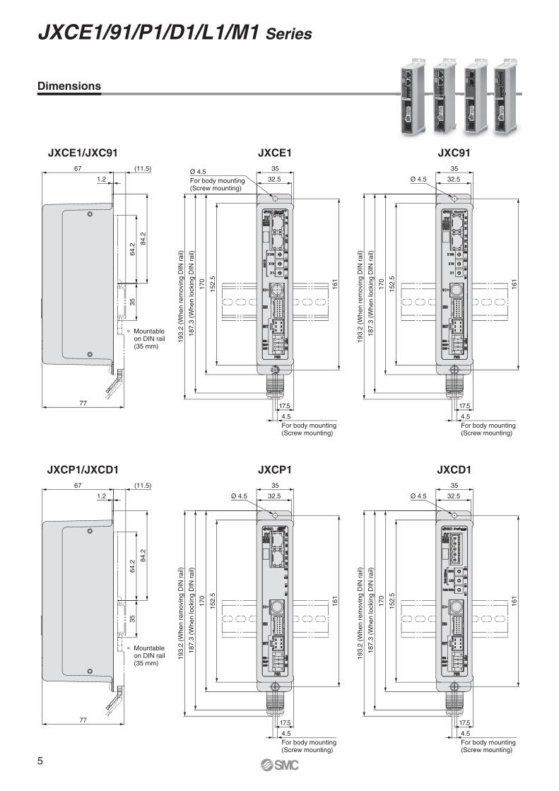
Ø 4.5 32.5
35
16
1
15
2.5
17
0
18
7.3
(W
he
n lo
ckin
g D
IN r
ail)
19
3.2
(W
he
n r
em
ovin
g D
IN r
ail)
17.5
JXCE1 JXC91JXCE1/JXC91
JXCP1 JXCD1JXCP1/JXCD1
∗ Mountable on DIN rail (35 mm)
16
1
32.5
35
Ø 4.5
15
2.5
17
0
18
7.3
(W
he
n lo
ckin
g D
IN r
ail)
19
3.2
(W
he
n r
em
ovin
g D
IN r
ail)
17.577
84
.2
64
.23
5
1.2
(11.5)67
∗ Mountable on DIN rail (35 mm)
77
84
.2
64
.23
5
1.2
(11.5)67
17.5
16
1
15
2.5
17
0
18
7.3
(W
he
n lo
ckin
g D
IN r
ail)
19
3.2
(W
he
n r
em
ovin
g D
IN r
ail)
Ø 4.5 32.5
35
16
1
32.5
35Ø 4.5
For body mounting(Screw mounting)
15
2.5
17
0
18
7.3
(W
he
n lo
ckin
g D
IN r
ail)
19
3.2
(W
he
n r
em
ovin
g D
IN r
ail)
17.5
4.5
For body mounting(Screw mounting)
4.5
For body mounting(Screw mounting)
4.5
For body mounting(Screw mounting)
4.5
For body mounting(Screw mounting)
Dimensions
5
JXCE1/91/P1/D1/L1/M1 Series
77
84.2
64.2
35
1.2
(11.5)67
17.5
161
32.5
35
152.5
170
161
152.5
170
17.5
32.5
35
1.2
67
84.2
64.2
35
(77)
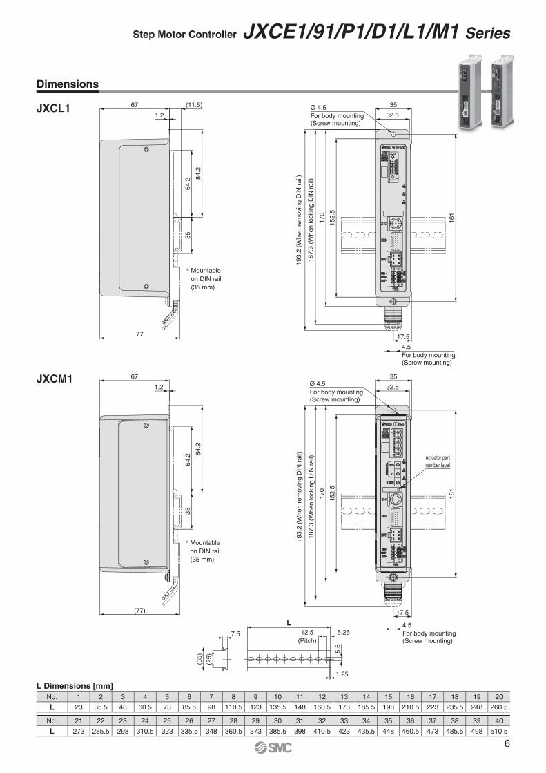
Dimensions
L Dimensions [mm]
No. 1 2 3 4 5 6 7 8 9 10 11 12 13 14 15 16 17 18 19 20
L 23 35.5 48 60.5 73 85.5 98 110.5 123 135.5 148 160.5 173 185.5 198 210.5 223 235.5 248 260.5
No. 21 22 23 24 25 26 27 28 29 30 31 32 33 34 35 36 37 38 39 40
L 273 285.5 298 310.5 323 335.5 348 360.5 373 385.5 398 410.5 423 435.5 448 460.5 473 485.5 498 510.5
JXCL1
JXCM1
Ø 4.5
For body mounting(Screw mounting)
19
3.2
(W
he
n r
em
ovin
g D
IN r
ail)
18
7.3
(W
he
n lo
ckin
g D
IN r
ail)
* Mountable
on DIN rail
(35 mm)
4.5
For body mounting(Screw mounting)
Ø 4.5
For body mounting(Screw mounting)
Actuator partnumber label
193.2
(W
hen r
em
ovin
g D
IN r
ail)
187.3
(W
hen lockin
g D
IN r
ail)
* Mountable
on DIN rail
(35 mm)
4.5
For body mounting(Screw mounting)
7.5
(25)
(35)
L
5.5
5.2512.5
(Pitch)
1.25
6
Step Motor Controller JXCE1/91/P1/D1/L1/M1 Series
300
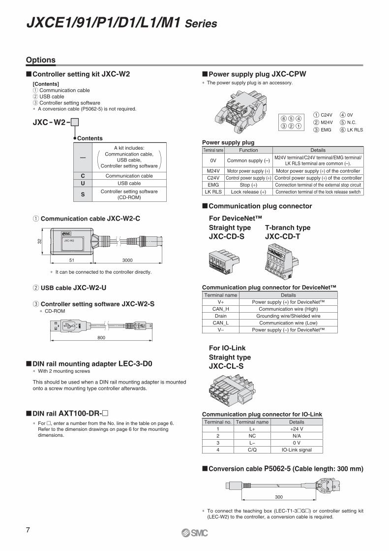
JXC-W2
300051
800
32
q Communication cable JXC-W2-C
w USB cable JXC-W2-U
e Controller setting software JXC-W2-S∗ CD-ROM
�DIN rail mounting adapter LEC-3-D0∗ With 2 mounting screws
�DIN rail AXT100-DR-�
Straight type
JXC-CL-S
For DeviceNet™
For IO-Link
∗ For �, enter a number from the No. line in the table on page 6.
Refer to the dimension drawings on page 6 for the mounting
dimensions.
This should be used when a DIN rail mounting adapter is mounted
onto a screw mounting type controller afterwards.
Communication plug connector for IO-Link
Terminal no. Terminal name Details
1 L+ +24 V
2 NC N/A
3 L− 0 V
4 C/Q IO-Link signal
∗ It can be connected to the controller directly.
Options
�Conversion cable P5062-5 (Cable length: 300 mm)
�Power supply plug JXC-CPW∗ The power supply plug is an accessory.
Straight type
JXC-CD-S
T-branch type
JXC-CD-T
�Communication plug connector
Power supply plug
Terminal name Function Details
0V Common supply (–)M24V terminal/C24V terminal/EMG terminal/
LK RLS terminal are common (–).
M24V Motor power supply (+) Motor power supply (+) of the controller
C24V Control power supply (+) Control power supply (+) of the controller
EMG Stop (+) Connection terminal of the external stop circuit
LK RLS Lock release (+) Connection terminal of the lock release switch
6
3
5
2
4
1
4 0V
2 M24V
1 C24V
5 N.C.
3 EMG 6 LK RLS
Communication plug connector for DeviceNet™
Terminal name Details
V+ Power supply (+) for DeviceNet™
CAN_H Communication wire (High)
Drain Grounding wire/Shielded wire
CAN_L Communication wire (Low)
V– Power supply (–) for DeviceNet™
�Controller setting kit JXC-W2
[Contents]
q Communication cable
w USB cable
e Controller setting software∗ A conversion cable (P5062-5) is not required.
Contents
—
A kit includes:
Communication cable,
USB cable,
Controller setting software
C Communication cable
U USB cable
SController setting software
(CD-ROM)
JXC W2
∗ To connect the teaching box (LEC-T1-3�G�) or controller setting kit
(LEC-W2) to the controller, a conversion cable is required.
7
JXCE1/91/P1/D1/L1/M1 Series
JXCE1/91/P1/D1 Series
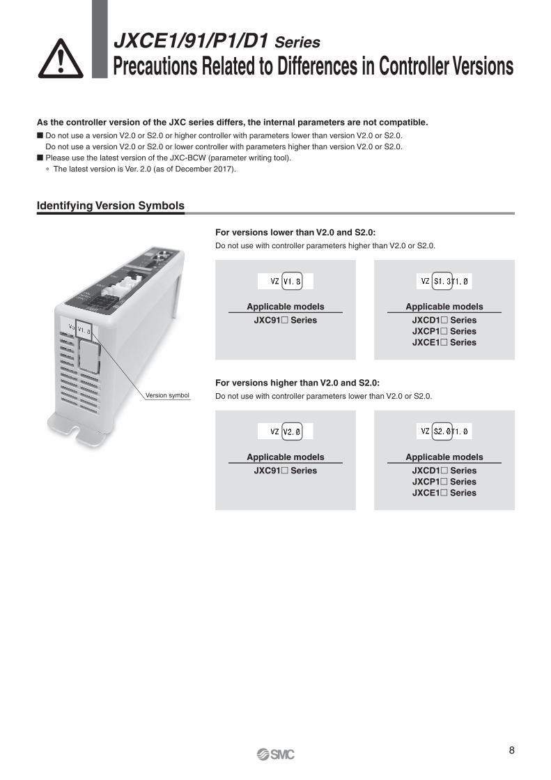
Precautions Related to Differences in Controller Versions
As the controller version of the JXC series differs, the internal parameters are not compatible.
� Do not use a version V2.0 or S2.0 or higher controller with parameters lower than version V2.0 or S2.0.
Do not use a version V2.0 or S2.0 or lower controller with parameters higher than version V2.0 or S2.0.
� Please use the latest version of the JXC-BCW (parameter writing tool).
∗ The latest version is Ver. 2.0 (as of December 2017).
Identifying Version Symbols
Version symbol
For versions lower than V2.0 and S2.0:
Do not use with controller parameters higher than V2.0 or S2.0.
For versions higher than V2.0 and S2.0:
Do not use with controller parameters lower than V2.0 or S2.0.
JXC91� Series
JXC91� Series JXCD1� Series
JXCP1� Series
JXCE1� Series
JXCD1� Series
JXCP1� Series
JXCE1� Series
Applicable models
Applicable modelsApplicable models
Applicable models
8


Lithuania +370 5 2308118 www.smclt.lt [email protected]
Netherlands +31 (0)205318888 www.smcpneumatics.nl [email protected]
Norway +47 67129020 www.smc-norge.no [email protected]
Poland +48 222119600 www.smc.pl [email protected]
Portugal +351 226166570 www.smc.eu [email protected]
Romania +40 213205111 www.smcromania.ro [email protected]
Russia +7 8127185445 www.smc-pneumatik.ru [email protected]
Slovakia +421 (0)413213212 www.smc.sk [email protected]
Slovenia +386 (0)73885412 www.smc.si [email protected]
Spain +34 902184100 www.smc.eu [email protected]
Sweden +46 (0)86031200 www.smc.nu [email protected]
Switzerland +41 (0)523963131 www.smc.ch [email protected]
Turkey +90 212 489 0 440 www.smcpnomatik.com.tr [email protected]
UK +44 (0)845 121 5122 www.smcpneumatics.co.uk [email protected]
Specifications are subject to change without prior notice and any obligation on the part of the manufacturer.
SMC CORPORATION Akihabara UDX 15F, 4-14-1, Sotokanda, Chiyoda-ku, Tokyo 101-0021, JAPAN Phone: 03-5207-8249 FAX: 03-5298-53621st printing YY printing YY 00 Printed in Spain
Austria +43 (0)2262622800 www.smc.at [email protected]
Belgium +32 (0)33551464 www.smcpneumatics.be [email protected]
Bulgaria +359 (0)2807670 www.smc.bg [email protected]
Croatia +385 (0)13707288 www.smc.hr [email protected]
Czech Republic +420 541424611 www.smc.cz [email protected]
Denmark +45 70252900 www.smcdk.com [email protected]
Estonia +372 6510370 www.smcpneumatics.ee [email protected]
Finland +358 207513513 www.smc.fi [email protected]
France +33 (0)164761000 www.smc-france.fr [email protected]
Germany +49 (0)61034020 www.smc.de [email protected]
Greece +30 210 2717265 www.smchellas.gr [email protected]
Hungary +36 23513000 www.smc.hu [email protected]
Ireland +353 (0)14039000 www.smcpneumatics.ie [email protected]
Italy +39 0292711 www.smcitalia.it [email protected]
Latvia +371 67817700 www.smclv.lv [email protected]
SMC Corporation (Europe)