Embed Size (px)
Citation preview

800 826 5537 05/16/2016
1
Model Number:_______________ Serial Number:________________
Information Manual…… Rev 12.16F Installation and
Troubleshooting Instructions for Electric Tankless Commercial Water Heaters
CF SERIES ONLY
CF 144
KW,CF 120 KW CF 108 KW, CF 90 KW, or CF 81 KW
CF 48 KW, CF 54 KW, or CF 72 KW
CF 24 KW , CF 27 KW, or CF 36 KW CF 12 KW, CF 15 KW, CF 18 KW
FOR MORE DETAILED SCHEMATICS AND WIRING DIAGRAMS VISIT,
HOTWATERHEATER.COM
2060 B Whitfield Park Avenue * Sarasota, Florida 34243 * 800-826-5537 * [email protected]

800 826 5537 05/16/2016
2
Table of Contents __________________________________
INFORMATION MANUAL for Commercial Heaters – CF 12 KW, CF 15
KW, CF 18 KW, CF 24 KW, CF 27 KW, CF 36 KW, CF 48 KW,
CF 54 KW, CF 60 KW, CF 72 KW, CF 81 KW, CF 90 KW, CF 108 KW,CF120 KW, CF 144 KW
PAGE #
How a CF Series Heater Works 3
Engineering Information and Breaker Sizes 4
Recovery Capacities Chart 5
CF Series Installation Instructions 6-7
Bill of Materials and Assembly drawings discussion 8
CF 12 KW, CF15 KW, CF 18 KW 9
CF 24 KW,CF 27 KW,CF 36 KW 10
CF 48 KW,CF 54 KW, CF 60 KW CF 72 KW 11
C 81KW, C 90 KW, C 108 KW 12
CF 120 KW ,CF 144 KW
Troubleshooting CF Series 13-16
Parts replacement procedures 17-21
Wiring diagram 12,15,18 KW 208 volt only 22
Wiring Diagram 18,24,27,36 480 volt only 23
Wiring diagram 48, 54 , 72 480 volt only 24
Wiring diagram 81, 90, 108 480 volt only 25
Wiring diagram 120,144 480 volt only 26
Cut sheets 3 element, 6 element, 12 element,
18 element 24 element 27-31

800 826 5537 05/16/2016
3
How a CF Series Heater Works:
We have four lines of heaters; electromechanical (CF series), electronic (CE series) electronic caustic fluids (CERO),and
Restaurant Boosters (CR). They both heat the fluid as it passes thru but they are controlled in different manners
depending on the customer’s needs.
This manual covers the CF models only.
CF models: When a hot water tap is opened, the cold water entering the heater passes thru the first heat chamber from
right to left over the first thermostat , the thermostat closes turning on the first electrical heat coil, and the coil heats
the water as it passes directly over it.
Depending on the size of the heater there are three, six, twelve, eighteen or twenty four thermostats and elements.
Once the water reaches the temperature setting on the thermostat the thermostat does not close and that
corresponding element and all later elements do not turn on.
The heat exchanger maintains hot water as a type of mini boiler at all times.
The amount of energy needed is in direct proportion to the volume of hot water flow being used, thereby using only the
energy needed. When the hot water is turned off, the flow of energy turns off as well. Your hot water tap is an ignition
key for energy used to heat all the hot water you need.
The following charts show the full load AMP draw and physical size for each of our units (engineering chart) and the
capabilities of each unit(recovery chart) in terms of temperature rise at a certain flow rate.

800 826 5537 05/16/2016
4
.

800 826 5537 05/16/2016
5

800 826 5537 05/16/2016
6
Installation Instructions CF Series heaters
1. Double check to be sure you ordered and we supplied the correct voltage unit. The voltage on our unit is listed
on the label on the front cover.
2. All units have cold in the bottom and hot out the top.
3. Be sure to use a large enough breaker per the National Electric Code and large enough wire to meet code.
Installation by a licensed electrician will insure this happens.
4. Our smaller units mount to the wall and the larger ones can be floor mounted. For the units in sizes from 12 KW
thru 72 KW without a NEMA 4 enclosure use the provided brackets to mount the unit to the wall. For the 81KW
thru 108 Kw without a NEMA 4 enclosure the brackets mounted to the side of the unit are used to mount the
unit to the wall.
5. For the NEMA 4 enclosures use the feet provided to mount the heater to a wall or floor mount the unit using
the C channel on the bottom of the enclosure.
6. For all units using 185 thermostats or below we provide a pressure relief valve that should be plumbed to a
drain.
7. After the unit is properly plumbed in turn on the water flow and check for leaks.
8. Turn the delay switch to 1 which means the unit will turn on one minute after the control circuit is satisfied.
9. While flowing water thru the unit turn on the breaker and heater switch.
10. The circuit control light on the outside of the unit will light when the pressure switch and flow switch and timer
have been satisfied.
11. Run a high volume of water thru the unit and check for AMP draw. Compare the AMP draw you get with the
label on the unit. If you are not getting a full load AMP draw you will need to check each of the elements to see
if you have a burned fuse or element.
12. The unit is now operational.
800 826 5537 05/16/2016
7
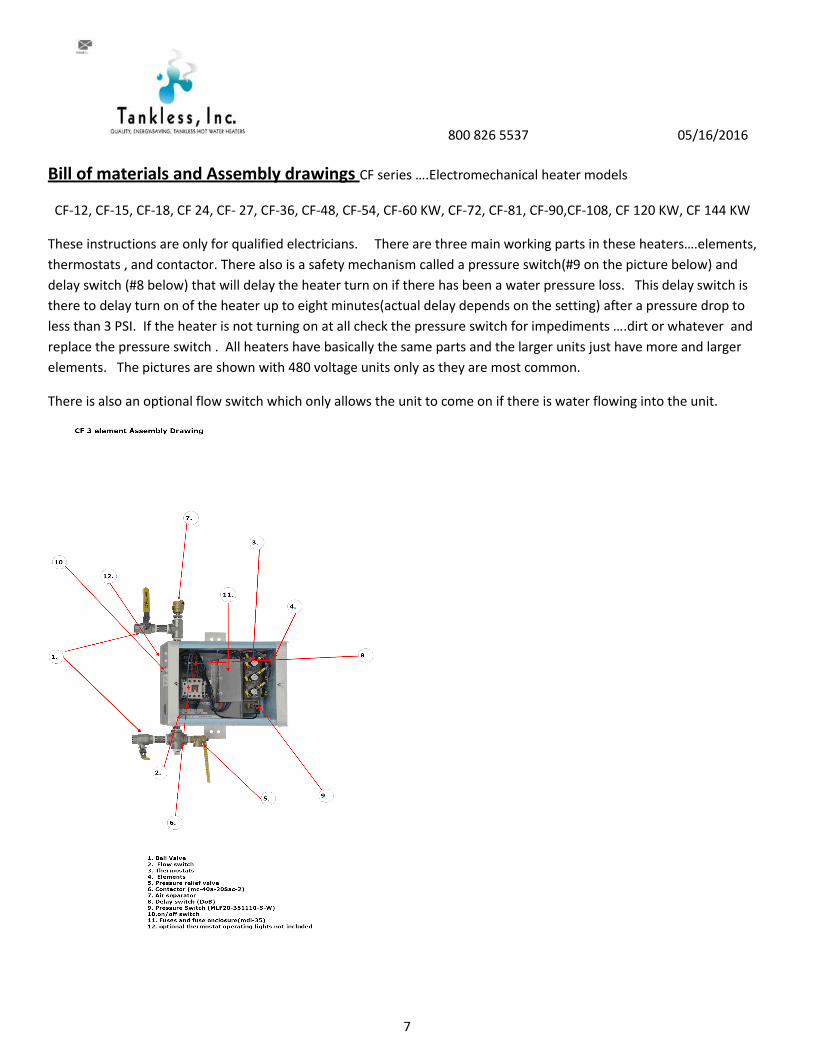
Bill of materials and Assembly drawings CF series ….Electromechanical heater models
CF-12, CF-15, CF-18, CF 24, CF- 27, CF-36, CF-48, CF-54, CF-60 KW, CF-72, CF-81, CF-90,CF-108, CF 120 KW, CF 144 KW
These instructions are only for qualified electricians. There are three main working parts in these heaters….elements,
thermostats , and contactor. There also is a safety mechanism called a pressure switch(#9 on the picture below) and
delay switch (#8 below) that will delay the heater turn on if there has been a water pressure loss. This delay switch is
there to delay turn on of the heater up to eight minutes(actual delay depends on the setting) after a pressure drop to
less than 3 PSI. If the heater is not turning on at all check the pressure switch for impediments ….dirt or whatever and
replace the pressure switch . All heaters have basically the same parts and the larger units just have more and larger
elements. The pictures are shown with 480 voltage units only as they are most common.
There is also an optional flow switch which only allows the unit to come on if there is water flowing into the unit.

800 826 5537 05/16/2016
8
The picture below shows our CF 36 unit in a non NEMA 4 box and is also applicable for the 24 KW, 27 KW, and 36 KW
units. This picture is of a 480 volt unit.

800 826 5537 05/16/2016
9
The next assembly drawing is of the CF 48 KW unit and it is also applicable for the CF 54 KW and CF 72 KW units except
the element part numbers change.
For the 72 KW the element part number is 6KW240Velem. For the 54 KW model the elementpart number is
6KW277Velem.
800 826 5537 05/16/2016
10
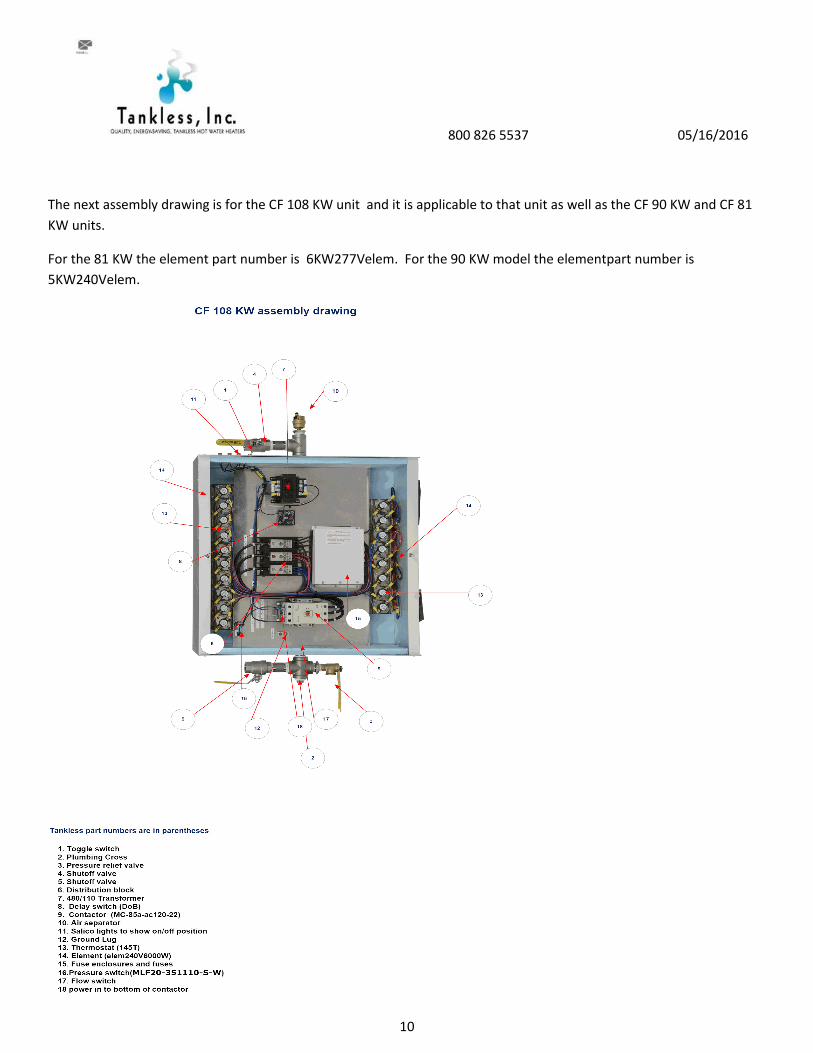
The next assembly drawing is for the CF 108 KW unit and it is applicable to that unit as well as the CF 90 KW and CF 81
KW units.
For the 81 KW the element part number is 6KW277Velem. For the 90 KW model the elementpart number is
5KW240Velem.

800 826 5537 05/16/2016
11
The picture below shows the assembly drawing for the CF 144 KW unit in a NEMA 4 enclosure.

800 826 5537 05/16/2016
12
Troubleshooting
You will need the following items to test the units: continuity tester, Voltage meter, Amp meter, and Ohms meter.
The optional lights on the sides of the units are to show which elements are engaged. If you have a NEMA 4 unit you
have only a pilot light outside and the contactors will indicate their engagement or lack therof by the buttons on the
contactor pulling in or not. You will have to open the door to observe the units operation.
The thermostats activate the elements. With normal operation at maximum flow or when you first turn on the switch
all lights will be on …. the contactor buttons pulled in as long as there is water pressure coming to the unit. The lights
and buttons will go on or off in series as the elements are engaged. The heater is designed to only use the thermostats
and elements necessary to heat the water needed at any given time.
Fluctuation in temperature can often be remedied by a simple adjustment of the outflow valve on the left side of the
heater or it can be a more serious problem. Fluctation in hot water, lukewarm water, or no hot water at all, are almost
always signs that indicate element, contactor or thermostat failure.
Note: Where the heater fails to maintain the desired temperature you may be running the water faster than the heater
is capable of heating the water.
Use the following steps to diagnose a problem.
Step 1: Turn off all power supply CAUTION FAILURE TO TURN OFF ALL POWER COULD RESULT IN SERIOUS INJURY OR
DEATH FROM ELECTROCUTION.
Step 2: Check for any loose connections, properly operating breakers, etc.
Step 3: Turn off the switch to the heater.
Step 4: Turn the delay switch all the way to the left..0.
Step 5: Purge the heater. Run water thru the heater to cool it down. This will reset the thermostats.
Step 6: Turn the water flow on. Turn the main breaker back on. Turn on the heater switch.
Check to see if the contactor pulls in. When you first turn on the switch the contactor should pull in. That indicates the
pressure switch and optional flow switch requirements have been met for theunit to turn on. If that is the case then
proceed to step 8. If the contactor does not pull in ….the buttons do not pull in on the contactor … do the continuity test
as shown in step 7.
Step 7: Testing the flow switch and pressure switch. Turn off the power supply at the main breaker and the switch to
the heater. CAUTION FAILURE TO TURN OFF ALL POWER COULD RESULT IN SERIOUS INJURY OR DEATH FROM
ELECTROCUTION.
Check for continuity across the pressure switch. If it is there the switch is closed and allowing electricity to flow thru the
circuit. It it is not closed the switch could be plugged with impediment. More than likely thewater pressure is not high
enough to close the switchwhich requires 3 psi.

800 826 5537 05/16/2016
13
With water flowing thru the unit check the continuity across the poles of the flow switch if you purchased this option.
The flow must be 2-3 gallons per minute to close this switch and allow electricity to flow thru the switch.
Step 8 Checking continuity of thermostats
The thermostats have two funtions: one to regulate the turn on and off side of the units and to act as a safety in case of
overheating. The thermostat can fail if a large amount of air goes into the unit and there is no flow switch and the
elements overheat the water that is there to over 260 degrees . At that point the fuse side of the thermostat will burn
and the thermostat will never work again. The thermostat will have continuity if the fuse side of the thermostat is still
good.
The thermostats condition is determined by a continuity check AFTER POWER IS OFF AND AFTER COLD WATER HAS BEEN
RUN THRU THE HEATER TO RESET THE THERMOSTATS.
Continuity is tested between the arms on the thermostat. Occasionally, you get a false positive on a thermostat. It may
read as good but have a weak connection.
If a thermostat tests as “no continuity” the thermostat should be replaced and the technician should determine what
else could have caused the thermostat to fail. It is possible for the operator to shut off the cold water supply to the
heater and blow all the thermostats but that is an abnormal occurrence.
The unit has a pressure switch to shut the heater down in that case but there is no 100% protection against air entering
the unit on its restart.
Step 9: Ohms Test on Elements : If the contactor is pulling in and you still have bad performance(not hot enough,
fluctations) you may have a failed element. Check each element with an OHMs meter for correct readings. If the
elements reads 0 or flickers it is bad and needs to be replaced. If the failed element looks like it was split from the inside
it probably failed due to air in the heater and you need to check the water source for a problem. 6KW 240 volts= 10
OHMS
6 KW 208 volts= 7.2 OHMS 5.3 KW 208 volts= 8.2 OHMS 5 KW 240 volts= 12.2 OHMS
4.5 KW 240 voltsor 6 KW at 277 volts = 13 OHMS 4 KW 240 volts or 6 KW at 288 volts= 15 OHMS
3 KW 240 volts= 19.5 OHMS
Step 10: Testing the fuses
If you have a failed element it is possible that you have a failed fuse so you must check the fuse to the element for
continuity.
1. Remove the fuse from the holder and check for continuity.
2. The optional thermostat lights will tell you if the element is working.
3. If you need to replace the fuse be sure and use the correct size based on the AMP draw of the element.
Step 11: Checking for leaks

800 826 5537 05/16/2016
14
If you have a leak there are four possible reasons
1. A plumbing leak that can be fixed at the site. Pipes not tight or valve not tight.
2. The o ring on the element failed.
3. The o ring on the thermostat failed.
4. Other leaks from the exchanger which is a more serious problem that will probably require a factory repair.
This an extremely unlikely situation.
Turn off the main power.
Take paper towel and dry off the heater. Take another paper towel to find the leak source….either around the element
or the thermostat. If the leak is at the element or thermostat; then
1. Drain all water from the heater
2. Take the element out and examine it for damage and test it for OHMS see step 8
3. Test the thermostat for continuity.
4. Order a new element or thermostat
5. Put in a new o ring if neither part failed but there is a leak at the part. You should have some in your spare parts
kit. If you install a new element o ring be sure to not over tighten the element on reinstall.
If neither of these is the entire problem the unit will have to be sent back to the factory.
Parts replacement procedures. Procedures are shown for the main wear items in the unit.
Before doing any parts replacement do the following.
1. Be sure power is off to the heater by checking the separate disconnect provided for this unit.
2. Shut off water flow to the unit from the inbound side.
3. Drain water from the unit by either opening the plug on the left bottom of the unit or opening a
usage spigot in you system to relieve the water pressure inside the unit.
Element replacement.
1. Remove the top cover to the unit.
2. Using a phillips screwdriver remove the wires from the element that tested as needing replacement.
3. Using a 1 ½ scoket wrench remove the element. The element is seated with a right hand thread.
4. Insert the new element being sure the element has the O ring with it the factory provided.
5. Tighten the element down with the wrench…SNUG. Do not over tighten or you will ruin the o ring.
6. After all elements are replaced andbefore doing any wire replacement run water thru the heater to be sure
the elements aresealed and tighten if necessary.

800 826 5537 05/16/2016
15
7. Reattach the wires to the elements.
Thermostat replacement
1. Be sure the water is drained from the unit before starting as indicated above.
2. Remove the wires to the thermostat with a flathead scredriver
3. Remove the allen screws that hold the clips down with a ¼ allen wrench. A T handle wrench is
recommended.
4. Remove the thermostatand replace it with the new one being sure the new one is the exact
same item…a 125T puts out 125 F water and a 185 T puts out 185 F water. Do not mix them up.
5. Replace the thermostat slips being sure they are concave down so they create a tight seal. The underside
has a sharp edge to it …be sure the sharp edge is down. Also be sure you use the factory provided o ring on
the thermostatto provide a seal.
6. Reinsert the allen screws
7. Reattach the wires being sure to tighten them but do not over tighten them or you will break the
thermostat at the tab.
Contactor replacement procedures
1. Be sure the power to the unit is off.
2. Remove the element and thermostat wires.
3. Removethe mounting screws on the side of the contactor.
4. Replace the contactor with the new one being sure the part number matches exactly. The part number is made
up of four parts.
a. Prefix=MC
b. Motor load AMP rating which is approximately 150 % of full load AMP draw in a resitance heater. A 100a
would be the equivalent of a 150 full load AMP draw in a resistance heater.
c. 120AC = coil voltage. If you have 480 or 575 the coil voltage is 120. If you have 208 the coil voltage is 208.
If you have 240 voltage the coil voltage is 240. You MUST know your voltage before installing a new part
and you must be sure you did not buy the wrong voltage unit.
d. Suffix 2 or 22
5. Rewire the element and thermostat wires exactly like they were and refer to the matching contactors in other
positions of the wiring diagram provided with this manual.
Transformer replacement would be necessary in the unlikely occurrence of the contactor chattering after you verified
the power to the unit is a true 480 and you do not have voltage variance.
1. Be sure he power is off.
2. Check for continuity on the fuse FLM1-1/4 to be sure the problem is not just a fuse.
3. Replace the fuse if necessary.
4. Remove power wires from distribution block on lines 1 & 3 to the transformer.
5. Remove wire from transformer to the delay switch.
6. Remove old transformer from the plate by detcahing the screws at the cornerr of the transformer.

800 826 5537 05/16/2016
16
7. Replace with new transformer and rewire as before.
8. Double check to be sure the fuse on the transformer has continuity.
Vent valve replacement and operation.. 5F6M3
1. This valve vents off air if air is in the water lines.
2. If replacement is needed do the following
3. Be sure power to the unit is off.
4. Shut off the inbound water source to the unit
5. Drain waterfrom the unit
6. Remove and replace the valve with a crescent wrench.
Pressure switch replacement
1. The pressure switch could become blocked with trashand not allow the unit to come on.
2. Check for continuity across the poles of the switch with water pressure to the unit and the power off.
3. If you have continuity the pressure switch is not the problem.
4. To remove and replace the switch do the following
5. Be sure the power to the unit is off
6. Drain water from the unit
7. Remove wires from the switch
8. Remove and replace the switch using an open end wrench
9. Check for water leaks
10. Rewire the switch.
Pressure relief valve replacement
1. Sometimes these valves age and stick closed.
2. To replace shut off the power to the unit.
3. Drain water from unit
4. Remove and replace the valve with a wrench
5. Run water thru the heater
6. Check for leaks.
7. Open aluninum lever on the valve to be sue the valveworks as expected
Delay switch replacement
1. Be sure power is off.
2. Remove the wire from the transformer to the input on theswitch and the one from line on the switch to the
on/off switch and mark the wires.
3. Remove the old switch from the plate and replace it with the new one.
4. Rewire as before.
5. Set delay to 1 which means 1 minute.
800 826 5537 05/16/2016
17
Ball valve replacement
1. Be sure power to unit is off.
2. Shut off flow of water to the unit and drain the unit
3. Cut plumbing line before or after the unit to allow removal of the valve.
4. Install the valve and replumb.
5. Check for leaks and fix
Indicator light replacement
1. If all circuits are working and the lights do not come on then the light is the problem.
2. Be sure power to the unit is off.
3. Clip the wires to the light
4. Remove the light..it simply pops out of the hole
5. Install the new light
6. Rewire the new light as before to the two leads you just cut.
Toggle switch 452 BU
1. Be sure the power to the unit is off.
2. Remove the wires to the pressure switch and the delay switch
3. Remove the old switch by removing the nut that holds it in place
4. Install new switch
5. Reattach the wires
Terminal block 63133
1. Be sure the power to the unit is off
2. Remove the wires from lines 1 ,2, and 3. Please note they are color coded.
3. Remove theold block and replace it with the new one
4. Reattach the wires.
5. Double check that the wires are tight.
Fuses MDL 35 and KLK 30
1. Be sure the power to the unit is off.
2. Remove the fuse from the fuse holder.
3. Replace the fuse with a properly rated fuse. For elements larger than or equal to the 6000 W at 240 Volt
element use the 35 AMP fuse MDL 35 and for the smaller elements use part number ????????????
800 826 5537 05/16/2016
18
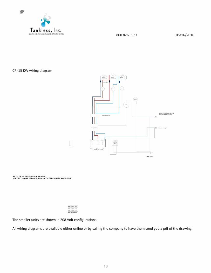
CF -15 KW wiring diagram
The smaller units are shown in 208 Volt configurations.
All wiring diagrams are available either online or by calling the company to have them send you a pdf of the drawing.

800 826 5537 05/16/2016
19
CF 36 KW 480 wirediagram All wiring diagrams are available either online or by calling the company to have them send
you a pdf of the drawing.
CF 72 KW 480 V wiring diagram All wiring diagrams are available either online or by calling the company to have them
send you a pdf of the drawing.

800 826 5537 05/16/2016
20
CF 108 KW 480 volt wiring diagram diagram All wiring diagrams are available either online or by calling the company to
have them send you a pdf of the drawing.

800 826 5537 05/16/2016
21

800 826 5537 05/16/2016
22
CF 144 KW 480 Volt wiring diagram All wiring diagrams are available either online or by calling the company to have
them send you a pdf of the drawing

800 826 5537 05/16/2016
23
CUT SHEETS..CF Series units All cut sheets are also available on line at hotwaterheater.com.

800 826 5537 05/16/2016
24
All cut sheets are also available on line at hotwaterheater.com.

800 826 5537 05/16/2016
25
All cut sheets are also available on line at hotwaterheater.com.

800 826 5537 05/16/2016
26
All cut sheets are also available on line at hotwaterheater.com.

800 826 5537 05/16/2016
27
All cut sheets are also available on line at hotwaterheater.com.