Embed Size (px)
Citation preview

Antenna Fundamentals – Technical Brief 2
This document and the information contained herein (collectively, the
“Information”) is provided to you (both the individual receiving this document
and any legal entity on behalf of which such individual is acting) (“You” and
“Your”) by AT&T, on behalf of itself and its affiliates (“AT&T”) for informational
purposes only. AT&T is providing the Information to You because AT&T believes the
Information may be useful to You. The Information is provided to You solely on the
basis that You will be responsible for making Your own assessments of the
Information and are advised to verify all representations, statements and
information before using or relying upon any of the Information. Although AT&T
has exercised reasonable care in providing the Information to You, AT&T does not
warrant the accuracy of the Information and is not responsible for any damages
arising from Your use of or reliance upon the Information. You further understand
and agree that AT&T in no way represents, and You in no way rely on a belief, that
AT&T is providing the Information in accordance with any standard or service
(routine, customary or otherwise) related to the consulting, services, hardware or
software industries.
AT&T DOES NOT WARRANT THAT THE INFORMATION IS ERROR-FREE. AT&T IS
PROVIDING THE INFORMATION TO YOU “AS IS” AND “WITH ALL FAULTS.” AT&T
DOES NOT WARRANT, BY VIRTUE OF THIS DOCUMENT, OR BY ANY COURSE OF
PERFORMANCE, COURSE OF DEALING, USAGE OF TRADE OR ANY COLLATERAL
DOCUMENT HEREUNDER OR OTHERWISE, AND HEREBY EXPRESSLY DISCLAIMS,
ANY REPRESENTATION OR WARRANTY OF ANY KIND WITH RESPECT TO THE
INFORMATION, INCLUDING, WITHOUT LIMITATION, ANY REPRESENTATION OR
WARRANTY OF DESIGN, PERFORMANCE, MERCHANTABILITY, FITNESS FOR A
PARTICULAR PURPOSE OR NON-INFRINGEMENT, OR ANY REPRESENTATION OR
WARRANTY THAT THE INFORMATION IS APPLICABLE TO OR INTEROPERABLE WITH

Antenna Fundamentals – Technical Brief 3
ANY SYSTEM, DATA, HARDWARE OR SOFTWARE OF ANY KIND. AT&T DISCLAIMS
AND IN NO EVENT SHALL BE LIABLE FOR ANY LOSSES OR DAMAGES OF ANY
KIND, WHETHER DIRECT, INDIRECT, INCIDENTAL, CONSEQUENTIAL, PUNITIVE,
SPECIAL OR EXEMPLARY, INCLUDING, WITHOUT LIMITATION, DAMAGES FOR
LOSS OF BUSINESS PROFITS, BUSINESS INTERRUPTION, LOSS OF BUSINESS
INFORMATION, LOSS OF GOODWILL, COVER, TORTIOUS CONDUCT OR OTHER
PECUNIARY LOSS, ARISING OUT OF OR IN ANY WAY RELATED TO THE
PROVISION, NON-PROVISION, USE OR NON-USE OF THE INFORMATION, EVEN IF
AT&T HAS BEEN ADVISED OF THE POSSIBILITY OF SUCH LOSSES OR DAMAGES.
© 2009 AT&T Intellectual Property. All rights reserved. AT&T and AT&T logo are
trademarks of
AT&T Intellectual Property.

Antenna Fundamentals – Technical Brief 4
Table of Contents
1. Introduction…............................................................................ 5 1.1 Audience ......................................................................... 5
1.2 Contact Information .......................................................... 5 1.3 AT&T Resources................................................................ 5
1.4 Terms and Acronyms......................................................... 6
2. Introduction.............................................................................. 7 3. Antenna Fundamentals.............................................................. 8
3.1 Antenna Impedance and Bandwidth..................................... 8 3.2 Antenna Efficiency........................................................... 10
3.3 Antenna Radiation Pattern and Polarization......................... 12 4. Antenna Selection and Implementation...........................................
14 4.1 Embedded vs. External.................................................... 14
4.1.1 External Antennas.............................................. 15
4.1.2 Embedded Antennas........................................... 15 4.2 Antenna Type and Location.............................................. 16
4.2.1 Embedded Antenna Type…………………..................... 16 4.3 Common Implementation Mistakes.................................... 19
4.4 Antenna Design and Implementation Assistance.................. 20 4.5 Antenna System Issues.................................................... 21
4.5.1 Connecting the Antenna....................................... 21 4.5.2 Self-Interference................................................. 21
4.5.3 Co-existence with Other Wireless Technologies........ 22
5. Antenna Performance Measurements........................................ 24 6. Antenna Issues Related to Product Certification ...................... 25
6.1 Using a Certified Radio Module........................................... 25 6.2 Transmit Mode Failures..................................................... 26
6.3 Receive Mode Failures...................................................... 26 6.4 Harmonic Generation Failures............................................ 26
6.5 Device Pre‐Testing............................................................. 27
7. Conclusion ................................................................................ 28

Antenna Fundamentals – Technical Brief 5
Revision History
All marks, trademarks, and product names used in this document are the property
of their respective owners.
Date Revision Description
January 27,
2009
1.0 First release of this paper.
December 2,
2009
1.5 Updated terminology.

Antenna Fundamentals – Technical Brief 6
1. Introduction
This white paper discusses antenna fundamentals, integrated antenna design and
selection, common antenna implementation issues, and antenna measurement for
emerging wireless devices.
1.1 Audience
The target audiences of this paper are OEMs and ODMs who are designing a
wireless device for the first time using a pre-certified radio module and want to
integrate the antenna into the device.
1.2 Contact Information
E-mail any comments or questions regarding this white paper via the AT&T
Developer Program. Please reference the title of this paper in the message.
1.3 AT&T Resources
AT&T Developer Program: http://developer.att.com
Mobile Application Development: http://developer.att.com/mobiledevelopment
Network Technology:
http://developer.att.com/developer/index.jsp?page=toolsTechSection&id=7600074
3G: http://developer.att.com/3G
Device Information: http://developer.att.com/devicedetails
Mobile Middleware: http://developer.att.com/middleware
Wireless Reference Architecture Material: http://developer.att.com/WRA
Certified Application Catalog: http://developer.att.com/certifiedsolutionscatalog
devCentral Resource on Platforms and Operating Systems
Antenna Fundamentals – Technical Brief 7
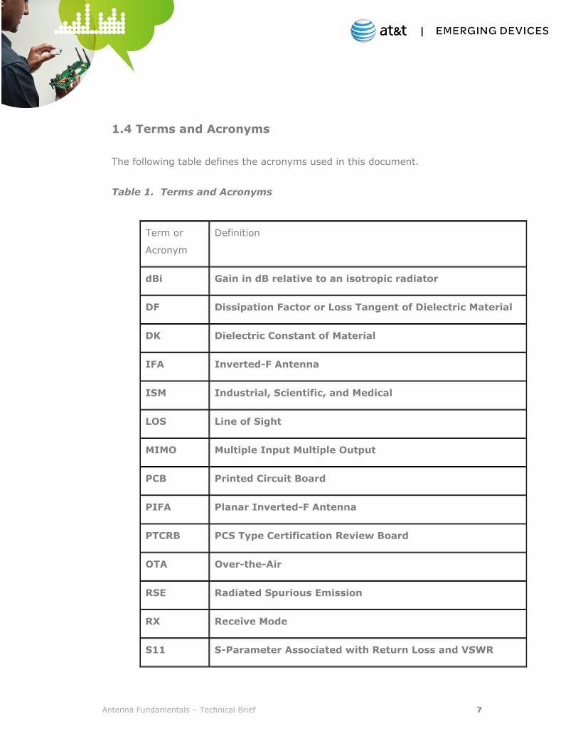
1.4 Terms and Acronyms
The following table defines the acronyms used in this document.
Table 1. Terms and Acronyms
Term or
Acronym
Definition
dBi Gain in dB relative to an isotropic radiator
DF Dissipation Factor or Loss Tangent of Dielectric Material
DK Dielectric Constant of Material
IFA Inverted-F Antenna
ISM Industrial, Scientific, and Medical
LOS Line of Sight
MIMO Multiple Input Multiple Output
PCB Printed Circuit Board
PIFA Planar Inverted-F Antenna
PTCRB PCS Type Certification Review Board
OTA Over-the-Air
RSE Radiated Spurious Emission
RX Receive Mode
S11 S-Parameter Associated with Return Loss and VSWR
Antenna Fundamentals – Technical Brief 8
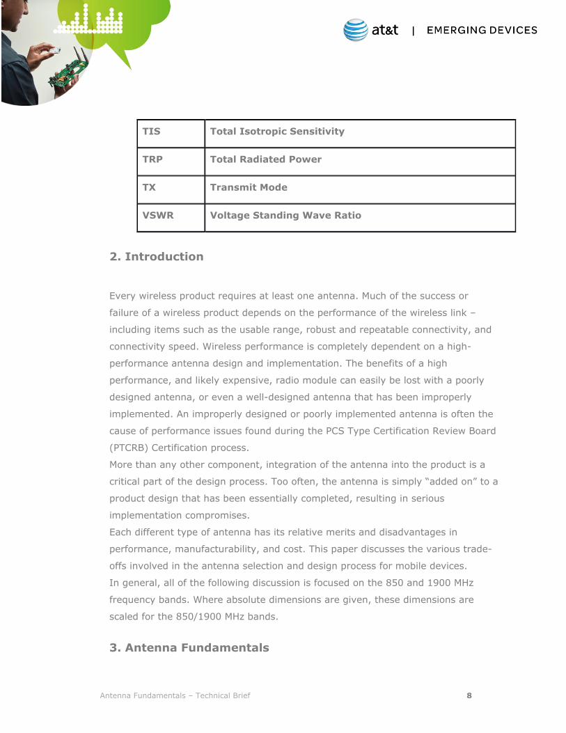
TIS Total Isotropic Sensitivity
TRP Total Radiated Power
TX Transmit Mode
VSWR Voltage Standing Wave Ratio
2. Introduction
Every wireless product requires at least one antenna. Much of the success or
failure of a wireless product depends on the performance of the wireless link –
including items such as the usable range, robust and repeatable connectivity, and
connectivity speed. Wireless performance is completely dependent on a high-
performance antenna design and implementation. The benefits of a high
performance, and likely expensive, radio module can easily be lost with a poorly
designed antenna, or even a well-designed antenna that has been improperly
implemented. An improperly designed or poorly implemented antenna is often the
cause of performance issues found during the PCS Type Certification Review Board
(PTCRB) Certification process.
More than any other component, integration of the antenna into the product is a
critical part of the design process. Too often, the antenna is simply “added on” to a
product design that has been essentially completed, resulting in serious
implementation compromises.
Each different type of antenna has its relative merits and disadvantages in
performance, manufacturability, and cost. This paper discusses the various trade-
offs involved in the antenna selection and design process for mobile devices.
In general, all of the following discussion is focused on the 850 and 1900 MHz
frequency bands. Where absolute dimensions are given, these dimensions are
scaled for the 850/1900 MHz bands.
3. Antenna Fundamentals
Antenna Fundamentals – Technical Brief 9
Antennas for wireless devices are as varied as the devices themselves. Possibilities
include external versus embedded, printed on flex printed-circuit boards (PCBs),
formed from thin sheet metal, created on the product housing using sprayed-on
conductive paint, embedded in materials with a high-dielectric constant for size
reduction, and so forth.
Regardless of the type and configuration of the antenna, performance can be
characterized by the same metrics:
Impedance Bandwidth
Efficiency
Directive Gain
Polarization
Radiation Pattern
The following discussion of antenna performance parameters uses a transmit (Tx)
perspective, but exactly the same parameters can be applied to the antenna for
receive (Rx) operation. The impedance, efficiency, gain, and radiation patterns of
the antenna will likely be different for receive and transmit modes because the two
modes are separated in frequency, but the interpretation of the performance
parameters is exactly the same.
3.1 Antenna Impedance and Bandwidth
The antenna is essentially a transducer between the characteristic impedance of
the radio system (nominally 50 ohms) and the impedance of free space. As such,
the antenna impedance and the radio frequencies over which that impedance is
maintained are critical. It is essential that the antenna present an acceptable
impedance match over the frequency band(s) of operation.
Antenna impedance and the quality of the impedance match are most commonly
characterized by either return loss (represented by the scattering parameter S11)
or Voltage Standing Wave Ratio (VSWR) – these two parameters are simply
different formats of exactly the same impedance data. As shown in 2, S11 is
typically measured on a logarithmic (dB) scale. VSWR is a unit-less ratio. (Return
Antenna Fundamentals – Technical Brief 10
loss, S11, and VSWR are used interchangeably in this paper). These impedance
parameters measure how much of the power supplied to the antenna reflects back
from the antenna terminals. Ideally, but impossible to achieve, all of the power
supplied to the antenna is radiated with no reflection.
It is important to note that the return loss measured at the antenna terminals is
relevant for both receive and transmit operation. In transmit mode, compromised
S11 will reflect power back into the final output amplifier, while in receive mode
the power is reflected back into the antenna.
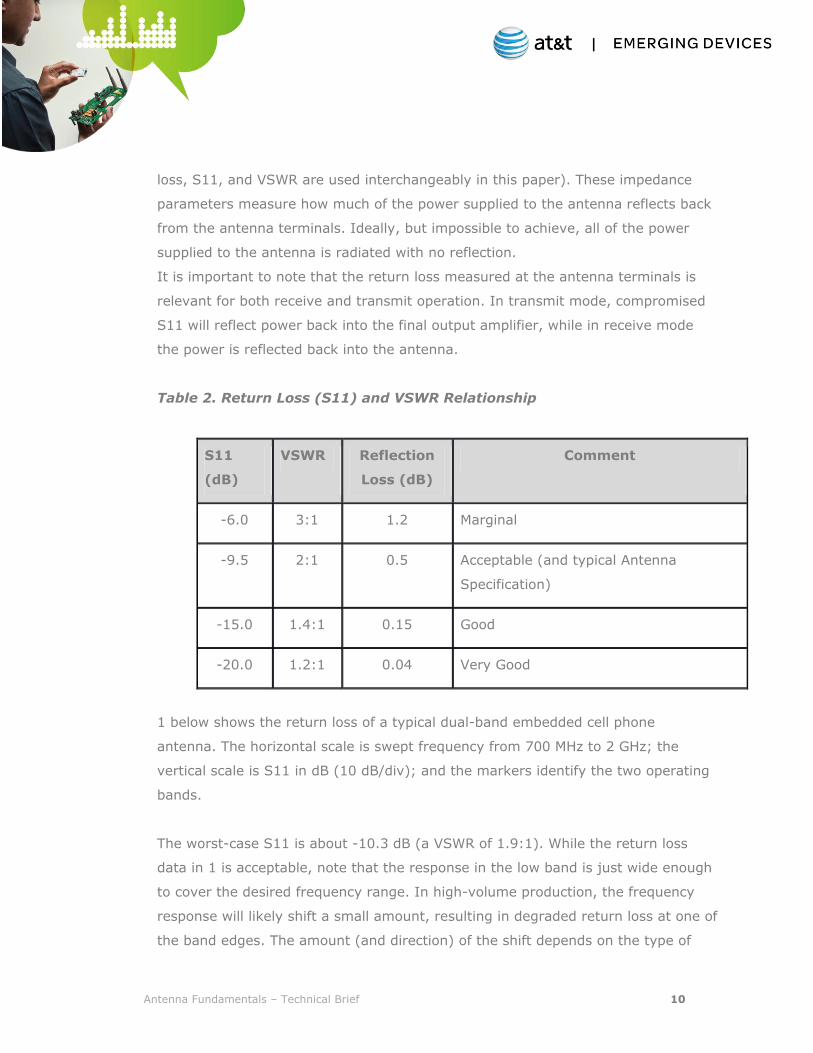
Table 2. Return Loss (S11) and VSWR Relationship
S11
(dB)
VSWR Reflection
Loss (dB)
Comment
-6.0 3:1 1.2 Marginal
-9.5 2:1 0.5 Acceptable (and typical Antenna
Specification)
-15.0 1.4:1 0.15 Good
-20.0 1.2:1 0.04 Very Good
1 below shows the return loss of a typical dual-band embedded cell phone
antenna. The horizontal scale is swept frequency from 700 MHz to 2 GHz; the
vertical scale is S11 in dB (10 dB/div); and the markers identify the two operating
bands.
The worst-case S11 is about -10.3 dB (a VSWR of 1.9:1). While the return loss
data in 1 is acceptable, note that the response in the low band is just wide enough
to cover the desired frequency range. In high-volume production, the frequency
response will likely shift a small amount, resulting in degraded return loss at one of
the band edges. The amount (and direction) of the shift depends on the type of
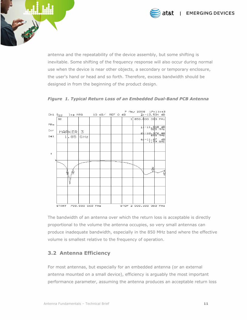
Antenna Fundamentals – Technical Brief 11
antenna and the repeatability of the device assembly, but some shifting is
inevitable. Some shifting of the frequency response will also occur during normal
use when the device is near other objects, a secondary or temporary enclosure,
the user's hand or head and so forth. Therefore, excess bandwidth should be
designed in from the beginning of the product design.
Figure 1. Typical Return Loss of an Embedded Dual-Band PCB Antenna
The bandwidth of an antenna over which the return loss is acceptable is directly
proportional to the volume the antenna occupies, so very small antennas can
produce inadequate bandwidth, especially in the 850 MHz band where the effective
volume is smallest relative to the frequency of operation.
3.2 Antenna Efficiency
For most antennas, but especially for an embedded antenna (or an external
antenna mounted on a small device), efficiency is arguably the most important
performance parameter, assuming the antenna produces an acceptable return loss
Antenna Fundamentals – Technical Brief 12
over the band of interest. Efficiency is simply a measure of what portion of the
power supplied to the antenna, including any reflection loss, is actually radiated by
the antenna.
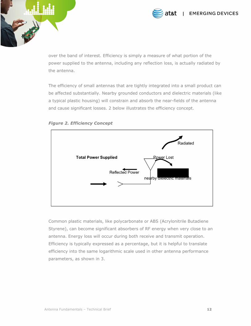
The efficiency of small antennas that are tightly integrated into a small product can
be affected substantially. Nearby grounded conductors and dielectric materials (like
a typical plastic housing) will constrain and absorb the near-fields of the antenna
and cause significant losses. 2 below illustrates the efficiency concept.
Figure 2. Efficiency Concept
Common plastic materials, like polycarbonate or ABS (Acrylonitrile Butadiene
Styrene), can become significant absorbers of RF energy when very close to an
antenna. Energy loss will occur during both receive and transmit operation.
Efficiency is typically expressed as a percentage, but it is helpful to translate
efficiency into the same logarithmic scale used in other antenna performance
parameters, as shown in 3.
Antenna Fundamentals – Technical Brief 13
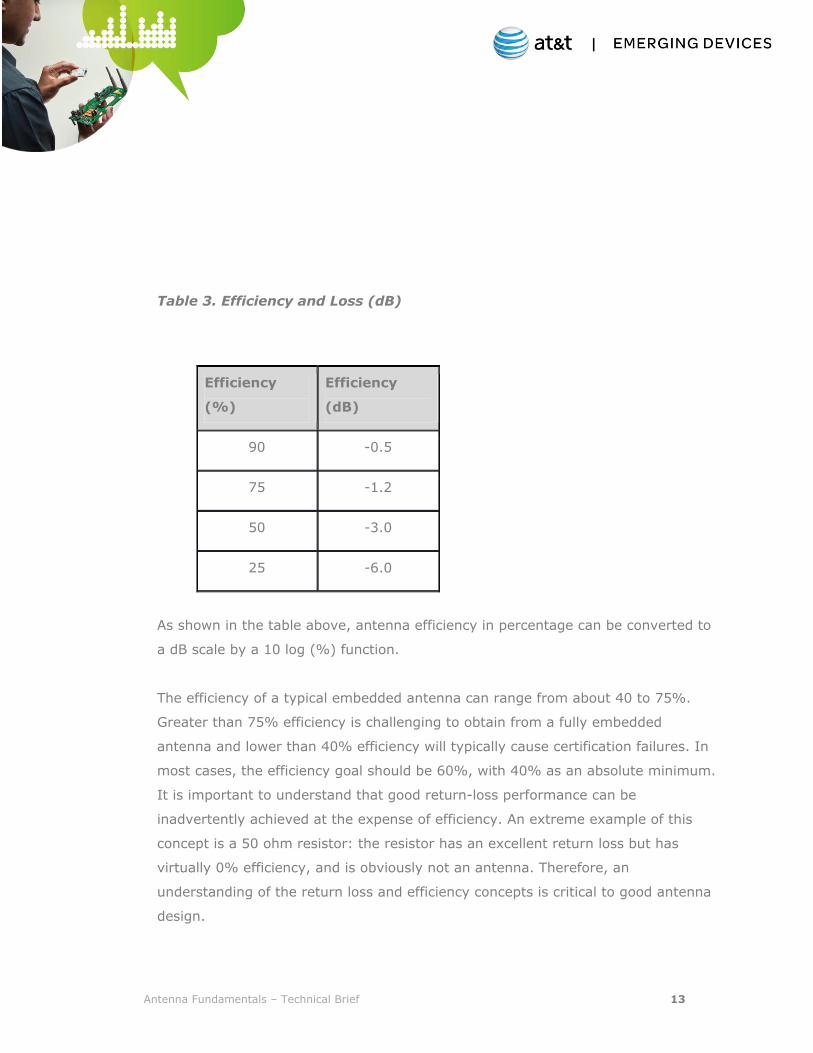
Table 3. Efficiency and Loss (dB)
Efficiency
(%)
Efficiency
(dB)
90 -0.5
75 -1.2
50 -3.0
25 -6.0
As shown in the table above, antenna efficiency in percentage can be converted to
a dB scale by a 10 log (%) function.
The efficiency of a typical embedded antenna can range from about 40 to 75%.
Greater than 75% efficiency is challenging to obtain from a fully embedded
antenna and lower than 40% efficiency will typically cause certification failures. In
most cases, the efficiency goal should be 60%, with 40% as an absolute minimum.
It is important to understand that good return-loss performance can be
inadvertently achieved at the expense of efficiency. An extreme example of this
concept is a 50 ohm resistor: the resistor has an excellent return loss but has
virtually 0% efficiency, and is obviously not an antenna. Therefore, an
understanding of the return loss and efficiency concepts is critical to good antenna
design.
Antenna Fundamentals – Technical Brief 14
3.3 Antenna Radiation Pattern and Polarization
An antenna is a physical device that radiates energy, almost always with some
directional dependence. Even an omni-directional antenna will have one or two
narrow directions where there is a reduction or a null in the radiated energy. The
energy leaving an antenna is also polarized – meaning that the electric field is in a
particular orientation.
Theoretically, for efficient transfer of energy between two antennas, their
respective radiation patterns must be optimized in the correct direction and the
antennas must be polarized with the same orientation. However, in the real world,
where line of sight (LOS) between two antennas rarely exists, and at frequencies
above about 500 MHz, objects in the path between the antennas (walls, structures,
people, terrain, etc.) can substantially alter both the effective radiation patterns
and the polarization. These scattering effects on the radiation pattern and
polarization are random, uncontrollable, and typically change continuously with
time, relative antenna position and orientation. Even if a device is located in a
fixed position, polarization will typically change with time due to movement of
nearby objects. As a result, while some general attention must be paid to radiation
pattern shape and antenna polarization, these parameters can be optimized for a
particular situation in only a general way.
For example, when a 2.4 GHz ISM band wireless link is operating indoors, antenna
polarization can largely be ignored because reflections and multipath completely
randomize the polarization at any given point in space. Once beyond LOS, even
just a few meters from an antenna, the original polarization is completely lost.
Most wireless devices (in the category under discussion in this paper) have small
antennas mounted on small ground planes. The physics of antenna radiation
stipulate that radiation from these structures will not have narrow directional lobes
Antenna Fundamentals – Technical Brief 15
with high gain. In other words, the radiation patterns will generally not have
directions where the gain exceeds +3 dBi and will also not have directions with
very little radiation. The radiation patterns will be generally omni-directional
because high-gain, and the narrow radiation lobes of associated with high-gain,
require electrically large structures to form array-like antenna structures. Of
course, there will be nulls in the radiation patterns in various directions but the
nulls will usually be polarization dependent. If a null exists in a particular
polarization, it will not exist in the orthogonal polarization.
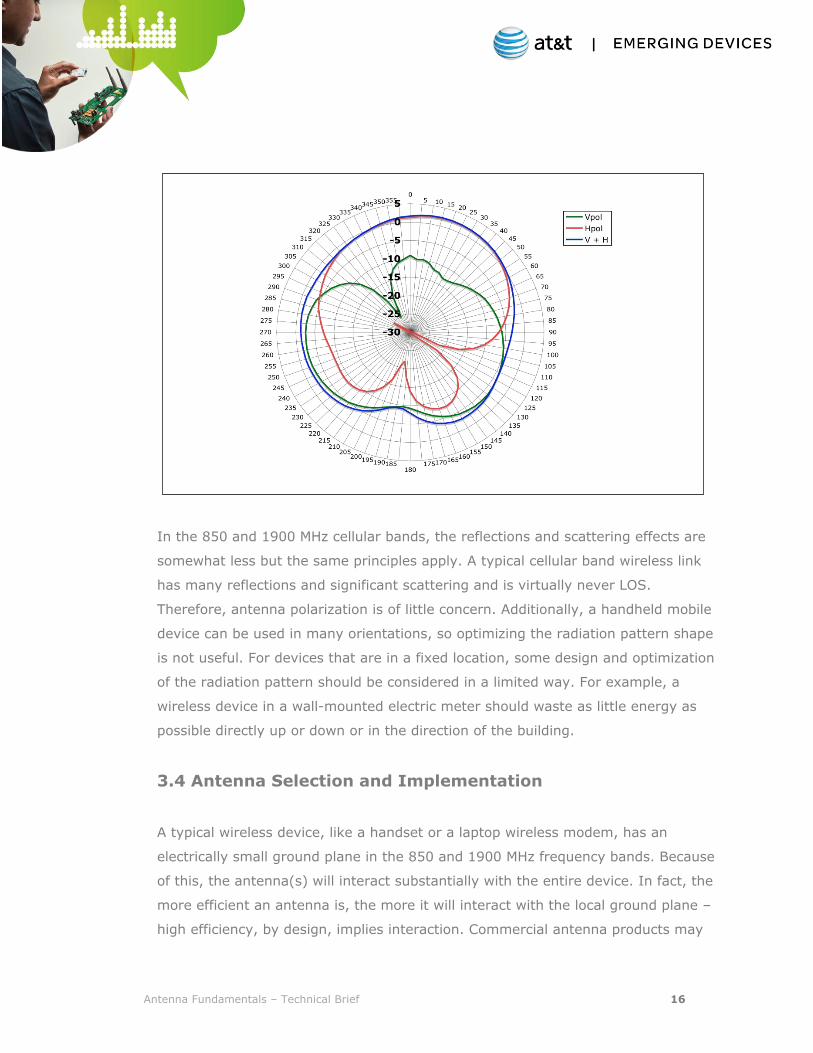
Figure 3 below shows a typical embedded antenna radiation pattern. The three
traces are antenna gain in vertical and horizontal polarization (in dB relative to an
isotropic radiator, or dBi) and vertical plus horizontal (the total gain). While this
pattern would not normally be considered “omni”, it is acceptable from a gain and
overall coverage perspective. It must also be understood that the radiation pattern
shown below is just one “slice” from the three dimensional sphere surrounding any
device. The features of the pattern (nulls, polarization, maximum gain) will often
change dramatically with the angle in what is conventionally called the “pattern
cut”.
Figure 3 . Typical Embedded Antenna Radiation Pattern
Antenna Fundamentals – Technical Brief 16
In the 850 and 1900 MHz cellular bands, the reflections and scattering effects are
somewhat less but the same principles apply. A typical cellular band wireless link
has many reflections and significant scattering and is virtually never LOS.
Therefore, antenna polarization is of little concern. Additionally, a handheld mobile
device can be used in many orientations, so optimizing the radiation pattern shape
is not useful. For devices that are in a fixed location, some design and optimization
of the radiation pattern should be considered in a limited way. For example, a
wireless device in a wall-mounted electric meter should waste as little energy as
possible directly up or down or in the direction of the building.
3.4 Antenna Selection and Implementation
A typical wireless device, like a handset or a laptop wireless modem, has an
electrically small ground plane in the 850 and 1900 MHz frequency bands. Because
of this, the antenna(s) will interact substantially with the entire device. In fact, the
more efficient an antenna is, the more it will interact with the local ground plane –
high efficiency, by design, implies interaction. Commercial antenna products may

Antenna Fundamentals – Technical Brief 17
be described as having “immunity to nearby materials” but this is generally either
untrue or the antenna has low efficiency. Directional antennas (like a microstrip
patch) and antennas using new band-gap technologies can have limited interaction
with nearby materials but these are unusual situations. Most often, the integrated
antenna is a structure that includes the product within its near field, so interaction
is inevitable.
The antenna/ground plane interaction creates a complex situation where the
antenna impedance (and impedance bandwidth), overall efficiency, and radiation
pattern all depend heavily on the characteristics of the entire device.
Intelligent implementation of the antenna must be holistic in approach, involving
the entire device and considered from the very beginning of the product design. As
Larry Zibrik of Sierra Wireless told us during an interview for this paper “An OEM
must realize that, almost without exception, the industrial design of the device will
be impacted by the antenna design. Understanding and anticipating this fact from
the very beginning of the design process is critical to success.” For obvious
reasons, the conductive parts of the device have the largest influence on the
antenna, but non-conductive components (enclosure, PCBs, etc.) will also affect
antenna design and performance.
Manufacturers of radio modules are an excellent source of antenna element design
or selection and antenna location within the device. These manufacturers have
likely seen similar devices and are therefore familiar with both the electrical and
mechanical design issues, as well as the manufacturing issues of particular
antennas. Obtaining antenna design and implementation advice from the radio
module manufacturers is worth the effort and cost involved, especially considering
the very high costs associated with a product re-design after the failure of FCC
regulations, PTCRB, or carrier requirements.
The following sections discuss antenna types and configuration. The discussion
assumes that that the antenna is a dual-band device.
4.1 Embedded vs. External

Antenna Fundamentals – Technical Brief 18
Antennas for wireless devices can be completely embedded inside the product or
can be mounted external to the product housing. Each implementation has its
particular advantages and disadvantages.
4.1.1 External Antennas
In the following discussion, an external antenna is assumed to be a short vertical
wire or a trace (or traces) on a PCB, typically encased in a plastic housing.
An external antenna is external to the main housing of the device, is connected to
the device in one place (often with an RF connector), and generally is
perpendicular to the largest dimension(s) of the device.
Dipoles and monopoles are typical external antennas, with a size of 1/2 and 1/4
wavelength, respectively. These antennas, if designed correctly, provide excellent
performance. External antennas achieve high efficiency and have, in general,
better immunity to the self-generated noise of the product, although any antenna
is susceptible to external noise.
While external antennas can provide superior performance, there are significant
disadvantages: susceptibility to damage, additional manufacturing cost, and
potential performance degradation due to the user's interaction with the exposed
antenna. While external antennas clearly have their uses, they are generally not
recommended for the typical modern hand-held wireless device.
4.1.2 Embedded Antennas
An embedded antenna is any antenna that lies completely within the device
housing. It is most typically mounted parallel to the largest dimension(s) of the
device. An embedded antenna may or may not use connectors.
Embedded antennas may be printed on the edge of a PCB, can be a separate sheet
metal part (or wire) that is soldered to a PCB, or can be a hybrid of these
techniques. The antenna can be sprayed or painted (using conductive paint) on the
plastic housing of the device. An embedded antenna can also be created from
conductive parts of the device structure. Very small “chip” antennas that can be

Antenna Fundamentals – Technical Brief 19
placed on a PCB like a standard circuit component are available, although these
antennas suffer considerably in efficiency and should be used with caution. AT&T
discourages the use of dielectric chip antennas on the AT&T network.
Printed antennas are strongly influenced by the PCB substrate material properties,
namely the dielectric constant (DK) and loss tangent, often called dissipation factor
(DF). The PCB substrate material will reduce the resonant length of the antenna
which will result in a reduction of the usable bandwidth.
Additionally, the PCB substrate will introduce a loss mechanism and reduce the
antenna efficiency. PCB substrate and plastic housing losses can substantially
reduce embedded antenna efficiency and it is important to remember, as noted
earlier in the efficiency discussion, that normally low-loss plastics can introduce
significant loss when very close to and around an embedded antenna.
4.2 Antenna Type and Location
In this paper, the type of antenna discussed is limited to dipoles and monopoles
(usually external antennas), the inverted-F (and its many variants), and the
microstrip patch antenna. Other basic antenna elements, like the loop antenna and
the slot antenna, have only limited applications, especially as embedded antennas.
Detailed design information for each antenna type is beyond the scope of this
paper but general design guidelines and common mistakes will be discussed.
While a properly designed external antenna will generally provide the best
performance in almost all situations, today's product design constraints often
completely eliminate the external antenna as an option. As such, external antenna
implementation will be discussed from only one perspective - orientation. Simply
put, the orientation of a dipole or monopole type external antenna must be
generally perpendicular to the local ground plane of the wireless device. A dipole or
monopole antenna that is positioned parallel to (and within about 30 mm of) the
local RF ground plane, will have degraded return loss and compromised efficiency.

Antenna Fundamentals – Technical Brief 20
This point cannot be emphasized enough as it is a common mistake. The mounting
of dipoles and monopoles parallel to the local RF ground plane must be avoided.
One additional point with respect to external is that when selecting a commercially
available external antenna, it is critical to verify that the antenna performance
meets the manufacturer's specifications. Most electronic components available
today have detailed and accurate specifications. However, this is generally not true
of off-the-shelf antennas. Purchasing from a known or respected supplier and/or
performing independent testing are the only ways to ensure that the antenna
conforms to what the datasheet claims. In the world of commercial antennas for
small devices, especially at the low end of the cost scale, incorrect and misleading
datasheets are much more common than one might expect.
4.2.1 Embedded Antenna Type
Inverted-F Style Antenna (IFA)
The inverted-F antenna is the most common embedded antenna in use today in
wireless devices in the 900 MHz to 6 GHz frequency range. It can be formed in a
multitude of ways, has excellent multi-band capability, and can be made highly
efficient. Originally designed in the early 1960s as a single-band conformal UHF
antenna for use on aircraft, the inverted-F has evolved into a low-profile multi-
band antenna than can be integrated into today’s small and complex product
designs.
In its most basic form, the inverted-F is a quarter-wave long conductor parallel to
and within a few mm of the RF ground plane, grounded at one end, and has a 50-
ohm feedpoint close to the grounded end. The quarter-wave conductor can be a
thin wire, a trace on a PCB, or a 3D surface and can be straight or folded into
complex shapes. The 3D version is commonly called a PIFA, or Planar Inverted-F
Antenna. An IFA can be referred to as a two-dimensional antenna while the PIFA
would be a three-dimensional antenna. The following photos show sheet metal and
Antenna Fundamentals – Technical Brief 21
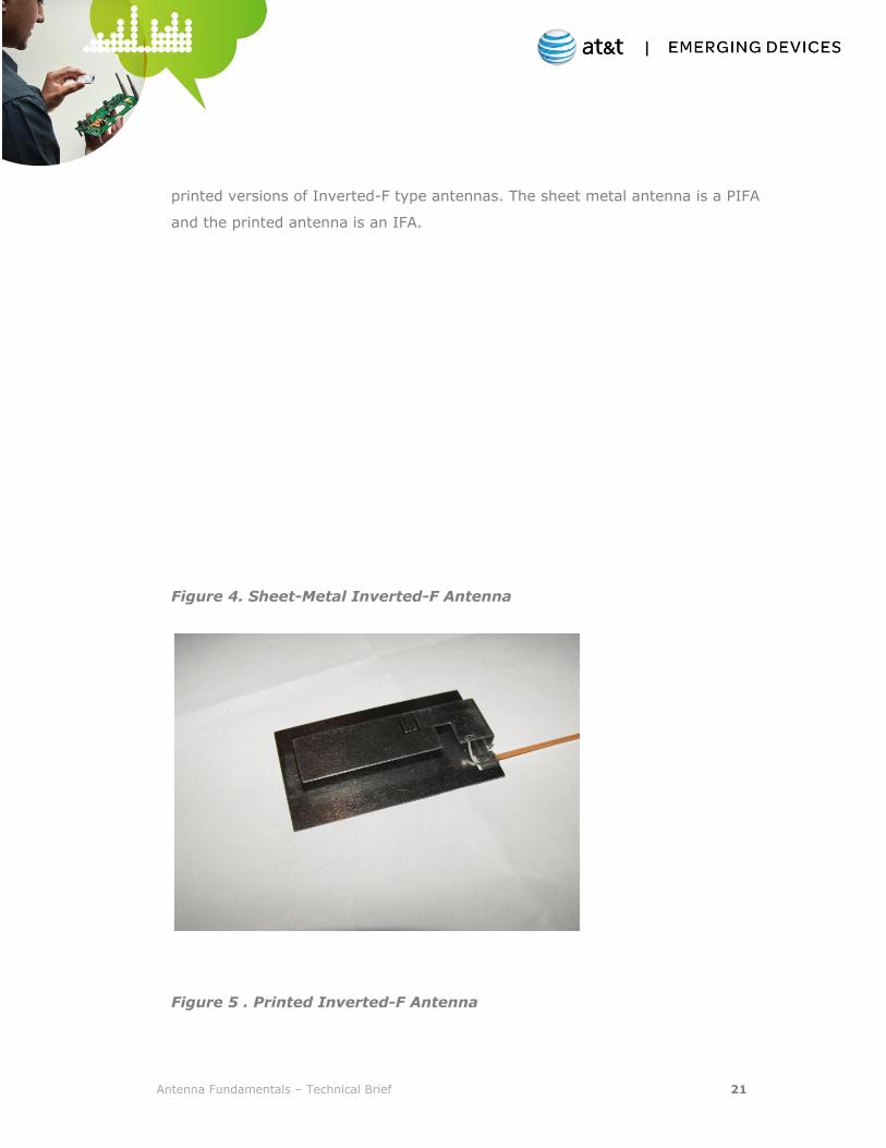
printed versions of Inverted-F type antennas. The sheet metal antenna is a PIFA
and the printed antenna is an IFA.
Figure 4. Sheet-Metal Inverted-F Antenna
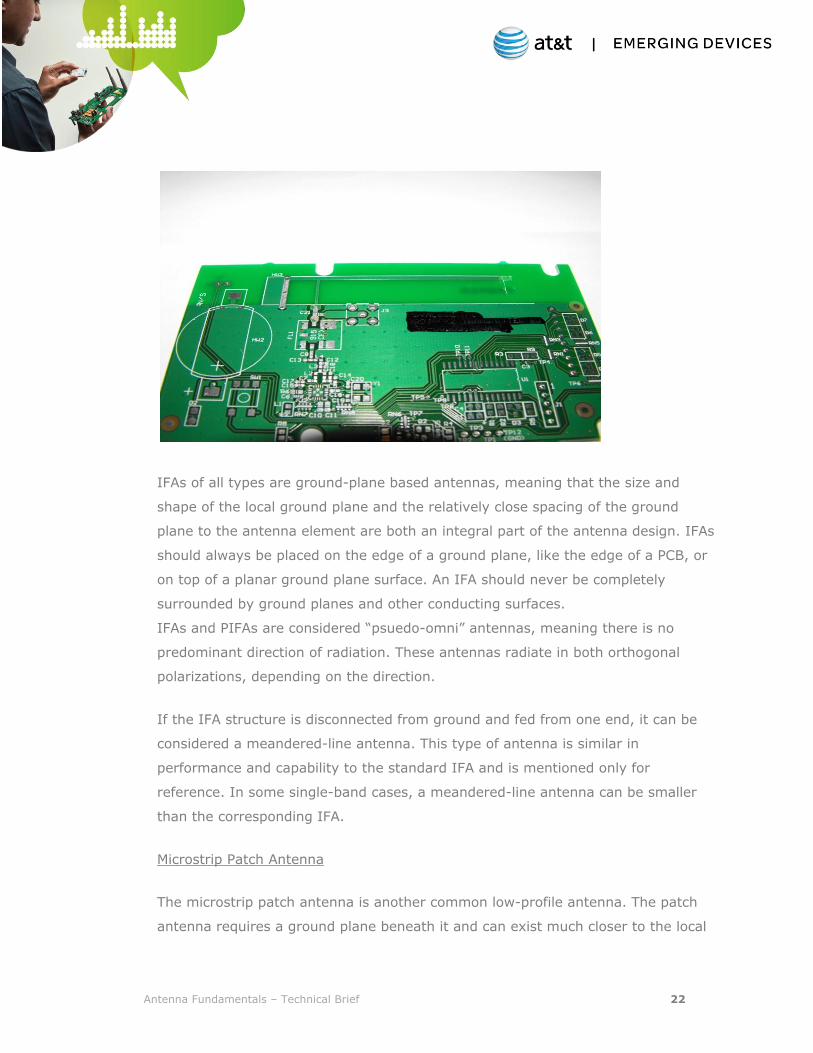
Figure 5 . Printed Inverted-F Antenna
Antenna Fundamentals – Technical Brief 22
IFAs of all types are ground-plane based antennas, meaning that the size and
shape of the local ground plane and the relatively close spacing of the ground
plane to the antenna element are both an integral part of the antenna design. IFAs
should always be placed on the edge of a ground plane, like the edge of a PCB, or
on top of a planar ground plane surface. An IFA should never be completely
surrounded by ground planes and other conducting surfaces.
IFAs and PIFAs are considered “psuedo-omni” antennas, meaning there is no
predominant direction of radiation. These antennas radiate in both orthogonal
polarizations, depending on the direction.
If the IFA structure is disconnected from ground and fed from one end, it can be
considered a meandered-line antenna. This type of antenna is similar in
performance and capability to the standard IFA and is mentioned only for
reference. In some single-band cases, a meandered-line antenna can be smaller
than the corresponding IFA.
Microstrip Patch Antenna
The microstrip patch antenna is another common low-profile antenna. The patch
antenna requires a ground plane beneath it and can exist much closer to the local
Antenna Fundamentals – Technical Brief 23
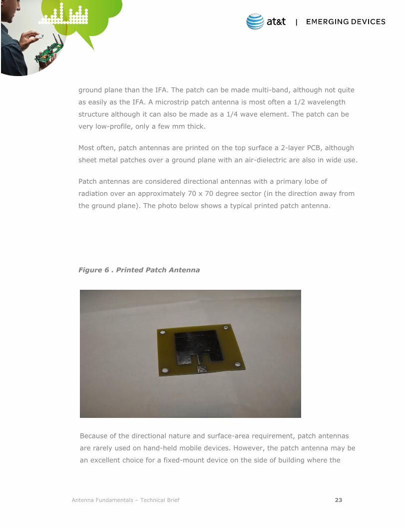
ground plane than the IFA. The patch can be made multi-band, although not quite
as easily as the IFA. A microstrip patch antenna is most often a 1/2 wavelength
structure although it can also be made as a 1/4 wave element. The patch can be
very low-profile, only a few mm thick.
Most often, patch antennas are printed on the top surface a 2-layer PCB, although
sheet metal patches over a ground plane with an air-dielectric are also in wide use.
Patch antennas are considered directional antennas with a primary lobe of
radiation over an approximately 70 x 70 degree sector (in the direction away from
the ground plane). The photo below shows a typical printed patch antenna.
Figure 6 . Printed Patch Antenna
Because of the directional nature and surface-area requirement, patch antennas
are rarely used on hand-held mobile devices. However, the patch antenna may be
an excellent choice for a fixed-mount device on the side of building where the
Antenna Fundamentals – Technical Brief 24
radiation from a more omni-directional antenna would be wasted in the direction
of the building.
4.3 Common Implementation Mistakes
The following discussion is on typical antenna implementation problems and
mistakes. This is not a comprehensive list but simply a discussion of the most
common issues.
Dipole or Monopole Parallel to Ground Plane
As discussed earlier, a commercial dipole or monopole style antenna is often
mounted close to and parallel to a ground plane. These antennas must be mounted
perpendicular (or within about 25 deg of perpendicular) to the local ground plane.
It makes little difference if the edge of the ground plane or a surface of the plane
is used. Both impedance and efficiency can suffer dramatically from improper
mounting.
Antenna in Conductive "Window"
Sometimes a product is housed in a metal enclosure, for functional and/or
aesthetic reasons. If the antenna is not external to the enclosure, the typical
solution is to open up a "window" in the metal enclosure. This idea appears simple
and straightforward but this approach is usually disastrous. An antenna in a
conductive window, even if tuned correctly for this situation, will have seriously
degraded efficiency. Efficiency degradation of up to 15 dB has been measured on
otherwise efficient antennas that have been exposed in a window within a
conducting surface. In general, windows for antennas should be avoided
completely.
Printed Antenna Surrounded by Ground Plane
Printed antennas should be placed on the periphery of the PCB under
consideration. Ideally, the antenna should have three edges exposed (at one end

Antenna Fundamentals – Technical Brief 25
of the PCB). If this is not possible, the printed antenna should be placed in the
corner of the board so two sides are exposed. Surrounding the printed antenna on
three sides, or even worse, on all 4 sides, will degrade performance substantially.
Antenna Impedance not Validated in Product
Commercial antennas, either external or embedded, often have return loss
specifications that have been measured by the manufacturer. While this is useful
data, the antenna impedance must be validated with the antenna installed in the
product, with all of the surrounding materials (conductors and non-conductors) in
place, and with all components installed on the PCB. Even the small details of a
plastic enclosure can influence the impedance of the antenna.
Antenna Too Close to Digital Noise Source
Electrical noise generated by the circuitry of the device can enter the antenna
directly and result in poor or intermittent performance, and failure at the PTCRB
test lab. Care should be taken to locate the antenna as far as possible from noise
sources.
Antenna Placed In Poor Location with regard to Body Effects
If the product is to be hand-held or otherwise in contact with the human body,
remember that interaction with the human body will introduce power loss external
to the product in both receive and transmit operation. As a separate issue,
interaction with the human body will also cause de-tuning of the antenna. Both of
these effects seriously degrade performance. Testing should be performed to
properly quantify the effects of the human body.
4.4 Antenna Design and Implementation Assistance
There are several approaches available to achieve the intended antenna
implementation and performance. The three primary approaches are:

Antenna Fundamentals – Technical Brief 26
1) Commercial off-the-shelf antenna element(s).
2) Reference design (typically supplied by radio module vendor).
3) Custom antenna design (usually requiring an antenna-design consultant).
Most industry experts recommend approaches 2 and 3 with the caveat that using a
reference design should be considered a “semi-custom” design – meaning that
while the reference design may be correct, some adjustments to the design will
likely be required in a new device.
When evaluating a reference design, it is important to know exactly what the
reference design represents: actual measured data from a working antenna, or
perhaps just simulations from antenna-design software. Simulations are useful but
often need substantial adjustments once implemented in hardware. A reference
design, no matter how straightforward, should never be implemented without
confirmation (by measurement) of its performance parameters. During a
discussion with David Bissonette of 7 Layers, Inc., he echoed the issues above and
added “For most OEMs, obtaining antenna design services at the beginning of the
product design phase is critical to the product success. Although qualified design
help can be expensive, the cost of a substantial product re-design – at the
moment when the device should be starting volume production – is much higher.”
As briefly discussed earlier, commercial antennas often have inaccurate or
misleading specifications. Remember that the antenna cannot be considered in
isolation because the entire device defines the antenna impedance, bandwidth,
and efficiency. Therefore, a specification or datasheet is of only limited usefulness.
Off-the-shelf antennas can be excellent solutions but only if implemented as
carefully as a full-custom antenna design.
Some radio module vendors and certified test labs are now offering antenna
design assistance at whatever technical level is required. The expertise provided
by these vendors should be used whenever possible.
4.5 Antenna System Issues
Antenna Fundamentals – Technical Brief 27
This section discusses antenna issues, including connecting the antenna, self-
interference and co-existence with other wireless technologies.
4.5.1 Connecting the Antenna
The antenna is one critical component of the radio system or, more precisely, the
radio system front-end. The front-end is comprised of the antenna, any
components (like filters, amplifiers, switches) between the antenna and the RF
chain of the radio, and the connections between the various components. It is
critical that the various connections are made with controlled impedance
structures. These structures can be coaxial cable, controlled impedance PCB traces
like microstrip or stripline, spring-loaded pogo pins or spring fingers, flex circuits
with controlled impedance lines, and so forth. Attention must be paid to the
various interfaces between these structures and the antenna and circuit terminals.
Circuit components and antennas that are well-matched when measured in
isolation can suffer from impedance-matching issues when used in combination
with poorly designed interconnects. For example, spring fingers have become
common in cellular handsets (to connect to the antenna mounted in the housing)
and work quite well. However, during the design process, both the impedance and
noise-pickup potential of the fingers must be taken into account.
Another good example of the front-end interconnect issue is the use of a filter
which utilizes antenna element as one termination. Very often, antennas in actual
devices may have VSWRs of 3:1 (possibly higher), especially at the band edges.
Most reflective-type filters rely on good impedance matching to provide the
specified filtering and a VSWR of 3:1 is typically not adequate to properly
terminate the filter component. Some tuning, external to the antenna and filter,
may be required to insure that the filter is operating correctly. An improperly
terminated filter can introduce substantial insertion loss in addition to a distorted
filter response.
Cables and PCB traces will introduce losses (in both transmit and receive) and
must be carefully considered. Cables and traces create opportunities for noise to
enter the system at the especially vulnerable point of the receiver input. Care
must be taken to route all interconnects away from or around noise sources.

Antenna Fundamentals – Technical Brief 28
The mechanical and electrical reliability of interconnects is also important. Normal
“wear and tear” can degrade the integrity of the interconnect system and produce
degraded device performance and even outright device failure.
4.5.2 Self-Interference
Self-interference is created when the emissions from a device's own internal
circuitry enter the antenna (or the radio front end) and raise the receiver noise
floor, thereby degrading the receiver sensitivity. Larry Zibrik told us that “self-
interference, due to poor antenna selection or implementation, is the single
biggest challenge to successful device certification”.
The effect of self-interference may be just a few dB, and perhaps go unnoticed, or
it can result in a sensitivity reduction of 10 to 20 dB or even higher and
dramatically reduce the operating range and performance of the device. Self-
interference issues may delay or even cancel a product launch.
The primary noise source is the digital circuitry – usually the processor (or
processors) and the system memory. Other noise sources are possible, of course,
but the processor, its associated clocks, high-speed memory, and display and
graphics processors are very often the highest in level and produce the widest
range of frequencies. It is also critical to realize that a device that displays
emissions low enough to pass the FCC regulations can still suffer from self-
interference. In most cases, the receiver sensitivity is much lower than FCC test
limits.
Eliminating self-interference is a complex subject and beyond the scope of this
paper but the following guidelines should be followed:
1) Shield the digital electronics with PCB-mounted shield cans. Rarely is
some shielding of the digital electronics not required.
2) Place the antenna(s) as far from the noise sources as possible.
3) Route the antenna interconnect(s) away from the noise sources.

Antenna Fundamentals – Technical Brief 29
4) If non-shielded antenna interconnects are used (like spring fingers or pogo
pins) give these interfaces special attention with regard to exposure to noise
sources.
Unfortunately, it is difficult or impossible to completely understand the full extent
of any self-interference until a device is actually operating in the form-factor it will
ultimately use. Therefore, it is critical to design shielding and other self-
interference mitigations into the device from the very beginning and then to
measure and analyze the self-interference situation as early as possible to avoid
problems with receiver sensitivity during PTCRB testing.
4.5.3 Co-existence with Other Wireless Technologies
Today, wireless devices often have multiple transceivers, operating in various
bands: Wi-Fi (possibly with Multiple Input Multiple Output or MIMO), Bluetooth,
ZigBee, GPS, 915 MHz ISM, other Part 15 devices – all of which have antennas
associated with them. On a small device, antennas must sometimes be placed very
close to one another. Most of these wireless technologies will transmit their own
intentional signals and also generate noise, both of which can interfere with the
cellular band reception.
Conversely, the cellular band transmitter generates large-amplitude signals (most
often the largest signals a device produces) that can overwhelm a nearby receiver
and cause severe distortion. The transmitter output of the typical cellular radio is
high enough to interfere with a nearby Wi-Fi or GPS receiver, even though the
frequency bands are separated by hundreds of MHz.
As with self-interference, co-existence issues are difficult to quantify before a
product is assembled and operating so good design decisions early in the process
are important – another reason to obtain qualified advice as early in a project as
possible. Co-existence issues are also an opportunity for the radio module
manufacturer to provide advice and lessons learned from experience.
5. Antenna Performance Measurements

Antenna Fundamentals – Technical Brief 30
To successfully design (or purchase) and then integrate an antenna into a wireless
device, a number of measurements must be made to quantify the antenna
performance in the actual product. Simply relying on a manufacturer’s datasheet,
bench measurements of an antenna in isolation, or an un-verified reference design
will likely result in poor performance in the device.
Impedance and Antenna Bandwidth
As discussed above, antenna impedance is typically measured as return loss or
VSWR. The equipment used to measure this parameter is a Network Analyzer. The
impedance (and the bandwidth over which the impedance is acceptable) must be
measured with the antenna installed in the device with all components installed.
The impedance measurement often requires special fixtures and assemblies to
allow access to the antenna terminals. It is not uncommon that the antenna
requires some small tuning adjustments when the device is finally fully assembled.
At this stage, if the initial design was well done, most embedded antennas are
often quite easily tuned with small changes to the PCB layout or sheet metal part,
and/or with the addition of passive components on the antenna or the radio PCB.
Gain and Radiation Patterns
Calibrated measurements of antenna gain and radiation patterns are made in an
Anechoic Chamber. The anechoic environment eliminates all reflections and allows
precise and repeatable measurements to be made. The device under test is
typically rotated 360 degrees in multiple orientations to determine the shape of
the radiation pattern from many different directions. Reference antennas are used
as calibrated gain standards.
As with impedance measurements, gain and radiation patterns should be
measured using a complete product.
Efficiency Measurements
As mentioned earlier, efficiency may be the single most important parameter to be
measured, especially for an embedded antenna which can have degraded

Antenna Fundamentals – Technical Brief 31
efficiency due to its tight integration with the device. Efficiency can be calculated
from the calibrated gain and radiation pattern measurement but this can be a
time-consuming effort.
Within the last 10 years, a new type of efficiency measurement tool has become
available – sometime referred to as a “3D Chamber”. The most common
manufacturer of this tool is Satimo. The 3D Chamber uses a circular array of test
antennas (measuring energy in two orthogonal polarizations) and a rotating table
to quickly measure the total energy generated by the antenna under test. The
resulting total efficiency measurement is accurate, repeatable and can be used to
compare various antenna topologies quickly.
6. Antenna Issues Related to Product Certification
Successful certification of a wireless device requires compliance with FCC
regulations, PTCRB conformance test requirements, and AT&T specifications. FCC
regulations are primarily concerned with radiated emissions from the device (both
intended and un-intended) while the PTCRB conformance testing is primarily
intended to verify the proper RF parametric operation in a conducted RF
environment. AT&T's device requirements focus on device functionality and
interoperability with the AT&T network. In addition, AT&T requires the
measurement of a device's Total Radiated Power and Total Integrated Sensitivity.
The AT&T TRP and TIS requirements can be obtained upon execution of a non-
disclosure agreement (NDA).
While writing this paper, we wanted to know what kind of antenna issues arose
most commonly during the certification process so we interviewed several experts
from major certification labs. When asked what were the primary antenna-related
reasons for certification failures, Lothar Schmidt of Cetecom Laboratories told us
“The most common antenna-related failures, in order, are high levels of
Antenna Fundamentals – Technical Brief 32
transmitter harmonics, TIS failures due to self-interference, and TRP failures due
to compromised antenna efficiency.”
Failure to meet FCC regulations is rarely an antenna-only issue. The antenna
cannot produce emissions on its own, although the antenna can influence
transmitter harmonic generation that can lead to FCC test failures. Generally, FCC
failures are system related issues which may involve the antenna.
Devices intended for operation on the AT&T network must display high antenna
efficiency and a low level of self-interference in order to meet AT&T's acceptance
criteria. Devices with antennas which fail to meet AT&T's TRP requirements may
not only be inefficient, they may create other problems, such as excessive
harmonic generation from the transmitter. Devices which fail to meet AT&T's TIS
requirements may have an efficient antenna, but the receiver sensitivity is
compromised by self-interference, such as noise entering the antenna from within
the device itself.
In short, the antenna and its complex interaction with the wireless device is part of
every radiated measurement a device is subjected to during the certification
process and will influence the measurement results.
6.1. Using a Certified Radio Module
For obvious reasons, it is important to begin any product design with a radio
module that has already been certified. The certified module, when connected to a
correctly implemented “typical” antenna, will provide acceptable performance in
both receive and transmit modes.
6.2 Transmit Mode Failures
Assuming the radio module is certified and capable of generating the appropriate
amount of RF power, transmit mode failures are typically caused by low antenna
efficiency or degraded return loss (which appears as low efficiency due to the
Antenna Fundamentals – Technical Brief 33
reflected power). Unfortunately, improving poor antenna efficiency at the late
stage of development where PTCRB testing takes place is very difficult and will
almost certainly require a significant re-design of the product enclosure and
antenna type. Poor efficiency results from either the choice of antenna or its
position and orientation within the product, both of which are fundamental design
parameters.
It is possible that the efficiency of the antenna element itself is acceptable but the
antenna has become mis-tuned, either in the design process or during final
assembly of the device. In this case, restoring the performance can often be quite
simple by slightly adjusting the antenna geometry. However, it is critical to
understand exactly what the source of the failure is. Simply improving the tuning
of an inherently low-efficiency antenna will not yield good results.
6.3 Receive Mode Failures
Receive-mode failures of a device with a module that has acceptable receive
sensitivity can be caused by poor antenna efficiency, self-interference or a
combination of the two. As is the case with transmit-mode failures, improving
antenna efficiency at this stage is very difficult, but re-tuning a mis-tuned antenna
is often easily done, even at this late stage of product development.
Resolving a self-interference issue at the PTCRB testing stage is possible (although
still challenging) and will likely require changes to the hardware. Analyzing the
extent of the issue is complex and requires special test equipment and careful
analysis. Additionally, antenna tuning and self-interference can sometimes be
interactive – the antenna impedance may influence the level of self-interference.
For these reasons, taking self-interference into account early in the design phase is
critical.
6.4 Harmonic Generation Failures

Antenna Fundamentals – Technical Brief 34
A failure to meet FCC regulations or PTCRB radiated-spurious-emissions-
conformance requirements due to a level of harmonic energy generated by the
device is often blamed on the antenna. In truth, the antenna can often influence
the level of the harmonics but does not generate these signals. An antenna almost
never has gain at the harmonics of the intended band of operation. Provided the
radio has acceptable harmonic performance, excessive harmonic generation is
typically an interaction between the impedance of the antenna and the impedance
of the final stage of the transmitter.
The antenna is designed to have acceptable impedance in the bands of use.
Outside of these bands, the impedance is usually uncontrolled (and often
unknown). Unusual or unanticipated impedance conditions can sometimes raise the
harmonic levels of a Tx power amplifier by 10 or even 20 dB. As with other
failures, the out-of-band impedance of the antenna is difficult to change at the
regulatory or conformance test phase. Often, filters between the antenna and
transmitter are added as a last resort, but these components have their own
impedance issues and can often reduce one harmonic while raising the level of
another.
Therefore, as early in the project as possible, the antenna and transmitter should
be tested together with harmonic generation in mind. It is very difficult to design
or purchase an antenna that has a specific impedance at each potential transmitter
harmonic. Approaching the issue in this way will not yield good results. Instead,
the power levels of the harmonics should be measured as soon as it is practical to
do so, when mitigation steps can be readily taken to reduce individual failures.
6.5 Device Pre-Testing
Most radio-module vendors offer some limited pre-testing of the radio and antenna
as a system in their own laboratories. While these facilities can vary widely in
accuracy and repeatability, they should be used if available. Very often, a radio
vendor will be familiar with the issues that their particular module may have when
Antenna Fundamentals – Technical Brief 35
used with a particular type of antenna and early testing related to these issues will
be useful.
The test results should be evaluated carefully as radio vendors’ test facilities are
usually not certified and may have limitations such as inaccuracies, calibration
issues, and incomplete tests. In short, this is useful data to have during product
development, but it is not a substitute for certified lab tests.
7. Conclusion
Successful integration of an antenna into a wireless device depends on the
understanding that the entire device is part of the antenna. The antenna cannot be
added at the end of the design phase; it must be designed in from the very
beginning of the product concept. Fixing antenna problems at the FCC or PTCRB
testing facility is difficult, time-consuming, and expensive.
The primary antenna performance goal must be efficiency. Efficiency is the primary
performance metric of the antenna as a transducer between the radio and the
propagation medium. Antenna tuning and impedance issues can usually be
adjusted to some degree during development. However, an antenna design with
inherently low efficiency, most often because of size constraints imposed by the
industrial design, will often require substantial product re-design for improvement.
Pre-testing of the entire system, especially with transmit harmonics and self-
interference in mind, is critical. Testing as early as possible to identify potential
issues, when they can be more easily fixed, will result in shorter development time
and will ultimately result in substantial cost savings.
Use the knowledge, experience, and if available, the test facilities of the radio
module manufacturer. The radio designers are familiar with the typical
performance problems and test failures related to antennas and can provide
excellent advice from the very beginning of the product design.