Embed Size (px)
Citation preview
INFORMATION DISCOVERY ACROSS
ORGANIZATIONAL BOUNDARIES
THROUGH LOCAL CACHING
By
ANURADHA GASIKANTI
Bachelor of Technology in
Computer Science & Information Technology
Jawaharlal Nehru Technological University
Hyderabad, Andhra Pradesh
2002
Submitted to the Faculty of theGraduate College of the
Oklahoma State Universityin partial fulfillment of
the requirements forthe Degree of
MASTER OF SCIENCEDecember, 2006
ii
INFORMATION DISCOVERY ACROSS
ORGANIZATIONAL BOUNDARIES
THROUGH LOCAL CACHING
Thesis Approved:
Dr. JOHNSON P. THOMASThesis Adviser
Dr. JOHN P. CHANDLER
Dr. DEBAO CHEN
Dr. GORDON EMSLIEDean of the Graduate College
iii
ACKNOWLEDGEMENTS
My sincere thanks are due to my adviser Dr. Johnson Thomas, without his
motivation, encouragement and support; this thesis effort would not have been possible. I
appreciate his time and effort put forth towards my thesis. I am greatly indebted for his
guidance both on personal and professional fronts.
I would also like to thank my committee members Dr. John Chandler and
Dr. Debao Chen for serving on my committee. Their guidance and suggestions are
greatly appreciated.
Grateful appreciation goes to my beloved father Mr. Rama Rao, my mother
Mrs. Saroja and my sister Miss. Arvindha for their endless support, love and
encouragement in all aspects of my life.
Finally I would like to thank my husband Mr. Ravikiran, who stood beside me
with his unfailing and indispensable support. He has been encouraging me all the time to
stay focused on achieving my goal.
iv
TABLE OF CONTENTS
Chapter Page
I. INTRODUCTION………………………………………………………………….. 1
II. LITERATURE REVIEW………………………………………………………….. 5
2.1. Service-Oriented Architecture……………………………………………….. 52.2. Enterprise Service Bus……………………………………………………..... 7
2.2.1. The role of ESB and other SOA components…………………………. 82.2.2. Emerging patterns for integrating different ESBs…………………….. 10
2.3. Extended Service-Oriented Architecture……………………………………. 132.4. UDDI …………………..…………………………………………………… 15
III. PROPOSED APPROACH………………………………………………………. 17
3.1. Virtual Service-Oriented Architecture……………………………………… 193.2. Response Times ……………………………………………………………. 23
IV. SIMULATION MODEL ………………………………………………………... 26
4.1. Simulation Implementation Details …………………………….………….. 264.2. Simulation Results ……………………………………………….……….... 36
4.2.1. Web Service Provider located in Local Organization ……….……...... 374.2.2. Web Service Provider located in Remote Organization ……………... 38
V. CONCLUSION AND FUTURE WORK ……………………………….……….. 46
APPENDIX ………………………………………………………………….……… 48
REFERENCES……………………………………………………………….……... 53
v
LIST OF FIGURES
Figure Page
2.1. Basic Service Oriented Architecture …………………………………………….. 6
2.2. The role of the ESB in a SOA …………………………………………………… 8
2.3. Directly connected ESBs Pattern ……………………………………………….. 11
2.4. Brokered ESB Gateway Pattern ………………………………………………… 12
2.5. Federated ESB Pattern ………………………………………………………….. 13
2.6. Extended SOA protocol ………………………………………………………… 14
3.1. Advertising in the VSOA architecture ………………………………………….. 20
3.2. VSOA architecture protocol ……………………………………………………. 21
4.1. Different Components & its Implementation …………………………………... 27
4.2. NetTool Interface ………………………………………………………………. 30
4.3. Message Flow in Websphere Message Broker ………………………………… 32
4.4. Request flow in ESOA of Message Broker ……………………………………. 34
4.5. Request flow in VSOA of Message Broker ……………………………………. 36
4.6. Roundtrip times vs. no. of requests placed using ESOA ………………………. 39
4.7. Roundtrip times vs. no. of requests placed using VSOA ………………………. 42
4.8. Comparison of ESOA & VSOA models ……………………………………….. 43
vi
LIST OF TABLES
Table Page
3.1. Attributes of different registries in VSOA ……………………………………... 22
4.1. Web Service located in local DB2 using both ESOA & VSOA ……………….. 38
4.2. ESOA – Web Service in remote DB2 ………………………………………….. 41
4.3. VSOA – Web Service available in remote system …………………………….. 41
4.4. Requests processed using Cache in VSOA ……………………………………. 44
1
CHAPTER I
INTRODUCTION
Web Service is a software system designed to support interoperable machine to
machine interaction over a network. Web services are deployed within restricted spaces
of organizations intranets. There is a need for the creation of virtual organizations where
the services offered by one organization should become accessible to other organizations.
It requires opening of IT infrastructures to its participants so that the information can
flow easily within the virtual organization. The main goal of a Service-Oriented
Architecture (SOA) is to bring the uses of loosely coupled systems and encapsulation to
the integration process at an enterprise level. A service is the unit of work done by a
service provider to achieve desired results for a service consumer. Web services
standards and the SOA provide help toward opening IT infrastructures by providing a
uniform way to expose the functionalities through standards like Web Service
Description Language (WSDL) and Simple Object Access Protocol (SOAP), and to
discover web services through standards like Universal Description Discovery and
Integration (UDDI). A complete SOA implementation can be achieved with the help of
an Enterprise Service Bus (ESB). The ESB is the infrastructure which supports a fully
integrated and flexible end-to-end service-oriented architecture.
2
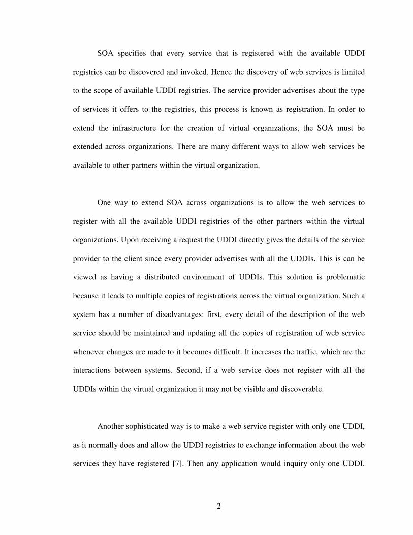
SOA specifies that every service that is registered with the available UDDI
registries can be discovered and invoked. Hence the discovery of web services is limited
to the scope of available UDDI registries. The service provider advertises about the type
of services it offers to the registries, this process is known as registration. In order to
extend the infrastructure for the creation of virtual organizations, the SOA must be
extended across organizations. There are many different ways to allow web services be
available to other partners within the virtual organization.
One way to extend SOA across organizations is to allow the web services to
register with all the available UDDI registries of the other partners within the virtual
organizations. Upon receiving a request the UDDI directly gives the details of the service
provider to the client since every provider advertises with all the UDDIs. This is can be
viewed as having a distributed environment of UDDIs. This solution is problematic
because it leads to multiple copies of registrations across the virtual organization. Such a
system has a number of disadvantages: first, every detail of the description of the web
service should be maintained and updating all the copies of registration of web service
whenever changes are made to it becomes difficult. It increases the traffic, which are the
interactions between systems. Second, if a web service does not register with all the
UDDIs within the virtual organization it may not be visible and discoverable.
Another sophisticated way is to make a web service register with only one UDDI,
as it normally does and allow the UDDI registries to exchange information about the web
services they have registered [7]. Then any application would inquiry only one UDDI.
3
Upon receiving the inquiry, the UDDI may solve it directly if it has the required
information, or it may contact other UDDIs to find the requested service, and reports
back to the client what it found. The difficulty of this solution is that UDDI registries
should discover each other. The local registry has to query all the available UDDIs within
the virtual organization about the service needed. The amount of queries increases
polynomially with the increase of partners in the virtual organization.
In Extended Service-oriented architecture (ESOA), the virtual organization
establishes a UDDI registry, called Main Registry, that collects the registrations of the
partner registries and answers queries about which registry is more likely to contain a
specified type of service [7]. In this model, whenever a local UDDI could not find
information about the type of service requested, it only has to query the Main registry
rather than all the UDDIs within the virtual organization. This reduces the number of
queries placed. But the drawbacks of this model are: first, if for any reason there is a
central point of failure, i.e., if the Main registry goes down then the situation comes back
to the previous model where the local UDDI registry has to contact all the available
UDDIs within the virtual organization. Second, if an application places a request for the
type of service which was requested before by another application within the scope of
same UDDI. The UDDI has to repeat the discovery process again by querying the Main
registry. There are chances that the process will be repeated if many requests are placed
for same kind of web service.
4
The proposed model is developed to resolve the issues of the above mentioned
ESOA structure. The main aspect of this thesis is to develop an architectural model to
support the creation of virtual organizations, and is called a Virtual Service-oriented
Architecture (VSOA). VSOA is based on the observation that UDDI registries are
themselves web services also. Hence it provides a way for the UDDIs to discover each
other within a virtual organization. It extends ESOA by introducing a registry, called the
Cache Registry locally within an organization that acts as a registry to support discovery
of service providers belonging to different organizations and also contain details of the
services offered. Like in ESOA, when a client places a request for a service and if the
local UDDI does not have the required information, it queries the Main registry. And the
results it gets from the Main registry are stored in the Cache registry locally. So whenever
a service request is placed, first the requester queries the cache registry to check if it can
provide the information about the provider of the placed request. Cache registry is
updated each time a new service is requested by the consumer, along with the results it
got from the providing organization.
5
CHAPTER II
LITERATURE REVIEW
2.1. Service-oriented Architecture
Service-oriented Architecture is an approach used to define integration
architectures based on the concept of services. A Service-Oriented Architecture (SOA) is
an architectural style whose goal is to achieve loose coupling among interacting software
agents. Service-oriented architecture defines concepts and general techniques for
designing, encapsulating, and invoking reusable business functions through loosely
bound service interactions [1]. SOA presents an approach for building distributed systems
that deliver application functionality as services to either end-user applications or other
services. It is comprised of elements that can be categorized into functional and quality of
service. In a SOA, services are given the highest importance. Services are defined by the
independent interfaces. All services encapsulate reusable business functions and can be
invoked using communication protocols. The encapsulation of services by interfaces and
their invocation through interoperable protocols are the means by which SOA enables
greater flexibility and reusability.
6
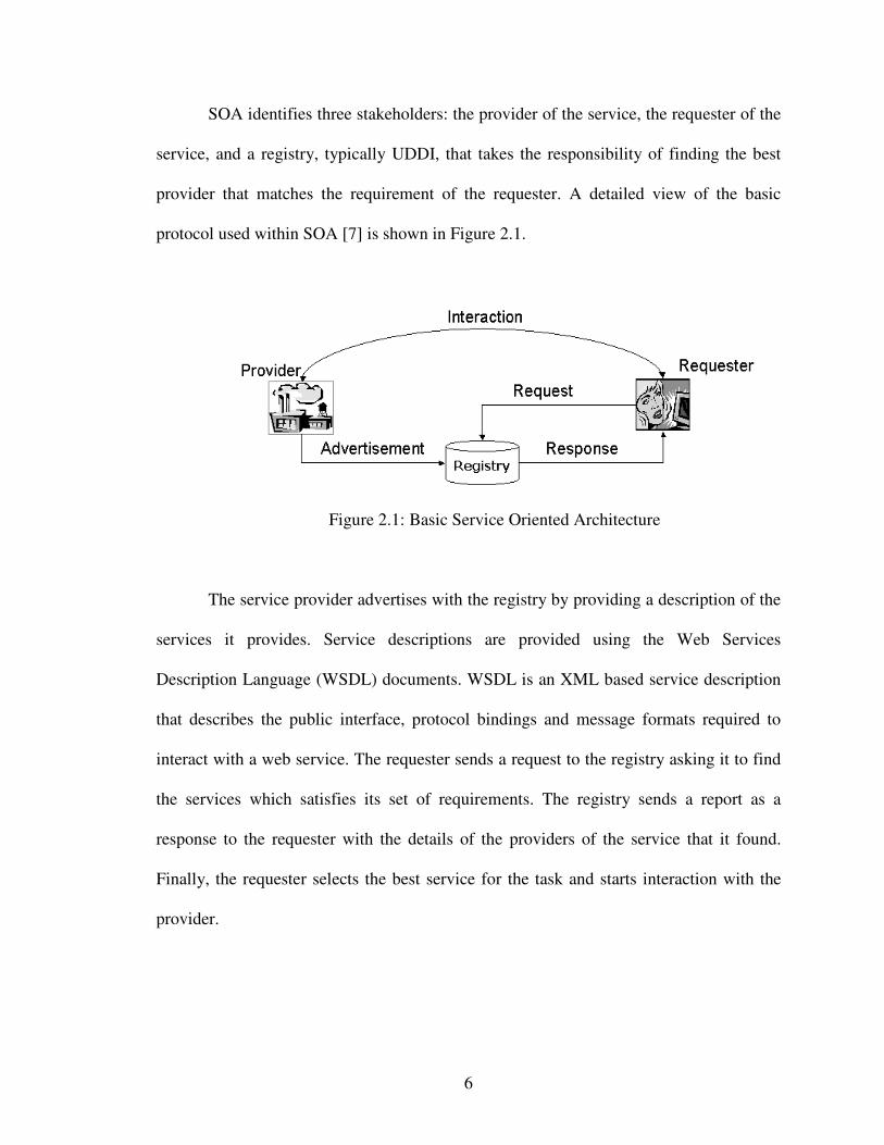
SOA identifies three stakeholders: the provider of the service, the requester of the
service, and a registry, typically UDDI, that takes the responsibility of finding the best
provider that matches the requirement of the requester. A detailed view of the basic
protocol used within SOA [7] is shown in Figure 2.1.
Figure 2.1: Basic Service Oriented Architecture
The service provider advertises with the registry by providing a description of the
services it provides. Service descriptions are provided using the Web Services
Description Language (WSDL) documents. WSDL is an XML based service description
that describes the public interface, protocol bindings and message formats required to
interact with a web service. The requester sends a request to the registry asking it to find
the services which satisfies its set of requirements. The registry sends a report as a
response to the requester with the details of the providers of the service that it found.
Finally, the requester selects the best service for the task and starts interaction with the
provider.
7
A SOA uses a web services as a communication mechanism with XML
documents being routed over an Enterprise Service Bus. Existing host applications
become service providers in a service-oriented architecture. The ESB will carry the
XML-based documents and route them depending on the content. Routing and
orchestration are the fundamental parts of an ESB along with other services like
management, guaranteed delivery and security. Interoperability is the most important
aspect of a SOA. Remote invocation is provided through Simple Object Access Protocol
(SOAP), Web Services Description Language (WSDL) is used to describe the service
interfaces and the services are discovered through the use of Universal Description
Discovery and Integration (UDDI).
2.2. Enterprise Service Bus
The Enterprise Service Bus (ESB) enables an SOA by providing the connectivity
layer between services. The ESB is primarily concerned with the program-to-program
communications necessary to support services-oriented interactions and combines
messaging, transformation, and content-based routing into a single product. The ESB can
be designed according to the business process services of the company implementing it.
Descriptions of the services available from a service provider can be accessed by the
service requestors with the help of registry of services. In order to participate in ESB-
managed interactions the service endpoints need to register with the ESB. The service
providers publish the meta-data about their capabilities and services they offer and the
service requestors publish the meta-data about the kind of information they are looking
8
for. The ESB manages the meta-data through a registry, which supports configuration,
connection, matchmaking and discovery of service endpoints. The meta-data describes
service requestors and providers, mediations and their operations on the information that
flows between requestors and providers, and the discovery, routing and matchmaking that
takes place dynamically.
2.2.1. The role of ESB and other SOA components
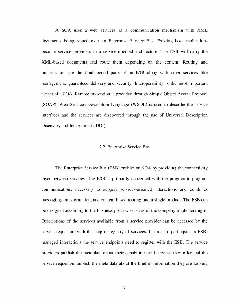
The ESB is not the only infrastructure in SOA, there are other components whose
role is to be positioned relative to the ESB [1]. The figure 2.2 shows the relationship
between all the components.
Figure 2.2: The role of the ESB in a SOA
9
� The Business Service Directory, which provides the details of the services
available to the systems participating in the SOA. The main goal of the business
service directory is to publish the availability of services and encourage their
reuse by the development activity of an enterprise. The business service directory
can be implemented as a design-time service catalogue or an open-standard
Universal Description, Discovery and Integration UDDI directory that enables
dynamic discovery and invocation of business services.
� ESB Namespace Directory, which provides the basic routing information by
means of a routing table.
� The Business Service Choreography, which is used to orchestrate the sequences
of service interactions. The role of choreography is to define and execute business
processes, whose flows are determined by the business logic. Such kind of
behavior is not part of the ESB, but ESB is responsible for functions that involve
sequencing, mediations and other invocations of technical services around the
invocations of business process.
� The ESB Gateway, which is used to provide a controlled point of external access
to the services where the ESB does not provide it locally. Large organizations will
keep the gateway as a separate component, which can also be used to federate
ESBs within an enterprise. The ESB gateway makes the services of one
organization available to others in a controlled and secure manner.
10
2.2.2. Emerging patterns for integrating different ESBs
Within an organization, the need to have different ESBs arises if they have
different governance bodies, funding models, geography, different business strategies.
The use of SOA techniques for integration is called Service Oriented Integration (SOI).
These are three emerging patterns for ESB Topology [4].
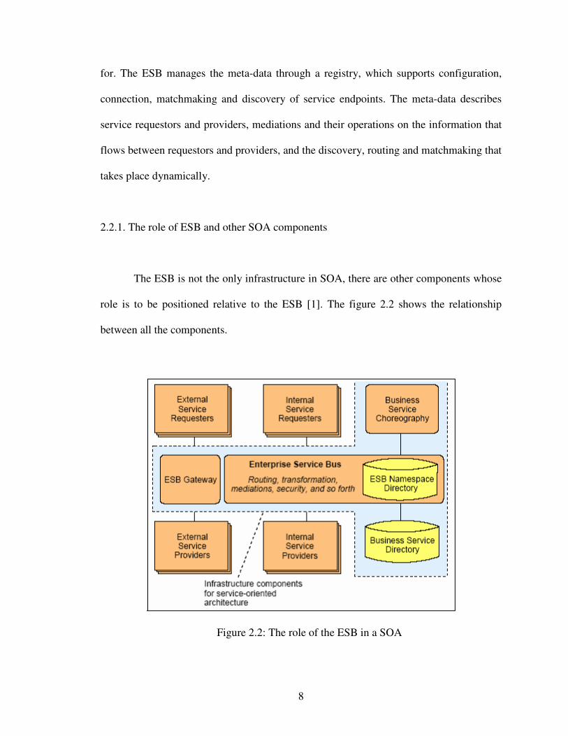
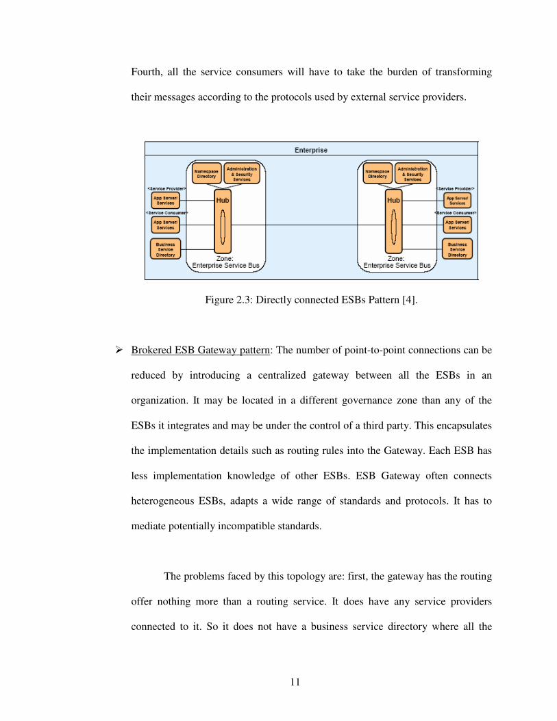
� Directly connected ESBs pattern: This pattern is used to route messages between
two ESBs. Service consumer of one ESB connects with the service provider of
other ESB and the link is created between them. As a point-to-point topology, the
endpoints contain the implementation knowledge of each other. For example, the
ESB hosting service consumer must know which ESB hosts the service provider,
what protocol to use to get the service done, and message format so it can route
the request. This result in service routing rules distributed across multiple ESBs
and in multiple ESB components. The consumer ESB should transform their
messages so that the service provider understands the message and performs the
operation.
The problems faced in this model are: first, only two ESB can
communicate at a time. Second, service provider location must be known to the
service consumer before invoking it. Third, the number of links grows
exponentially as the number of components being linked together grows.
Maintenance will increase as the number of links between ESBs increases.
11
Fourth, all the service consumers will have to take the burden of transforming
their messages according to the protocols used by external service providers.
Figure 2.3: Directly connected ESBs Pattern [4].
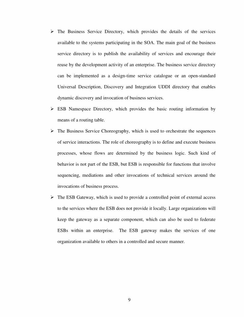
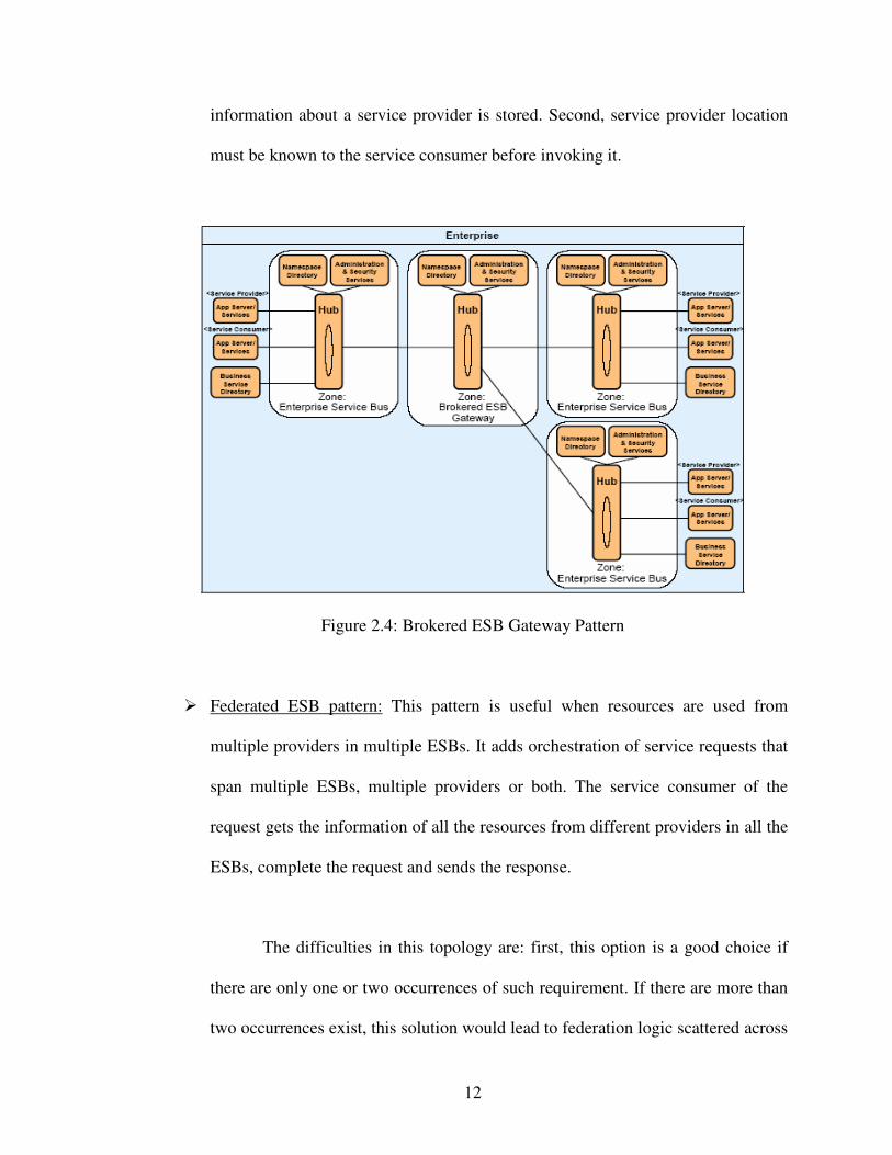
� Brokered ESB Gateway pattern: The number of point-to-point connections can be
reduced by introducing a centralized gateway between all the ESBs in an
organization. It may be located in a different governance zone than any of the
ESBs it integrates and may be under the control of a third party. This encapsulates
the implementation details such as routing rules into the Gateway. Each ESB has
less implementation knowledge of other ESBs. ESB Gateway often connects
heterogeneous ESBs, adapts a wide range of standards and protocols. It has to
mediate potentially incompatible standards.
The problems faced by this topology are: first, the gateway has the routing
offer nothing more than a routing service. It does have any service providers
connected to it. So it does not have a business service directory where all the
12
information about a service provider is stored. Second, service provider location
must be known to the service consumer before invoking it.
Figure 2.4: Brokered ESB Gateway Pattern
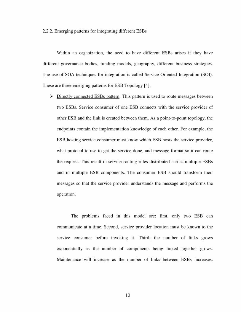
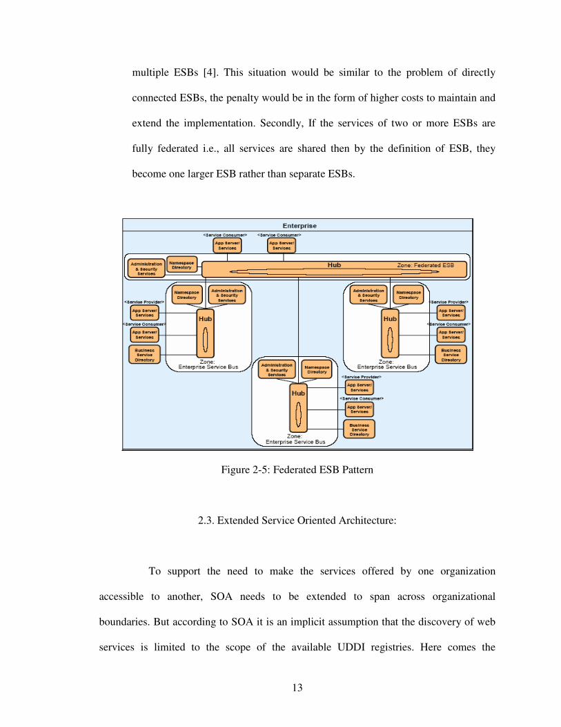
� Federated ESB pattern: This pattern is useful when resources are used from
multiple providers in multiple ESBs. It adds orchestration of service requests that
span multiple ESBs, multiple providers or both. The service consumer of the
request gets the information of all the resources from different providers in all the
ESBs, complete the request and sends the response.
The difficulties in this topology are: first, this option is a good choice if
there are only one or two occurrences of such requirement. If there are more than
two occurrences exist, this solution would lead to federation logic scattered across
13
multiple ESBs [4]. This situation would be similar to the problem of directly
connected ESBs, the penalty would be in the form of higher costs to maintain and
extend the implementation. Secondly, If the services of two or more ESBs are
fully federated i.e., all services are shared then by the definition of ESB, they
become one larger ESB rather than separate ESBs.
Figure 2-5: Federated ESB Pattern
2.3. Extended Service Oriented Architecture:
To support the need to make the services offered by one organization
accessible to another, SOA needs to be extended to span across organizational
boundaries. But according to SOA it is an implicit assumption that the discovery of web
services is limited to the scope of the available UDDI registries. Here comes the
14
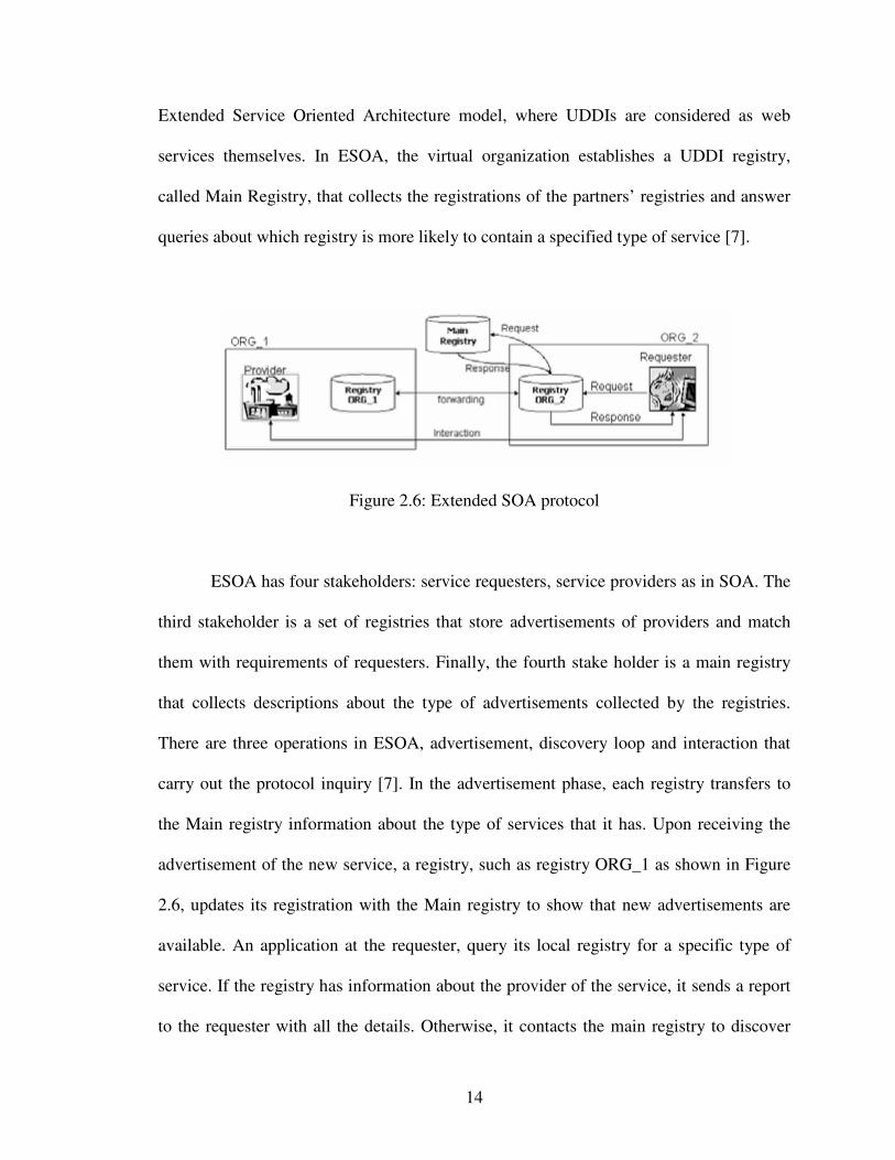
Extended Service Oriented Architecture model, where UDDIs are considered as web
services themselves. In ESOA, the virtual organization establishes a UDDI registry,
called Main Registry, that collects the registrations of the partners’ registries and answer
queries about which registry is more likely to contain a specified type of service [7].
Figure 2.6: Extended SOA protocol
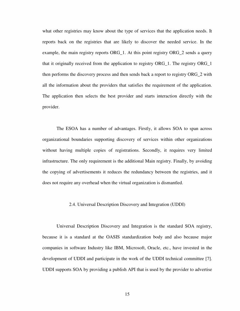
ESOA has four stakeholders: service requesters, service providers as in SOA. The
third stakeholder is a set of registries that store advertisements of providers and match
them with requirements of requesters. Finally, the fourth stake holder is a main registry
that collects descriptions about the type of advertisements collected by the registries.
There are three operations in ESOA, advertisement, discovery loop and interaction that
carry out the protocol inquiry [7]. In the advertisement phase, each registry transfers to
the Main registry information about the type of services that it has. Upon receiving the
advertisement of the new service, a registry, such as registry ORG_1 as shown in Figure
2.6, updates its registration with the Main registry to show that new advertisements are
available. An application at the requester, query its local registry for a specific type of
service. If the registry has information about the provider of the service, it sends a report
to the requester with all the details. Otherwise, it contacts the main registry to discover
15
what other registries may know about the type of services that the application needs. It
reports back on the registries that are likely to discover the needed service. In the
example, the main registry reports ORG_1. At this point registry ORG_2 sends a query
that it originally received from the application to registry ORG_1. The registry ORG_1
then performs the discovery process and then sends back a report to registry ORG_2 with
all the information about the providers that satisfies the requirement of the application.
The application then selects the best provider and starts interaction directly with the
provider.
The ESOA has a number of advantages. Firstly, it allows SOA to span across
organizational boundaries supporting discovery of services within other organizations
without having multiple copies of registrations. Secondly, it requires very limited
infrastructure. The only requirement is the additional Main registry. Finally, by avoiding
the copying of advertisements it reduces the redundancy between the registries, and it
does not require any overhead when the virtual organization is dismantled.
2.4. Universal Description Discovery and Integration (UDDI)
Universal Description Discovery and Integration is the standard SOA registry,
because it is a standard at the OASIS standardization body and also because major
companies in software Industry like IBM, Microsoft, Oracle, etc., have invested in the
development of UDDI and participate in the work of the UDDI technical committee [7].
UDDI supports SOA by providing a publish API that is used by the provider to advertise
16
the web services, and an inquiry API that allows requesters to search for web services and
to retrieve information about the registered services. Web services are described in UDDI
by a set of data structures that are used to specify the business that deployed the service,
the service itself and all the bindings of the service.
The success of ESOA hinges on the ability to provide an effective discovery
mechanism. The problem of service discovery arises as the provider and requester of the
service may have different perspectives on the same service advertised. For example, a
provider of the service may report many different types of information about a service,
whereas the requester might need only one type of information. Thus a matching process
needs to recognize the similarity between the meaning of the request and the meaning of
the advertisement. The web services technologies, SOAP, WSDL, and UDDI rely on
XML for interoperability.
17
CHAPTER III
PROPOSED APPROACH
This thesis proposes an architectural model to provide IT infrastructure for virtual
organizations, so that information can flow easily within virtual organizations. The
creation of virtual organizations becomes important as the services offered by one
organization should become accessible to other organizations. This proposed model, that
we call Virtual Service-Oriented Architecture or VSOA in short, is based on the
observation that UDDI registries are themselves web services and is also a way to extend
ESOA to deal with virtual organizations. In ESOA, if a situation arises where the same
kind of request is placed from different customers within an organization at different
times, the entire discovery and interaction phases needs to be repeated. In other words,
the central Main registry is first contacted. The Main registry returns the registries that
are likely to discover the set of providers which offer the requested service. The local
UDDI registry which placed the original request contacts all the registries of the
providers (local registries of all partner organizations). They provide more details about
the providers such as the type of services they offer, the protocols they use, and other
such details. The application then selects one of these providers based on some criteria.
Furthermore, since there is no local caching, a customer who has previously requested a
service will have to go through the whole process again if another request is made for the
same service again.
18
Repeating the whole process is time consuming and increases the number of
requests to query the Main registry as well as the requests to local registries when there
are repeated requests. The proposed architecture makes the Information discovery
process across organizations more flexible and efficient.
The drawbacks of the ESOA which are dealt by VSOA are, firstly, VSOA deals
with the central point of failure problem. If for any reason the central point in ESOA, i.e.,
the Main Registry fails, then the situation reverts back to the basic SOA model where the
service providers not only advertises with the local UDDI but also with all the UDDIs
available in the network. VSOA deals with this problem by introducing another local
registry called the Cache Registry, where all the results received by the requestor
application about the services it needs are stored and are available for retrieval whenever
the same kind of request is placed next time without actually going through the entire
procedure again. This to some extent, if not fully, solves the center point of failure
problem. Even if the Main Registry goes down, the proposed VSOA model helps to
process the requests that require the same type of services that were handled before.
Some simulations will be run at later stages of the thesis to get the measurements of what
percentage of services can be processed even when the Main registry fails. We assume
that the central point will be restored after sometime.
Secondly, suppose that the same service is requested more than once by different
requesters within the same organization at different times. According to ESOA, the
discovery phase has to be repeated each time the request is placed. This consumes much
19
time and increases the number of requests made to query the main registry. In VSOA, all
the information about a service requested is stored in the cache registry. The cache
registry consists of information such as the name of the web service, the business that
deployed the service and exact location of the service provider. Whenever the same kind
of request is repeated, it can be accessed locally easily and the information about the
provider of service can be directly obtained. This reduces the number of procedures it has
to go through and can contact the provider directly using the provider address in cache.
Thirdly, our proposed approach reduced the communication bottleneck introduced
by a central point of communications. Network traffic is much more distributed.
3.1. VSOA: Virtual Service Oriented Architecture
To support the needs of virtual organizations and to make them perform
efficiently, ESOA should be extended, without requiring an organization’s UDDI
registries to perform the same set of operations again and again. One way to approach
this problem is to think of the UDDI registry as a web service itself. Another local
registry is used that acts as a registry to support discovery of service providers belonging
to different organizations and contain the information about the services offered.
VSOA has five stakeholders: service requestors, service providers, the third
stakeholder is a set of registries that store the advertisements of local providers to match
them with the requirements of service requesters which may or may not be local, the
20
fourth stakeholder is the Main Registry, that holds the descriptions of the type of services
or advertisements collected by each of the organizations registries as in ESOA. Finally,
the fifth stakeholder is the Cache Registry, which collects the results obtained by the
service requester in its new service request. This registry can be viewed for information
retrieval when the same kind of request is placed the next time.
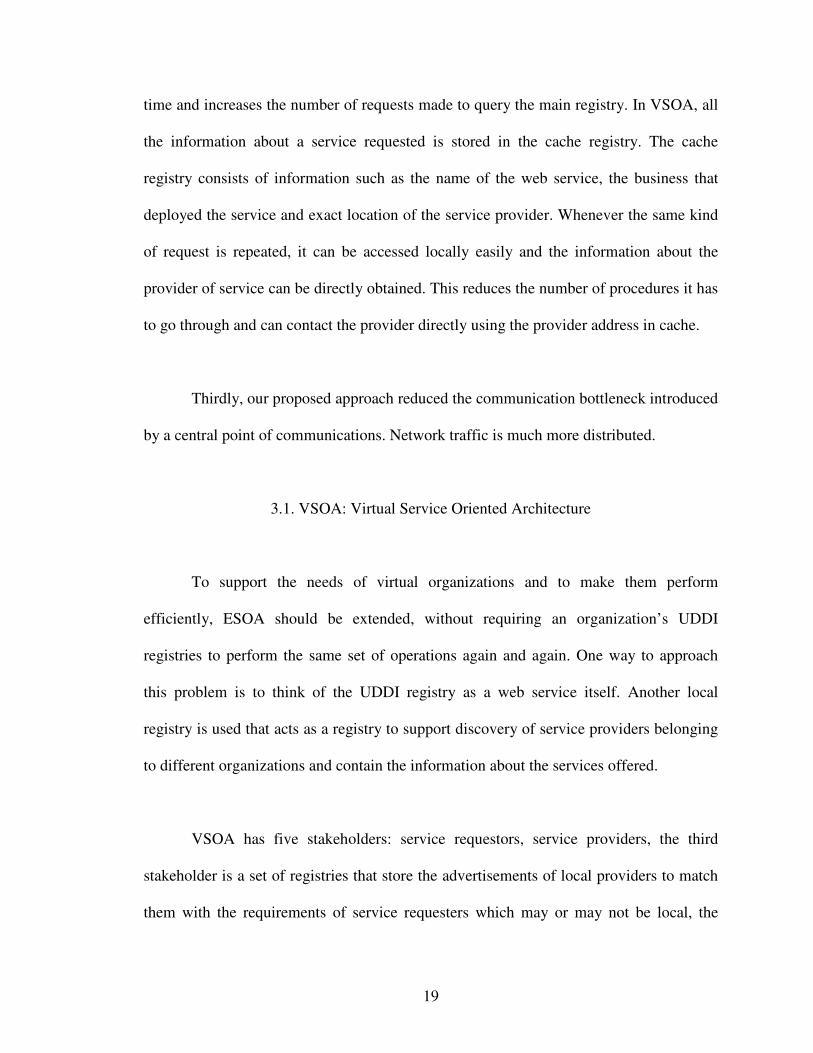
Figure 3.1: Advertising in the VSOA architecture
The four operations that characterize the VSOA protocol are advertisement,
discovery, collection and interaction, which are applied to organizational registries and
the services. In the advertisement phase as shown in Figure 3.1 whenever a new service is
added or any changes are made to the existing services, the provider updates the local
registry which in turn updates the main registry with the information and details of the
services. The discovery process happens in three stages by using the local UDDI
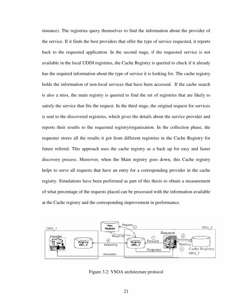
registries, Main registry and the Cache; the attributes of these are shown in Table 3.1.
First, the application which needs a particular type of service queries the local
organization’s UDDI registry for the required information. This is because the local
UDDI may contain services that have not been accessed before (new services for
21
instance). The registries query themselves to find the information about the provider of
the service. If it finds the best providers that offer the type of service requested, it reports
back to the requested application. In the second stage, if the requested service is not
available in the local UDDI registries, the Cache Registry is queried to check if it already
has the required information about the type of service it is looking for. The cache registry
holds the information of non-local services that have been accessed. If the cache search
is also a miss, the main registry is queried to find the set of registries that are likely to
satisfy the service that fits the request. In the third stage, the original request for services
is sent to the discovered registries, which gives the details about the service provider and
reports their results to the requested registry/organization. In the collection phase, the
requester stores all the results it got from different registries in the Cache Registry for
future referral. This approach uses the cache registry as a back up for easy and faster
discovery process. Moreover, when the Main registry goes down, this Cache registry
helps to serve all requests that have an entry for a corresponding provider in the cache
registry. Simulations have been performed as part of this thesis to obtain a measurement
of what percentage of the requests placed can be processed with the information available
at the Cache registry and the corresponding improvement in performance.
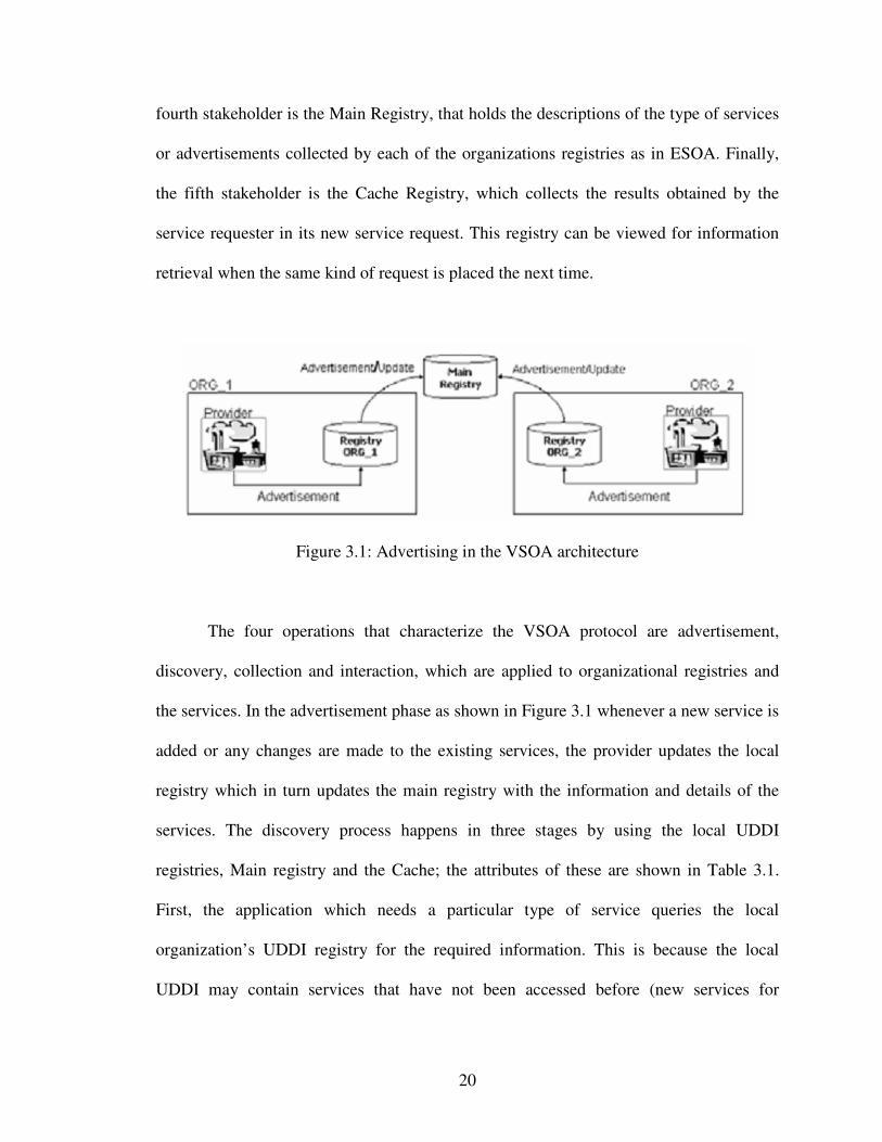
Figure 3.2: VSOA architecture protocol
22
Attributes Local UDDIregistries
MainRegistry
CacheRegistry
Name/Type of Service Y Y YDeployed organization/UDDI N Y Y
Bindings of Services like protocols,message formats, etc.,
Y Y Y
Location of Service (interface or URL) Y N YTable 3.1. Attributes of different registries in VSOA
In the request phase, the application at first queries their local registry for the
service type. If the registry knows about the services that satisfy the requirements of the
application, it will report on those services. If service provider information is not found,
the Cache registry is checked to see if it can get the required information about the type
of services it is needs. The time to go through the discover process all over again will be
saved if the required information is available in the cache registry. Otherwise, as shown
in Figure 3.2 the local registry queries the Main Registry to discover what other registries
know about the type of services that the application needs. The main registry performs
the discovery process and sends back all the information about the registries that can
process the request placed. In the example in the Figure 3.2, the main registry may report
ORG_1. At this point Registry ORG_2 sends the original query that it received from the
application directly to Registry ORG_1 which performs the discovery process, locates the
best set of services and reports them back to the Registry ORG_2. In turn, registry
ORG_2 reports these services, and all the other services that it discovered to the
application. The application then stores these reports in the cache and contacts the
provider directly.
23
The use of VSOA has a number of advantages. It allows the SOA to span across
organizational boundaries and also saves time in the discovery process by using a Cache
Registry to store the information about the type of services it already processed. The
second advantage is it requires limited additional infrastructure when compared to ESOA.
The only requirement is the additional Cache Registry. The third advantage is that it
partially solves the central point failure problem. When the Main registry fails, the
application can still be processed if a request is placed for the same type of services that
have already been processed. It also reduces the traffic bottleneck at the main registry.
3.2. Response Times
We provide a simple comparison of the ESOA and VSOA systems in terms of
response times.
Assume there are W web services and these are distributed across E ESBs
Assume there are C clients
Therefore on average each ESB will have W/E web services and C/E clients
Let pik denote the probability of a client requestor i at a ESB site accessing a web service
k at a remote ESB site. The cost to access this is tr
Let pij denote the probability of a client requestor i at a ESB site accessing a web service
at a local ESB site i. The time to access this is tl
The total cost for all accesses will therefore be
24
+
∑ ∑∑∑=
−
== =
EC
ir
EEW
kik
EC
il
EW
jij tpEtpE
1
)1(
11 1
where tr > tl
This is the cost for a ESOA access. We have assumed that tr and tl are the same for all
ESB sites.
The cost for a VSOA access will be
+
∑ ∑∑∑=
−
== =
EC
ir
EEW
kik
EC
il
EW
jij cpEtpE
1
)1(
11 1
Here we have defined the remote cost access in terms of a cost cr
The cost for a VSOA access is reduced since some of the remote accesses become local
accesses. Let pikL-H be the local cache hit probability and pik
R-U be the remote UDDI hit
probability for all web services pik that denote the probability of a client requestor i at a
ESB site accessing a web service k at a remote ESB site.. As a result of caching the
requested web service is available either locally or remotely.
)()( 'UR
ikrHL
iklr ptptc −− ×+×=
where tl’ is the time for local cache access and is very close to tl.
It is evident that pikR-U = 1 - pik
L-H
The objective is to minimize cr. This requires identifying appropriate measures to
minimize pikR-U and maximize pik
L-H. This simple model needs to be extended to obtain
more detailed expressions for pikR-U atd pik
L-H. This clearly is a function of the placement
and replacement strategies that will be employed. The next question that arises is which
web service entries to keep in the local cache. The probability of a web service being
buffered locally depends on whether the service is considered important enough to be put
25
in the local cache. If this web service is likely to be regularly accessed, it is worth
buffering it locally. On the other hand, if it is going to be accessed very rarely, it may not
be worth maintaining it locally and instead to use the space for other more important web
services. Therefore the characteristics of the other services that have been requested must
also be considered if they should instead be placed in the local cache. A number of
approaches such as least recently used or most frequently used or a combination of the
different schemes may be used.
26
CHAPTER IV
SIMULATION MODEL
4.1. Simulation Implementation Details
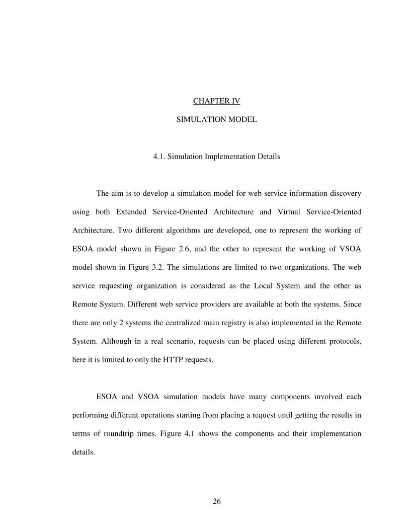
The aim is to develop a simulation model for web service information discovery
using both Extended Service-Oriented Architecture and Virtual Service-Oriented
Architecture. Two different algorithms are developed, one to represent the working of
ESOA model shown in Figure 2.6, and the other to represent the working of VSOA
model shown in Figure 3.2. The simulations are limited to two organizations. The web
service requesting organization is considered as the Local System and the other as
Remote System. Different web service providers are available at both the systems. Since
there are only 2 systems the centralized main registry is also implemented in the Remote
System. Although in a real scenario, requests can be placed using different protocols,
here it is limited to only the HTTP requests.
ESOA and VSOA simulation models have many components involved each
performing different operations starting from placing a request until getting the results in
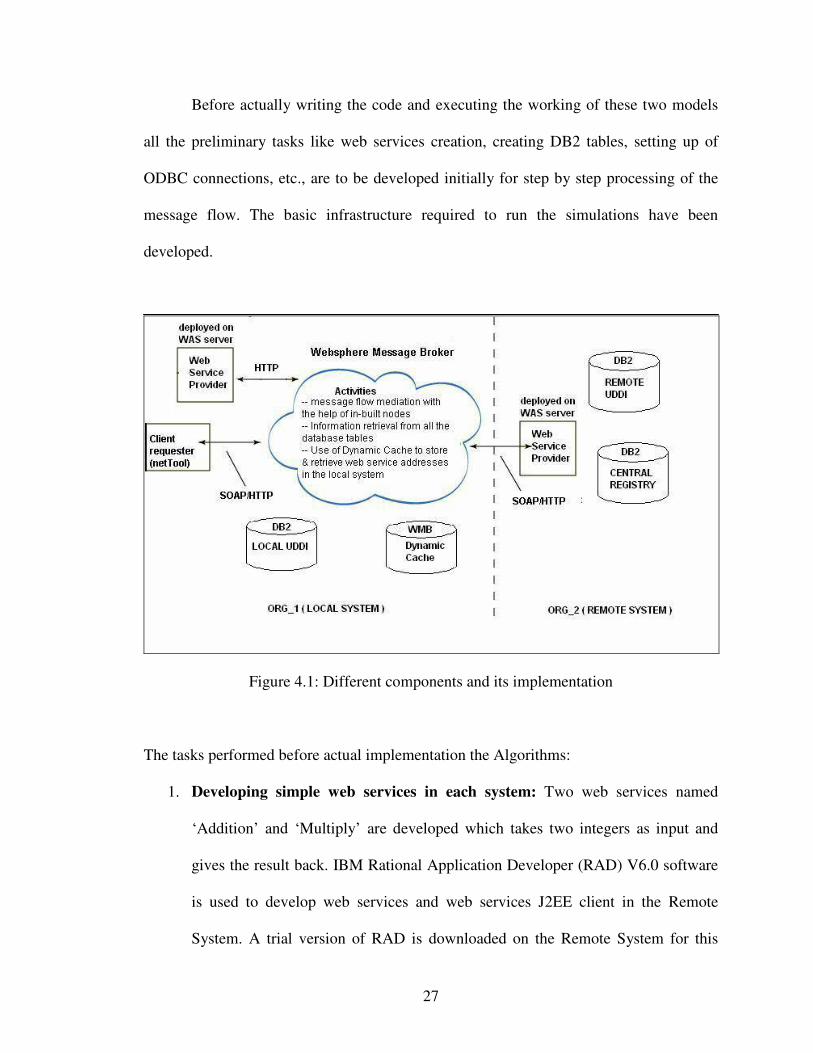
terms of roundtrip times. Figure 4.1 shows the components and their implementation
details.
27
Before actually writing the code and executing the working of these two models
all the preliminary tasks like web services creation, creating DB2 tables, setting up of
ODBC connections, etc., are to be developed initially for step by step processing of the
message flow. The basic infrastructure required to run the simulations have been
developed.
Figure 4.1: Different components and its implementation
The tasks performed before actual implementation the Algorithms:
1. Developing simple web services in each system: Two web services named
‘Addition’ and ‘Multiply’ are developed which takes two integers as input and
gives the result back. IBM Rational Application Developer (RAD) V6.0 software
is used to develop web services and web services J2EE client in the Remote
System. A trial version of RAD is downloaded on the Remote System for this
28
purpose [11]. RAD is an eclipse based application developer used to design,
develop, analyze, test and deploy web, SOA, java, and J2EE applications [10].
The web service needs a server to deploy the code generated. Hence Websphere
Application Server (WAS) V6.0 trial version is downloaded [14]. Here, WAS was
just used as a server to deploy the web services created. In the Local System, web
service is developed using the java tool in Websphere Message Broker and
deployed on WAS. The request for web service is placed using the netTool which
requires the Simple Object Access Protocol (SOAP) format to post the request.
The input message consists of mainly 2 parameters: the service type which is the
name of the service required, and the input values. The web services available are
to be published in their respective local UDDI registries in order to get recognized
and invoked.
2. Setting up UDDI registries and the communication between two DB2
databases: In general, web services are described in UDDI by a set of data
structures that are used to specify the business that deployed the service, the
service itself and all the bindings of the service. It provides 2 APIs for publish and
inquiry operations about web services. In this simulation, UDDI registries are
assumed to be the database tables. A trial version of IBM DB2 is downloaded to
setup the databases [13]. The UDDIs in the Local and Remote Systems are named
as LOCAL_UDDI and REMOTE_UDDI respectively. Both these tables have 3
attributes to describe a web service, the index, service name/type, and the address
of the web service provider. After the creation of web services its details are
29
entered into the local database tables. When a request is placed the database is
queried using simple select statements based on service type.
Another table named CENTRAL_REGISTRY is created to represent the
Main Registry, which collects descriptions about the type of advertisements
collected by all the local registries in the virtual organization. The attributes of
this table are: the index, service type, the UDDI registry where the service is
available, and the datasource name which is the name of the database. The
applications need to access the databases of both Local and Remote Systems to
retrieve the web service address during execution. Hence, ODBC connections are
setup for the databases in both the systems.
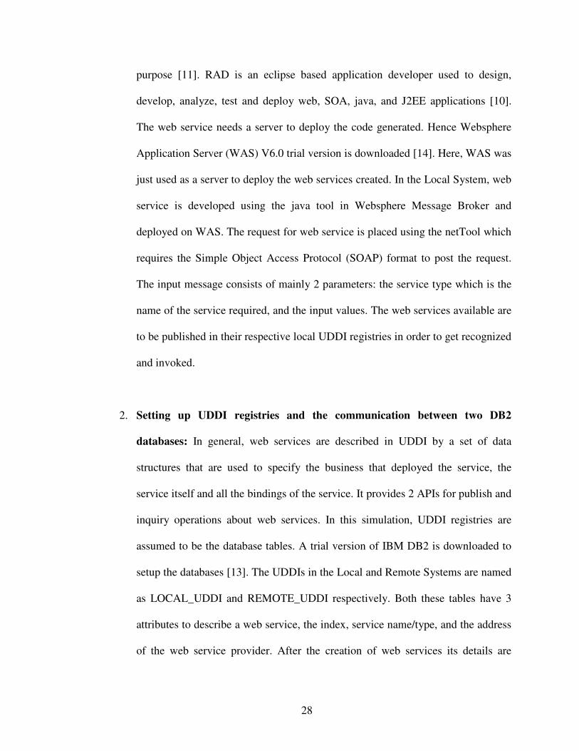
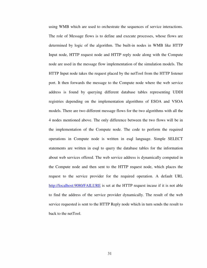
3. NetTool Client download: NetTool is a developer tool for monitoring and
manipulating application-level network messages, particularly useful for
debugging web applications and web services. It is a free access software
available online. There are two components to NetTool: the HTTP Client, and the
TCP Tunnel. The HTTP client is used to place a request for the web service. The
request is placed as a SOAP message to the HTTP Input node of the message
broker. The HTTP Input node listens at, http://localhost:7080/Algorithm2 for the
ESOA algorithm and at http://localhost:7080/Algorithm1 for the VSOA
algorithm. The HTTP listener at port 7080 listens to the incoming request and
forwards it to the message flow of the message broker for further processing and
sends back the result to the netTool. The netTool gets the value of the result for
30
the requested operation (Addition/Multiply) and also the roundtrip time taken to
process the placed request in ms.
Figure 4.2: netTool Interface
4. Websphere Message Broker (WMB) and message flows: The trial version of
Websphere Message Broker (WMB) V6.0 is downloaded in one of the systems
from where the request is placed. WMB is an Eclipse-based tool that delivers an
advanced Enterprise Service Bus providing connectivity and data transformation
for applications and services in a SOA. It integrates with multiple sources of data
such as databases, applications and files to perform data manipulation. It
simplifies the integration of existing applications with web services by
transforming and routing SOAP messages. The message flows are developed
31
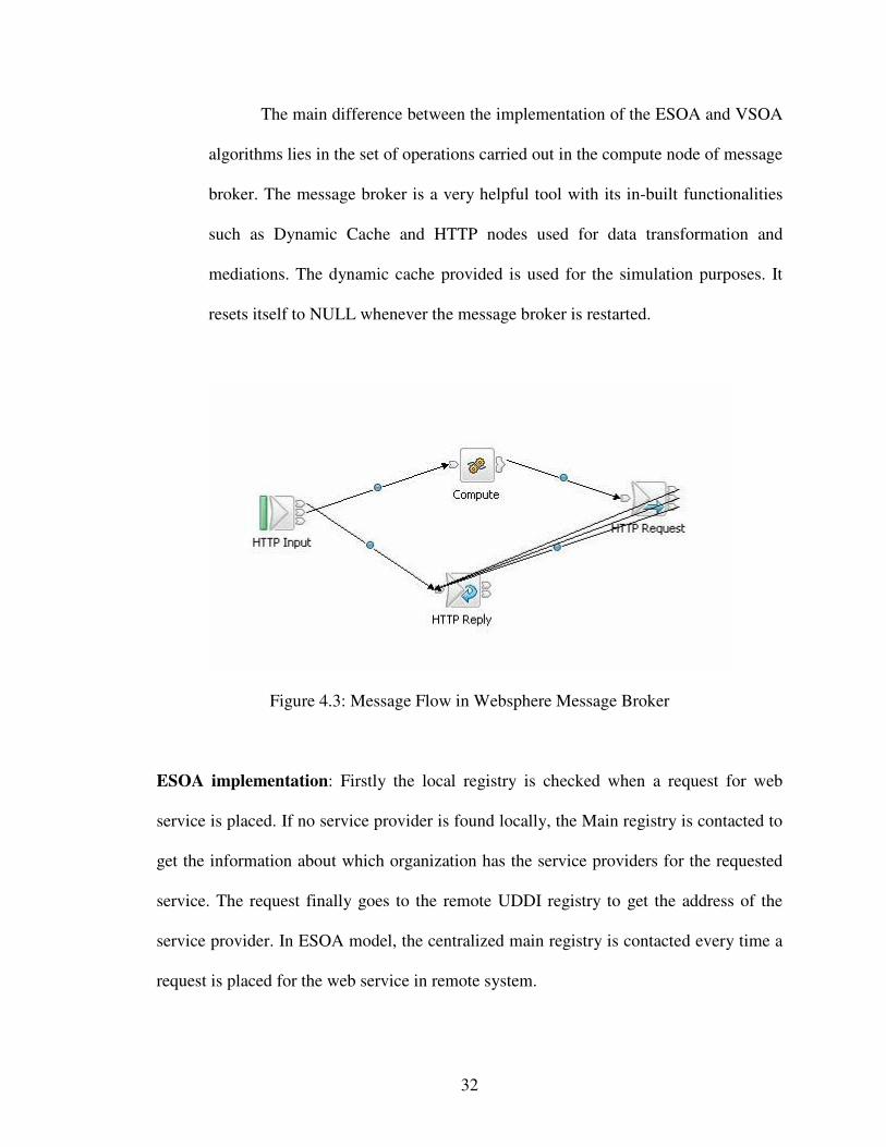
using WMB which are used to orchestrate the sequences of service interactions.
The role of Message flows is to define and execute processes, whose flows are
determined by logic of the algorithm. The built-in nodes in WMB like HTTP
Input node, HTTP request node and HTTP reply node along with the Compute
node are used in the message flow implementation of the simulation models. The
HTTP Input node takes the request placed by the netTool from the HTTP listener
port. It then forwards the message to the Compute node where the web service
address is found by querying different database tables representing UDDI
registries depending on the implementation algorithms of ESOA and VSOA
models. There are two different message flows for the two algorithms with all the
4 nodes mentioned above. The only difference between the two flows will be in
the implementation of the Compute node. The code to perform the required
operations in Compute node is written in esql language. Simple SELECT
statements are written in esql to query the database tables for the information
about web services offered. The web service address is dynamically computed in
the Compute node and then sent to the HTTP request node, which places the
request to the service provider for the required operation. A default URL
http://localhost:9080/FAILURE is set at the HTTP request incase if it is not able
to find the address of the service provider dynamically. The result of the web
service requested is sent to the HTTP Reply node which in turn sends the result to
back to the netTool.
32
The main difference between the implementation of the ESOA and VSOA
algorithms lies in the set of operations carried out in the compute node of message
broker. The message broker is a very helpful tool with its in-built functionalities
such as Dynamic Cache and HTTP nodes used for data transformation and
mediations. The dynamic cache provided is used for the simulation purposes. It
resets itself to NULL whenever the message broker is restarted.
Figure 4.3: Message Flow in Websphere Message Broker
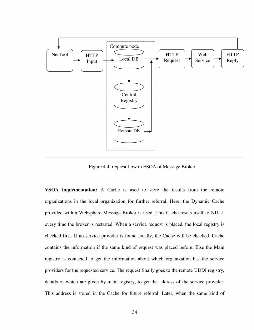
ESOA implementation: Firstly the local registry is checked when a request for web
service is placed. If no service provider is found locally, the Main registry is contacted to
get the information about which organization has the service providers for the requested
service. The request finally goes to the remote UDDI registry to get the address of the
service provider. In ESOA model, the centralized main registry is contacted every time a
request is placed for the web service in remote system.
33
Algorithm:
// Request is placed to the HTTP Input node from netTool.
Given Inputs: service_type & two numbers to http://localhost:7080/Algorithm2
// Message is forwarded to the Compute node where the
// Checks the local database for web service address
{
service_address = SELECT service_address from (LOCAL_UDDI) for given
service_type;
else
// check the central registry for the remote database address where the service
//provider can be found
UDDI_details = SELECT datasource, UDDI from (CENTRAL_REGISTRY) for
given service_type;
// Then contact the remote UDDI for the web service address
service_address = SELECT service_address from UDDI_details registry for given
service_type;
}
-- The service address is sent to the HTTP Request node dynamically which sends the
original request to the web service provider at the service_address
-- The value of the result is sent to the HTTP Reply node which in turn displays it in the
netTool
-- The total roundtrip time starting from placing a request to the display of result is
measured by netTool in millisecond (ms).
34
Figure 4.4: request flow in ESOA of Message Broker
VSOA implementation: A Cache is used to store the results from the remote
organizations in the local organization for further referral. Here, the Dynamic Cache
provided within Websphere Message Broker is used. This Cache resets itself to NULL
every time the broker is restarted. When a service request is placed, the local registry is
checked first. If no service provider is found locally, the Cache will be checked. Cache
contains the information if the same kind of request was placed before. Else the Main
registry is contacted to get the information about which organization has the service
providers for the requested service. The request finally goes to the remote UDDI registry,
details of which are given by main registry, to get the address of the service provider.
This address is stored in the Cache for future referral. Later, when the same kind of
Compute node
NetTool HTTPInput Local DB
CentralRegistry
Remote DB
HTTPRequest
WebService
HTTPReply
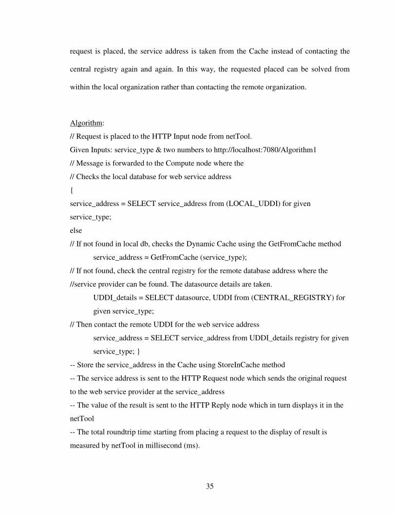
35
request is placed, the service address is taken from the Cache instead of contacting the
central registry again and again. In this way, the requested placed can be solved from
within the local organization rather than contacting the remote organization.
Algorithm:
// Request is placed to the HTTP Input node from netTool.
Given Inputs: service_type & two numbers to http://localhost:7080/Algorithm1
// Message is forwarded to the Compute node where the
// Checks the local database for web service address
{
service_address = SELECT service_address from (LOCAL_UDDI) for given
service_type;
else
// If not found in local db, checks the Dynamic Cache using the GetFromCache method
service_address = GetFromCache (service_type);
// If not found, check the central registry for the remote database address where the
//service provider can be found. The datasource details are taken.
UDDI_details = SELECT datasource, UDDI from (CENTRAL_REGISTRY) for
given service_type;
// Then contact the remote UDDI for the web service address
service_address = SELECT service_address from UDDI_details registry for given
service_type; }
-- Store the service_address in the Cache using StoreInCache method
-- The service address is sent to the HTTP Request node which sends the original request
to the web service provider at the service_address
-- The value of the result is sent to the HTTP Reply node which in turn displays it in the
netTool
-- The total roundtrip time starting from placing a request to the display of result is
measured by netTool in millisecond (ms).
36
Figure 4.5: request flow in VSOA of Message Broker
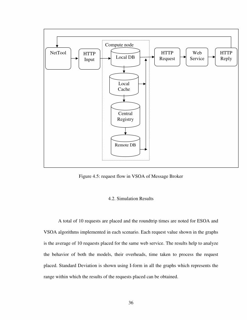
4.2. Simulation Results
A total of 10 requests are placed and the roundtrip times are noted for ESOA and
VSOA algorithms implemented in each scenario. Each request value shown in the graphs
is the average of 10 requests placed for the same web service. The results help to analyze
the behavior of both the models, their overheads, time taken to process the request
placed. Standard Deviation is shown using I-form in all the graphs which represents the
range within which the results of the requests placed can be obtained.
Compute node
NetTool HTTPInput Local DB
CentralRegistry
Remote DB
HTTPRequest
WebService
HTTPReply
LocalCache
37
Assumptions taken while running the algorithms are:
• Even though both the systems used are in the same network, they are assumed to
be in different environments while execution to depict the real-time scenario.
These two systems are assumed as two organizations in the virtual organization
each having its own local UDDI registries and Service Providers.
• The requests made are limited to only SOAP/HTTP protocol.
• The Websphere Message Broker is not restarted while running the algorithms, so
that the Cache is also not reset to NULL.
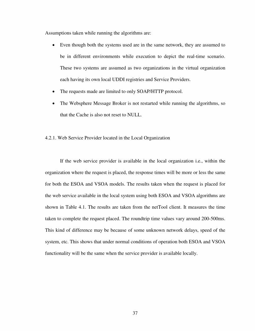
4.2.1. Web Service Provider located in the Local Organization
If the web service provider is available in the local organization i.e., within the
organization where the request is placed, the response times will be more or less the same
for both the ESOA and VSOA models. The results taken when the request is placed for
the web service available in the local system using both ESOA and VSOA algorithms are
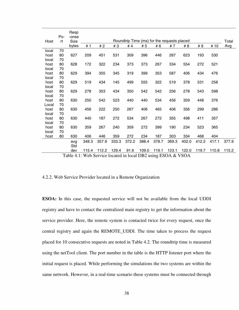
shown in Table 4.1. The results are taken from the netTool client. It measures the time
taken to complete the request placed. The roundtrip time values vary around 200-500ms.
This kind of difference may be because of some unknown network delays, speed of the
system, etc. This shows that under normal conditions of operation both ESOA and VSOA
functionality will be the same when the service provider is available locally.
38
Roundtrip Time (ms) for the requests placedHostPo-rt
Resp-onseSizebytes # 1 # 2 # 3 # 4 # 5 # 6 # 7 # 8 # 9 # 10
TotalAvg
localhost
7080 627 209 451 531 309 396 446 287 623 193 530
localhost
7080 628 172 322 234 373 373 267 334 554 272 521
localhost
7080 629 394 355 345 319 399 353 587 406 434 476
localhost
7080 629 519 434 145 499 555 322 519 378 531 258
localhost
7080 629 278 353 434 350 542 542 256 278 543 598
localhost
7080 630 250 542 523 440 440 534 456 359 448 376
Localhost
7080 630 456 222 250 267 406 465 406 356 299 286
localhost
7080 630 440 187 272 534 267 272 355 498 411 357
localhost
7080 630 359 267 240 359 272 399 190 234 523 365
localhost
7080 630 406 446 359 272 234 187 303 334 468 404
avg 348.3 357.9 333.3 372.2 388.4 378.7 369.3 402.0 412.2 417.1 377.9Stddev 115.4 112.2 129.4 91.6 109.0 119.1 123.1 122.0 119.7 110.8 115.2
Table 4.1: Web Service located in local DB2 using ESOA & VSOA
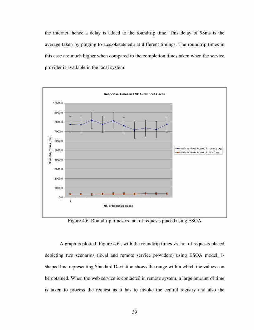
4.2.2. Web Service Provider located in a Remote Organization
ESOA: In this case, the requested service will not be available from the local UDDI
registry and have to contact the centralized main registry to get the information about the
service provider. Here, the remote system is contacted twice for every request, once the
central registry and again the REMOTE_UDDI. The time taken to process the request
placed for 10 consecutive requests are noted in Table 4.2. The roundtrip time is measured
using the netTool client. The port number in the table is the HTTP listener port where the
initial request is placed. While performing the simulations the two systems are within the
same network. However, in a real-time scenario these systems must be connected through
39
the internet, hence a delay is added to the roundtrip time. This delay of 98ms is the
average taken by pinging to a.cs.okstate.edu at different timings. The roundtrip times in
this case are much higher when compared to the completion times taken when the service
provider is available in the local system.
Response Times in ESOA - without Cache
0.0
1000.0
2000.0
3000.0
4000.0
5000.0
6000.0
7000.0
8000.0
9000.0
10000.0
1
No. of Requests placed
Ro
un
dtr
ipT
imes
(ms)
web services located in remote org
web services located in local org
Figure 4.6: Roundtrip times vs. no. of requests placed using ESOA
A graph is plotted, Figure 4.6., with the roundtrip times vs. no. of requests placed
depicting two scenarios (local and remote service providers) using ESOA model. I-
shaped line representing Standard Deviation shows the range within which the values can
be obtained. When the web service is contacted in remote system, a large amount of time
is taken to process the request as it has to invoke the central registry and also the
40
remote_uddi in the remote organization every time the request is placed. 10 requests are
placed for the same kind of web service. The roundtrip times will be the same no matter
how many times the same kind of request is placed. This increases the overheads
involved when a particular web service is requested many times.
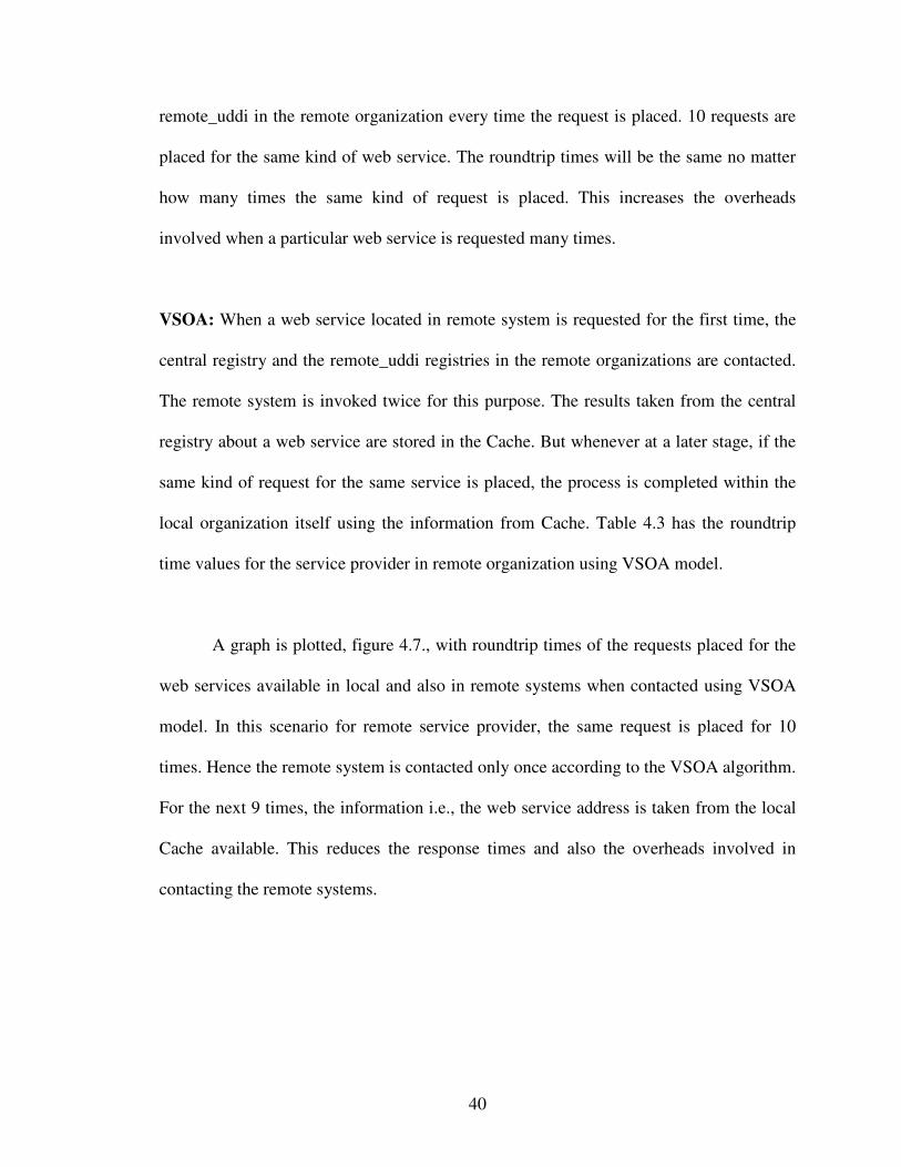
VSOA: When a web service located in remote system is requested for the first time, the
central registry and the remote_uddi registries in the remote organizations are contacted.
The remote system is invoked twice for this purpose. The results taken from the central
registry about a web service are stored in the Cache. But whenever at a later stage, if the
same kind of request for the same service is placed, the process is completed within the
local organization itself using the information from Cache. Table 4.3 has the roundtrip
time values for the service provider in remote organization using VSOA model.
A graph is plotted, figure 4.7., with roundtrip times of the requests placed for the
web services available in local and also in remote systems when contacted using VSOA
model. In this scenario for remote service provider, the same request is placed for 10
times. Hence the remote system is contacted only once according to the VSOA algorithm.
For the next 9 times, the information i.e., the web service address is taken from the local
Cache available. This reduces the response times and also the overheads involved in
contacting the remote systems.

41
Host Port
ResponseSize
(bytes)Delay(ms) Total Roundtrip Time (ms) for the requests placed
TotalAvg
# 1 # 2 # 3 # 4 # 5 # 6 # 7 # 8 # 9 # 10localhost 7080 622 98 7395 7896 6657 8025 9907 5994 6727 7439 8442 7742localhost 7080 623 98 7536 9053 7496 8445 9030 6919 7184 7195 7097 7754localhost 7080 623 98 6442 8821 7530 6215 8751 8919 6657 7541 8410 7145localhost 7080 622 98 6964 7184 9354 8090 6446 7336 6932 8151 7530 8333localhost 7080 624 98 9262 6421 8764 7909 8209 7963 6715 8634 8690 8596localhost 7080 625 98 6617 7321 8410 6963 7986 7309 8554 6519 8090 7343localhost 7080 622 98 8238 7221 9743 7576 9641 7195 7320 7282 6062 7236localhost 7080 624 98 9302 8530 7901 8690 7097 7545 7354 6473 5530 8063localhost 7080 624 98 8473 7443 8473 6922 6062 8661 7671 6941 6085 7617localhost 7080 626 98 7211 7097 7617 8863 8221 8234 6443 7443 5996 7986
avg 7744.0 7698.7 8194.5 7769.8 8135.0 7607.5 7155.7 7361.8 7193.2 7781.5 7664.2stddev 1029.0 851.1 937.1 850.5 1284.6 866.9 621.2 666.5 1197.9 472.9 877.8
Table 4.2: ESOA – Web Service in remote DB2
Requestsplaced Host Port
ResponseSize
(bytes) Total Roundtrip Time (ms) AVG STDDEV1 localhost 7080 626 8442 7211 6617 7097 8209 6932 7530 7901 6421 6223 7258.3 753.62 localhost 7080 622 1187 945 1054 1276 863 1238 1309 1265 1094 969 1120.0 157.83 localhost 7080 622 1284 876 1165 1076 945 1058 1297 978 1007 986 1067.2 141.14 localhost 7080 629 1188 1285 1154 1134 1007 1234 993 954 943 1010 1090.2 123.55 localhost 7080 625 1094 1076 1085 967 1176 1187 945 834 986 1187 1053.7 118.26 localhost 7080 629 969 1165 1287 1097 1122 986 1143 1262 925 1065 1102.1 120.17 localhost 7080 629 1000 1281 890 1054 1238 964 929 1036 1187 1198 1077.7 138.38 localhost 7080 626 1109 1031 963 1293 1109 1297 1198 1309 1024 1276 1160.9 130.39 localhost 7080 626 1281 1094 1189 974 895 912 993 1096 1123 1165 1072.2 125.810 localhost 7080 629 890 1298 1387 935 1053 913 945 1104 1010 914 1044.9 172.1
1704.7 198.1Table 4.3: VSOA – Web Service available in remote system
42
Response Times in VSOA using Cache
0.0
1000.0
2000.0
3000.0
4000.0
5000.0
6000.0
7000.0
8000.0
1 2 3 4 5 6 7 8 9 10
No. of Requests placed
Ro
un
dtr
ipT
imes
(ms)
Web Services located in local org
Web Services located in remote org
Figure 4.7: Roundtrip time vs. no. of requests placed using VSOA algorithm
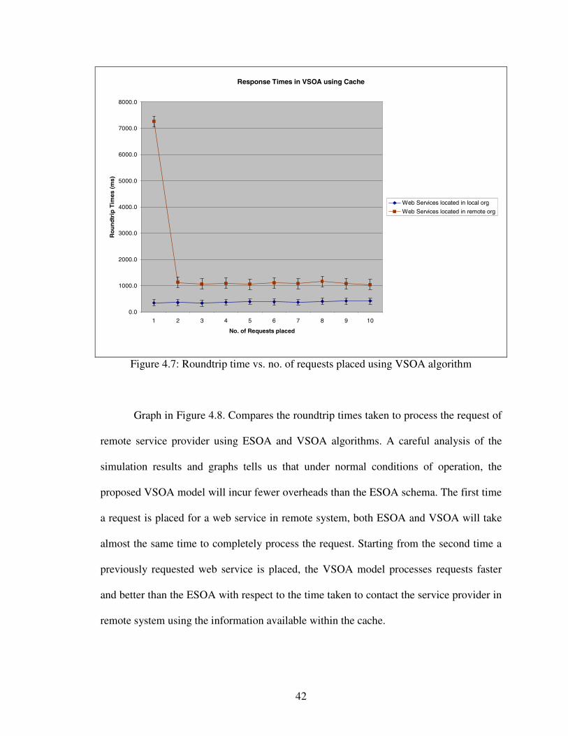
Graph in Figure 4.8. Compares the roundtrip times taken to process the request of
remote service provider using ESOA and VSOA algorithms. A careful analysis of the
simulation results and graphs tells us that under normal conditions of operation, the
proposed VSOA model will incur fewer overheads than the ESOA schema. The first time
a request is placed for a web service in remote system, both ESOA and VSOA will take
almost the same time to completely process the request. Starting from the second time a
previously requested web service is placed, the VSOA model processes requests faster
and better than the ESOA with respect to the time taken to contact the service provider in
remote system using the information available within the cache.
43
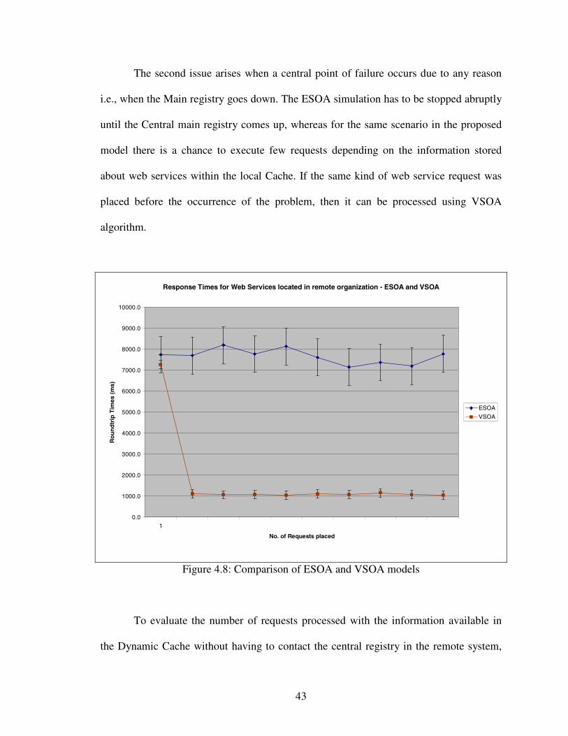
The second issue arises when a central point of failure occurs due to any reason
i.e., when the Main registry goes down. The ESOA simulation has to be stopped abruptly
until the Central main registry comes up, whereas for the same scenario in the proposed
model there is a chance to execute few requests depending on the information stored
about web services within the local Cache. If the same kind of web service request was
placed before the occurrence of the problem, then it can be processed using VSOA
algorithm.
Response Times for Web Services located in remote organization - ESOA and VSOA
0.0
1000.0
2000.0
3000.0
4000.0
5000.0
6000.0
7000.0
8000.0
9000.0
10000.0
1
No. of Requests placed
Ro
un
dtr
ipT
imes
(ms)
ESOA
VSOA
Figure 4.8: Comparison of ESOA and VSOA models
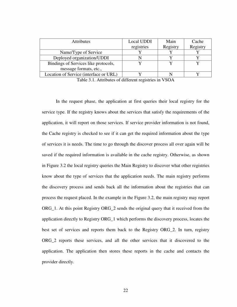
To evaluate the number of requests processed with the information available in
the Dynamic Cache without having to contact the central registry in the remote system,
44
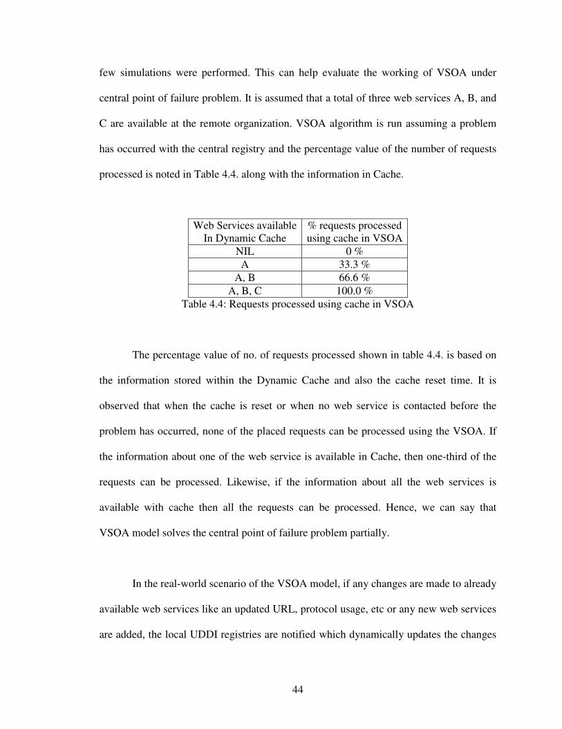
few simulations were performed. This can help evaluate the working of VSOA under
central point of failure problem. It is assumed that a total of three web services A, B, and
C are available at the remote organization. VSOA algorithm is run assuming a problem
has occurred with the central registry and the percentage value of the number of requests
processed is noted in Table 4.4. along with the information in Cache.
Web Services availableIn Dynamic Cache
% requests processedusing cache in VSOA
NIL 0 %A 33.3 %
A, B 66.6 %A, B, C 100.0 %
Table 4.4: Requests processed using cache in VSOA
The percentage value of no. of requests processed shown in table 4.4. is based on
the information stored within the Dynamic Cache and also the cache reset time. It is
observed that when the cache is reset or when no web service is contacted before the
problem has occurred, none of the placed requests can be processed using the VSOA. If
the information about one of the web service is available in Cache, then one-third of the
requests can be processed. Likewise, if the information about all the web services is
available with cache then all the requests can be processed. Hence, we can say that
VSOA model solves the central point of failure problem partially.
In the real-world scenario of the VSOA model, if any changes are made to already
available web services like an updated URL, protocol usage, etc or any new web services
are added, the local UDDI registries are notified which dynamically updates the changes
45
in the Main registry. Unlike in the simulation model, the cache size will not be reset. A
limit is set to the cache size. If its maximum size is reached then replacement strategies
like LRU can be used to save the information about newly accessed web services. The
patterns of the graphs with the real-world results for both the models discussed will be
the same as shown in simulations. There will be a wide range of results obtained as there
will be multiple partner organizations each providing more than one service within a
virtual organization. Furthermore, the different services will be using different protocol
bindings. As the number of service providers increases, there may exists a situation
where one web service will be provided by multiple providers located in different
organizations. Then some other algorithms need to be developed to select the best
provider available from the set of choices in the cache.
46
CHAPTER V
CONCLUSIONS
Four different types of simulations are run for each model discussed i.e., ESOA and
VSOA. The roundtrip times to execute a request placed for a web service located in the
local system are the same for both ESOA and VSOA architectures. For requests placed
for a web service located in a remote system, the performance of the proposed Virtual
Service-Oriented Architecture is better when compared to the Extended Service-Oriented
Architecture. The performance is measured in terms of the time taken to process the
request. The VSOA algorithm also supports the processing of the requests placed even
when a central point of failure occurs. However, there are few limitations to our
simulation. The information stored in the Cache is not updated on a regular basis. There
may be chances that the web service address stored in the Cache is moved to some other
URL or no longer available. In such situations, the request placed cannot be satisfied.
Secondly, since the simulation depends on the communication between different
environments, it is vulnerable to different types of errors and problems. There were
situations where we incurred problems due to the firewalls and antivirus software.
47
A considerable amount of work can be done to improve the performance measures of the
VSOA architecture. The amount of cache memory needed to satisfy web service
requirements has not been explored. Issues such a cache replacement strategies have not
been investigated. In future a real-time architecture should be developed to overcome the
drawbacks of the existing systems in SOA. The problem of trust in SOA remains largely
unexplored.
48
APPENDIX
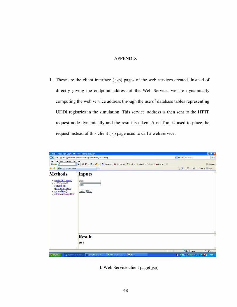
I. These are the client interface (.jsp) pages of the web services created. Instead of
directly giving the endpoint address of the Web Service, we are dynamically
computing the web service address through the use of database tables representing
UDDI registries in the simulation. This service_address is then sent to the HTTP
request node dynamically and the result is taken. A netTool is used to place the
request instead of this client .jsp page used to call a web service.
I. Web Service client page(.jsp)
49
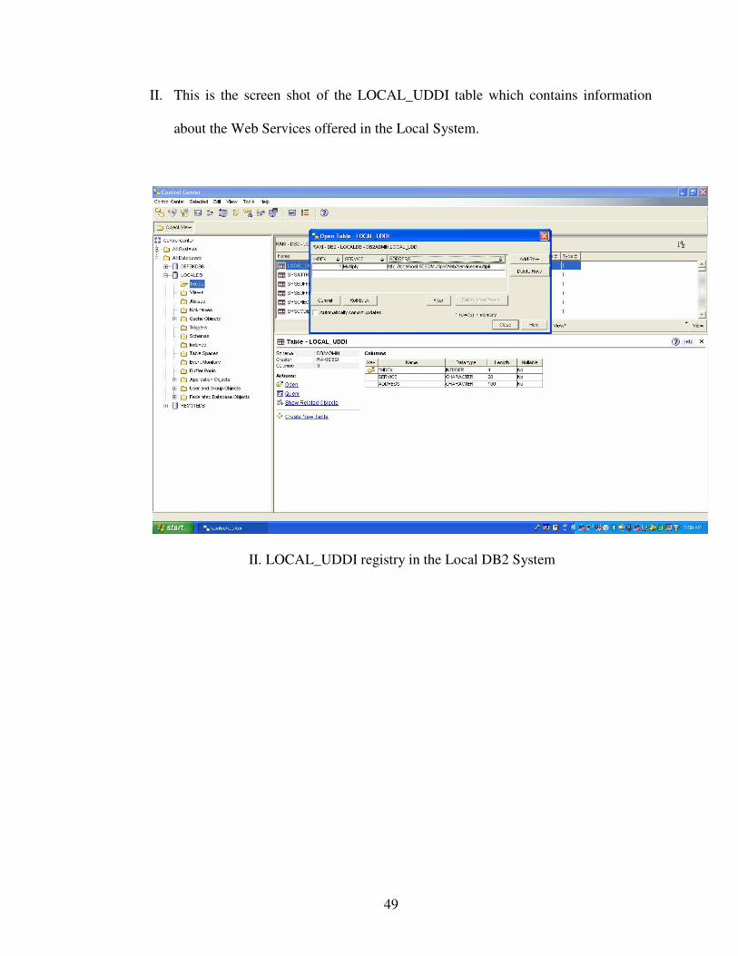
II. This is the screen shot of the LOCAL_UDDI table which contains information
about the Web Services offered in the Local System.
II. LOCAL_UDDI registry in the Local DB2 System
50
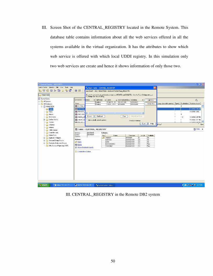
III. Screen Shot of the CENTRAL_REGISTRY located in the Remote System. This
database table contains information about all the web services offered in all the
systems available in the virtual organization. It has the attributes to show which
web service is offered with which local UDDI registry. In this simulation only
two web services are create and hence it shows information of only those two.
III. CENTRAL_REGISTRY in the Remote DB2 system
51
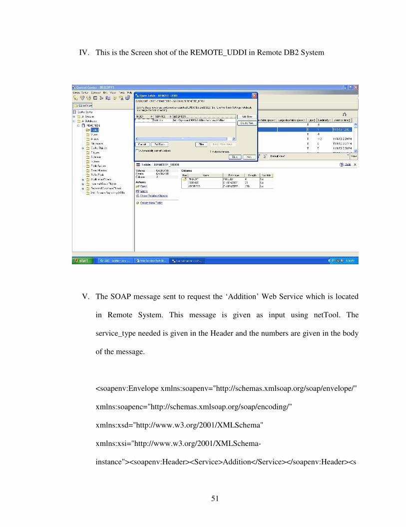
IV. This is the Screen shot of the REMOTE_UDDI in Remote DB2 System
V. The SOAP message sent to request the ‘Addition’ Web Service which is located
in Remote System. This message is given as input using netTool. The
service_type needed is given in the Header and the numbers are given in the body
of the message.
<soapenv:Envelope xmlns:soapenv="http://schemas.xmlsoap.org/soap/envelope/"
xmlns:soapenc="http://schemas.xmlsoap.org/soap/encoding/"
xmlns:xsd="http://www.w3.org/2001/XMLSchema"
xmlns:xsi="http://www.w3.org/2001/XMLSchema-
instance"><soapenv:Header><Service>Addition</Service></soapenv:Header><s
52
oapenv:Body><p565:add
xmlns:p565="http://ibm.com"><i>12.0</i><j>13.0</j></p565:add></soapenv:Bo
dy></soapenv:Envelope>
VI. The SOAP message sent to request the ‘Multiply’ Web Service which is located
in Local System. This message is given as input using the netTool. The
service_type needed is given in the Header and the numbers are given in the body
of the message.
<soapenv:Envelope xmlns:soapenv="http://schemas.xmlsoap.org/soap/envelope/"
xmlns:soapenc="http://schemas.xmlsoap.org/soap/encoding/"
xmlns:xsd="http://www.w3.org/2001/XMLSchema"
xmlns:xsi="http://www.w3.org/2001/XMLSchema-
instance"><soapenv:Header><Service>Multiply</Service></soapenv:Header><s
oapenv:Body><p565:mult
xmlns:p565="http://ibm.com"><i>10.0</i><j>20.0</j></p565:mult></soapenv:B
ody></soapenv:Envelope>
53
REFERENCES
[1] Keen M., Acharya A., Bishop S., Hopkins A., et al., Patterns: Implementing an SOA
using an Enterprise Service Bus, IBM Redbooks publications, July 2004
[2] Hanson J., Enterprise Service Bus,
http://www.sonicsoftware.com/solutions/soa_enterprise/enterprise_service_bus/index.ssp
[last accessed - July 10, 2006]
[3] Martin D., OWL-S: Semantic Markup for Web Services,
http://www.daml.org/services/owl-s/1.0/owl-s.html, [last accessed - April 30, 2006]
[4] Keen M., Bond J., Denman J., Foster S., et al., Patterns: Integrating Enterprise Service
Buses in a Service-Oriented Architecture, IBM Redbooks publications, November 2005
[5] Endrei M., Ang J., Arsanjani A., Chua S., et al., Service-Oriented Architecture and
Web Services, IBM Redbooks publications, April 2004
[6] Schmidt M. T., Hutchison, B., Lambros P., Phippen R., “The Enterprise Service Bus:
Making service-oriented architectural real”, IBM Systems Journal, Vol 44, No 4, pp. 781-
797, 2005
54
[7] Paolucci M., Liu X., Srinivasan N., et al., “Discovery of Information Sources across
Organizational Boundaries”, Proceedings of the 2005 IEEE International Conference on
Services Computing (SCC ’05), pp. 95-102, July 2005
[8] Ding H., Solvberg I., “Exploiting Extended Service-Oriented Architecture for
Federated Digital Libraries”,
http://www.idi.ntnu.no/~haowing/publication/papers/ICADL04.pdf, [last accessed - April
20, 2006]
[9] Korb K.B. and Nicholson A.E., Bayesian Artificial Intelligence, CRC Press, 2004
[10] Cui H., “Build HTTPS Web Services with Rational Application Developer, Part 1:
Web Services and Web Services clients”, IBM Developer Works, pp. 3-10, August 2006
[11] Download of Rational Application Developer V6, http://www-
128.ibm.com/developerworks/downloads/r/rsd/?S_TACT=105AGX15&S_CMP=DLMA
IN, [last accessed – October 18, 2006]
[12] “Websphere Cover Story – ESB Implementation with WAS for z/OS V6”,
http://websphere.sys-con.com/read/222872_p.htm, [last accessed – September,2006]
55
[13] Download page for IBM DB2,
http://www-306.ibm.com/software/data/db2/express/download.html, [last accessed -
October 11, 2006]
[14] Trial: Websphere Application Server, V6.1,
http://www-128.ibm.com/developerworks/downloads/ws/was/index.html, [last accessed -
October 13, 2006]
[15] Kalia, S., Mamas, E., and Spriet, D., “Integrating applications using WebSphere
Business Integration Message Broker V5 -- Part 1: Integration scenario for creating a
Web order processing application”, IBM Developer Works, February 2006
VITA
Anuradha Gasikanti
Candidate for the Degree of
Master of Science
Thesis: INFORMATION DISCOVERY ACROSS ORGANIZATIONALBOUNDARIES THROUGH LOCAL CACHING
Major Field: Computer Science
Biographical:
Personal Data: Born in Hanamkonda, India, On October 13, 1980, the elderdaughter of Rama Rao and Saroja Gasikanti.
Education: Graduated from St. Ann’s High School, Secunderabad, India in May1996; received Bachelor of Technology degree in Computer Science &Information Technology from Jawaharlal Nehru TechnologicalUniversity, Hyderabad, Andhra Pradesh, India in May 2002. Completedthe requirements for the Master of Science degree with a major inComputer Science at Oklahoma State University in December 2006.
Name: Anuradha Gasikanti Date of Degree: December, 2006
Institution: Oklahoma State University Location: Stillwater, Oklahoma
Title of Study: INFORMATION DISCOVERY ACROSS ORGANIZATIONALBOUNDARIES THROUGH LOCAL CACHING
Pages in Study: 55 Candidate for the Degree of Master of Science
Major Field: Computer Science
Scope and Method of Study:
Web services are deployed within the restricted spaces of organizations intranets.There is a need for the creation of virtual organizations where the services offered byone organization should become accessible to other organizations. This requiresexposing IT infrastructures to participants so that the information can flow easilywithin the virtual organization. This proposed model called Virtual Service-OrientedArchitecture, or VSOA, is based on the observation that Universal Description,Discovery and Integration (UDDI) registries are themselves web services. VSOA isalso a way to extend the existing Extended Service-Oriented Architecture modelwhere UDDI registries are required to perform the discovery process of web servicesrepeatedly when the similar request is placed. The proposed architecture makes theInformation discovery process across organizations more flexible and efficient byintroducing a Cache Registry locally within an organization. It is used to store all theresults received by the requestor application about the services it needs and areavailable for retrieval whenever the same kind of request is placed the next time.Caching can significantly improve the response time for such applications by savingthe computed results in a cache, associating the saved results with properties of therequest, and serving subsequent similar requests from the cache. Introduction ofCache also reduces the communication bottleneck introduced in the previous models.
ADVISOR’S APPROVAL: Dr. JOHNSON P. THOMAS