Embed Size (px)
Citation preview
Information Capacity Preserving Translations of Relational
Schemas Using Structural Transformation�
November 1995
External Technical Report
ISSN 0836-0227-95-392
Patrick Martin, James R. Cordy and Rateb Abu-Hamdeh
Dept. of Computing and Information Science
Queen's University at Kingston
Kingston, Ontario
CANADA K7L 3N6
Abstract
Schema translation is one step in the process of schema integration in a multidatabase sys-
tem. We describe an approach to the problem of schema translation which is based on structural
transformation, or syntactic rewrite rules. There are two main advantages with our approach.
First, the translation process can be directly automated using the transformation language TXL.
Second, the correctness of the translation system can be proved using a straightforward anal-
ysis based on information capacity. We develop a set of translation rules to convert relational
schemas to entity-relationship model schemas. We show that the translation rules are informa-
tion capacity preserving and outline how they are automated with TXL.
Topic Area: Interoperability of Heterogeneous Information Systems
1 Introduction
Schema translation is the process of transforming a schema in one data model into a corresponding
schema in a di�erent data model. Historically, the main use of schema translation has been in the
view integration phase of conceptual schema design, which takes several user views representing the
information requirements of di�erent users and integrates them into a single conceptual schema [5].
The user views may be expressed in di�erent data models, in which case they must be translated to
a common data model before performing integration.
Recent interest in the problem of dealing with legacy information systems has renewed interest
in schema translation as it applies to the problems of database integration in multidatabase, or
�The authors thank IBM Canada Ltd., NSERC and ITRC for their support of the research.
1
federated database, systems [14], database migration [11], and schema evolution [16]. As part of
the CORDS Multidatabase System (MDBS) project [2], our main use of schema translation is in
database integration which takes the schemas from a collection of heterogeneous component database
systems, and provides an integrated view of the available data.
The principles for de�ning a schema in a particular data model may be formal, in the sense that
they are inherent to the model, or they may be part of standard design practice. In either case,
the principle used is represented by a distinctive structure in the schema. The structure is in turn
represented by a particular pattern in the DDL de�nition of the schema.
Structural transformation recognizes structures in a source object (schema, program, etc.) and
transforms them into other structures in a target language to produce a translation of the original
object. One can naturally apply it to the problem of schema translation by searching for the
structures in a schema that represent the design rules followed in building the schema and then
transforming them to corresponding structures in order to construct the translated schema. A
structure in the source schema for which there is no corresponding structure in the target data
model means there is a potential loss of information.
Structural transformations of schemas can be implemented as source-to-source syntactic trans-
formations provided that, for each data model,
1. there exists a concrete data description language for expressing schemas in the model and
2. the syntactic structure of the data description language representation of a schema re ects the
logical structure of the schema in some way.
When both these constraints hold, we can implement the structural transformation as a syntactic
transformation from the data description language of the original data model to the data descrip-
tion language of the target data model. Our approach does exactly this, using the TXL source
transformer [9] to implement the syntactic transformations.
In this paper we discuss the development of a set of structural transformation rules, which
we collectively call a translation system, for translating relational schemas to Entity-Relationship
schemas. Such a system may be used to extract the conceptual schema from an exisiting relational
schema or as an intermediate step in the translation to other data models such as an object-oriented
model [1].
2
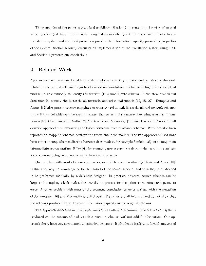
The remainder of the paper is organized as follows. Section 2 presents a brief review of related
work. Section 3 de�nes the source and target data models. Section 4 describes the rules in the
translation system and section 5 presents a proof of the information capacity preserving properties
of the system. Section 6 brie y discusses an implementation of the translation system using TXL
and Section 7 presents our conclusions.
2 Related Work
Approaches have been developed to translate between a variety of data models. Most of the work
related to conceptual schema design has focussed on translation of schemas in high-level conceptual
models, most commonly the entity-relationship (ER) model, into schemas in the three traditional
data models, namely the hierarchical, network, and relational models [12, 15, 22]. Dumpala and
Arora [12] also present reverse mappings to translate relational, hierarchical, and network schemas
to the ER model which can be used to extract the conceptual structure of existing schemas. Johan-
nesson [16], Castellanos and Saltor [7], Markowitz and Makowsky [18], and Davis and Arora [10] all
describe approaches to extracting the logical structure from relational schemas. Work has also been
reported on mapping schemas between the traditional data models. The two approaches used have
been either to map schemas directly between data models, for example Zaniolo [23], or to map to an
intermediate representation. Biller [6], for example, uses a semantic data model as an intermediate
form when mapping relational schemas to network schemas.
One problem with most of these approaches, except the one described by Davis and Arora [10],
is that they require knowledge of the semantics of the source schema, and thus they are intended
to be performed manually by a database designer. In practice, however, source schemas can be
large and complex, which makes the translation process tedious, time consuming, and prone to
error. Another problem with most of the proposed translation schemes is that, with the exception
of Johannesson [16] and Markowitz and Makowsky [18], they are all informal and do not show that
the schemas produced have the same information capacity as the original schemas.
The approach discussed in this paper overcomes both shortcomings. The translation systems
produced can be automated and translate existing schemas without added information. Our ap-
proach does, however, accommodate extended schemas. It also lends itself to a formal analysis of
3
the relative information capacities of the source and target schemas.
3 The Data Models
A data model is a tool that provides an interpretation for data describing real-world situations. It
consists of a set of constructs to describe the structure and constraints of the data, or data de�nition
language (DDL), a set of operations to access the data, or data manipulation language (DML), and,
at least informally, a set of principles for arranging the structures to represent the situation. The
description of a particular database in the DDL is called the database schema.
De�nition 1 A database schema D of data modelM is a pair < S;C > where S is set of distinct
structure descriptions, and C is a set of distinct constraint descriptions, and members of S and C
are expressed in the DDL of M.
3.1 Source Data Model: Relational Model
We present the basic relational concepts and terminology used in the paper. Further details can be
found in any text book, for example Atzeni and De Antonellis [3].
De�nition 2 A relation scheme is a relation name R together with a set of distinct attribute
names, X = fA1; A2; :::; Ang where each Ai belongs to some valid domain Di. To indicate the
relation scheme we write R(A1; A2; :::; An) or R(X).
A relation instance of the relation scheme R is a �nite set of tuples r = ft1; t2; :::; tmg where each
tuple is an ordered list of values t =< v1; v2; :::; vn > and vi 2 Di, 1 <= i <= n, corresponds to the
attribute Ai.
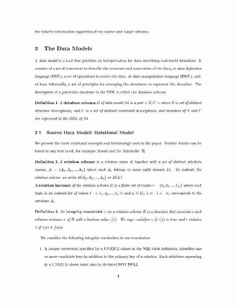
De�nition 3 An integrity constraint on a relation scheme R is a function that associates each
relation instance r of R with a boolean value (r). We say r satis�es if (r) = true and r violates
if (r) = false.
We consider the following integrity constraints in our translation:
1. A unique constraint, speci�ed by a UNIQUE clause in the SQL table de�nition, identi�es one
or more candidate keys in addition to the primary key of a relation. Each attribute appearing
in a UNIQUE clause must also be declared NOT NULL.
4
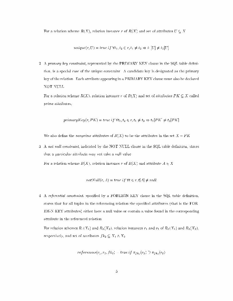
For a relation scheme R(X), relation instance r of R(X) and set of attributes U � X
unique(r; U) = true if 8t1; t2 2 r; t1 6= t2 ) t1[U ] 6= t2[U ]
2. A primary key constraint, represented by the PRIMARY KEY clause in the SQL table de�ni-
tion, is a special case of the unique constraint. A candidate key is designated as the primary
key of the relation. Each attribute appearing in a PRIMARY KEY clause must also be declared
NOT NULL.
For a relation scheme R(X), relation instance r of R(X) and set of attributes PK � X called
prime attributes,
primaryKey(r; PK) = true if 8t1; t2 2 r; t1 6= t2 ) t1[PK] 6= t2[PK]
We also de�ne the nonprime attributes of R(X) to be the attributes in the set X � PK.
3. A not null constraint, indicated by the NOT NULL clause in the SQL table de�nition, states
that a particular attribute may not take a null value.
For a relation scheme R(X), relation instance r of R(X) and attribute A 2 X
notNull(r; A) = true if 8t 2 r; t[A] 6= null
4. A referential constraint, speci�ed by a FOREIGN KEY clause in the SQL table de�nition,
states that for all tuples in the referencing relation the speci�ed attributes (that is the FOR-
EIGN KEY attributes) either have a null value or contain a value found in the corresponding
attribute in the referenced relation.
For relation schemes R1(X1) and R2(X2), relation instances r1 and r2 of R1(X1) and R2(X2),
respectively, and set of attributes fk2 � X1 ^X2
references(r1; r2; fk2) = true if �fk2(r1) � �fk2(r2)
5
where �fki(ri) is the projection of ri on fki which is ft[fki]jt 2 ri; i 2 f1; 2gg.
For relation scheme R(X) we de�ne FK = fk1 [ fk2 [ :::[ fkn to be the set of all foreign key
attributes where n is the number of distinct foreign keys in R.
De�nition 4 A database schema D for the relational model is a pair < R;C > where R is set
of relation schemes with distinct names, and C is a set of integrity constraints.
A database instance (or simply database) on a database schema D with R = fR1(X1); R2(X2); :::; Rn(Xn)g
is a set of relation instances r = fr1; r2; :::rng where each instance ri is de�ned on the corresponding
scheme Ri and satis�es the corresponding integrity constraints in C.
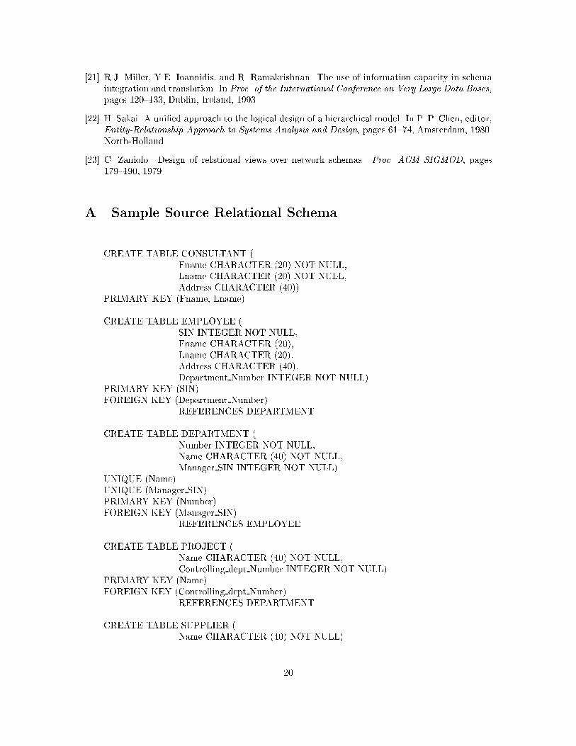
An example source relational schema is given in Appendix A.
3.2 Target Data Model: Entity-Relationship Model
The target data model for our translation is the Entity-Relationship model [8]. As explained earlier,
we chose the ER model because it can serve as the basis for further work on extracting conceptual
schemas or as an intermediate stage in translations to other data models.
The ER model does not have a generally accepted DDL. We chose to represent the ER schema
information as a set of Prolog facts which we call a schema factbase. A fact represents a single piece
of information and is de�ned as follows.
De�nition 5 A schema fact p(A1; A2; :::; An) is composed of a predicate symbol p and a list of
arguments A1; A2; :::; An where n >= 1. The predicates correspond to constructs in the ER model
and the arguments are either names from the source schema or constants.
De�nition 6 A schema factbase F for the ER model is a triple < E;R;C > where E, R and C
are the sets of facts describing entity types, relationship types and integrity constraints, respectively.
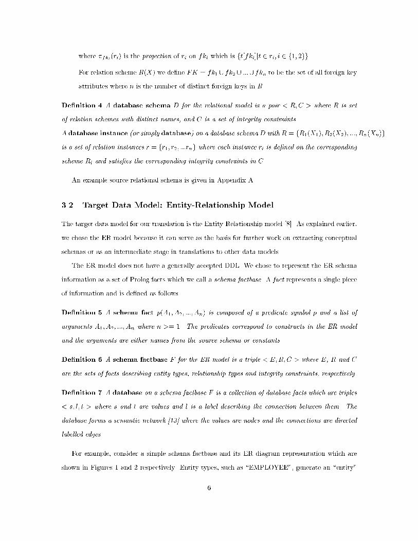
De�nition 7 A database on a schema factbase F is a collection of database facts which are triples
< s; l; t > where s and t are values and l is a label describing the connection between them. The
database forms a semantic network [13] where the values are nodes and the connections are directed
labelled edges.
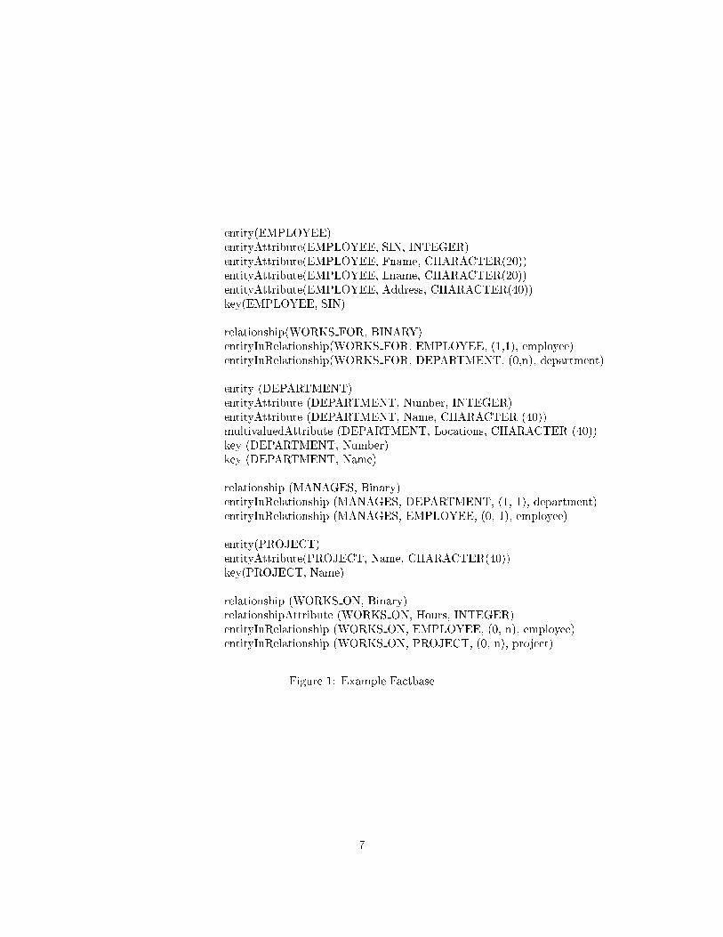
For example, consider a simple schema factbase and its ER diagram representation which are
shown in Figures 1 and 2 respectively. Entity types, such as \EMPLOYEE", generate an \entity"
6
entity(EMPLOYEE)entityAttribute(EMPLOYEE, SIN, INTEGER)entityAttribute(EMPLOYEE, Fname, CHARACTER(20))entityAttribute(EMPLOYEE, Lname, CHARACTER(20))entityAttribute(EMPLOYEE, Address, CHARACTER(40))key(EMPLOYEE, SIN)
relationship(WORKS FOR, BINARY)entityInRelationship(WORKS FOR, EMPLOYEE, (1,1), employee)entityInRelationship(WORKS FOR, DEPARTMENT, (0,n), department)
entity (DEPARTMENT)entityAttribute (DEPARTMENT, Number, INTEGER)entityAttribute (DEPARTMENT, Name, CHARACTER (40))multivaluedAttribute (DEPARTMENT, Locations, CHARACTER (40))key (DEPARTMENT, Number)key (DEPARTMENT, Name)
relationship (MANAGES, Binary)entityInRelationship (MANAGES, DEPARTMENT, (1, 1), department)entityInRelationship (MANAGES, EMPLOYEE, (0, 1), employee)
entity(PROJECT)entityAttribute(PROJECT, Name, CHARACTER(40))key(PROJECT, Name)
relationship (WORKS ON, Binary)relationshipAttribute (WORKS ON, Hours, INTEGER)entityInRelationship (WORKS ON, EMPLOYEE, (0, n), employee)entityInRelationship (WORKS ON, PROJECT, (0, n), project)
Figure 1: Example Factbase
7

Figure 2: Example ER Schema
8
fact, an \entityAttribute" fact for each attribute which identi�es the name and type of the attribute,
and a \key" fact for each key of the entity type. We assume that, in the case of more than one key
fact, the �rst fact represents the primary key.
Relationship types, such as \WORKS ON", generates a relationship fact which contains the
arity of the relationship, a \relationshipAttribute" fact for each attribute of the relationship, and
an \entityInRelationship" fact for each entity type participating in the relationship which identi�es
the minimum and maximum cardinalities and the role of the entity type in the relationship. The
participation (that is, total or partial) of the entity type in the relationship may be inferred from
the minimum cardinality. Other types of facts, which are shown in the example, may be generated
for other ER constructs such as weak entities and composite attributes. Examples of these types of
facts appear in Appendix B.
A portion of a possible database on the schema factbase given in Figure 1 is shown in Figure 3.
The nodes may be actual attribute values, unique identi�ers for instances of entity types, relationship
types and system types such as ROLES, and type names. The edges represent connections taken
from the schema, for example attribute names or system-de�ned connections such as \instance" and
\plays".
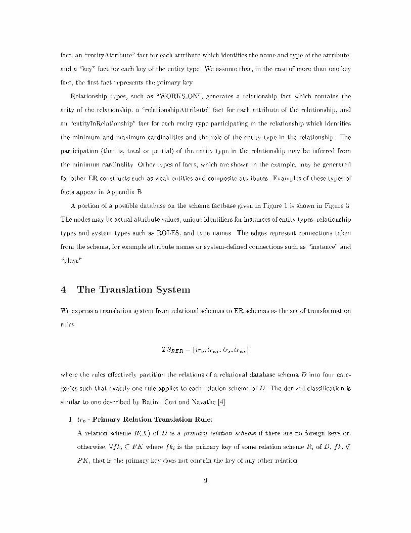
4 The Translation System
We express a translation system from relational schemas to ER schemas as the set of transformation
rules
TSRER = ftrp; trwp; trs; trwsg
where the rules e�ectively partition the relations of a relational database schema D into four cate-
gories such that exactly one rule applies to each relation scheme of D. The derived classi�cation is
similar to one described by Batini, Ceri and Navathe [4].
1. trp - Primary Relation Translation Rule:
A relation scheme R(X) of D is a primary relation scheme if there are no foreign keys or,
otherwise, 8fki � FK where fki is the primary key of some relation scheme Ri of D, fki 6�
PK, that is the primary key does not contain the key of any other relation.
9

Figure 3: Example Database
10
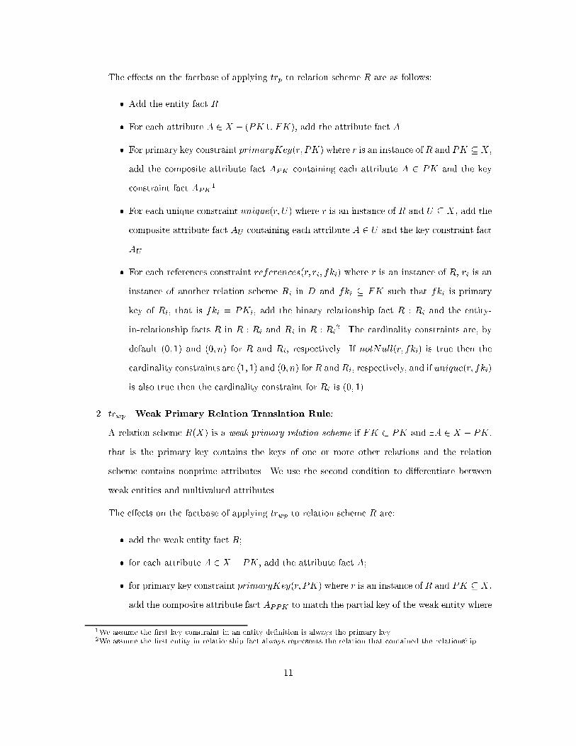
The e�ects on the factbase of applying trp to relation scheme R are as follows:
� Add the entity fact R.
� For each attribute A 2 X � (PK [ FK), add the attribute fact A.
� For primary key constraint primaryKey(r; PK) where r is an instance of R and PK � X ,
add the composite attribute fact APK containing each attribute A 2 PK and the key
constraint fact APK1.
� For each unique constraint unique(r; U) where r is an instance of R and U � X , add the
composite attribute fact AU containing each attribute A 2 U and the key constraint fact
AU .
� For each references constraint references(r; ri; fki) where r is an instance of R, ri is an
instance of another relation scheme Ri in D and fki � FK such that fki is primary
key of Ri, that is fki = PKi, add the binary relationship fact R : Ri and the entity-
in-relationship facts R in R : Ri and Ri in R : Ri2. The cardinality constraints are, by
default (0; 1) and (0; n) for R and Ri, respectively. If notNull(r; fki) is true then the
cardinality constraints are (1; 1) and (0; n) for R and Ri, respectively, and if unique(r; fki)
is also true then the cardinality constraint for Ri is (0; 1).
2. trwp - Weak Primary Relation Translation Rule:
A relation scheme R(X) is a weak primary relation scheme if FK � PK and 9A 2 X � PK,
that is the primary key contains the keys of one or more other relations and the relation
scheme contains nonprime attributes. We use the second condition to di�erentiate between
weak entities and multivalued attributes.
The e�ects on the factbase of applying trwp to relation scheme R are:
� add the weak entity fact R;
� for each attribute A 2 X � PK, add the attribute fact A;
� for primary key constraint primaryKey(r; PK) where r is an instance of R and PK � X ,
add the composite attribute fact APPK to match the partial key of the weak entity where
1We assume the �rst key constraint in an entity de�nition is always the primary key.
2We assume the �rst entity-in-relationship fact always represents the relation that contained the relationship.
11
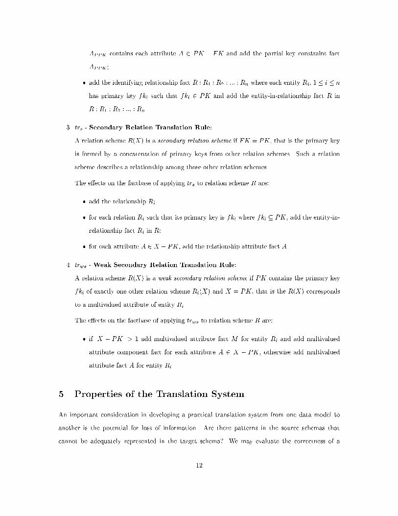
APPK contains each attribute A 2 PK � FK and add the partial key constraint fact
APPK ;
� add the identifying relationship fact R : R1 : R2 : ::: : Rn where each entity Ri, 1 � i � n
has primary key fki such that fki 2 PK and add the entity-in-relationship fact R in
R : R1 : R2 : ::: : Rn.
3. trs - Secondary Relation Translation Rule:
A relation scheme R(X) is a secondary relation scheme if FK = PK, that is the primary key
is formed by a concatenation of primary keys from other relation schemes. Such a relation
scheme describes a relationship among those other relation schemes.
The e�ects on the factbase of applying trs to relation scheme R are:
� add the relationship R;
� for each relation Ri such that its primary key is fki where fki � PK, add the entity-in-
relationship fact Ri in R;
� for each attribute A 2 X � PK, add the relationship attribute fact A.
4. trws - Weak Secondary Relation Translation Rule:
A relation scheme R(X) is a weak secondary relation scheme if PK contains the primary key
fki of exactly one other relation scheme Ri(X) and X = PK, that is the R(X) corresponds
to a multivalued attribute of entity Ri.
The e�ects on the factbase of applying trws to relation scheme R are:
� if jX � PKj > 1 add multivalued attribute fact M for entity Ri and add multivalued
attribute component fact for each attribute A 2 X � PK, otherwise add multivalued
attribute fact A for entity Ri.
5 Properties of the Translation System
An important consideration in developing a practical translation system from one data model to
another is the potential for loss of information. Are there patterns in the source schemas that
cannot be adequately represented in the target schema? We may evaluate the correctness of a
12
translation system based on the relative information capacities of the source and target schemas,
that is, do the source and target schemas model the same real world information?
An analysis of the correctness of a translation system should also consider the operational goals
of the schema translation. For example, if a multidatabase system must support querying of the
source database through the target schema, then a correct translation system should ensure that
all data in the source database maps to a representation under the target schema. If, however, the
multidatabase system must also support updates of the source database through the target schema,
a correct translation system must ensure that data maps to representations in both directions.
A strength of our approach is that the correctness of translation systems expressed as a set
of syntactic rewrite rules may be evaluated in a rigorous manner. We present an analysis of the
Relational-to-ER system TSRER as an example. We �rst give a set of de�nitions to establish
our notion of correctness based on information capacity. We next provide a collection of lemmas
which, in combination, prove the main result of the section, namely that the translation system
TSRER is information capacity preserving and hence correct. The proofs of the lemmas are given
in Appendix C.
The information capacity of a database schema D1 determines the set of valid instances I(D1) of
that schema [21]. Intuitively, we say that a database schema D2 has a greater information capacity
than a schema D1 if every instance i 2 I(D1) can be mapped to some instance j 2 I(D2) without
loss of information, that is we can recover the original instance from its image under the mapping.
We de�ne these concepts more precisely below.
De�nition 8 An information capacity preserving mapping between the instances of two database
schemas D1 and D2 is a total, injective function f : I(D1)! I(D2).
De�nition 9 If D1 and D2 are two database schemas such that f : I(D1)! I(D2) is an information
capacity preserving mapping, then D2 dominates D1 via f , denoted D1 � D2.
De�nition 10 Let D1 and D2 be sets of schemas speci�ed in the di�erent data models M1 and
M2, respectively. A translation system T S from D1 to D2 induces the total function F :D1 !D2.
T S is information capacity preserving if for all D 2D1, D � F (D).
De�nition 11 A translation system T S is correct if it is information capacity preserving and if
the operational goal of the system is that the entire database stored under the source schema may be
13
viewed and queried through the target schema.
In our approach to schema translation, a translation system is expressed as a set of independent
syntactic rewrite rules rather than as an algorithm as in most other approaches. The rules are
functions in the mathematical sense, that is they do not produce side-e�ects, and they produce the
same result independent of the order in which they are applied [17]. Thus the proof that a translation
system is information capacity preserving can be reduced to proving that each individual rule is an
information capacity preserving translation, and that the set of rules in the translation system
partition the relation schemes in the source schema so that each relation scheme is translated by
exactly one transformation rule. We assume that good design practices are followed in creating
the source relational database schemas and do not consider poorly designed relation schemes in our
analysis.
Lemma 1 Given relational database schema D =< R;C >, the classi�cation imposed on R by the
translation system TSRER is a partition.
Lemma 2 Given relational database schema D =< R;C >, the syntactic rewrite rule trp is an
information capacity preserving translation on its partition of R.
Lemma 3 Given relational database schema D =< R;C >, the syntactic rewrite rule trwp is an
information capacity preserving translation on its partition of R.
Lemma 4 Given relational database schema D =< R;C >, the syntactic rewrite rule trs is an
information capacity preserving translation on its partition of R.
Lemma 5 Given relational database schema D =< R;C >, the syntactic rewrite rule trws is an
information capacity preserving translation on its partition of R.
Claim 1 The Relational-to-ER translation system TSRER is an information capacity preserving
schema translation.
PROOF: The proof of the claim that the Relational-to-ER translation system TSRER is an infor-
mation capacity preserving schema translation based on the results shown in Lemmas 1 - 5. Lemma
1 ensures that exactly one rule in TSRER applies to every relation scheme Ri in a relational database
schema D. Lemmas 2 - 5 show that each rule in TSRER is information capacity preserving over its
14
subset of the relation schemes in D. Therefore the total translation system is information capacity
preserving.
6 Implementation of the Translation System
Our translation system has been implemented using the TXL transformation system [9]. TXL is a
structural source transformer, which means that
1. both the input and output of the transformation must be in source text form, and
2. the meaning of the source text must somehow be encoded in its syntactic structure.
In practice these two restrictions simply mean that the input and output must be in some formal
(machine processable) language.
TXL is well suited to transformations of the structure of the input rather than just its text.
For example, the transformation between a cascade of nested if statements and an equivalent case
statement is straightforward in TXL, whereas it can be very complex using text-based tools such
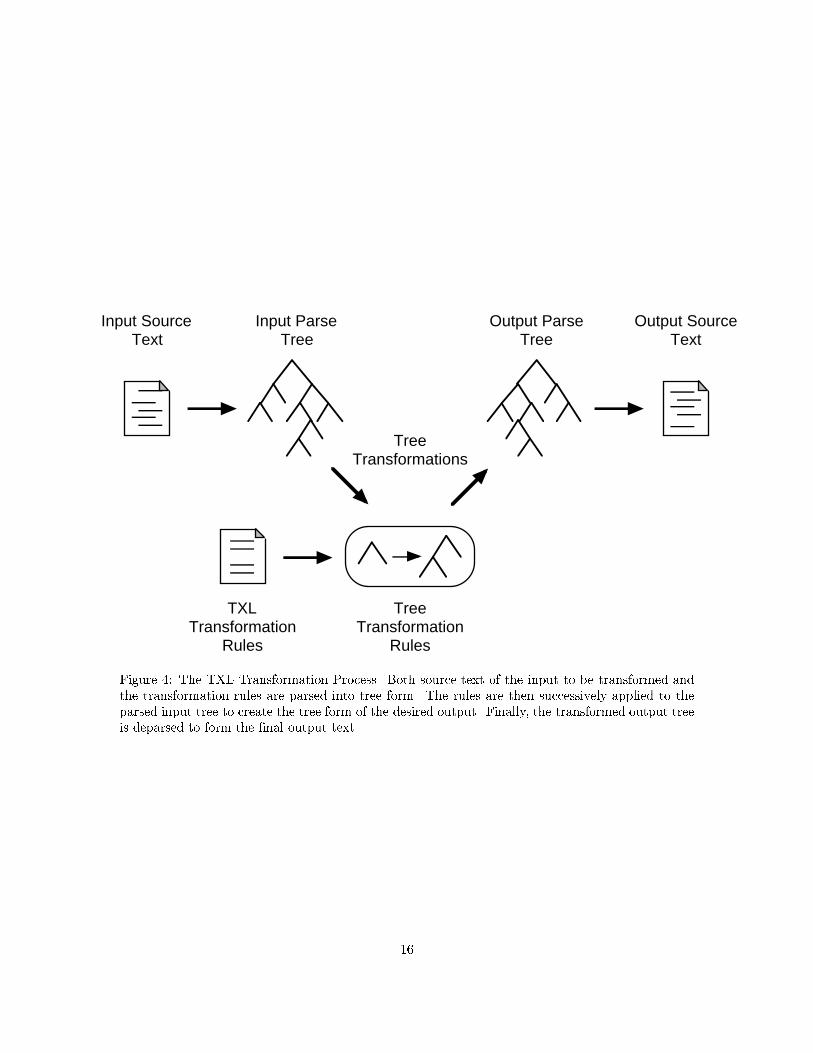
as sed and awk. TXL achieves this simplicity of structural transformation by parsing the input and
output into abstract syntax trees, and implementing the transformations on the trees rather than
the source text itself (Figure 4).
TXL transformations are programmed using sets of rules, each of which speci�es a pattern and a
replacement. The pattern captures the components of the input structure we would like to transform,
and the replacement shows how to rearrange those components into the output. Both are speci�ed
by example, which is to say, in source text form, but are implemented as manipulations of the
corresponding syntax trees as shown in Figure 4.
The TXL implementation of our translation system represents relational schemas by the source
text of their SQL DDL speci�cations, and entity-relationship schemas by the source text of a Prolog
factbase for their ER diagram. The translation system itself is expressed as a set of TXL rules that
transform the syntactic structures of the input DDL to the syntactic structures of the output DDL.
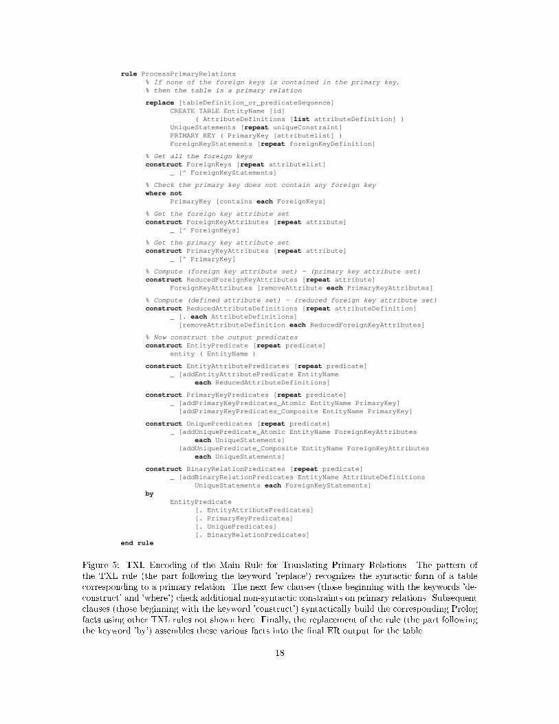
Each of the four main rules in the set has a pattern that syntactically matches the structure of
one of the four kinds of table de�nitions corresponding to primary relations, weak primary relations,
secondary relations or weak secondary relations as described in section 4, and a replacement that
syntactically generates the corresponding Prolog facts (Figure 5).
15
Input SourceText
Input ParseTree
Output ParseTree
Output SourceText
TXLTransformation
Rules
TreeTransformation
Rules
TreeTransformations
Figure 4: The TXL Transformation Process. Both source text of the input to be transformed andthe transformation rules are parsed into tree form. The rules are then successively applied to theparsed input tree to create the tree form of the desired output. Finally, the transformed output treeis deparsed to form the �nal output text.
16
TXL's ability to directly encode the structural patterns on which our translations are based makes
the implementation of new translation systems, once they are designed, relatively straightforward.
7 Summary
Schema translation is important for providing integration and interoperability in multidatabase
systems. Two shortcomings of many of the existing approaches to the problem are that they are not
easily automated and that they lack a formal basis for evaluating the correctness of the resulting
translations. We have discussed an approach based on structural transformation that overcomes
both of these problems.
Structural transformation is a technique for recognizing structures in a source language and
translating them into structures in a target language. The structural transformations are imple-
mented as source-to-source syntactic transformations. As we show in the paper, the technique can
be successfully applied to the problem of schema translation.
Our approach expresses a translation system as a set of independent transformation rules. We
indicate in the paper how one can prove the correctness of a system by showing that the rules
preserve information capacity. We also describe how a translation system can be automated using
the structural transformation language TXL.
We have developed translation systems to transform schema descriptions in representative re-
lational, hierarchical, network, and object-oriented DDLs into an ER factbase representation, and
vice versa. We can compose the translation systems to translate among the various data models.
We plan to continue to study the problem of schema translation and to apply our approach to
automatic query translation. We are also incorporating the TXL implementations of the translation
systems into a suite of tools to support database integration in a prototype multidatabase system [20].
References
[1] R. Abu-hamdeh, J. Cordy, and P. Martin. Schema translation using structural transformation.In Proc. of CASCON'94, IBM Centre for Advanced Studies 1994 Conference, pages 202{215,Toronto, November 1994.
[2] G. Attaluri, D. Bradshaw, N. Coburn, P.-�A. Larson, P. Martin, A. Silbershatz, J. Slonim, andQ. Zhu. The CORDS multidatabase project. IBM Systems Journal, 34(1):39{62, January 1995.
17
rule ProcessPrimaryRelations% If none of the foreign keys is contained in the primary key,% then the table is a primary relation
replace [tableDefinition_or_predicateSequence]CREATE TABLE EntityName [id]
( AttributeDefinitions [list attributeDefinition] ) UniqueStatements [repeat uniqueConstraint]PRIMARY KEY ( PrimaryKey [attributelist] ) ForeignKeyStatements [repeat foreignKeyDefinition]
% Get all the foreign keysconstruct ForeignKeys [repeat attributelist]
_ [^ ForeignKeyStatements]
% Check the primary key does not contain any foreign keywhere not
PrimaryKey [contains each ForeignKeys]
% Get the foreign key attribute setconstruct ForeignKeyAttributes [repeat attribute]
_ [^ ForeignKeys]
% Get the primary key attribute setconstruct PrimaryKeyAttributes [repeat attribute]
_ [^ PrimaryKey]
% Compute (foreign key attribute set) - (primary key attribute set)construct ReducedForeignKeyAttributes [repeat attribute]
ForeignKeyAttributes [removeAttribute each PrimaryKeyAttributes]
% Compute (defined attribute set) - (reduced foreign key attribute set)construct ReducedAttributeDefinitions [repeat attributeDefinition]
_ [. each AttributeDefinitions] [removeAttributeDefinition each ReducedForeignKeyAttributes]
% Now construct the output predicatesconstruct EntityPredicate [repeat predicate]
entity ( EntityName )
construct EntityAttributePredicates [repeat predicate]_ [addEntityAttributePredicate EntityName
each ReducedAttributeDefinitions]
construct PrimaryKeyPredicates [repeat predicate]_ [addPrimaryKeyPredicates_Atomic EntityName PrimaryKey] [addPrimaryKeyPredicates_Composite EntityName PrimaryKey]
construct UniquePredicates [repeat predicate]_ [addUniquePredicate_Atomic EntityName ForeignKeyAttributes
each UniqueStatements] [addUniquePredicate_Composite EntityName ForeignKeyAttributes
each UniqueStatements]
construct BinaryRelationPredicates [repeat predicate]_ [addBinaryRelationPredicates EntityName AttributeDefinitions
UniqueStatements each ForeignKeyStatements]by
EntityPredicate[. EntityAttributePredicates][. PrimaryKeyPredicates][. UniquePredicates][. BinaryRelationPredicates]
end rule
Figure 5: TXL Encoding of the Main Rule for Translating Primary Relations. The pattern ofthe TXL rule (the part following the keyword 'replace') recognizes the syntactic form of a tablecorresponding to a primary relation. The next few clauses (those beginning with the keywords 'de-construct' and 'where') check additional non-syntactic constraints on primary relations. Subsequentclauses (those beginning with the keyword 'construct') syntactically build the corresponding Prologfacts using other TXL rules not shown here. Finally, the replacement of the rule (the part followingthe keyword 'by') assembles these various facts into the �nal ER output for the table.
18
[3] P. Atzeni and V. De Antonellis. Relational Database Theory. The Benjamin/Cummings Pub-lishing Company, Inc., 1993.
[4] C. Batini, S. Ceri, and S. Navathe. Conceptual Database Design: An Entity-Relationship Ap-
proach. The Benjamin/Cummings Publishing Company, Inc., 1992.
[5] C. Batini, M. Lenzerini, and S.B Navathe. A comparative analysis of methodologies for databaseschema integration. ACM Computing Surveys, 18(4):323{364, 1986.
[6] H. Biller. On the equivalence of data base schemas { a semantic approach to data translation.Inf. Syst., 4:35{47, 1979.
[7] M. Castellanos and F. Saltor. Semantic enrichment of database schemas: An object oriented ap-proach. In Proc. of First International Workshop on Interoperability in Multidatabase Systems,pages 71{78, 1991.
[8] P.P. Chen. The entity-relationship model: Towards a uni�ed view of data. ACM Trans. Database
Syst., 1(1), 1970.
[9] J.R. Cordy, C.D. Halpern-Hamu, and E.M. Promislow. TXL: A rapid prototyping system forprogramming language dialects. Computer Languages, 16(1):97{107, 1991.
[10] K. Davis and A. Arora. Converting a relational database model into an entity-relationshipmodel. In S. T. March, editor, Entity-Relationship Approach, pages 271{285, Amsterdam,1988. North-Holland.
[11] P. Drew. On database technology for information system migration and evolution. In Proc.
of the Workshop on Interoperability of Database Systems and Database Applications, pages121{131, Fribourg, 1993.
[12] S. Dumpala and S. Arora. Schema translation using the entity-relationship approach. In P. P.Chen, editor, Entity-Relationship Approach to Information Modeling and Analysis, pages 337{356, Amsterdam, 1983. North-Holland.
[13] R. Frost. Introduction to Knowledge Base Systems. Macmillan Publishing Co., 1986.
[14] D. Hsiao. Tutorial on federated databases and systems (part I). The VLDB Journal, 1(1):127{179, 1992.
[15] J. Iossiphidis. A translator to convert the DDL of ERM to the DDL of system 2000. In P. P.
Chen, editor, Entity-Relationship Approach to Systems Analysis and Design, pages 477{504,Amsterdam, 1980. North-Holland.
[16] P. Johannesson. A method for transforming relational schemas into conceptual schemas. InProc. of the International Conference on Data Engineering, pages 190{201, Houston, 1994.
[17] A. Malton. The denotational semantics of a functional tree-manipulation language. Computer
Languages, 19(3):157{168, 1993.
[18] V. Markowitz and J. Makowsky. Identifying extended entity-relationship object structures inrelational schemas. IEEE Trans. on Software Engineering, 16(8):777{790, 1990.
[19] P. Martin, J. Cordy, and R. Abu-hamdeh. A general approach to schema translation usingstructural transformation. in preparation.
[20] P. Martin and W. Powley. Database integration using multidatabase views. In Proc. of CAS-
CON'93, IBM Centre for Advanced Studies 1993 Conference, pages 779{788, Toronto, 1993.
19
[21] R.J. Miller, Y.E. Ioannidis, and R. Ramakrishnan. The use of information capacity in schemaintegration and translation. In Proc. of the International Conference on Very Large Data Bases,pages 120{133, Dublin, Ireland, 1993.
[22] H. Sakai. A uni�ed approach to the logical design of a hierarchical model. In P. P. Chen, editor,Entity-Relationship Approach to Systems Analysis and Design, pages 61{74, Amsterdam, 1980.North-Holland.
[23] C. Zaniolo. Design of relational views over network schemas. Proc. ACM SIGMOD, pages179{190, 1979.
A Sample Source Relational Schema
CREATE TABLE CONSULTANT (Fname CHARACTER (20) NOT NULL,Lname CHARACTER (20) NOT NULL,Address CHARACTER (40))
PRIMARY KEY (Fname, Lname)
CREATE TABLE EMPLOYEE (SIN INTEGER NOT NULL,Fname CHARACTER (20),Lname CHARACTER (20),Address CHARACTER (40),Department Number INTEGER NOT NULL)
PRIMARY KEY (SIN)FOREIGN KEY (Department Number)
REFERENCES DEPARTMENT
CREATE TABLE DEPARTMENT (Number INTEGER NOT NULL,Name CHARACTER (40) NOT NULL,Manager SIN INTEGER NOT NULL)
UNIQUE (Name)UNIQUE (Manager SIN)PRIMARY KEY (Number)FOREIGN KEY (Manager SIN)
REFERENCES EMPLOYEE
CREATE TABLE PROJECT (Name CHARACTER (40) NOT NULL,Controlling dept Number INTEGER NOT NULL)
PRIMARY KEY (Name)FOREIGN KEY (Controlling dept Number)
REFERENCES DEPARTMENT
CREATE TABLE SUPPLIER (Name CHARACTER (40) NOT NULL)
20
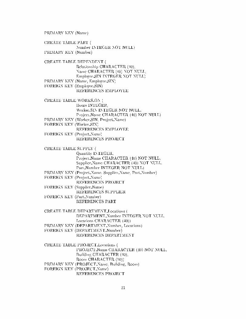
PRIMARY KEY (Name)
CREATE TABLE PART (Number INTEGER NOT NULL)
PRIMARY KEY (Number)
CREATE TABLE DEPENDENT (Relationship CHARACTER (40),Name CHARACTER (40) NOT NULL,Employee SIN INTEGER NOT NULL)
PRIMARY KEY (Name, Employee SIN)FOREIGN KEY (Employee SIN)
REFERENCES EMPLOYEE
CREATE TABLE WORKS ON (Hours INTEGER,Worker SIN INTEGER NOT NULL,Project Name CHARACTER (40) NOT NULL)
PRIMARY KEY (Worker SIN, Project Name)FOREIGN KEY (Worker SIN)
REFERENCES EMPLOYEEFOREIGN KEY (Project Name)
REFERENCES PROJECT
CREATE TABLE SUPPLY (Quantity INTEGER,Project Name CHARACTER (40) NOT NULL,Supplier Name CHARACTER (40) NOT NULL,Part Number INTEGER NOT NULL)
PRIMARY KEY (Project Name, Supplier Name, Part Number)FOREIGN KEY (Project Name)
REFERENCES PROJECTFOREIGN KEY (Supplier Name)
REFERENCES SUPPLIERFOREIGN KEY (Part Number)
REFERENCES PART
CREATE TABLE DEPARTMENT Locations (DEPARTMENT Number INTEGER NOT NULL,Locations CHARACTER (40))
PRIMARY KEY (DEPARTMENT Number, Locations)FOREIGN KEY (DEPARTMENT Number)
REFERENCES DEPARTMENT
CREATE TABLE PROJECT Locations (PROJECT Name CHARACTER (40) NOT NULL,Building CHARACTER (40),Room CHARACTER (10))
PRIMARY KEY (PROJECT Name, Building, Room)FOREIGN KEY (PROJECT Name)
REFERENCES PROJECT
21
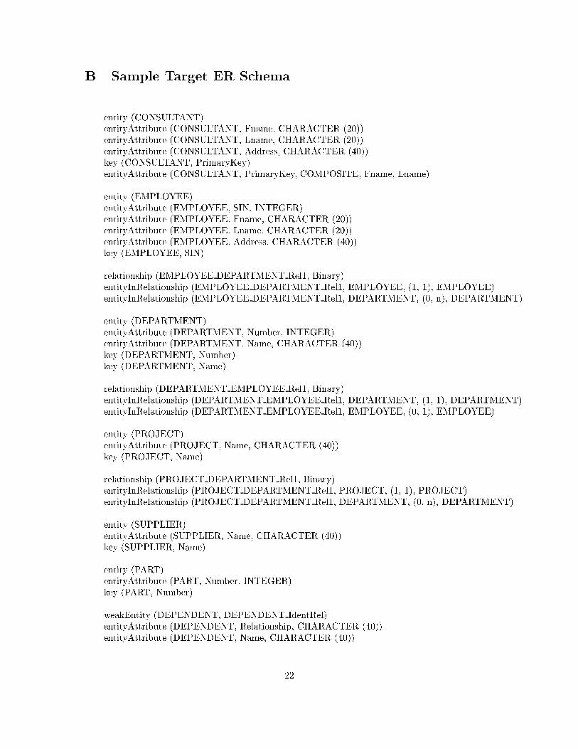
B Sample Target ER Schema
entity (CONSULTANT)entityAttribute (CONSULTANT, Fname, CHARACTER (20))entityAttribute (CONSULTANT, Lname, CHARACTER (20))entityAttribute (CONSULTANT, Address, CHARACTER (40))key (CONSULTANT, PrimaryKey)entityAttribute (CONSULTANT, PrimaryKey, COMPOSITE, Fname, Lname)
entity (EMPLOYEE)entityAttribute (EMPLOYEE, SIN, INTEGER)entityAttribute (EMPLOYEE, Fname, CHARACTER (20))entityAttribute (EMPLOYEE, Lname, CHARACTER (20))entityAttribute (EMPLOYEE, Address, CHARACTER (40))key (EMPLOYEE, SIN)
relationship (EMPLOYEE DEPARTMENT Rel1, Binary)entityInRelationship (EMPLOYEE DEPARTMENT Rel1, EMPLOYEE, (1, 1), EMPLOYEE)entityInRelationship (EMPLOYEE DEPARTMENT Rel1, DEPARTMENT, (0, n), DEPARTMENT)
entity (DEPARTMENT)entityAttribute (DEPARTMENT, Number, INTEGER)entityAttribute (DEPARTMENT, Name, CHARACTER (40))key (DEPARTMENT, Number)key (DEPARTMENT, Name)
relationship (DEPARTMENT EMPLOYEE Rel1, Binary)entityInRelationship (DEPARTMENT EMPLOYEE Rel1, DEPARTMENT, (1, 1), DEPARTMENT)entityInRelationship (DEPARTMENT EMPLOYEE Rel1, EMPLOYEE, (0, 1), EMPLOYEE)
entity (PROJECT)entityAttribute (PROJECT, Name, CHARACTER (40))key (PROJECT, Name)
relationship (PROJECT DEPARTMENT Rel1, Binary)entityInRelationship (PROJECT DEPARTMENT Rel1, PROJECT, (1, 1), PROJECT)entityInRelationship (PROJECT DEPARTMENT Rel1, DEPARTMENT, (0, n), DEPARTMENT)
entity (SUPPLIER)entityAttribute (SUPPLIER, Name, CHARACTER (40))key (SUPPLIER, Name)
entity (PART)entityAttribute (PART, Number, INTEGER)key (PART, Number)
weakEntity (DEPENDENT, DEPENDENT IdentRel)entityAttribute (DEPENDENT, Relationship, CHARACTER (40))entityAttribute (DEPENDENT, Name, CHARACTER (40))
22
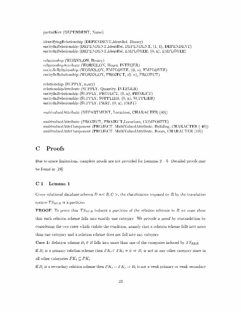
partialKey (DEPENDENT, Name)
identifyingRelationship (DEPENDENT IdentRel, Binary)entityInRelationship (DEPENDENT IdentRel, DEPENDENT, (1, 1), DEPENDENT)entityInRelationship (DEPENDENT IdentRel, EMPLOYEE, (0, n), EMPLOYEE)
relationship (WORKS ON, Binary)relationshipAttribute (WORKS ON, Hours, INTEGER)entityInRelationship (WORKS ON, EMPLOYEE, (0, n), EMPLOYEE)entityInRelationship (WORKS ON, PROJECT, (0, n), PROJECT)
relationship (SUPPLY, n ary)relationshipAttribute (SUPPLY, Quantity, INTEGER)entityInRelationship (SUPPLY, PROJECT, (0, n), PROJECT)entityInRelationship (SUPPLY, SUPPLIER, (0, n), SUPPLIER)entityInRelationship (SUPPLY, PART, (0, n), PART)
multivaluedAttribute (DEPARTMENT, Locations, CHARACTER (40))
multivaluedAttribute (PROJECT, PROJECT Locations, COMPOSITE)multivaluedAttrComponent (PROJECT, MultiValuedAttribute, Building, CHARACTER ( 40))multivaluedAttrComponent (PROJECT, MultiValuedAttribute, Room, CHARACTER (10))
C Proofs
Due to space limitations, complete proofs are not provided for Lemmas 2 { 5. Detailed proofs may
be found in [19].
C.1 Lemma 1
Given relational database schema D =< R;C >, the classi�cation imposed on R by the translation
system TSRER is a partition.
PROOF: To prove that TSRER induces a partition of the relation schemes in R we must show
that each relation scheme falls into exactly one category. We provide a proof by contradiction by
considering the two cases which violate the condition, namely that a relation scheme falls into more
than one category and a relation scheme does not fall into any category.
Case 1: Relation scheme Ri 2 R falls into more than one of the categories induced by TSRER.
If Ri is a primary relation scheme then PKi \ FKi = � ) Ri is not in any other category since in
all other categories FKi � PKi.
If Ri is a secondary relation scheme then PKi = FKi ) Ri is not a weak primary or weak secondary
23
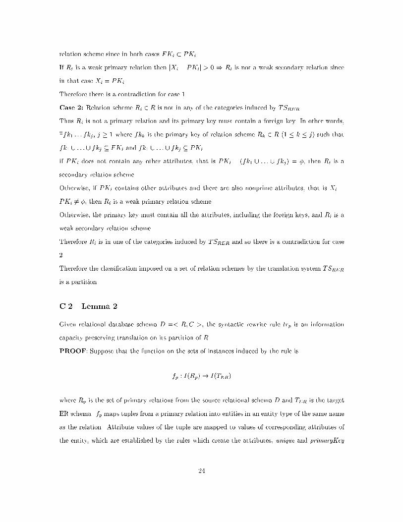
relation scheme since in both cases FKi � PKi.
If Ri is a weak primary relation then jXi � PKij > 0 ) Ri is not a weak secondary relation since
in that case Xi = PKi.
Therefore there is a contradiction for case 1.
Case 2: Relation scheme Ri 2 R is not in any of the categories induced by TSRER.
Thus Ri is not a primary relation and its primary key must contain a foreign key. In other words,
9fk1 : : : fkj , j � 1 where fkk is the primary key of relation scheme Rk 2 R (1 � k � j) such that
fk1 [ : : : [ fkj � FKi and fk1 [ : : : [ fkj � PKi.
if PKi does not contain any other attributes, that is PKi � (fk1 [ : : : [ fkj) = �, then Ri is a
secondary relation scheme.
Otherwise, if PKi contains other attributes and there are also nonprime attributes, that is Xi �
PKi 6= �, then Ri is a weak primary relation scheme.
Otherwise, the primary key must contain all the attributes, including the foreign keys, and Ri is a
weak secondary relation scheme.
Therefore Ri is in one of the categories induced by TSRER and so there is a contradiction for case
2.
Therefore the classi�cation imposed on a set of relation schemes by the translation system TSRER
is a partition.
C.2 Lemma 2
Given relational database schema D =< R;C >, the syntactic rewrite rule trp is an information
capacity preserving translation on its partition of R.
PROOF: Suppose that the function on the sets of instances induced by the rule is
fp : I(Rp)! I(TER)
where Rp is the set of primary relations from the source relational schema D and TER is the target
ER schema. fp maps tuples from a primary relation into entities in an entity type of the same name
as the relation. Attribute values of the tuple are mapped to values of corresponding attributes of
the entity, which are established by the rules which create the attributes, unique and primaryKey
24
constraints on the tuple are re ected as key constraints on the entity and references constraints on
the tuple are represented as relationships involving the entity.
The function fp is total since every tuple in I(Rp) can be mapped to a corresponding entity in
I(TER). It is also an injection since its inverse, f�1p , is guaranteed to map an entity back to its
original source tuple because all attribute values, and constraint information, are maintained by the
mappings. In other words, for all i 2 I(Rp)
i = f�1p � fp(i)
Since the translation rule induces a function on the sets of instances that is both total and
injective, we conclude that the rule is an information capacity preserving translation.
C.3 Lemma 3
Given relational database schema D =< R;C >, the syntactic rewrite rule trwp is an information
capacity preserving translation on its partition of R.
PROOF: Similar argument to the proof of Lemma 2.
C.4 Lemma 4
Given relational database schema D =< R;C >, the syntactic rewrite rule trs is an information
capacity preserving translation on its partition of R.
PROOF: Similar argument to the proof of Lemma 2.
C.5 Lemma 5
Given relational database schema D =< R;C >, the syntactic rewrite rule trws is an information
capacity preserving translation on its partition of R.
PROOF: Similar argument to the proof of Lemma 2.
25