Embed Size (px)
Citation preview
NoS
Commission of the European Communities
Information Bulletin of the Steel Industry Safety and
Health Commission
1984

A publication of the Commission of the European Communities
Prepared by the Directorate-General for Employment, Social Affairs and Education, in collaboration with the Directorate-General for Information Market and Innovation.
Notice
Neither the Commission of the European Communities nor any person acting on its behalf may be held responsible for the use to which the information contained in this publication might be put.
©Commission of the European Communities Reproduction of .the contents of this booklet, in part or in whole, is permitted only with the prior permission of the Editor.
Accidents
1. Lifting operations
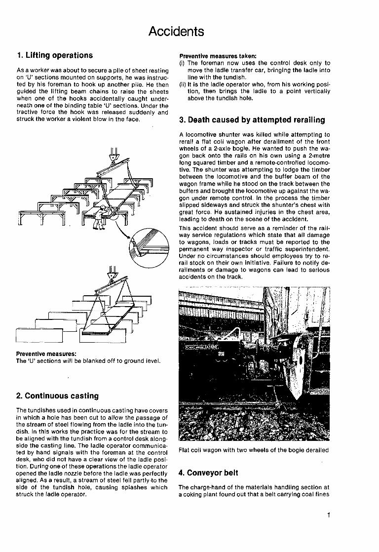
As a worker was about to secure a pile of sheet resting on 'U' sections mounted on supports, he was instructed by his foreman to hook up another pile. He then guided the lifting beam chains to raise the sheets when one of the hooks accidentally caught underneath one of the binding table 'U' sections. Under the tractive force the hook was released suddenly and struck the worker a violent blow in the face.
Preventive measures: The 'U' sections will be blanked off to ground level.
2. Continuous casting
The tundishes used in continuous casting have covers in which a hole has been cut to allow the passage of the stream of steel flowing from the ladle into the tundish. In this works the practice was for the stream to be aligned with the tundish from a control desk alongside the casting line. The ladle operator communicated by hand signals with the foreman at the control desk, who did not have a clear view of the ladle position. During one of these operations the ladle operator opened the ladle nozzle before the ladle was perfectly aligned. As a result, a stream of steel fell partly·to the side of the tundish hole, causing splashes which struck the ladle operator.
Preventive measures taken: (i) The foreman now uses the control desk only to
move the ladle transfer car, bringing the ladle into line with the tundish.
(ii) It is the ladle operator who, from his working position, then brings the ladle to a point vertically above the tundish hole.
3. Death caused by attempted rerailing
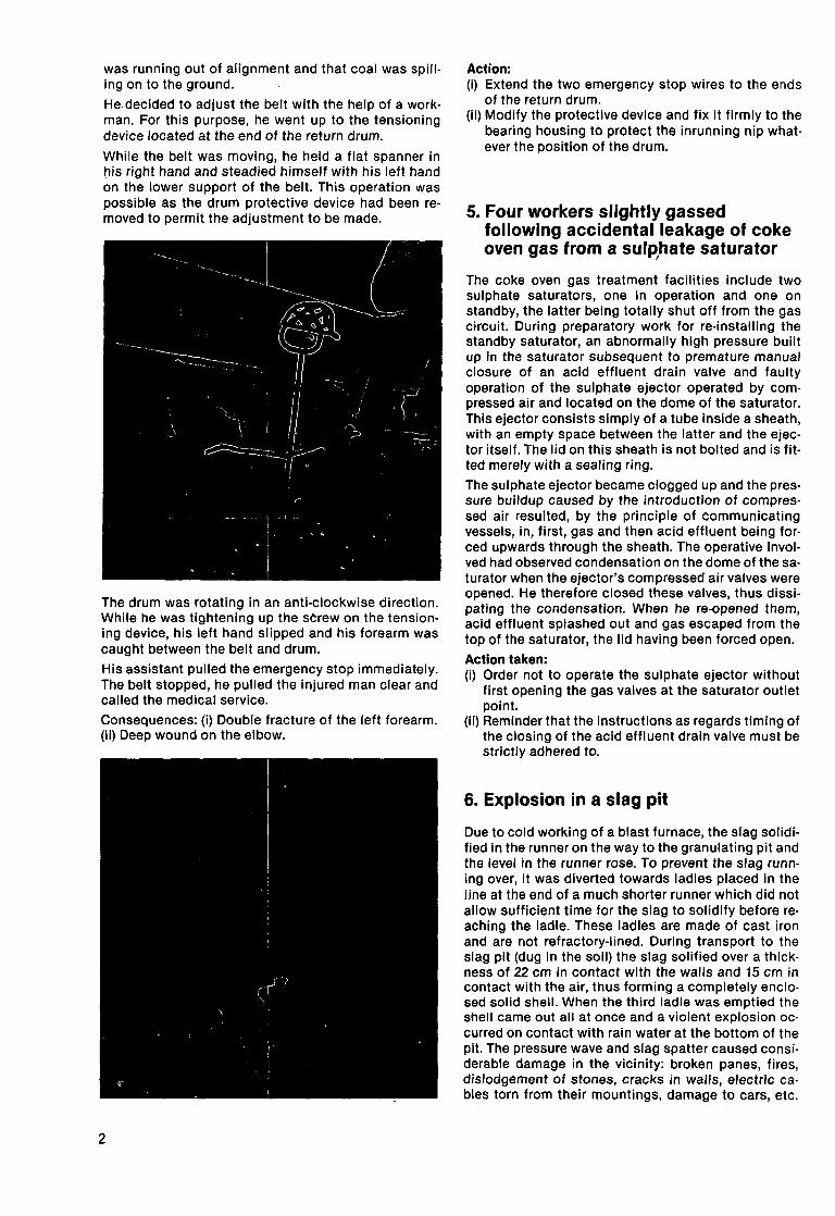
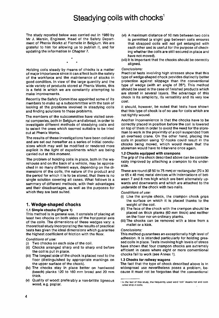
A locomotive shunter was killed while attempting to rerail a flat coil wagon after derailment of the front wheels of a 2-axle bogie. He wanted to push the wagon back onto the rails on his own using a 2-metre long squared timber and a remote-controlled locomotive. The shunter was attempting to lodge the timber between the locomotive and the buffer beam of the wagon frame while he stood on the track between the buffers and brought the locomotive up against the wagon under remote control. In the process the timber slipped sideways and struck the shunter's chest with great force. He sustained injuries in the chest area, leading to death on the scene of the accident.
This accident should serve as a reminder of the railway service regulations which state that all damage to wagons, loads or tracks must be reported to the permanent way inspector or traffic superintendent. Under no circumstances should employees try to rerail stock on their own initiative. Failure to notify derailments or damage to wagons can lead to serious accidents on the track.
Flat coil wagon with two wheels of the bogie derailed
4. Conveyor belt
The charge-hand of the materials handling section at a coking plant found out that a belt carrying coal fines
1
was running out of alignment and that coal was spilling on to the ground.
He.decided to adjust the belt with the help of a workman. For this purpose, he went up to the tensioning device located at the end of the return drum.
While the belt was moving, he held a flat spanner in !:lis right hand and steadied himself with his left hand on the lower support of the belt. This operation was possible as the drum protective device had been removed to permit the adjustment to be made.
The drum was rotating in an anti-clockwise direction. While he was tightening up the screw on the tensioning device, his left hand slipped and his forearm was caught between the belt and drum.
His assistant pulled the emergency stop immediately. The belt stopped, he pulled the injured man clear and called the medical service.
Consequences: (i) Double fracture of the left forearm. (ii) Deep wound on the elbow.
2
Action: (i) Extend the two emergency stop wires to the ends
of the return drum. (ii) Modify the protective device and fix it firmly to the
bearing housing to protect the inrunning nip what· ever the position of the drum.
5. Four workers slightly gassed following accidental leakage of coke oven gas from a suiP,hate saturator
The coke oven gas treatment facilities include two sulphate saturators, one in operation and one on standby, the latter being totally shut off from the gas circuit. During preparatory work for re-installing the standby saturator, an abnormally high pressure built up in the saturator subsequent to premature manual closure of an acid effluent drain valve and faulty operation of the sulphate ejector operated by compressed air and located on the dome of the saturator. This ejector consists simply of a tube inside a sheath, with an empty space between the latter and the ejector itself. The lid on this sheath is not bolted and is fitted merely with a sealing ring.
The sulphate ejector became clogged up and the pressure buildup caused by the introduction of compressed air resulted, by the principle of communicating vessels, in, first, gas and then acid effluent being forced upwards through the sheath. The operative involved had observed condensation on the dome of the saturator when the ejector's compressed air valves were opened. He therefore closed these valves, thus dissipating the condensation. When he re-opened them, acid effluent splashed out and gas escaped from the top of the saturator, the lid having been forced open.
Action taken: (i) Order not to operate the sulphate ejector without
first opening the gas valves at the saturator outlet point.
(ii) Reminder that the instructions as regards timing of the closing of the acid effluent drain valve must be strictly adhered to.
6. Explosion in a slag pit
Due to cold working of a blast furnace, the slag solidified in the runner on the way to the granulating pit and the level in the runner rose. To prevent the slag running over, it was diverted towards ladles placed in the line at the end of a much shorter runner which did not allow sufficient time for the slag to solidify before reaching the ladle. These ladles are made of cast iron and are not refractory-lined. During transport to the slag pit (dug in the soil) the slag salified over a thickness of 22 em in contact with the walls and 15 em in contact with the air, thus forming a completely enclosed solid shell. When the third ladle was emptied the shell came out all at once and a violent explosion occurred on contact with rain water at the bottom of the pit. The pressure wave and slag spatter caused considerable damage in the vicinity: broken panes, fires, dislodgement of stones, cracks in walls, electric cables torn from their mountings, damage to cars, etc.
(253 cases of damage in a radius of 400 metres around the site of the explosion.)
The hypothesis that the water broke down into oxygen and hydrogen and that the resulting hydrogen subsequently exploded is not confirmed by the analyses carried out at the inquiry.
The pressure built up in the shell by the vapour from the rainwater superheated by the slag was sufficient to account for the damage. The impact on emptying, uneven ground and the relative malleability of the slag crust which had solidified on top of the ladle, caused the crust to crack allowing a small quantity of rainwater to penetrate the shell. This water was vaporized inside the shell and caused a rapid increase in pressure. This, combined with the cooling effect of the water around the shell, caused the cracks to close. The wa· ter vapour was thus enclosed and such a high pressure built up that the shell finally exploded.
Measures taken: (i) An additional catch sump in the pit with an auto
matic rainwater draining system was to be built. (ii) A decision was taken to ensure that slag is always
poured on to a slope or a bank and not into the bottom of the pit directly.
(iii) More protection for operatives such as walls, win· dow gratings and roofing was to be provided.
314
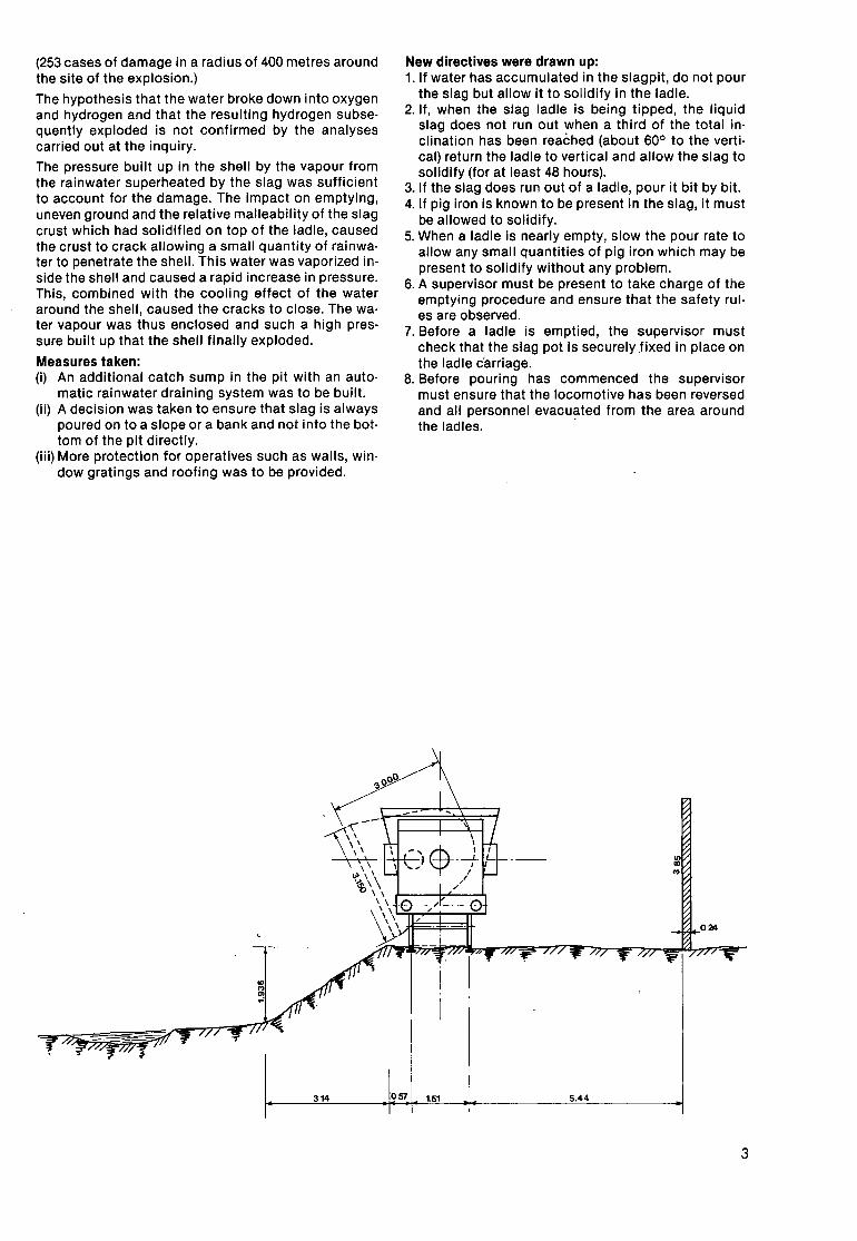
New directives were drawn up: 1.1f water has accumulated in the slagpit, do not pour
the slag but allow it to solidify in the ladle. 2. If, when the slag ladle is being tipped, the liquid
slag does not run out when a third of the total in· clination has been reached (about 60° to the verti· cal) return the ladle to vertical and allow the slag to solidify (for at least 48 hours).
3. If the slag does run out of a ladle, pour it bit by bit. 4. If pig iron is known to be present in the slag, it must
be allowed to solidify. 5. When a ladle is nearly empty, slow the pour rate to
allow any small quantities of pig iron which may be present to solidify without any problem.
6. A supervisor must be present to take charge of the emptying procedure and ensure that the safety rul· es are observed.
7. Before a ladle is emptied, the supervisor must check that the slag pot is securely .fixed in place on the ladle c'arriage.
8. Before pouring has commenced the supervisor must ensure that the locomotive has been reversed and all personnel evacu~ted from the area around the ladles.
057 1.51 5.44
3
Steadying coils with chocks1
The study reported below was carried out in 1980 by Mr J. Marsin, Engineer, Head of the Safety Depart· ment of Phenix Works at Flemelle in Belgium. We are grateful to him for allowing us to publish it, and for updating the information in Chapter 7.
•
Holding coils steady by means of chocks is a matter of major importance since it can affect both the safety of the workforce and the maintenance of stocks in good condition. In view of the large quantity and the wide variety of products stored at Phenix Works, this is a field in which we are constantly attempting to make improvements.
Recently the Safety Committee appointed some of its members to make up a subcommittee with the task of looking at the problems involved in steadying coils and finding solutions to these problems.
The members of the subcommittee have visited seve· ral companies, both in Belgium and abroad, in order to investigate different methods of steadying coils and to select the ones which seemed suitable to be tried out at Phenix Works.
The results of these investigations have been collated and are set out hereafter as a series of initial conclu· sions which may well be modified or rendered more explicit in the light of experiments which are being carried out at this moment.
The problem of holding coils in place, both in the warehouse and on the back of a vehicle, may be approached in so many different ways, depending on the di· mansions of the coils, the nature of the product and the period for which it is to be stored, that there is no single solution covering all cases. What follows is a summary of different methods, with their advantages and their disadvantages, as well as the purposes for which they are best suited.
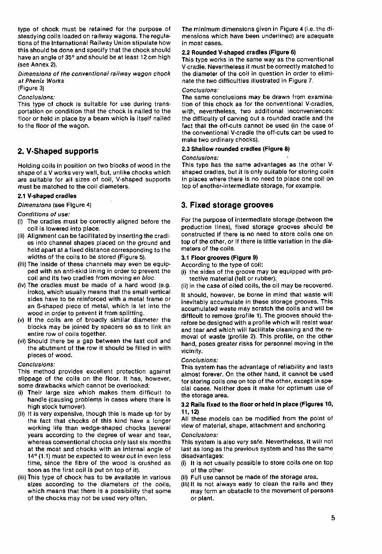
1. Wedge-shaped chocks 1.1 Simple chocks (Figure 1) This method is in general use. It consists of placing at least two chocks on both sides of the horizontal axis of the coils. The dimensions of these wedges vary: a theoretical study incorporating the results of practical tests has given the ideal dimensions which guarantee the highest coefficient of friction with the floor.
Conditions of use: (i) Two chocks on each side of the coil. (ii) Chocks arranged sharp end to sharp end before
the coil is put in place. (iii) The longest side of the chock is placed next to the
floor (distinguished by appropriate markings on the upper surface of the chock).
(iv) The chocks stay in place better on hardwood (beech) planks 120 to 160 mm broad and 20 mm thick.
(v) Quality of wood: preferably a non·brittle ligneous wood, e.g. poplar.
4
(vi) A maximum distance of 10 mm between two coils is permitted (a slight gap between coils ensures that strapped coils will not get entangled with each other and is useful for the purpose of check· ing whether the coils are still secured in place and have not moved) .
(vii) It is important that the chocks should be correctly aligned.
Conclusions: Practical tests involving high stresses show that this type of wedge-shaped chock provides distinctly better protection against slippage than the conventional type of wedge (with an angle of 35°). This method should be used in the case of finished products which are stored in several layers. The advantage of this chock is its simplicity, its versatility and its very low cost.
It should, however, be noted that tests have shown that this type of chock is of no use for coils which are not tightly wound. Another inconvenience is that the chocks have to be correctly placed in position before the coil is lowered on top of them in order to avoid the need for the storeman to work in the proximity of a coil suspended from an overhead crane. On the other hand, placing the coils in position using 'C'-hooks could result in the chocks being moved, which would mean that the storeman would have to intervene once again.
1.2 Chocks equipped with crampons The grip of the chock described above can be considerably improved by attaching a crampon to its underside.
These are round (0 50 to 75 mm) or rectangular (70 x 30 or 65 x 48 mm) metal devices with indentations of between 7 and 8 mm high which are bent alternately upwards and downwards and which are attached to the underside of the chock with two nails.
Conditions of use: (i) Like the simple chock, the crampon chock grips
the surface on which it is placed thanks to the weight of the coil.
(ii) The face of the chock with the crampon should be placed on thick planks (60 mm thick) and neither on the floor nor on ordinary planks.
(iii) The chocks can be removed with a blow from a mallet or a kick.
Conclusions: This method guarantees an exceptionally high level of adhesion. It is intended particularly for holding greased coils in place. Tests involving high levels of stress have shown that four crampon chocks are extremely efficient in cases where eight or more conventional chocks fail to work (see Annex 1).
1.3 Chocks for railway wagons The fact that the type of chock described above is in widespread use nevertheless poses a problem, be· cause it must not be forgotten that the conventional
' In the text of this study, the frequently used word 'coil' means hot and cold· rolled stnp on coils.
type of chock must be retained for the purpose of steadying coils loaded on railway wagons. The regulations of the International Railway Union stipulate how this should be done and specify that the chock should have an angle of 35° and should be at least 12 em high (see Annex 2).
Dimensions of the conventional railway wagon chock at Phenix Works (Figure 3)
Conclusions: This type of chock is suitable for use during trans· portation on condition that the chock is nailed to the floor or held in place by a beam which is itself nailed to the floor of the wagon.
2. V·Shaped supports
Holding coils in position on two blocks of wood in the shape of a V works very well, but, unlike chocks which are suitable for all sizes of coil, V-shaped supports must be matched to the coil diameters.
2.1 V-shaped cradles
Dimensions (see Figure 4)
Conditions of use: (i) The cradles must be correctly aligned before the
coil is lowered into place. (ii) Alignment can be facilitated by inserting the cradl
es into channel shapes placed on the ground and held apart at a fixed distance corresponding to the widths of the coils to be stored (Figure 5).
(iii) The inside of these channels may even be equipped with an anti-skid lining in order to prevent the coil and its two cradles from moving en bloc.
(iv) The cradles must be made of a hard wood (e.g. iroko), which usually means that the small vertical sides have to be reinforced with a metal frame or an S-shaped piece of metal, which is let into the wood in order to prevent it from splitting.
(v) If the coils are of broadly similar diameter the blocks may be joined by spacers so as to link an entire row of coils together.
(vi) Should there be a gap between the last coil and the abutment of the row it should be filled in with pieces of wood.
Conclusions: This method provides excellent protection against slippage of the coils on the floor. It has, however, some drawbacks which cannot be overlooked: (i) Their large size which makes them difficult to
handle (causing problern.s in cases where there is high stock turnover).
(ii) It is very expensive, though this is made up for by the fact that chocks of this kind have a longer working life than wedge-shaped chocks (several years according to the degree of wear and tear, whereas conventional chocks only last six months at the most and chocks with an internal angle of 14 ° (1.1) must be expected to wear out in even less time, since the fibre of the wood is crushed as soon as the first coil is put on top of it).
(iii) This type of chock has to be available in various sizes according to the diameters of the coils, which means that there is a possibility that some of the chocks may not be used very often.
The minimum dimensions given in Figure 4 (i.e. the di· mansions which have been underlined) are adequate in most cases.
2.2 Rounded V-shaped cradles (Figure 6) This type works in the same way as the conventional V-cradle. Nevertheless it must be correctly matched to the diameter of the coil in question in order to eliminate the two difficulties illustrated in Figure 7.
Conclusions: The same conclusions may be drawn from examina· tion of this chock as for the conventional V-cradles, with, nevertheless, two additional inconveniences: the difficulty of carving out a rounded cradle and the fact that the off-cuts cannot be used (in the case of the conventional V-cradle the off-cuts can be used to make two ordinary chocks).
2.3 Shallow rounded cradles (Figure 8)
Conclusions: This type has the same advantages as the other V· shaped cradles, but it is only suitable for storing coils in places where there is no need to place one coil on top of another-intermediate storage, for example.
3. Fixed storage grooves
For the purpose of intermediate storage (between the production lines), fixed storage grooves should be constructed if there is no need to store coils one on top of the other, or if there is little variation in the diameters of the coils.
3.1 Floor grooves (Figure 9) According to the type of coil: (i) the sides of the groove may be equipped with pro-
tective material (felt or rubber); (ii) in the case of oiled coils, the oil may be recovered.
It should, however, be borne in mind that waste will inevitably accumulate in these storage grooves. This accumulated waste may scratch the coils and will be difficult to remove (profile 1). The grooves should therefore be designed with a profile which will resist wear and tear and which will facilitate cleaning and the removal of waste (profile 2). This profile, on the other hand, poses greater risks for personnel moving in the vicinity.
Conclusions: This system has the advantage of reliability and lasts almost forever. On the other hand, it cannot be used for storing coils one on top of the other, except in spe· cial cases. Neither does it make for optimum use of the storage area.
3.2 Rails fixed to the floor or held in place (Figures 10, 11' 12) All these models can be modified from the point of view of material, shape, attachment and anchoring.
Conclusions: This system is also very safe. Nevertheless, it will not last as long as the previous system and has the same disadvantages: (i) It is not usually possible to store coils one on top
of the other. (ii) Full use cannot be made of the storage area. (iii) It is not always easy to clean the rails and they
may form an obstacle to the movement of persons or plant.
5
Fig. 1
Fig. 4
Fig. 7
Oil recovery pit
Fig. 10
Fig. 14
6
0 1.0 C\1 0 1.0
Underside
Fig. 2
Fig. 5
Fig. 8
Fig. 11
Fig. 12
Fig. 3
Fig. 6
Heavy plate
Fig. 9
Fig. 13
Fig. 16
:iS C\1 0 0 N
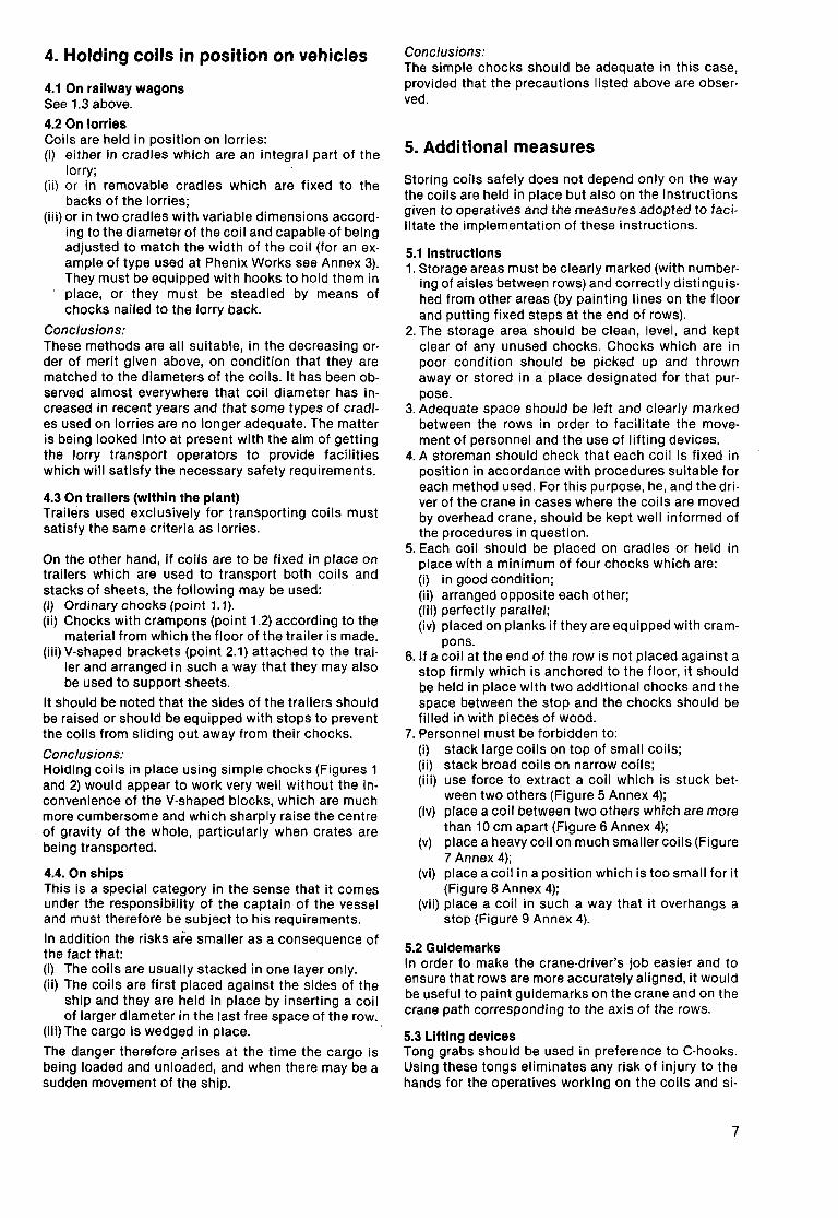
4. Holding coils in position on vehicles
4.1 On railway wagons See 1.3 above.
4.2 On lorries Coils are held in position on lorries: (i) either in cradles which are an integral part of the
lorry; (ii) or in removable cradles which are fixed to the
backs of the lorries; (iii) or in two cradles with variable dimensions accord
ing to the diameter of the coil and capable of being adjusted to match the width of the coil (for an example of type used at Phenix Works see Annex 3). They must be equipped with hooks to hold them in place, or they must be steadied by means of chocks nailed to the lorry back.
Conclusions: These methods are all suitable, in the decreasing order of merit given above, on condition that they are matched to the diameters of the coils. It has been observed almost everywhere that coil diameter has increased in recent years and that some types of cradles used on lorries are no longer adequate. The matter is being looked into at present with the aim of getting the lorry transport operators to provide facilities which will satisfy the necessary safety requirements.
4.3 On trailers (within the plant) Trailers used exclusively for transporting coils must satisfy the same criteria as lorries.
On the other hand, if coils are to be fixed in place on trailers which are used to transport both coils and stacks of sheets, the following may be used: (i) Ordinary chocks (point 1.1 ). (ii) Chocks with crampons (point 1.2) according to the
material from which the floor of the trailer is made. (iii) V-shaped brackets (point 2.1) attached to the trai
ler and arranged in such a way that they may also be used to support sheets.
It should be noted that the sides of the trailers should be raised or should be equipped with stops to prevent the coils from sliding out away from their chocks.
Conclusions: Holding coils in place using simple chocks (Figures 1 and 2) would appear to work very well without the inconvenience of the V-shaped blocks, which are much more cumbersome and which sharply raise the centre of gravity of the whole, particularly when crates are being transported.
4.4. On ships This is a special category in the sense that it comes under the responsibility of the captain of the vessel and must therefore be subject to his requirements.
In addition the risks are smaller as a consequence of the fact that: (i) The coils are usually stacked in one layer only. (ii) The coils are first placed against the sides of the
ship and they are held in place by inserting a coil of larger diameter in the last free space of the row.
(iii) The cargo is wedged in place. ·
The danger therefore .arises at the time the cargo is being loaded and unloaded, and when there may be a sudden movement of the ship.
Conclusions: The simple chocks should be adequate in this case, provided that the precautions listed above are observed.
5. Additional measures
Storing coils safely does not depend only on the way the coils are held in place but also on the instructions given to operatives and the measures adopted to facilitate the implementation of these instructions.
5.1 Instructions 1. Storage areas must be clearly marked (with number
ing of aisles between rows) and correctly distinguished from other areas (by painting lines on the floor and putting fixed steps at the end of rows).
2. The storage area should be clean, level, and kept clear of any unused chocks. Chocks which are in poor condition should be picked up and thrown away or stored in a place designated for that purpose.
3. Adequate space should be left and clearly marked between the rows in order to facilitate the movement of personnel and the use of lifting devices.
4. A storeman should check that each coil is fixed in position in accordance with procedures suitable for each method used. For this purpose, he, and the driver of the crane in cases where the coils are moved by overhead crane, should be kept well informed of the procedures in question.
5. Each coil should be placed on cradles or held in place with a minimum of tour chocks which are: (i) in good condition; (ii) arranged opposite each other; (iii) perfectly parallel; (iv) placed on planks if they are equipped with cram
pons. 6. It a coil at the end of the row is not placed against a
stop firmly which is anchored to the floor, it should be held in place with two additional chocks and the space between the stop and the chocks should be filled in with pieces of wood.
7. Personnel must be forbidden to: (i) stack large coils on top of small coils; (ii) stack broad coils on narrow coils; (iii) use force to extract a coil which is stuck bet
ween two others (Figure 5 Annex 4); (iv) place a coil between two others which are more
than 10 em apart (Figure 6 Annex 4); (v) place a heavy coil on much smaller coils (Figure
7 Annex 4); (vi) place a coil in a position which is too small for it
(Figure 8 Annex 4); (vii) place a coil in such a way that it overhangs a
stop (Figure 9 Annex 4).
5.2 Guidemarks In order to make the crane-driver's job easier and to ensure that rows are more accurately aligned, it would be useful to paint guidemarks on the crane and on the crane path corresponding to the axis of the rows.
5.3 Lifting devices Tong grabs should be used in preference to C-hooks. Using these tongs eliminates any risk of injury to the hands for the operatives working on the coils and si-
7
milarly prevents blows to the coils. Electro·mechani· cally controlled tongs perform better than hydraulic ones.
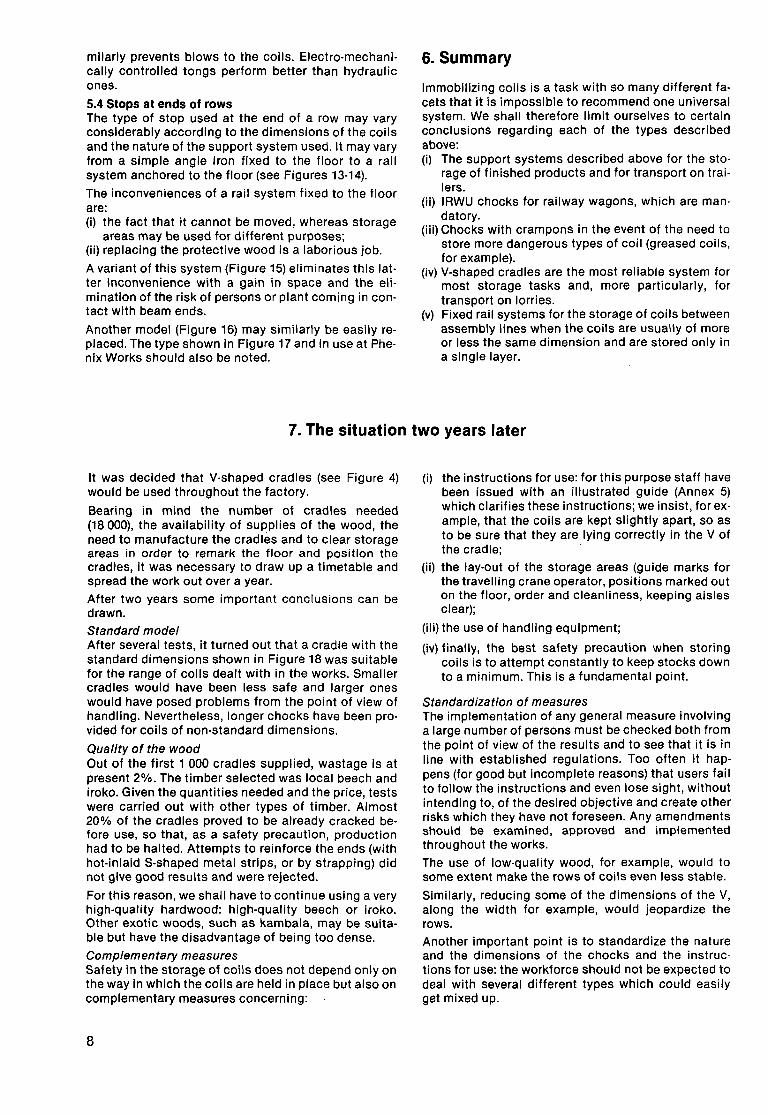
5.4 Stops at ends of rows The type of stop used at the end of a row may vary considerably according to the dimensions of the coils and the nature of the support system used. It may vary from a simple angle iron fixed to the floor to a rail system anchored to the floor (see Figures 13-14).
The inconveniences of a rail system fixed to the floor are: (i) the fact that it cannot be moved, whereas storage
areas may be used for different purposes; (ii) replacing the protective wood is a laborious job.
A variant of this system (Figure 15) eliminates this latter inconvenience with a gain in space and the elimination of the risk of persons or plant coming in contact with beam ends.
Another model (Figure 16) may similarly be easily replaced. The type shown in Figure 17 and in use at Phenix Works should also be noted.
6. Summary
Immobilizing coils is a task with so many different facets that it is impossible to recommend one universal system. We shall therefore limit ourselves to certain conclusions regarding each of the types described above: (i) The support systems described above for the sto·
rage of finished products and for transport on trai· lers.
(ii) IRWU chocks for railway wagons, which are man· datory.
(iii) Chocks with crampons in the event of the need to store more dangerous types of coil (greased coils, for example).
(iv) V-shaped cradles are the most reliable system for most storage tasks and, more particularly, for transport on lorries.
(v) Fixed rail systems for the storage of coils between assembly lines when the coils are usually of more or less the same dimension and are stored only in a single layer.
7. The situation two years later
It was decided that V-shaped cradles (see Figure 4) would be used throughout the factory.
Bearing in mind the number of cradles needed (18 000), the availability of supplies of the wood, the need to manufacture the cradles and to clear storage areas in order to remark the floor and position the cradles, it was necessary to draw up a timetable and spread the work out over a year.
After two years some important conclusions can be drawn.
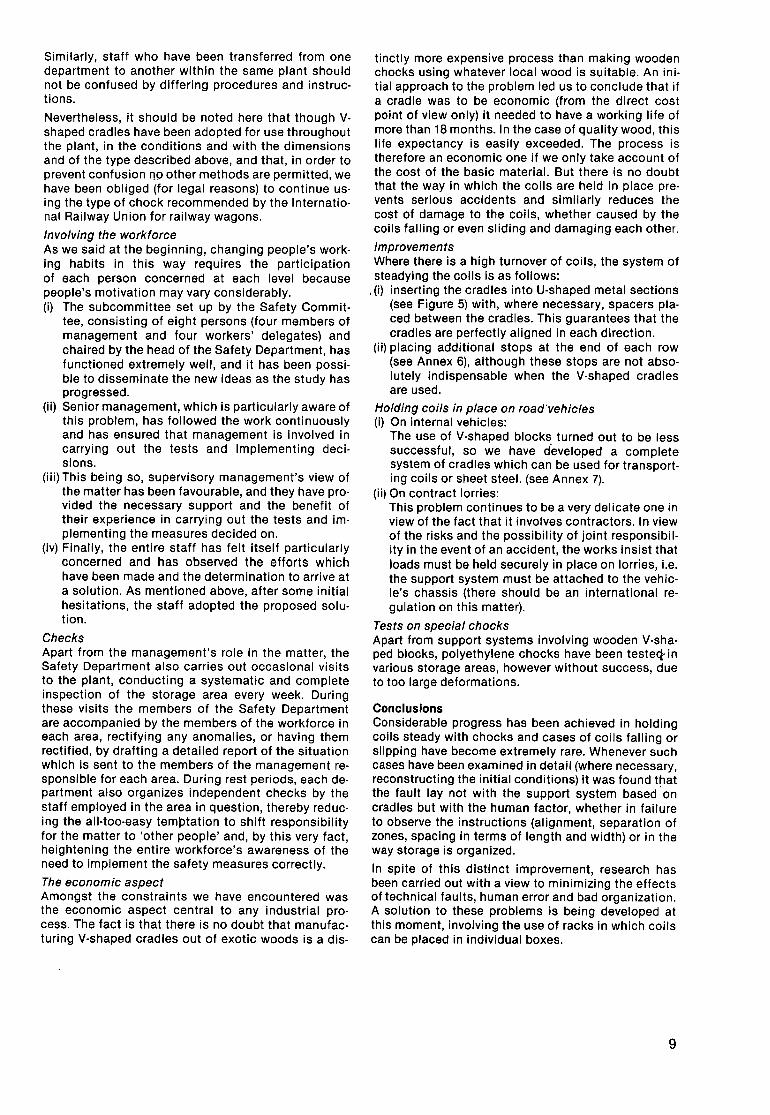
Standard model After several tests, it turned out that a cradle with the standard dimensions shown in Figure 18 was suitable for the range of coils dealt with in the works. Smaller cradles would have been less safe and larger ones would have posed problems from the point of view of handling. Nevertheless, longer chocks have been provided for coils of non-standard dimensions.
Quality of the wood Out of the first 1 000 cradles supplied, wastage is at present 2%. The timber selected was local beech and iroko. Given the quantities needed and the price, tests were carried out with other types of timber. Almost 20% of the cradles proved to be already cracked before use, so that, as a safety precaution, production had to be halted. Attempts to reinforce the ends (with hot-inlaid S-shaped metal strips, or by strapping) did not give good results and were rejected.
For this reason, we shall have to continue using a very high-quality hardwood: high-quality beech or iroko. Other exotic woods, such as kambala, may be suitable but have the disadvantage of being too dense.
Complementary measures Safety in the storage of coils does not depend only on the way in which the coils are held in place but also on complementary measures concerning:
8
(i) the instructions for use: for this purpose staff have been issued with an illustrated guide (Annex 5) which clarifies these instructions; we insist, for example, that the coils are kept slightly apart, so as to be sure that they are lying correctly in the V of the cradle;
(ii) the lay-out of the storage areas (guide marks for the travelling crane operator, positions marked out on the floor, order and cleanliness, keeping aisles clear);
(iii) the use of handling equipment;
(iv) finally, the best safety precaution when storing coils is to attempt constantly to keep stocks down to a minimum. This is a fundamental point.
Standardization of measures The implementation of any general measure involving a large number of persons must be checked both from the point of view of the results and to see that it is in line with established regulations. Too often it happens (for good but incomplete reasons) that users fail to follow the instructions and even lose sight, without intending to, of the desired objective and create other risks which they have not foreseen. Any amendments should be examined, approved and implemented throughout the works. The use of low-quality wood, for example, would to some extent make the rows of coils even less stable.
Similarly, reducing some of the dimensions of the V, along the width for example, would jeopardize the rows.
Another important point is to standardize the nature and the dimensions of the chocks and the instructions for use: the workforce should not be expected to deal with several different types which could easily get mixed up.
Similarly, staff who have been transferred from one department to another within the same plant should not be contused by differing procedures and instructions.
Nevertheless, it should be noted here that though V· shaped cradles have been adopted tor use throughout the plant, in the conditions and with the dimensions and of the type described above, and that, in order to prevent contusion 119 other methods are permitted, we have been obliged (for legal reasons) to continue us· ing the type of chock recommended by the International Railway Union tor railway wagons.
Involving the workforce As we said at the beginning, changing people's working habits in this way requires the participation of each person concerned at each level because people's motivation may vary considerably. (i) The subcommittee set up by the Safety Commit
tee, consisting of eight persons (four members of management and four workers' delegates) and chaired by the head of the Safety Department, has functioned extremely well, and it has been possible to disseminate the new ideas as the study has progressed.
(ii) Senior management, which is particularly aware of this problem, has followed the work continuously and has ensured that management is involved in carrying out the tests and implementing deci· sions.
(iii) This being so, supervisory management's view of the matter has been favourable, and they have pro· vided the necessary support and the benefit of their experience in carrying out the tests and im· plementing the measures decided on.
(iv) Finally, the entire staff has felt itself particularly concerned and has observed the efforts which have been made and the determination to arrive at a solution. As mentioned above, after some initial hesitations, the staff adopted the proposed solution.
Checks Apart from the management's role in the matter, the Safety Department also carries out occasional visits to the plant, conducting a systematic and complete inspection of the storage area every week. During these visits the members of the Safety Department are accompanied by the members of the workforce in each area, rectifying any anomalies, or having them rectified, by drafting a detailed report of the situation which is sent to the members of the management responsible for each area. During rest periods, each de· partment also organizes independent checks by the staff employed in the area in question, thereby reduc· ing the all-too-easy temptation to shift responsibility for the matter to 'other people' and, by this very fact, heightening the entire workforce's awareness of the need to implement the safety measures correctly.
The economic aspect Amongst the constraints we have encountered was the economic aspect central to any industrial pro· cess. The fact is that there is no doubt that manufac· turing V-shaped cradles out of exotic woods is a dis-
tinctly more expensive process than making wooden chocks using whatever local wood is suitable. An ini· tial approach to the problem led us to conclude that if a cradle was to be economic (from the direct cost point of view only) it needed to have a working life of more than 18 months. In the case of quality wood, this life expectancy is easily exceeded. The process is therefore an economic one if we only take account of the cost of the basic material. But there is no doubt that the way in which the coils are held in place pre· vents serious accidents and similarly reduces the cost of damage to the coils, whether caused by the coils falling or even sliding and damaging each other.
Improvements Where there is a high turnover of coils, the system of steadying the coils is as follows:
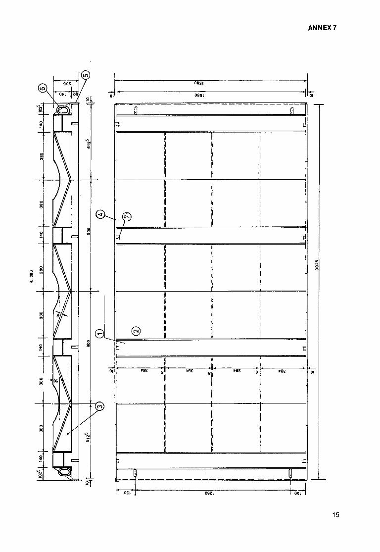
, (i) inserting the cradles into U-shaped metal sections (see Figure 5) with, where necessary, spacers pia· ced between the cradles. This guarantees that the cradles are perfectly aligned in each direction.
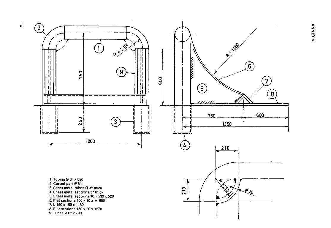
(ii) placing additional stops at the end of each row (see Annex 6), although these stops are not absolutely indispensable when the V-shaped cradles are used.
Holding coils in place on road'vehicles (i) On internal vehicles:
The use of V-shaped blocks turned out to be less successful, so we have developed a complete system of cradles which can be used for transporting coils or sheet steel. (see Annex 7).
(ii) On contract lorries: This problem continues to be a very delicate one in view of the fact that it involves contractors. In view of the risks and the possibility of joint responsibil· ity in the event of an accident, the works insist that loads must be held securely in place on lorries, i.e. the support system must be attached to the vehicle's chassis (there should be an international regulation on this matter).
Tests on special chocks Apart from support systems involving wooden V-shaped blocks, polyethylene chocks have been testeq· in various storage areas, however without success, due to too large deformations.
Conclusions Considerable progress has been achieved in holding coils steady with chocks and cases of coils falling or slipping have become extremely rare. Whenever such cases have been examined in detail (where necessary, reconstructing the initial conditions) it was found that the fault lay not with the support system based· on cradles but with the human factor, whether in failure to observe the instructions (alignment, separation of zones, spacing in terms of length and width) or in the way storage is organized.
In spite of this distinct improvement, research has been carried out with a view to minimizing the effects of technical faults, human error and bad organization. A solution to these problems is being developed at this moment, involving the use of racks in which coils can be placed in individual boxes.
9
ANNEX 1: TEST RELATIONSHIP
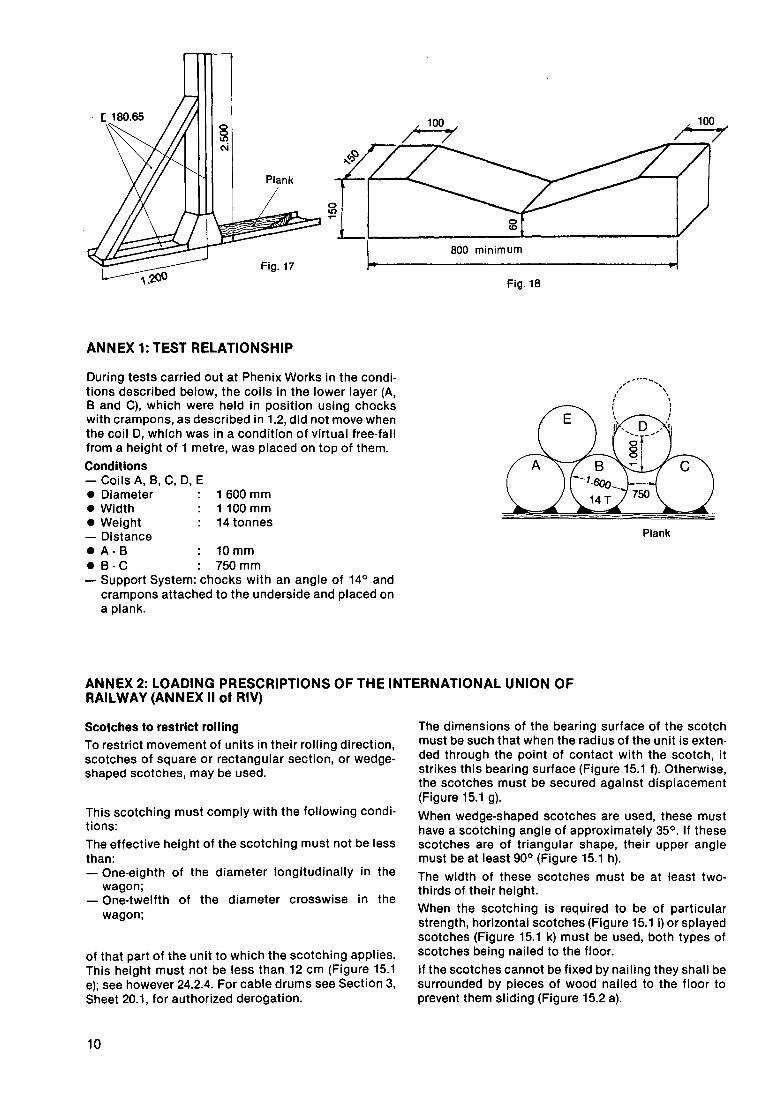
During tests carried out at Phenix Works in the conditions described below, the coils in the lower layer (A, B and C), which were held in position using chocks with crampons, as described in 1.2, did not move when the coil D, which was in a condition of virtual free-fall from a height of 1 metre, was placed on top of them.
Conditions -Coils A, B, C, D, E • Diameter 1 600 mm • Width 1100 mm • Weight 14 tonnes -Distance • A- B 10 mm • B-C 750mm -Support System: chocks with an angle of 14° and
crampons attached to the underside and placed on a plank.
BOO minimum
Fig.18
Plank
ANNEX 2: LOADING PRESCRIPTIONS OF THE INTERNATIONAL UNION OF RAILWAY (ANNEX II of RIV)
Scotches to restrict rolling
To restrict movement of units in their rolling direction, scotches of square or rectangular section, or wedgeshaped scotches, may be used.
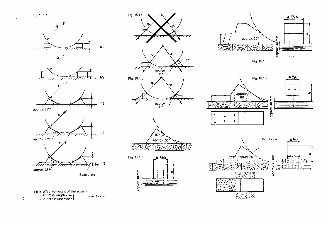
This scotching must comply with the following conditions: The effective height of the scotching must not be less than: - One-eighth of the diameter longitudinally in the
wagon; - One-twelfth of the diameter crosswise in the
wagon;
of that part of the unit to which the scotching applies. This height must not be less than 12 em (Figure 15.1 e); see however 24.2.4. For cable drums see Section 3, Sheet 20.1, for authorized derogation.
10
The dimensions of the bearing surface of the scotch must be such that when the radius of the unit is extended through the point of contact with the scotch, it strikes this bearing surface (Figure 15.1 f). Otherwise, the scotches must be secured against displacement (Figure 15.1 g).
When wedge-shaped scotches are used, these must have a scotching angle of approximately 35°. If these scotches are of triangular shape, their upper angle must be at least 90° (Figure 15.1 h).
The width of these scotches must be at least twothirds of their height.
When the scotching is required to be of particular strength, horizontal scotches (Figure 15.1 i) or splayed scotches (Figure 15.1 k) must be used, both types of scotches being nailed to the floor.
If the scotches cannot be fixed by nailing they shall be surrounded by pieces of wood nailed to the floor to prevent them sliding (Figure 15.2 a).
......
......
Fig. 15.1 e
~
h')
ll!/
,~_<, h')
appro~. 35o/
h')
h')
h')
Base plate
1 h = effective height of the scotch = ~ 1/8 01engthwise} mm. 12 em = ~ 1/12 0 crosswise
Fig. 15.1 h
E E ~ X 0 a. a. as
;:: %h
Fig.15.1i
Fig. 15.1 k
C =I: I .. I
E E
Fig.152a
;:: %h
~
. __/
~ 2/3h
.z:.
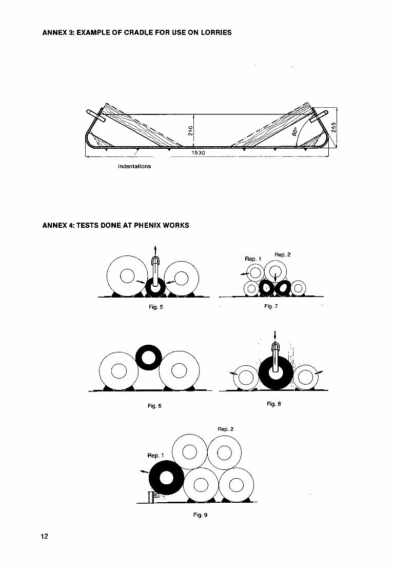
ANNEX 3: EXAMPLE OF CRAD~E FOR USE ON LORRIES
Indentations
ANNEX 4: TESTS DONE AT PHENIX WORKS
Rep. 2
a Fig. 5 Fig. 7
Fig. 6 Fig. 8
Rep.2
Fig.9
12
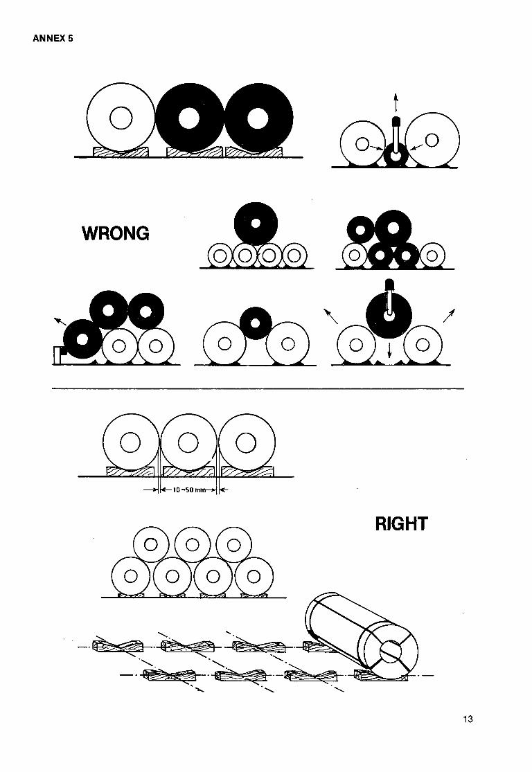
ANNEX 5
WRONG
RIGHT
13
......
.1:>.
I IJ II q II ,, II ,,
0 Ln £"-..
I i 11 II II h II j' tl
11 · 11 ~ 11 II llt II N 0-----111 II l.'o _ --di I
11
tl . ,,
lh-t J' 1000 __ :!!
I
1. Tubing 0 6" x 580 2. Curved part 0 6" 3. Sheet metal tubes 0 3" thick 4. Sheet metal sections 3" thick 5. Sheet metal sections 10 x 530 x 520 6. Flat sections 100 x 10 x ± 650 7. l 150 X 150 X 1150 8. Flat sections 150 x 20 x 1270 9. Tubes 0 6" x 790
0
~
I II II
II ,, II HI II II II I
~-ctJ
I
0 -N
®
f:;;)~f:;;) ,' ~
1350
600
~ z z m X g)
0
"" "'
0
"" "'
0
"" "'
0
"" "'
0
"" "'
0 1:>
"'
01
OBSI
09SI
---------------------------(1
+
e I' II
•B£ I' 811
~Bt
II !I
I, II
:I II
.n~ •at
81:
II
I
II II II II II
I ·I 8
II
li
'I I II
II
•at
~~~--~--------~0~9l~~--------------~~os~
ANNEX 7
01
"' "' 0
"'
15
Bibliography
EUR 9243- Cost of employment injuries, of injuries while travelling between home and place of work, and of occupational diseases in Arbed plants in Belgium, Germany and Luxembourg for 1978-82 period
The first chapter compares the social legislation concerning industrial injuries and occupational diseases in the three countries. It deals with the set of law, the insured risks, the field of application, the allowances, the financing, the risk evaluation and calculation of the employers' contribution.
There is a great difference in the compensation of the annuities for working incapacities. In Luxembourg these annuities are 20% higher than in Germany; in Belgium they are even 25% higher than in Luxembourg.
Let us also point out that in Germany a life annuity is only accorded for working incapacities that are higher than 20%.
The second chapter deals with statistics of industrial injuries, commuter accidents and occupational diseases.
Luxembourg has as many industrial injuries as Germany, but Belgium has only the half of this kind of injuries.
The three countries have about the same number of road accidents.
The number of occupational diseases is the highest in Germany and the lowest in Luxembourg.
The third chapter concerns the cost of accidents which is divided into direct and indirect cost.
The direct cost covers the contribution to the employers' liability insurance and, should this be the case, the payment of lost earnings for accidents.
The indirect cost covers the cost for occupational medicine and first aid, the cost for occupational safety, for ergonomics, for protective clothing and devices, for prevention of the risk of poisoning by carbon monoxide.
The direct cost is the highest in Luxembourg and the lowest in Belgium (nearly the half of the cost in Luxembourg), whereas the indirect cost is the highest in Belgium and the lowest in Germany.
This study is available on microfiche (format NMA - 96 images per microfiche) at a cost of BFR 120 from the Office for Official Publications, 5 rue du Commerce, L-2985 Luxembourg. The secretariat of the Steel Industry Safety and Health Commission has a small number of copies on DIN A4 paper and will send these free, and in the language required (subject to availability of stocks) to adressees in the steel industry only.
16
This periodical is published in English, French, German and ltal1an, and can be obtained free of charge by simply applying to tl"]e Commission of the European Communities, Directorate-General XIII. D1v1sion for Scientific and Technical Communication, L-2920 Luxembourg.
Representatives of the following institutions collaborated in editing this bulletin:
- Associazione industrie siderurgiche italiane Piazza Velasca 8, 1-20122 Milano
- British Steel Corporation 12 Addiscombe Road, Croydon CR9 3JH, England
-Contact Office of Miners' and Metalworkers' Free Trade Unions in the European Communities 58 avenue de Ia Liberte, L-1930 Luxembourg
- Groupement des entreprises siderurgiques et minieres (Gesim) 1 Rue Eugene Schneider, F-57016 Metz
- Groupement des Hauts fourneaux et Acieries belges 47 rue Montoyer, B-1040 Bruxelles
- Wirtschaftsvereinigung Eisen- und Stahlindustrie Breite StraBe 69, D-4000 Dusseldorf 1
They were assisted by officials of the Commission of the European Communities from:
Directorate-General for Employment, Social Affairs and Education; Division: Industrial Safety
Directorate-General for Personnel and Administration; Medium and Long-term Translation Service (Terminology Bureau)
Directorate-General for Information Market and Innovation; Division: Scientific and Technical Communication

OFFICE FOR OFFICIALjPUBLICATIONS OF THE EUROPEAN CqMMUNITIES
L-2985 Luxembourg Catalogue number CD-40-84-723-EN-C