Embed Size (px)
Citation preview

DEDICATED TO THE “WARFIGHTER MEDICTM”
US and ForeignPatents PendingMade in USA
FIELD EXPEDIENT BLEEDING SIMULATION SYSTEMTM
DEDICATED TO THE “WARFIGHTER MEDICTM”
FEBSS HydraSimTM
FEBSS Impact Simulation Trainer (FIST)
TM
Information and Instructions
INTRODUCTION
The HydraSim™ provides the illusion of external hemorrhage at the point of injury. Those that are trained have the opportunity to see and treat bleeding wounds with hemostatic dressings, pressure dressings, and tourniquets just like they would in a real situation. When coupled with the FEBSS Impact Simulation Trainer™ (FIST) the HydraSim™ provides visual bleeding simulation AND the auditory impact simulation associated with the point of wounding during a traumatic event. These simple yet powerful additions increase the realism to any medical training event.
Table of Contents
MultiSim™ Injury Fabrication 1 Upper Extremity Wounds
Lower Extremity Wounds
Getting Started 3 Charge the HydraSim™ Battery
Install the HydraSim™ Battery
Check the HydraSim™ Lines
Preparing the FEBSS™ Refi ll TankMixing Simulation Blood 4 SKEDCO UV Sensitive Simulation Blood (UVSSB)
Simulaids Blood Powder
Filling the HydraSim™
Using the HydraSim™ 7 Live Casualty Simulation
Vomit Simulation
Constructing the Line
Connecting the Line to the HydraSim™
Operating the HydraSim™ during Vomit Simulation
Mannequin Simulation
FEBSS Impact Simulation Trainer (FIST)™ 11 Loading FIST™ Charging Handles
Reloading FIST™ Charging Handles
Connecting the FIST™ Charging handle
Connecting outside the HydraSim™ pack
Connecting inside the HydraSim™ pack
Charging the FIST™
Operating the FIST™
Maintenance Guidelines 15 Battery Maintenance
HydraSim™ Transmitter Battery Maintenance
Monthly Maintenance: Flushing the HydraSim™
Troubleshooting tips 16
Packing List 18
Deluxe Packing List 19
MultiSimTM Injury Fabrication
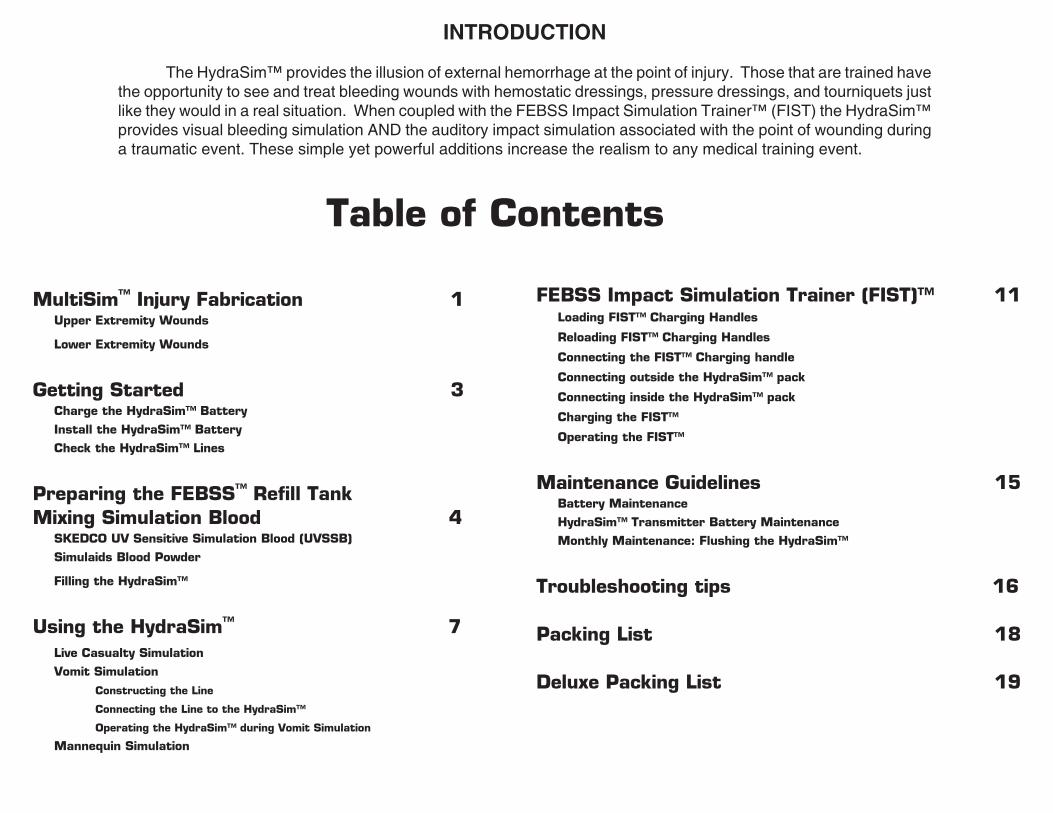
Check the HydraSimTM lines
Unzip the HydraSimTM
side pocket.
Push on each line connector to ensure that each fi tting is fully connected to its corresponding coupler body – lines may have become disconnected during shipment.
Zip up the HydraSimTM side pocket.
Plug in the hot glue gun – consult the instructions for operation contained within the glue gun package.
Upper Extremity Wounds
Cut off an entire leg of the stocking.
Cut fi nger holes into the closed end of the stocking.
Slide an empty water bottle to the desired wound area inside the stocking.
Cut two small tubing holes into the desired wound area of the stocking.
Remove the nasal cannula from its wrapper.
Cut off the nasal fl ares of the nasal cannula.
Slide the two lines through the open end of the stocking, then each line through a tubing hole in the stocking.
Mix enamel paint to desired color on a piece of scrap card-board.
Carefully apply hot glue to the region where the tubing exits the stocking.
MultiSim TM
1
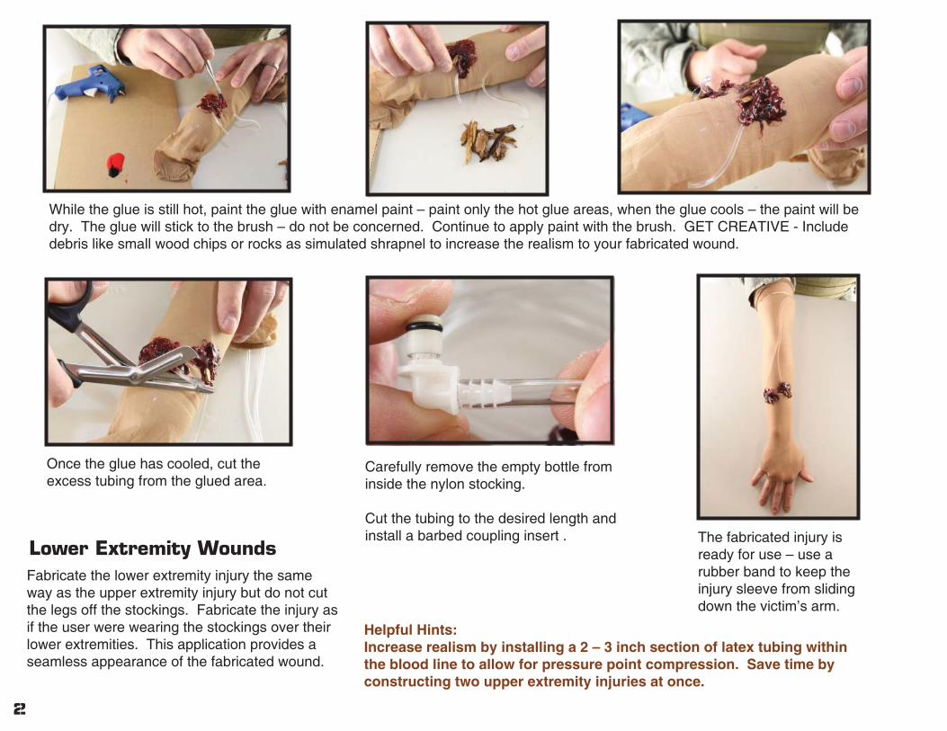
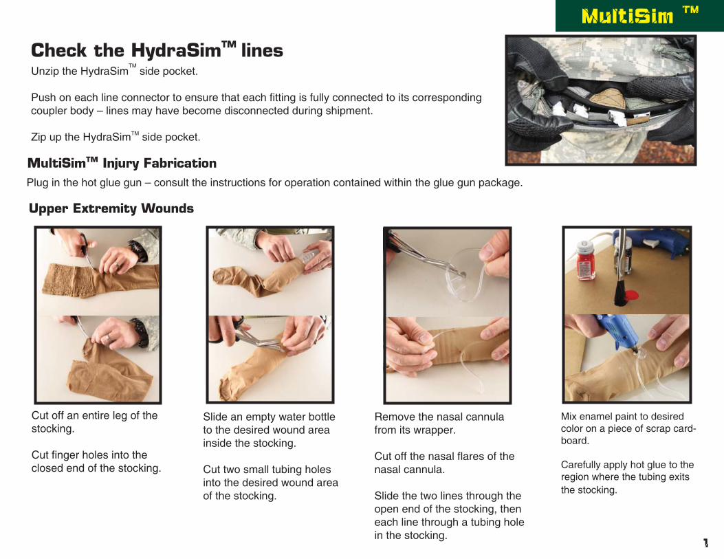
While the glue is still hot, paint the glue with enamel paint – paint only the hot glue areas, when the glue cools – the paint will be dry. The glue will stick to the brush – do not be concerned. Continue to apply paint with the brush. GET CREATIVE - Include debris like small wood chips or rocks as simulated shrapnel to increase the realism to your fabricated wound.
Once the glue has cooled, cut the excess tubing from the glued area.
Carefully remove the empty bottle from inside the nylon stocking.
Cut the tubing to the desired length and install a barbed coupling insert . The fabricated injury is
ready for use – use a rubber band to keep the injury sleeve from sliding down the victim’s arm.
Helpful Hints:Increase realism by installing a 2 – 3 inch section of latex tubing within the blood line to allow for pressure point compression. Save time by constructing two upper extremity injuries at once.
Fabricate the lower extremity injury the same way as the upper extremity injury but do not cut the legs off the stockings. Fabricate the injury as if the user were wearing the stockings over their lower extremities. This application provides a seamless appearance of the fabricated wound.
Lower Extremity Wounds
2
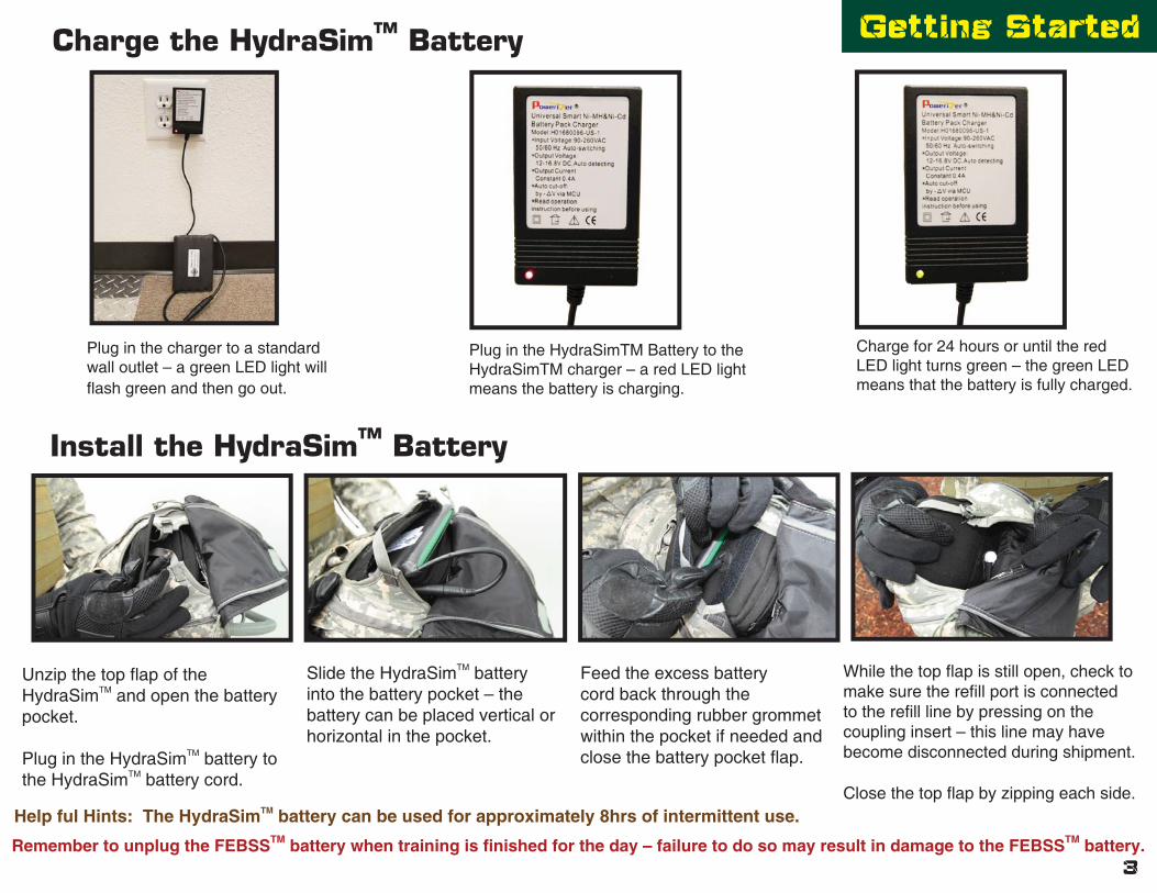
Getting StartedCharge the HydraSimTM Battery
Plug in the charger to a standard wall outlet – a green LED light will fl ash green and then go out.
Plug in the HydraSimTM Battery to the HydraSimTM charger – a red LED light means the battery is charging.
Charge for 24 hours or until the red LED light turns green – the green LED means that the battery is fully charged.
Install the HydraSimTM Battery
Unzip the top fl ap of the HydraSimTM and open the battery pocket.
Plug in the HydraSimTM battery to the HydraSimTM battery cord.
Slide the HydraSimTM battery into the battery pocket – the battery can be placed vertical or horizontal in the pocket.
Feed the excess battery cord back through the corresponding rubber grommet within the pocket if needed and close the battery pocket fl ap.
While the top fl ap is still open, check to make sure the refi ll port is connected to the refi ll line by pressing on the coupling insert – this line may have become disconnected during shipment.
Close the top fl ap by zipping each side.Help ful Hints: The HydraSimTM battery can be used for approximately 8hrs of intermittent use.
Remember to unplug the FEBSSTM battery when training is fi nished for the day – failure to do so may result in damage to the FEBSSTM battery.3
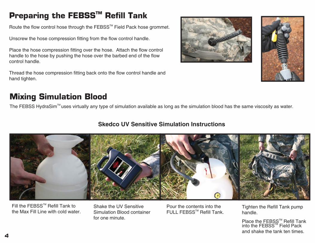
Preparing the FEBSSTM Refi ll TankRoute the fl ow control hose through the FEBSSTM Field Pack hose grommet.
Unscrew the hose compression fi tting from the fl ow control handle.
Place the hose compression fi tting over the hose. Attach the fl ow control handle to the hose by pushing the hose over the barbed end of the fl ow control handle.
Thread the hose compression fi tting back onto the fl ow control handle and hand tighten.
Mixing Simulation BloodThe FEBSS HydraSimTM uses virtually any type of simulation available as long as the simulation blood has the same viscosity as water.
Skedco UV Sensitive Simulation Instructions
Fill the FEBSSTM Refi ll Tank to the Max Fill Line with cold water.
Shake the UV Sensitive Simulation Blood container for one minute.
Pour the contents into the FULL FEBSSTM Refi ll Tank.
Tighten the Refi ll Tank pump handle.
Place the FEBSSTM Refi ll Tank into the FEBSSTM Field Pack and shake the tank ten times.
4

5
Once all simulations are fi nished, wear the garment in the sunlight as long as possible – the red simulation fl uid will turn to a tan color when exposed to direct sunlight and then eventually dry to a white powder. The white powder can then be brushed off of the garment. In some cases the pigment will not completely transform until the garment is almost dry.If a red/pink color still remains due to wrinkling once the garment is dry – soak the garment in water and lay it out in direct sunlight to dry again. Make sure the affected area has no wrinkles that will shade the sunlight. Repeat as needed until red/pink color had faded. Reference the enclosed Material Safety Data Sheet if needed.
Simulaids Blood Powder Instructions
UV Sensitive Simulation Blood Clean up Instructions
Fill FEBSSTM Refi ll Tank to the Max Fill Line with cold water.
Add desired amount of powder – using less of the powder will lighten the color of the simulation blood but it will be easier to wash out of the garment.
Tighten the Refi ll Tank pump handle. Place the FEBSSTM Refi ll Tank into the FEBSSTM Field Pack and close the pack.
Shake the tank side to side to mix the simulation blood.
Helpful Hint: To help in the laundering process, add 1 cup of laundry detergent to the FEBSSTM refi ll tank once the simulation blood is mixed – this may cause irritation if exposed to the eyes or mouth.

Filling the HydraSimTM
Unzip the FEBSS Field Pack and pressurize the Refi ll Tank.
Connect the fl ow control handle to the color coded black coupler body within the HyraSimTM simulated drink tube line.
Once connected, squeeze the yellow fl ow control lever and lock it into place by pushing it forward – simulated blood will fl ow into the HydraSimTM as long as the Refi ll Tank is pressurized and connected to the HydraSimTM Fill Line.
The HydraSimTM will expand with fl uid and become fi rm to the touch when it is full. Filling should take less than two minutes.
WARNING: DO NOT LEAVE THE HydraSimTM UNATTENDED WHILE FILLING. Too much pressure within the HydraSimTM may cause the bladder to rupture – Do not overfi ll.
Once the HydraSimTM is full and fi rm to the touch disconnect the Refi ll Tank.
Hold the HydraSimTM upright and connect an injury coupling insert to the color coded black coupler body to bleed all of the air out of the system. Squeezing the HydraSimTM while upright will aid in this process. Removing the air from the HydraSimTM allows the system to operate in all positions. Failure to remove the air will result in poor performance during simulations.
Shake the HydraSimTM to ensure that all of the air has been bled from the system. If you continue to hear noticeable fl uid movement inside the HydraSimTM repeat the previous step.
6
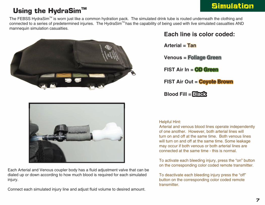
SimulationUsing the HydraSimTM
The FEBSS HydraSimTM is worn just like a common hydration pack. The simulated drink tube is routed underneath the clothing and connected to a series of predetermined injuries. The HydraSimTM has the capability of being used with live simulated casualties AND mannequin simulation casualties.
Each line is color coded:
Arterial = TanTan
Venous = Foliage GreenFoliage Green
FIST Air In = OD GreenOD Green
FIST Air Out = Coyote BrownCoyote Brown
Blood Fill = BlackBlack
connected to a series of predetermined injuries. The HydraSimTM has the capamannequin simulation casualties.
Each Arterial and Venous coupler body has a fl uid adjustment valve that can be dialed up or down according to how much blood is required for each simulated injury.
Connect each simulated injury line and adjust fl uid volume to desired amount.
Helpful Hint:Arterial and venous blood lines operate independently of one another. However, both arterial lines will turn on and off at the same time. Both venous lines will turn on and off at the same time. Some leakage may occur if both venous or both arterial lines are connected at the same time - this is normal.
To activate each bleeding injury, press the “on” button on the corresponding color coded remote transmitter.
To deactivate each bleeding injury press the “off” button on the corresponding color coded remote transmitter.
7

Live Casualty SimulationDuring live casualty simulation, it is recommended that the live simulated casualty operate the HydraSimTM. This allows the casualty to control the amount of pressure applied to their simulated wounds during the training exercise. If dressings and tourniquets are too loose during application, the casualty has the ability to keep their simulated wounds bleeding. This forces the caregiver to continue to treat visible wounds. If dressings and tourniquets have enough pressure on the wounds during applicaton, the casualty has the ability to stop the wounds from bleeding. The live simulated casualty can conceal the HydraSimTM remote transmitters in a pocket or underneath gloved hands.
At the point of injury – activate bleeding wounds
Once treated correctly – deactivate bleeding wounds
When a tourniquet is applied to the extremity of a live simulated casualty, the casualty needs the ability to deactivate the bleeding wound(s) once the tourniquet begins to tighten. When used correctly, tourniquets cause a substantial amount of pain – when the tourniquet begins to tighten and possibly hurt, the casualty must remotely deactivate the bleeding providing the illusion that the treatment worked while preventing an actual tourniquet like effect.
Helpful Hint: Waterproofi ng the remote transmitter with a plastic bag will extend the life of the transmitter.
THE USE OF TORNIQUETS ON LIVE SIMULATED CASUALTIES SHOULD BE CLOSELY MONITORED IN ORDER TO PREVENT INJURY.
8
*Courtesy of Dan Olesnicky, MD, ABEM, ABIM, International School of Tactical Medicine

Vomit Simulation
The HydraSimTM offers a unique vomit simulation confi guration constructed with simple and expendable materials. The HydraSimTM connects to a modifi ed balloon placed in the palm of the live simulated casualty. The casualty makes a fi st blocking the fl uid fl ow causing pressure to build up in the balloon. Once the balloon is pressurized, the casualty moves his or her gloved hand to their mouth and opens their hand. This releases the pressure built up in the balloon and simulates projectile vomiting.
You’ll need:
1 set of nasal cannulla
2 rubber bands
1 long sleeved shirt or coat
1 pair SKEDCO Simulation Gloves
1 balloon – 12” size (preferably black in color)
Constructing the Line
Cut the entire nasal cannulla portion off of the line and slide the cut end of the line into the open end of the balloon. Use 1 Rubber band to secure the balloon to the line making a water tight seal.
Using a pair of scissors, cut a 1” slit into closed end of the balloon.
Measure the line by tracing it up the simulated casualty’s arm toward the simulated drink tube of the HydraSimTM.
Cut the line at the appropriate length and slide a coupling insert into the line.
9
Vomit Simulation

Connecting the Line to the HydraSimTM
Ensure that the HydraSimTM is fi lled with the desired fl uid and connected to its power source.
While wearing both simulation gloves, slide the open end of the balloon through the hole in one of the casualty’s gloves and expose the cut portion of the balloon in the casualty’s palm.
Place the second rubber band around the casualty’s wrist to keep the line from sliding up the casualty’s arm.
Route the line from the casualty’s palm, underneath the casualty’s long sleeved shirt or coat and up the arm to the HydraSimTM simulated drink tube.
Connect the coupling insert of the vomit line to a venous coupler body of the HydraSimTM and ensure that the fl uid adjustment valve is wide open.
Conceal all of the HydraSimTM lines.
Operating the HydraSimTM during Vomit Simulation
The live simulated casualty should make a fi st and then remotely activate the venous line of the HydraSimTM. This will cause the balloon to expand and pressurize.
When the balloon is nearly full, the live simulated casualty should move their gloved hand near their mouth and open their hand. The balloon will rapidly empty and simulate projectile vomiting.
Remotely deactivate the HydraSimTM once vomit simulation is fi nished.
Helpful Hint: Increase the realism of the vomit simulation by using vomit sound effects provided by the live simulated casualty.
10

Mannequin SimulationThe HydraSimTM has the capability of attaching to multiple simulation mannequins allowing the user to “recycle” training equipment they already have. The HydraSimTM is worn by live simulated casualties and mannequin simulated casualties in the same manner. The simulated drink tube is routed underneath the mannequin’s clothing and connected to a series of predetermined injuries. MultiSimTM Fabricated Injuries can be applied to training mannequins in the same manner as live simulated casualties. The user is responsible for remotely activating and deactivating bleeding wounds during the simulation exercise. The HydraSim ™has insertion capability for virtually any type of hollow training mannequin (i.e. Crash Kelly – Laerdal). FEBSS™ Mannequin Modifi cation Kits increase durability of hollow mannequins and allow for joint articulation during bleeding simulation.
FEBSS Impact Simulation Trainer (FIST)TM
FISTTM
Optional Upgrade The FEBSS Impact Simulation Trainer (FIST)TM adds a loud yet safe auditory effect to bleeding simulation by utilizing one of the most common items in the medical community – the examination glove. No pyrotechnics or CO2 compressed gas required.
ics or CO2
11
uired.
*Courtesy of Dan Olesnicky, MD, ABEM, ABIM
International School of Tactical Medicine
*Twist handle to lock and unlock.
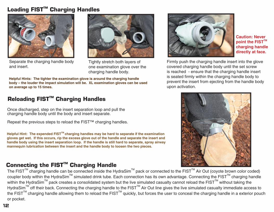
Reloading FISTTM Charging Handles
Once discharged, step on the insert separation loop and pull the charging handle body until the body and insert separate.
Repeat the previous steps to reload the FIST™ charging handles.
Connecting the FISTTM Charging HandleThe FIST
TM charging handle can be connected inside the HydraSim
TM pack or connected to the FIST
TM Air Out (coyote brown color coded)
coupler body within the HydraSimTM
simulated drink tube. Each connection has its own advantage. Connecting the FISTTM
charging handle within the HydraSim
TM pack creates a consolidated system but the live simulated casualty cannot reload the FIST
TM without taking the
HydraSimTM
off their back. Connecting the charging handle to the FISTTM
Air Out line gives the live simulated casualty immediate access to the FIST
TM charging handle allowing them to reload the FIST
TM quickly, but forces the user to conceal the charging handle in a exterior pouch
or pocket.
Loading FISTTM Charging Handles
Separate the charging handle body and insert.
Tightly stretch both layers of one examination glove over the charging handle body.
Firmly push the charging handle insert into the glove covered charging handle body until the set screw is reached - ensure that the charging handle insert is seated fi rmly within the charging handle body to prevent the insert from ejecting from the handle body upon activation.
12
Helpful Hints: The tighter the examination glove is around the charging handle body – the louder the impact simulation will be. XL examination gloves can be used on average up to 15 times.
Helpful Hint: The expended FISTTM charging handles may be hard to separate if the examination gloves get wet. If this occurs, rip the excess glove out of the handle and separate the insert and handle body using the insert separation loop. If the handle is still hard to separate, spray airway mannequin lubrication between the insert and the handle body to loosen the two pieces.
Caution: Never point the FISTTM charging handle directly at face.

Connecting outside the HydraSimTM pack
Ensure the FISTTM charging handle is loaded.
Connect the other end of the FISTTM adapter line to the charging handle coupler body.
Connect one end of the FISTTM adapter line to the FISTTM Air Out line (coyote brown) within the simulated drink tube.
Conceal the loaded FISTTM charging handle with the open end of the handle exposed.
Helpful Hint: Ensure that the open end of the FISTTM charging handle is not covered. Covering the open end of the FISTTM charging handle will muffl e the impact simulation.
Connecting inside the HydraSimTM pack
Connect the other end of the FISTTM adapter line to the charging handle coupler body.
Unzip the HydraSimTM side pocket and top fl ap.
Disconnect the FISTTM Air Out line within the simulated drink tube from the FISTTM Air Out coupler body (coyote brown)
Within the HydraSimTM, place the opened end of the FISTTM charging handle out of the opening near the shoulder strap of the HydraSimTM pack. (top left)
Route a free end of the FISTTM adapter line to the FISTTM Air Out coupler body. (coyote brown)
Connect the FISTTM adapter line to the FISTTM Air Out coupler body. (coyote brown)
13
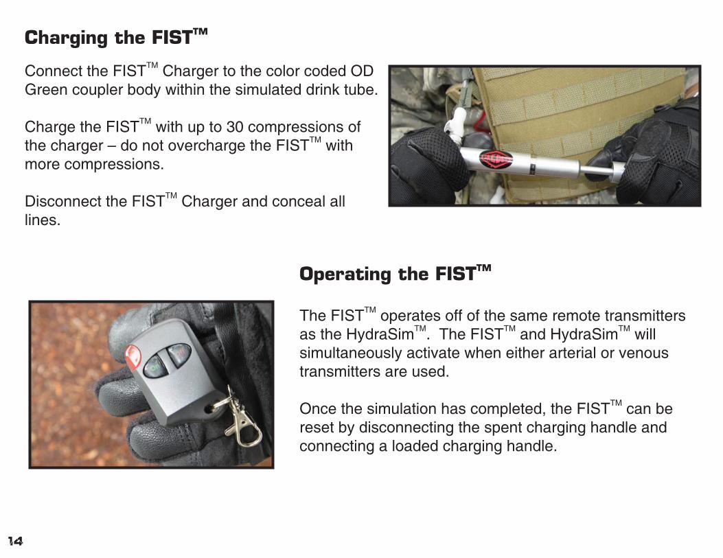
Charging the FISTTM
Connect the FISTTM Charger to the color coded OD Green coupler body within the simulated drink tube.
Charge the FISTTM with up to 30 compressions of the charger – do not overcharge the FISTTM with more compressions.
Disconnect the FISTTM Charger and conceal all lines.
Operating the FISTTM
The FISTTM operates off of the same remote transmitters as the HydraSimTM. The FISTTM and HydraSimTM will simultaneously activate when either arterial or venous transmitters are used.
Once the simulation has completed, the FISTTM can be reset by disconnecting the spent charging handle and connecting a loaded charging handle.
14
MaintenanceMaintenance GuidelinesSKEDCO INC. products are designed to last and we stand behind our one year factory warranty. However, any tampering or activity outside the instructed use will void the warranty for this product.
Battery MaintenanceDisconnect the HydraSimTM battery and recharge after each use.
If stored for an extended amount of time, recharge the battery for 8-10 hours before use.
Remember to unplug the FEBSSTM battery when training is fi nished for the day – failure to do so may result in damage to the FEBSSTM battery.
HydraSimTM Transmitter Battery Maintenance
The HydraSimTM transmitters require a Type 27 - 12 Volt batteries in order to operate correctly. Duracell makes this type of battery and it can be purchased at many retail stores. New HydraSimTM transmitter batteries should be installed when the operational distance of the transmitters has signifi cantly decreased.
Remove the securing screw located on the back of the HydraSimTM transmitter using a Phillips head screwdriver.
Carefully expose the transmitter circuit board and remove the discharged battery paying close attention to the polarity of the terminals.
Install a new battery and replace the circuit board within the enclosure. Then fasten the enclosure together with the securing screw.
Monthly Maintenance: Flushing the HydraSimTM
Empty the Refi ll Tank and wash with warm water. A long brush may be used to scrub the simulation blood residue off of the bottom of the tank.
Once completed, fi ll the Refi ll Tank to the fi ll line with warm water and ensure that no simulation blood remains in the tank.
Install the HydraSimTM battery. Fill the HydraSimTM with clean, warm water.
Connect at least one MultiSimTM Fabricated Injury to the venous and arterial lines ensuring that the fl uid will exit into a sink or bucket.
Activate both venous and arterial lines.
Continue the previous steps until the entire contents of the Refi ll Tank have been fl ushed through the HydraSimTM.
Deactivate the venous and arterial lines and unplug the HydraSimTM battery.15
Troubleshooting tips
Trouble shooting
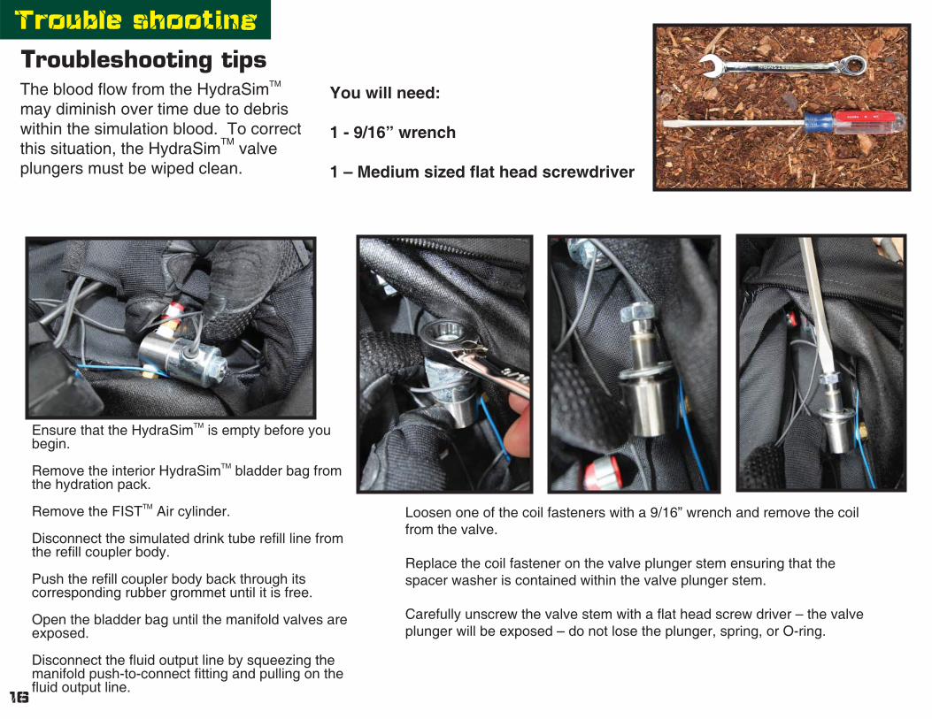
The blood fl ow from the HydraSimTM may diminish over time due to debris within the simulation blood. To correct this situation, the HydraSimTM valve plungers must be wiped clean.
You will need:
1 - 9/16” wrench
1 – Medium sized fl at head screwdriver
Ensure that the HydraSimTM is empty before you begin.
Remove the interior HydraSimTM bladder bag from the hydration pack.
Remove the FISTTM Air cylinder.
Disconnect the simulated drink tube refi ll line from the refi ll coupler body.
Push the refi ll coupler body back through its corresponding rubber grommet until it is free.
Open the bladder bag until the manifold valves are exposed.
Disconnect the fl uid output line by squeezing the manifold push-to-connect fi tting and pulling on the fl uid output line.
Loosen one of the coil fasteners with a 9/16” wrench and remove the coil from the valve.
Replace the coil fastener on the valve plunger stem ensuring that the spacer washer is contained within the valve plunger stem.
Carefully unscrew the valve stem with a fl at head screw driver – the valve plunger will be exposed – do not lose the plunger, spring, or O-ring.
16

Wipe off the rubber plunger and replace the plunger and spring back into the valve stem.
Carefully thread the valve stem back onto the valve body ensuring that the O-ring is seated within the valve body.
Tighten the valve stem with the fl at head screwdriver.
Remove the coil fastener and replace the coil ensuring that the spacer washer separates the coil and the valve body – tighten until snug with the 9/16” wrench – do not over tighten.
Repeat the previous steps on the second valve if needed – DO NOT MIX UP THE VALVE COILS.
Reconnect the fl uid output line by inserting the line into the manifold push-to-connect fi tting until seated. Pull back on the fl uid output line to ensure that the connection is made correctly.
Push the refi ll coupler body back through its corresponding rubber grommet.
Replace the FISTTM Air Cylinder.
Zip up the bladder bag.
Reconnect all coupling inserts to the corresponding color coded coupler bodies.
Replace the interior HyraSimTM bladder bag within the hydration pack.
Fill and bleed air from inside the HydraSimTM before the unit is put back into use.
17
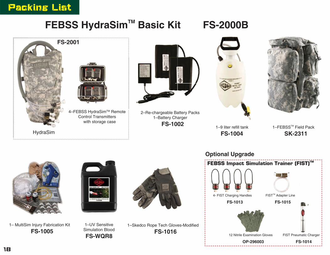
1–9 liter refi ll tank
FS-1004
1– MultiSim Injury Fabrication Kit
FS-1005
2–Re-chargeable Battery Packs1–Battery Charger
FS-1002
4–FEBSS HydraSimTM Remote Control Transmitters
with storage case
FEBSS HydraSimTM Basic Kit FS-2000B
FS-2001
1–FEBSSTM Field Pack
SK-2311
1–UV Sensitive Simulation Blood
FS-WQR8
4–FEBC
FS-2001
HydraSim
1–Skedco Rope Tech Gloves-Modifi ed
FS-1016
18
Packing List
Optional Upgrade
4- FIST Charging Handles
FS-1013
12 Nitrile Examination Gloves
OP-296003
FISTTM Adapter Line
FS-1015
FIST Pneumatic Charger
FS-1014
FEBSS Impact Simulation Trainer (FIST)TM

1–Storm Case
IM2750-00000
1–ACU Simulation Blouse
FS-1006
2–SOF-T Tourniquets
OP-SOF-T
1–ACU Simulation Trouser
FS-1007
2–Emergency Trauma Dressings
OP-FCP-05
Velcro Seam
FEBSSTM Deluxe Kit FS-2000DThe FEBSSTM Deluxe Kit includes all items in the FEBSSTM Basic Kit plus these additional items.
2–QuikClot Combat Gauze moulage Trainer
OP-170
19
Optional Upgrade
4- FIST Charging Handles
FS-1013
12 Nitrile Examination Gloves
OP-296003
Deluxe Packing List
FISTTM Adapter Line
FS-1015
FIST Pneumatic Charger
FS-1014
FEBSS Impact Simulation Trainer (FIST)TM

SKEDCO INC.
Copyright 2010 Skedco Inc. All rights reserved
PO Box 339010505 SW Manhasset DriveTualatin, OR 97062Web Site: www.skedco.com
Tel: 503.691.7909Fax: 503.691.7973
Order: 800.770.SKED (7533)E-mail: [email protected]
“This pain that you hear in someone’s voice when they’re hit and disbelief… You just didn’t want to hear anyone scream anymore. That was the big difference between training and the reality.”
SGT Keni ThomasU.S. Army Ranger
Operation Gothic SerpentOctober 3, 1993
Mogadishu, Somalia