Embed Size (px)
Citation preview

Trehan et al. / J Zhejiang Univ-Sci A (Appl Phys & Eng) 2015 16(9):706-723 706
Informal and formal modelling of engineering processes for
design automation using knowledge based engineering
Vibhor TREHAN, Craig CHAPMAN, Pathmeswaran RAJU (Knowledge Based Engineering (KBE) Lab, Birmingham City University, Birmingham B4 7XG, UK)
E-mail: [email protected]; [email protected]; [email protected]
Received May 29, 2015; Revision accepted Aug. 26, 2015; Crosschecked Aug. 30, 2015
Abstract: Knowledge based engineering (KBE) as a design method helps formulate a comprehensive knowledge base as a virtual prototype which includes design intent, requirements, rationale, and logic along with geometric information, which can then be utilised for representing the product design process, and to achieve complex design automation. One of the identified shortcomings in the field of design process automation using KBE as a holistic approach is a suitable neutral representation technique of a process model with well-defined syntax, axioms, and semantics for it to be shared across multiple platforms and to enable interoperability. To achieve design process automation, two steps are very important. First, a modelling method should be able to informally capture all critical aspects of a process to enable design automation. Second, the informal model should be able to be mapped onto a formal representation technique in a system, which will then enable automation by running a query through this representation. This paper discusses all the critical aspects in the form of design decomposition features and nar-rows down informal modelling approaches based on the criteria formulated for design automation from the literature. Formal representation techniques are discussed with the help of an example to ensure correct mapping of the informal model to a formal representation. The next steps of this research would be recommendation of the formal representation techniques of the informal model based on the discussion in this paper and for future work that will enable process automation. Key words: Knowledge based engineering (KBE), Design automation, Process model, Formal representation, Process
automation doi:10.1631/jzus.A1500140 Document code: A CLC number: TP302
1 Introduction
‘Knowledge based engineering (KBE) repre-sents an evolutionary step in computer-aided engi-neering (CAE) and is an engineering method that represents a merging of object-oriented program-ming (OOP), artificial intelligence (AI), and computer-aided design (CAD) technologies, giving benefit to customised or variant design automation solutions’ (Chapman and Pinfold, 2001). Tradition-ally, in design engineering the output of the prelimi-nary and the detailed design is in the form of a geo-metric CAD model directly created from require-
ments. KBE as a method captures product and process-based data and helps in building a virtual prototype in a system which encapsulates rules, re-quirements, product attributes, features, and ra-tionale for building a geometric model along with downstream processes such as material selection for static and dynamic analysis, and manufacturing ca-pability enabling design automation. A system im-plementation of KBE can be defined as ‘the use of dedicated software language tools in order to cap-ture and re-use product and process engineering knowledge in a convenient and maintainable fash-ion’ (Cooper and LaRocca, 2007). A system imple-menting KBE is dynamic such that it offers true engineering automation including application devel-opment, geometric modelling, application deploy-ment, and tools integration (Egging et al., 2000).
Journal of Zhejiang University-SCIENCE A (Applied Physics & Engineering)
ISSN 1673-565X (Print); ISSN 1862-1775 (Online)
www.zju.edu.cn/jzus; www.springerlink.com
E-mail: [email protected]
ORCID: Vibhor TREHAN, http://orcid.org/0000-0003-2579-8461;Pathmeswaran RAJU, http://orcid.org/0000-0001-8292-4503 © Zhejiang University and Springer-Verlag Berlin Heidelberg 2015

Trehan et al. / J Zhejiang Univ-Sci A (Appl Phys & Eng) 2015 16(9):706-723 707
Investigation of existing KBE methodologies such as knowledge nurture for optimal multidisciplinary analysis and design (KNOMAD) and methodology and tools oriented to knowledge-based engineering applications (MOKA) has revealed some of the shortcomings in the form of neutral representation techniques of a process-based model to enable design process automation. This paper discusses informal process modelling and the formal represen-tation of the informal model. The first part of the paper will discuss various informal process model-ling methods such as integrated definition methods (IDEF) suite, design structure matrix (DSM), Pe-trinet, signposting, role activity diagram (RAD) to capture process-based data along with semiformal modelling methods and languages such as unified modelling language (UML) and systems modelling language (SysML) to capture and represent design features. The next part will discuss existing formal representation techniques such as process specifica-tion language (PSL) and IDEF5 based on a particu-lar logic such that an informal or semiformal model can then be mapped onto a suitable formal tech-nique. The formal representation framework will have well-defined syntax, axioms, and semantics and will be compliant with international standards for product model definition and process exchange (Grüninger and Menzel, 2003; Pouchard et al., 2005). 2 Background of KBE methodologies
There are various methodologies for imple-menting KBE. A methodology termed as KOM-PRESSA with its diagrammatic ways of capturing knowledge in the form of a component diagram was initiated for smaller KBE applications (Bancroft et al., 2000; Chapman et al., 2007). In knowledge cap-ture methodology (KCM), capturing and structuring of knowledge is performed from a designer’s point of view. It breaks down the product knowledge into parts, assemblies, features, and the relationships be-tween the geometric features and the components to formulate product semantics (Terpenny et al., 2000; Chapman et al., 2007). Both KOMPRESSA and KCM were targeted for product modelling and au-tomation. KNOMAD as a methodology laid empha-
sis on activity diagrams for processes and represen-tation of multidisciplinary knowledge including de-sign and manufacturing (Verhagen et al., 2012). MOKA (Skarka, 2007) as a methodology was initi-ated for larger applications. It encapsulated both product and process based modelling. It lays empha-sis on two stages of the KBE life cycle as shown in Fig. 1. First it captures knowledge in an informal manner in the form of ICARE (illustration, con-straints, activities, rules, and entities) and then con-verts it to a formal manner. MOKA utilised UML notation and extended it to develop MOKA model-ling language (MML) as a means of producing a formal knowledge model (Stokes, 2001; Chapman et al., 2007). In spite of strengths in managing engi-neering knowledge throughout the product life cycle MOKA was revealed to have a few shortcomings, e.g., MML did not comply with Object Modelling Group (OMG) requirements (Abdullah et al., 2005); the formal knowledge model could not be mapped to a KBE system to assist in process automation (Prasad, 2006; Chapman et al., 2007).
This piece of research initially intends to bridge this gap in correct syntactical and semantic mapping of an informal process-based model capturing all the necessary design process features to a neutral formal representation framework. The subsequent step will focus on recommendation of neutral formal repre-sentation methods based on discussion and experi-mentation, which should then be able to achieve the purpose of design process automation through a que-ry layer. 3 Process modelling for design automation using KBE
There are many methods of capturing and rep-
resenting knowledge for a KBE system. The ap-proach that will be followed as part of this research aligns its concepts to object process methodology (OPM) whose feature is that it breaks down the knowledge into three types of entities: objects, pro-cesses, and states with objects and processes being higher level building blocks (Dori, 2002). OPM is also recognized as an International Standards Organ-ization (ISO) standard in the form of ISO/PRF PAS 19450 (Dori, 2002).

Trehan et al. / J Zhejiang Univ-Sci A (Appl Phys & Eng) 2015 16(9):706-723 708
The OPM methodology keeps systems as the viewpoint and enables merger of object-oriented and process-oriented modelling. The states are indicated by links, which exist as both structural and proce-dural links representing the static and dynamic be-haviour of objects in a system. OPM allows for fea-tures such as inheritance, and aggregation of objects and their properties. It offers object-process lan-guage (OPL) and object-process diagram (OPD) as a means of formal representation of the informal representation (Dori et al., 2003; 2010). The OPL enables java code generation and automatic genera-tion of UML diagrams and natural text output. Per-taining to this research, the formal representation of the entire process model should enable code genera-tion for fulfilling the purpose of process automation.
According to the National Institute of Stand-ards and Technology (NIST), a ‘process model for product realisation is defined as a computer–interpretable representation of human and machine activities and their interactions required for realisa-tion of a product. This may include early concept and configuration design activities, detailed design,
prototyping, testing, tooling, fabrication, assembly and other activities within the scope of the realisa-tion process’ (Lyons et al., 1995). There are many governing factors for selecting a process modelling technique. Some of the existing purposes are task scheduling, resource allocation, cost-quality-time trade-offs, and process improvement in terms of design-to-market lead time (Smith and Morrow, 1999).
In order for a process-based model to be inter-preted by KBE systems to achieve automation of processes, the process modelling technique should broadly satisfy the following functions:
(1) Inter-dependencies between tasks to enable flow of information such as inputs, enablers, mech-anisms into multiple tasks which will enable de-pendency backtracking in the formal representation in the system.
(2) Design process decomposition to the high-est level of abstraction of artefacts, which includes all features such as design rationale, attributes of a process and product with states and behaviour along with resources and requirements. This also includes
Fig. 1 MOKA methodology in KBE life cycle (Reprinted from (Lohith et al., 2013), Copyright 2013, with permission from CSREA)

Trehan et al. / J Zhejiang Univ-Sci A (Appl Phys & Eng) 2015 16(9):706-723 709
control mechanisms and enablers for a process for failure modes through existing rules, constraints and logic for successful process adherence and comple-tion. These may be in the form of geometrical toler-ances, manufacturing constraints or material selec-tion information for a design process.
(3) Object-process relationship by breakdown of the knowledge content primarily in the form of objects and if possible simultaneous representation of governing entire processes altering the state and behaviour of the object.
(4) Computational capability indicating that all aspects of the process model can be mapped to a software system or formally stored in a system with well-defined syntax and axioms which can then be queried to achieve process automation (Chapman and Pinfold, 1999; 2001; Egging et al., 2000; Prasad, 2006; Chapman et al., 2007; Cooper and LaRocca, 2007; Skarka, 2007; Lohith et al., 2013).
The process modelling techniques discussed will be analysed for various functions as described below:
(a) Task scheduling and sequential planning; (b) Cost/Time/Quality trade-off; (c) Inter-dependencies between tasks; (d) Design process decomposition; (e) Object-process relationship; (f) Computational capability. Thus, techniques which satisfy the stated crite-
ria out of all described functions will be carried forward for formal representation. 4 Informal process modelling techniques
Techniques such as design structure matrix (DSM), work transformation matrix (WTM), IDEF suite, Petrinet, event process chain diagram (EPC), signposting, RAD, UML/SysML, and business pro-cess modelling notation (BPMN) will be discussed in this section. A process modelling technique based on a matrix structure for sequencing and scheduling is a DSM (Eppinger et al., 1994). DSM lays empha-sis on activity dependencies and can focus on com-plicated processes with more than 100 tasks (Smith and Morrow, 1999). It helps in assessment of risks throughout the design process along with failure modes (Amigo et al., 2013). However, one of the
limitations of DSM is the lack of ability to manage tasks within an iterative group. WTM is a process modelling method which helps in decomposition of a larger task into small processes (Smith and Eppinger, 1997). It is derived from DSM with a modification that the non-diagonal elements in the matrix are rep-resented by re-work quantity. However, a major shortcoming of WTM modelling is the assumption of computation of re-work as a linear function of work from a previous iteration, which is not true in all cases. Both the techniques have strength in mod-elling interdependencies of tasks but fail to capture all of the necessary design decomposition features.
Process modelling techniques such as Petrinet and EPC fulfill the purpose of measurement of productivity of a process and work flow modelling (Amigo et al., 2013). Petrinet is based on nodes and arcs to represent information (Murata, 1989). One of the limitations of Petrinet is its inability to consider time as a process variable (Browning et al., 2006). Petrinet fails to capture contextual information alt-hough it can be used for modelling of interdepend-encies of tasks (Stacey et al., 2000). To capture con-textual information, modifications can be made to Petrinet. For example, NIST researchers used modi-fied Petrinet (MPN) in an object-oriented methodol-ogy to include additional information such as mech-anisms and rules for governing failure modes along with resources in the form of people, machines, and tools to implement computer-aided concurrent engi-neering (CACE) (Lyons et al., 1995). Thus, MPN can be used to indicate inter-dependencies within a process along with design decomposition features. An EPC helps in generating tools for benchmarking along with documentation of design data (Browning, 2009; Amigo et al., 2013). EPC fails to capture de-sign decomposition features, but MPN allows the capturing of design decomposition features.
A modelling method, initially for representing manufacturing systems, but which progressed to the design process is integrated definition for functional modelling (IDEF0) (Colquhoun et al., 1993; PUBS, 1993). It was derived from structured analysis and design technique (SADT). An IDEF0 model com-prises of a set of activity boxes referred as ICOM (input, control, output, and mechanism). The top level box is the highest fidelity model and can be represented elaborately in more detail using lower

Trehan et al. / J Zhejiang Univ-Sci A (Appl Phys & Eng) 2015 16(9):706-723 710
fidelity models (Colquhoun et al., 1993; Gingele et al., 2002). The ICOM activity box for IDEF0 is il-lustrated in Fig. 2.
Although IDEF0 was found to be a very de-
tailed graphical representation of the processes (Al-Ahmari and Ridgway, 1999) with all the control pa-rameters, it was considered to be time-consuming. A major shortcoming of the IDEF0 approach was its lack of consideration of time as a variable. IDEF1 was introduced after IDEF0 and was based on in-formation modelling instead of IDEF0 functional modelling. It shows the relation between constraints and is based on entity relationships (Mayer, 1992; Lyons et al., 1995). IDEF1 lays emphasis on repre-senting information based on a class of entities with attributes to define their behaviour (Lu et al., 1996). Thus, it can be used to model real world objects as well as information required to manage an enter-prise. IDEF2 was introduced to address a major shortcoming of earlier IDEFX versions for their lack of inclusion of time. It was supposed to be dynamic but was not successfully implemented in commercial systems (Lyons et al., 1995). IDEF3 shows the rela-tion and logical flow of activities within a process. It is referred to as a process description capture method with time-based behaviour of activities. Another
advantage of IDEF3 was that it can show two views of the process, one termed process flow network (PFN) which lays emphasis on activity and the other object state transition network (OSTN) which al-lows an object—centered view (Plaia and Carrie, 1995; Knutilla et al., 1998). The IDEF3 process de-scription method lays emphasis on the flow of junc-tions, which embeds the time varying behaviour of activities.
IDEF4 is an object-oriented design process de-scription and broadly consists of two models—class and method sub-models with diagrams such as pro-tocol, inheritance, and taxonomy diagrams which can be interlinked and sufficiently capture all intri-cate parts of a process (Mayer et al., 1992). The complete IDEF suite, however, adopts slightly dif-ferent methods to capture process information, as illustrated. IDEF0 focusses on function modelling, IDEF1 focusses on information modelling, IDEF2 on simulation modelling, IDEF3 on detailed flow of junctions in a process flow, IDEF4 on object-oriented design, and IDEF5 on ontology-based de-scription (Plaia and Carrie, 1995). IDEF4 will be discussed in detail in the next section to verify whether it satisfies the requirements for design pro-cess automation. IDEF5 will be discussed under ‘formal representation methods’.
A role activity diagram (RAD) enables a graph-ic view of the process with interactions between var-ious processes. It allows an object-oriented view of the process with changes in behaviour of the object with activities (Aguilar-Savén, 2004). However, one of the limitations of RAD is its inability to decom-pose the high level processes to lower levels of pro-cess with precise details. RAD can be used to model workflows for improvement. RAD can be visualised through MS Visio (Shukla et al., 2014), but it cap-tures high level aspects with activities assigned to roles for a particular system but does not capture design decomposition features as stated in the re-quirements for design automation.
A data flow diagram (DFD) shows the flow of process data and information graphically. It enables decomposition of the process to a lower level of de-tail (Aguilar-Savén, 2004) in contrast to RAD. It allows functional modelling and thus has conceptual similarities to IDEF0. However, it fails to capture all design decomposition features.
Fig. 2 IDEF0 higher fidelity activity box with an example (Reprinted from (PUBS, 1993), Copyright 1993, with permission from Knowledge Based Systems, Inc.)
Trehan et al. / J Zhejiang Univ-Sci A (Appl Phys & Eng) 2015 16(9):706-723 711
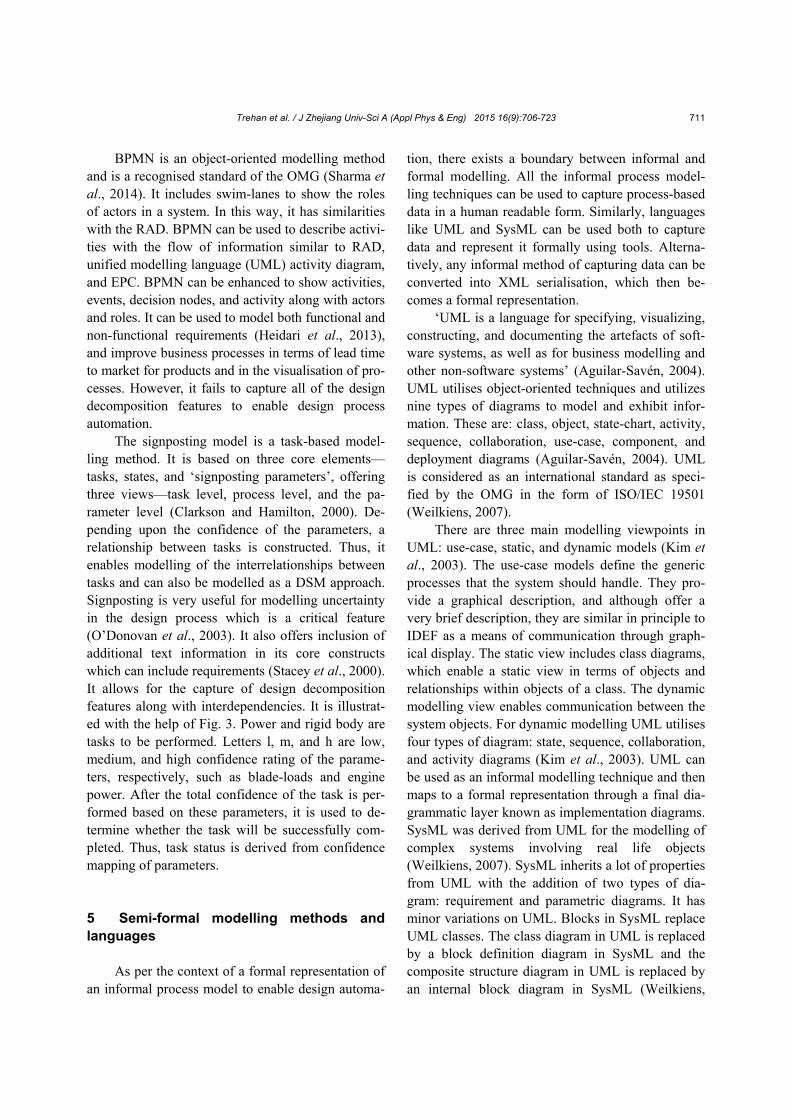
BPMN is an object-oriented modelling method and is a recognised standard of the OMG (Sharma et al., 2014). It includes swim-lanes to show the roles of actors in a system. In this way, it has similarities with the RAD. BPMN can be used to describe activi-ties with the flow of information similar to RAD, unified modelling language (UML) activity diagram, and EPC. BPMN can be enhanced to show activities, events, decision nodes, and activity along with actors and roles. It can be used to model both functional and non-functional requirements (Heidari et al., 2013), and improve business processes in terms of lead time to market for products and in the visualisation of pro-cesses. However, it fails to capture all of the design decomposition features to enable design process automation.
The signposting model is a task-based model-ling method. It is based on three core elements— tasks, states, and ‘signposting parameters’, offering three views—task level, process level, and the pa-rameter level (Clarkson and Hamilton, 2000). De-pending upon the confidence of the parameters, a relationship between tasks is constructed. Thus, it enables modelling of the interrelationships between tasks and can also be modelled as a DSM approach. Signposting is very useful for modelling uncertainty in the design process which is a critical feature (O’Donovan et al., 2003). It also offers inclusion of additional text information in its core constructs which can include requirements (Stacey et al., 2000). It allows for the capture of design decomposition features along with interdependencies. It is illustrat-ed with the help of Fig. 3. Power and rigid body are tasks to be performed. Letters l, m, and h are low, medium, and high confidence rating of the parame-ters, respectively, such as blade-loads and engine power. After the total confidence of the task is per-formed based on these parameters, it is used to de-termine whether the task will be successfully com-pleted. Thus, task status is derived from confidence mapping of parameters.
5 Semi-formal modelling methods and languages
As per the context of a formal representation of
an informal process model to enable design automa-
tion, there exists a boundary between informal and formal modelling. All the informal process model-ling techniques can be used to capture process-based data in a human readable form. Similarly, languages like UML and SysML can be used both to capture data and represent it formally using tools. Alterna-tively, any informal method of capturing data can be converted into XML serialisation, which then be-comes a formal representation.
‘UML is a language for specifying, visualizing, constructing, and documenting the artefacts of soft-ware systems, as well as for business modelling and other non-software systems’ (Aguilar-Savén, 2004). UML utilises object-oriented techniques and utilizes nine types of diagrams to model and exhibit infor-mation. These are: class, object, state-chart, activity, sequence, collaboration, use-case, component, and deployment diagrams (Aguilar-Savén, 2004). UML is considered as an international standard as speci-fied by the OMG in the form of ISO/IEC 19501 (Weilkiens, 2007).
There are three main modelling viewpoints in UML: use-case, static, and dynamic models (Kim et al., 2003). The use-case models define the generic processes that the system should handle. They pro-vide a graphical description, and although offer a very brief description, they are similar in principle to IDEF as a means of communication through graph-ical display. The static view includes class diagrams, which enable a static view in terms of objects and relationships within objects of a class. The dynamic modelling view enables communication between the system objects. For dynamic modelling UML utilises four types of diagram: state, sequence, collaboration, and activity diagrams (Kim et al., 2003). UML can be used as an informal modelling technique and then maps to a formal representation through a final dia-grammatic layer known as implementation diagrams. SysML was derived from UML for the modelling of complex systems involving real life objects (Weilkiens, 2007). SysML inherits a lot of properties from UML with the addition of two types of dia-gram: requirement and parametric diagrams. It has minor variations on UML. Blocks in SysML replace UML classes. The class diagram in UML is replaced by a block definition diagram in SysML and the composite structure diagram in UML is replaced by an internal block diagram in SysML (Weilkiens,

Trehan et al. / J Zhejiang Univ-Sci A (Appl Phys & Eng) 2015 16(9):706-723 712
2007). A very important point about SysML is that the models can be exchanged via a neutral format in the form of ISO AP233 (discussed later). Both UML and SysML with multiple viewpoints can exhibit and represent design decomposition features along with interdependencies of tasks.
IDEF4 as a derivation of IDEF features but with a focus on object-oriented technique is similar to UML in terms of layering and process views. Both are object-oriented modelling techniques which are necessary for capturing processes and representing in a neutral format for process automa-tion. ‘IDEF4 is an object-oriented design method for developing component-based client server systems. It has been designed to support smooth transition from the application domain and requirements anal-ysis models to the design and to actual source code generation’ (Mayer et al., 1992). IDEF4 provides three layers: system design, application design, and low-level design. Thus, it decomposes design into higher level of abstraction. Along with the three design models, IDEF4 includes a design rationale component. In IDEF4, symbols such as O, R, L, M, A, and E are used to denote objects, relations, links, methods, attributes, and events, respectively (Mayer et al., 1992). Thus, its concepts become similar to UML by focusing on object-oriented modelling and by providing multiple layers of the
design process. However, the design rationale com-ponent in IDEF4 is an additional feature and pro-vides the designer with a wider view of the design data. This makes IDEF4 suitable for capturing all of the design decomposition features required for pro-cess automation. It also enables inter-dependencies between tasks along with illustrating changes in the state of an object with governing processes propa-gating throughout the model with object-oriented modelling. 6 Comparative analysis of informal and semiformal process modelling methods and languages
As stated earlier, the majority of process model-ling techniques for knowledge acquisition or captur-ing can be visualized or edited with the help of exist-ing tools. Some examples are—use of SIMAN/ ARENA tool for simulation of IDEF0 (Al-Ahmari and Ridgway, 1999), ProCAP for IDEF3 (Grüninger, 2009), and CAM for construction and visualisation of signposting (Wynn et al., 2010). Thus, computa-tional capability will be excluded from the criteria in the analysis table because any process-based method of capture can be converted into XML syntax and stored in a system with a formal representation. The
Fig. 3 Using signposting to derive task status from confidence mapping of parameters (Reprinted from (Clarkson and Hamilton, 2000), Copyright 2000, with permission from Springer-Verlag London Ltd.)

Trehan et al. / J Zhejiang Univ-Sci A (Appl Phys & Eng) 2015 16(9):706-723 713
other three criteria, i.e., inter-dependencies between tasks, design process decomposition, and object-process relationship, will be the most important functions in evaluating whether a process model can broadly capture enough information which when mapped onto a formal representation can achieve process automation. The analysis is shown in Table 1. 7 Formal modelling and representation techniques
Process models can be shared across multiple domains using different representation techniques, but this may have problems due to syntax, semantics, and axioms. The objective of the following discus-sion is to discuss and narrow down a few existing neutral formal representation techniques of the in-formal model in terms of these issues that should help integration with multiple platforms. The next step would be running a query on the formal repre-sentation of the informal model, which will lead to an automation process from the neutral representa-tion using KBE. This query stage will not be dis-cussed here.
There are many existing process representa-tions. Some of them are the knowledge interchange format (KIF), process specification language (PSL), standard for the exchange of product model data (STEP as ISO 10303), and IDEF5 (Knutilla et al., 1998). PSL and IDEF5 are ontology-based represen-tations. Some of the other ontology-based represen-tations are common plan representation (CPR), workflow process definition language (WPDL), and planning domain definition language (PDDL). An ontology-based approach helps formalise the con-cepts and provides axioms as a formal means of con-straining the meaning of the concepts in the lan-guage. Ontology is defined as the taxonomy of con-cepts and their definitions supported by a logical theory. Ontology defines a set of terms, entities and objects, classes and relationships along with formal definitions and axioms to constrain the meaning of terms (Pouchard et al., 2000). Thus, ontology ena-bles interoperability and re-usability of the data us-ing common semantics of modelled information. The ontologies for WPDL and PDDL do provide com-
mon semantics but are unable to provide axioms as a formal means of maintaining the semantics in the language (Grüninger, 2004). CPR (Pease, 1998) was initiated by the Defense Advanced Research Projects Agency (DARPA)-sponsored object model working group (OMWG). The basic concepts in CPR are ac-tion resource, actor, and objective with additional concepts such as plan and time point. However, CPR as a language does not enable representation of all design decomposition features through its ontology.
OWL is a web ontology language for creating and sharing ontologies on the World Wide Web and is regarded as a W3C recommendation (Bechhofer, 2009). OWL was developed as an extension of the resource description framework (RDF) and is de-rived from the DAML+OIL ontology. OWL has three variants: OWL Lite, OWL DL, and OWL Full. OWL Lite offers ease of implementation but offers the least of the OWL constructs. OWL DL is based on descriptive logic and offers more constructs and, more importantly, reasoning ability. OWL Full of-fers the most comprehensive constructs but deviates from reasoning ability and offers less ease of compu-tation compared to OWL DL.
OWL-S, as a semantic markup for web services built on OWL, enables viewing of process with in-puts, outputs, parameters, precondition, and results (Martin et al., 2004). Thus, selection of a particular OWL language is critical to represent design decom-position features (Bechhofer, 2009; W3C, 2012). RDF offers representation of information over the World Wide Web and is regarded as a W3C recom-mendation (Klyne and Carroll, 2004; Manola et al., 2004). The syntax of RDF describes information by breaking it into a triple form consisting of subject, object, and predicate. It also offers a formal graph-ical syntax in the form of an RDF Graph. The uni-form resource identifier (URI) is an id which locates the address of the information over the web. The most critical aspect of RDF is that it uses XML-based syntax and schema (Klyne and Carroll, 2004).
KIF (Genesereth and Fikes, 1992) as a computer-oriented language was developed by the Interlingua Working Group of the DARPA knowledge sharing effort (Knutilla et al., 1998). It has formally defined semantics and breaks down knowledge into the form of objects with related attributes, processes, and functions. Thus, it aligns its methodology with OPM

Trehan et al. / J Zhejiang Univ-Sci A (Appl Phys & Eng) 2015 16(9):706-723 714
Table 1 Analysis of informal and semiformal process modelling methods and languages for capturing knowledge to enable design process automation
Process modelling methods & languages
Purpose
References Task
scheduling/ sequential planning
Cost/Time /Quality trade-off
Required for design process automation Inter-
dependencies between tasks
Design pro-cess decom-
position
Object- process
relationshipDSM Eppinger et al., 1994; Smith and
Morrow, 1999; Browning, 2009; Amigo et al., 2013
WTM Smith and Eppinger, 1997; Smith and Morrow, 1999; Amigo et al., 2013
Petrinet Lyons et al., 1995; Knutilla et al., 1998; Grüninger and Menzel, 2003; Browning et al., 2006; Amigo et al., 2013
MPN (e.g., Coloured Petrinet, Timed
Petrinet)
Lyons et al., 1995; Knutilla et al., 1998; Aguilar-Savén, 2004; Browning et al., 2006; Amigo et al., 2013
EPC Browning, 2009; Amigo et al., 2013
IDEF0, 1, 2, 3, 4, 5
Mayer et al., 1992; 1995; PUBS, 1993; Colquhoun et al., 1993; Lyons et al., 1995; Plaia and Carrie, 1995; Knutilla et al., 1998; Al-Ahmari and Ridgway, 1999; Gingele et al., 2002; Grüninger and Menzel, 2003; Aguilar-Savén, 2004; Browning, 2009; Amigo et al., 2013
RAD Holt et al., 1983; Badica et al., 2003; 2005; Aguilar-Savén, 2004; Badica and Badica, 2011; Shukla et al., 2014
DFD Colquhoun et al., 1993; Al-Ahmari and Ridgway, 1999; Aguilar-Savén, 2004; Amigo et al., 2013
Signposting Clarkson and Hamilton, 2000; Stacey et al., 2000; Brown-ing, 2002; O’Donovan et al., 2003; Browning et al., 2006; Baxter et al., 2007; Wynn et al., 2010; Amigo et al., 2013
UML, SysML
Booch et al., 1999; Pooley and King, 1999; Vernadat, 2002; Kim et al., 2003; Chen and Chen, 2005; Weilkiens, 2007; Plateaux et al., 2009; Badica and Badica, 2011; Nan, 2012; Sharma et al., 2014
BPMN
Badica and Badica, 2011; Scheuerlein et al., 2012; Amigo et al., 2013; Heidari et al., 2013; Sharma et al., 2014

Trehan et al. / J Zhejiang Univ-Sci A (Appl Phys & Eng) 2015 16(9):706-723 715
(Dori, 2002) and solves a major issue of pre-defined formal semantics. As stated earlier, OPM as ISO 19450 forms a part of ISO TC 184/SC5 (Dori, 2002). ISO TC 184 is managed by the ISO and covers ‘standardization in the field of industrial automation and integration concerning discrete part manufactur-ing and encompassing the applications of multiple technologies, i.e., information systems, machines and equipment and telecommunications’ (Pouchard et al., 2005).
To address the shortcoming of formulating common semantics and as a standard for the ex-change of process specification, PSL was designed to facilitate correct and complete exchange of pro-cess information among manufacturing systems, such as scheduling, process modelling, process plan-ning, production planning, simulation, project man-agement, work flow, and business process re-engineering (Grüninger and Menzel, 2003). A major purpose of PSL was to enable interoperability of processes utilising different process models and pro-cess representations (Pouchard et al., 2005). PSL ontology is written in KIF format and forms ISO 18629 as an integral part of ISO TC 184 (Pouchard et al., 2005). PSL ontology is based on the first-order logic (Pouchard et al., 2000). Ontologies based on the first-order logic exhibit more expressiveness com-pared to descriptive logic and can run inference on the modelled information. PSL architecture consists of two parts: PSL core (foundation theories) and a set of extensions which can be mapped to EXPRESS schemas, UML and XML (Grüninger and Cutting-Decelle, 2000; Pouchard et al., 2005). PSL ontology is divided into the following four theories: core theo-ries, duration and ordering theories, resource theories, and actor and agent theories (Grüninger, 2004). The PSL core provides four kinds of elements: object, activity, activity occurrence, and time point. To rep-resent an activity-based description, PSL uses an activity role declaration (ARD) along with object declarations to describe objects being affected by the activities of the process (Grüninger and Menzel, 2003). The extensions allow for temporal relations between activities. Thus, the use of extensions with experimentation may be used for representing design decomposition features other than the core theory.
Another important ISO standard for product da-ta exchange is STEP which is also regarded as ISO
10303 (Pratt, 2001). STEP is widely used in industry for representing and exchanging CAD data in a neu-tral format (Wenzel et al., 2011). STEP not only co-vers exchange of geometric information between different CAD formats but includes all product data throughout the life cycle (Lützenberger et al., 2012). STEP also uses EXPRESS as a modelling language to represent objects with related attributes and prop-erties. STEP allows various formats for product data representation. Some examples are: ISO 10303-21 for text format, ISO 10303-28 for XML serialization, ISO 10303-22 for API, ISO 10303-41 for product identification and product configuration, and ISO 10303-46 for visual representation (Weilkiens, 2007). STEP, UML, parts library (PLIB), PSL, and manu-facturing management data exchange (MANDATE) are examples of standardized exchange specifica-tions for sharing of product and process information in industrial data (Chandrasegaran et al., 2013). As PSL deals with standardized syntax and semantic sharing of modelled information, it is consistent with ISO 10303, ISO 13584 (PLIB), and ISO 15531 (MANDATE) (Grüninger and Cutting-Decelle, 2000). STEP as ISO 10303, PSL as ISO 18629 along with MANDATE as ISO 15531 all comprise part of ISO TC 184/SC4.
SysML is a language that can be used for cap-turing and representing of process-based data for a complex system and can be viewed as a formal rep-resentation with the help of tools such as visual par-adigm. SysML models, once created, can be ex-changed via ISO AP 233 of STEP. Some of the im-portant APs of STEP for consideration are AP233, AP213, Part49, and AP242 for formal storage of informal process models. Other individual formats such as rule interchange format (RIF) offer a neutral representation technique for rules, logic, and con-straints. RIF offers a major advantage as it can be expressed in both XML-based syntax and more im-portantly can be extended to AP242 of STEP (Lützenberger et al., 2012). It can integrate with any platform or a CAD/PDM platform (Colombo et al., 2014). RuleML is another format for representing and sharing of rules on the World Wide Web. It is based upon XML, RDF, and OWL (Boley et al., 2005). Table 2 illustrates some of the available for-mal representation methods for some of the design decomposition features.

Trehan et al. / J Zhejiang Univ-Sci A (Appl Phys & Eng) 2015 16(9):706-723 716
IDEF5 is an ontology-based formal representa-
tion based on the basic concepts of IDEF suite. It is also written in KIF format and is based on the first-order logic (Perakath et al., 1994). The IDEF5 on-tology language comprises two languages: the IDEF5 schematic language and the IDEF5 elabora-tion language. The schematic language is a graphical language that allows input of information through an automated ontology capture tool. The elaboration language is a structured text language with full ex-pressive power of the first-order logic which allows input of information with detailed context (Perakath et al., 1994). It enables storage and representation of classes, kinds, and the first- and second-order rela-tions as well through the ontology. 8 Mapping example: manual translation of an informal process to formal representation
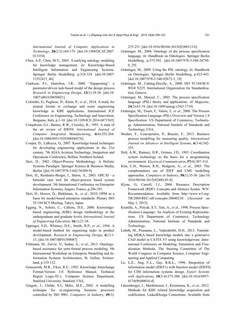
An informal process capturing design aspects of fan blades has been derived and compiled in a process map illustrating inputs, enablers, parameters, requirements, rules and rationale, logic, behavior, and attributes along with the object primarily defined as a blade (Amoo, 2013). The process map captures all aspects of a process which IDEF4 captures but does not demonstrate the IDEF4 syntax in the form of a static, dynamic, and behavioural models in the
present shape. The activities or events are broken down into three basic steps: blade geometry optimi-sation, dovetail attachment, and material selection as shown in Fig. 4 along with other design decomposi-tion features. Fig. 5 illustrates the object box for the blade.
The formal representation framework is based on the discussion for representing process infor-mation along with other design decomposition fea-tures such as rules, logic, rationale, and requirements along with flow of information in the form of inputs and outputs. PSL ARD and object declaration syntax is explained as follows:
(define-activity-role :id <number>* :name <string> :successors <number>* :preconditions <PSL sentence>* :postconditions <PSL sentence>*)
(Grüninger and Menzel, 2003) (define-object :name <KIF constant> :constraints <PSL sentence>*)
(Grüninger and Menzel, 2003) (define-parameter :variable <KIF variable> :constraints <PSL sentence>*)
(Grüninger and Menzel, 2003)
Table 2 Formal representation methods & techniques available for representing design decomposition features to enable design process automation
Design decomposition features
Formal representation methods & techniques
References
Process–inputs, outputs, and parameters
PSL, IDEF5, OWL-S, STEP Perakath et al., 1994; Knutilla et al., 1998; Grüninger and Cutting-Decelle, 2000; Grüninger et al., 2000; Pouchard et al., 2000; 2005; Pratt, 2001; Zha and Du, 2002; Grüninger and Menzel, 2003; Bock and Grüninger, 2004; Grüninger, 2004; Martin et al., 2004; Chen and Chen, 2005; Bechhofer, 2009; Grüninger, 2009; Lützenberger et al., 2012; W3C, 2012; Fellmann et al., 2013
Engineering rules, logic, constraints, rationale
RuleML, RIF, OWL DL Boley et al., 2005; Bechhofer, 2009; Lützenberger et al., 2012; W3C, 2012; Fellmann et al., 2013; Colombo et al., 2014
Requirement Requirements interchange format (ReqIF), SysML requirements
diagram
Weilkiens, 2007; Lützenberger et al., 2012; Fellmann et al., 2013; OMG, 2013; Colombo et al., 2014

Trehan et al. / J Zhejiang Univ-Sci A (Appl Phys & Eng) 2015 16(9):706-723 717
The object declaration can be a constant as shown in the first object declaration or a variable as shown in the next object declaration. The PSL syn-tax illustrating the flow of information along with extensions to illustrate parameters along with inputs and outputs is shown as follows, but only for blade geometry optimisation.
(define-parameter :variable ?fb :constraints (fan blade ?fb)) (define-activity-role :id s1 :name Blade geometry optimisation :successors 2 :preconditions (existing design of ?fb(beginof ?occ)) :postconditions (preliminary optimal geometric design features of ?fb(endof ?occ)))
The parameters and inputs for blade geometry
optimisation are broken down informally as follows: Parameters: incremental lift created by each
blade, ideal power and proper airfoil section, twist, chord, and pitch angle for optimal thrust distribution.
Inputs: aerodynamic forces acting on a local airfoil and global changes in momentum along with rate of air intake (Amoo, 2013). The formal syntax in PSL incorporating extensions is as follows:
(forall (?s1 ?l ?p ?t ?fm ?r) (implies (= ?s1 Blade geometry optimization (?l ?p ?t ?fm ?r)) (and (activity_occurrence ?s1
(Incremental Lift created by each blade ?l) (Ideal power ?p) (Proper airfoil section, twist, chord, and
Fig. 5 The object box as per IDEF4 methodology
Fig. 4 Example of an informal process capturing design aspects of a fan blade

Trehan et al. / J Zhejiang Univ-Sci A (Appl Phys & Eng) 2015 16(9):706-723 718
pitch angle for optimal thrust distribution ?t) (Aerodynamic forces acting on a local air-foil and global changes in momentum ?fm)
(Rate of air intake ?r)))) (forall (?fb ?s1) (implies (or (occurrence-input ?fb ?s1) (occurrence-output ?fb ?s1)
(and (object ?fb) (not (state ?fb)) (activity_occurrence ?s1))))) (forall (?fb ?s1) (iff (participant ?fb ?s1) (exists (?t) (participates_in ?fb ?s1 ?t)))) (forall (?fb ?s1) (implies (or (occurrence-input ?fb ?s1) (occurrence-output ?fb ?s1)) (participant ?fb ?s1)))
(exists (?s1 ?l ?p ?t ?fm ?r) (and (occurrence_of ?s1 Blade geometry op-timisation(?l ?p ?t ?fm ?r)
(occurrence-input ?fm ?r ?s1) (occurrence-output ?fm ?r ?s1))) (forall (?fb ?s1 ?f) (implies (or (input-state ?fb ?s1 ?f)
(output-state ?fb ?s1 ?f) (and (object ?fb) (not (state ?fb) (activity_occurrence ?s1) (state ?f)))))) (forall (?fb ?s1 ?f) (implies (input-state ?fb ?s1 ?f) (and (occurrence-input ?fb ?s1) (prior ?f ?s1) (exists_at ?fb (begin_of ?s1))))) (forall (?fb ?s1 ?f) (implies (output-state ?fb ?s1 ?f) (and (occurrence-output ?fb ?s1) (achieved ?f ?s1) (exists_at ?fb (end_of ?s1)))))
A few examples of the design rules to be fol-
lowed during the blade geometry optimisation pro-cess are represented in RuleML (Boley et al., 2005) as follows: a 30% hollowing in a hollow fan blade results in about a 13%–16% decrease in torsional rigidity compared to a solid blade design (Amoo, 2013).
rule ml declaration (implication) <Implies> <head> <Atom> <Rel>hollowing</Rel> <Ind>30%</Ind> <Var>hollow fan blade</Var> <Rel>compared to a solid blade design</Rel> </Atom> </head> <body> <Atom> <Rel>decrease</Rel> <Ind>13%–16%</Ind> <Var>torsional rigidity</Var> </Atom> </body> </Implies>
The rate of air intake varies and is dictated by
factors such as airfoil geometry, angle of attack, air density, and the speed at which the airfoil moves through the air (Amoo, 2013).
rule ml declaration (statement) <Atom> <Var>rate of air intake</Var> <Rel>dictated by factors such as</Rel> <Var>airfoil geometry</Var> <Var>angle of attack</Var> <Var>air density</Var>
<Var>speed at which the airfoil moves through the air</Var>
</Atom>
The functional requirement as derived from the process for blade geometry optimisation is that the fan blades spin to accelerate a mass of air into the engine to generate thrust that propels the aircraft forward. Approximately 80% of the thrust produced by a modern jet engine is delivered by the fan. Fan blades also function to reduce total engine damage from the ingestion of various foreign objects such as birds by radially deflecting outward such objects rather than passing them through to the core parts of the engine (Amoo, 2013). The functional require-ments of the process are captured and represented in a SysML requirement diagram as shown in Fig. 6.

Trehan et al. / J Zhejiang Univ-Sci A (Appl Phys & Eng) 2015 16(9):706-723 719
The underlying schema of the requirement (Fig. 6) is the textual requirement, identifier, source, kind, method, risk, and status. The model can be ex-changed via AP233 of STEP. 9 Discussion
From the observations in Table 1, IDEF suite with main emphasis on IDEF4, UML/SysML, Modi-fied Petrinet, and signposting satisfy the criteria as they successfully capture necessary design decom-position features on a higher level. Petrinet is con-sidered to be one of the methods for process model-ling and representation techniques. Although in its original form, it does not enable design decomposi-tion to the required level for process automation, MPN can capture design decomposition features. However, it fails to utilise common semantics and uniformity in axioms (Grüninger and Menzel, 2003). This highly inhibits its use in a neutral representation for achieving automation.
Final selection of an informal model would be suggested after experimentation on formal represen-tation of the informal model, as all of the necessary design decomposition features in the form of param-eters, inputs and outputs, rationale, logic, rules, con-straints, attributes, and requirements will need to be formally represented.
As seen with the help of the mapping example, PSL enables process representation with parameters, inputs, and outputs using core theory and extensions in the ontology. It will need more experimentation to illustrate representation of other design decomposi-tion features such as constraints and attributes. RuleML (Boley et al., 2005) can be implemented to exhibit for textual rules and rationale. Similarly SysML can exhibit requirements. The framework will need integration for simultaneous application. PSL can be directly mapped to UML and hence to the SysML requirement diagram. RuleML and PSL can be integrated and shared via XML schemas. Similarly, all formats and languages to be experi-mented for representing other design decomposition features will need integration.
10 Conclusions
Methods and languages such as the IDEF suite, UML/SysML, and signposting informally capture most design decomposition features such as objects, processes with inputs, outputs along with resources, attributes, requirements, rules, logic, constraints, and rationale for design process automation. The formal representation framework as discussed with the help of the cited example aims to achieve process auto-mation by representing all design decomposition
Fig. 6 SysML requirement diagram for representing requirements of the design aspects of the fan blades process

Trehan et al. / J Zhejiang Univ-Sci A (Appl Phys & Eng) 2015 16(9):706-723 720
features dynamically in a knowledge model and then running a query. To optimally recommend a formal representation framework, other formal representa-tion methods such as STEP schemas for process rep-resentation (Part49), OWL-S, and IDEF5 will be experimented with use-case data. Functional markup language (FML), behaviour markup language (BML) for representing engineering process functionality and behaviour, and MathML for representing math-ematical information will be experimented with the cited examples. Similarly, formats such as ReqIF (OMG, 2013) for exhibiting requirements will be compared to the SysML requirements diagram, RIF for rules will be compared to RuleML, and common logic interchange format (CLIF) (Pan and Liu, 2010; Sowa, 2011) and OWL DL for logic will be experi-mented on and compared with the examples cited. The comparison of various formal representation methods and successful integration upon testing and validation will yield a complete formal representa-tion framework of the inferred informal knowledge model, which will enable process automation through a query layer. References Abdullah, M.S., Evans, A., Benest, I., et al., 2005.
Developing a UML profile for modelling knowledge-based systems. In: Model Driven Architecture. Springer Berlin Heidelberg, p.220-233. [doi:10.1007/11538097_ 15]
Aguilar-Savén, R.S., 2004. Business process modelling: review and framework. International Journal of Production Economics, 90(2):129-149. [doi:10.1016/ S0925-5273(03)00102-6]
Al-Ahmari, A.M.A., Ridgway, K., 1999. An integrated modelling method to support manufacturing systems analysis and design. Computers in Industry, 38(3):225-238. [doi:10.1016/S0166-3615(98)00094-3]
Amigo, C.R., Iritani, D.R., Rozenfeld, H., et al., 2013. Product development process modeling: state of the art and classification. In: Smart Product Engineering. Springer Berlin Heidelberg, p.169-179. [doi:10.1007/ 978-3-642-30817-8_17]
Amoo, L.M., 2013. On the design and structural analysis of jet engine fan blade structures. Progress in Aerospace Sciences, 60:1-11. [doi:10.1016/j.paerosci.2012.08.002]
Badica, A., Badica, C., 2011. Formal Verification of Business Processes as Role Activity Diagrams. Proceedings of the Federated Conference on Computer Science and Infor-mation Systems, Szczecin, Poland, p.277-280.
Badica, C., Badica, A., Litoiu, V., 2003. Role activity diagrams as finite state processes. 2nd International
Symposium on Parallel and Distributed Computing, Ljubljana, Slovenia. [doi:10.1109/ISPDC.2003.1267638]
Badica, C., Teodorescu, M., Spahiu, C., et al., 2005. Integrating role activity diagrams and hybrid IDEF for business process modeling using MDA. Seventh International Symposium on Symbolic and Numerical Algorithms for Scientific Computing, Timisoara, Romania, p.71-74. [doi:10.1109/SYNASC.2005.40]
Bancroft, C.N., Crump, S.J., Lovett, P.J., et al., 2000. Taking KBE into the foundry. Proceedings of the 7th ISPE International Conference On Concurrent Engineering, Lyon, France, 24:17-20.
Baxter, D., Gao, J., Case, K., et al., 2007. An engineering design knowledge reuse methodology using process modelling. Research in Engineering Design, 18(1):37-48. [doi:10.1007/s00163-007-0028-8]
Bechhofer, S., 2009. OWL: Web Ontology Language. In: Encyclopedia of Database Systems. Springer US, p.2008-2009.
Bock, C., Grüninger, M., 2004. Inputs and Outputs in the Process Specification Language. US Department of Commerce, Technology Administration, National Institute of Standards and Technology.
Boley, H., Grosof, B., Tabet, S., 2005. RuleML Tutorial. Available from http://ruleml.org/papers/tutorial-ruleml-20050513.html [Accessed on Apr. 1, 2015].
Booch, G., Rumbaugh, J., Jacobson, I., 1999. The Unified Modeling Language User Guide. Pearson Education, India.
Browning, T.R., 2002. Process integration using the design structure matrix. Systems Engineering, 5(3):180-193. [doi:10.1002/sys.10023]
Browning, T.R., 2009. The many views of a process: toward a process architecture framework for product development processes. Systems Engineering, 12(1):69-90. [doi:10. 1002/sys.20109]
Browning, T.R., Fricke, E., Negele, H., 2006. Key concepts in modeling product development processes. Systems Engineering, 9(2):104-128. [doi:10.1002/sys.20047]
Chandrasegaran, S.K., Ramani, K., Sriram, R.D., et al., 2013. The evolution, challenges, and future of knowledge representation in product design systems. Computer-Aided Design, 45(2):204-228. [doi:10.1016/j.cad.2012. 08.006]
Chapman, C., Pinfold, M., 1999. Design engineering—a need to rethink the solution using knowledge based engineering. Knowledge-Based Systems, 12(5-6):257-267. [doi:10.1016/S0950-7051(99)00013-1]
Chapman, C., Pinfold, M., 2001. The application of a knowledge based engineering approach to the rapid design and analysis of an automotive structure. Advances in Engineering Software, 32(12):903-912. [doi:10.1016/ S0965-9978(01)00041-2]
Chapman, C., Preston, S., Pinfold, M., et al., 2007. Utilising enterprise knowledge with knowledge-based engineering.
Trehan et al. / J Zhejiang Univ-Sci A (Appl Phys & Eng) 2015 16(9):706-723 721
International Journal of Computer Applications in Technology, 28(2-3):169-179. [doi:10.1504/IJCAT.2007. 013354]
Chen, A.P., Chen, M.Y., 2005. A unifying ontology modeling for knowledge management. In: Knowledge-Based Intelligent Information and Engineering Systems. Springer Berlin Heidelberg, p.318-324. [doi:10.1007/ 11552413_46]
Clarkson, P.J., Hamilton, J.R., 2000. “Signposting”, a parameter-driven task-based model of the design process. Research in Engineering Design, 12(1):18-38. [doi:10. 1007/s001630050021]
Colombo, G., Pugliese, D., Klein, P., et al., 2014. A study for neutral format to exchange and reuse engineering knowledge in KBE applications. International ICE Conference on Engineering, Technology and Innovation, Bergamo, Italy, p.1-10. [doi:10.1109/ICE.2014.6871565]
Colquhoun, G.J., Baines, R.W., Crossley, R., 1993. A state of the art review of IDEF0. International Journal of Computer Integrated Manufacturing, 6(4):252-264. [doi:10.1080/09511929308944576]
Cooper, D., LaRocca, G., 2007. Knowledge-based techniques for developing engineering applications in the 21st century. 7th AIAA Aviation Technology, Integration and Operations Conference, Belfast, Northern Ireland.
Dori, D., 2002. Object-Process Methodology: A Holistic Systems Paradigm. Springer Science & Business Media, Berlin. [doi:10.1007/978-3-642-56209-9]
Dori, D., Reinhartz-Berger, I., Sturm, A., 2003. OPCAT—a bimodal case tool for object-process based system development. 5th International Conference on Enterprise Information Systems, Angers, France, p.286-291.
Dori, D., Howes, D., Blekhman, A., et al., 2010. OPM as a basis for model-based enterprise standards. Plenary ISO TC184/SC5 Meeting, Tokyo, Japan.
Egging, N., Scholz, C., Calkins, D.E., 2000. Knowledge-based engineering (KBE) design methodology at the undergraduate and graduate levels. International Journal of Engineering Education, 16(1):21-38.
Eppinger, S.D., Whitney, D.E., Smith, R.P., et al., 1994. A model-based method for organizing tasks in product development. Research in Engineering Design, 6(1):1-13. [doi:10.1007/BF01588087]
Fellmann, M., Zarvić, N., Sudau, A., et al., 2013. Ontology-based assistance for semi-formal process modeling. 5th International Workshop on Enterprise Modelling and In-formation Systems Architectures, St. Gallen, Switzer-land, p.119-132.
Genesereth, M.R., Fikes, R.E., 1992. Knowledge Interchange Format-Version 3.0: Reference Manual. Technical Report Logic-92-1, Computer Science Department, Stanford University, Stanford, USA.
Gingele, J., Childe, S.J., Miles, M.E., 2002. A modelling technique for re-engineering business processes controlled by ISO 9001. Computers in Industry, 49(3):
235-251. [doi:10.1016/S0166-3615(02)00113-6] Grüninger, M., 2004. Ontology of the process specification
language. In: Handbook on Ontologies. Springer Berlin Heidelberg, p.575-592. [doi:10.1007/978-3-540-24750-0_29]
Grüninger, M., 2009. Using the PSL ontology. In: Handbook on Ontologies. Springer Berlin Heidelberg, p.423-443. [doi:10.1007/978-3-540-92673-3_19]
Grüninger, M., Cutting-Decelle, A., 2000. ISO TC184/SC4/ WG8 N225. International Organization for Standardiza-tion, Geneva.
Grüninger, M., Menzel, C., 2003. The process specification language (PSL) theory and applications. AI Magazine, 24(3):63-74. [doi:10.1609/aimag.v24i3.1719]
Grüninger, M., Tissot, F., Valois, J., et al., 2000. The Process Specification Language (PSL) Overview and Version 1.0 Specification. US Department of Commerce, Technolo-gy Administration, National Institute of Standards and Technology, USA.
Heidari, F., Loucopoulos, P., Brazier, F., 2013. Business process modelling for measuring quality. International Journal on Advances in Intelligent Systems, 6(3-4):342-355.
Holt, A.W., Ramsey, H.R., Grimes, J.D., 1983. Coordination system technology as the basis for a programming environment. Electrical Communication, 57(4):307-314.
Kim, C.H., Weston, R.H., Hodgson, A., et al., 2003. The complementary use of IDEF and UML modelling approaches. Computers in Industry, 50(1):35-56. [doi:10. 1016/S0166-3615(02)00145-8]
Klyne, G., Carroll, J.J., 2004. Resource Description Framework (RDF): Concepts and Abstract Syntax. W3C Recommendation. Available from http://www.w3.org/ TR/2004/REC-rdf-concepts-20040210/ [Accessed on May 1, 2015].
Knutilla, A., Polyak, S.T., Tate, A., et al., 1998. Process Spec-ification Language: An Analysis of Existing Representa-tions. US Department of Commerce, Technology Administration, National Institute of Standards and Technology.
Lohith, M., Prasanna, L., Vaderahobli, D.H., 2013. Translat-ing MOKA based knowledge models into a generative CAD model in CATIA V5 using knowledgeware. Inter-national Conference on Modeling, Simulation and Visu-alization Methods, The Steering Committee of The World Congress in Computer Science, Computer Engi-neering and Applied Computing.
Lu, L.Z., Ang, C.L., Gay, R.K.L., 1996. Integration of information model (IDEF1) with function model (IDEF0) for CIM information systems design. Expert Systems with Applications, 10(3-4):373-380. [doi:10.1016/0957-4174(96)00016-4]
Lützenberger, J., Marthinusen, I., Kristensen, K., et al., 2012. Methods for KBE related knowledge acquisition and codification. LinkedDesign Consortium. Available from

Trehan et al. / J Zhejiang Univ-Sci A (Appl Phys & Eng) 2015 16(9):706-723 722
http://www.linkeddesign.eu/files/LinkedDesign_Deliverable_6.1.pdf [Accessed on Feb. 1, 2015].
Lyons, K.W., Duffey, M.R., Anderson, R.C., 1995. Product Realization Process Modeling: a Study of Requirements, Methods and Research Issues. National Institute of Standards and Technology, Gaithersburg, USA.
Manola, F., Miller, E., McBride, B., 2004. RDF Primer. W3C recommendation. Available from http://www.w3.org/TR/ 2004/REC-rdf-primer-20040210/ [Accessed on May 1, 2015].
Martin, D., Burstein, M., Hobbs, J., et al., 2004. OWL-S: Semantic Markup for Web Services. W3C member submission. Available from http://www.w3.org/ Submission/OWL-S/ [Accessed on June 1, 2015].
Mayer, R.J., 1992. IDEF1 Information Modeling. Technical Report No. AFWAL-TR-81-4023, Knowledge Based Systems, Inc., Texas.
Mayer, R.J., Keen, A.A., Wells, M.S., 1992. Information Integration for Concurrent Engineering (IICE) IDEF4 Object-Oriented Design Method Report. Technical Report No. KBSI-IICE-90-STR-01-0592-01, Knowledge Based Systems, Inc., Texas.
Mayer, R.J., Menzel, C.P., Painter, M.K., et al., 1995. Information Integration for Concurrent Engineering (IICE) IDEF3 Process Description Capture Method Report. Technical Report No. KBSI-IICE-90-STR-01-0592-02, Knowledge Based Systems, Inc., Texas.
Murata, T., 1989. Petri nets: properties, analysis and applications. Proceedings of the IEEE, 77(4):541-580. [doi:10.1109/5.24143]
Nan, J., 2012. Design Automation Systems–Supporting Documentation and Knowledge Management. Master Thesis, Jönköping University, Jönköping, Sweden.
O’Donovan, B.D., Clarkson, P.J., Eckert, C.M., 2003. Signposting: modelling uncertainty in design processes. Proceedings of ICED 03, the 14th International Conference on Engineering Design, Stockholm, Sweden.
OMG (Object Management Group), 2013. Requirements Interchange Format (ReqIF) Version 1.1. Available from http://www.omg.org/spec/ReqIF/1.1/PDF/.
Pan, W.L., Liu, D.X., 2010. Mapping object role modeling into common logic interchange format. 3rd International Conference on Advanced Computer Theory and Engi-neering, Chengdu, China, p.V2-104-V2-109. [doi:10. 1109/ICACTE.2010.5579141]
Pease, A., 1998. Core Plan Representation. Object Model Focus Group.
Perakath, B., Menzel, C.P., Mayer, R.J., et al., 1994. Information Integration for Concurrent Engineering (IICE) IDEF5 Method Report. Technical Report, Knowledge Based Systems, Inc., Texas.
Plaia, A., Carrie, A., 1995. Application and assessment of IDEF3-process flow description capture method. Inter-national Journal of Operations & Production Manage-ment, 15(1):63-73. [doi:10.1108/01443579510077214]
Plateaux, R., Choley, J.Y., Penas, O., et al., 2009. Towards an integrated mechatronic design process. IEEE Interna-tional Conference on Mechatronics, p.1-6.
Pooley, R., King, P., 1999. The unified modelling language and performance engineering. IEE Proceedings-Software, 146(1):2-10. [doi:10.1049/ip-sen:19990151]
Pouchard, L., Ivezic, N., Schlenoff, C., 2000. Ontology engi-neering for distributed collaboration in manufacturing. Proceedings of the AIS2000 Conference.
Pouchard, L.C., Cutting-Decelle, A.F., Michel, J.J., et al., 2005. ISO 18629 PSL: a standardised language for spec-ifying and exchanging process information. Proceeding of the 16th International Federation of Automatic Con-trol World Congress, Prague, Czechoslovakia, p.4-8.
Prasad, B., 2006. Best Practices in Knowledge-based Engineering (KBE)-Catia Operators Exchange (COE) Report. Technical Report. [doi:10.13140/2.1.4370.5602]
Pratt, M.J., 2001. Introduction to ISO 10303—the STEP standard for product data exchange. Journal of Compu-ting and Information Science in Engineering, 1(1):102-103. [doi:10.1115/1.1354995]
PUBS, 1993. Announcing the Standard for Integration Definition for Function Modelling (IDEF0). Draft Federal Information Processing Standards Publication, Texas.
Scheuerlein, H., Rauchfuss, F., Dittmar, Y., et al., 2012. New methods for clinical pathways—business process model-ing notation (BPMN) and tangible business process modeling (t.BPM). Langenbeck's Archives of Surgery, 397(5):755-761. [doi:10.1007/s00423-012-0914-z]
Sharma, D.K., Hitesh, Rao, V., 2014. Configurable business process modeling notation. IEEE International Advance Computing Conference, Gurgaon, India, p.1424-1429. [doi:10.1109/IAdCC.2014.6779535]
Shukla, N., Keast, J.E., Ceglarek, D., 2014. Improved work-flow modelling using role activity diagram-based model-ling with application to a radiology service case study. Computer Methods and Programs in Biomedicine, 116(3):274-298. [doi:10.1016/j.cmpb.2014.05.005]
Skarka, W., 2007. Application of MOKA methodology in generative model creation using CATIA. Engineering Applications of Artificial Intelligence, 20(5):677-690. [doi:10.1016/j.engappai.2006.11.019]
Smith, R.P., Eppinger, S.D., 1997. Identifying controlling features of engineering design iteration. Management Science, 43(3):276-293. [doi:10.1287/mnsc.43.3.276]
Smith, R.P., Morrow, J.A., 1999. Product development pro-cess modeling. Design Studies, 20(3):237-261. [doi:10. 1016/S0142-694X(98)00018-0]
Sowa, J., 2011. Introduction to Common Logic. Available from http://www.jfsowa.com/talks/clintro.pdf [Accessed on Apr. 1, 2015].
Stacey, M., Clarkson, P.J., Eckert, C., 2000. Signposting: an AI approach to supporting human decision making in design. Proceedings of DETC’00 ASME 2000 Design
Trehan et al. / J Zhejiang Univ-Sci A (Appl Phys & Eng) 2015 16(9):706-723 723
Engineering Technical Conferences and Computers and Information in Engineering Conference, Baltimore, USA.
Stokes, M., 2001. Managing Engineering Knowledge: MOKA: Methodology for Knowledge Based Engineer-ing Applications. Professional Engineering Publishing, Bury St Edmunds, UK.
Terpenny, J.P., Strong, S., Wang, J., 2000. A methodology for knowledge discovery and classification. 10th Flexible Automation and Intelligent Manufacturing Conference, p.22-32.
Verhagen, W.J.C., Bermell-Garcia, P., van Dijk, R.E.C., et al., 2012. A critical review of knowledge-based engineering: an identification of research challenges. Advanced Engineering Informatics, 26(1):5-15. [doi:10.1016/j.aei. 2011.06.004]
Vernadat, F., 2002. UEML: towards a unified enterprise modelling language. International Journal of Production Research, 40(17):4309-4321. [doi:10.1080/00207540210 159626]
W3C (Word Wide Web Consortium), 2012. OWL 2 Web Ontology Language Document Overview. W3C Recommendation. Available from http://www.w3.org/ TR/owl2-overview/ [Accessed on June 1, 2015].
Weilkiens, T., 2007. Systems Engineering with SysML/UML. The MK/OMG Press, p.1-22. [doi:10.1016/B978-0-12-374274-2.00001-8]
Wenzel, H., Gondhalekar, A., Balachandran, L., et al., 2011. Automated generation of Isight-models through a neutral workflow description. SIMULIA Customer Conference, Barcelona, Spain.
Wynn, D.C., Wyatt, D.F., Nair, S.M.T., et al., 2010. An intro-duction to the Cambridge Advanced Modeller. Proceed-ings of the 1st International Conference on Modelling and Management of Engineering Processes, Cambridge, UK.
Zha, X., Du, H., 2002. A PDES/STEP-based model and system for concurrent integrated design and assembly planning. Computer-Aided Design, 34(14):1087-1110. [doi:10.1016/S0010-4485(01)00186-5]
中文概要
题 目:基于知识工程的设计自动化工程步骤的非规范
化和规范化建模
目 的:目前基于知识工程的设计过程自动化领域有一
个缺陷,即缺乏一个语法、语义、公理完善的
过程模型表示技术以便在不同平台之间共享,
从而实现互操作。研究期望通过两个关键步骤
来实现设计过程自动化。
方 法:1. 对非规范化建模方法进行分析对比(表 1);
2. 分析过程建模技术应该满足的功能,细化成
不同的要点对不规范的建模方法进行分析对
比,同时分析可以表示不同设计分解特征的规
范建模技术。
结 论:1. 明确了设计过程自动化的两个关键步骤:
(1)非规范化地获取设计过程中的关键点,
(2)将非规范化模型映射为规范化表示;
2. 分析得出表示不同设计分解特征的规范化表
示方法和技术(表 2);3. 根据分析结果,可以
选择最优的非规范化和规范化建模方法,从而
支持设计过程自动化。
关键词:基于知识的工程;设计自动化;过程模型;规
范化表示;过程自动化