Embed Size (px)
Citation preview

©A
BB
Pow
er P
rodu
cts
AB
-1-
Mar
ch20
07
Información clave en la especificación de
Filtros
Håkan Rörvall
Harmonic filters and applications
Jornadas Técnicas
25& 26 April.
Chile.

©A
BB
Pow
er P
rodu
cts,
HV
Pro
duct
s -2
ContainsPower Quality
•Cost running parameters
•Filter types
•Filter design
•Synchronized switching

©A
BB
Pow
er P
rodu
cts,
HV
Pro
duct
s -3
Cost running parameter
What generates the cost
� Engineering costs for specification of filtersSpecify the work to be done or the solution?
� Several solutions might do the job
� Parameters that have effect on the filter hardware costAim with filterSpecial demands and environment conditions
� Generated ( design ) harmonics and distortion demandsThe feeding networkType of filter BP; HP; C-filterProtection scheme

©A
BB
Pow
er P
rodu
cts,
HV
Pro
duct
s -4
Cost running parameter
Engineering costs for design of filters
� At User / User Consultant or Hardware Supplier
� Specify the work to be done or the solution?How to define the most competitive solutionThe system responsibility depends on influence
� Several solutions might do the job
� What is most important at evaluation scope or function?

©A
BB
Pow
er P
rodu
cts,
HV
Pro
duct
s -5
Aim with compensation, what is the need ?
� Reactive power needed, neglecteble harmonics on the busCapacitor bank(s with damping reactors )
� Reactive power needed, with harmonics on the busbut no extra distortion demands.Capacitor bank with anti resonance Compensation (strong detuned filters)
� Reactive power need, problems with harmonics on the bus and distortion demands.Filter(s)Selection of filter type BP; HP; C
Power Quality
©A
BB
Pow
er P
rodu
cts,
HV
Pro
duct
s -6
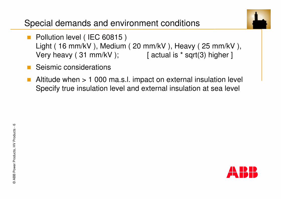
Special demands and environment conditions
� Pollution level ( IEC 60815 )Light ( 16 mm/kV ), Medium ( 20 mm/kV ), Heavy ( 25 mm/kV ), Very heavy ( 31 mm/kV ); [ actual is * sqrt(3) higher ]
� Seismic considerations
� Altitude when > 1 000 ma.s.l. impact on external insulation levelSpecify true insulation level and external insulation at sea level

©A
BB
Pow
er P
rodu
cts,
HV
Pro
duct
s -7
Special demands and environment conditions
�
Altitude correction factor
0,90
1,00
1,10
1,20
1,30
1,40
1,50
1,60
1,70
1,80
1,90
2,00
0
200
400
600
800
1000
1200
1400
1600
1800
2000
2200
2400
2600
2800
3000
3200
3400
3600
3800
4000
4200
4400
Altitude above sea level
Cor
rect
ion
fact
or *
BIL
IEC 60071-2 [exp (h/8150 )]
IEC 60694 [exp((h-1000)/8150 )] ; IEC 60044-1
IEC 60726 [6,25 % / 500 m ]
IEEE C57.12.00-1987 ; NBR10671/1989
IEEE Std 281

©A
BB
Pow
er P
rodu
cts,
HV
Pro
duct
s -8
Cost running parameter feeding network
� System voltage and insulation levelNetwork ( system ) impedance ( short-circuit power )Low short-circuit power problem for voltage distortion High short-circuit power problem for current distortion Other capacitive loads
� Voltage level
� Voltage fluctuations
� Frequency fluctuations

©A
BB
Pow
er P
rodu
cts,
HV
Pro
duct
s -9
Cost running parameter
The filter itself
� Number of branchesDistortion demandsVoltage raise at connection
� Type of filter (s)
Indoor filter with iron core

©A
BB
Pow
er P
rodu
cts,
HV
Pro
duct
s -1
0
Cost running parameter / Capacitor bank
Important difference installed power vs generated power
� Generated power is based on the line voltage to which the usefulpower refers. This is not effected by harmonic content and/or safety margins
� Installed power is based on design voltage voltage including extra safety margins
2syst12
2
gen U*C**1n
nQ ωωωω
−−−−====
2
2 n
nsyst2
2
1inst )C*
IU*
1nn
(*C*Q ����∞∞∞∞
ωωωω++++
−−−−ωωωω====

©A
BB
Pow
er P
rodu
cts,
HV
Pro
duct
s -1
1
Cost running parameter / Capacitor bank
Example:
Assume a network :
13,8 kV, 50 Hz ± 1 %
Ssc =800 MVA
Load / Harmonic source
6- pulse 18 MVA rectifier with harmonic generation according to table
6,1185037
6,5175035
7,3155031
7,8145029
13,1125025
13,1115023
19,895019
22,185017
46,365013
54,855011
107,63507
165,72505
11,31503
I [ A ]f [ Hz ]Order
Power Quality

©A
BB
Pow
er P
rodu
cts,
HV
Pro
duct
s -1
2
Cost running parameter / Capacitor bank
Filter system
BP-filter n=4,85
with Qgen = 9 Mvar
L=2,99 mH ± 2%C=144 µF ± 5 % ± dT- dEf = 50 Hz ± 1,0 %
dT temperature tolerance
dE element failure tolerance
Order Minimum Nominal MaximumFundamental 8278 8321 8359
3 14 15 175 1071 593 4297 134 111 9711 30 26 2413 20 18 1617 7 6 619 6 5 423 3 3 225 3 2 229 1 1 131 1 1 135 1 1 137 1 1 1
Sum harmonics 1292 783 601 VTotal sum 9571 9104 8960 V
Installed power 12,434 11,252 10,899 Mvar
Capacitor voltageComponent tolerance

©A
BB
Pow
er P
rodu
cts,
HV
Pro
duct
s -1
3
Cost running parameter / Capacitor bank
The capacitor bank power is ~ U²� According to standard the capacitor units shall be able to operate
at 110 % of rated voltage
� According to standard the capacitor voltage shall be calculated as the arithmetic sum of fundamental and harmonic voltages
� Design voltage and current shall consider tolerances of components and fluctuations in network conditions
� Bank power and voltageOptimization

©A
BB
Pow
er P
rodu
cts,
HV
Pro
duct
s -1
4
Cost running parameter / Capacitor bank margins
Order Minimum Nominal Maximum Order Minimum Nominal MaximumFundamental 8278 8321 8359 Fundamental 8278 8321 8359
3 14 15 17 3 14 15 175 1071 593 429 5 1071 593 4297 134 111 97 7 134 111 9711 30 26 24 11 30 26 2413 20 18 16 13 20 18 1617 7 6 6 17 7 6 619 6 5 4 19 6 5 423 3 3 2 23 3 3 225 3 2 2 25 3 2 229 1 1 1 29 1 1 131 1 1 1 31 1 1 135 1 1 1 35 1 1 137 1 1 1 37 1 1 1
Sum harmonics 1292 783 601 V Sum harmonics 1292 783 601 VTotal sum 9571 9104 8960 V Total sum 9571 9104 8960 V
Installed power 12,434 11,252 10,899 Mvar Installed power 12,434 11,252 10,899 MvarPower change 0,0% 0,0% 0,0%
Fundamental safety margin 0%Harmonic safety margin 0%
Component tolerance Component tolerance

©A
BB
Pow
er P
rodu
cts,
HV
Pro
duct
s -1
5
Cost running parameter / Reactor
� Reactor power ~2*pi*f*L*I²
� Design spectra
� Loss demands ( loss evaluation )
� Short-circuit current / Thermal load current ( if > 25 rule of thumb )
� Insulation demands across terminals and to earth
©A
BB
Pow
er P
rodu
cts,
HV
Pro
duct
s -1
6
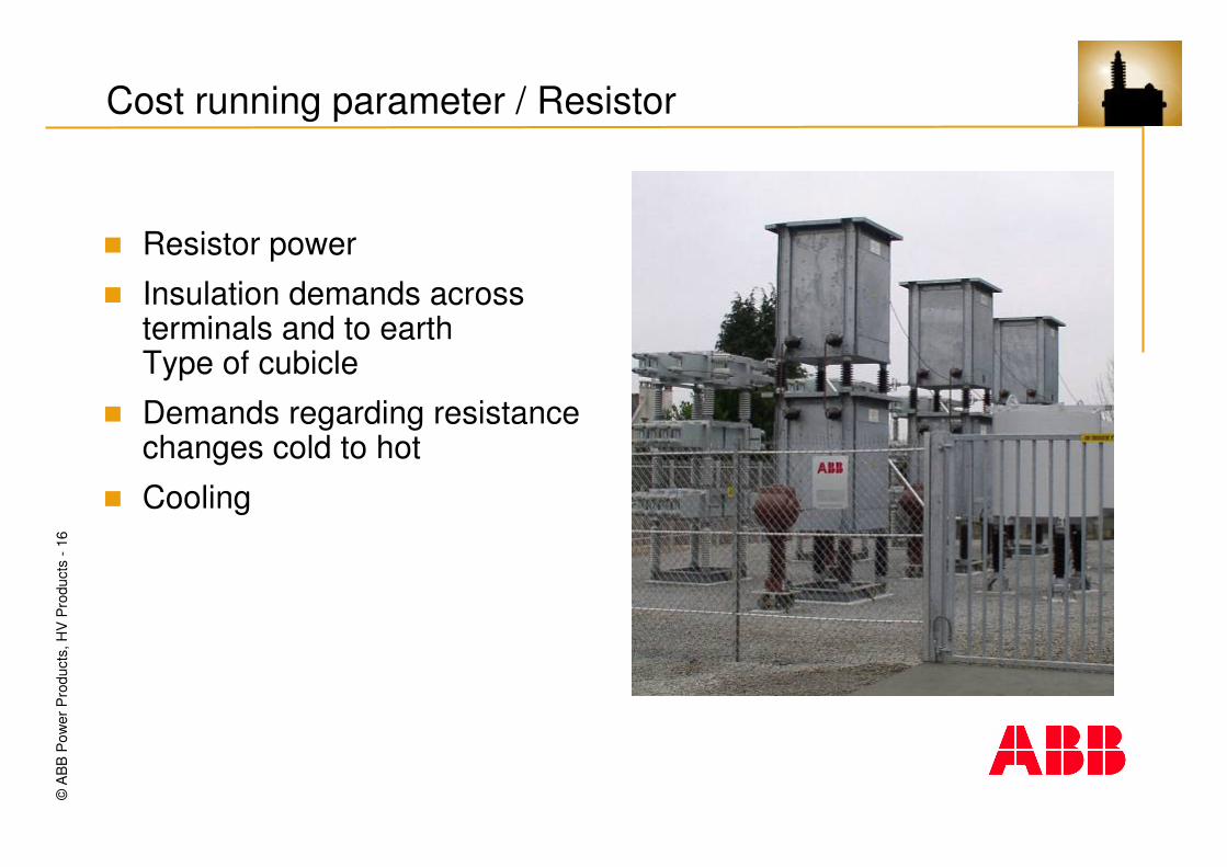
Cost running parameter / Resistor
� Resistor power
� Insulation demands acrossterminals and to earth Type of cubicle
� Demands regarding resistance changes cold to hot
� Cooling

©A
BB
Pow
er P
rodu
cts,
HV
Pro
duct
s -1
7
Cost running parameter summary
Main parameters when external conditions is given
� Capacitor bankInstalled power, design power ( I.e. based on design voltage )
� ReactorReactor power, Inductance and design current spectra
� ResistorResistor power, Insulation level

©A
BB
Pow
er P
rodu
cts,
HV
Pro
duct
s -1
8
Types of filtersPower Quality
FilterAn equipment generally constituted of reactors, capacitors and resistors if required, tuned to present a known impedance over a given frequency range. [IEC 61642 ]
Tuned filtersA filter with a tuning frequency, which differs by no more than 10 % from the frequency which is to be filtered. [ IEC 61642 ]
Damped filterA filter with low, predominantly resistive, impedance over a wide band of frequencies. [ IEC 61642 ]
Detuned filtersA filter with a tuning frequency more than 10% below the lowest harmonic frequency with considerable current/voltage amplitude. [ IEC 61642 ]

©A
BB
Pow
er P
rodu
cts,
HV
Pro
duct
s -1
9
Filter types
� Bandpass filterL + C
� Highpass filterL // R + C
� C-type filter ( filter with extra low fundamental losses )(L+C2) // R + C1
Power Quality
R
C1
L
C2
R
C1
L
C2
R
C1
L
C2

©A
BB
Pow
er P
rodu
cts,
HV
Pro
duct
s -2
0
Bandpass filter L + C
� Cost efficient, few components
� Low impedance at tuning frequency
� Capacitive below tuning frequency
� Inductive above tuning frequency
� Low damping
� Quality factor q= �n*L/R(fn)at tuning frequency
� Common as detuned not dampedfilters in distribution networks
Power Quality

©A
BB
Pow
er P
rodu
cts,
HV
Pro
duct
s -2
1
Bandpass filter L + C
The tuning harmonic n will be:
Impedance
C**j1
L**j)(Zωωωω
++++ωωωω====ωωωω
C*L*f**21
n1ππππ
====
Power Quality

©A
BB
Pow
er P
rodu
cts,
HV
Pro
duct
s -2
2
Highpass filter L // R + C
� Band pass plus resistor
� Capacitive below tuning frequency
� Inductive/Resistive above tuning frequency
� Damped filter
� Preferred for medium/higher tuning
� Filter quality factor q= R(fn) /�n*L at tuning frequency is controlled by the parallel resistor
Power Quality
©A
BB
Pow
er P
rodu
cts,
HV
Pro
duct
s -2
3
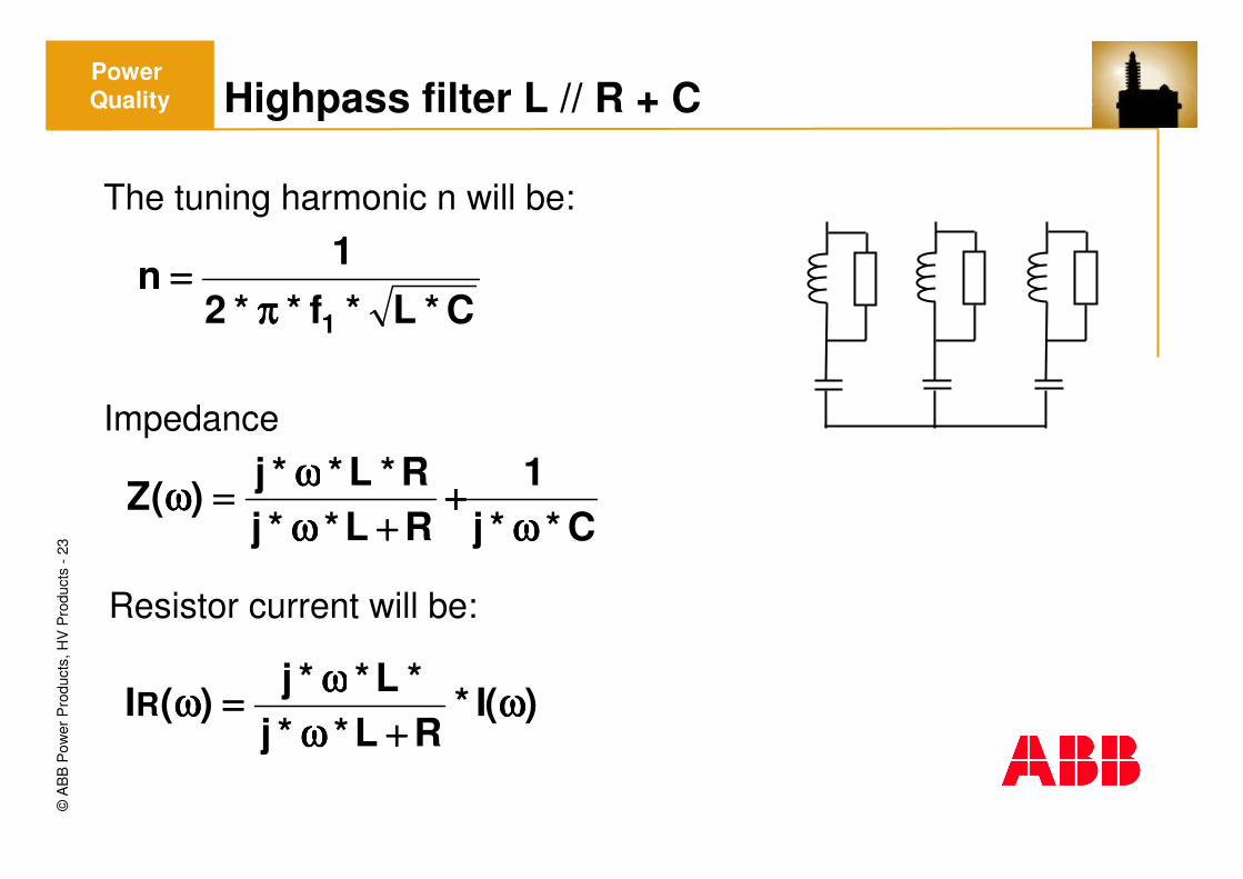
Highpass filter L // R + C
The tuning harmonic n will be:
Impedance
C*L*f**21
n1ππππ
====
C**j1
RL**jR*L**j)(Z
ωωωω++++
++++ωωωωωωωω====ωωωω
)(I*RL**j*L**j
)(IR ωωωω++++ωωωω
ωωωω====ωωωω
Resistor current will be:
Power Quality

©A
BB
Pow
er P
rodu
cts,
HV
Pro
duct
s -2
4
C-type filter (L+C2) // R + C1
� High pass plus extra capacitor
� Frequency response similar to HP-filter
� Resistor “short-circuit” for fundamental implies very low fundamental losses
� Capacitive below tuning frequency Inductive/Resistive above tuning frequency
� Damped filter suitable for low/medium tuning
� Filter quality factor q= R(fn) /�n*L at tuning frequency is controlled by the parallel resistor
� Starts to be more common in distribution networks in Europe
Power Quality

©A
BB
Pow
er P
rodu
cts,
HV
Pro
duct
s -2
5
C-type filter (L+C2) // R + C1
The tuning harmonic n will be:
Impedance
)(I*R))2C**j/(1L**j(
))2C**j/(1L**j()(IR ωωωω++++ωωωω++++ωωωω
ωωωω++++ωωωω====ωωωω
Resistor current will be:
2C1C2C*1C*L
*f**2
1n
1 ++++ππππ
====
1C**j1
)R)2C**j/(1L**j())2C**j/(1L**j(*R)(Z
ωωωω++++
++++ωωωω++++ωωωωωωωω++++ωωωω====ωωωω
R
C1
L
C2
R
C1
L
C2
R
C1
L
C2
Power Quality

©A
BB
Pow
er P
rodu
cts,
HV
Pro
duct
s -2
6
C-type filter (L+C2) // R + C1
Useful at low tuning ( n < 5 ) when damped filter are needed
Example
Qgen = 6 Mvar 11 kV± 5 %, 50 Hz ± 1,0%
Filter q-factor Tuning Losses fundamentalHighpass filter C-filter
( kW / phase ) ( kW / phase )
4 2,9 32,5 0,44 4,7 6,9 0,14 11 0,5 0,018 2,9 16,3 0,28 4,7 3,5 0,05
Power Quality
©A
BB
Pow
er P
rodu
cts,
HV
Pro
duct
s -2
7
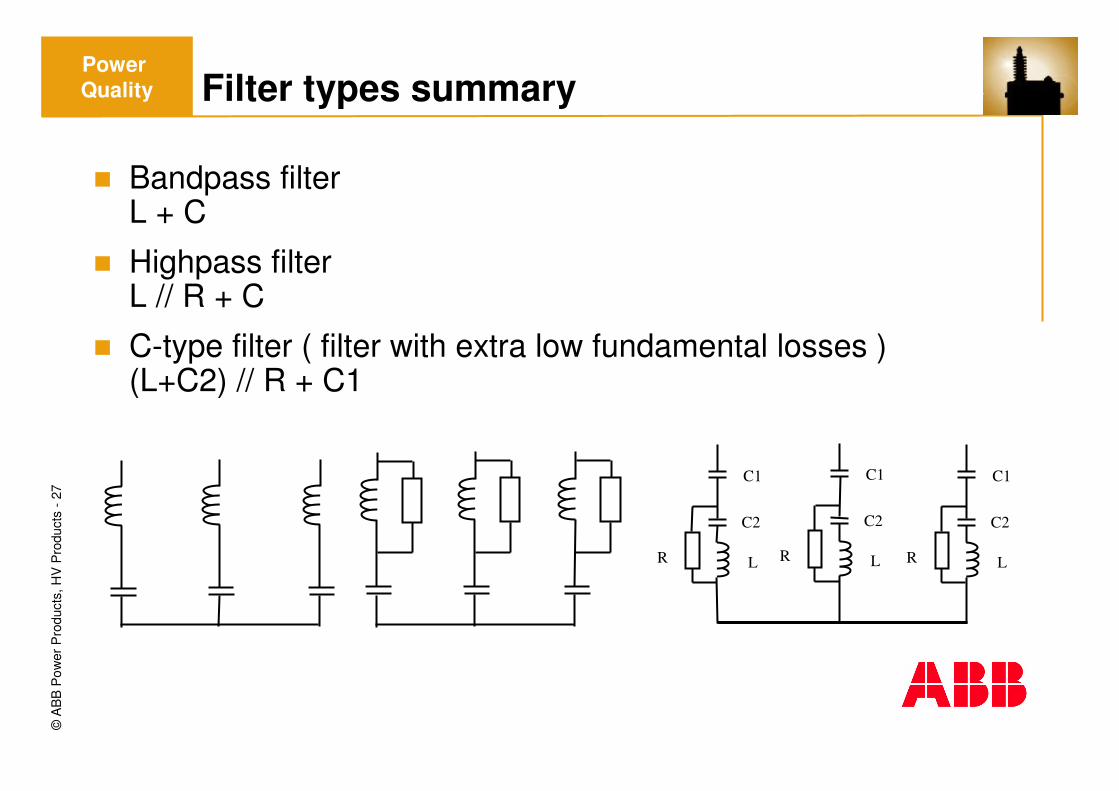
Filter types summary
� Bandpass filterL + C
� Highpass filterL // R + C
� C-type filter ( filter with extra low fundamental losses )(L+C2) // R + C1
Power Quality
R
C1
L
C2
R
C1
L
C2
R
C1
L
C2

©A
BB
Pow
er P
rodu
cts,
HV
Pro
duct
s -2
8
Static compensation / Where to compensate?
� Highest point in the system is given by the bottleneck
� Compensation location is many time a compromise
� Close to the load gives best result in terms of load reduction
� Close to the load implies more sensitive to load changesthat might increase the need for a more expensive solutions
� Close to the load might imply several compensations on same bus which might be tricky if filters are used and also more switchgear equipment
Power Quality

©A
BB
Pow
er P
rodu
cts,
HV
Pro
duct
s -2
9
Control of generation demand
� Minimum generated power is given by system calculationsPresent and target power factor together with active power
� The banks can be tailor madeCapacitance is given by generation demand and tuning
� Maximum bank size is controlled by allowed voltage rise at connectionvoltage raise at connection dU=dQ/Ssc
� Distortion demands might require more reactive power generation than power factor demand
Power Quality

©A
BB
Pow
er P
rodu
cts,
HV
Pro
duct
s -3
0
Considerations for filter capacitor bank design
� For good unbalance protection minimum 2 units in parallel
� Risk for case rapture if parallel energy is too high
� Insulation demands internal and external
� Internal fused capacitors will have less capacitance change in case of element failures
Power Quality

©A
BB
Pow
er P
rodu
cts,
HV
Pro
duct
s -3
1
Preferred Type of Capacitor FusingFusing
Bank power and voltage

©A
BB
Pow
er P
rodu
cts,
HV
Pro
duct
s -3
2
Input data for calculation
Environment DefaultLocation in/outdoorAvailable space no limitationAltitude m.a.s.l. < 1 000Ambient temperature maximum + 40 °CAmbient temperature minimum - 25 ° CMaximum daily average temperature + 30 ° CWind load if outdoor 40 m / sSeismic demands SpecifyPollution level IEC 60815 MediumStandards IEC

©A
BB
Pow
er P
rodu
cts,
HV
Pro
duct
s -3
3
Input data for calculation
Supply networkSupply voltage kV + - %Fundamental frequency Hz ± %Voltage level for guarantees kVShort-circuit power 1) min. / max. kV MVAConnection voltage for filter kVShort-circuit power at filter bus MVASingle line diagram Guarantee demands noneOther capacitances on filter bus none

©A
BB
Pow
er P
rodu
cts,
HV
Pro
duct
s -3
4
Input data for calculation
Harmonic and reactive power generationHarmonic generation Spectra.( or type of load and apparent power )Reactive power generation Mvar(load power with power factor, present and target )Harmonic generation by other sources None
MiscellaneousPower line carrier system on feeding bus None

©A
BB
Pow
er P
rodu
cts,
HV
Pro
duct
s -3
5
Grounded system (HV)
Ungrounded system (MV)
t + 6.66 mst + 3.33 ms
t
t
tt + 5 ms
RS T S T
Capacitor switching transientsPower Quality
SwitchSync principle
©A
BB
Pow
er P
rodu
cts,
HV
Pro
duct
s -3
6
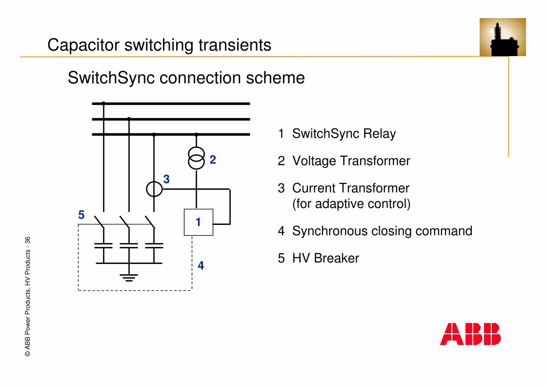
2
3
1
4
5
1 SwitchSync Relay
2 Voltage Transformer
3 Current Transformer(for adaptive control)
4 Synchronous closing command
5 HV Breaker
Capacitor switching transients
SwitchSync connection scheme

©A
BB
Pow
er P
rodu
cts,
HV
Pro
duct
s -3
7
Without SwitchSync controlled HV-BreakerClosure in an unfavourableposition.
Phase Voltage
Moment ofconnection
Time
With SwitchSync controlled HV-BreakerClosure at zero voltage
Phase Voltage
Moment ofconnection
Time
Capacitor switching transientsPower Quality
SwitchSync result

©A
BB
Pow
er P
rodu
cts,
HV
Pro
duct
s -3
8
)(
sin
c
Kcs
tL
R
s
QS
Ii
teLC
Ufi
2
2 2
=
∗∗∗∗=−
ϖ
LR
C
LN R
UU
Capacitor switching transients

©A
BB
Pow
er P
rodu
cts,
HV
Pro
duct
s -3
9
U
SwitchSync tolerance
What if the timing error is 1 ms?
� 20 ms = 360°
� 1 ms = 18°
� sin18 °= 0,309 (≈31%)
Current Transient
� Error 1 ms � factor 0.3 �peak 0.3 Is
Voltage Transient
� Max. 2 p.u.
� Error 1 ms �factor 0.3 �max. 0.6 p.u. OK!
©A
BB
Pow
er P
rodu
cts,
HV
Pro
duct
s -4
0
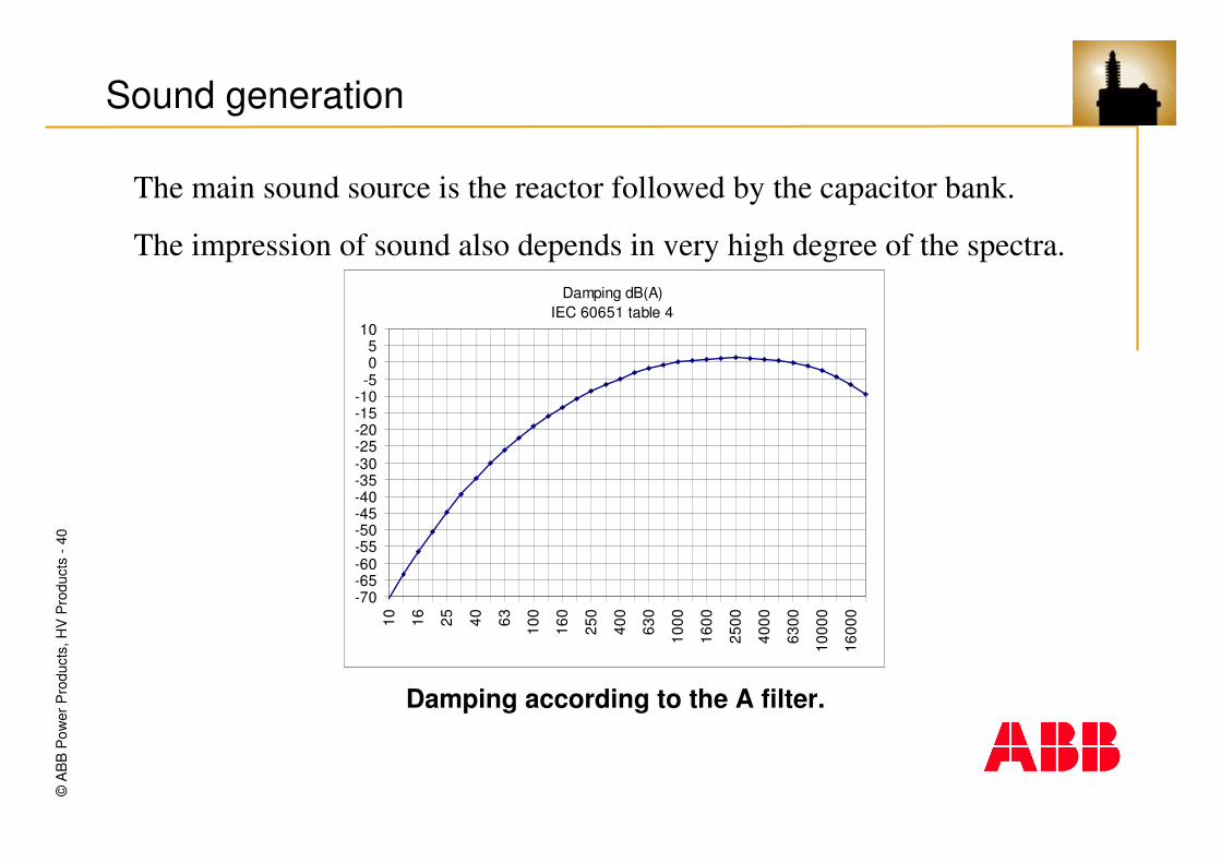
Sound generation
The main sound source is the reactor followed by the capacitor bank.
The impression of sound also depends in very high degree of the spectra.
Damping according to the A filter.
Damping dB(A)IEC 60651 table 4
-70-65-60-55-50-45-40-35-30-25-20-15-10
-505
10
10 16 25 40 63 100
160
250
400
630
1000
1600
2500
4000
6300
1000
0
1600
0

©A
BB
Pow
er P
rodu
cts,
HV
Pro
duct
s -4
1
Sound generation
Another important parameter is the propagation of sound waves
Frequencies 2 * the frequencies that be found in the spectra’s 2*fa 2*fb 2*fc 2*fdthe sum and difference of the different frequenciesfa±fb fa±fc fa±fd fb±fc fb±fd and fc±fd

©A
BB
Pow
er P
rodu
cts,
HV
Pro
duct
s -4
2
Environment and quality
ABB Capacitors
� ISO certificate according to ISO 9001 and 14000
� What is not recyclable can be burnt with limited impact on environment
� Using non toxic biodegradable oil( conventional)
� Non PCB ( All main capacitor supplier use non PCB impregnate, common demand in specifications )
Power Quality
©A
BB
Pow
er P
rodu
cts
AB
-43
-M
arch
2007
Thanks for you attention
Håkan Rörvall
Harmonic filters and applications