Embed Size (px)
Citation preview
Infoblox Installation GuideFor the Trinzic Reporting 2000 Appliance
Contents
Introduction . . . . . . . . . . . . . . . . . . . . . . . . . . . . . . . . . . . . . . . . . . . . . . . . . . . . . . . . . . . . . . . . . . 3
Product Overview . . . . . . . . . . . . . . . . . . . . . . . . . . . . . . . . . . . . . . . . . . . . . . . . . . . . . . . . . . . . . . . . . . . . . . . . . . . . . . .3
Hardware Components. . . . . . . . . . . . . . . . . . . . . . . . . . . . . . . . . . . . . . . . . . . . . . . . . . . . . . . . . . . . . . . . . . . . . . . . . . .4
System, Environmental, and Power Specifications . . . . . . . . . . . . . . . . . . . . . . . . . . . . . . . . . . . . . . . . . . . . . . . . . . . .9
Installing an Appliance . . . . . . . . . . . . . . . . . . . . . . . . . . . . . . . . . . . . . . . . . . . . . . . . . . . . . . . . 11
Rack Mounting . . . . . . . . . . . . . . . . . . . . . . . . . . . . . . . . . . . . . . . . . . . . . . . . . . . . . . . . . . . . . . . . . . . . . . . . . . . . . . . 11
Installing the Backup Battery Unit. . . . . . . . . . . . . . . . . . . . . . . . . . . . . . . . . . . . . . . . . . . . . . . . . . . . . . . . . . . . . . . . 13
Powering the Appliance . . . . . . . . . . . . . . . . . . . . . . . . . . . . . . . . . . . . . . . . . . . . . . . . . . . . . . . . . . . . . . . . . . . . . . . . 13
Cabling the Appliance to a Network . . . . . . . . . . . . . . . . . . . . . . . . . . . . . . . . . . . . . . . . . . . . . . . . . . . . . . . . . . . . . . 14
Changing Power Supplies . . . . . . . . . . . . . . . . . . . . . . . . . . . . . . . . . . . . . . . . . . . . . . . . . . . . . . . . . . . . . . . . . . . . . . 15
Changing Fan Modules. . . . . . . . . . . . . . . . . . . . . . . . . . . . . . . . . . . . . . . . . . . . . . . . . . . . . . . . . . . . . . . . . . . . . . . . . 16
Changing Disk Drives . . . . . . . . . . . . . . . . . . . . . . . . . . . . . . . . . . . . . . . . . . . . . . . . . . . . . . . . . . . . . . . . . . . . . . . . . . 17
Changing the Backup Battery Unit . . . . . . . . . . . . . . . . . . . . . . . . . . . . . . . . . . . . . . . . . . . . . . . . . . . . . . . . . . . . . . . 20
Accessing the Appliance . . . . . . . . . . . . . . . . . . . . . . . . . . . . . . . . . . . . . . . . . . . . . . . . . . . . . . . 21
Connecting to the Appliance . . . . . . . . . . . . . . . . . . . . . . . . . . . . . . . . . . . . . . . . . . . . . . . . . . . . . . . . . . . . . . . . . . . . 22
Specifying Appliance Settings. . . . . . . . . . . . . . . . . . . . . . . . . . . . . . . . . . . . . . . . . . . . . . . . . . . . . . . . . . . . . . . . . . . 23
Infoblox GUI . . . . . . . . . . . . . . . . . . . . . . . . . . . . . . . . . . . . . . . . . . . . . . . . . . . . . . . . . . . . . . . . . . . . . . . . . . . . . . . . . 25
Infoblox CLI . . . . . . . . . . . . . . . . . . . . . . . . . . . . . . . . . . . . . . . . . . . . . . . . . . . . . . . . . . . . . . . . . . . . . . . . . . . . . . . . . . 26
Managing the Disk Subsystem . . . . . . . . . . . . . . . . . . . . . . . . . . . . . . . . . . . . . . . . . . . . . . . . . . . . . . . . . . . . . . . . . . 27
Copyright Statements
© 2011-2012, Infoblox Inc.— All rights reserved.The contents of this document may not be copied or duplicated in any form, in whole or in part, without the prior written permission of Infoblox, Inc.
The information in this document is subject to change without notice. Infoblox, Inc. shall not be liable for any damages resulting from technical errors or omissions which may be present in this document, or from use of this document.
This document is an unpublished work protected by the United States copyright laws and is proprietary to Infoblox, Inc. Disclosure, copying, reproduction, merger, translation, modification, enhancement, or use of this document by anyone other than authorized employees, authorized users, or licensees of Infoblox, Inc. without the prior written consent of Infoblox, Inc. is prohibited.
For Open Source Copyright information, see Open Source Copyright and License Statements in the Infoblox NIOS Administrator Guide.
1
Contents
Trademark Statements
Infoblox, the Infoblox logo, Grid, NIOS, bloxTools, NetMRI and PortIQ are trademarks or registered trademarks of
Infoblox Inc.
All other trademarked names used herein are the properties of their respective owners and are used for identification purposes only.
Warranty Information
Your purchase includes a 90-day software warranty and a one year limited warranty on the Infoblox appliance, plus an Infoblox Warranty Support Plan and Technical Support. For more information about Infoblox Warranty information, refer to the Infoblox website, or contact Infoblox Technical Support.
Company Information
Infoblox is located at:4750 Patrick Henry DriveSanta Clara, CA 95054-1851, USA
Web: www.infoblox.comwww.infoblox.com/support
Phone: 408.625.4200 Toll Free: 888.463.6259 Outside North America: +1.408.716.4300 Fax: 408.625.4201
Product Information
Hardware Models: Infoblox-250-A, 550-A, -1050-A, -1550-A, 1552-A, -1852-A, 2000-A, Trinzic 810, Trinzic 820,
Trinzic 1410, Trinzic 1420, and Trinzic 4010
Document Number: TBD, Rev. A
Document Updated: December 21, 2011
2 Infoblox Installation Guide
Introduction
This guide provides an overview of the Trinzic Reporting 2000 network appliance, and explains how to install and
configure the system. You can add the Trinzic Reporting 2000 appliance as a member to the Infoblox Grid and
configure it as a dedicated logging and reporting appliance. Note that you cannot configure the reporting appliance
as an HA pair.
The Infoblox reporting solution automates the collection, analysis, and presentation of core network service data
that assists you in planning and mitigating network outage risks, so you can manage your networks more efficiently.
For more information about the Infoblox reporting solution, refer to the Infoblox NIOS Administrator Guide.
Product Overview
The Trinzic Reporting 2000 is a high performance network appliance that collects data from Infoblox Grid members,
stores the data in the reporting database, and generates reports that provide statistical data about IPAM, DNS, and
DHCP activities and performance. It can receive up to 10 GB of data each day. You configure and manage the Trinzic
Reporting 2000 and view reports through an easy-to-use Infoblox GUI that works seamlessly in Windows, Linux, and
Mac environments using standard web browsers. For more information about the Infoblox GUI, refer to the Infoblox
NIOS Administrator Guide.
The Trinzic Reporting 2000 appliance comprises hot-swappable power supplies, replaceable hard disk drives, and
optional network interfaces. The Trinzic Reporting 2000 is a Class A digital appliance per FCC regulations, and RoHS
and it is WEEE compliant.
For the Trinzic Reporting 2000 Appliance 3
Introduction
Hardware Components
The Trinzic Reporting 2000 is a 3-U platform that you can easily mount in a standard equipment rack using the
mounting brackets and bolts that ship with each appliance. The front panel components include the LCD (liquid
crystal display) panel and navigation buttons, communication ports, hard disk drives, and indicator lights. The back
panel components include power connectors and switches, fans, air vents, and a backup battery unit.
Front Panel
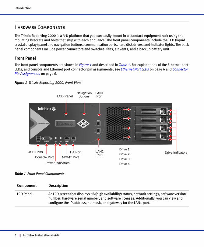
The front panel components are shown in Figure 1 and described in Table 1. For explanations of the Ethernet port
LEDs, and console and Ethernet port connector pin assignments, see Ethernet Port LEDs on page 6 and Connector
Pin Assignments on page 6.
Figure 1 Trinzic Reporting 2000, Front View
Table 1 Front Panel Components
Component Description
LCD Panel An LCD screen that displays HA (high availability) status, network settings, software version
number, hardware serial number, and software licenses. Additionally, you can view and
configure the IP address, netmask, and gateway for the LAN1 port.
USB Ports
MGMT PortConsole Port
Power Indicators
HA Port LAN2 Port
Drive Indicators
LCD PanelNavigation
ButtonsLAN1 Port
Drive 1
Drive 2
Drive 3
Drive 4
4 Infoblox Installation Guide
Hardware Components
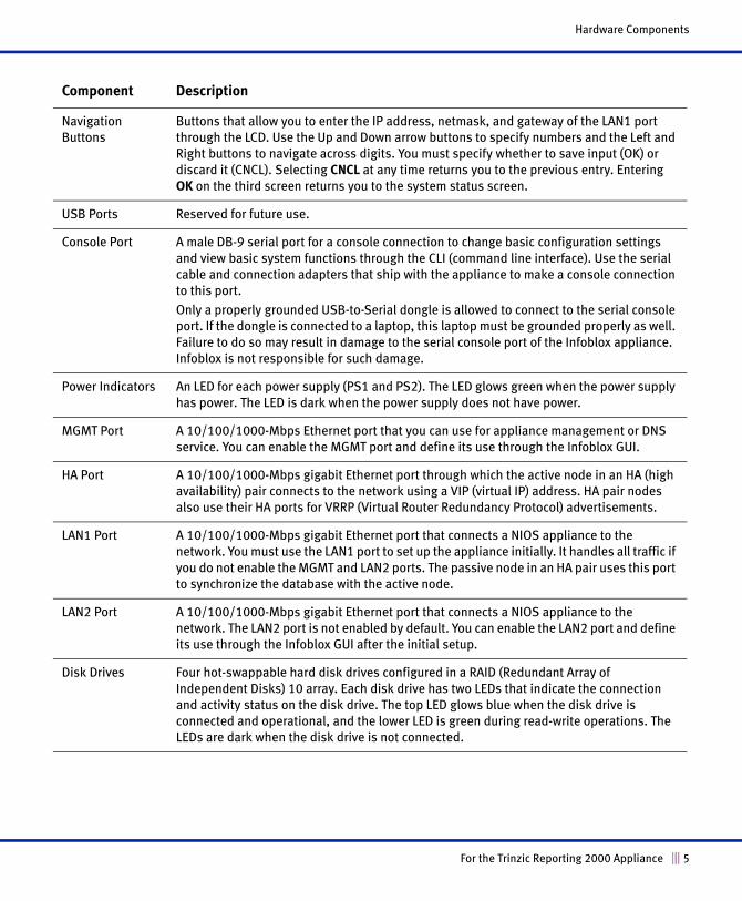
Navigation Buttons
Buttons that allow you to enter the IP address, netmask, and gateway of the LAN1 port
through the LCD. Use the Up and Down arrow buttons to specify numbers and the Left and
Right buttons to navigate across digits. You must specify whether to save input (OK) or
discard it (CNCL). Selecting CNCL at any time returns you to the previous entry. Entering
OK on the third screen returns you to the system status screen.
USB Ports Reserved for future use.
Console Port A male DB-9 serial port for a console connection to change basic configuration settings
and view basic system functions through the CLI (command line interface). Use the serial
cable and connection adapters that ship with the appliance to make a console connection
to this port.
Only a properly grounded USB-to-Serial dongle is allowed to connect to the serial console
port. If the dongle is connected to a laptop, this laptop must be grounded properly as well.
Failure to do so may result in damage to the serial console port of the Infoblox appliance.
Infoblox is not responsible for such damage.
Power Indicators An LED for each power supply (PS1 and PS2). The LED glows green when the power supply
has power. The LED is dark when the power supply does not have power.
MGMT Port A 10/100/1000-Mbps Ethernet port that you can use for appliance management or DNS
service. You can enable the MGMT port and define its use through the Infoblox GUI.
HA Port A 10/100/1000-Mbps gigabit Ethernet port through which the active node in an HA (high
availability) pair connects to the network using a VIP (virtual IP) address. HA pair nodes
also use their HA ports for VRRP (Virtual Router Redundancy Protocol) advertisements.
LAN1 Port A 10/100/1000-Mbps gigabit Ethernet port that connects a NIOS appliance to the
network. You must use the LAN1 port to set up the appliance initially. It handles all traffic if
you do not enable the MGMT and LAN2 ports. The passive node in an HA pair uses this port
to synchronize the database with the active node.
LAN2 Port A 10/100/1000-Mbps gigabit Ethernet port that connects a NIOS appliance to the
network. The LAN2 port is not enabled by default. You can enable the LAN2 port and define
its use through the Infoblox GUI after the initial setup.
Disk Drives Four hot-swappable hard disk drives configured in a RAID (Redundant Array of
Independent Disks) 10 array. Each disk drive has two LEDs that indicate the connection
and activity status on the disk drive. The top LED glows blue when the disk drive is
connected and operational, and the lower LED is green during read-write operations. The
LEDs are dark when the disk drive is not connected.
Component Description
For the Trinzic Reporting 2000 Appliance 5
Introduction
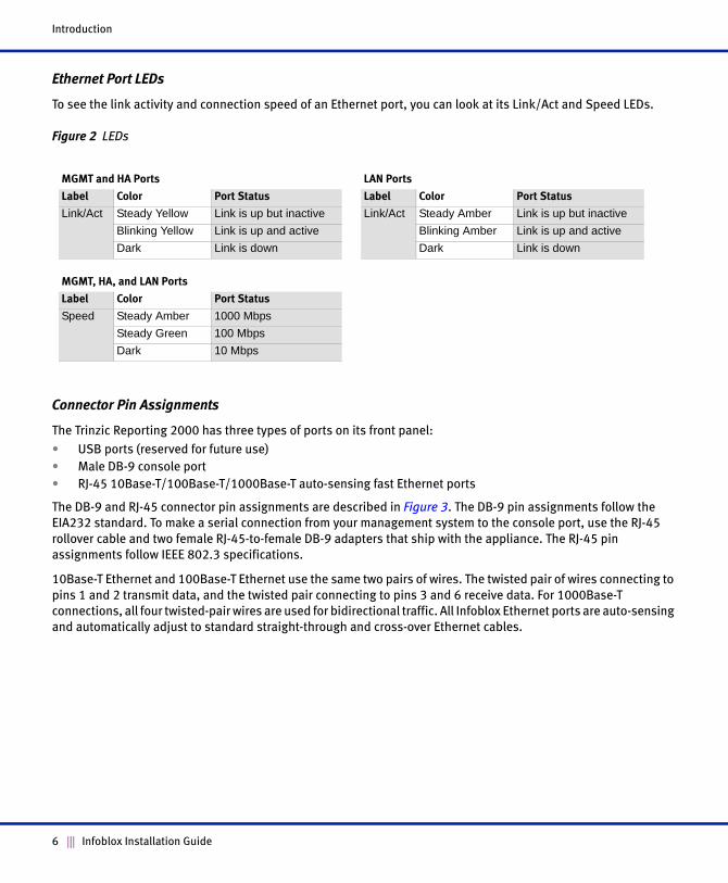
Ethernet Port LEDs
To see the link activity and connection speed of an Ethernet port, you can look at its Link/Act and Speed LEDs.
Figure 2 LEDs
Connector Pin Assignments
The Trinzic Reporting 2000 has three types of ports on its front panel:
• USB ports (reserved for future use)
• Male DB-9 console port
• RJ-45 10Base-T/100Base-T/1000Base-T auto-sensing fast Ethernet ports
The DB-9 and RJ-45 connector pin assignments are described in Figure 3. The DB-9 pin assignments follow the
EIA232 standard. To make a serial connection from your management system to the console port, use the RJ-45
rollover cable and two female RJ-45-to-female DB-9 adapters that ship with the appliance. The RJ-45 pin
assignments follow IEEE 802.3 specifications.
10Base-T Ethernet and 100Base-T Ethernet use the same two pairs of wires. The twisted pair of wires connecting to
pins 1 and 2 transmit data, and the twisted pair connecting to pins 3 and 6 receive data. For 1000Base-T
connections, all four twisted-pair wires are used for bidirectional traffic. All Infoblox Ethernet ports are auto-sensing
and automatically adjust to standard straight-through and cross-over Ethernet cables.
MGMT and HA Ports LAN Ports
Label Color Port Status Label Color Port Status
Link/Act Steady Yellow Link is up but inactive Link/Act Steady Amber Link is up but inactive
Blinking Yellow Link is up and active Blinking Amber Link is up and active
Dark Link is down Dark Link is down
MGMT, HA, and LAN Ports
Label Color Port Status
Speed Steady Amber 1000 Mbps
Steady Green 100 Mbps
Dark 10 Mbps
6 Infoblox Installation Guide
Hardware Components
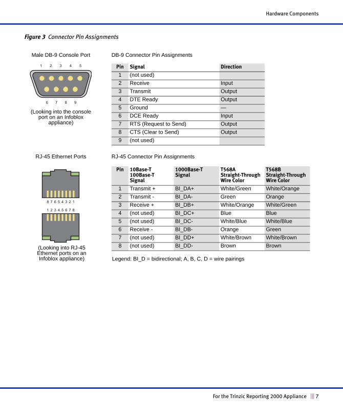
Figure 3 Connector Pin Assignments
21 3 4 5
6 7 8 9
21 3 4 65 7 8
78 6 5 34 2 1
DB-9 Connector Pin Assignments
RJ-45 Connector Pin Assignments
Pin 10Base-T 100Base-TSignal
1000Base-T Signal
T568AStraight-Through Wire Color
T568BStraight-Through Wire Color
1 Transmit + BI_DA+ White/Green White/Orange
2 Transmit - BI_DA- Green Orange
3 Receive + BI_DB+ White/Orange White/Green
4 (not used) BI_DC+ Blue Blue
5 (not used) BI_DC- White/Blue White/Blue
6 Receive - BI_DB- Orange Green
7 (not used) BI_DD+ White/Brown White/Brown
8 (not used) BI_DD- Brown Brown
Male DB-9 Console Port
RJ-45 Ethernet Ports
Pin Signal Direction
1 (not used)
2 Receive Input
3 Transmit Output
4 DTE Ready Output
5 Ground —
6 DCE Ready Input
7 RTS (Request to Send) Output
8 CTS (Clear to Send) Output
9 (not used)
Legend: BI_D = bidirectional; A, B, C, D = wire pairings
(Looking into the console port on an Infoblox
appliance)
(Looking into RJ-45 Ethernet ports on an Infoblox appliance)
For the Trinzic Reporting 2000 Appliance 7
Introduction
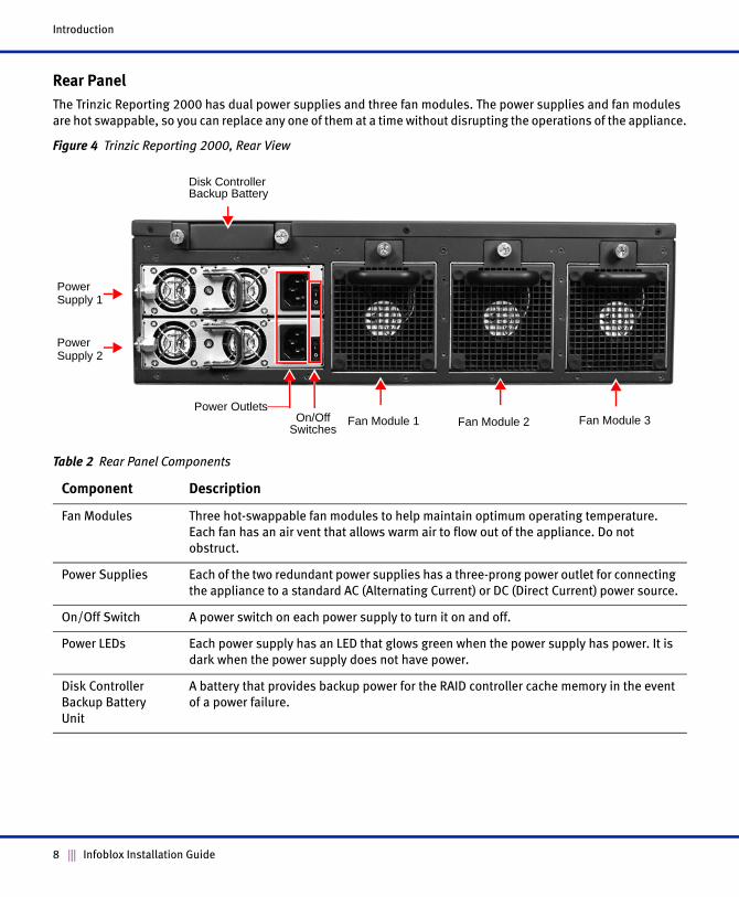
Rear Panel
The Trinzic Reporting 2000 has dual power supplies and three fan modules. The power supplies and fan modules
are hot swappable, so you can replace any one of them at a time without disrupting the operations of the appliance.
Figure 4 Trinzic Reporting 2000, Rear View
Table 2 Rear Panel Components
Component Description
Fan Modules Three hot-swappable fan modules to help maintain optimum operating temperature.
Each fan has an air vent that allows warm air to flow out of the appliance. Do not
obstruct.
Power Supplies Each of the two redundant power supplies has a three-prong power outlet for connecting
the appliance to a standard AC (Alternating Current) or DC (Direct Current) power source.
On/Off Switch A power switch on each power supply to turn it on and off.
Power LEDs Each power supply has an LED that glows green when the power supply has power. It is
dark when the power supply does not have power.
Disk Controller
Backup Battery
Unit
A battery that provides backup power for the RAID controller cache memory in the event
of a power failure.
Power OutletsFan Module 1On/Off
Switches
Power Supply 1
Disk Controller Backup Battery
Power Supply 2
Fan Module 2 Fan Module 3
8 Infoblox Installation Guide
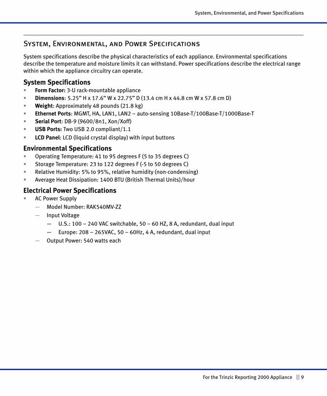
System, Environmental, and Power Specifications
System, Environmental, and Power Specifications
System specifications describe the physical characteristics of each appliance. Environmental specifications
describe the temperature and moisture limits it can withstand. Power specifications describe the electrical range
within which the appliance circuitry can operate.
System Specifications • Form Factor: 3-U rack-mountable appliance
• Dimensions: 5.25” H x 17.6” W x 22.75” D (13.4 cm H x 44.8 cm W x 57.8 cm D)
• Weight: Approximately 48 pounds (21.8 kg)
• Ethernet Ports: MGMT, HA, LAN1, LAN2 – auto-sensing 10Base-T/100Base-T/1000Base-T
• Serial Port: DB-9 (9600/8n1, Xon/Xoff)
• USB Ports: Two USB 2.0 compliant/1.1
• LCD Panel: LCD (liquid crystal display) with input buttons
Environmental Specifications• Operating Temperature: 41 to 95 degrees F (5 to 35 degrees C)
• Storage Temperature: 23 to 122 degrees F (-5 to 50 degrees C)
• Relative Humidity: 5% to 95%, relative humidity (non-condensing)
• Average Heat Dissipation: 1400 BTU (British Thermal Units)/hour
Electrical Power Specifications• AC Power Supply
— Model Number: RAK540MV-ZZ
— Input Voltage
— U.S.: 100 – 240 VAC switchable, 50 – 60 HZ, 8 A, redundant, dual input
— Europe: 208 – 265VAC, 50 – 60Hz, 4 A, redundant, dual input
— Output Power: 540 watts each
For the Trinzic Reporting 2000 Appliance 9
Introduction
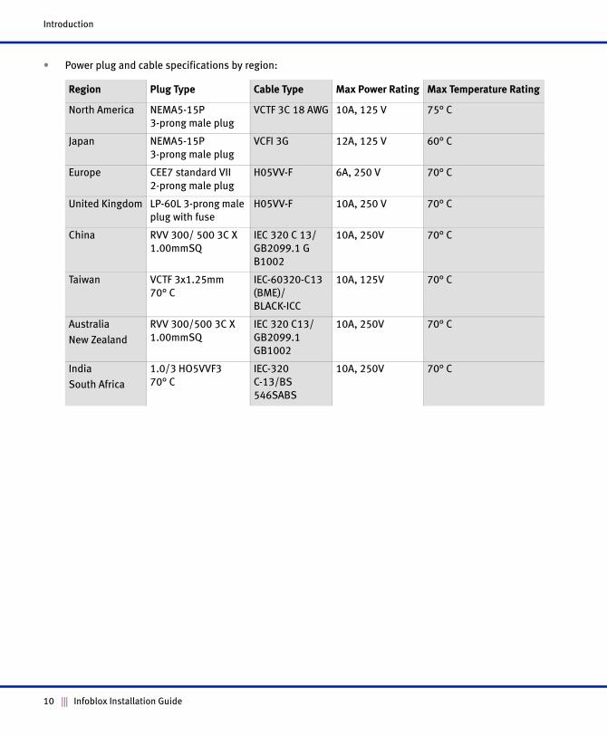
• Power plug and cable specifications by region:
Region Plug Type Cable Type Max Power Rating Max Temperature Rating
North America NEMA5-15P 3-prong male plug
VCTF 3C 18 AWG 10A, 125 V 75° C
Japan NEMA5-15P 3-prong male plug
VCFI 3G 12A, 125 V 60° C
Europe CEE7 standard VII
2-prong male plug
H05VV-F 6A, 250 V 70° C
United Kingdom LP-60L 3-prong male
plug with fuse
H05VV-F 10A, 250 V 70° C
China RVV 300/ 500 3C X
1.00mmSQ
IEC 320 C 13/
GB2099.1 G
B1002
10A, 250V 70° C
Taiwan VCTF 3x1.25mm 70° C
IEC-60320-C13
(BME)/
BLACK-ICC
10A, 125V 70° C
Australia
New Zealand
RVV 300/500 3C X
1.00mmSQ
IEC 320 C13/
GB2099.1
GB1002
10A, 250V 70° C
India
South Africa
1.0/3 HO5VVF3 70° C
IEC-320
C-13/BS
546SABS
10A, 250V 70° C
10 Infoblox Installation Guide
Installing an Appliance
Follow these instructions to rack mount the appliance, install the backup battery unit, connect the appliance to a
power source, and cable it to a network. However, before proceeding, review the Infoblox Safety Guide and follow
the necessary precautions.
Rack Mounting
The Trinzic Reporting 2000 mounts into a standard 19” (48 cm) equipment rack. The appliance ships with mounting
brackets at the front, and an accessory kit that contains a pair of rear slide brackets and mounting hardware. To
mount the appliance to an equipment rack, you will also need a screwdriver with a cross-headed tip. There are two
ways to rack mount the Trinzic Reporting 2000:
• Front and rear mount
• Mid-mount
Front and Rear Mount
To mount the appliance to an equipment rack and secure it at the front and rear rack posts:
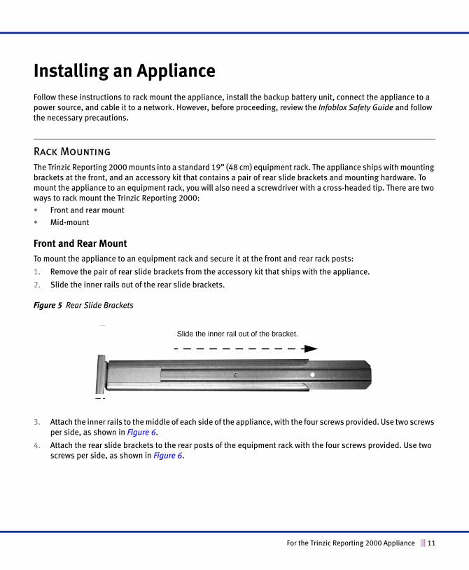
1. Remove the pair of rear slide brackets from the accessory kit that ships with the appliance.
2. Slide the inner rails out of the rear slide brackets.
Figure 5 Rear Slide Brackets
3. Attach the inner rails to the middle of each side of the appliance, with the four screws provided. Use two screws
per side, as shown in Figure 6.
4. Attach the rear slide brackets to the rear posts of the equipment rack with the four screws provided. Use two
screws per side, as shown in Figure 6.
Slide the inner rail out of the bracket.
For the Trinzic Reporting 2000 Appliance 11
Installing an Appliance
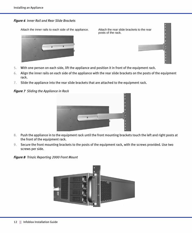
Figure 6 Inner Rail and Rear Slide Brackets
5. With one person on each side, lift the appliance and position it in front of the equipment rack.
6. Align the inner rails on each side of the appliance with the rear slide brackets on the posts of the equipment
rack.
7. Slide the appliance into the rear slide brackets that are attached to the equipment rack.
Figure 7 Sliding the Appliance in Rack
8. Push the appliance in to the equipment rack until the front mounting brackets touch the left and right posts at
the front of the equipment rack.
9. Secure the front mounting brackets to the posts of the equipment rack, with the screws provided. Use two
screws per side.
Figure 8 Trinzic Reporting 2000 Front Mount
Attach the inner rails to each side of the appliance. Attach the rear slide brackets to the rear posts of the rack.
12 Infoblox Installation Guide
Installing the Backup Battery Unit
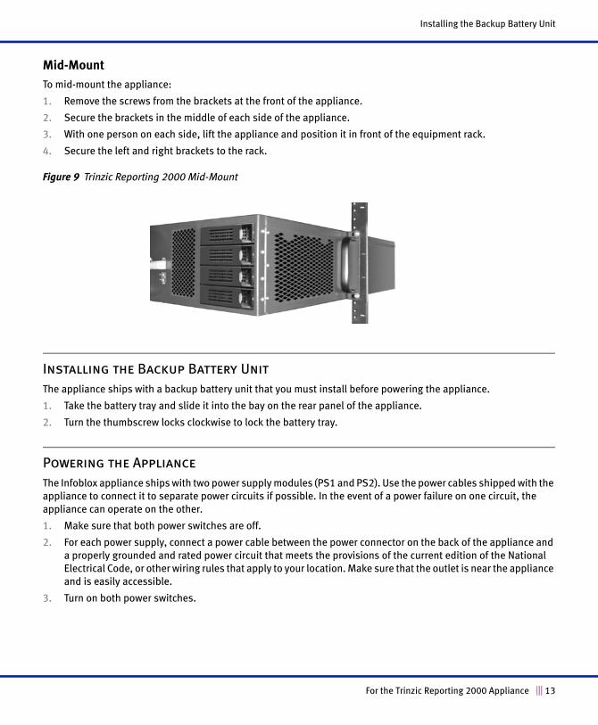
Mid-Mount
To mid-mount the appliance:
1. Remove the screws from the brackets at the front of the appliance.
2. Secure the brackets in the middle of each side of the appliance.
3. With one person on each side, lift the appliance and position it in front of the equipment rack.
4. Secure the left and right brackets to the rack.
Figure 9 Trinzic Reporting 2000 Mid-Mount
Installing the Backup Battery Unit
The appliance ships with a backup battery unit that you must install before powering the appliance.
1. Take the battery tray and slide it into the bay on the rear panel of the appliance.
2. Turn the thumbscrew locks clockwise to lock the battery tray.
Powering the Appliance
The Infoblox appliance ships with two power supply modules (PS1 and PS2). Use the power cables shipped with the
appliance to connect it to separate power circuits if possible. In the event of a power failure on one circuit, the
appliance can operate on the other.
1. Make sure that both power switches are off.
2. For each power supply, connect a power cable between the power connector on the back of the appliance and
a properly grounded and rated power circuit that meets the provisions of the current edition of the National
Electrical Code, or other wiring rules that apply to your location. Make sure that the outlet is near the appliance
and is easily accessible.
3. Turn on both power switches.
For the Trinzic Reporting 2000 Appliance 13
Installing an Appliance
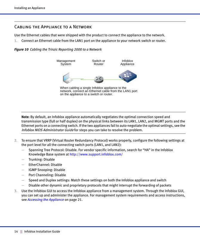
Cabling the Appliance to a Network
Use the Ethernet cables that were shipped with the product to connect the appliance to the network.
1. Connect an Ethernet cable from the LAN1 port on the appliance to your network switch or router.
Figure 10 Cabling the Trinzic Reporting 2000 to a Network
Note: By default, an Infoblox appliance automatically negotiates the optimal connection speed and
transmission type (full or half duplex) on the physical links between its LAN1, LAN2, and MGMT ports and the
Ethernet ports on a connecting switch. If the two appliances fail to auto-negotiate the optimal settings, see the
Infoblox NIOS Administrator Guide for steps you can take to resolve the problem.
2. To ensure that VRRP (Virtual Router Redundancy Protocol) works properly, configure the following settings at
the port level for all the connecting switch ports (LAN1, and LAN2):
— Spanning Tree Protocol: Disable. For vendor specific information, search for “HA” in the Infoblox
Knowledge Base system at http://www.support.infoblox.com/
— Trunking: Disable
— EtherChannel: Disable
— IGMP Snooping: Disable
— Port Channeling: Disable
— Speed and Duplex settings: Match these settings on both the Infoblox appliance and switch
— Disable other dynamic and proprietary protocols that might interrupt the forwarding of packets
3. Use the Infoblox GUI to access the Infoblox appliance from a management system. Through the Infoblox GUI,
you can set up and administer the appliance. For management system requirements and access instructions,
see Accessing the Appliance on page 21.
Switch or Router
When cabling a single Infoblox appliance to the network, connect an Ethernet cable from the LAN1 port on the appliance to a switch or router.
Infoblox Appliance
Management System
14 Infoblox Installation Guide
Changing Power Supplies
Changing Power Supplies
The Trinzic Reporting 2000 ships with two redundant, auto-switching AC power supplies. The power supplies are
“hot-swappable”, so you can remove or replace one power supply without interrupting appliance operation and
network services.
When the Trinzic Reporting 2000 contains two functioning power supplies, they share the power load equally. If one
power supply fails, the other assumes the full load automatically and the appliance sends a system alarm. Although
the Trinzic Reporting 2000 can run with only one power supply, it is advisable to install both power supplies that
were shipped with the appliance. This practice minimizes the chance of system failure due to an individual power
supply failure.
Each power supply weighs about three pounds (1.36 kg). The faceplate of the power supply contains a power LED
and a power switch. Each power supply links to a dedicated male power outlet.
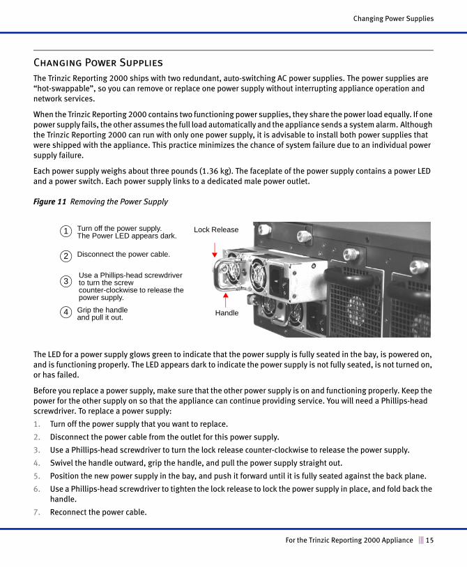
Figure 11 Removing the Power Supply
The LED for a power supply glows green to indicate that the power supply is fully seated in the bay, is powered on,
and is functioning properly. The LED appears dark to indicate the power supply is not fully seated, is not turned on,
or has failed.
Before you replace a power supply, make sure that the other power supply is on and functioning properly. Keep the
power for the other supply on so that the appliance can continue providing service. You will need a Phillips-head
screwdriver. To replace a power supply:
1. Turn off the power supply that you want to replace.
2. Disconnect the power cable from the outlet for this power supply.
3. Use a Phillips-head screwdriver to turn the lock release counter-clockwise to release the power supply.
4. Swivel the handle outward, grip the handle, and pull the power supply straight out.
5. Position the new power supply in the bay, and push it forward until it is fully seated against the back plane.
6. Use a Phillips-head screwdriver to tighten the lock release to lock the power supply in place, and fold back the
handle.
7. Reconnect the power cable.
Grip the handle and pull it out.
Use a Phillips-head screwdriver to turn the screw counter-clockwise to release the power supply.
Turn off the power supply.The Power LED appears dark.
Disconnect the power cable.
Lock Release
Handle
1
2
3
4
For the Trinzic Reporting 2000 Appliance 15
Installing an Appliance
8. Turn on the power supply. If it is fully seated, powered on, and operating properly, the LED glows green.
Changing Fan Modules
The Trinzic Reporting 2000 ships with three hot-swappable fan modules, so you can replace a fan module without
interrupting appliance operations. Each fan has an air vent that allows warm air to flow out of the appliance.
If a fan stops operating due to removal or a failure, the appliance continues to run, but generates an SNMP trap. You
can also monitor the status of the fan modules by logging in to the Infoblox GUI, and from the Grid Perspective,
select the appliance and click View -> Status.
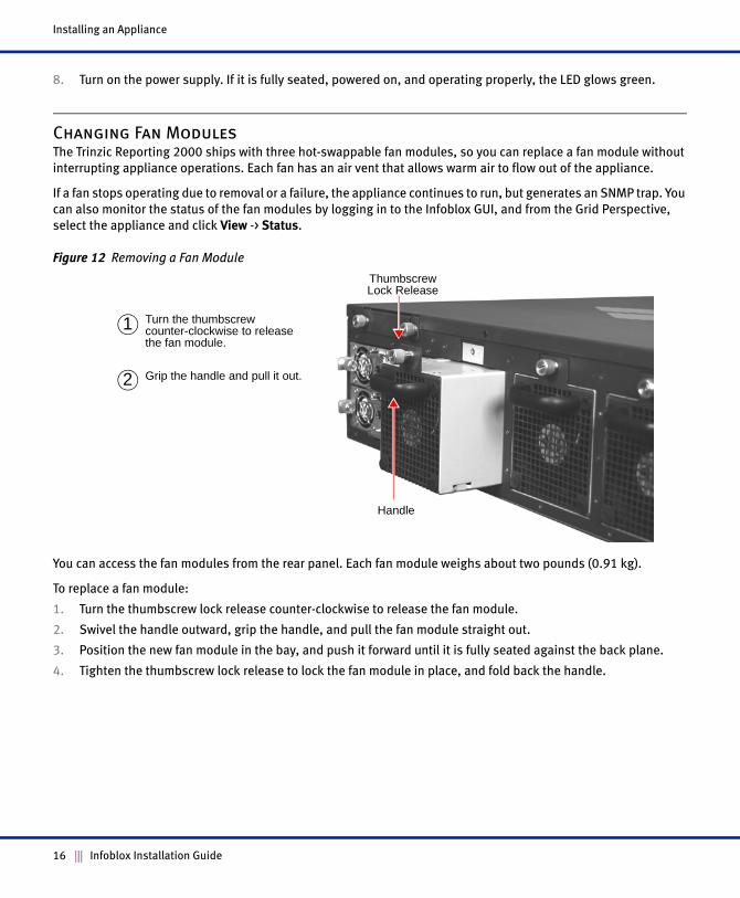
Figure 12 Removing a Fan Module
You can access the fan modules from the rear panel. Each fan module weighs about two pounds (0.91 kg).
To replace a fan module:
1. Turn the thumbscrew lock release counter-clockwise to release the fan module.
2. Swivel the handle outward, grip the handle, and pull the fan module straight out.
3. Position the new fan module in the bay, and push it forward until it is fully seated against the back plane.
4. Tighten the thumbscrew lock release to lock the fan module in place, and fold back the handle.
Grip the handle and pull it out.
Turn the thumbscrew counter-clockwise to release the fan module.
1
2
Thumbscrew Lock Release
Handle
16 Infoblox Installation Guide
Changing Disk Drives
Changing Disk Drives
The Trinzic Reporting 2000 ships with four hot-swappable hard disk drives configured in a RAID (Redundant Array
of Independent Disks) 10 array. It was designed to provide continuous operation in the event of a failed disk.
Hot-swapping a disk drive is a simple process that does not require issuing commands or a GUI operation.
When you replace a failed disk, you must replace it with an Infoblox supplied disk. To ensure that you receive the
correct replacement disk, report the disk type or part number of the failed disk. The appliance displays the disk type
in the Detailed Status panel of the Infoblox GUI, and the Infoblox part number is printed on the disk. Installing disks
that are not qualified and shipped from Infoblox could cause failures in the appliance.
You can access the disk drives from the front of the appliance. Each disk drive weighs about 2 pounds (.90 kg).
You can remove or replace a defective drive without interrupting appliance operations or network services. To
remove a disk drive:
1. Identify and verify the failed drive through the Infoblox GUI, the front panel LCD, or the CLI.
2. If the activity light is green or blinking green, make sure that you have identified the correct drive. There are
conditions where a drive could be in the process of failing and still be green.
Caution: Never remove a correctly functioning drive. If a disk drive fails, remove the failed disk only. NEVER remove
two or more disks at once. Removing more than one disk at a time can cause a complete failure of the appliance and
require an RMA (Return Material Authorization). All replacement drives must complete the rebuilding process before
you can remove another drive. Log in to the Infoblox GUI and check the status of the disk drives. For additional
information about managing and monitoring the disk drives, see Managing the Disk Subsystem on page 27.
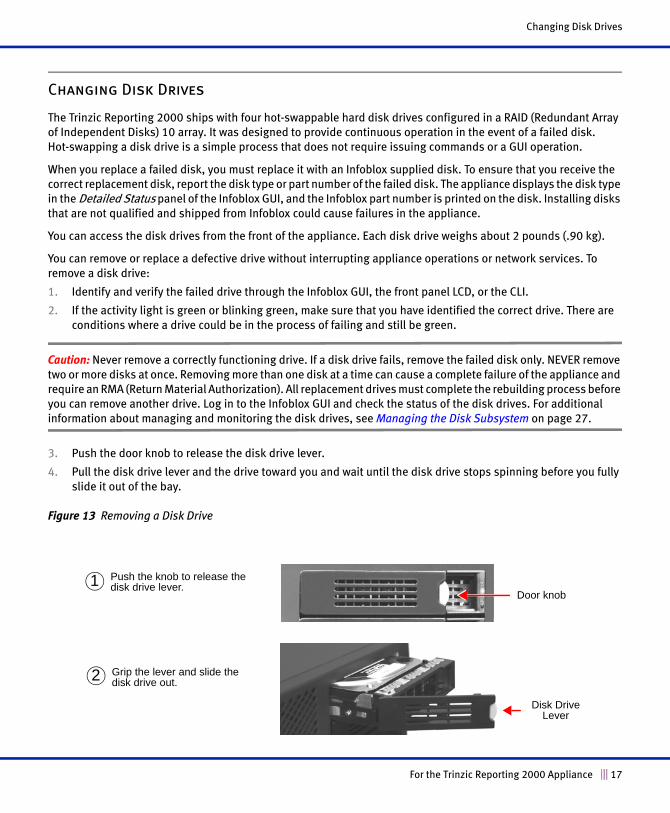
3. Push the door knob to release the disk drive lever.
4. Pull the disk drive lever and the drive toward you and wait until the disk drive stops spinning before you fully
slide it out of the bay.
Figure 13 Removing a Disk Drive
Push the knob to release the disk drive lever.1
Disk Drive Lever
Grip the lever and slide the disk drive out.2
Door knob
For the Trinzic Reporting 2000 Appliance 17
Installing an Appliance
To install a replacement drive, follow this procedure:
1. Replacement drives are shipped as a complete unit, ready to insert into the appliance. There is no preparation
required.
2. Push the door knob to release the disk drive lever.
3. Pull the disk drive lever and the drive toward you and wait until the disk drive stops spinning before you fully
slide it out of the bay.
4. Position the new disk drive in the bay.
5. Push the disk drive forward until it is fully seated against the back plane.
As you push the drive forward, the lever slides forward and starts to close as well.
6. Push the lever down to lock the disk drive in place.
The LED next to the disk drive lights up.
7. The disk drive automatically goes into rebuild mode.
Disk Array Guidelines
Infoblox has designed the disk array to be completely self managed. There are no maintenance procedures required
for a normally functioning disk array. Mishandling the disk array can cause an unrecoverable error and result in a
failed appliance. Infoblox highly recommends that you observe the following guidelines:
• Remove only one disk at a time. Do not remove two or more disks from the appliance at the same time.
Removing two or more disks at the same time might result in an appliance failure and require an RMA of the
appliance. This rule applies to both powered and powered down appliances.
• If the status of the array is degraded, remove the failed or failing disk drive only. Do not remove an optimally
functioning drive.
• If your acceptance procedure requires a test of the RAID hot swap feature, remove only one disk drive at a
time. You can remove a second disk only after you replace the first disk and the array completes its rebuilding
process.
• Do not remove a disk drive if the array is rebuilding. This could result in an appliance failure. Verify the status
of the array before removing a disk drive.
• Use the following procedure to remove a spinning disk:
1. Unlatch and pull the disk about two cm (one inch) to disengage contact.
2. Wait about 30 seconds for the disk to completely stop spinning.
3. Remove the disk and handle it with care. Do not drop the disk or ship it loosely in a carton.
• You can hot swap a drive while the appliance remains in production.
• There are some conditions that may require powering down the appliance to replace a failed unit. This
normally happens if the RAID controller detects an error that could damage the array. If you insert a
replacement drive into a live array and the controller doesn’t recognize the drive, power down the appliance.
• If you inadvertently remove the wrong disk drive, do not immediately remove the disk drive that you originally
intended to remove. Verify the status of the array and replace the disk drive that you removed earlier before
removing another drive. Removing a second drive could render the appliance inoperable.
18 Infoblox Installation Guide
Changing Disk Drives
• All disks in the RAID array should have the same disk type for the array to function properly.
• In the unlikely event that two disk drives fail simultaneously and the appliance is still operational, remove and
replace the failed disk drives one at a time.
• Rebuild time can vary. The rebuild process takes approximately two hours on an idle appliance. On very busy
appliances (over 90% utilization), the disk rebuild process can take as long as 40 hours. On a grid master
serving a very large grid, expect the rebuild process to take at least 24 hours.
• Replace a failed or mismatched disk only with a replacement disk shipped from Infoblox. When you request a
replacement disk, report the disk type displayed in the Detailed Status panel of the Infoblox GUI or the
Infoblox part number on the disk.
For the Trinzic Reporting 2000 Appliance 19
Installing an Appliance
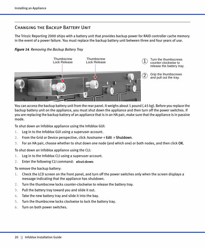
Changing the Backup Battery Unit
The Trinzic Reporting 2000 ships with a battery unit that provides backup power for RAID controller cache memory
in the event of a power failure. You must replace the backup battery unit between three and four years of use.
Figure 14 Removing the Backup Battery Tray
You can access the backup battery unit from the rear panel. It weighs about 1 pound (.45 kg). Before you replace the
backup battery unit on the appliance, you must shut down the appliance and then turn off the power switches. If
you are replacing the backup battery of an appliance that is in an HA pair, make sure that the appliance is in passive
mode.
To shut down an Infoblox appliance using the Infoblox GUI:
1. Log in to the Infoblox GUI using a superuser account.
2. From the Grid or Device perspective, click hostname -> Edit -> Shutdown.
3. For an HA pair, choose whether to shut down one node (and which one) or both nodes, and then click OK.
To shut down an Infoblox appliance using the CLI:
1. Log in to the Infoblox CLI using a superuser account.
2. Enter the following CLI command: shutdown
To remove the backup battery:
1. Check the LCD screen on the front panel, and turn off the power switches only when the screen displays a
message indicating that the appliance has shutdown.
2. Turn the thumbscrew locks counter-clockwise to release the battery tray.
3. Pull the battery tray toward you and slide it out.
4. Take the new battery tray and slide it into the bay.
5. Turn the thumbscrew locks clockwise to lock the battery tray.
6. Turn on both power switches.
Grip the thumbscrews and pull out the tray.
1
2
Thumbscrew Lock Release
Thumbscrew Lock Release
Turn the thumbscrews counter-clockwise to release the battery tray.
20 Infoblox Installation Guide
Accessing the Appliance
The management system is the computer from which you configure and monitor the Infoblox appliance. You can
access the appliance from the management system remotely across an Ethernet network or directly through a serial
cable.
After completing the steps in Cabling the Appliance to a Network on page 14, you can make an HTTPS connection to
the appliance and access the Infoblox GUI using one of the supported browsers.
Alternatively, you can make an SSHv2 connection and access the CLI through an SSHv2 client. You can also access
the CLI by connecting a serial cable directly from the console port of a management system to the console port on
the appliance, and then using a terminal emulation program.
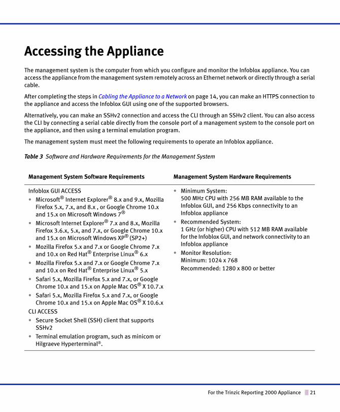
The management system must meet the following requirements to operate an Infoblox appliance.
Table 3 Software and Hardware Requirements for the Management System
Management System Software Requirements Management System Hardware Requirements
Infoblox GUI ACCESS
• Microsoft® Internet Explorer® 8.x and 9.x, Mozilla
Firefox 5.x, 7.x, and 8.x , or Google Chrome 10.x
and 15.x on Microsoft Windows 7®
• Microsoft Internet Explorer® 7.x and 8.x, Mozilla
Firefox 3.6.x, 5.x, and 7.x, or Google Chrome 10.x
and 15.x on Microsoft Windows XP® (SP2+)
• Mozilla Firefox 5.x and 7.x or Google Chrome 7.x
and 10.x on Red Hat® Enterprise Linux® 6.x
• Mozilla Firefox 5.x and 7.x or Google Chrome 7.x
and 10.x on Red Hat® Enterprise Linux® 5.x
• Safari 5.x, Mozilla Firefox 5.x and 7.x, or Google
Chrome 10.x and 15.x on Apple Mac OS® X 10.7.x
• Safari 5.x, Mozilla Firefox 5.x and 7.x, or Google
Chrome 10.x and 15.x on Apple Mac OS® X 10.6.x
CLI ACCESS
• Secure Socket Shell (SSH) client that supports
SSHv2
• Terminal emulation program, such as minicom or
Hilgraeve Hyperterminal®.
• Minimum System: 500 MHz CPU with 256 MB RAM available to the
Infoblox GUI, and 256 Kbps connectivity to an
Infoblox appliance
• Recommended System: 1 GHz (or higher) CPU with 512 MB RAM available
for the Infoblox GUI, and network connectivity to an
Infoblox appliance
• Monitor Resolution: Minimum: 1024 x 768
Recommended: 1280 x 800 or better
For the Trinzic Reporting 2000 Appliance 21
Accessing the Appliance
Connecting to the Appliance
Before you can configure the Infoblox appliance through the Infoblox GUI, you must be able to make a network
connection to it. You must use the LAN1 port to connect to the appliance. The default network settings of the LAN1
port are 192.168.1.2/24 with a gateway at 192.168.1.1 (the HA, MGMT, and LAN2 ports do not have default
network settings). To change these settings to suit your network, use either the LCD or the console port.
LCD
The Infoblox appliance has an LCD and navigation buttons on its front panel. At startup, the Infoblox logo appears
in the LCD on the front panel of the appliance. Then the LCD scrolls repeatedly through a series of display screens.
1. To change the network settings from the default, press one of the navigation buttons.
The LCD immediately goes into input mode.
2. Use the navigation buttons to enter the IP address, netmask, and gateway for the LAN1 port.
You can disable LCD input functionality. To disable the LCD, refer to the NIOS Administrator Guide.
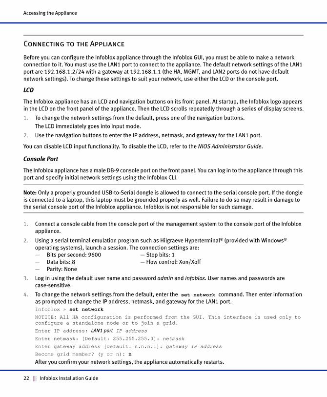
Console Port
The Infoblox appliance has a male DB-9 console port on the front panel. You can log in to the appliance through this
port and specify initial network settings using the Infoblox CLI.
Note: Only a properly grounded USB-to-Serial dongle is allowed to connect to the serial console port. If the dongle
is connected to a laptop, this laptop must be grounded properly as well. Failure to do so may result in damage to
the serial console port of the Infoblox appliance. Infoblox is not responsible for such damage.
1. Connect a console cable from the console port of the management system to the console port of the Infoblox
appliance.
2. Using a serial terminal emulation program such as Hilgraeve Hyperterminal® (provided with Windows®
operating systems), launch a session. The connection settings are:
— Bits per second: 9600 — Stop bits: 1
— Data bits: 8 — Flow control: Xon/Xoff
— Parity: None
3. Log in using the default user name and password admin and infoblox. User names and passwords are
case-sensitive.
4. To change the network settings from the default, enter the set network command. Then enter information
as prompted to change the IP address, netmask, and gateway for the LAN1 port.
Infoblox > set network
NOTICE: All HA configuration is performed from the GUI. This interface is used only to configure a standalone node or to join a grid.
Enter IP address: LAN1 port IP address
Enter netmask: [Default: 255.255.255.0]: netmask
Enter gateway address [Default: n.n.n.1]: gateway IP address
Become grid member? (y or n): n
After you confirm your network settings, the appliance automatically restarts.
22 Infoblox Installation Guide
Specifying Appliance Settings
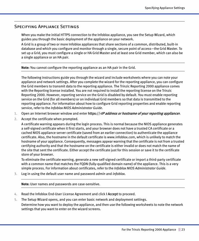
Specifying Appliance Settings
When you make the initial HTTPS connection to the Infoblox appliance, you see the Setup Wizard, which
guides you through the basic deployment of the appliance on your network.
A Grid is a group of two or more Infoblox appliances that share sections of a common, distributed, built-in
database and which you configure and monitor through a single, secure point of access—the Grid Master. To
set up a Grid, you must configure a single or HA Grid Master and at least one Grid member, which can also be
a single appliance or an HA pair.
Note: You cannot configure the reporting appliance as an HA pair in the Grid.
The following instructions guide you through the wizard and include worksheets where you can note your
appliance and network settings. After you complete the wizard for the reporting appliance, you can configure
the Grid members to transmit data to the reporting appliance. The Trinzic Reporting 2000 appliance comes
with the Reporting license installed. You are not required to install the reporting license on the Trinzic
Reporting 2000. However, reporting service on the Grid is disabled by default. You must enable reporting
service on the Grid (for all members) or on individual Grid members so that data is transmitted to the
reporting appliance. For information about how to configure Grid reporting properties and enable reporting
service, refer to the Infoblox NIOS Administrator Guide.
1. Open an Internet browser window and enter https://<IP address or hostname of your reporting appliance>.
2. Accept the certificate when prompted.
A certificate warning appears during the login process. This is normal because the NIOS appliance generates
a self-signed certificate when it first starts, and your browser does not have a trusted CA certificate or a
cached NIOS appliance server certificate (saved from an earlier connection) to authenticate the appliance
certificate. Also, the hostname in the default certificate is www.infoblox.com, which is unlikely to match the
hostname of your appliance. Consequently, messages appear warning that the certificate is not from a trusted
certifying authority and that the hostname on the certificate is either invalid or does not match the name of
the site that sent the certificate. Either accept the certificate just for this session or save it to the certificate
store of your browser.
To eliminate the certificate warning, generate a new self-signed certificate or import a third-party certificate
with a common name that matches the FQDN (fully-qualified domain name) of the appliance. This is a very
simple process. For information about certificates, refer to the Infoblox NIOS Administrator Guide.
3. Log in using the default user name and password admin and infoblox.
Note: User names and passwords are case-sensitive.
4. Read the Infoblox End-User License Agreement and click I Accept to proceed.
5. The Setup Wizard opens, and you can enter basic network and deployment settings.
Determine how you want to deploy the appliance, and then use the following worksheets to note the network
settings that you want to enter on the wizard screens.
For the Trinzic Reporting 2000 Appliance 23
Accessing the Appliance
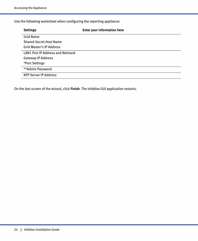
Use the following worksheet when configuring the reporting appliance:
On the last screen of the wizard, click Finish. The Infoblox GUI application restarts.
Settings Enter your information here
Grid Name
Shared Secret Host Name
Grid Master’s IP Address
LAN1 Port IP Address and Netmask
Gateway IP Address
*Port Settings
**Admin Password
NTP Server IP Address
24 Infoblox Installation Guide
Infoblox GUI
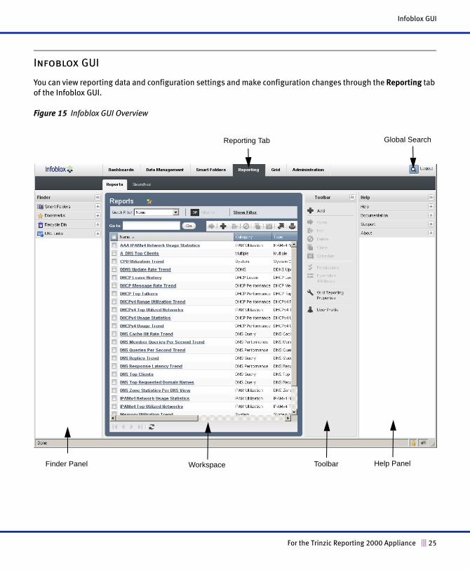
Infoblox GUI
You can view reporting data and configuration settings and make configuration changes through the Reporting tab
of the Infoblox GUI.
Figure 15 Infoblox GUI Overview
Finder Panel Workspace Toolbar
Global SearchReporting Tab
Help Panel
For the Trinzic Reporting 2000 Appliance 25
Accessing the Appliance
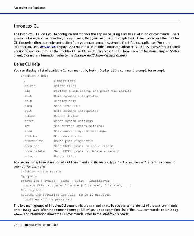
Infoblox CLI
The Infoblox CLI allows you to configure and monitor the appliance using a small set of Infoblox commands. There
are some tasks, such as resetting the appliance, that you can only do through the CLI. You can access the Infoblox
CLI through a direct console connection from your management system to the Infoblox appliance. (For more
information, see Console Port on page 22.) You can also enable remote console access—that is, SSHv2 (Secure Shell
version 2) access—through the Infoblox GUI or CLI, and then access the CLI from a remote location using an SSHv2
client. (For more information, refer to the Infoblox NIOS Administrator Guide.)
Using CLI Help
You can display a list of available CLI commands by typing help at the command prompt. For example:
Infoblox > help
? Display help
delete Delete files
dig Perform a DNS lookup and print the results
exit Exit command interpreter
help Display help
ping Send ICMP ECHO
quit Exit command interpreter
reboot Reboot device
reset Reset system settings
set Set current system settings
show Show current system settings
shutdown Shutdown device
traceroute Route path diagnostic
ddns_add Send DDNS update to add a record
ddns_delete Send DDNS update to delete a record
rotate Rotate files
To view an in-depth explanation of a CLI command and its syntax, type help command after the command
prompt. For example:
Infoblox > help rotate
Synopsis:
rotate log [ syslog | debug | audit | ifmapserver ]
rotate file groupname filename [ filename2, filename3, ...]
Description:
Rotates the specified log file, up to 10 previous.
logfiles will be preserved
The two main groups of Infoblox CLI commands are set and show. To see the complete list of the set commands,
enter help set after the command prompt. Likewise, to see a complete list of the show commands, enter help show . For information about the CLI commands, refer to the Infoblox CLI Guide.
26 Infoblox Installation Guide
Managing the Disk Subsystem
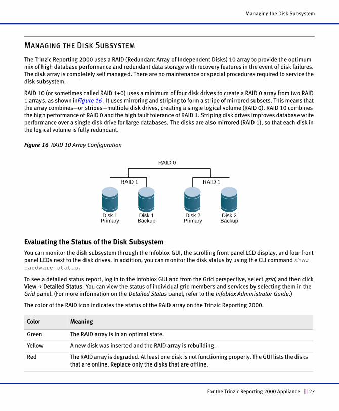
Managing the Disk Subsystem
The Trinzic Reporting 2000 uses a RAID (Redundant Array of Independent Disks) 10 array to provide the optimum
mix of high database performance and redundant data storage with recovery features in the event of disk failures.
The disk array is completely self managed. There are no maintenance or special procedures required to service the
disk subsystem.
RAID 10 (or sometimes called RAID 1+0) uses a minimum of four disk drives to create a RAID 0 array from two RAID
1 arrays, as shown inFigure 16 . It uses mirroring and striping to form a stripe of mirrored subsets. This means that
the array combines—or stripes—multiple disk drives, creating a single logical volume (RAID 0). RAID 10 combines
the high performance of RAID 0 and the high fault tolerance of RAID 1. Striping disk drives improves database write
performance over a single disk drive for large databases. The disks are also mirrored (RAID 1), so that each disk in
the logical volume is fully redundant.
Figure 16 RAID 10 Array Configuration
Evaluating the Status of the Disk Subsystem
You can monitor the disk subsystem through the Infoblox GUI, the scrolling front panel LCD display, and four front
panel LEDs next to the disk drives. In addition, you can monitor the disk status by using the CLI command show hardware_status.
To see a detailed status report, log in to the Infoblox GUI and from the Grid perspective, select grid, and then click
View -> Detailed Status. You can view the status of individual grid members and services by selecting them in the
Grid panel. (For more information on the Detailed Status panel, refer to the Infoblox Administrator Guide.)
The color of the RAID icon indicates the status of the RAID array on the Trinzic Reporting 2000.
Color Meaning
Green The RAID array is in an optimal state.
Yellow A new disk was inserted and the RAID array is rebuilding.
Red The RAID array is degraded. At least one disk is not functioning properly. The GUI lists the disks
that are online. Replace only the disks that are offline.
Disk 1 Primary
Disk 1 Backup
Disk 2 Primary
Disk 2 Backup
RAID 1 RAID 1
RAID 0
For the Trinzic Reporting 2000 Appliance 27
Accessing the Appliance
The Infoblox GUI also displays detailed status of the RAID array. In the event of a disk failure, you must replace the
failed disk with one that is qualified and shipped from Infoblox and has the same disk type as the rest of the disks
in the array. The appliance displays information about mismatched disks in the Description column in the Detailed
Status panel. The disk type can be one of the following:
• IB-Type 1: Infoblox supported disk type
• IB-Type 2: Infoblox supported disk type
• Unk: Unknown disk type that Infoblox does not support
All disk drives in the array must have the same disk type for the array to function properly. You can have either
IB-Type 1 or IB-Type 2, but you cannot mix both in the array. When you have a mismatched disk in the array, you
must promptly replace the disk with a replacement disk from Infoblox to avoid operational issues.
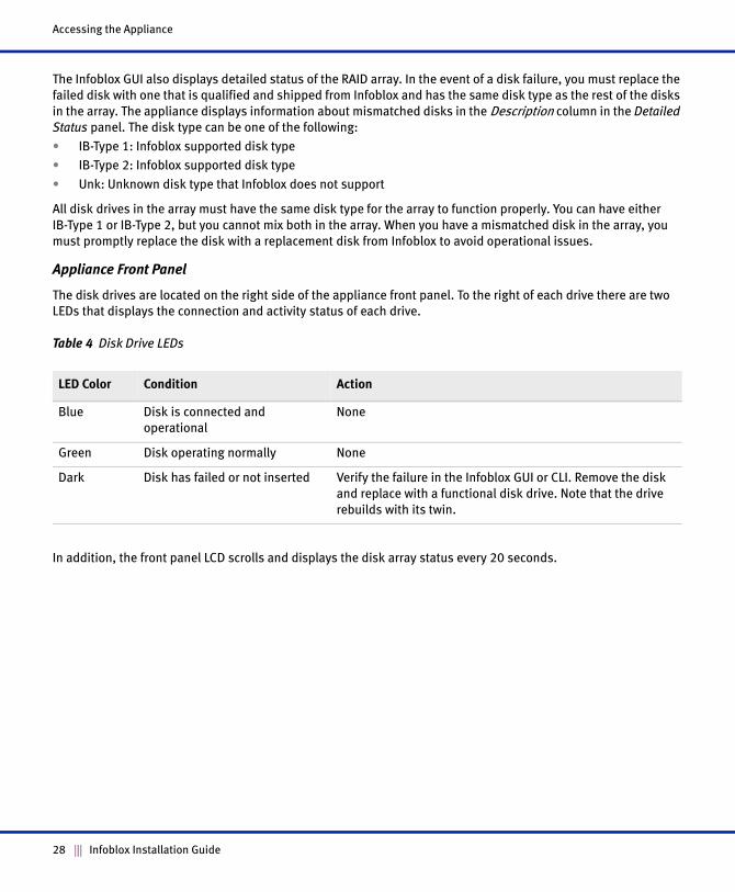
Appliance Front Panel
The disk drives are located on the right side of the appliance front panel. To the right of each drive there are two
LEDs that displays the connection and activity status of each drive.
Table 4 Disk Drive LEDs
In addition, the front panel LCD scrolls and displays the disk array status every 20 seconds.
LED Color Condition Action
Blue Disk is connected and
operational
None
Green Disk operating normally None
Dark Disk has failed or not inserted Verify the failure in the Infoblox GUI or CLI. Remove the disk
and replace with a functional disk drive. Note that the drive
rebuilds with its twin.
28 Infoblox Installation Guide