Embed Size (px)
Citation preview
INFLUENCE OF NON-METALLIC INCLUSIONSIN SUPER-FINISH WIRE CUTTING
F. Klocke, T. Nothe and M. KlotzLaboratory for Machine Tools and Production Engineering
Department of Manufacturing Technology
Aachen University of Technology
RWTH Aachen
Abstract Todaywire-EDM(wire-Electro-Discharge-Machining) isamostlyautonomousprocess due to the developments in the fields of generator technology, pro-cess knowledge, wire electrodes and control techniques. Until now almostno attention has been paid to the question to what extent the quality andthe production method of the workpiece material have an influnce on thesurface quality and outline accuracy of the machined workpiece. In the re-search project presented here was examined systematicallyto what extentthe degree of purity, homogeneity, carbide size and distribution (and withit concomitantly the manufacture method) of tool steels influence the resultof super-finish wire cutting (WEDM). These investigations serve the aim todefine concrete requests to the characteristics of the workpiece material independency of a given quality target.
Keywords: Tool and Die Manufacturing, Wire-EDM, Non-Metallic Inclusions
INTRODUCTION
In the modern production of tools (especially for pressing,cutting, fineblanking or extruding) wire-EDM is an integral and not replaceable part ofthe process chain. As the machining principle is based on thermal erosionof the workpiece this technology works completely independent from theworkpiece hardness. Since the introduction of this machining process intoindustrial practice in the nineteenseventies the cutting rates for steel of ini-tially approx. 30 mm2/min rose up to 300 mm2/min. Surface qualities up
1183
1184 6TH INTERNATIONAL TOOLING CONFERENCE
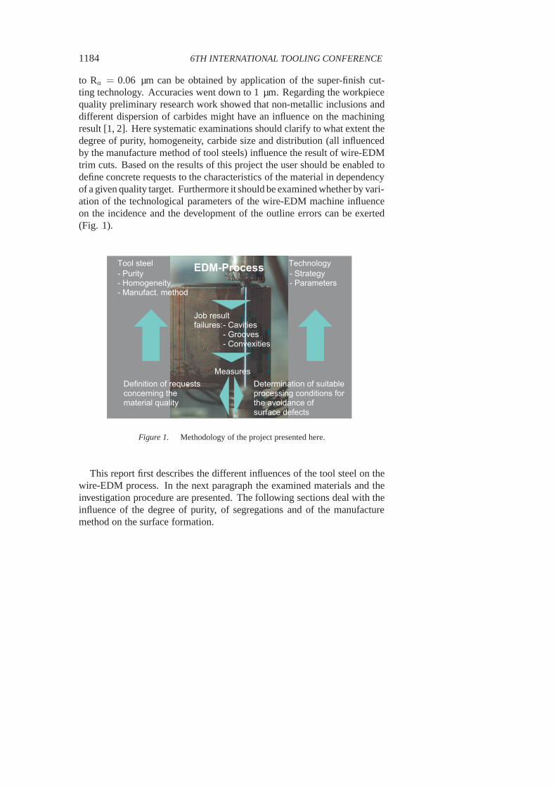
to Ra = 0.06 µm can be obtained by application of the super-finish cut-ting technology. Accuracies went down to 1 µm. Regarding theworkpiecequality preliminary research work showed that non-metallic inclusions anddifferent dispersion of carbides might have an influence on the machiningresult [1, 2]. Here systematic examinations should clarifyto what extent thedegree of purity, homogeneity, carbide size and distribution (all influencedby the manufacture method of tool steels) influence the result of wire-EDMtrim cuts. Based on the results of this project the user should be enabled todefine concrete requests to the characteristics of the material in dependencyof a given quality target. Furthermore it should be examinedwhether by vari-ation of the technological parameters of the wire-EDM machine influenceon the incidence and the development of the outline errors can be exerted(Fig. 1).
E D M - P r o c e s sT o o l s t e e l- P u r i t y- H o m o g e n e i t y- M a n u f a c t . m e t h o d
M e a s u r e sD e t e r m i n a t i o n o f s u i t a b l ep r o c e s s i n g c o n d i t i o n s f o rt h e a v o i d a n c e o fs u r f a c e d e f e c t s
D e f i n i t i o n o f r e q u e s t sc o n c e r n i n g t h e m a t e r i a l q u a l i t y
- S t r a t e g y- P a r a m e t e r sT e c h n o l o g y
J o b r e s u l tf a i l u r e s : - C a v i t i e s
- G r o o v e s- C o n v e x i t i e s
Figure 1. Methodology of the project presented here.
This report first describes the different influences of the tool steel on thewire-EDM process. In the next paragraph the examined materials and theinvestigation procedure are presented. The following sections deal with theinfluence of the degree of purity, of segregations and of the manufacturemethod on the surface formation.
Influence of Non-Metallic Inclusions in Super-Finish Wire Cutting 1185
MATERIAL CHARACTERISTICS INFLUENCING THEWIRE-EDM PROCESS
As mentioned above the mechanical material properties playa subordi-nated role in spark erosion. Impurities in the form of non-metallic inclusionsare of special importance, since they can entail process disturbances and out-line errors. The electrically non-conductive inclusions can be removed onlyindirectly or not at all by means of trim cuts with subsequently reduceddischarge energy. The following mechanisms are possible:
The wire electrode will be deflected at the inclusion, so thata bump onthe component surface develops. This requires an accordingly smallworking gap.
The inclusion is extracted of the surrounding matrix and leaves a cavityin the component.
The inclusion is molten or evaporated by thermal conduction[3, 4].The precipitation of these different effects depends on theheight ofthe discharge energy and on the melting point as well as on thekindof inclusion and on the gap width.
METHOD OF INVESTIGATIONS
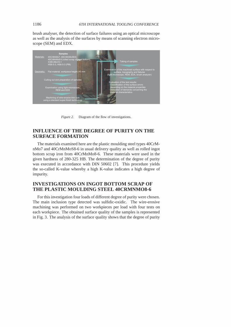
The flow of investigations was as follows (Fig. 2): The materials in thisproject were chosen according to the needs of tool and die manufacturers,especially those making tools for injection moulding [5, 6]. The raw mate-rial of the plastic moulding steel had the hardness as supplied by the steelmanufacturer, while the hot-work tool steel and the two high-speed steelswere hardened. This corresponds to practice. After hardening samples werecut out by wire-EDM. These samples were prepared by grindingand pol-ishing and were afterwards submitted to a structural examination using anoptical microscope in order to determine the initial state of the material.Additionally EDX (Energy-Dispersive X-Ray Spectroscopy)analyses wereexecuted to identify certain elements and compounds. In thenext step ofthe examination sequence flat samples were cut out using a standard super-finish technology with three to five trim cuts. The surfaces ofthese sampleswere submitted to a detailed analysis for evaluation of the test results. Thiscontained the measurement of surface roughness in feed direction with a
1186 6TH INTERNATIONAL TOOLING CONFERENCE
brush analyser, the detection of surface failures using an optical microscopeas well as the analysis of the surfaces by means of scanning electron micro-scope (SEM) and EDX.
T a k i n g o f s a m p l e s
E x a m i n a t i o n o f t h e m a c h i n e d s u r f a c e w i t h r e s p e c t t os u r f a c e , t o p o g r a p h y a n d f a i l u r e s
( l i g h t m i c r o s c o p e , R E M , E D X , b r u s h a n a l y z e r )
S a m p l e s4 0 C r M n M o 7 , 4 0 C r M n M o S 8 - 6 , 4 0 C r M n M o 8 - 6 ( r o l l e d s c r a p o f i n g o t b o t t o m ) ,X 3 8 C r M o V 5 - 1H S 6 - 5 - 3 , H S 6 - 5 - 3 ( P M )
C u t t i n g o u t a n d p r e p a r a t i o n o f s a m p l e s
E x a m i n a t i o n u s i n g l i g h t - m i c r o s c o p e ,R E M a n d E D X
M a c h i n i n g o f w i r e - e r o s i v e t r i m c u t su s i n g a s t a n d a r d s u p e r - f i n i s h t e c h n o l o g y
G e o m e t r y : F l a t m a t e r i a l , w o r k p i e c e h e i g h t : 4 0 m m
M a t e r i a l s :
E v a l u a t i o n o f t h e t e s t r e s u l t s :- C l a s s i f i c a t i o n o f t h e s u r f a c e e r r o r s d e p e n d i n g o n t h e m a t e r i a l p r o p e r t i e s- D e d u c t i o n o f d e m a n d s c o n c e r n i n g t h e m a t e r i a l c h a r a c t e r i s t i c s
Figure 2. Diagram of the flow of investigations.
INFLUENCE OF THE DEGREE OF PURITY ON THESURFACE FORMATION
The materials examined here are the plastic moulding steel types 40CrM-nMo7 and 40CrMnMoS8-6 in usual delivery quality as well as rolled ingotbottom scrap iron from 40CrMnMo8-6. These materials were used in thegiven hardness of 280-325 HB. The determination of the degree of puritywas executed in accordance with DIN 50602 [7]. This procedure yieldsthe so-called K-value whereby a high K-value indicates a high degree ofimpurity.
INVESTIGATIONS ON INGOT BOTTOM SCRAP OFTHE PLASTIC MOULDING STEEL 40CRMNMO8-6
For this investigation four loads of different degree of purity were chosen.The main inclusion type detected was sulfidic-oxidic. The wire-erosivemachining was performed on two workpieces per load with fourtests oneach workpiece. The obtained surface quality of the samplesis representedin Fig. 3. The analysis of the surface quality shows that the degree of purity

Influence of Non-Metallic Inclusions in Super-Finish Wire Cutting 1187
exerts a clear influence on the job result only starting from the fourth trimcut, i.e. starting from a desired surface quality of approx.Ra = 0.2 µm. Thedischarge energy is obviously still sufficient in the third trim cut to extractthe inclusions from the matrix without wire deflection. Furthermore theshrinking gap width depending on sinking discharge energy (only approx.6 µm in the fifth trim cut) influences the risk of contact. Herein a furthercause for the number of outline errors rising with the machining level isto be seen. Furthermore it becomes clear that only in the fourth and fifthtrim cut a K4-value (explained in [7]) starting from 15–20 results in outlineerrors. Furthermore the job result depends on the machiningdirection. Withcutting in rolling direction, the inclusions represents a higher portion of themachined surface than with cutting transversely to the direction of rolling.This is reflected in the obtained surface roughnesses and in the frequency ofthe outline errors.
D e g r e e o f P u r i t y K 4
R max, 1
0*Ra
0
0 . 5
1
1 . 5
2
2 . 5
µ m
3 . 5
5 1 7 . 5 2 0 2 7 . 5
amou
nt of
outlin
e failure
spe
r 10 m
m
R a
R m a x
n u m b e r o f o u t l i n e e r r o r s / 1 0 m m
0
0 . 5
1
1 . 5
2
2 . 5
3
3 . 5
Figure 3. Surface quality after the 5th trimcut in rolling direction.
Using a scanning electron microscope, errors in the form of cavities couldbe determined which go back to the extraction of non-metallic inclusions.There were no inclusions remaining in the workpiece surfaceso that a directallocation of the inclusions to wire deflection-caused crests was not possible.
1188 6TH INTERNATIONAL TOOLING CONFERENCE
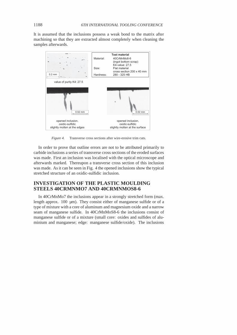
It is assumed that the inclusions possess a weak bond to the matrix aftermachining so that they are extracted almost completely whencleaning thesamples afterwards.
0 . 2 m m
v a l u e o f p u r i t y K 4 : 2 7 . 5
o p e n e d i n c l u s i o n ,o x i d i c - s u l f i d i c
s l i g h t l y m o l t e n a t t h e e d g e so p e n e d i n c l u s i o n ,o x i d i c - s u l f i d i c
s l i g h t l y m o l t e n a t t h e s u r f a c e
T e s t m a t e r i a lM a t e r i a l :
S i z e :H a r d n e s s :
4 0 C r M n M o 8 - 6( i n g o t b o t t o m s c r a p )K 4 - v a l u e : 2 7 . 5F l a t m a t e r i a lc r o s s s e c t i o n 2 0 0 x 4 0 m m2 8 0 - 3 2 5 H B
0 . 0 2 m m 0 . 0 2 m m
Figure 4. Transverse cross sections after wire-erosive trim cuts.
In order to prove that outline errors are not to be attributedprimarily tocarbide inclusions a series of transverse cross sections ofthe eroded surfaceswas made. First an inclusion was localised with the optical microscope andafterwards marked. Thereupon a transverse cross section ofthis inclusionwas made. As it can be seen in Fig. 4 the opened inclusions showthe typicalstretched structure of an oxidic-sulfidic inclusion.
INVESTIGATION OF THE PLASTIC MOULDINGSTEELS 40CRMNMO7 AND 40CRMNMOS8-6
In 40CrMnMo7 the inclusions appear in a strongly stretched form (max.length approx. 100 µm). They consist either of manganese sulfide or of atype of mixture with a core of aluminum and magnesium oxide and a narrowseam of manganese sulfide. In 40CrMnMoS8-6 the inclusions consist ofmanganese sulfide or of a mixture (small core: oxides and sulfides of alu-minium and manganese; edge: manganese sulfide/oxide). The inclusions
Influence of Non-Metallic Inclusions in Super-Finish Wire Cutting 1189
have coagulated structures with a max. length of approx. 100µm. Alto-gether the K-values are substantially higher with 40CrMnMoS8-6 due to thehigher sulfur content (approx. 0.07 %) in comparison with 40CrMnMo7(approx. 0.003 %).
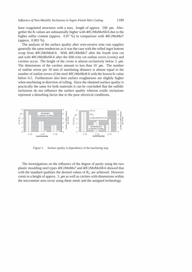
The analysis of the surface quality after wire-erosive trimcuts suppliesgenerally the same tendencies as it was the case with the rolled ingot bottomscrap from 40CrMnMo8-6. With 40CrMnMo7 after the fourth trim cutand with 40CrMnMoS8-6 after the fifth trim cut outline errors(crests) andcavities occur. The height of the crests is almost exclusively below 5 µm.The dimensions of the cavities amount to less than 10 µm. The numberof outline errors per 10 mm of machining distance is almost equal to thenumber of outline errors of the steel 40CrMnMo8-6 with the lowest K-valuebelow 0.5. Furthermore also here surface roughnesses are slightly higherwhen machining in direction of rolling. Since the obtained surface quality ispractically the same for both materials it can be concluded that the sulfidicinclusions do not influence the surface quality whereas oxidic inclusionsrepresent a disturbing factor due to the poor electrical conditions.
0
1
2
3
µ m
5
3 . T C 4 . T C 5 . T Cm a c h i n i n g s t e p
4 0 C r M n M o 7i n d i r e c t i o n o f r o l l i n g
R a*10
, Rma
x
0
1
2
3
4
5
numb
er of
outlin
e failure
spe
r 10 m
m
0
1
2
3
µ m
5
3 . T C 4 . T C 5 . T C
R a * 1 0R m a x
o u t l i n e f a i l u r e s / 1 0 m m
R a*10
, Rma
x
0
1
2
3
4
5
numb
er of
outlin
e failure
spe
r 10 m
m
4 0 C r M n M o S 8 - 6i n d i r e c t i o n o f r o l l i n g
m a c h i n i n g s t e p
Figure 5. Surface quality in dependence of the machining step.
The investigations on the influence of the degree of purity using the twoplastic moulding steel types 40CrMnMo7 and 40CrMnMoS8-6 showed thatwith the standard qualities the desired values of Ra are achieved. Howevercrests to a height of approx. 5 µm as well as cavities with dimensions withinthe micrometer area occur using these steels and the assigned technology.

1190 6TH INTERNATIONAL TOOLING CONFERENCE
INFLUENCE OF SEGREGATIONS ON THE SURFACEFORMATION
The microscopic check of the samples of the hot-working toolsteelX38CrMoV5-1 (1.2343) was made in the annealed state. In order to exam-ine the influence of segregations over the entire workpiece width, samplesof the center as well as of the edge of the workpieces were cut out. Thecross section surface which was examined is thereby in rolling direction.Analyses and evaluation of the cross sections were carried out in accordancewith Stahl-Eisen test sheet 1614 [8]. Figure 6 shows the comparison of theoptical microscope photos with the equivalent reference pictures taken from[8]. The pictures are representative for all sample positions. No segregationlines are present.
o p t i c a l m i c r o s c o p i c e x a m i n a t i o nX 3 8 C r M o V 5 - 1
c o m p a r i s o n t a k e n f r o mt h e V D E h - s t a n d a r d s
Magn
ificati
on 50
xMa
gnific
ation
500x
G A 3
S A 10 . 5 m m
0 . 0 5 m m
0 . 5 m m
0 . 0 5 m m
Figure 6. Structure of X38CrMoV5-1 used here compared with the VDEh standards.
The wire-erosive cuts were executed in direct proximity of the pointswhere the cross section samples were taken. In this point of the projectmachining transverse to the direction of rolling was not examined. The

Influence of Non-Metallic Inclusions in Super-Finish Wire Cutting 1191
s u r f a c e q u a l i t y o f a c e n t e r p i e c e
0123456
3 . T C 4 . T C 5 . T C
R a*10
, Rma
x
R a * 1 0R m a x
n u m b e r o f o u t l i n ef a i l u r e s / 1 0 m m
0123456
numb
er of
outlin
e erro
rspe
r 10 m
m
s u r f a c e q u a l i t y o f a p i e c e c l o s e t o t h e e d g e
0123456
3 . T C 4 . T C 5 . T C
R a*10
, Rma
x
R a * 1 0R m a x
n u m b e r o f o u t l i n ef a i l u r e s / 1 0 m m
0123456
numb
er of
outlin
e erro
rspe
r 10 m
m
Figure 7. Surface qualities with X38CrMoV5-1 in center and edge piece.
results of the surface analysis of the eroded samples are shown in Fig. 7. Asthe cross section investigations suggest, first of all no significant differenceresults from the cut position, and secondly the desired Ra -values are achievedas far as possible. However outline errors with a dimension up to 3 µm alsooccur in the fifth trim cut when using this steel. This indicates that this steelis not free of impurities either.
INFLUENCE OF THE MANUFACTURE METHOD OFHIGH-SPEED STEEL ON THE SURFACE FORMATION
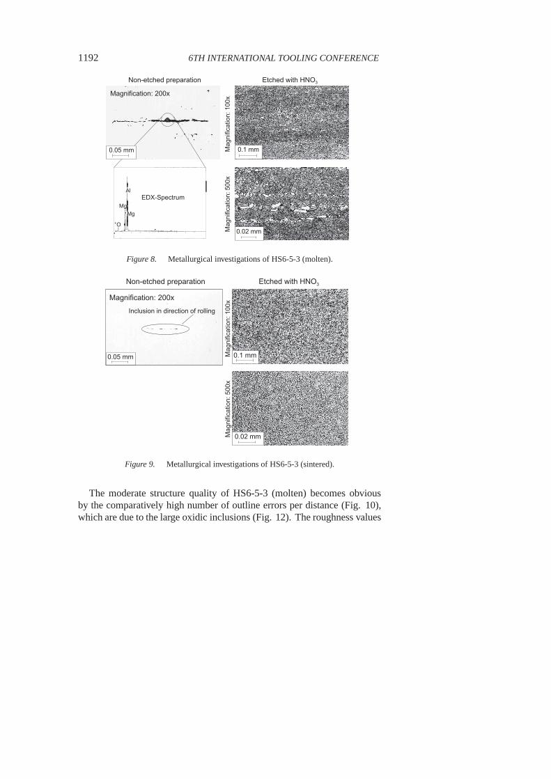
Within this topic the high-speed steel HS6-5-3 (1.3344) in the pyromet-allurgical as well as in the powder metallurgical version were examined.Position, geometry and dimensions of the cross section samples and cutswere selected similarly to the tests on the plastic mouldingsteel types. Be-fore the microscopic analysis the workpieces were recompensed on 62 HRC.The analysis covered six samples per version. Figure 8 showsfirst the resultsof this analysis for HS6-5-3 (molten). This steel indicatesobvious oxidicinclusions, segregations as well as clear carbide lines.
The analysis of the powder metallurgical steel shows a homogeneous andsegregation-free structure with a small number of sulfidic inclusions (Fig.9). These differences are based on the sinter-technical manufacture method,with which segregations in the usual sense cannot occur. Furthermore thecarbides possess substantially smaller dimensions.
At each steel eight tests consisting of one main cut and five trim cuts wereexecuted. The test results are represented in the Fig. 10 andFig. 11. Con-cerning HS6-5-3 (sintered) a separation of the results regarding the directionof rolling was omitted because of the missing significant anisotropy.
1192 6TH INTERNATIONAL TOOLING CONFERENCE
1 7 5 3
1 7 5 01 8 0 9
0 . 1 m m
0 . 0 2 m m
N o n - e t c h e d p r e p a r a t i o n E t c h e d w i t h H N O 3
M a g n i f i c a t i o n : 2 0 0 x
Magn
ificati
on: 1
00x
Magn
ificati
on: 5
00x
A l
M gM g
O
E D X - S p e c t r u m
0 . 0 5 m m
Figure 8. Metallurgical investigations of HS6-5-3 (molten).
4 4 5 1
4 4 4 74 4 7 3
0 . 1 m m
0 . 0 2 m m
0 . 0 5 m m
N o n - e t c h e d p r e p a r a t i o n E t c h e d w i t h H N O 3
M a g n i f i c a t i o n : 2 0 0 x
Magn
ificati
on: 1
00x
Magn
ificati
on: 5
00x
I n c l u s i o n i n d i r e c t i o n o f r o l l i n g
Figure 9. Metallurgical investigations of HS6-5-3 (sintered).
The moderate structure quality of HS6-5-3 (molten) becomesobviousby the comparatively high number of outline errors per distance (Fig. 10),which are due to the large oxidic inclusions (Fig. 12). The roughness values
Influence of Non-Metallic Inclusions in Super-Finish Wire Cutting 1193
M a c h i n i n g i n d i r e c t i o n o f r o l l i n g
0
1
2
3
5
3 . T C 4 . T C 5 . T C
µ mR aR m a x
n u m b e r o f o u t l i n e e r r o r s / 1 0 m m
0
1
2
3
4
5
R a*10
, Rma
x
numb
er of
outlin
e erro
rspe
r 10 m
m
M a c h i n i n g t r a n s v e r s e t o d i r e c t i o n o f r o l l i n g
0
1
2
4
3 . T C 4 . T C 5 . T C
µ m
0
1
2
3
4
R a*10
, Rma
x
numb
er of
outlin
e erro
rspe
r 10 m
m
R aR m a x
n u m b e r o f o u t l i n e e r r o r s / 1 0 m m
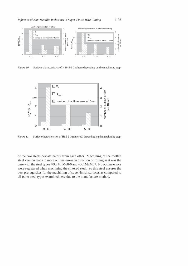
Figure 10. Surface characteristics of HS6-5-3 (molten) depending on the machining step.
numb
er of
outlin
e erro
rspe
r 10 m
m
0
1
2
µ m
4
3 . T C 4 . T C 5 . T C0
1
2
3
4R a
R m a x
n u m b e r o f o u t l i n e e r r o r s / 1 0 m m
R a*10
, Rma
x
Figure 11. Surface characteristics of HS6-5-3 (sintered) depending on the machining step.
of the two steels deviate hardly from each other. Machining of the moltensteel version leads to more outline errors in direction of rolling as it was thecase with the steel types 40CrMnMo8-6 and 40CrMnMo7. No outline errorswere registered when machining the sintered steel. So this steel ensures thebest prerequisites for the machining of super-finish surfaces as compared toall other steel types examined here due to the manufacture method.

1194 6TH INTERNATIONAL TOOLING CONFERENCE
A l
S i F e
F e
VS i F eVV
E D X - A n a l y s e sS E M - p h o t o a f t e r t h e f i f t h t r i m c u t
Figure 12. Surface failure due to an oxidic inclusion in HS6-5-3 (molten).
INFLUENCE OF THE TECHNOLOGICALPARAMETERS
To make clear whether there are process parameters where non-metallicinclusions, carbides and segregations have little or no influence on the jobresult two machining strategies deviating from the standard were examined.Using a standard technology the lateral feed is 5 µm in the fifth trim cut. Thefeed rate in cutting direction is constant – not as in trim cut1 to 3, where thefeed rate is adapted to the respective discharge current. The first non-standardmachining strategy operates with a fixed feed rate and without lateral feed.Target here was it to reduce the probability of a wire deflection by a non-metallic inclusion. It was guaranteed in preliminary teststhat also withoutlateral feed a constant erosion takes place. In the second strategy the machinecontrol operates with a fixed feed speed, here likewise with short-circuitretreat, i.e. on detecting a short-circuit the machine draws back the wireagainst the machining direction and tries to process this place again. Withthis machining strategy it was intended to remove sufficiently electricallyconductive inclusions or to process the crests which developed before. Theexamined material was again the plastic moulding steel 40CrMnMo8-6, hereespecially a load from rolled ingot bottom scrap with a K4-value of 27.5.This material indicated a comparatively high number of outline errors (Fig.

Influence of Non-Metallic Inclusions in Super-Finish Wire Cutting 1195
3) at earlier points of investigation and is thus especiallysuitable in order totest the potential of the different machining strategies.
3 . T C 4 . T C 5 . T C0
1
2
3
4
µ m
6R a
R m a x
n u m b e r o f o u t l i n e e r r o r s / 1 0 m m
0
1
2
3
4
5
6
numb
er of
outlin
e erro
rspe
r 10 m
m
R a*10
, Rma
x
Figure 13. Surface characteristics in rolling direction in trim cuts without lateral feed.
If one regards those in Fig. 13 and Fig. 14 explained results of workingwith the first machining strategy (without lateral feed, fixed cutting speed),then it can be stated that the number of outline errors in the fifth trim cutremained the same.
Likewise the test series executed with the second machiningstrategy(short-circuit retreat) show that this technology variation has no positiveinfluence on the surface formation after the fifth trim cut. Taking into ac-count these surface characteristics which were measured after machiningtransverse to the direction of rolling it is shown that afterthe fifth trim cuta significant degradation of the outline accuracy in the comparison to themachining with standard parameters occurs (Fig. 15 and Fig.16).
SUMMARY
This article describes the influence of tool steel properties on the surfaceformation after super-finish wire cutting. The investigations were arrangedaccording to the aspects degree of purity (non-metallic inclusions), homo-geneity, carbide size and distribution as well as technology variation. Astest materials three plastic moulding steel types, one hot-work tool steel andtwo high-speed steels were used.
1196 6TH INTERNATIONAL TOOLING CONFERENCE
0
1
2
3
µ m
5
3 . T C 4 . T C 5 . T C0
1
2
3
4
5
numb
er of
outlin
e erro
rspe
r 10 m
m
R a
R m a x
n u m b e r o f o u t l i n e e r r o r s / 1 0 m mR a
*10, R
max
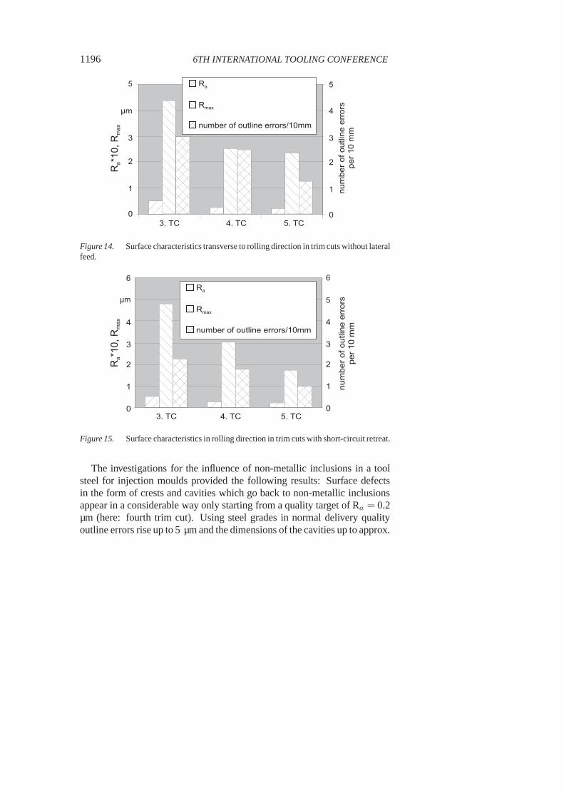
Figure 14. Surface characteristics transverse to rolling direction in trim cuts without lateralfeed.
numb
er of
outlin
e erro
rspe
r 10 m
m
0
1
2
3
4
µ m
6
3 . T C 4 . T C 5 . T C
R a
R m a x
n u m b e r o f o u t l i n e e r r o r s / 1 0 m m
0
1
2
3
4
5
6
R a*10
, Rma
x
Figure 15. Surface characteristics in rolling direction in trim cuts with short-circuit retreat.
The investigations for the influence of non-metallic inclusions in a toolsteel for injection moulds provided the following results:Surface defectsin the form of crests and cavities which go back to non-metallic inclusionsappear in a considerable way only starting from a quality target of Ra = 0.2µm (here: fourth trim cut). Using steel grades in normal delivery qualityoutline errors rise up to 5 µm and the dimensions of the cavities up to approx.
Influence of Non-Metallic Inclusions in Super-Finish Wire Cutting 1197
numb
er of
outlin
e erro
rspe
r 10 m
m
0
1
2
3
4
µ m
6
3 . T C 4 . T C 5 . T C
R a
R m a x
n u m b e r o f o u t l i n e e r r o r s / 1 0 m m
0
1
2
3
4
5
6R a
*10, R
max
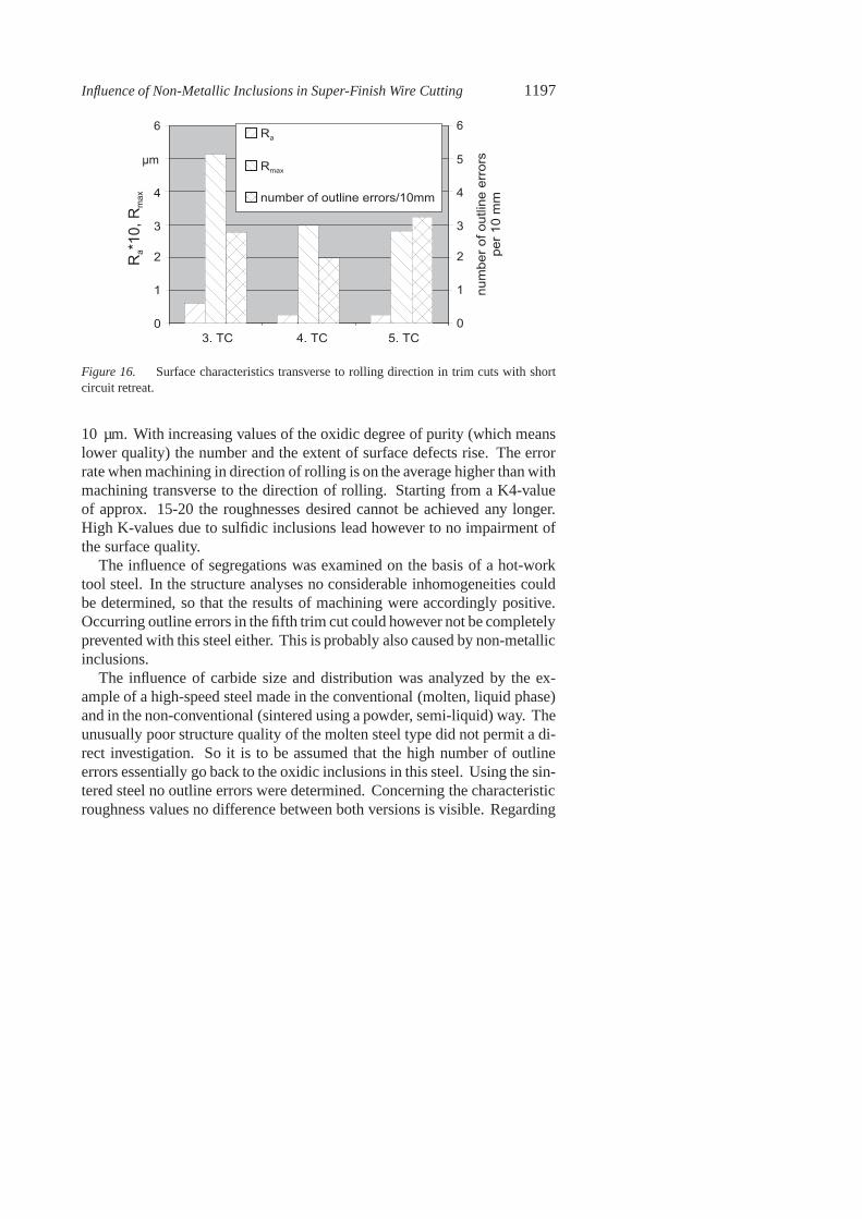
Figure 16. Surface characteristics transverse to rolling direction in trim cuts with shortcircuit retreat.
10 µm. With increasing values of the oxidic degree of purity (which meanslower quality) the number and the extent of surface defects rise. The errorrate when machining in direction of rolling is on the averagehigher than withmachining transverse to the direction of rolling. Startingfrom a K4-valueof approx. 15-20 the roughnesses desired cannot be achievedany longer.High K-values due to sulfidic inclusions lead however to no impairment ofthe surface quality.
The influence of segregations was examined on the basis of a hot-worktool steel. In the structure analyses no considerable inhomogeneities couldbe determined, so that the results of machining were accordingly positive.Occurring outline errors in the fifth trim cut could however not be completelyprevented with this steel either. This is probably also caused by non-metallicinclusions.
The influence of carbide size and distribution was analyzed by the ex-ample of a high-speed steel made in the conventional (molten, liquid phase)and in the non-conventional (sintered using a powder, semi-liquid) way. Theunusually poor structure quality of the molten steel type did not permit a di-rect investigation. So it is to be assumed that the high number of outlineerrors essentially go back to the oxidic inclusions in this steel. Using the sin-tered steel no outline errors were determined. Concerning the characteristicroughness values no difference between both versions is visible. Regarding

1198 6TH INTERNATIONAL TOOLING CONFERENCE
super-finish wire cutting with highest requests concerningsurface qualitytherefore preference is to be given to the sintered version.A variation of thetechnological parameters when cutting a load of rolled ingot bottom scrapiron of the material 40CrMnMoS8-6 (40CrMnMo8-6) showed that by mod-ification of the machining strategy no improvement of the outline accuracycould be achieved. The strategy "short-circuit retreat" even showed a degra-dation of the outline accuracy with machining transverse tothe direction ofrolling.
Altogether the investigations showed that material-dependent impairmentsof the surface quality within the extreme finishing area cannot be excluded.The extent of the outline deviations is limited with today’sdelivery quali-ties usually to the µm-area. Tool construction materials manufactured bysintering prove as favourable.
REFERENCES
[1] R. SIEGEL : Funkenerosives Feinstschneiden – Verfahrenseinflüsse auf dieOberflächen- und Randzonenausbildung. Dissertation RWTH Aachen 1994
[2] W. KONIG and R. SIEGEL, : Funkenerosives Feinstschneiden – Randzonenausbildungund Dauerfestigkeit. dima, 10/93, S. 29-34
[3] T. IKAI and K. HASHIGUCHI , K.: Heat Input for Crater Formation in EDM. Inter-national Symposium for Electromachining (ISEM XI), Lausanne, 17.-21.04.1995 (mitVortragshandbuch)
[4] K. ALBINSKI, K. MUSIOL, A. MIERNIKIEWICZ and S. LABUZ, : Plasma Temper-ature in Electro Discharge Machining. International Symposium for Electromachining(ISEM XI), Lausanne, 17.-21.04.1995 (mit Vortragshandbuch)
[5] J. STEINER, : Stahlauswahl für Werkzeuge und die Polierbarkeit der Stähle. Vortraganläßlich des Seminars "Erodieren, Polieren, Ätzen und Beschichten von Oberflächenin Werkzeugen für die Kunststoff- verarbeitung." Süddeutsches Kunststoffzentrum, 15.-16.09.1992, Würzburg
[6] F. RAKOSKI,: Nichtmetallische Einschlüsse in Stählen.Stahl und Eisen, 144 (1994) 7,S. 71-77
[7] DIN 50 602: „Mikroskopische Prüfung von Edelstählen aufnichtmetallische Ein-schlüsse mit Bildreihen". Sept. 1985, Beuth Verlag GmbH, Berlin
[8] Stahl-Eisen-Prüfblatt 1614 des Vereins Deutscher Eisenhüttenleute: „MikroskopischePrüfung von Warmarbeitsstählen". 1. Ausgabe, Sept. 1996, Verlag Stahleisen GmbH,Düsseldorf