Embed Size (px)
Citation preview

Influence of the Third Harmonic Module on the Beam Size
Maria KuhnUniversity of Hamburg
Bachelor Thesis Presentation
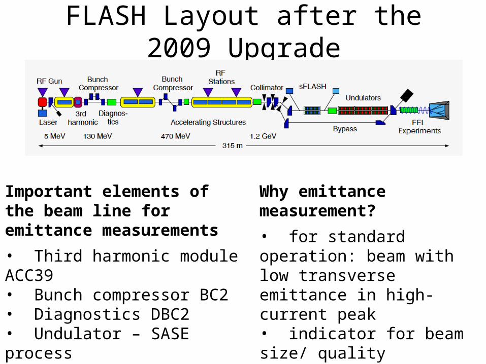
FLASH Layout after the 2009 Upgrade
Important elements of the beam line for emittance measurements
• Third harmonic module ACC39• Bunch compressor BC2• Diagnostics DBC2• Undulator – SASE process
Why emittance measurement?
• for standard operation: beam with low transverse emittance in high-current peak • indicator for beam size/ quality• we determine the projected transverse emittance
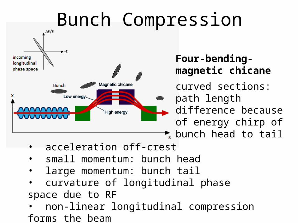
Bunch Compression
Four-bending-magnetic chicane
curved sections: path length difference because of energy chirp of bunch head to tail
• acceleration off-crest• small momentum: bunch head• large momentum: bunch tail• curvature of longitudinal phase space due to RF• non-linear longitudinal compression forms the beam• solution: third harmonic system
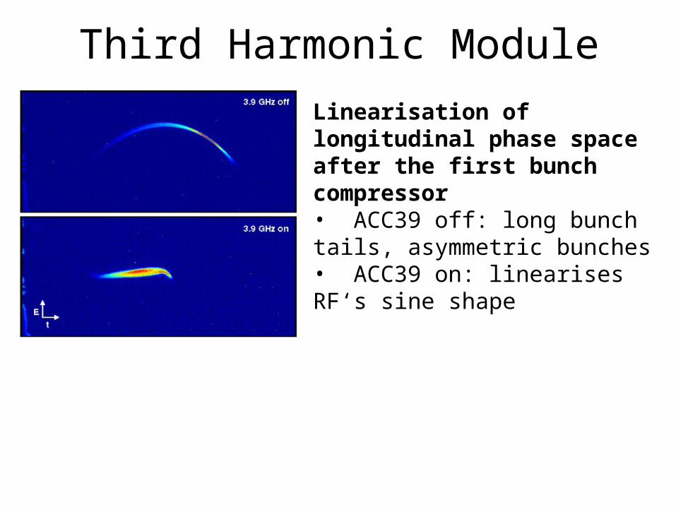
Third Harmonic ModuleLinearisation of longitudinal phase space after the first bunch compressor• ACC39 off: long bunch tails, asymmetric bunches• ACC39 on: linearises RF‘s sine shape
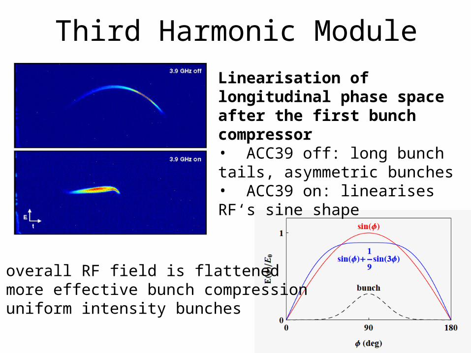
Third Harmonic ModuleLinearisation of longitudinal phase space after the first bunch compressor• ACC39 off: long bunch tails, asymmetric bunches• ACC39 on: linearises RF‘s sine shape
overall RF field is flattened more effective bunch compression uniform intensity bunches
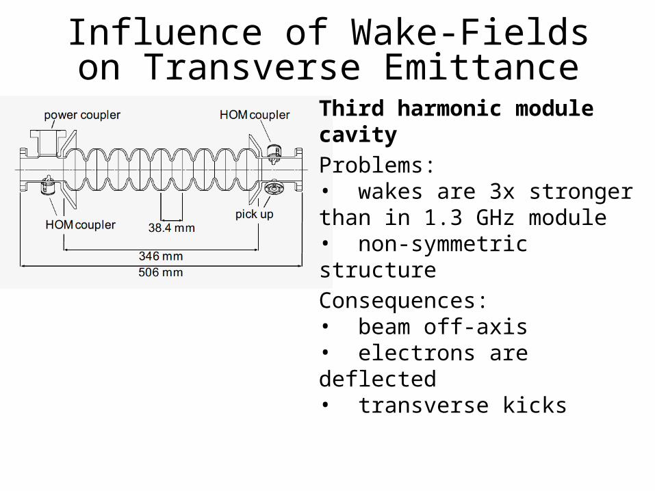
Third harmonic module cavityProblems:• wakes are 3x stronger than in 1.3 GHz module• non-symmetric structureConsequences:• beam off-axis• electrons are deflected• transverse kicks
Influence of Wake-Fields on Transverse Emittance
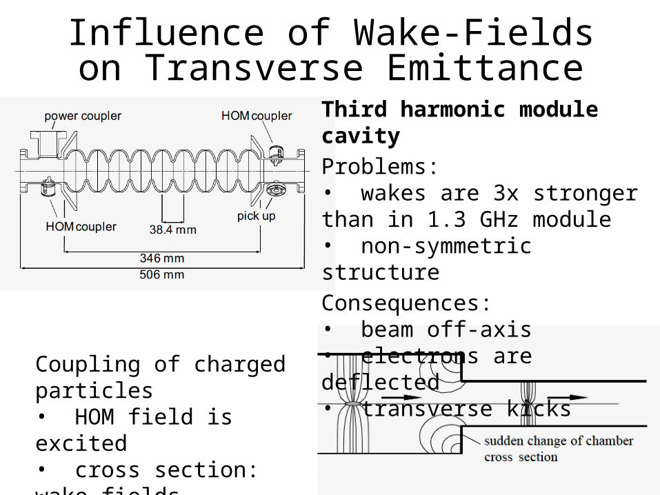
Influence of Wake-Fields on Transverse Emittance
Third harmonic module cavityProblems:• wakes are 3x stronger than in 1.3 GHz module• non-symmetric structureConsequences:• beam off-axis• electrons are deflected• transverse kicks Coupling of charged particles
• HOM field is excited• cross section: wake-fields• projected emittance grows
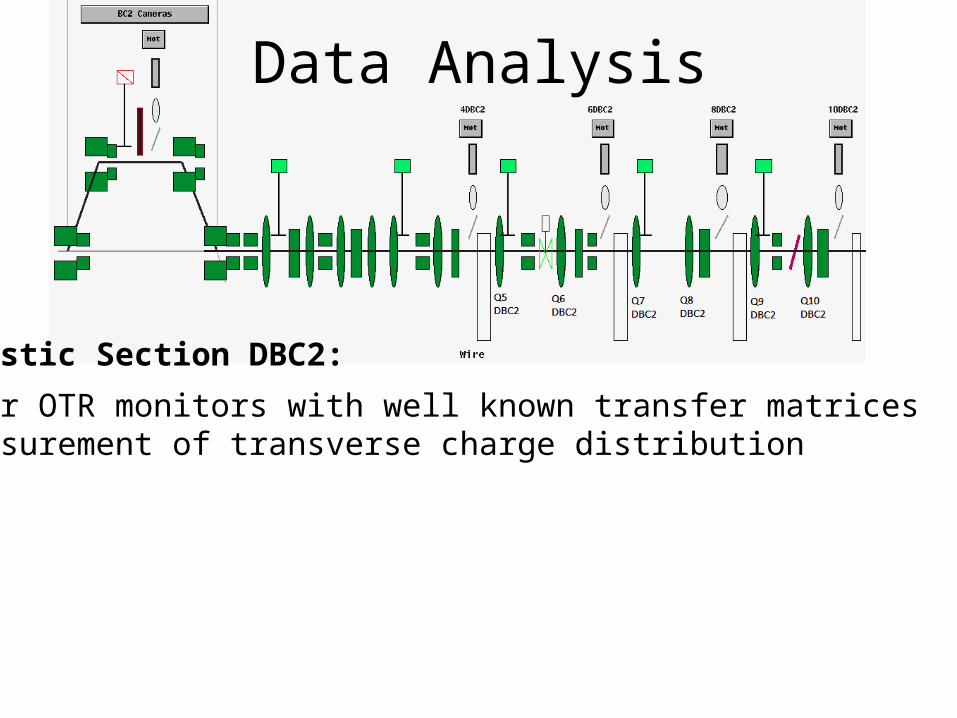
Data Analysis
Diagnostic Section DBC2:
• four OTR monitors with well known transfer matrices• measurement of transverse charge distribution
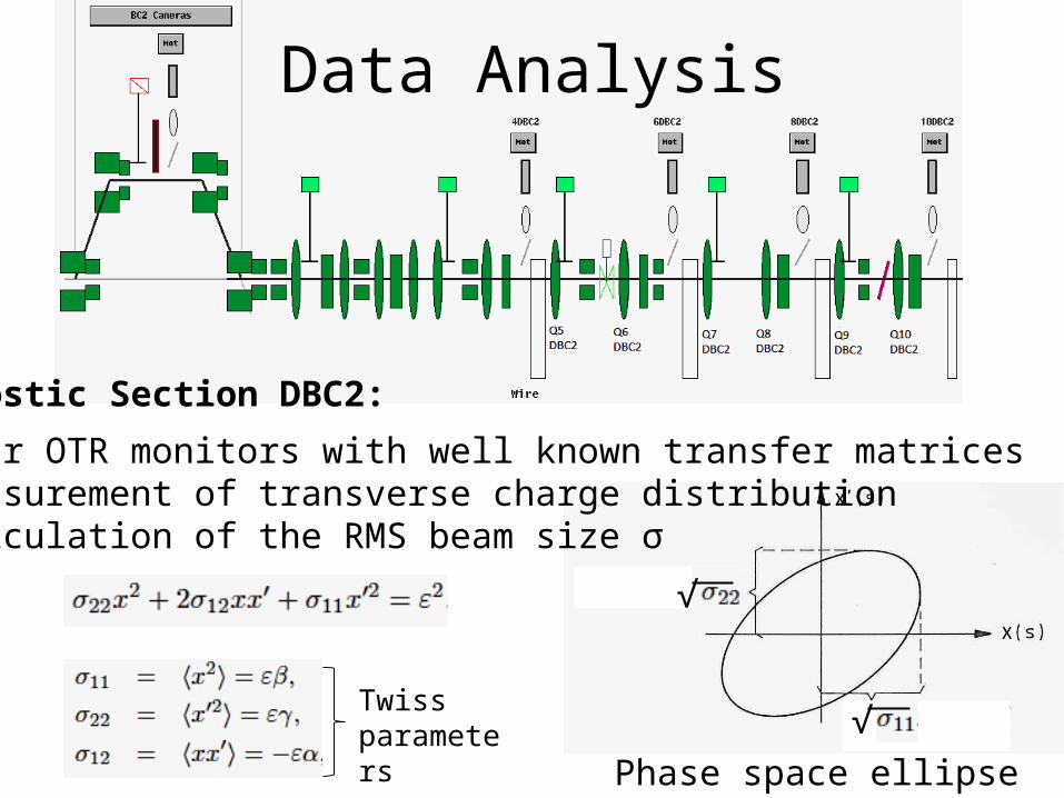
Data Analysis
Diagnostic Section DBC2:
• four OTR monitors with well known transfer matrices• measurement of transverse charge distribution• calculation of the RMS beam size σ
Phase space ellipse
Twiss parameters
√
√
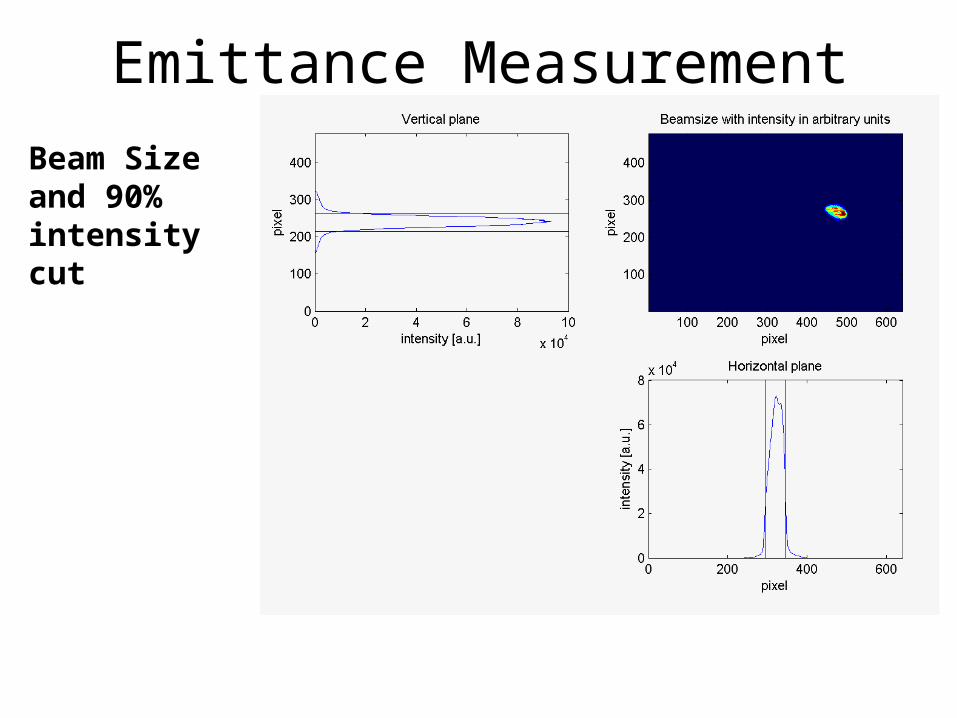
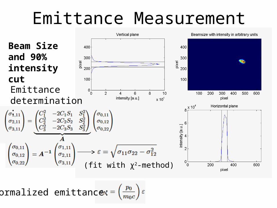
Emittance MeasurementBeam Size and 90% intensity cut
Emittance MeasurementBeam Size and 90% intensity cut
Normalized emittance:
Emittance determination:
(fit with χ2-method)
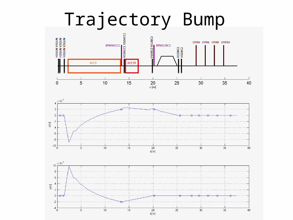
Trajectory Bump
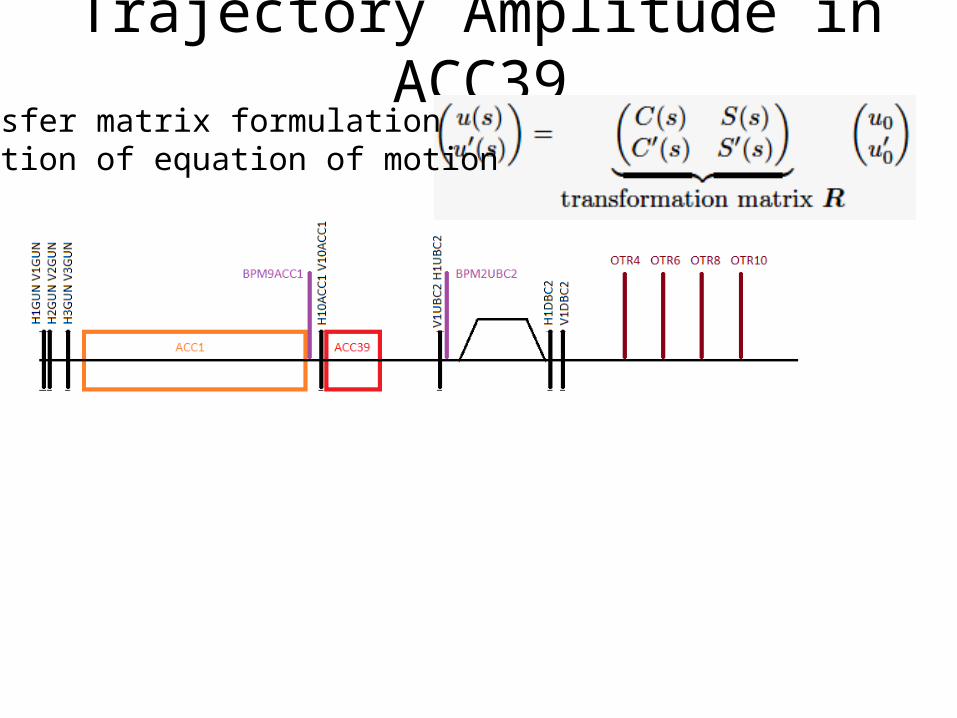
Trajectory Amplitude in ACC39Transfer matrix formulationSolution of equation of motion
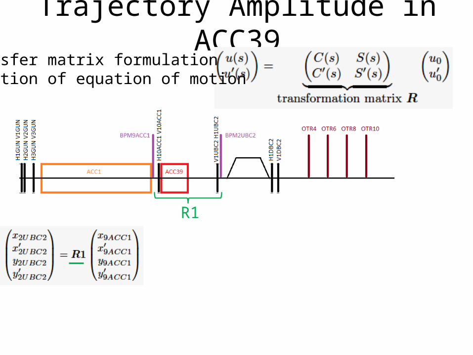
Trajectory Amplitude in ACC39Transfer matrix formulationSolution of equation of motion
R1
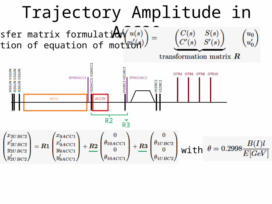
Trajectory Amplitude in ACC39Transfer matrix formulationSolution of equation of motion
with
R2R3
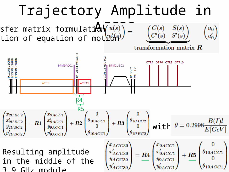
Trajectory Amplitude in ACC39Transfer matrix formulationSolution of equation of motion
Resulting amplitude in the middle of the 3.9 GHz module
with
R4
R5
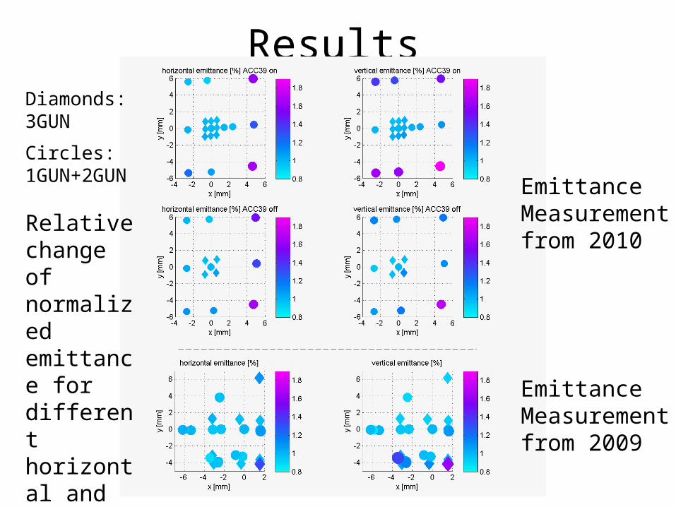
Results
Emittance Measurement from 2010
Emittance Measurement from 2009
Diamonds: 3GUN
Circles: 1GUN+2GUN
Relative change of normalized emittance for different horizontal and vertical bump amplitudes
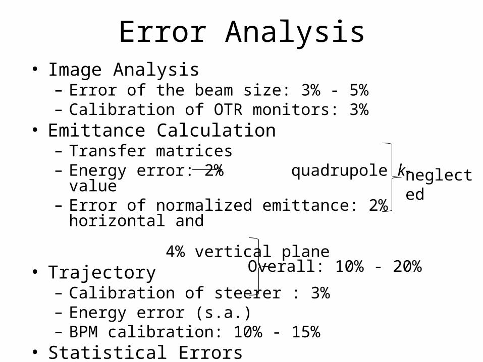
Error Analysis• Image Analysis– Error of the beam size: 3% - 5%– Calibration of OTR monitors: 3%
• Emittance Calculation– Transfer matrices– Energy error: 2% quadrupole k-value– Error of normalized emittance: 2% horizontal and
4% vertical plane• Trajectory– Calibration of steerer : 3%– Energy error (s.a.)– BPM calibration: 10% - 15%
• Statistical Errors– Beam size (CCD camera) < 5%
Overall: 10% - 20%
neglected
Conclusion
• The third harmonic module linearises the longitudinal phase space
• For standard operation the new system does not alter the projected transverse emittance
• The influence of wake-fields from the ACC39 cavities can be neglected
Results II
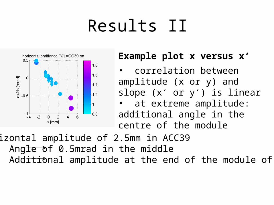
Example plot x versus x‘
• correlation between amplitude (x or y) and slope (x‘ or y‘) is linear• at extreme amplitude: additional angle in the centre of the module
Horizontal amplitude of 2.5mm in ACC39Angle of 0.5mrad in the middle Additional amplitude at the end of the module of 0.5mm