Embed Size (px)
Citation preview
Influence of the slopes of the specimen grating surface on out-of-plane displacements measured by moire interferometry James McKelvie and Krzysztof Patorski
James McKelvie is with University of Strathclyde, Department of Mechanical & Offshore Engineering, Glasgow G1 1XJ, Scotland, U.K., and Krzysztof Patorski is with Warsaw University of Technology, Institute of Design of Precise & Optical Instruments, 02-525 Warsaw, Poland. Received 16 February 1988. 0003-6935/88/224603-03$02.00/0. © 1988 Optical Society of America. Moire interferometry is a high-sensitivity technique for
whole-field mapping of in-plane displacements of deformed objects. A reflective-type diffraction grating fixed to the specimen under study is symmetrically illuminated by a pair of coherent plane wavefronts. Two mutually conjugate grating diffraction orders propagate along the specimen normal and form an interference pattern which represents the map of in-plane displacements of an object under load. The detailed description of the method can be found, for example, in the extended review paper by Post.1
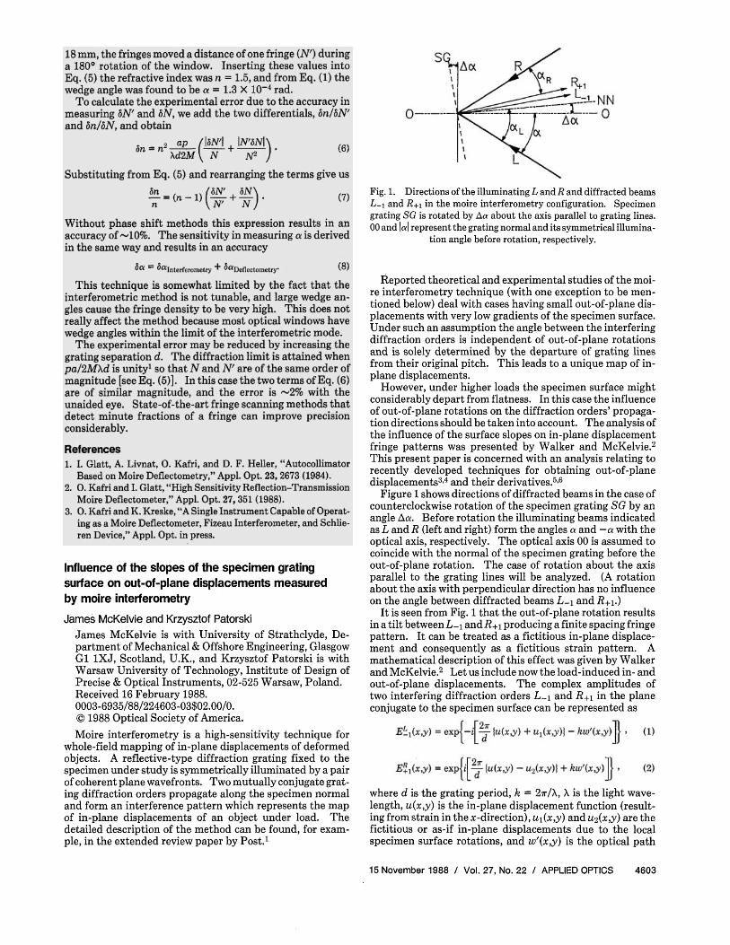
Fig. 1. Directions of the illuminating L and R and diffracted beams L-1 and R+1 in the moire interferometry configuration. Specimen grating SG is rotated by Δα about the axis parallel to grating lines. 00 and |α| represent the grating normal and its symmetrical illumina
tion angle before rotation, respectively.
Reported theoretical and experimental studies of the moire interferometry technique (with one exception to be mentioned below) deal with cases having small out-of-plane displacements with very low gradients of the specimen surface. Under such an assumption the angle between the interfering diffraction orders is independent of out-of-plane rotations and is solely determined by the departure of grating lines from their original pitch. This leads to a unique map of in-plane displacements.
However, under higher loads the specimen surface might considerably depart from flatness. In this case the influence of out-of-plane rotations on the diffraction orders' propagation directions should be taken into account. The analysis of the influence of the surface slopes on in-plane displacement fringe patterns was presented by Walker and McKelvie.2
This present paper is concerned with an analysis relating to recently developed techniques for obtaining out-of-plane displacements3,4 and their derivatives.5,6
Figure 1 shows directions of diffracted beams in the case of counterclockwise rotation of the specimen grating SG by an angle Δα. Before rotation the illuminating beams indicated as L and R (left and right) form the angles a and - a with the optical axis, respectively. The optical axis 00 is assumed to coincide with the normal of the specimen grating before the out-of-plane rotation. The case of rotation about the axis parallel to the grating lines will be analyzed. (A rotation about the axis with perpendicular direction has no influence on the angle between diffracted beams L-1 and R+1.)
It is seen from Fig. 1 that the out-of-plane rotation results in a tilt between L-1 and R+1 producing a finite spacing fringe pattern. It can be treated as a fictitious in-plane displacement and consequently as a fictitious strain pattern. A mathematical description of this effect was given by Walker and McKelvie.2 Let us include now the load-induced in- and out-of-plane displacements. The complex amplitudes of two interfering diffraction orders L-1 and R+1 in the plane conjugate to the specimen surface can be represented as
where d is the grating period, k = 2π/λ, λ is the light wavelength, u(x,y) is the in-plane displacement function (resulting from strain in the x-direction), U1(x,y) and u2(x,y) are the fictitious or as-if in-plane displacements due to the local specimen surface rotations, and w'(x,y) is the optical path
15 November 1988 / Vol. 27, No. 22 / APPLIED OPTICS 4603
methods generating the derivative of out-of-plane displacements.6-9 Introducing Eqs. (1) and (2) into the mathematics of those methods we obtain the corresponding intensity
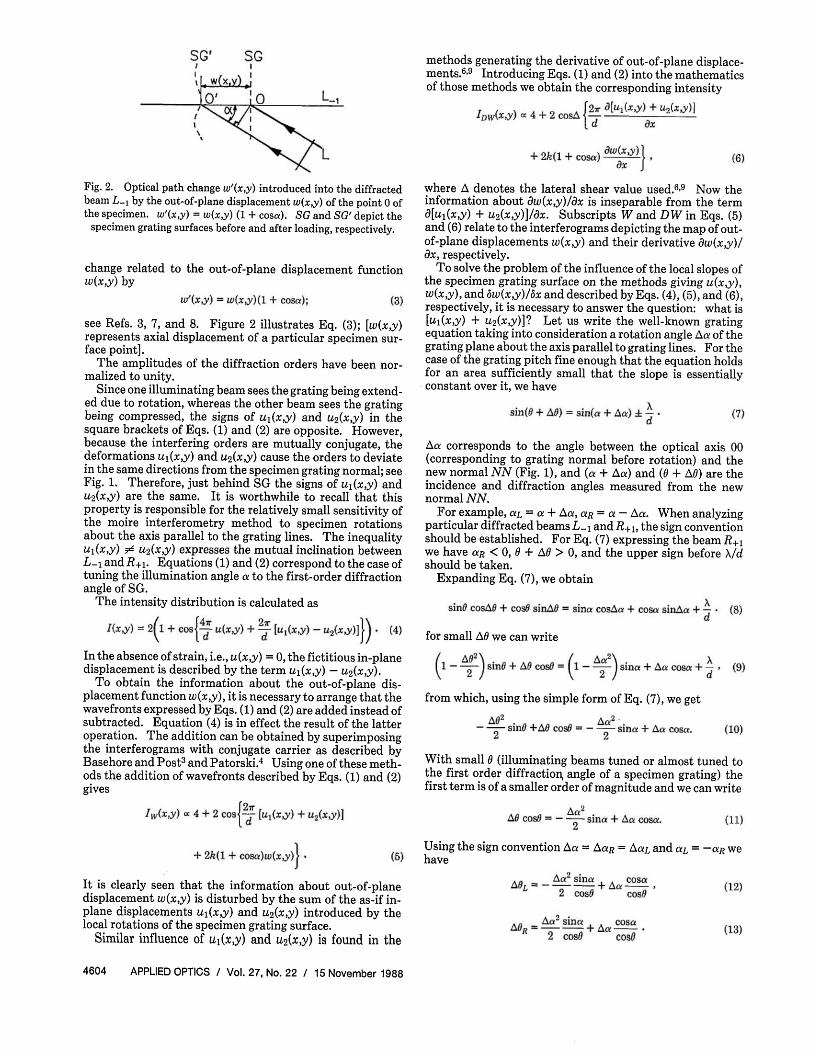
Fig. 2. Optical path change w'(x,y) introduced into the diffracted beam L-1 by the out-of-plane displacement w(x,y) of the point 0 of the specimen. w'(x,y) = w(x,y) (1 + cosα). SG and SG' depict the
specimen grating surfaces before and after loading, respectively.
change related to the out-of-plane displacement function w(x,y) by
see Refs. 3, 7, and 8. Figure 2 illustrates Eq. (3); [w(x,y) represents axial displacement of a particular specimen surface point].
The amplitudes of the diffraction orders have been normalized to unity.
Since one illuminating beam sees the grating being extended due to rotation, whereas the other beam sees the grating being compressed, the signs of u1(x,y) and u2(x,y) in the square brackets of Eqs. (1) and (2) are opposite. However, because the interfering orders are mutually conjugate, the deformations U1(x,y) and u2(x,y) cause the orders to deviate in the same directions from the specimen grating normal; see Fig. 1. Therefore, just behind SG the signs of U1(x,y) and u2(x,y) are the same. It is worthwhile to recall that this property is responsible for the relatively small sensitivity of the moire interferometry method to specimen rotations about the axis parallel to the grating lines. The inequality U1(x,y) ≠ u2(x,y) expresses the mutual inclination between L-1 and R+1. Equations (1) and (2) correspond to the case of tuning the illumination angle a to the first-order diffraction angle of SG.
The intensity distribution is calculated as
In the absence of strain, i.e., u(x,y) = 0, the fictitious in-plane displacement is described by the term u1(x,y) - u2(x,y).
To obtain the information about the out-of-plane displacement function w(x,y), it is necessary to arrange that the wavefronts expressed by Eqs. (1) and (2) are added instead of subtracted. Equation (4) is in effect the result of the latter operation. The addition can be obtained by superimposing the interferograms with conjugate carrier as described by Basehore and Post3 and Patorski.4 Using one of these methods the addition of wavefronts described by Eqs. (1) and (2) gives
It is clearly seen that the information about out-of-plane displacement w(x,y) is disturbed by the sum of the as-if in-plane displacements u1(x,y) and u2(x,y) introduced by the local rotations of the specimen grating surface.
Similar influence of u1(x,y) and u2(x,y) is found in the
where Δ denotes the lateral shear value used.6-9 Now the information about dw{x,y)/dx is inseparable from the term [u1(x,y) + u2(x,y)]/ x. Subscripts W and DW in Eqs. (5)
and (6) relate to the interferograms depicting the map of out-of-plane displacements w(x,y) and their derivative dw(x,y)/ dx, respectively.
To solve the problem of the influence of the local slopes of the specimen grating surface on the methods giving u(x,y), w(x,y), and δw(x,y)/δx and described by Eqs. (4), (5), and (6), respectively, it is necessary to answer the question: what is [u1(x,y) + u2(x,y)]? Let us write the well-known grating equation taking into consideration a rotation angle Δα of the grating plane about the axis parallel to grating lines. For the case of the grating pitch fine enough that the equation holds for an area sufficiently small that the slope is essentially constant over it, we have
Δα corresponds to the angle between the optical axis 00 (corresponding to grating normal before rotation) and the new normal NN (Fig. 1), and (a + Δα) and (θ + Δθ) are the incidence and diffraction angles measured from the new normal NN.
For example, αL = α + Δα, αR = a - Δα. When analyzing particular diffracted beams L-1 and R+1, the sign convention should be established. For Eq. (7) expressing the beam R+1 we have αR < 0, θ + Δθ > 0, and the upper sign before λ/d should be taken.
Expanding Eq. (7), we obtain
for small Δ0 we can write
from which, using the simple form of Eq. (7), we get
With small 0 (illuminating beams tuned or almost tuned to the first order diffraction, angle of a specimen grating) the first term is of a smaller order of magnitude and we can write
Using the sign convention a = ΔαR = ΔαL and aL = -aR we have
4604 APPLIED OPTICS / Vol. 27, No. 2 2 / 1 5 November 1988
These are the changes in the propagation directions of diffracted beams caused by the out-of-plane grating rotation Δα. To relate them to u1(x,y) and u2(x,y), it is necessary to note that the phase change in the diffracted beam satisfies the following relationship:
with the integral on the right-hand side describing the change of optical path. Now with Eqs. (12) and (13) we have
We obtain subsequently
The fictitious strain due to rotation with θ = 0 is
The necessity of introducing the coefficient 1/2 follows from Eq. (4) and the comparison of the coefficients of u(x,y) and u1(x,y) - u2(x,y). The result is the same as the one developed in the paper by Walker and McKelvie.2
The apparent out-of-plane displacement, Eq. (5), is
and its spatial derivative is
Since Δα = w(x,y)/ x we have from Eq. (6)
The intensity pattern is thus still seen to represent contours of constant [ w(x,y)]/ x, but there is a modification to be made to the fringe interval value. For a particular moire interferometry configuration the parameters a and θ are known. Therefore, the sensitivity can be completely specified. It is higher by the term (cosα)/(cosθ) when compared with the case in which the effect of the as-if displacement is omitted.
It is hoped that an experimental investigation of the formula derived will be reported in a separate paper. Additionally, the search for an experimental technique enabling the separation of the true in-plane, as-if in-plane, and out-of-plane plane displacements will be continued.
References 1. D. Post, "Moire Interferometry," in SEM Handbook on Experi
mental Mechanics, A. S. Kobayashi, Ed. (Prentice-Hall, Engle-wood Cliffs, NJ, 1986).
2. C. A. Walker and J. McKelvie, "A Practical Multiplied Moire System," Exp. Mec. 18,316 (1978).
3. M. L. Basehore and D. Post, "Displacement Fields (U,W) Obtained Simultaneously by Moire Interferometry," Appl. Opt. 21, 2558 (1982).
4. K. Patorski, "A Method for Obtaining Out-of-Plane Displacements by Moire Interferometry," Opt. Commun. 60, 128 (1986).
5. L. Pirodda, "Strain Analysis by Grating Interferometry," Opt. Lasers Eng. 5, 7 (1984).
6. K. Patorski, "Generation of the Derivative of Out-of-Plane Displacements Using Conjugate Shear and Moire Interferometry," Appl. Opt. 25, 3146 (1986).
7. K. Matsumoto and M. Takashima, "Improvement on Moire Technique of In-Plane Deformation Measurements," Appl. Opt. 12, 858 (1973).
8. M. L. Basehore and D. Post, "Moire Method for In-Plane and Out-of-Plane Displacement Measurements," Exp. Mech. 21, 331 (1981).
9. K. Patorski and M. Kujawinska, "Optical Differentiation of Displacement Patterns Using Moire Interferometry," Appl. Opt. 24, 3041 (1985).
15 November 1988 / Vol. 27, No. 22 / APPLIED OPTICS 4605


![APPROVED - Virginia Tech...of these advantages, moire technique is very unique and significantly advanced [21]. Moire interferometry is extremely powerful for shear strain measurement](https://img.pdfslide.us/doc/110x75/60c116ee1f993f1dd564c5ee/approved-virginia-tech-of-these-advantages-moire-technique-is-very-unique.jpg)