Embed Size (px)
Citation preview

649
Abstract
A subway train-steel spring floating slab track-tunnel coupling
dynamic model, considering short and middle-long wavelength
random track irregularities, and longitudinal connection between
adjacent slabs of steel spring floating slab track, was developed.
And the influence of slab length on dynamic characteristics of the
system under different track conditions and train speeds are theo-
retically studied. The calculated results show: (1) In general, the
acceleration of each component of the coupled system decreases
with the increase of slab length under the perfectly smooth track
condition; (2) Slab length has different influence laws on accelera-
tion of each component of subway train-steel spring floating slab
track-tunnel coupled system under random irregularity of track
condition. The lower the dominant frequency distribution of vibra-
tion acceleration is, the higher influence slab length has; (3) With
the increase of slab length, the force of rail, fastener and steel
spring also decreases significantly, which helps to lengthen the
service life of these components; (4) With the increase of slab
length, the longitudinal bending moment of slab increases sharply
at first, then it begins to drop slightly. When slab length exceeds
the distance between two bogies of a vehicle, the longitudinal
bending moment of slab changes little; (5) Slab length has signifi-
cant influence on the dynamic force and displacement of the cou-
pled system when train speed is higher.
Keywords
Steel spring; floating slab track; slab length; subway train; dynam-
ic characteristics; tunnel.
Influence of slab length on dynamic characteristics of subway
train-steel spring floating slab track-tunnel coupled system
1 INTRODUCTION
Urban rail transit has been widely used owing to its large capacity, punctuality, safety, reliability,
and comfortable passenger environment. However, this mode of transportation is also accompanied
by an environmental vibration problem due to the operation of subway trains. A variety of vibra-
Qing-yuan Xu a,b,c
Bin Yan a
Ping Lou a,b,c*
Xiao-lin Zhoua
a School of Civil Engineering, Railway
Campus, Central South University, Chang-
sha, Hunan 410075, China. bKey Laboratory of Heavy Railway Engi-
neering Structure of Education Ministry,
Railway Campus, Central South Universi-
ty, Hunan 410075, China. c Collaborative Innovation Center of Rail
Safety, Central South University, Hunan
410075, China.
Corresponding author email:
http://dx.doi.org/10.1590/1679-78251327
Received 05.05.2014
In revised form 22.09.2014
Accepted 22.09.2014
Available online 13.10.2014

650 Q.-Y. Xu et al. / Influence of slab length on dynamic characteristics of subway train-steel spring floating slab track-tunnel coupled system
Latin American Journal of Solids and Structures 12 (2015) 649-674
tion-reduction measures have been undertaken during the design and construction of subway lines.
Among them, the floating slab track (FST) structure has been widely used for its excellent vibra-
tion-reduction capability. Many scholars have conducted extensive research on the FST structure
and its impact on environmental vibration.
Hussein and Hunt (2006) studied the dynamic characteristics of a continuous FST on a rigid
foundation with moving harmonic loads by the Fourier transform method, and found little differ-
ence between static and dynamic calculation results of the continuous FST structure at normal
train speeds if the track was perfectly smooth. Using the semi-analytical pipe-in-pipe (PiP) three-
dimensional (3D) model to simulate the interaction between a tunnel and a semi-infinite soil foun-
dation, Hussein and Hunt (2009) compared the displacements at the free surface under moving
harmonic loads for a track with a discontinuous slab to those for a track with a continuous floating
slab.
By means of a 3D numerical model for the prediction of railway induced vibrations that fully ac-
counts for the interaction among the train, the track and the soil, Lombaert et al. (2006) dealt with
the effectiveness of a FST for the control of ground-borne vibrations generated by rail transporta-
tion systems.
Gupta et al. (2007) compared the semi-analytical PiP 3D model with the coupled periodic finite
element-boundary element model, for predicting vibrations due to underground railway traffic, and
the effect of coupling a floating slab to the tunnel–soil system is studied with both models by cal-
culating the insertion gain. With the coupled periodic finite element-boundary element model, Gup-
ta et al. (2008) studied the effect of environmental vibration induced by the metro traffic of Beijing
subway line 4 on the equipment of the physics laboratory of Beijing University; Gupta and
Degrande (2010) used the model to assess the vibration isolation efficiency of continuous and dis-
continuous floating slab tracks.
Kuo et al. (2008) developed a vehicle-FST coupling dynamic model on a rigid foundation, and
studied the influence of train speed, floating slab stiffness, floating slab mass, and fastener stiffness
on the dynamic characteristics of the FST structure.
Taking the nonlinear suspension stiffness of the vehicle into account, Müller et al. (2008) devel-
oped a train-FST-tunnel-soil coupling dynamic model, and studied the influence of nonlinear vehicle
suspension stiffness and equivalent linear vehicle suspension stiffness on the dynamic characteristics
of the coupled system.
Auersch (2012) analyzed the dynamics of slab track and FST for a great variety of track and soil
parameters by multibeam models for the track and by integration in the wave-number domain for
the soil, which is modeled as a layered half-space. The reduction effects of the FST are examined
and compared with the reduction of the ground vibration away from the railway line.
In order to protect the cultural receptors along the Athens metro extension to Piraeus due to
ground borne noise and vibration, Vogiatzis (2012) numerically predicted the ground borne noise
and vibration levels for sensitive buildings along the metro extension with standard STEDEF track
and FST respectively, and compared the prediction results with the allowable ground borne noise
and vibration level. The installation of floating slab in some special sections was suggested.
Recently, Hung et al. (2013) incorporated the railway irregularity and dynamic properties of the
moving train in a 2.5D finite/infinite-element prediction model to study the effect of railway irregu-
larity on soil vibrations due to moving trains.

Q.-Y. Xu et al. / Influence of slab length on dynamic characteristics of subway train-steel spring floating slab track-tunnel coupled system 651
Latin American Journal of Solids and Structures 12 (2015) 649-674
In addition to theoretical researches, numerous experimental studies have also been performed
regarding the dynamic characteristics of FST and their effects on environmental vibration. At the
Laboratory of Track Vibration Abatement and Control, which is an underground facility of Beijing
Jiaotong University in China, Ding et al. (2011) applied harmonic loads with frequencies of 5-16 Hz
on FST with different stiffness and supporting spacing, and measured the vibration responses of the
FST, the underground tunnel, and the free ground surface at distances 0-80 m away from the un-
derground tunnel. Saurenman and Phillips (2006) conducted an environmental vibration test near
one section of a FST of the BART rapid line. Cox et al. (2006) built a 2.5-meter-long full-scale FST
model in an indoor laboratory, applied harmonic loads of different frequencies on the rail, and
measured the vibration characteristics of the FST structure.
As can be seen from the above description, many theoretical and experimental research efforts
have been made on the dynamic characteristics of FST and their influence on environmental vibra-
tion. However, few studies have been made on the influence of slab length, which is a key technical
parameter of FST structure, on the dynamic characteristics of the subway train-FST-tunnel-soil
coupled system.
The remaining of this paper is organized as follows. At first, a subway train-steel spring floating
slab track (SSFST)-tunnel coupling dynamic model that considers both short and middle to long
wavelength random track irregularities, the longitudinal connection between adjacent slabs of
SSFST and the coupling effect of the entire system is developed. And then corresponding computer
programs are compiled to study the influence of slab length on the dynamic characteristics of the
coupled system under different track irregularity conditions and train speeds.
2 COUPLING DYNAMIC MODEL
A schematic describing the dynamic model for a subway train traveling on a FST in a tunnel at a
constant speed v along the longitudinal direction is shown in Figure 1.
V
Secondarysuspension
Primarysuspension
Bogie
Wheel
Car body
Rail
SlabFastener
Steel
spring
TunnelWinkler foundation
of tunnel Figure 1: Schematic of the coupling dynamic model.

652 Q.-Y. Xu et al. / Influence of slab length on dynamic characteristics of subway train-steel spring floating slab track-tunnel coupled system
Latin American Journal of Solids and Structures 12 (2015) 649-674
The model consists of four sub-models, namely, the subway train, the SSFST-tunnel, wheel-
rail interaction, and track irregularity sub-models. They are explained as follows.
2.1 Subway train sub-model
As shown in Figure 1, the subway train sub-model consists of a series of identical four-wheel vehi-
cles. Each vehicle in the train is modeled as a mass-spring-damper system consisting of a car body
with vertical and pitch motions, two bogie frames with vertical and pitch motions, four wheels
with vertical motions, and two-stage suspensions. Therefore, each vehicle has 10 degrees of free-
dom (DOFs).
2.2 SSFST-tunnel sub-model
The SSFST-tunnel is a spatial structure. The sub-model can reflect the spatial dynamic characte-
ristics of a SSFST-tunnel-soil system well using volume elements with a small mesh size to simu-
late the slab, tunnel, and surrounding soil. However, calculations are very time-consuming if vo-
lume elements with a small mesh size are used, especially in this study. The reasons are as fo-
llows.
Firstly, as shown in Figure 2, to eliminate the influence of boundary conditions, more than 20
m of track to the left and right sides upon which the train does not travel must be included. In
addition, the actual length of the train (6 vehicles, 114 m) and a long moving distance of train
(330 m) are considered. Therefore, the total length of the dynamic model is more than 500 m,
which results in a large number of DOFs to simulate the coupled system.
Length of model(502.5-540m,integral multiple of slab length,different slab length case has different value)
Moving distance of train(330m)
Initial position of train End position of train
114m 330m36m 22.5-60m
Different slab length
case has different value
Figure 2: Layout of train and track.
Secondly, to appropriately include the influence of short wavelength random track irregularity,
the train moving distance during each time step should be less than half of the minimum wave-
length of the track irregularity considered. As a result, a very small time step is required in the
simulation.
Finally, the dynamic force of the components of the FST is very sensitive to the finite element
size. To obtain a reasonable value for the dynamic force, the finite element mesh size should be

Q.-Y. Xu et al. / Influence of slab length on dynamic characteristics of subway train-steel spring floating slab track-tunnel coupled system 653
Latin American Journal of Solids and Structures 12 (2015) 649-674
sufficiently small. A small finite element size is also required in this study to reasonably simulate
the continuous support characteristics of the tunnel.
For the reasons given above, it is extremely time-consuming if small mesh size volume ele-
ments are used to simulate the slab, the tunnel, and surrounding soil, and the calculations are not
easily conducted on an ordinary personal computer at present. To reduce the calculation time,
according to reference (Gardien and Stuit, 2003), a long beam supported on a Winkler elastic
foundation is used to model the tunnel. The SSFST-tunnel sub-model is shown in Figure 3.
Winkler foundation of tunnel
Shear hinge
Steel spring
Fastener
Tunnel
Slab
Rail
Figure 3: SSFST-tunnel dynamic model.
The rail, slab, and tunnel are simulated by Bernoulli-Euler beam elements, while fasteners
which connect rail and slab, steel springs which connect slab and tunnel, shear hinges which con-
nect two adjacent slabs, as well as the Winkler foundation of the tunnel are simulated by linear
spring-damper elements.
A sophisticated 3D SSFST-tunnel-soil model (Figure 4) is used to determine the equivalent
stiffness of the Winkler foundation of the tunnel. In the model, the rail is simulated by Bernoulli-
Euler beam elements. The slab, tunnel, soil, and steel spring are simulated by volume elements.
Fasteners and shear hinges are simulated by linear spring-damper elements.
(a) Cross-section graph (b) Enlarged graph
Rail
Fastener
Floating slab
Steel spring
Tunnel
Soil
Figure 4: Sophisticated 3D SSFST-tunnel-soil model.
The procedures used to determine the equivalent stiffness of the Winkler foundation of the
tunnel (Figure 3) are as follows.
(1) Use ANSYS Parametric Design Language to develop the SSFST-tunnel model (Figure 3)
and the sophisticated 3D SSFST-tunnel-soil model (Figure 4).

654 Q.-Y. Xu et al. / Influence of slab length on dynamic characteristics of subway train-steel spring floating slab track-tunnel coupled system
Latin American Journal of Solids and Structures 12 (2015) 649-674
(2) Apply the train load to the sophisticated 3D SSFST-tunnel-soil model (Figure 4), and ob-
tain the maximum vertical displacement y of the tunnel.
(3) Three initial values for the stiffness of the Winkler foundation of the tunnel are assumed.
The value of the first initial stiffness k1 is a small value that is much less than the calculated
equivalent stiffness of the Winkler foundation of the tunnel; the value of the second initial stiff-
ness k2 is a large value that is much larger than the calculated equivalent stiffness of the Winkler
foundation of the tunnel; and the value of the third initial stiffness k3 is the average stiffness of k1
and k2.
(4) Apply the train load to the SSFST-tunnel model (Figure 3) with Winkler foundation stiff-
ness values k1, k2, and k3, and obtain the maximum vertical displacements of the tunnel y1, y2,
and y3, respectively.
(5) Calculate the error between y and y3. If the error between y and y3 is less than 1×10⁻⁹ m,
then the calculated equivalent stiffness of the Winkler foundation of the tunnel is k3. Otherwise,
return to procedure (4) and continue the computation using the bi-section iterative method until
the relative error between y and y3 is less than 1×10⁻⁹ m.
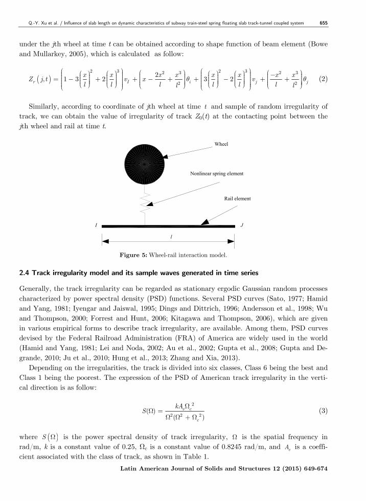
2.3 Wheel-rail interaction model
The wheel-rail interaction model is shown in Figure 5. The interaction between the wheel and the
rail is simulated by the moving nonlinear spring element. When the wheel moves forward, the
contact point between the wheel and the rail changes constantly.
The vertical force between the wheel and rail can be determined according to the Hertz nonli-
near contact theory that considers the track irregularity (Zhai and Cai, 1997; Lei and Noda,
2002) as follow:
3/2
00
0
1 ( ) ( ) ( ) 0 [ ( ) ( ) ( )](t)
( ) ( ) ( ) 00
w rw rj
w r
Z j,t Z j,t Z tZ j,t Z j,t Z tP G
Z j,t Z j,t Z t
− − >− −= − − ≤
(1)
where Pj(t) is the wheel-rail contact force under the jth wheel at time t; G is the wheel-rail con-
tact constant, 0.115 8 2/33.86 10 m/NG R− −= × , R is the wheel radius; Zw(j, t) is the displacement of
the jth wheel at time t, Zr(j, t) is the rail displacement under the jth wheel at time t, and Z0(t) is
the track irregularity under the jth wheel at time t. Zr(j, t) and Z0(t) can be determinted accor-
ding to the coordinate of jth wheel at time t. The detailed procedures to determinte Zr(j, t) and
Z0(t) are as follows:
Assuming that the initial position of the jth wheel of subway train is 0x , and the constant
speed of the subway train is V . Then the coordinate of jth wheel is 0x Vt+ at time t. According
to the coordinate of jth wheel at time t, the rail element number contacting with the jth wheel at
time t, the left node number I of the rail element, the right node number J of the rail element,
and the distance between the rail node I and the contacting point of jth wheel can be determi-
ned (Figure 5). Assuming that the vertical displacement and rotation displacement of rail node I
and node J are Iv , Iθ and Jv , Jθ respectively at time t, the distance between the rail node I
and the contacting point of jth wheel is x , the length of rail element is l . The rail displacement
Q.-Y. Xu et al. / Influence of slab length on dynamic characteristics of subway train-steel spring floating slab track-tunnel coupled system 655
Latin American Journal of Solids and Structures 12 (2015) 649-674
under the jth wheel at time t can be obtained according to shape function of beam element (Bowe
and Mullarkey, 2005), which is calculated as follow:
( )2 3 2 32 3 2 3
2 2
2, 1 3 2 3 2r I i j j
x x x x x x x xZ j t v x v
l l l l l ll lθ θ
− = − + + − + + − + + (2)
Similarly, according to coordinate of jth wheel at time t and sample of random irregularity of
track, we can obtain the value of irregularity of track Z0(t) at the contacting point between the
jth wheel and rail at time t.
Wheel
Nonlinear spring element
Rail element
I J
l
Figure 5: Wheel-rail interaction model.
2.4 Track irregularity model and its sample waves generated in time series
Generally, the track irregularity can be regarded as stationary ergodic Gaussian random processes
characterized by power spectral density (PSD) functions. Several PSD curves (Sato, 1977; Hamid
and Yang, 1981; Iyengar and Jaiswal, 1995; Dings and Dittrich, 1996; Andersson et al., 1998; Wu
and Thompson, 2000; Forrest and Hunt, 2006; Kitagawa and Thompson, 2006), which are given
in various empirical forms to describe track irregularity, are available. Among them, PSD curves
devised by the Federal Railroad Administration (FRA) of America are widely used in the world
(Hamid and Yang, 1981; Lei and Noda, 2002; Au et al., 2002; Gupta et al., 2008; Gupta and De-
grande, 2010; Ju et al., 2010; Hung et al., 2013; Zhang and Xia, 2013).
Depending on the irregularities, the track is divided into six classes, Class 6 being the best and
Class 1 being the poorest. The expression of the PSD of American track irregularity in the verti-
cal direction is as follow:
2
2 2 2( )
( )
v c
c
kAS
ΩΩ =
Ω Ω + Ω (3)
where ( )S Ω is the power spectral density of track irregularity, Ω is the spatial frequency in
rad/m, k is a constant value of 0.25, Ωc is a constant value of 0.8245 rad/m, and vA is a coeffi-
cient associated with the class of track, as shown in Table 1.

656 Q.-Y. Xu et al. / Influence of slab length on dynamic characteristics of subway train-steel spring floating slab track-tunnel coupled system
Latin American Journal of Solids and Structures 12 (2015) 649-674
Class of track vA (cm2/rad/m)
6 0.0339
5 0.2095
4 0.5376
3 0.6816
2 1.0181
1 1.2107
Table 1: Coefficients for vA .
The PSD of American Class 6 track irregularity, which has been widely used in studies of vi-
brations generated by underground subway trains, is used to simulate the middle to long wave-
length (greater than 1 m) random track irregularity in this study.
The PSD of Sato track irregularity, which has been widely used in the study of high frequency
vibration of track structure and wheel-rail noise generation, is used to simulate the short wave-
length (less than 1 m) random track irregularity in this study. The expression of the PSD of Sato
track irregularity (Sato, 1977) is as follow:
3
( )A
S Ω =Ω
(4)
where ( )S Ω is the power spectral density, Ω is the spatial frequency in rad/m, and A is the
roughness constant with values between 4.15×10⁻⁸ m.rad and 5.0×10⁻⁷ m.rad. In reference (Xu,
2004), a study was conducted to determine the roughness constant of the PSD of Sato track irre-
gularity according to the rolling noise measured near the slab track of the Qinshen dedicated pas-
senger line in China, and the value of the roughness constant proposed was 3.15×10⁻⁷ m.rad,
which is used in the present study.
The method described in reference (Chen and Zhai, 1999) is used for the generation of sample
waves in time series according to the expression of the PSD of track irregularity. The detailed
procedures are as follows:
Firstly, the expression of ( )S Ω is converted to ( )F f from the spatial frequency to the time
frequency according to the following equation.
2 f
V
πΩ = (5)
where f is the time frequency in Hz, V is the speed of train.
Then, according to the required interval of time series samples dx and the total length of time
series samples L, the total number of samples N L dx= and the interval of time frequency
f V L∆ = can be determined.
Thirdly, according to the required miminum wavelength minλ and the maximum wavelength
maxλ , min maxf V λ= and max minf V λ= in the time frequency can be determined.
Fourthly, according to the converted expression of ( )F f , the discrete frequency sprecrum
( )X n , ( )0,1,......., 1n N= − can be determined as follow.

Q.-Y. Xu et al. / Influence of slab length on dynamic characteristics of subway train-steel spring floating slab track-tunnel coupled system 657
Latin American Journal of Solids and Structures 12 (2015) 649-674
( ) ( )min
min max
max
0
0
n f f
X n F n f f n f f
n f f
×∆ ≤= ×∆ < ×∆ < ×∆ ≥
(6)
At last, the sample waves in time series ( )Y n can be obtained by inverse Fourier transform as
follow:
( ) ( ) ( )1
0
2 expN
nn
Y n X n f iϕ
−
=
= ∆∑ (7)
where nϕ is a random phase angle uniformly distributed from 0 to 2π .
To consider both middle to long and short wavelength random track irregularities in the simu-
lation, firstly, the samples according to the PSD of Sato track irregularity and American Class 6
track irregularity are generated respectively. Then the combined sample is generated by adding
each amplitude of two samples whose coordinate is the same. The procedure can be seen in Figure
6.
0 100 200 300 400 500-10
0
10
Track coordinate (m)
Irreuglarity value (mm) (b)
0 100 200 300 400 500-0.2
0
0.2
Track coordinate (m)
Irreuglarity value (mm) (a)
0 100 200 300 400 500-10
0
10
Track coordinate (m)
Irreuglarity value (mm)
(c)
+
Figure 6: (a) Samples of the short wavelength random track irregularity. (b) Middle to long wavelength random
track irregularity. (c) Combined random track irregularity.
3 VIBRATION EQUATIONS OF THE COUPLING DYNAMIC SYSTEM
Using the principle of total potential energy with the stationary value in elastic system dynamics
presented by Zeng (2000), also seeing the reference (Lou and Zeng, 2005), one can derive the vi-
bration equation of the subway train-SSFST-tunnel coupling dynamic model. The equation can
be written in matrix form as follow:

658 Q.-Y. Xu et al. / Influence of slab length on dynamic characteristics of subway train-steel spring floating slab track-tunnel coupled system
Latin American Journal of Solids and Structures 12 (2015) 649-674
0 0 0
0 0 0vv v vv v vv v vg vi
tt tt tt t tit t
M X C X K X F F
M C K X FX X
+ + + =
ɺɺ ɺɺ
ɺɺ ɺɺ (8)
where, vXɺɺ , vX
ɺ , and vX denote the acceleration, velocity, and displacement vectors for the DOFs
of the subway train sub-system, respectively; tXɺɺ , tX
ɺ , and tX denote the acceleration, velocity,
and displacement vectors for the DOFs of the SSFST-tunnel sub-system, respectively; Mvv, Cvv,
and Kvv denote the mass, damping, and stiffness matrices of the subway train sub-system, respec-
tively; Mtt, Ctt, and Ktt denote the mass, damping, and stiffness matrices of the SSFST-tunnel
sub-system, respectively; Fvg denotes the gravity sub-load vector of the subway train sub-system;
Fvi and Fti denote the sub-load vector of the wheel-rail interaction forces on subway train sub-
system and SSFST-tunnel sub-system, respectively.
Hertz nonlinear contact theory considering the
irregularity of track
Solve euqations of
subway train sub-model
abs(F1-F
2)/F
1<1e-8
Dynamic responses of system at t+dt
F1=F
0
Dynamic responses of coupling system at time t
Wheel-rail interaction force F0 at time t
Calculate wheel-rail interaction
force F2 at time t+dt
Irregularity of track
Dynamic equations of
subway train sub-model
Wheel-rail interaction
force F1 at time t+dt
Dynamic responses of
subway train sub-model
Dynamic responses of wheels
Solve euqations of floating slab
track-tunnel sub-model
Dynamic equations of floating
slab track-tunnel sub-model
Dynamic response of floating
slab track-tunnel sub-model
Dynamic response of railsF
1=F
2
Figure 7: Flow-chart of the iteration procedures.
The vehicle differential equations can be found in the reference (Zhai and Cai, 1997). The de-
tailed expressions of the stiffness matrix, mass matrix, damping matrix, and load vector of a sin-
gle vehicle of the train sub-model can be found in the reference (Lei and Noda, 2002). Similar
procedures for obtaining the stiffness matrix, mass matrix, damping matrix, and load vector of
the SSFST-tunnel sub-system can be found in the reference (Lou, 2007). Solution procedures for
the vibration equation of the coupled system are as follows.
(1) At time 0t = , the static displacement of the coupled system under the gravity load of
vehicles and track irregularity is calculated and used as the initial value for the dynamic coupled
system.

Q.-Y. Xu et al. / Influence of slab length on dynamic characteristics of subway train-steel spring floating slab track-tunnel coupled system 659
Latin American Journal of Solids and Structures 12 (2015) 649-674
(2) When time 0t > , using the wheel-rail interaction model considering the track irregularity
(Eq. 1) and an iteration procedure as described in Figure 7, the displacement, velocity, and acce-
leration of each DOFs of the coupled system, as well as the interaction forces between wheels and
rails are calculated. Then, the force of each spring-damping element and the bending moment of
each beam element can also be calculated. It should be mentioned that the convergence of the
wheel-rail interaction force must be ensured during each time step.
4 POST-PROCESSING OF RESULTS
4.1 Calculation of maximum response for each component of the SSFST-tunnel sub-model
There are many nodes and elements for each component of the SSFST-tunnel sub-model, such as
rails, fasteners, slabs, steel springs, and tunnels. For each component, the response of each diffe-
rent node (element) is different. To obtain the maximum response for each component of the
system, the maximum response value and the corresponding node (element) number for each
component are calculated and stored in the computer memory during each time step. Thus, the
maximum response value and the corresponding node (element) number for each component can
be obtained when the simulation is completed.
4.2 Obtaining and outputting the time history of the node (element) with the largest response
for each component
On the one hand, more than 60000 time steps with the fixed step size are used in the calculations
for each of the cases considered. On the other hand, the total number of nodes and elements of
the coupled system exceeds 10000. Therefore, the complete time history for all nodes and ele-
ments can not be stored in the computer memory because the memory volume is limited in a
personal computer.
In order to obtain the time history of the node (element) number with the largest response for
each component of the steel spring-FST-tunnel sub-model, the simulation program must be run
twice. The first run is used to obtain the node (element) number whose response is the largest
(see Section 4.1), and the second run stores the time history of that node (element) with the lar-
gest response in the computer memory during the second simulation, and outputs it to the hard
disk when the second simulation run is completed.
5 VALIDATION OF THE MODEL AND SELF-COMPILED COMPUTER PROGRAM
With the use of a self-compiled computer program, which is developed by MATLAB program-
ming to calculate the train-track coupling dynamics, the dynamic responses of the coupled system
are calculated for a subway train consisting of six identical vehicles (referred to as a B-type in
this study) running on a SSFST in a tunnel at a speed of 60 km/h. The parameters for the B-
type subway train and those of the SSFST-tunnel sub-model are listed in Tables 2 and 3, respec-
tively. Both middle to long and short wavelength random track irregularities are considered. The
sample used in this study is shown in Figure 6c.

660 Q.-Y. Xu et al. / Influence of slab length on dynamic characteristics of subway train-steel spring floating slab track-tunnel coupled system
Latin American Journal of Solids and Structures 12 (2015) 649-674
Parameter Unit Value
Mass of car body kg 43000
Mass of bogie kg 3600
Mass of wheelset kg 1900
Pitch inertia of car body kg.m2 1400000
Pitch inertia of bogie kg.m2 2320
Vertical damping of primary suspension N.s.m-1 30000
Vertical stiffness of primary suspension N.m-1 1400000
Vertical damping of secondary suspension N.s.m-1 50000
Vertical stiffness of secondary suspension N.m-1 580000
Wheelbase m 2.3
Distance between center of front bogie and center of rear bogie m 12.6
Total length of each vehicle m 19
Table 2: Parameters for the B-type subway train.
Parameter Unit Value
Section area of rail cm2 77.45
Inertia moment of rail cm4 3217
Density of rail kg.m-3 7800
Elastic modulus of rail GPa 210
Spacing of fastener m 0.625
Vertical stiffness of fastener kN.mm-1 50
Damping of fastener kN.s.m-1 20
Width of slab m 3
Thickness of slab m 0.4
Elastic modulus of slab GPa 36
Density of slab kg.m-3 2500
Stiffness of steel spring kN.mm-1 6.9
Section area of tunnel m2 5.4
Inertia moment of tunnel cross-section m4 44
Density of tunnel kg.m-3 2500
Modulus of tunnel foundation MPa 300
Equivalent Winkler foundation stiffness of tunnel MPa 60
Table 3: Parameters for the SSFST-tunnel sub-model.
Slab length is 30 m. As shown in Figure 2, the distance between the left end of the track and
the head wheel of the train is 150 m at the starting time, and the train moves a distance of 330
m. The distance the train advances at each time step is 0.005 m, which is shorter than the half
wavelength of the minimum short wavelength required. The total number of time steps for each
case is 66000.

Q.-Y. Xu et al. / Influence of slab length on dynamic characteristics of subway train-steel spring floating slab track-tunnel coupled system 661
Latin American Journal of Solids and Structures 12 (2015) 649-674
In order to evaluate the practical vibration reduction effect of SSFST in tunnel, in-situ metro-
induced vibration tests were performed with the highly sensitive acceleration sensors in FST sec-
tion in tunnel of Beijing metro line 5 (Li et al, 2011). The position of the installed accelerometer
on the slab is 0.65m away from the rail towards the tunnel direction, and the position of the ins-
talled accelerometer on the tunnel wall is 1.5m above the top surface of slab.
The in-situ measured acceleration histories of the slab and tunnel are shown in Figure 8a and
Figure 8b, respectively. The direction of the measured acceleration is upward. The corresponding
acceleration histories of the slab and tunnel calculated by the self-compiled computer program are
shown in Figure 9a and Figure 9b, respectively.
Figure 8: In-situ measured acceleration histories of the slab (a) and tunnel (b).
0 2 4 6 8 10 12-30
-20
-10
0
10
20
30
T ime (s)
Accel
era
tion (m
/s2)
(a)0 2 4 6 8 10 12
-0.1
-0.05
0
0.05
0.1
T ime (s)
Accel
era
tion (m
/s2)
(b)
Figure 9: Calculated acceleration histories of the slab (a) and tunnel (b).
From Figure 8 and Figure 9, it can be seen that although the results calculated by the self-
compiled computer program and those measured in-situ are not completely in accordance with
each other, they are still in agreement to some extent. The discrepancies between the results are
reasonable. The reasons are that there is a discrepancy between the random track irregularity
used in this study and that of the in-situ measurements, and that the results shown in Figure 8a
and Figure 8b were not the original results but were derived from filtered data. The example va-
lidates the correctness of the model and the self-compiled computer program.

662 Q.-Y. Xu et al. / Influence of slab length on dynamic characteristics of subway train-steel spring floating slab track-tunnel coupled system
Latin American Journal of Solids and Structures 12 (2015) 649-674
6 CASE STUDIES
6.1 Calculation parameters
To comprehensively evaluate the influence of slab length on the dynamic characteristics of the
coupled system under different track irregularity conditions and train speeds, 60 cases are stu-
died. Slab lengths for cases 1-10 are 3.75 m, 5.625 m, 7.5 m, 11.25 m, 15 m, 18.75 m, 22.5 m,
26.25 m, 30 m, and 60 m, respectively. Slab lengths for per 10 cases, (i.e. cases 11-20, 21-30, 31-
40, 41-50, and 51-60) are the same as those for cases 1-10, respectively. Subway train speeds for
cases 1-20, 21-40, and 41-60 are 40km/h, 60km/h, and 90km/h respectively. Track irregularity
condition for cases 1-10, 21-30, and 41-50 are smooth track without irregularity, and track irregu-
larity condition for cases 11-20, 31-40, and 51-60 are uneven track with random track irregularity.
Except the slab length, subway train speed, and track irregularity condition, the other para-
meters are the same as those in Section 5.
6.2 Results and discussion
The relationships between the slab length and maximum dynamic response of each component of
the coupled system for different train speeds and track irregularity conditions are shown in Figure
10-23. The acceleration time history and frequency distribution of wheelset, bogie, car body, rail,
slab, and tunnel for Case 39, in which subway train runs along rail with random track irregularity
supported by SSFST whose slab length is 30m at speed of 60km/h, are shown in Figure 24-Figure
30, respectively.
It should be mentioned that Figure 28a plots the time history of the rail node with the largest
peak acceleration among all rail nodes. Similarly, Figure 29a and Figure 30a plot the time histo-
ries of the slab node and tunnel node with the largest peak acceleration among all slab nodes and
all tunnel nodes, respectively. The detailed procedures by which the time history of the node with
the largest response is obtained are described in Section 4.2.
0 10 20 30 40 50 600
1
2
3
4
5
6
Slab length (m)
Accele
ration (m
/s2)
(a)
V=40km/h
V=60km/h
V=90km/h
0 10 20 30 40 50 6030
40
50
60
70
80
Slab length (m)
Accele
ration (m
/s2)
(b)
V=40km/h
V=60km/h
V=90km/h
Figure 10: Relationship between slab length and maximum vertical acceleration of the front wheel of the first
vehicle at different train speeds for cases (a) without irregularity and (b) with irregularity.

Q.-Y. Xu et al. / Influence of slab length on dynamic characteristics of subway train-steel spring floating slab track-tunnel coupled system 663
Latin American Journal of Solids and Structures 12 (2015) 649-674
0 10 20 30 40 50 600
1
2
3
4
5
6
Slab length (m)
Accele
ration (m
/s2)
(a)
V=40km/h
V=60km/h
V=90km/h
0 10 20 30 40 50 604
5
6
7
8
9
10
11
12
Slab length (m)
Accele
ration (m
/s2)
(b)
V=40km/h
V=60km/h
V=90km/h
Figure 11: Relationship between slab length and maximum vertical acceleration of the front bogie of the first
vehicle at different train speeds for cases (a) without irregularity and (b) with irregularity.
0 10 20 30 40 50 600.02
0.04
0.06
0.08
0.1
0.12
0.14
0.16
Slab length (m)
Accele
ration (m
/s2)
(a)
V=40km/h
V=60km/h
V=90km/h
0 10 20 30 40 50 60
0.2
0.25
0.3
0.35
0.4
Slab length (m)
Accele
ration (m
/s2)
(b)
V=40km/h
V=60km/h
V=90km/h
Figure 12: Relationship between slab length and maximum vertical acceleration of the first car body at the
middle of the vehicle at different train speeds for cases (a) without irregularity and (b) with irregularity.
0 10 20 30 40 50 600.005
0.01
0.015
0.02
0.025
0.03
0.035
Slab length (m)
Angula
r accele
ration (ra
d/s2
)
(a)
V=40km/h
V=60km/h
V=90km/h
0 10 20 30 40 50 600.02
0.03
0.04
0.05
0.06
0.07
0.08
0.09
0.1
Slab length (m)
Angula
r accele
ration (ra
d/s2
)
(b)
V=40km/h
V=60km/h
V=90km/h
Figure 13: Relationship between slab length and maximum angular acceleration of the first car body at different
train speeds for cases (a) without irregularity and (b) with irregularity.
664 Q.-Y. Xu et al. / Influence of slab length on dynamic characteristics of subway train-steel spring floating slab track-tunnel coupled system
Latin American Journal of Solids and Structures 12 (2015) 649-674
0 10 20 30 40 50 600
1
2
3
4
5
6
7
8
Slab length (m)
Accele
ration
(m
/s2)
(a)
V=40km/h
V=60km/h
V=90km/h
0 10 20 30 40 50 60300
400
500
600
700
800
900
1000
Slab length (m)
Accele
ration
(m
/s2)
(b)
V=40km/h
V=60km/h
V=90km/h
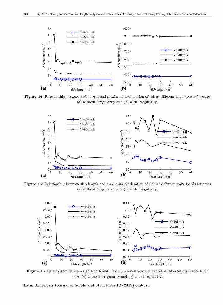
Figure 14: Relationship between slab length and maximum acceleration of rail at different train speeds for cases
(a) without irregularity and (b) with irregularity.
0 10 20 30 40 50 600
1
2
3
4
5
6
7
8
Slab length (m)
Accele
ration
(m
/s2)
(a)
V=40km/h
V=60km/h
V=90km/h
0 10 20 30 40 50 6010
15
20
25
30
35
40
45
Slab length (m)
Accele
ration
(m
/s2)
(b)
V=40km/h
V=60km/h
V=90km/h
Figure 15: Relationship between slab length and maximum acceleration of slab at different train speeds for cases
(a) without irregularity and (b) with irregularity.
0 10 20 30 40 50 600
0.005
0.01
0.015
0.02
0.025
0.03
0.035
0.04
Slab length (m)
Accele
ration
(m
/s2)
(a)
V=40km/h
V=60km/h
V=90km/h
0 10 20 30 40 50 600.03
0.04
0.05
0.06
0.07
0.08
0.09
0.1
0.11
Slab length (m)
Accele
ration
(m
/s2)
(b)
V=40km/h
V=60km/h
V=90km/h
Figure 16: Relationship between slab length and maximum acceleration of tunnel at different train speeds for
cases (a) without irregularity and (b) with irregularity.

Q.-Y. Xu et al. / Influence of slab length on dynamic characteristics of subway train-steel spring floating slab track-tunnel coupled system 665
Latin American Journal of Solids and Structures 12 (2015) 649-674
0 10 20 30 40 50 6071
72
73
74
75
76
77
78
Slab length (m)
Forc
e (kN
)
(a)
V=40km/h
V=60km/h
V=90km/h
0 10 20 30 40 50 60100
110
120
130
140
150
Slab length (m)
Forc
e (kN
)
(b)
V=40km/h
V=60km/h
V=90km/h
Figure 17: Relationship between slab length and maximum vertical wheel-rail force between the front wheel of
first vehicle and the rail at different train speeds for cases (a) without irregularity and (b) with irregularity.
0 10 20 30 40 50 607.5
8
8.5
9
9.5
10
10.5
11
Slab length (m)
Displ
acem
ent (m
m)
(a)
V=40km/h
V=60km/h
V=90km/h
0 10 20 30 40 50 607
8
9
10
11
12
Slab length (m)
Displ
acem
ent (m
m)
(b)
V=40km/h
V=60km/h
V=90km/h
Figure 18: Relationship between slab length and maximum displacement of rail at different train speeds for cases
(a) without irregularity and (b) with irregularity.
0 10 20 30 40 50 6022
24
26
28
30
32
34
36
38
Slab length (m)
Bendin
g m
om
ent (k
N.m
)
(a)
V=40km/h
V=60km/h
V=90km/h
0 10 20 30 40 50 6020
25
30
35
40
45
50
Slab length (m)
Bendin
g m
om
ent (k
N.m
)
(b)
V=40km/h
V=60km/h
V=90km/h
Figure 19: Relationship between slab length and maximum bending moment of rail at different train speeds for
cases (a) without irregularity and (b) with irregularity.

666 Q.-Y. Xu et al. / Influence of slab length on dynamic characteristics of subway train-steel spring floating slab track-tunnel coupled system
Latin American Journal of Solids and Structures 12 (2015) 649-674
0 10 20 30 40 50 6030
32
34
36
38
40
Slab length (m)
Forc
e (kN
)
(a)
V=40km/h
V=60km/h
V=90km/h
0 10 20 30 40 50 6035
40
45
50
55
60
Slab length (m)
Forc
e (kN
)
(b)
V=40km/h
V=60km/h
V=90km/h
Figure 20: Relationship between slab length and maximum pressure force of fastener at different train speeds for
cases (a) without irregularity and (b) with irregularity.
0 10 20 30 40 50 604
5
6
7
8
9
Slab length (m)
Forc
e (kN
)
(a)
V=40km/h
V=60km/h
V=90km/h
0 10 20 30 40 50 604
6
8
10
12
14
16
18
20
Slab length (m)
Forc
e (kN
)
(b)
V=40km/h
V=60km/h
V=90km/h
Figure 21: Relationship between slab length and maximum tensile force of fastener at different train speeds for
cases (a) without irregularity and (b) with irregularity.
0 10 20 30 40 50 6010
20
30
40
50
60
70
80
Slab length (m)
Bendin
g m
om
ent (k
N.m
)
(a)
V=40km/h
V=60km/h
V=90km/h
0 10 20 30 40 50 6030
40
50
60
70
80
90
100
Slab length (m)
Bendin
g m
om
ent (k
N.m
)
(b)
V=40km/h
V=60km/h
V=90km/h
Figure 22: Relationship between slab length and maximum longitudinal bending moment of slab at different
train speeds for cases (a) without irregularity and (b) with irregularity.

Q.-Y. Xu et al. / Influence of slab length on dynamic characteristics of subway train-steel spring floating slab track-tunnel coupled system 667
Latin American Journal of Solids and Structures 12 (2015) 649-674
0 10 20 30 40 50 6046
48
50
52
54
56
58
60
62
Slab length (m)
Forc
e (k
N)
(a)
V=40km/h
V=60km/h
V=90km/h
0 10 20 30 40 50 6045
50
55
60
65
70
Slab length (m)
Forc
e (k
N)
(b)
V=40km/h
V=60km/h
V=90km/h
Figure 23: Relationship between slab length and maximum vertical force of steel spring at different train speeds
for cases (a) without irregularity and (b) with irregularity.
0 5 10 15 20-50
0
50
T ime (s)
Accele
ration (m
/s2)
(a) 101
102
103
0
0.5
1
1.5
2
Frequency (Hz)
Accele
ration (m
/s2)
(b)
Figure 24: Time history (a) and frequency distribution (b) of acceleration of the front wheel of the first vehicle
for Case 39.
0 5 10 15 20-10
-5
0
5
10
T ime (s)
Acc
ele
ration
(m
/s2)
(a) 100
101
102
0
0.1
0.2
0.3
0.4
Frequency (Hz)
Acc
ele
ration
(m
/s2)
(b)
Figure 25: Time history (a) and frequency distribution (b) of acceleration of the front bogie of the first vehicle
for Case 39.
0 5 10 15 20-0.4
-0.2
0
0.2
0.4
T ime (s)
Accele
ration (m
/s2)
(a) 10-1
100
101
0
0.02
0.04
0.06
Frequency (Hz)
Accele
ration (m
/s2)
(b)
Figure 26: Time history (a) and frequency distribution (b) of acceleration of the car body at the middle point of
first vehicle for Case 39.

668 Q.-Y. Xu et al. / Influence of slab length on dynamic characteristics of subway train-steel spring floating slab track-tunnel coupled system
Latin American Journal of Solids and Structures 12 (2015) 649-674
0 5 10 15 20-0.06
-0.04
-0.02
0
0.02
0.04
T ime (s)
Angula
r accele
ration (ra
d/s2
)
(a) 10-1
100
101
0
2
4
6
8x 10
-3
Frequency (Hz)
Angula
r accele
ration (ra
d/s2
)
(b)
Figure 27: Time history (a) and frequency distribution (b) of angular acceleration of the car body of the first
vehicle for Case 39.
0 5 10 15 20-600
-400
-200
0
200
400
600
Time (s)
Accele
ration
(m
/s2)
(a)10
110
210
30
1
2
3
4
5
Frequency (Hz)
Accele
ration
(m
/s2)
(b) Figure 28: Time history (a) and frequency distribution (b) of acceleration of the rail for Case 39.
0 5 10 15 20-30
-20
-10
0
10
20
30
T ime (s)
Accele
ration
(m/s2)
(a)10
110
210
30
0.2
0.4
0.6
0.8
1
1.2
1.4
Frequency (Hz)
Accele
ration
(m/s2)
(b) Figure 29: Time history (a) and frequency distribution (b) of acceleration of the slab for Case 39.
0 5 10 15 20-0.06
-0.04
-0.02
0
0.02
0.04
0.06
0.08
T ime (s)
Accele
ration (m
/s2)
(a)10
010
110
20
1
2
3
4
5
6x 10
-3
Frequency (Hz)
Accele
ration (m
/s2)
(b) Figure 30: Time history (a) and frequency distribution (b) of acceleration of the tunnel for Case 39.

Q.-Y. Xu et al. / Influence of slab length on dynamic characteristics of subway train-steel spring floating slab track-tunnel coupled system 669
Latin American Journal of Solids and Structures 12 (2015) 649-674
From Figure 10-30, the following points can be observed:
(1) It can be seen from Figure 10a, 11a, 14a, 15a, and 16a that although the accelerations of
wheelset, bogie, rail, slab, and tunnel do not change monotonically with the increase of slab
length under the smooth track condition, the overall rule is quite obvious, that is, the shorter the
slab length is, the larger the acceleration is. Acceleration changes little when the slab length exce-
eds the distance between two bogies of a vehicle (12.6 m in this study).
(2) It can be seen from Figure 12a and Figure 13a that the vertical acceleration and angular
acceleration of car body do not change monotonically with the increase of slab length under the
smooth track condition, and there are many fluctuations when slab length is less than 22.5m.
Although the influence law of slab length on the dynamic responses of car body is very complex,
it still can be seen from Figure 12a and Figure 13a that when the slab length is around 11.25m,
the vertical acceleration and angular acceleration of car body are relatively small and they change
little when the slab length exceeds 22.5m.
(3) As is clear from Figure 10-16, the random track irregularity has substantial influence on
the vibration acceleration of wheelset, bogie, car body, rail, slab, and tunnel. For example, the
maximum vertical acceleration of the rail under the random track irregularity condition is about
several hundred times of that under the perfectly smooth track condition. The maximum vertical
acceleration of the first car body under the random track irregularity condition is about 2.7-8.3
times of that under the perfectly smooth track condition.
(4) From Figure 10-16, it can be seen that the influence of the slab length on the vibration ac-
celeration of wheelset, bogie, car body, rail, slab, and tunnel under the random track irregularity
condition varies. It is closely related to the dominant frequency distribution of the vibration acce-
leration of the components of the coupled system (Figures 24b-30b). Generally speaking, the lo-
wer the dominant frequency distribution of the vibration acceleration of the components of the
coupled system is, the greater the influence of the slab length is. The main reason for this condi-
tion is that the excitation frequency caused by the moving train at a constant speed v passing
slab length L is v/L, whose value is low under the normal operation condition of the subway
train, so the slab length has greater influence on the vibration acceleration of the coupled system
whose dominant frequency is low.
Because the dominant frequency distribution of the acceleration of the bogie, wheel, rail, slab,
and tunnel is relatively higher than the slab passing frequency, the vibration acceleration of the
bogie, wheel, rail, slab, and tunnel are affected far more by the random track irregularity than by
the slab length. The maximum acceleration of the bogie, wheel, rail, slab, and tunnel does not
necessarily appear in the short length FST. However, because the dominant frequency distribu-
tion of the acceleration of the car body is relatively low, the slab length has greater influence on
the vibration acceleration of the car body than that of the bogie, wheel, rail, slab, and tunnel.
The maximum acceleration of the car body tends to become smaller with increasing slab length,
although there are some fluctuations because of the influence of random track irregularity.
(5) From Figure 14b, it is clear that the wheel-rail force variation is very small and it is negli-
gible under the perfectly smooth track condition for train speed under 60km/h. And it is also
negligible under the perfectly smooth track condition for train speed at 90km/h when slab length
is longer than 5m. However, the influence of slab length on the wheel-rail interaction force under
the random track irregularity condition is complex. The maximum wheel-rail interaction force

670 Q.-Y. Xu et al. / Influence of slab length on dynamic characteristics of subway train-steel spring floating slab track-tunnel coupled system
Latin American Journal of Solids and Structures 12 (2015) 649-674
does not necessarily appear in the short length FST because of the large influence of random
track irregularity.
(6) It is apparent from Figure 18 that slab length has obvious influence on the maximum ver-
tical displacement of the rail. The maximum vertical displacement of the rail decreases by about
20% with increasing slab length for train speed under 60km/h, and decreases by about 30% for
train speed at 90km/h.
The reason for the reduction is that the force of the steel spring under the slab is relatively
uniform and the displacement of the steel spring under the slab is relatively small when the slab
length is long.
The reason for higher reduction rate of the maximum vertical displacement of the rail for hig-
her subway train speed is that the influence of slab length on dynamic force of fastener and steel
spring which are the main causes of deformation of the track, is much larger when train speed is
higher, as shown in Figures 20-21 and Figure 23.
(7) It is evident from Figure 19 that slab length has significant influence on the bending mo-
ment of the rail. The maximum moment of the rail decreases by about 30% with increasing slab
length for lower train speed under 60km/h, and decreases by about 35-40% for train speed at
90km/h.
The reason for the reduction is that the local deformation of the rail near the ends of two ad-
jacent slabs is relatively small when the slab length is long. Thus, the bending moment of the rail
is relatively small with increasing slab length.
The larger reduction rate of the bending moment of the rail for higher subway train speed is
due to the larger influence of slab length on dynamic wheel-rail force as shown in Figure 17 and
dynamic force of fastener as shown in Figure 20-21, which are closely related to the bending mo-
ment of rail.
(8) It is clear from Figure 20-21 that slab length has some influence on the fastener force. The
maximum pressure force of the fastener decreases by about 7-19% and the maximum tensile force
of the fastener decreases by about 17-71% with increasing slab length for different irregularity
track conditions and train speeds. The reduction rate is closely related to the subway train speed.
The higher subway train speed is , the larger reduction rate will be.
The reason for the reduction is similar to that of the bending moment of rail. The local defor-
mation of the slab is relatively small when the slab length is long.
The reduction rate of the maximum tensile force of the fastener is much larger than that of
the maximum pressure force. The reason is that the pressure force of the fastener is influenced
mainly by the gravity load of the vehicle and random track irregularity rather than by slab
length, while the tensile force of the fastener is closely related to the local deformation of the
track near the ends of two adjacent slabs, which bears a close relationship with slab length.
The reason for larger reduction rate of preesure and tensile fastener force for higher subway
train speed is due to the larger influence of slab length on dynamic response of rail and slab
which are closely related to the fastener preesure and tensile force.
(9) From Figure 22, we can conclude that slab length has substantial influence on the longitu-
dinal bending moment of the slab. The maximum longitudinal bending moment of the slab in-
creases substantially and it is almost doubled with an increase of slab length at first. Then it be-

Q.-Y. Xu et al. / Influence of slab length on dynamic characteristics of subway train-steel spring floating slab track-tunnel coupled system 671
Latin American Journal of Solids and Structures 12 (2015) 649-674
gins to drop slightly. And the maximum longitudinal bending moment of the slab changes little
when the slab length exceeds the distance between two bogies of a vehicle.
The main reason is that when the slab length is short, the bending stiffness of the slab is very
high and the slab acts as a rigid body under the train load, resulting in a small longitudinal ben-
ding moment of the slab. With an increase of slab length, the bending stiffness of the slab reduces
and the slab acts as a flexible beam under the train load. Therefore, the maximum longitudinal
bending moment of the slab increases substantially with increasing slab length at first.
Besides the bending stiffness of the slab, the longitudinal bending moment is also related to
the force of the steel spring which decreases with increasing slab length; therefore, the longitudi-
nal bending moment drops slightly when the slab length exceeds some value. The force of the
steel spring is nearly constant when the slab length exceeds the distance between two bogies of a
vehicle, so the longitudinal bending moment of the slab changes little when the slab length exce-
eds the distance between the two bogies of a vehicle.
(10) As is apparent from Figure 23, the slab length has large influence on the maximum verti-
cal force of the steel spring. The maximum vertical force of the steel spring decreases by about
12-25% with an increase of slab length for different irregularity track conditions and train speeds.
The force of the steel spring is nearly constant when the slab length exceeds the distance between
two bogies of a vehicle.
The reason for the reduction is that the local deformation of the slab near the ends of two ad-
jacent slabs is relatively large when the slab length is short, so the steel spring near the ends of
two adjacent slabs of shorter length bears more pressure forces.
The reason for larger reduction rate of steel spring force for higher subway train speed is due
to the larger influence of slab length on dynamic response of the slab and the force acting on the
slab, which are closely related to the steel spring force.
7 CONCLUSIONS AND RECOMMENDATIONS
A subway train-SSFST-tunnel coupling dynamic model considering short and middle to long wa-
velength random track irregularities, as well as longitudinal connection between adjacent slabs of
SSFST, is developed. Based on this model, the influence of slab length on dynamic characteristics
of the system under different track irregularity conditions and train speeds is theoretically stu-
died. The following conclusions can be obtained:
(1) In general, under the perfectly smooth track condition, the dynamic performance of the
bogie, wheel, rail, slab, and tunnel is improved with increasing slab length, although vibration
accelerations of these components do not decrease monotonically with increasing slab length. The
influence of slab length on dynamic performance of the car body is more complex than other
components of the coupled system. There are still some influence laws that the vertical accelera-
tion and angular acceleration of car body are relatively small when the slab length is around
11.25m and they change little when the slab length exceeds 22.5m.
(2) Slab length has varying influence on the vibration acceleration of the subway train-SSFST-
tunnel coupled system under the random track irregularity condition. Generally speaking, the
lower the dominant frequency distribution of the vibration acceleration is, the greater the influen-
ce of slab length is. The maximum bogie acceleration, wheel acceleration, rail acceleration, slab

672 Q.-Y. Xu et al. / Influence of slab length on dynamic characteristics of subway train-steel spring floating slab track-tunnel coupled system
Latin American Journal of Solids and Structures 12 (2015) 649-674
acceleration, and tunnel acceleration do not necessarily appear in the short length FST because of
the significant influence of random track irregularity. The maximum acceleration of the car body
tends to become smaller with increasing slab length, although there are small fluctuations because
of the influence of track irregularity.
(3) Slab length has significant impact on the force of rail, fastener, and steel spring regardless
of the track irregularity condition. With an increase of slab length, the force of rail, fastener, and
steel spring also decreases significantly, which helps to lengthen the service life of these compo-
nents. Slab length has significant influence on the dynamic force of rail, fastener, and steel spring
when train speed is higher.
(4) Slab length has significant influence on the longitudinal bending moment of the slab re-
gardless of track irregularity condition. The maximum longitudinal bending moment of the slab
increases substantially and is almost doubled with an increase of slab length at first, then it be-
gins to drop slightly, and the maximum longitudinal bending moment of the slab changes little
when the slab length exceeds the distance between two bogies of a vehicle. Some effective measu-
res, such as increasing the height of the slab and using more steel bars in the slab, should be ta-
ken to improve the bending resistance capacity of long length slabs. Slab length has significant
influence on the longitudinal bending moment of the slab when train speed is higher.
(5) Slab length around 11.25m or above 22.5m is recommended for underground SSFST when
the operation speed of subway train is moderate. Slab length above 22.5m is recommended when
the operation speed of subway train is very high.
Acknowledgments
The study is supported by the Natural Science Foundation of China (Nos. 51178469 and
51078360), the National Science Joint High Speed Railway Foundation of China (No. U1334203),
and the State Scholarship Fund of China Scholarship Council (No. 201208430112).
References
Andersson, E., Berg, M., Stichel, S., (1998). Rail Vehicle Dynamics: Fundamentals and Guidelines. Royal Institu-
te of Technology (KTH), Stockholm.
Au, F.T.K., Wang, J.J., Cheung, Y.K., (2002). Impact study of cable-stayed railway bridges with random rail
irregularities. Engineering Structures 24(5): 529-541.
Auersch, L., (2012). Dynamic Behavior of Slab Tracks on Homogeneous and Layered Soils and the Reduction of
Ground Vibration by Floating Slab Tracks. Journal of Engineering Mechanics 138(8): 923-933.
Bowe, C.J., Mullarkey, T.P., (2005). Wheel-rail contact elements incorporating irregularities. Advances in Engi-
neering Software 36(11): 827-837.
Chen, G., Zhai, W.M., (1999). Numerical simulation of the stochastic process of railway track irregularities. Jour-
nal of Southwest Jiaotong University 34(2): 132-137 (in Chinese).
Cox, S.J., Wang, A., Morison, C., Carels, P., Kelly, R., Bewes, O.G., (2006). A test rig to investigate slab track
structures for controlling ground vibration. Journal of Sound and Vibration 293(3): 901-909.
Ding, D.Y., Liu, W.N., Li, K.F., Sun, X.J., Liu, W.F., (2011). Low frequency vibration tests on a floating slab
track in an underground laboratory. Journal of Zhejiang University SCIENCE A 12(5): 345-359 (in Chinese).

Q.-Y. Xu et al. / Influence of slab length on dynamic characteristics of subway train-steel spring floating slab track-tunnel coupled system 673
Latin American Journal of Solids and Structures 12 (2015) 649-674
Dings, P.C., Dittrich, M.G., (1996). Roughness on Dutch railway wheels and rails. Journal of Sound and Vibrati-
on 193(1): 103-112.
Forrest, J.A., Hunt, H.E.M., (2006). Ground vibration generated by trains in underground tunnels. Journal of
Sound and Vibration 294(4): 706-736.
Gardien, W., Stuit, H.G., (2003). Modelling of soil vibrations from railway tunnels. Journal of Sound and Vibrati-
on 267(3): 605-619.
Gupta, S., Degrande, G., (2010). Modelling of continuous and discontinuous floating slab tracks in a tunnel using
a periodic approach. Journal of Sound and Vibration 329(8): 1101-1125.
Gupta, S., Hussein, M.F.M., Degrande, G., Hunt, H.E.M., Clouteau, D., (2007). A comparison of two numerical
models for the prediction of vibrations from underground railway traffic. Soil Dynamics and Earthquake Enginee-
ring 27(7): 608-624.
Gupta, S., Liu, W.F., Degrande, G., Lombaert, G., Liu, W.N., (2008). Prediction of vibrations induced by under-
ground railway traffic in Beijing. Journal of Sound and Vibration 310(3): 608-630.
Hamid, A., Yang, T.L., (1981). Analytical descriptions of track-geometry variations. Transportation Research
Record 838: 19-26.
Hung, H.H., Chen, G.H., Yang, Y.B., (2013). Effect of railway roughness on soil vibrations due to moving trains
by 2.5 D finite/infinite element approach. Engineering Structures 57: 254-266.
Hussein, M.F.M., Hunt, H.E.M., (2006). Modelling of floating-slab tracks with continuous slabs under oscillating
moving loads. Journal of Sound and Vibration 297(1): 37-54.
Hussein, M.F.M., Hunt, H.E.M., (2009). A numerical model for calculating vibration due to a harmonic moving
load on a floating-slab track with discontinuous slabs in an underground railway tunnel. Journal of Sound and
Vibration 321(1): 363-374.
Iyengar, R.N., Jaiswal, O.R., (1995). Random field modeling of railway track irregularities. Journal of Transporta-
tion Engineering 121(4): 303-308.
Ju, S.H., Liao, J.R., Ye, Y.L., (2010). Behavior of ground vibrations induced by trains moving on embankments
with rail roughness. Soil Dynamics and Earthquake Engineering 30(11): 1237-1249.
Kitagawa, T., Thompson, D.J., (2006). Comparison of wheel/rail noise radiation on Japanese railways using the
TWINS model and microphone array measurements. Journal of Sound and Vibration 293(3): 496-509.
Kuo, C.M., Huang, C.H., Chen, Y.Y., (2008). Vibration characteristics of floating slab track. Journal of Sound
and Vibration 317(3): 1017-1034.
Lei, X., Noda, N.A., (2002). Analyses of dynamic response of vehicle and track coupling system with random
irregularity of track vertical profile. Journal of Sound and Vibration 258(1): 147-165.
Li, K.F., Liu, W.N., Sun, X.J., Ding, D.Y., Yuan, Y., (2011). In-situ Test of Vibration Attenuation of Under-
ground Line of Beijing Metro Line 5. Journal of the China Railway Society 33(4): 112-118 (in Chinese).
Lombaert, G., Degrande, G., Vanhauwere, B., Vandeborght, B., François, S., (2006). The control of ground-borne
vibrations from railway traffic by means of continuous floating slabs. Journal of Sound and Vibration 297(3): 946-
961.
Lou, P., (2007). Finite element analysis for train–track–bridge interaction system. Archive of Applied Mechanics
77(10): 707-728.
Lou, P., Zeng, Q.Y., (2005). Formulation of equations of motion of finite element form for vehicle-track-bridge
interaction system with two types of vehicle model. International Journal for Numerical Methods in Engineering
62(3): 435-474.
Müller, K., Grundmann, H., Lenz, S., (2008). Nonlinear interaction between a moving vehicle and a plate elas-
tically mounted on a tunnel. Journal of Sound and Vibration 310(3): 558-586.
674 Q.-Y. Xu et al. / Influence of slab length on dynamic characteristics of subway train-steel spring floating slab track-tunnel coupled system
Latin American Journal of Solids and Structures 12 (2015) 649-674
Sato, Y., (1977). Study on high-frequency vibrations in track operated with high-speed trains. Quarterly Reports
of Railway Technical Research Institute 18(3): 109-114.
Saurenman, H., Phillips, J., (2006). In-service tests of the effectiveness of vibration control measures on the
BART rail transit system. Journal of Sound and Vibration 293(3): 888-900.
Vogiatzis, K., (2012). Environmental ground borne noise and vibration protection of sensitive cultural receptors
along the Athens Metro Extension to Piraeus. Science of the Total Environment 439: 230-237.
Wu, T.X., Thompson, D.J., (2000). Theoretical investigation of wheel/rail non-linear interaction due to roughness
excitation. Vehicle System Dynamics 34(4): 261-282.
Xu, Z.S., (2004). Prediction and control of wheel/ rail noise for rail transit, Ph.D. Thesis (in Chinese), Southwest
Jiaotong University, China.
Zeng, Q.Y., (2000). The principle of total potential energy with stationary value in elastic system dynamics. Jour-
nal of Huazhong University of Science and Technology 28(1): 1-3 (in Chinese).
Zhai, W., Cai, Z., (1997). Dynamic interaction between a lumped mass vehicle and a discretely supported contin-
uous rail track. Computers & structures 63(5): 987-997.
Zhang, N., Xia, H., (2013). Dynamic analysis of coupled vehicle–bridge system based on inter-system iteration
method. Computers & Structures 114: 26-34.