Embed Size (px)
Citation preview
Int J Fatigue 13 No 5 (1991) pp 405-409
Influence of misalignment on the fatigue strength of butt welds
J .M. Ferreira and C.M. Branco
A study is presented concerning the influence of misalignment on the fatigue behaviour of transversely loaded butt welded joints. The following main types of misalignment were analysed: parallel misalignment between two plates with equal or different thickness, longitudinal seams in tubular connections and also angular misalignment. An LEFM approach was used to predict crack propagation life. The theoretical predictions for the joints between plates with equal thickness and with parallel and angular misalignment were compared against experimental results taken from the literature, and good agreement was found. In the case of parallel misalignment and equal plate thicknesses a crack initiation model was applied and the total S - N curves were obtained for the fatigue life of the joint.
Key words: fatigue strength; misalignment; butt welds
Many design codes specify the level of permissible misalign- ment in butt welds. However, the majority of misalignment requirements come from 'good practical experience' and not as a result of a strength analysis where a fitness for purpose analysis is carried out. It is very important to assess the influence, of misalignment in the fatigue strength of the joint. Misalignment leads to an increase of local stress due to the presence of the resulting secondary bending stresses.
In this work parallel misalignment is analysed in joints with equal (Fig. l(a)) or different thicknesses (Fig. l(b)) and also in longitudinal weld seams in tubes (Fig. l(c)). Results for angular misalignments, as sketched in Fig. l(d), are also presented.
The fatigue analysis was made with an LEFM approach and a Paris-type law. The integration of the Paris law was carried out assuming semicircular flaws with 0.15 mm initial depth located at the weld toe and propagating in the thickness direction. The Raju and Newman equation ~ for semi-elliptical cracks in plates was chosen as the base stress intensity equation.
The values of C and rn taken in the Paris law were m = 3.0 (for crack length and crack depth directions); CA (in the depth direction) = 1.83 × 10 -13 and CB (in the surface or crack length direction) = 1.334 × 10 ~3 (all units in mm cycle -~ and N mm 3/2). The final crack length was assumed to be one half of the plate thickness.
The appropriate stress intensity equation was obtained by forming the product of the Raju and Newman base equation with the Mk magnifying factor. 2 Mk was obtained for each geometry and crack length using the superposition principle.
Hence for all cases except the misalignment in tubes Mk was computed as a relation between the stress intensity factor in the weldment obtained by an FE program using eight-node isoparametric crack tip elements 3 and the K equation for a similar geometry and loading without the weldment (in this case the Srawley equation; 4 plate in tension with a full-depth corner crack).
For misalignment in tubes a similar approach was applied
0142-1123/91/050405-05 © 1 Int J Fatigue September 1991
but the weight function method was used instead of the calculation of K. Here the base solution for K was also given by weight functions (Glinka weight function s) for the same relations of thickness over inner tube radius.
The fatigue life predictions are compared against available experimental results.
Results and discussion
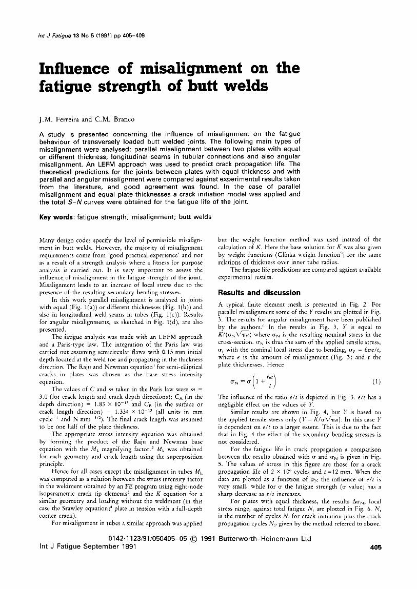
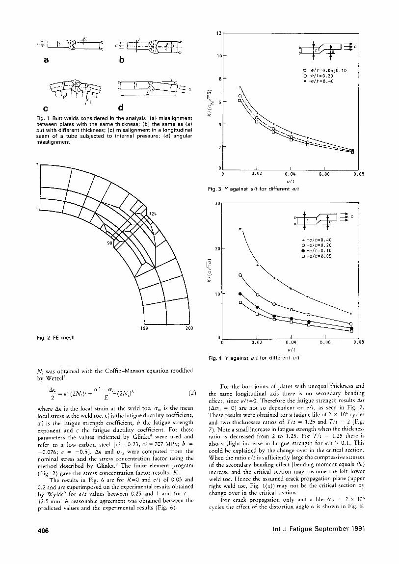
A typical finite element mesh is presented in Fig. 2. For parallel misalignment some of the Y results are plotted in Fig. 3. The results for angular misalignment have been published by the authors. 6 In the results in Fig. 3, Y is equal to K/ (o N ' ~a ) where crN is the resulting nominal stress in the cross-section. ON is thus the sum of the applied tensile stress, ~r, with the nominal local stress due to bending, ~rp = 6~e/t, where e is the amount of misalignment (Fig. 3) and t the plate thicknesses. Hence
o-N = o- (1 + 6:) (1)
The influence of the ratio e/t is depicted in Fig. 3. e/t has a negligible effect on the values of Y.
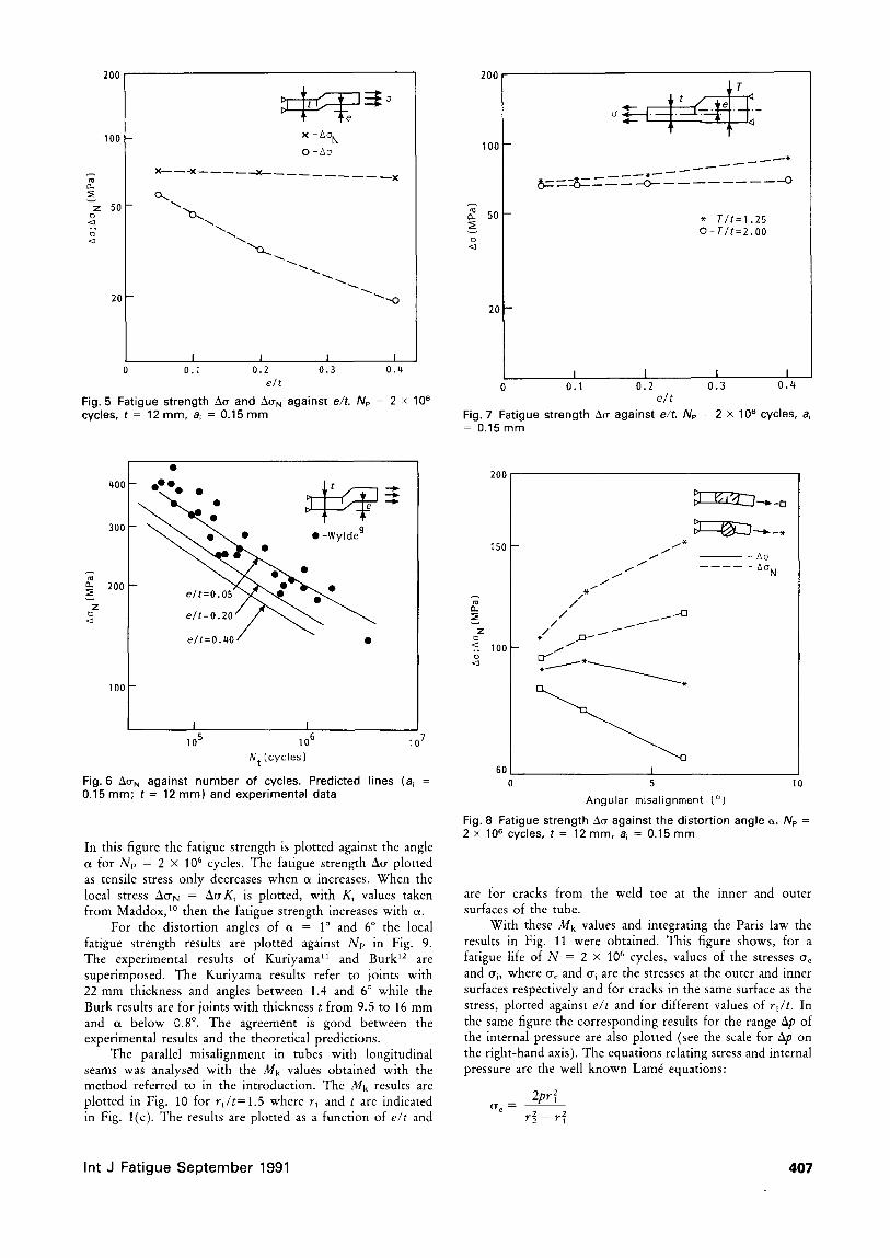
Similar results are shown in Fig. 4, but Y is based on the applied tensile stress only (Y = K/~-a~a). In this case Y is dependent on e/t to a larger extent. This is due to the fact that in Fig. 4 the effect of the secondary bending stresses is not considered.
For the fatigue life in crack propagation a comparison between the results obtained with ~ and ~N is given in Fig. 5. The values of stress in this figure are those for a crack propagation life of 2 × 10 6 cycles and t =12 mm. When the data are plotted as a function of ~rN the influence of e/t is very small, while for ~ the fatigue strength (~r value) has a sharp decrease as e/t increases.
For plates with equal thickness, the results AcrN, local stress range, against total fatigue Nt are plotted in Fig. 6. Nt is the number of cycles Ni for crack initiation plus the crack propagation cycles Np given by the method referred to above.
991 Butterworth-Heinemann Ltd 405
l
a b
H L .~o ,I
c d Fig. 1 Butt welds considered in the analysis: (a) misal ignment between plates with the same thickness; (b) the same as (a) but with different thickness; (c) misalignment in a longitudinal seam of a tube subjected to internal pressure; (d) angular misalignment
Fig. 2 FE m e s h
199 203
Ni was obtained with the Coffin-Manson equation modified by WetzeF
t - - O "
~i~ ' ( 2 N J + ~! m(2N~)b (2) 2 = ~ f
where Al~ is the local strain at the weld toe, Crm is the mean local stress at the weld toe, ~ is the fatigue ductility coefficient, ~; is the fatigue strength coefficient, b the fatigue strength exponent and c the fatigue ductility coefficient. For these parameters the values indicated by Glinka" were used and refer to a low-carbon steel (~ = 0.23;~; = 707 MPa; b = -0.076; c = -0 .5) . ~ and ~m were computed from the nominal stress and the stress concentration factor using the method described by Glinka. 8 The finite element program (Fig. 2) gave the stress concentration factor results, K,.
The results in Fig. 6 are for R=0 and e/t of 0.05 and 0.2 and are superimposed on the experimental results obtained by Wylde 9 for e/t values between 0.25 and 1 and for t - 12.5 mm. A reasonable agreement was obtained between the predicted values and the experimental results (Fig. 6).
12
10
z 6 t~
4--
2--
0 I 1 I 0 0.02 0.04 0.06
a/t
Fig. 3 Y against a/ t for different e/t
[] -e/t=O.05;0.10 0 -e/t=0.20 * -e/t=0.40
\ \
D
0.08
30
20
~ k ~ -e/t=O.40 0 -e/t=0.20 II -e/ t=0.10 [] -e/t=O.05
o 1 I I 0 0.02 0.04 0.06 0.08
a/t
Fig. 4 Y against a/t for different e/t
For the butt joints of plates with unequal thickness and the same longitudinal axis there is no secondary bending effect, since e/t=O. Therefore the fatigue strength results Ai~ (~rb = 0) are not so dependent on e/t, as seen in Fig. 7. These results were obtained for a fatigue life of 2 × 10⁶ cycles and two thicknesses ratios of T/t = 1.25 and T/t = 2 (Fig. 7). Note a small increase in fatigue strength when the thickness ratio is decreased from 2 to 1.25. For T/t = 1.25 there is also a slight increase in fatigue strength for e/t > 0.1. This could be explained by the change over in the critical section. When the ratio e/t is sufficiently large the compressive stresses of the secondary bending effect (bending moment equals Pe) increase and the critical section may become the left lower weld toe. Hence the assumed crack propagation plane (upper right weld toe, Fig. l(a)) may not be the critical section by change over in the critical section.
For crack propagation only and a life N~ = 2 × 10 ~' cycles the effect of the distortion angle c~ is shown in Fig. 8.
406 Int J Fa t i gue S e p t e m b e r 1991
200 200
100 -
z 5 0 - t~ .<3
t~ <3
20
x - A o N 0 - A o
X X . - ~ - X
o..
I I 1 I 0.1 0.2 0.3 0.4
elt
Fig. 5 Fatigue strength A~ and AO" N against e/t. Np = 2 × 10⁸ cycles, t = 12 m m , a~ = 0.15 m m
100
~" 5O
tD <3
20
O
t~- ----8- - o- R ~ . - - O
* - T I t = l .25 O-Ti t=2.00
I I I I 0.1 0.2 0.3 0.4
elt
Fig. 7 Fatigue strength ~cr against elt. Np - 2 x 10 ~ cycles, a~ = 0.15 m m
.oo . - . . •
300
200 -
Z t~
i 0 0 1
I I 105 106 107
N t [cycles)
Fig. 6 ~ N a g a i n s t n u m b e r o f c y c l e s . P r e d i c t e d l ines (ai = 0.15 m m ; t = 12 m m ) and exper imenta l data
In this figure the fatigue strength is plotted against the angle (x for N~ = 2 × 10⁶ cycles. The fatigue strength ~l~ plotted as tensile stress only decreases when ct increases. When the local stress ~l~rN = ~l~rKt is plotted, with K, values taken from Maddox, 1° then the fatigue strength increases with c~.
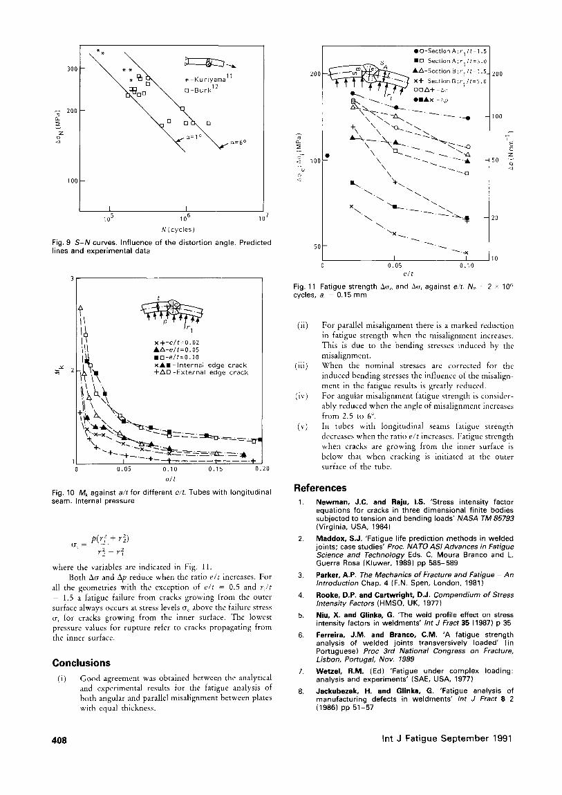
For the distortion angles of c~ = 1 ° and 6 ° the local fatigue strength results are plotted against N~ in Fig. 9. The experimental results of Kuriyama ~l and Burk ~2 are superimposed. The Kuriyama results refer to joints with 22 mm thickness and angles between 1.4 and 6 ° while the Burk results are for joints with thickness t from 9.5 to 16 mm and el below 0.8 °. The agreement is good between the experimental results and the theoretical predictions.
The parallel misalignment in tubes with longitudinal seams was analysed with the Mk values obtained with the method referred to in the introduction. The Mk results are plotted in Fig. 10 for r ~ / t = l . 5 where ri and t are indicated in Fig. l(c). The results are plotted as a function of e / t and
200
m - A O "
A a N
150 -- . / - / * / "
I "
/ , /
/ t -.---O
Z ~ AD......~ o .~. 100 - / J
60 I 0 5 I0
A n g u l a r m i s a l i g n m e n t (o)
Fig. 8 Fa t ig ue s t r e n g t h A~ a g a i n s t t h e d i s t o r t i o n a n g l e a. Np = 2 x 10⁸ cy c l e s , t = 12 ram, oi = 0 .15 m m
are for cracks from the weld toe at the inner and outer surfaces of the tube.
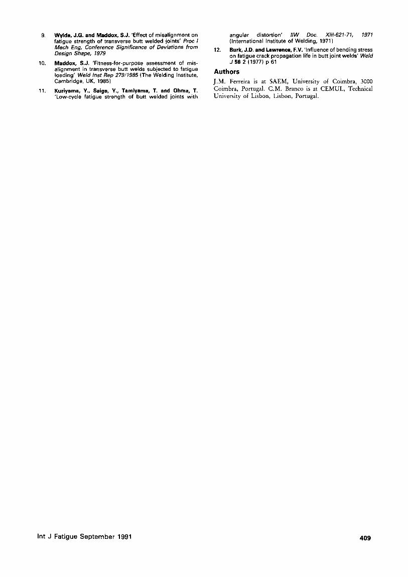
With these Mk values and integrating the Paris law the results in Fig. 11 were obtained. This figure shows, for a fatigue life of N = 2 × 10⁶ cycles, values of the stresses ~ and crl, where ~e and m are the stresses at the outer and inner surfaces respectively and for cracks in the same surface as the stress, plotted against e / t and for different values of r~/t. In the same figure the corresponding results for the range ~lp of the internal pressure are also plotted (see the scale for ~lp on the right-hand axis). The equations relating stress and internal pressure are the well known Lam~ equations:
2pr2~ (]re ~ -
r~ - r~
Int J Fat igue S e p t e m b e r 1991 4 0 7
300
200 g_
Z
I00
. u H ~ . - i , , u r l yama
°\o \ Ja=1° \ - o
I I 105 106 10
N (cycles)
Fig. 9 S-N curves. Influence of the distortion angle. Predicted lines and experimental data
t
x +-e / t=O.02 AZ~-e / t=O. 05 I n - e / t = 0 . 1 0 X A I - I n t e r n a l edge c rack + A D - E x t e r n a l edge crack
~, " l . l x " ~ L , .
0.05 0.10 0.15 0.20 a/t
Fig. 10 Mk against a/tfor different e/t. Tubes with longitudinal seam. Internal pressure
p(r~ + r~,) ( T i = r~, _ ~,
where the variables are indicated in Fig. 11. Both ~cv and Ap reduce when the ratio e/t increases. For
all the geometries with the exception of e/t = 0.5 and ri/t - 1.5 a fatigue failure from cracks growing from the outer surface always occurs at stress levels ~r~ above the failure stress (rl for cracks growing from the inner surface. The lowest pressure values for rupture refer to cracks propagating from the inner surface.
C o n c l u s i o n s
(i) Good agreement was obtained between the analytical and experimental results for the fatigue analysis of both angular and parallel misalignment between plates with equal thickness.
QO-Section A;r I/t=I .5 I S B H-Section A;r I/t:5.0
200 ~ - - ~ ~ " /k -Sect ion B ; r l / t = l .5_ I WI~ ~ ~ ' S x+-Sect i °nB;r l / t=5"O
• ~ 7 O I A x -Ap
{ I. +' ""
100 t - \ "--.- .~. " i -
\ ~'-[] 3 ~ "+x
~ . . ~ .
"~X . . .~.
50- - "~'~" "~" "~X
I I 0.05 0.10
e/t
Fig. 11 Fatigue strength ~(r~ and A(r~ against e/t. Np cycles, a~ = 0.15 mm
200
100
E E
z 50
o_
20
10
= 2 x l O 6
(ii) For parallel misalignment there is a marked reduction in fatigue strength when the misalignment increases. This is due to the bending stresses induced by the misatignment.
(iii) When the nominal stresses arc corrected for the induced bending stresses the influence of the misalign- ment in the fatigue results is greatly reduced.
(iv) For angular misalignment fatigue strength is consider- ably reduced when the angle of misalignment increases from 2.5 to 6 ° .
(v) In tubes with longitudinal seams fatigue strength decreases when the ratio e/t increases. Fatigue strength when cracks are growing from the inner surface is below that when cracking is initiated at the outer surface of the tube.
R e f e r e n c e s
1. Newman, J.C. and Raju, I.S. 'Stress intensity factor equations for cracks in three dimensional finite bodies subjected to tension and bending loads' NASA TM 85793 (Virginia, USA, 1984)
2. Maddox, S.J. 'Fatigue life prediction methods in welded joints; case studies' Prec. NA TO ASI Advances in Fatigue Science and Technology Eds. C. Moura Branco and L. Guerra Rosa {Kluwer, 1989) pp 585-589
3. Parker, A.P. The Mechanics of Fracture and Fatigue - An Introduction Chap. 4 (F.N. Spen, London, 1981)
4. Rooke, D.P. and Cartwright, D.J. Compendium of Stress Intensity Factors (HMSO, UK, 1977)
5. Niu, X. and Glinka, G. 'The weld profile effect on stress intensity factors in weldments' Int J Fract 35 (1987) p 35
6. Ferreira, J.M. and Branco, C.M. 'A fatigue strength analysis of welded joints transversively loaded' (in Portuguese) Proc 3rd National Congress on Fracture, Lisbon, Portugal, Nov. 1989
7. Wetzel, R.M. (Ed) 'Fatigue under complex loading: analysis and experiments' (SAE, USA, 1977)
8. Jackubezak, H. and Glinka, G. 'Fatigue analysis of manufacturing defects in weldments' Int J Fract 8 2 (1986) pp 51-57
408 In t J F a t i g u e S e p t e m b e r 1991
9. Wylde, J.G. and Maddox, S.J. 'Effect of misalignment on fatigue strength of transverse butt welded joints' Proc / Mech Eng, Conference Significance of Deviations from Design Shape, 1979
10. Maddox, S.J. 'Fitness-for-purpose assessment of mis- alignment in transverse butt welds subjected to fatigue loading' Weld Inst Rep 279/1985 (The Welding Institute, Cambridge, UK, 1985)
11. Kuriyama, Y., Saiga, Y., Tamiyama, T. and Ohma, T. 'Low-cycle fatigue strength of butt welded joints with
angular distortion' IIW Doc . X111-621-71, 1971 (International Institute of Welding, 1971 )
12. Burk, J.D. and Lawrence, F.V. 'Influence of bending stress on fat!gue crack propagation life in butt joint welds' Weld J 56 2 (1977) p 61
Authors
J.M. Ferreira is at SAEM, University of Coimbra, 3000 Coimbra, Portugal. C.M. Branco is at CEMUL, Technical University of Lisbon, Lisbon, Portugal.
Int J Fat igue Sep tember 1991 409