Embed Size (px)
Citation preview
Influence of micromechanics in composite panels buckling loads
Martín, Alberto1; Ibiza, Carlos
2; Rodríguez-Tembleque, Luis
3
ABSTRACT
In-plane compression loads may cause buckling of fiber-reinforced composite panels. An accurate knowledge of these critical buckling loads is essential for structural design. In all cases of buckling of panels, critical loads increases with the increase in the thickness of the panel, however, more economical solutions can be obtained by keeping the thickness of the plate as small as possible and increasing the stability by considering micromechanical aspect such as: fiber orientation relative to axial direction, fiber aspect ratio or fiber volume fraction. This paper presents some parametric studies to study the influence of micromechanics in the critical buckling load of fiber-reinforced plates and curved panels.
Keywords: Buckling, Composite panels, Fiber-reinforced composites, Micromechanics, Finite element
analysis.
1. INTRODUCTION
Fiber-reinforced composite panels are widely applied in many structural systems in Aerospace, Automobile, Building and Civil Engineering [1]. In many of these applications, the structural systems are subjected to in-plane compression loads what may cause buckling failure. The study of buckling of laminated composite panels has a relatively short history in comparison with isotropic homogeneous panels. Recently, Rikards et al. [2] and Mallela and Upadhyay [3] have studied buckling in composite panels using a finite element analysis (FEA). However, these works do not pay attention to the influence of the micromechanics in the stability (i.e. critical buckling load and mode shapes) of fiber-reinforced panels under axial compression.
The present work considers different micromechanical aspects such as: fiber orientation relative to axial direction ( ), fiber aspect ratio ( , and being the fiber length and diameter, respectively) and fiber volume fraction ( ), and analyzes their influence in the critical buckling load of fiber-reinforced plates and curved panels. So a linear buckling FEA is carried out considering two micromechanical models for continuous and short fiber reinforced composites. The Hopkins and Chamis model [4,5] is considered for continuous fiber-reinforced composites and the Halpin-Tsai model [6] is considered for short fiber-reinforced materials. The proposed numerical model will be applied to compute the critical buckling load and buckling mode shapes of different composite panels, what will makes it possible to show the significant influence on the stability of the these structural systems.
1 Escuela Técnica Superior de Ingeniería. Universidad de Sevilla (SPAIN). E-mail: [email protected] 2 Escuela Técnica Superior de Ingeniería. Universidad de Sevilla (SPAIN). E-mail: [email protected] 3 Escuela Técnica Superior de Ingeniería. Universidad de Sevilla (SPAIN). E-mail: [email protected]
267

Influence of micromechanics in composite panels buckling loads Third International Conference on Mechanical Models in Structural Engineering University of Seville. 24-26 june 2015.
2. FINITE ELEMENT MODELING
In the present work the eigen-buckling analysis is performed for the fiber-reinforced composite panels by using the finite element software ANSYS 14. Modelling panels needs care in defining the proper element, so in this work the ANSYS shell element SHELL281 has been used for the analysis of fiber-reinforced plates and curved panels.
Fig. 1 (a) shows a fiber-reinforced composite rectangular plate in compression whose dimensions are: a=0.7 m and b=0.35 m, and the thickness t=0.0002m. In this problem a single layer is considered, being the fiber orientation φ, the angle between the fiber direction and the x-axis (i.e. compression direction). The finite element mesh details are presented in Fig. 1 (b). After a mesh sensitivity analysis, the plate is discretized using 20 elements in Y direction and 30 elements in X direction. The boundary conditions for all the edges are simply supported as Fig. 1(b) shows.
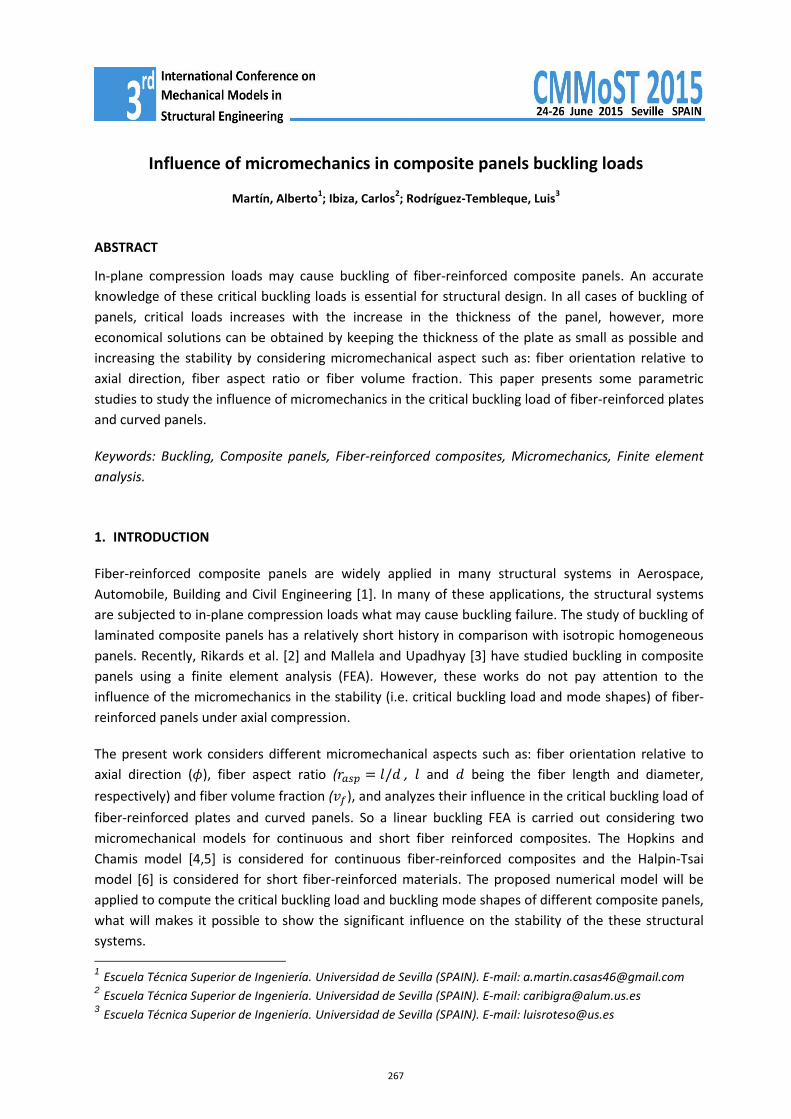
A fiber-reinforced composite curved panel under axial compression is presented in Fig. 2 (a). In this case, a curvature parameter is defined as h/R, so we recover the plate panel when h/R=0 and the cylindrical shell for h/R=1. Fig. 2 (b) presents the finite element details and the boundary conditions. In this case, the eigen-buckling analysis needs a finer mesh compute accurately critical buckling loads and the buckling mode shapes, so the mesh is refined when the curvature parameter increases.
Stability of both panels are analyzed under axial compression. The fiber-reinforced plastic (FRP) is a carbon FRP with a carbon fiber IM7 and 8551-7 epoxy resin as a matrix (IM7 Carbon/ 8551-7). The mechanical properties of fiber and matrix can be found in [7,8] (Table 1). So the composite elastic constants are computed the using the micromechanical equations for continuous FRP (1-9) and short FRP (11-12) presented in Appendix A and B, respectively.
Several examples will be considered using those numerical models varying micromechanical aspects: fiber orientation (φ), fiber volume fraction ( ) or fiber aspect ratio ( ), and the geometrical aspect h/R (i.e. the curvature parameter aspect ratio). The range for the fiber volume ratio will be ={0.45, 0.60, 0.75, 0.8}. In the case of the short fiber micromechanical model, the range of fiber aspect ratio = {10,20,50,100,1000} will be considered. Finally, the influence of the curvature parameter (h/R) on the will be also considered for curved panels. These variations in micromechanical and geometrical parameters will have important consequences in the linear buckling loads (Nx,cr) and mode shapes of these panels. In the following sections, the obtained results for Nx,cr will be presented and commented.
268

Alberto Martín1, Carlos Ibiza
2 and Luis Rodríguez-Tembleque
3
(a)
(b)
Figure 1. (a) Fiber-reinforced composite plate in compression.(b) Finite element mesh details.
Table 1. Mechanical characterization of materials
Fiber properties IM7
276 GPa
19 GPa
19 GPa
27 GPa
0.2
0.2
7 GPa
Matrix Properties 8551-7 Epoxy
4.08 GPa
0.38
1.478 GPa
269
Influence of micromechanics in composite panels buckling loads Third International Conference on Mechanical Models in Structural Engineering University of Seville. 24-26 june 2015.
(a)
(b)
Figure 2. (a) Fiber-reinforced composite curved panel under axial compression. (b) finite element details.
3. BUCKLING OF A FIBER-REINFORCED COMPOSITE PLATE UNDER AXIAL COMPRESSION
3.1. Influence of fiber orientation and fiber volume fraction
In this section the influence of fiber orientation over the critical buckling load and buckling mode shapes is presented for φ = {0o, 15o, 30o, 45o, 60o, 75o, 90o}, under continuous and short fiber micromechanical model assumptions. The range for the fiber volume ratio ={0.45, 0.60, 0.75, 0.8} will be also considered in the numerical test.
270

Alberto Martín1, Carlos Ibiza
2 and Luis Rodríguez-Tembleque
3
Fig. 3 shows the critical load as a function of continuous fiber orientation and different fiber volume fractions. The buckling load Nx,cr is expressed relative to
( ) and presents a maximum for for every fiber volume fraction. Moreover, there is another fact that stands out: buckling loads are higher for than for for every fiber volume ratio considered. This last point shows something interesting because if
the tests were considering traction loads, the tendency would be the opposite, the ultimate load would be higher for than for .
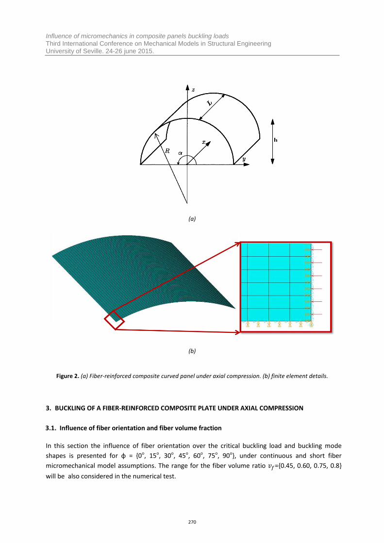
Buckling mode shapes for several orientations and are presented in Fig. 4. In this figure we can see how the number of half-waves in X direction (i.e. load direction) increases with the fiber orientation ( ).
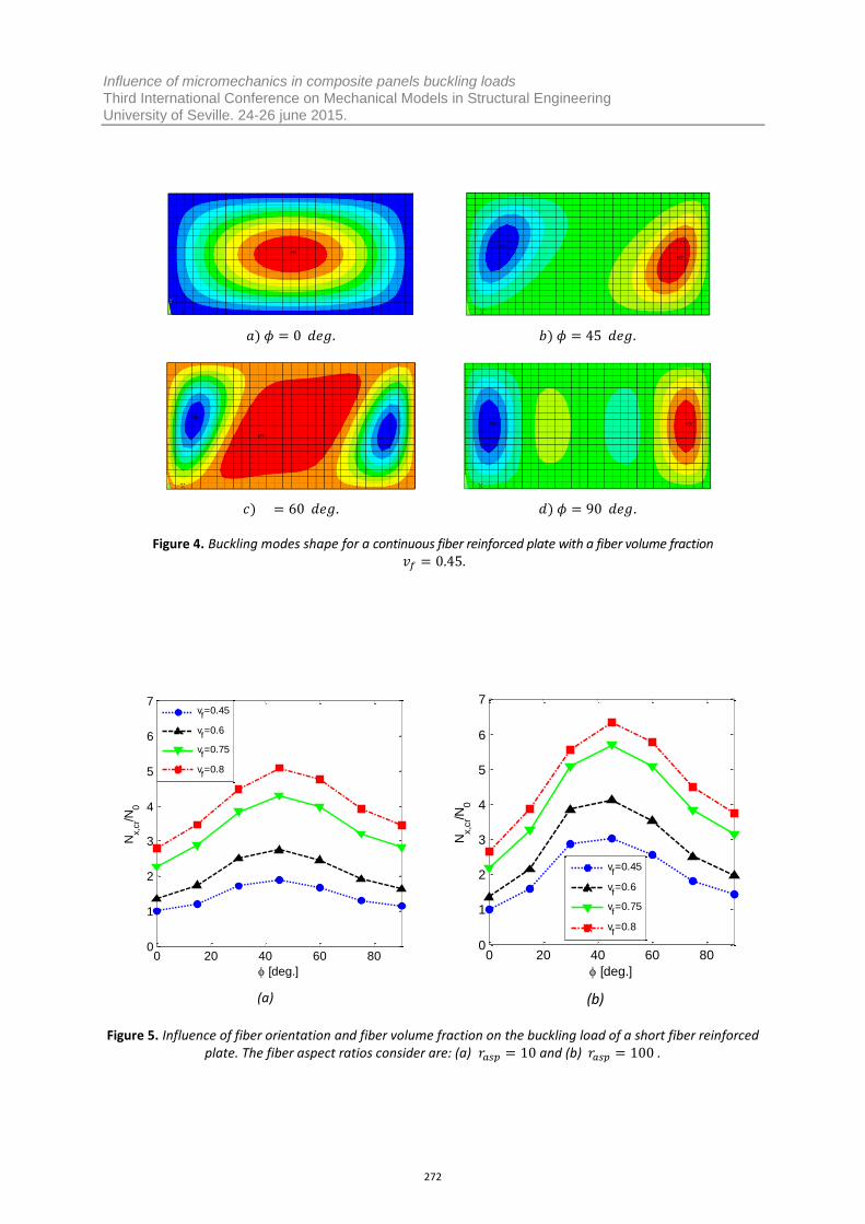
Same results are observed for short fibers reinforced composite (i.e. Halpin-Tsai model) in Fig. 5. In Fig. 5 (a) the fiber aspect ratio is and the relative load is
. In Fig. 5 (b) and . It can be observed in both figures that the tendencies are the same as those seen for continuous fiber. One fact that can be extracted from this figure is that aspect ratio does not change the tendencies of buckling loads with orientation.
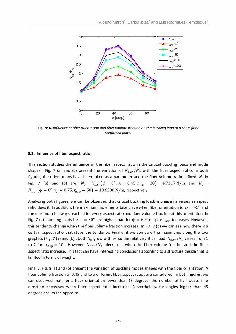
Fig. 6 shows the variation of the relative buckling load with the fiber orientation and the fiber aspect ratio {10, 20, 50, 100, 1000} . The lower values for are obtained for lower values . Furthermore, if we increase , the values for the critical loads converge to the continuous fiber model.
Figure 3. Influence of fiber orientation and fiber volume fraction on the buckling load of a continuous
fiber reinforced plate.
0 20 40 60 800
1
2
3
4
5
6
7
[deg.]
Nx,c
r/N0
vf=0.45
vf=0.6
vf=0.75
vf=0.8
271
Influence of micromechanics in composite panels buckling loads Third International Conference on Mechanical Models in Structural Engineering University of Seville. 24-26 june 2015.
Figure 4. Buckling modes shape for a continuous fiber reinforced plate with a fiber volume fraction .
(a) (b)
Figure 5. Influence of fiber orientation and fiber volume fraction on the buckling load of a short fiber reinforced plate. The fiber aspect ratios consider are: (a) and (b) .
0 20 40 60 800
1
2
3
4
5
6
7
[deg.]
Nx,c
r/N0
vf=0.45
vf=0.6
vf=0.75
vf=0.8
0 20 40 60 800
1
2
3
4
5
6
7
[deg.]
Nx,c
r/N0
vf=0.45
vf=0.6
vf=0.75
vf=0.8
272
Alberto Martín1, Carlos Ibiza
2 and Luis Rodríguez-Tembleque
3
Figure 6. Influence of fiber orientation and fiber volume fraction on the buckling load of a short fiber reinforced plate.
3.2. Influence of fiber aspect ratio
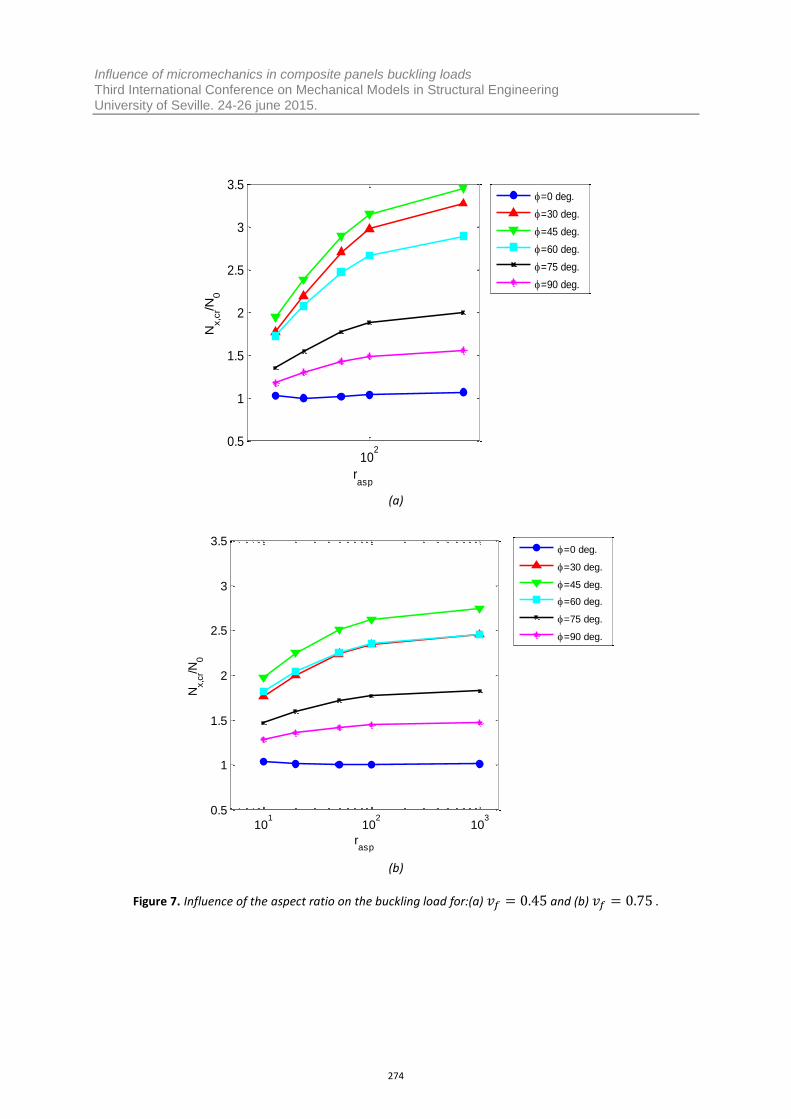
This section studies the influence of the fiber aspect ratio in the critical buckling loads and mode shapes. Fig. 7 (a) and (b) present the variation of with the fiber aspect ratio. In both figures, the orientations have been taken as a parameter and the fiber volume ratio is fixed. in Fig. 7 (a) and (b) are: and
, respectively.
Analyzing both figures, we can be observed that critical buckling loads increase its values as aspect ratio does it. In addition, the maximum increments take place when fiber orientation is and the maximum is always reached for every aspect ratio and fiber volume fraction at this orientation. In Fig. 7 (a), buckling loads for are higher than for despite increases. However, this tendency change when the fiber volume fraction increase. In Fig. 7 (b) we can see how there is a certain aspect ratio that stops the tendency. Finally, if we compare the maximums along the two graphics (Fig. 7 (a) and (b)), both grow with so the relative critical load varies from 1 to 2 for . However, decreases when the fiber volume fraction and the fiber aspect ratio increase. This fact can have interesting conclusions according to a structure design that is limited in terms of weight.
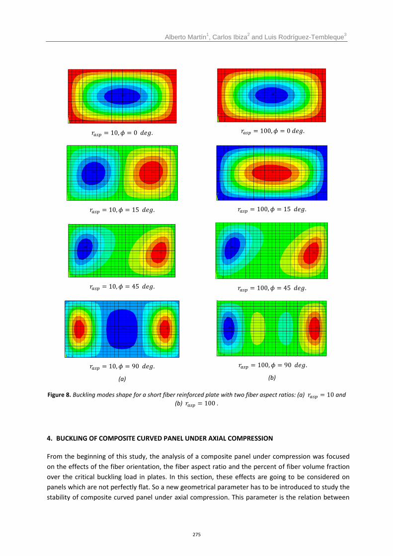
Finally, Fig. 8 (a) and (b) present the variation of buckling modes shapes with the fiber orientation. A fiber volume fraction of 0.45 and two different fiber aspect ratios are considered. In both figures, we can observed that, for a fiber orientation lower than 45 degrees, the number of half waves in x direction decreases when fiber aspect ratio increases. Nevertheless, for angles higher than 45 degrees occurs the opposite.
0 20 40 60 800
0.5
1
1.5
2
2.5
3
3.5
4
[deg.]
Nx,c
r/N0
Cont.
rasp
=10
rasp
=20
rasp
=50
rasp
=100
rasp
=1000
273
Influence of micromechanics in composite panels buckling loads Third International Conference on Mechanical Models in Structural Engineering University of Seville. 24-26 june 2015.
(a)
(b)
Figure 7. Influence of the aspect ratio on the buckling load for:(a) and (b) .
102
0.5
1
1.5
2
2.5
3
3.5
rasp
Nx,c
r/N0
=0 deg.
=30 deg.
=45 deg.
=60 deg.
=75 deg.
=90 deg.
101
102
103
0.5
1
1.5
2
2.5
3
3.5
rasp
Nx,c
r/N0
=0 deg.
=30 deg.
=45 deg.
=60 deg.
=75 deg.
=90 deg.
274
Alberto Martín1, Carlos Ibiza
2 and Luis Rodríguez-Tembleque
3
(a)
(b)
Figure 8. Buckling modes shape for a short fiber reinforced plate with two fiber aspect ratios: (a) and
(b) .
4. BUCKLING OF COMPOSITE CURVED PANEL UNDER AXIAL COMPRESSION
From the beginning of this study, the analysis of a composite panel under compression was focused on the effects of the fiber orientation, the fiber aspect ratio and the percent of fiber volume fraction over the critical buckling load in plates. In this section, these effects are going to be considered on panels which are not perfectly flat. So a new geometrical parameter has to be introduced to study the stability of composite curved panel under axial compression. This parameter is the relation between
275
Influence of micromechanics in composite panels buckling loads Third International Conference on Mechanical Models in Structural Engineering University of Seville. 24-26 june 2015.
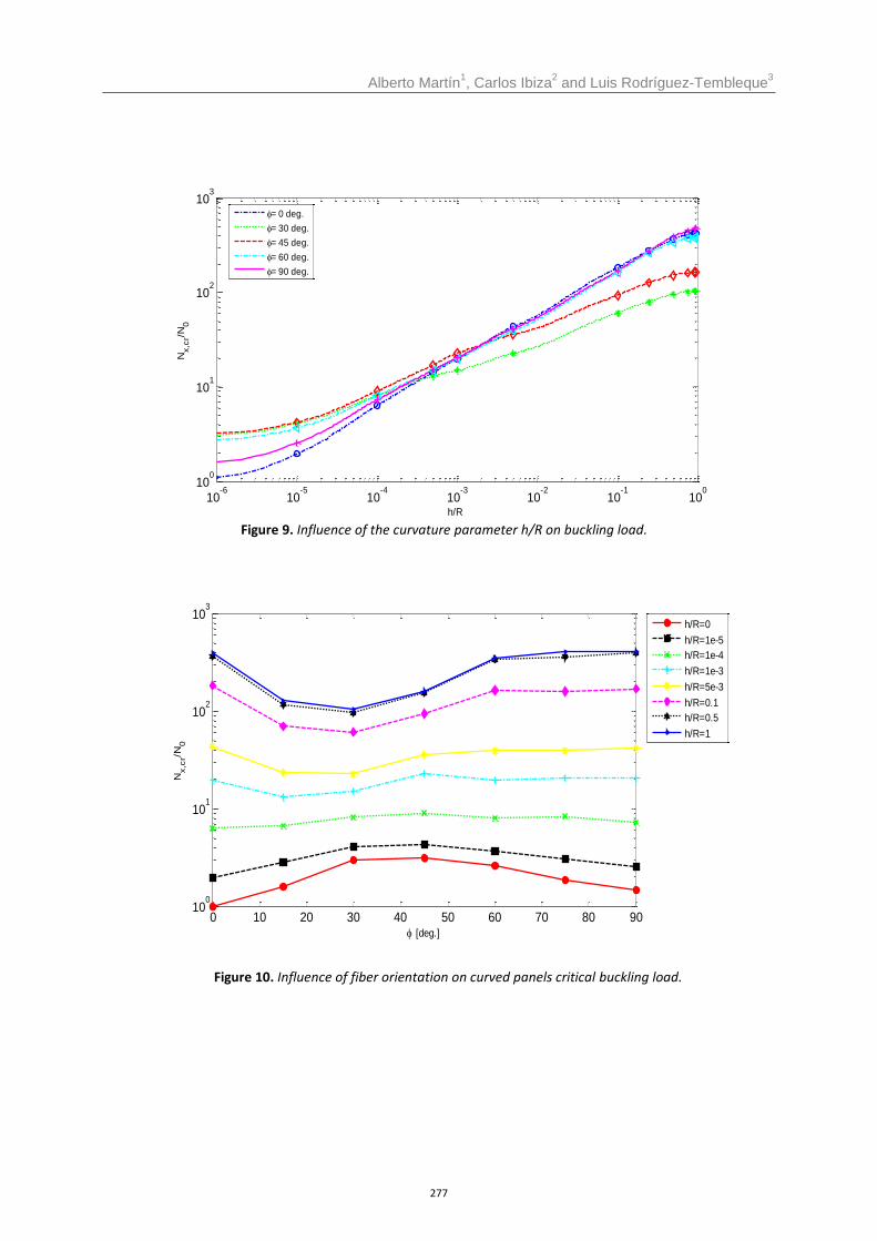
the panel width and its curvature: h/R. (See Fig. 2). In this section, the critical load are presented in Fig. 9 and Fig. 10 relative to , as a function of the curvature parameter h/R and fiber orientation, respectively.
4.1. Influence of curvature parameter h/R variation
Using the same FE model previously mentioned in section 2, the curvature parameter h/R is introduced as a geometry parameter. Considering h/R=0 as a completely flat panel and h/R=1 as a cylindrical curved panel, the relation between the critical buckling load and h/R is shown in Fig. 9.
One of the most significant results is the fact that just increasing h/R a 10%, the critical buckling load is increased 100 or 200 times its value. Moreover, it is important to remark that the increment of the critical buckling load respect to the h/R variation is more pronounced when h/R parameter rounds its minimum values. Different gradients are shown in Fig 9. It is also interesting to stand out the fact that the evolution of the critical buckling load respect of the increment of h/R is different. It depends on the fiber orientations (this fact will be analyzed in the next section).
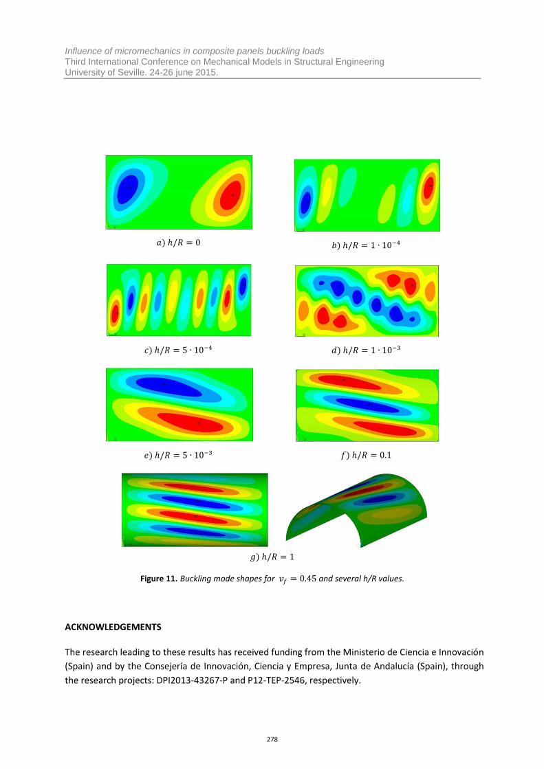
Moreover the buckling shape mode is also affected by the panel curvature. The fact of increasing h/R has the result of increasing the number of half waves in the cylinder axis direction while h/R value is between h/R=0 and h/R=0.1. However, from h/R=0.1 to h/R=1, the half waves are expanded over all the shape, as is shown on the following Fig. 10 in the circumferential axis direction.
4.2. Influence of fiber orientation
The critical buckling load of a composite plate under compression showed a remarkable for having a maximum when the fiber orientation was around the 45 degrees. However, if we observe Fig. 11, when the curvature parameter increases, the maximum value of the critical buckling load as a function of the fiber orientation changes completely. On one hand, values of h/R close to 0 (i.e. flat panels) has the maximum critical buckling load for orientations between 30 and 45 degrees. On the other hand, values of h/R close to 1 (i.e. cylindrical panels) has the maximum critical buckling load for fiber orientation of 0 and 90 degrees.
5. CONCLUSIONS
This work studied the influence of micromechanics (i.e. fiber orientation relative to axial direction, fiber aspect ratio and fiber volume fraction) in the critical buckling load of fiber-reinforced plates and curved panels. A linear buckling FEA considering two micromechanical models for continuous and short fiber reinforced composites has been used to compute the critical buckling load and buckling mode shapes of different composite panels. The results presented show significant influence of micromechanics in the stability of these complex structural systems. So its effect can be essential for structural design.
276
Alberto Martín1, Carlos Ibiza
2 and Luis Rodríguez-Tembleque
3
Figure 9. Influence of the curvature parameter h/R on buckling load.
Figure 10. Influence of fiber orientation on curved panels critical buckling load.
10-6
10-5
10-4
10-3
10-2
10-1
100
100
101
102
103
h/R
Nx,c
r/N0
= 0 deg.
= 30 deg.
= 45 deg.
= 60 deg.
= 90 deg.
0 10 20 30 40 50 60 70 80 9010
0
101
102
103
[deg.]
Nx,c
r/N0
h/R=0
h/R=1e-5
h/R=1e-4
h/R=1e-3
h/R=5e-3
h/R=0.1
h/R=0.5
h/R=1
277
Influence of micromechanics in composite panels buckling loads Third International Conference on Mechanical Models in Structural Engineering University of Seville. 24-26 june 2015.
Figure 11. Buckling mode shapes for and several h/R values.
ACKNOWLEDGEMENTS
The research leading to these results has received funding from the Ministerio de Ciencia e Innovación (Spain) and by the Consejería de Innovación, Ciencia y Empresa, Junta de Andalucía (Spain), through the research projects: DPI2013-43267-P and P12-TEP-2546, respectively.
278
Alberto Martín1, Carlos Ibiza
2 and Luis Rodríguez-Tembleque
3
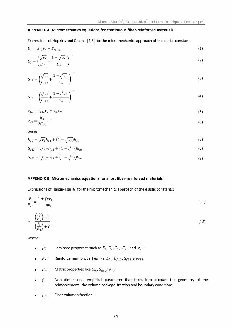
APPENDIX A. Micromechanics equations for continuous fiber-reinforced materials
Expressions of Hopkins and Chamis [4,5] for the micromechanics approach of the elastic constants:
(1)
(2)
(3)
(4)
(5)
(6)
being
(7)
(8)
(9)
APPENDIX B. Micromechanics equations for short fiber-reinforced materials
Expressions of Halpin-Tsai [6] for the micromechanics approach of the elastic constants:
(11)
(12)
where:
: Laminate properties such as and .
: Reinforcement properties like .
: Matrix properties like .
: Non dimensional empirical parameter that takes into account the geometry of the reinforcement, the volume package fraction and boundary conditions.
: Fiber volumen fraction .
279
Influence of micromechanics in composite panels buckling loads Third International Conference on Mechanical Models in Structural Engineering University of Seville. 24-26 june 2015.
REFERENCES
[1] Bank, L.C. (2006). Composites for Construction - Structural Design with FRP Materials, John Wiley & Sons, Inc.
[2] Rikards, R., Chate, A. y Ozolinsh, O.(2001). Analysis for buckling and vibrations of composite stiffened shells and plates. Composite Structures, 51, pp. 361-370.
[3] Mallela, U.K. y Upadhyay, A.(2006). Buckling of laminated composite stiffened panels subjected to in-plane shear: A parametric study. Thin-Walled Structures, 44, pp. 354-361.
[4] Kollar, L.P. y Springer, G. S.(2009). Mechanics of Composite Structures. Cambridge University
Press.
[5] Hopkins, D.A., Chamis, C.C.A. (1988). Unique set of micromechanics equations for high temperature metal matrix composites. In: Testing Technology of Metal Matrix Composites, ASTM STP 964. American Society for Testing and Materials, Philadelphia, pp. 159-176.
[6] Tucker, C. L. y Liang, E. (1999). Stiffness predictions for unidirectional short-fiber composites: Review and evaluation. Composite Science and Technology, 59, pp. 655-671.
[7] Kaddour, A.S., Hinton, M. J. (2012). Input data for test cases used in benchmarking triaxial failure theories of composites, Composite Materials, 54, pp. 2295-2312.
[8] Maurin, R., Davies, P., Baral, N. Baley, C. (2008). Transverse Properties of Carbon Fibres by Nano-Indentation and Micromechanics, Applied Composite Materials, 15, pp. 61-73.
280