Embed Size (px)
Citation preview

Coupled Systems Mechanics, Vol. 5, No. 2 (2016) 127-144
DOI: http://dx.doi.org/10.12989/csm.2016.5.2.127 127
Copyright © 2016 Techno-Press, Ltd.
http://www.techno-press.org/?journal=csm&subpage=7 ISSN: 2234-2184 (Print), 2234-2192 (Online)
Influence of interface on the behavior of infilled frame subjected to lateral load using linear analysis
K. Senthil1 and K.S. Satyanarayanan2
1National Institute of Technology Jalandhar, Punjab 144011, India
2SRM University, Kattankulathur, Kancheepuram, TamilNadu 603203, India
(Received March 19, 2016, Revised May 9, 2016, Accepted May 10, 2016)
Abstract. Two dimensional numerical investigations were carried out to study the influence of interface thickness and their pattern on the behavior of reinforced concrete frames subjected to in-plane lateral loads using commercial finite element tool SAP 2000. The linear elastic analysis was carried out on one and two bay structural systems as well as the influence of number of stories was studied by varying the number of stories as single, three and five. The cement mortar was used as interface material and their effect was studied by varying thicknesses as 6, 8, 10, 14 and 20 mm. The interface was recognized as one sided, two sided, three sided and four sided and their effect was studied by removing the interface material between the reinforced concrete frame and masonry infill. The effect of lateral loads on infill masonry wall was also studied by varying assumed loads as 10, 20, 30, 40, 50 and 60 kN. The behavior of infilled frames studied has revealed that there is a maximum influence of interface thickness and interface pattern corresponding to 10 mm thickness. In general, the lateral displacement of frame is increased linearly with increase in lateral loads.
Keywords: finite element method; interface thickness; interface pattern; in-plane lateral loads; maximum
principal stress
1. Introduction
Recent earthquakes in Nepal (2015), Bhuj (2001), Turkey (Kocaeli 1999, Duzce1999, Bingol
2003) have demonstrated large seismic demands that were not accounted for in their design. Most
of the weakest spot of the building are reinforced concrete frame element and infill masonry wall
element which in spite of bonding layers of interface element. The post-earthquake reconnaissance
surveys showed (Dogangun et al. 2008) the lack of lateral strength together with masonry infill,
frame element and interface element for collapse in most cases. According to Erdik and Aydınoglu
(2003), in urban areas, 30% buildings were reinforced concrete frame, 48% were brick masonry
and 22% were adobe or rubble masonry. In rural areas, 82% of buildings were brick masonry
while 18% were reinforced concrete frame. Therefore, the safety of the masonry building is very
important in the moderate to severe seismic zones, as 90% of the world population lives and works
in masonry buildings and these buildings should be protected during earthquakes.
Corresponding author, Assistant Professor, E-mail: [email protected]

K. Senthil and K.S. Satyanarayanan
Girish and Achyutha (1996) performed experimental and analytical investigation on the
response of reinforced cement concrete bare and non-integral brick masonry infilled frames under
lateral reversed cyclic loads. They found that the infill-frame interaction is found to enhance the
base shear capacity, improve the hysteretic behavior and alter the failure mode of the bare frame.
Mehrabi and Singh (1997) have carried out experimental and analytical studies on
masonry-infilled reinforced concrete frames under in-plane lateral loadings. A smeared-crack finite
element model was used to model the behavior of concrete in the RC frames and masonry units.
Authors concluded that the finite element models are able to simulate the failure mechanisms
exhibited by infilled frames including the crushing and cracking of the concrete frames and
masonry panels and the sliding and separation of the mortar joints. Ghosh and Amde (2002)
formulated a non-associated interface models using the available test data on masonry joints to
model the interface between the frame and the infill and the mortar joints surrounding the blocks
of masonry. The results obtained by the finite element model showed that the numerical model not
only is capable of predicting the load carrying capacities of infilled frames, but can also provide
detailed information on the failure mode, ductility, and cracking, which can be of much value in
evaluating the seismic resistance of in- filled frames. Anil and Altin (2006) conducted
experimental investigations on partially infilled one-bay one-storey reinforced concrete frames
under reversal cyclic load. The pushover analysis was also carried out using IDARC-2D to
compare the ultimate strength of the infilled frame and resulted in slightly higher initial stiffnesses
for the infilled specimens than the experimental values. Authors concluded that the monolithically
infilled specimen showed 7 times more energy dissipation capacity than the bare frame. Asteris
(2008) presented a simple method to simulate the complicated behavior of infilled frames under
lateral loads. The proposed analytical method calculates the infill contact lengths as an integral
part of the solution. Especially this technique calculates the infill/frame contact lengths for the case
of unidirectional lateral loading and elastic response of the infill. The authors concluded that the
proposed technique is easier and more practical to apply, and requires much less computational
time than micro-modeling techniques based on discretizing the infill panel as a series of plane
stress elements interconnected by a series of springs or contact elements. Mondal and Jain (2008)
carried out finite element analysis on single-bay single-storey, single-bay two-storey, and
single-bay three-storey infilled frames to examine the effect of central openings of different sizes
on the initial lateral stiffness of infilled frames. Authors concluded that the effect of opening on the
initial lateral stiffness of infilled frames should be neglected if the area of opening is less than 5%
of the area of the infill panel, and the strut-width reduction factor should be set to one, i.e., the
frame is to be analyzed as a solid infilled frame. The effect of infill on the initial lateral stiffness of
infilled frame may be ignored if the area of opening exceeds 40% of the area of the infill panel,
and the strut-width reduction factor should be set to zero, i.e., the frame is to be analyzed as a bare
frame. Eshghi and Pourazin (2009) performed numerical investigation on full scale confined
masonry wall with and without opening based on static nonlinear analysis under in plane loading
using finite element tool DIANA. They found that the ultimate deformation capacity of the wall
with opening is about 1/10 ultimate deformation capacity of the wall without opening. Okail et al.
(2014) conducted experiments and numerical investigations on six full-scale confined masonry
walls subjected to lateral loads. Authors found that the experimental results showed that the walls
in general experienced a shear failure at the end of the lightly reinforced confining elements after
the failure of the diagonal struts formed in the brick wall due to transversal diagonal tension. The
numerical results showed acceptable correlation and were used to conduct a thorough parametric
study on various design configurations. Abdel-Hafez et al. (2015) conducted experiments on single
128

Influence of interface on the behavior of infilled frame subjected to lateral load using linear analysis
storey bare frame, brick masonry infilled frames strengthened with glass fiber reinforced polymer
(GFRP) sheets, steel rebar impeded in frame, plastering and ferrocement meshes studied under the
in-plane lateral load. Authors found that the drift, toughness, ductility and failure load were
improved by using such masonry wall due to like-shear wall effect which also increased frame
capacity to resist lateral load. The ductility of infilled frame strengthened with Ferro cement was
the best of all strengthened frames, while strengthening with GFRP increases its ultimate load
carrying capacity but reduces its ductility. Khoshnoud and Marsono (2016) developed a simple
method, called corner opening, by replacing the corner of infill walls with a very flexible material
to enhance the structural behavior of walls. To evaluate the proposed method a series of
experiments were conducted on masonry infill wall and reinforced concrete frames with and
without corner openings. The experimental results revealed that the proposed method reduced the
strength of infill wall specimens but considerably enhanced the ductility of infill wall specimens in
the diagonal tension test. The authors have also found that the corner opening in infill walls
prevented the sliding shear failure of the infill wall in RC frames with infill walls. In addition to
that many studies found on masonry infilled reinforced concrete, non-ductile frames, different type
of infill under seismic loadings, [Klingner and Bertero (1978), Buonopane and White (1999),
Al-Chaar et al. (2002), Kaushik et al. (2006) and, Leite and Lourenco (2010)] and finite element
modeling, [Ibrahimbegovic (1990), Ibrahimbegovic et al. (1990) and Ibrahimbegovic and Wilson
(1991)].
The review of literature carried out has indicated that study on effect of interface of frame and
infill as well as influence of interface pattern and different interface thickness is limited. An
attempt is made in this study to quantify the effect of interface patterning of infill wall on the
behavior of frames with respect to lateral stiffness and maximum infill stress. One of the
construction difficulties is to ensure uniform thickness of the mortar joints. In some cases the
frame to infill joining is so ineffective that one may consider that it is totally absent. The
interaction between frame and infill is through the interface and any such variation or
non-uniformity or absence can lead to ineffective infilled frame action. Hence, it is significant to
study the effect of such variation on the infilled frame behavior. Also an attempt is made in this
study to quantify the effect of lateral stiffness on the behavior of one storey, three storey and five
storey as well as single bay and two bay frames.
2. Analytical investigation
Analytical models that have been developed to quantify the effect of interface thickness and
effect of interface pattern on the frames are proposed to carry out an analytical investigation as
outlined in this Section. In the investigation linear elastic analysis is carried out and the geometric
details of the frame are shown in Table 1. According to Indian Standard 13920:1993, the minimum
dimension of the member shall not be less than 200 mm. However, in frames which have beams
with Centre to Centre span exceeding 5 m or columns of unsupported length exceeding 4 m, the
shortest dimension of the column shall not be less than 300 mm. In addition to that, most of the
residential buildings have room sizes and height approximately 3 m and lateral dimensions are
0.23 - 0.30 m. Therefore, the length and height of the frame was 3.0 m while cross section of the
beam and column was 0.3 x 0.3 m considered in the present study. The interaction between the
frame and the infill due to applied load plays important role in the behavior of the infilled frames.
In most applications, the infill is connected to the frame by mortar, see Fig. 1. Since the connection
129

K. Senthil and K.S. Satyanarayanan
of link elements and masonry infill, interface elements are enabled to take tension and shear forces,
the interaction between the frame and the infill through this mortar joint is modeled by an interface
element capable of transferring normal and shear forces in the elastic and inelastic ranges of
loading. The interface as well as infill elements are modeled as a shell elements considered as a
plane stress type. In the finite element modeling of the infilled frame, the modeling of the interface
between the infill and the frame has been given the prime emphasis.
Finite element modeling of bare frame and infilled frame has been shown in Figs. 2(a) and 2(b)
respectively, using SAP 2000 Version 15. In the parametric study, five parameters, i.e., interface
thickness, interface pattern, lateral loads, number of storeys and number of bays are considered.
For this purpose, the interface element thicknesses were assigned as 6 mm, 8 mm, 10 mm, 14 mm
and 20mm. The cement mortar was used as interface material and their effect was studied by
varying thicknesses as 6, 8, 10, 14 and 20 mm. The interface was recognized as one sided, two
sided, three sided and four sided and their effect was studied by removing the interface material
between the reinforced concrete frame and masonry infill. For instance, the side 2, side 3 and side
4 was removed, marked as “None”, see Fig. 2(b) and side 1 was showing “Interface” since it was
modeled as one sided interface and vice versa. The cement mortar and masonry infill are clearly
shown in Fig. 2(c).
Table 1 Geometric details of reinforced concrete systems
Particulars Details, mm
Bay width 3000
Ground floor and typical floor height 3000
Beam dimension 300 300
Column dimension 300 300
Infill panel thickness 300
Fig. 1 Conventional masonry infilled reinforced concrete frame with interface
130

Influence of interface on the behavior of infilled frame subjected to lateral load using linear analysis
The four interface sides left, top, right and bottom side of the frame are illustrated by side 1,
side 2, side 3 and side 4. The fully interface infilled frame labeled as four sided interface. The
lateral load on infill frame was varied as 10, 20, 30, 40, 50 and 60 kN and the effect was studied.
The lateral load considered in the present study was arbitrary. Six sets of reinforced concrete
infilled frames, namely single-bay single-storey, single-bay three-storey, and single-bay five-storey,
two-bay single-storey, two-bay three-storey, and two-bay five-storey were analyzed and their
lateral displacement and infill stress was predicted by linear elastic analysis. Thus a total of 435
models were analyzed in the parametric study. The critical cases are decided on the basis of
highest percentage of variation influenced due to the interface pattern and interface thicknesses are
presented here. In the present study, authors are concerned that the knowledge of the elastic
response of composite structure is very critical for a thorough understanding of its response under
monotonic/cyclic loading. For this reason, the research paper concentrates on the elastic domain of
the analysis.
The linkage elements were used to connect the weak interface elements and the surrounding
concrete frame, see Fig. 2(b). A link element was used to connect two joints, separated by
thickness or width of interface, such that specialized structural behavior was modeled. The
linear properties were assigned to link elements such that directional properties of U1, U3 and R2
are restrained. Based on the developed forces in these linkage elements, separation between infill
and frame was assumed to occur.
Fig. 2 Schematics of (a) bare frame (b) infilled frame with interface at only one side (one sided) (c)
cement mortar
131

K. Senthil and K.S. Satyanarayanan
Fig. 3 Typical load application on (a) single (b) three and (c) five storey
The frame elements were modeled as beam and column elements, while the infill and interface
elements were modeled as shell elements with plane sections. In the frame element such as beam
and columns elements, auto meshing at intermediate points was specified by default. The infill and
interface elements (Cement Mortar) were shell elements and discretized as area mesh through auto
meshing. The boundary conditions were assigned as a fixed joint and zero displacement was
specified for fixed degree of freedom at restraint support locations. The compressive strength of
brick masonry at 28 days is 4.6 MPa [Rai 2005 and New Zealand Concrete Masonry Manual
(2011)] roughly equal to 5 MPa was considered for the analysis and concrete having a
characteristic compressive strength of 20 MPa was used and the properties are shown in Table 2.
For concrete, the modulus of elasticity is taken as that recommended by IS 456:2000, that is
5700√𝑓𝑐𝑘 MPa where 𝑓𝑐𝑘characteristic compressive strength of 20 MPa is. Poisson’s ratio of
interface and concrete was taken as 0.15 commonly adopted for the design. For cement mortar, the
modulus of elasticity and Poisson’s ratio are taken as 10000 MPa and 0.15, respectively, Yang et al.
(1996). For masonry, the modulus of elasticity and Poisson’s ratio are taken as 6300 MPa and 0.15,
respectively, Dhanasekhar and Page (1986). Therefore, the modulus of elasticity and Poisson’s
ratio are approximately taken as 5000 MPa and 0.15, respectively considered in the present study.
All the models were analyzed by applying lateral load in combination with gravity load. The
frames were loaded at storey level at the top left corner with 10 kN lateral forces as point load, see
Fig. 3.
In the present study, node element model has been used to discretize the beam and column
element whereas finite element model is used for infill and interface. Node element model in
132
Influence of interface on the behavior of infilled frame subjected to lateral load using linear analysis
structural elements are represented by individual lines connected by nodes. The size of mesh used
in beam and column elements is 0.375 m. A node element model is technically a finite-element
model in which a single line element represents the structural element, (SAP 2000). Node element
modeling, however, follows the direct stiffness method, whereas finite element modeling follows
the finite element method. Finite element model with a meshing procedure creates a network of
line elements connected by nodes within a material continuum. The number of elements are 20
20 and 2 2 used as infill and interface elements, respectively.
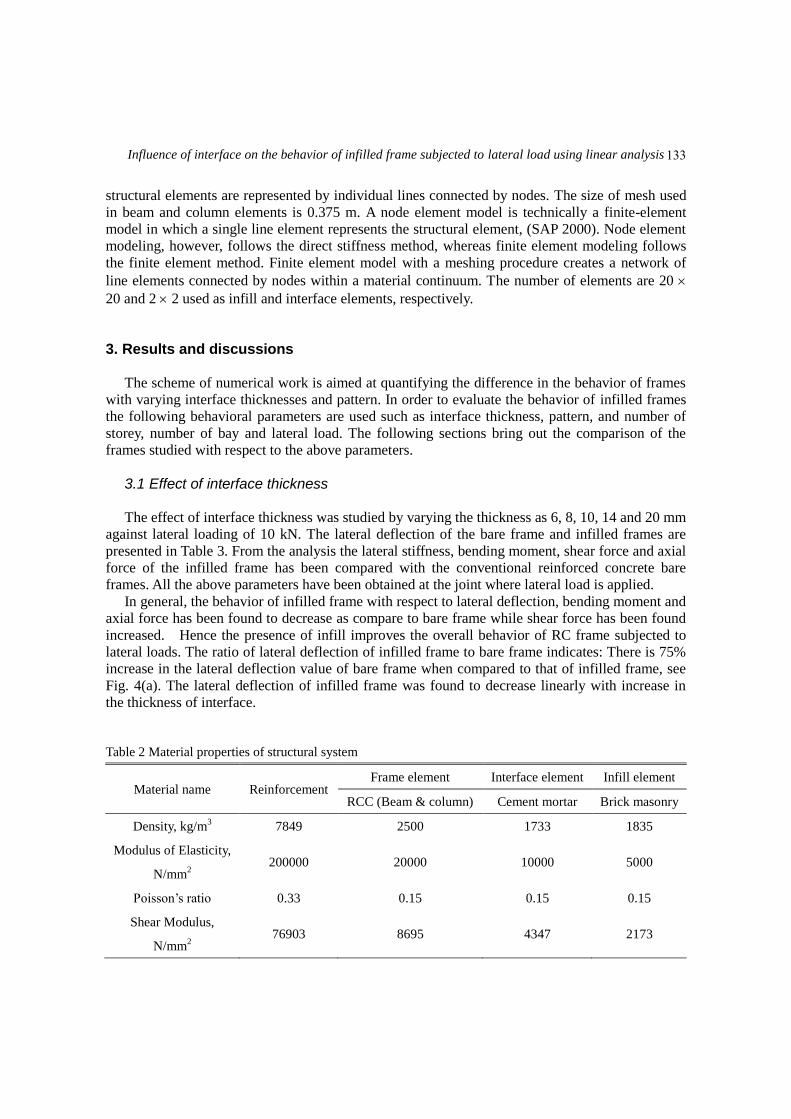
3. Results and discussions
The scheme of numerical work is aimed at quantifying the difference in the behavior of frames
with varying interface thicknesses and pattern. In order to evaluate the behavior of infilled frames
the following behavioral parameters are used such as interface thickness, pattern, and number of
storey, number of bay and lateral load. The following sections bring out the comparison of the
frames studied with respect to the above parameters.
3.1 Effect of interface thickness
The effect of interface thickness was studied by varying the thickness as 6, 8, 10, 14 and 20 mm
against lateral loading of 10 kN. The lateral deflection of the bare frame and infilled frames are
presented in Table 3. From the analysis the lateral stiffness, bending moment, shear force and axial
force of the infilled frame has been compared with the conventional reinforced concrete bare
frames. All the above parameters have been obtained at the joint where lateral load is applied.
In general, the behavior of infilled frame with respect to lateral deflection, bending moment and
axial force has been found to decrease as compare to bare frame while shear force has been found
increased. Hence the presence of infill improves the overall behavior of RC frame subjected to
lateral loads. The ratio of lateral deflection of infilled frame to bare frame indicates: There is 75%
increase in the lateral deflection value of bare frame when compared to that of infilled frame, see
Fig. 4(a). The lateral deflection of infilled frame was found to decrease linearly with increase in
the thickness of interface.
Table 2 Material properties of structural system
Material name Reinforcement Frame element Interface element Infill element
RCC (Beam & column) Cement mortar Brick masonry
Density, kg/m3 7849 2500 1733 1835
Modulus of Elasticity,
N/mm2
200000 20000 10000 5000
Poisson’s ratio 0.33 0.15 0.15 0.15
Shear Modulus,
N/mm2
76903 8695 4347 2173
133

K. Senthil and K.S. Satyanarayanan
Fig. 4 Influence on (a) Lateral deflection (b) bending moment (c) shear force and (d) axial force with
respect to interface thickness
Table 3 Comparison of parameters of bare frame and infilled frame
Particulars Bare frame Infilled frame with varying interface thickness (mm)
6 8 10 14 20
Lateral Deflection 1.381 0.3584 0.3306 0.3215 0.3091 0.3032
Bending Moment 6.31 1.983 1.906 1.882 1.84 1.817
Shear Force 5.02 5.250 5.247 5.247 5.247 5.229
Axial Force 4.975 4.744 4.752 4.752 4.752 4.770
0.27
0.3
0.33
0.36
0.39
6 8 10 14 20
Lat
eral
Dis
pla
cem
ent
(mm
)
Interface Thickness (mm)
1.7
1.77
1.84
1.91
1.98
6 8 10 14 20B
end
ing M
om
ent
(kN
m)
Interface Thickness (mm)
5.215
5.225
5.235
5.245
5.255
6 8 10 14 20
Shea
r F
orc
e (k
N)
Interface Thickness (mm)
4.73
4.74
4.75
4.76
4.77
6 8 10 14 20
Axia
l F
orc
e (k
N)
Interface Thickness (mm)
(a) (b)
(c) (d)
134

Influence of interface on the behavior of infilled frame subjected to lateral load using linear analysis
The lateral displacement of infilled frame with 6, 8, 10, 14 mm interface was found increased
by 18, 9, 6 and 2% as compare to 20 mm interface thickness. Similarly, the bending moment of
infilled frame with 6, 8, 10, 14 mm interface was found increased by 9, 5, 3.5 and 1.2% as
compare to 20 mm interface thickness. The bending moment of bare frame to infilled frame is
decreased by 70%, see Fig. 4(b) whereas the influence on shear and axial force was found same for
interface thickness 14 mm.
For interface thickness 20 mm, the shear force was found dropped and axial force was found
jumped, see Fig. 4(c) and 4(d). The shear force drop was found very nominal, 5.247 to 5.229 MPa.
It may be due to the friction at interface, affecting the behavior of infilled frame. Also the axial
force increased because of shear, the reason may be the same. The shear force on the bare frame
obtained from the simulation was taken as 5.02 kN by left side column and 4.98 kN by right side
column. When the infilled frame is subjected to horizontal load, the infill and the frame separate
over the region where tension occurs and remain in contact where compression occurs. The effect
of this interaction reduces the lateral displacement of the frame and improves its lateral strength
and it reduces the bending moment. Hence the design becomes economical though the axial force
is increased, see Fig. 4(d).
The maximum principal stress at interface and masonry infill was shown in Fig. 5. The
maximum principal stress decreased as 1.05, 0.91, 0.77, 0.63 and 0.49 N/mm2 corresponding to
interface thickness varied as 6, 8, 10, 14 and 20 mm. The highest maximum principal stress was
observed at top left and bottom right corners. The maximum principal stress observed at cement
mortar interface is not visible because the thickness of interface is very small as compared to width
of masonry infill. The decrement in the interface stress on 8, 10, 14 and 20 mm as compared to the
stress on 6 mm interface thickness was found as 13.3, 26.6, 40 and 53%.
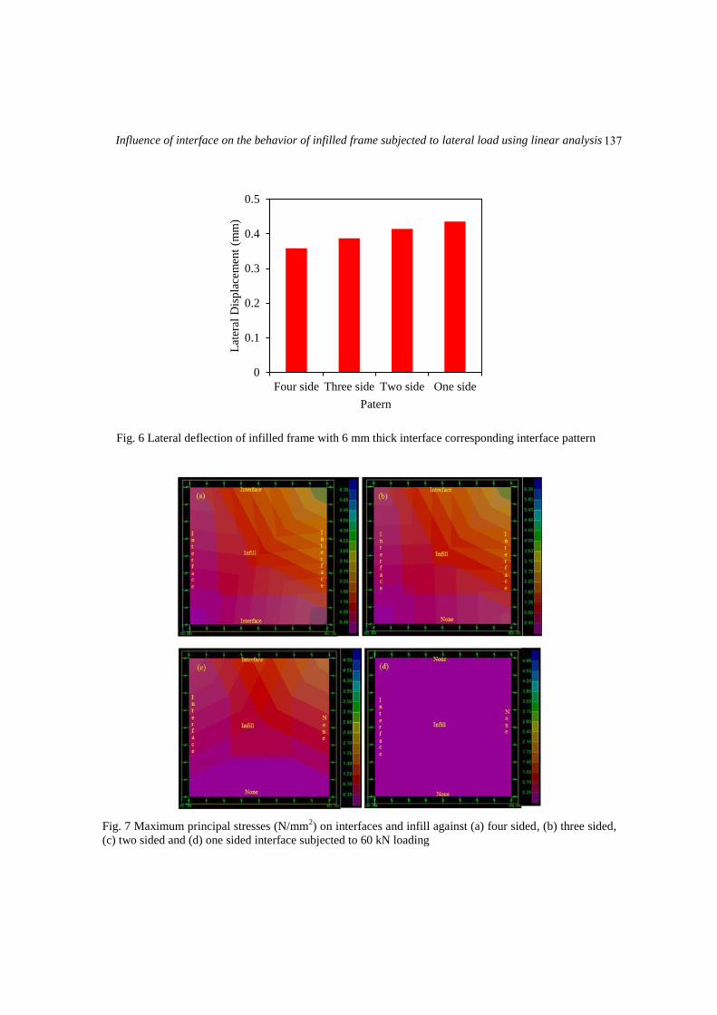
3.2 Effect on interface pattern
As discussed in Section 2, the interface pattern are classified as one sided, two sided, three
sided and four sided and it is designated by removing the interface material between the reinforced
concrete frame and masonry infill. The lateral load on infill frame was also varied as 10, 20, 30, 40,
50 and 60 kN. The lateral displacement of infilled frame with 6 mm interface thickness on four
sided, three sided, two sided and one sided against 10 kN is shown in Fig. 6. The lateral
displacement of three sided, two sided and one sided interface infilled frame was found increased
to 8, 15 and 22% as compared to fully infilled frame. Hence, the composite in-plane action of the
wall and the frame renders the structure very stiff and strong; however the ductility of frame is
lowered during failure. The stiffness of an infilled frame is dependent on the separate stiffness of
the frame and infill panel and on the way which they interact at the interface of the two. The
displacements on 6, 8, 10, 14 and 20 mm thick one sided interface frame have been found as
0.4356, 0.4257 0.4206, 0.4236 and 0.5109 mm respectively. The resistance of the frame was
found maximum with the interface thickness 10 mm and corresponding lateral displacement was
0.4206 mm. Therefore, it is concluded that the maximum influence of interface thickness and
maximum influence of interface pattern corresponding to 10 mm thickness of interface was found
effective. Also the displacement on bare frame and infilled frame with 10 mm thick one sided
interface was found 1.381 and 0.42 mm, respectively.
135

K. Senthil and K.S. Satyanarayanan
Fig. 5 Maximum principal stresses (N/mm2) on interface and masonry infill against (a) 6 mm, (b) 8 mm,
(c) 10 mm, (d) 14 mm and (e) 20 mm thick interface thickness
136
Influence of interface on the behavior of infilled frame subjected to lateral load using linear analysis
Fig. 6 Lateral deflection of infilled frame with 6 mm thick interface corresponding interface pattern
Fig. 7 Maximum principal stresses (N/mm2) on interfaces and infill against (a) four sided, (b) three sided,
(c) two sided and (d) one sided interface subjected to 60 kN loading
0
0.1
0.2
0.3
0.4
0.5
Four side Three side Two side One side
Lat
eral
Dis
pla
cem
ent
(mm
)
Patern
137

K. Senthil and K.S. Satyanarayanan
Fig. 8 Maximum principal stresses (N/mm2) on interfaces occurred due to one side interface
3.3 Effect on number of storey
Three sets of reinforced concrete infilled frames, namely single-bay single-storey, single-bay
three-storey, and single-bay five-storey were analyzed. The lateral displacement and infill stress of
infilled frame with four sided interface (fully infilled frame) was predicted by linear elastic
analysis. The lateral deflection of one, three and five storey was 0.3584, 1.4164 and 3.272 mm
respectively against 10 kN loading. The maximum principal stresses on interfaces and masonry
infill of three and five storey frame against 10 kN loading have been shown in Fig. 9(i). Similarly,
the maximum principal stresses on three and five storey frame against 60 kN loading have been
shown in Fig. 9(ii). The bounding frame acts as tie and strut member and the infill acts like an
inclined diagonal strut member, see Fig. 9(b) at second and fifth floor.
Ghosh and Amde (2002) conducted the finite element analysis on infilled frame with different
relative frame-infill strength have been compared with the experiments performed by Riddington
(1984). Riddington (1984) carried out experiments on flexible frame (column and beam) was made
152 x 152 x 30 mm wide flange section with 2710 x 2710 mm infill. The frames were formed from
Grade 43 rolled steel sections welded together at the frame corners. The compressive strength of
infill was 7 N/mm2 made by masonry cement and sand mortar. The Modulus of elasticity and the
Poisson’s ratio of the masonry infill were 15400 N/mm2 and 0.15, respectively. The finite element
model by Ghosh and Amde (2002) includes interface elements in between frame and masonry
infill. The interaction between the frame and the infill through this mortar joint is modeled by an
interface element capable of transferring normal and shear forces in the elastic and inelastic ranges
of loading. The thickness of interface element was set to an infinitesimally small value. They
predicted the failure mode and the minimum principal stress on infill flexible frame against 216
kN lateral load, which is shown in Fig. 10(a) and these plots show that the infill stress is very high
138

Influence of interface on the behavior of infilled frame subjected to lateral load using linear analysis
at the corners, 11,600 kN/m2 and similar results were predicted in the present study as shown in
Fig. 10(b) and the stress at the corners is 1500 kN/m2 corresponding to lateral load of 60 kN.
Fig. 9 Maximum principal stresses (N/mm2) on interfaces and masonry infill of (a) three and (b) five
storey frame against (i) 10 kN and (ii) 60 kN loading
Fig. 10 Minimum principal stresses (kN/m2) on infill from (a) results by Ghosh and Amde (2002) and (b)
present study
139

K. Senthil and K.S. Satyanarayanan
When the infilled frame is subjected to horizontal load, the infill and the frame separate over
the region where tension occurs and remain in contact where compression occurs, see Fig. 11(a).
The maximum principal stress at infill of junction 2 and 4 was found maximum, 1500 kN/m2, see
Fig. 11(b). The maximum principal stress on interface seems to be zero stress at junction 1 and 3
due to the infill and RC frame separated over the region where the tension influenced by the lateral
load, see Fig. 11(c). The principal stress on interface seems to be maximum (1500 kN/m2) stress at
junction 2 and 4 due to the infill and RC frame slip occurs over the region where the compression
influenced by the lateral load, see Fig. 11(c). In the present study, proper separation or slip could
not be predicted through simulations.
Fig. 11 Strut action of (a) schematic, (b) maximum principal stress (kN/m2) on infill and (c) maximum
principal stress (kN/m2) on interface
140

Influence of interface on the behavior of infilled frame subjected to lateral load using linear analysis
Fig. 12 Maximum principal stresses (N/mm2) on interfaces and masonry infill of (a) one bay and (b) two
bay frame against (i) 10 kN and (ii) 60 kN loading
3.4 Effect on number of bay
The finite element analysis has been carried out on single bay-single storey and two bay- single
storey against in-plane lateral loading, see Figs. 12(a) and12(b). The resistance of the infilled
frame was obtained by varying lateral load as 10 kN and 60 kN. Lateral deflection of single
bay-single storey and two bay-single storey infilled frame is 0.3584 and 0.189 mm, respectively.
The maximum principal stresses 1.05 and 0.36 N/mm2on interfaces and masonry infill of single
and two bay frame respectively against 10 kN loading has been shown in Fig. 12(i). Similarly, the
maximum principal stresses 6.3 and 2.24 N/mm2on single and two bay frame respectively against
60 kN loading have been shown in Fig. 12(ii). Therefore it is concluded that two bay square
frames with equal areas of infill exhibit more lateral stiffness and reduces the stress in the infill
almost 70%.
3.5 Effect of lateral load
The effect of interface pattern, number of storey and number of bays was studied against
varying in-plane lateral loading, see Figs. 13(a)-13(c). The lateral load on infilled frame was
assumed as 10, 20, 30, 40, 50 and 60 kN. The lateral displacement of one, two, three and four
sided interface pattern frame against varying load is shown in Fig. 13(a), increased linearly with
increase in lateral loads. The lateral displacement of fully infilled frame, described by red solid
141

K. Senthil and K.S. Satyanarayanan
circle is lesser as compared to three, two and one sided interface of 6 mm thickness. Further, when
the lateral load was increased as 10, 20, 30, 40, 50 and 60 kN, the significant deviation was
observed between fully infilled frame and one sided infilled frame. The lateral deflection of fully
infilled frame and one sided interface frame due to 10 kN lateral load was found almost same as
0.35 and 0.43 mm, respectively while the lateral load was increased to 60 kN, 2.15 and 2.6 mm,
respectively. Therefore, the deviation between the fully infilled frame and one sided infilled frame
was found to be 0.08 and 0.45 mm with respect to 10 and 60 kN. The stiffness of the fully infilled
frame increased to 25% when compared to the one sided infilled frame against 60 kN. Therefore, it
is concluded that the interface pattern significantly affects the structural system when the lateral
load increased.
The lateral displacement of one, three and five storey infilled frame against varying load is
shown in Fig. 13(b), increased linearly with increase in lateral loads. The lateral deflection of
frame varied in the range of 2 – 20 mm as the number of storey varied upto five. The increment in
the lateral displacement was found steep on five storey frame as compared to three and single
storey frame. Similarly, the resistance of single bay and two bay frames was also studied against
varying load is shown in Fig. 13(c). The stiffness of two bay frame increased significantly and the
lateral deflection is reduced to 50% compared to single bay frame.
Fig. 13 Effect of (a) interface pattern, (b) number of storey and (c) number of bay by varying the lateral
load
142

Influence of interface on the behavior of infilled frame subjected to lateral load using linear analysis
4. Conclusions
The present numerical study describes the behavior of infilled frame subjected to lateral
in-plane load. The influence of the interface thickness, interface pattern, number of stories, number
of bays and lateral load was studied. The results thus obtained through finite element
investigations led to the following conclusions;
The resistance of the frame was found maximum with the interface thickness 10 mm therefore,
it is concluded that the maximum influence of interface thickness and maximum influence of
interface pattern corresponding to 10 mm thickness of interface was found effective. Also the
displacement on bare frame and infilled frame with 10 mm thick one sided interface was found
1.381 and 0.42 mm, respectively.
The lateral displacement of three sided, two sided and one sided interface to infill was
increased to 8, 15 and 22% as compared to fully infilled frame, respectively. The lateral deflection
of one, three and five storey has been obtained as 0.3584, 1.4164 and 3.272 mm respectively and
the infill acts like an inclined diagonal strut member as observed at second and fifth floor.
The lateral deflection of single bay-single storey and two bay- single storey infilled frame is
0.3584 and 0.189 mm respectively, while the maximum principal stresses reduced significantly
to1.05 and 0.36 N/mm2.
Also, it is concluded that two bay square frames with equal areas of infill exhibit more lateral
stiffness and reduce the stress in the infill by almost 70%. The stiffness of the fully infilled frame
increased to 25% when compared to the one sided infilled frame against 60 kN. Therefore, it is
concluded that the interface pattern significantly affects the structural system when the lateral load
increased.
Acknowledgements
The authors sincerely acknowledge the valuable support from Mrs. S.SanthanaSelvi and Dr. R.
Padma Priya for the successful completion of numerical investigations at SRM University,
Kattankulathur, Chennai.
References
Abdel-Hafez, L.M., Abouelezz, A.E.Y. and Elzefeary, F.F. (2015), “Behavior of masonry strengthened
infilled reinforced concrete frames under in-plane load”, Hous. Building Nat. Res. Center, 11, 213-223.
Al-Chaar, G., Issa, M. and Sweeney, S. (2002), “Behavior of masonry infilled non-ductile reinforced
concrete frames, J. Struct. Eng. – ASCE, 128, 1055–1063.
Anil, O. and Altin, S. (2007), “An experimental study on reinforced concrete partially infilled frames”, Eng.
Struct., 29, 449-460.
Asteris, P.G. (2008), “Finite element micro-modeling of infilled frames”, Elect. J. Struct. Engg., 8, 1-11.
Buonopane, S.G. and White, R.N. (1999), “Pseudodynamic testing of masonry-infilled reinforced concrete
frame” , J. Struct. Eng. - ASCE, 125(6), 578-589.
CSI (2000), “Integrated Software for Structural Analysis and Design: Analysis Reference Manual”,
Computer and Structures, Inc., Berkeley, CA.
Dhanasekhar, M. and Page, A.W. (1986), “The influence of brick masonry infill properties on the behavior
of infilled frames”, Proc. Inst. Civ. Eng., Part 2(81), 593-605.
143

K. Senthil and K.S. Satyanarayanan
Dogangun, A., Ural, A. and Livaoglu, R. (2008), “Seismic performance of masonry buildings during recent
earthquakes in turkey”, Proceedings of the 14th
World Conference on Earthquake Engineering, Beijing,
China, October 12-17.
Erdik, M. and Aydinoglu, N. (2003), “Earthquake vulnerability of buildings in Turkey”, Proceedings of the
3rd
International Symposium on Integrated Disaster Risk Management, Japan, July 3-5.
Eshghi, S. and Pourazin, K. (2009), “In-Plane behavior of confined masonry walls –with and without
opening”, Int. J. Civil Eng., 7(1), 49-60.
Ghosh, A.K. and Amde, A.M. (2002), “Finite element analysis of infilled frames” J. Struct. Eng. - ASCE,
128(7), 881-889.
Girish, K.B. and Achyutha, H. (1996), “Nonlinear finite element analysis of reinforced concrete frames with
brick masonry infill’s under lateral loads”, J. Struct. Eng. - ASCE, 22, 211-220.
Ibrahimbegovic, A. (1990) “A Novel membrane finite element with an enhanced displacement interpolation”,
J. Finite Elem. Anal. Des., 7, 167-179.
Ibrahimbegovic, A., Taylor, R.L. and Wilson, E.L. (1990), “A robust membrane quadrilateral element with
drilling degrees of freedom”, Int. J. Numer. Meth. Eng., 30, 445-457,
Ibrahimbegovic, A. and Wilson, E.L. (1991), “Thick shell and solid finite elements with independent
rotation fields”, Int. J. Numer. Meth. Eng., 31, 1393-1414.
IS 456 (2000), “Indian standard plain and reinforced concrete code of practice”, Bureau of Indian Standards,
New Delhi, India.
IS 13920 (1993), “Indian standard ductile detailing of reinforced concrete structures subjected to seismic
forces”, Bureau of Indian Standards, New Delhi, India.
Kaushik, H.B., Rai, D.C. and Jain, S.K. (2006) “Code approaches to seismic design of masonry infilled
reinforced concrete frames: A state-of-the-art review”, Earthq. Spectra, 22, 961-983.
Khoshnoud, H.R. and Marsono, K. (2016), “Experimental study of masonry infill reinforced concrete frames
with and without corner openings”, Struct. Eng. Mech., 57(4), 641-656.
Klingner, R.E. and Bertero, V.V. (1978), “Earthquake resistance of infilled frames”, J. Struct. Div. – ASCE,
104(6), 973-987.
Leite, J. and Lourenco, P.B. (2010), “On the Influence of masonry infills in concrete buildings”, Proceedings
of the 10th International Conference on Computational Structures Technology, Civil-Comp Press,
Stirlingshire, Scotland.
Mehrabi, A.B. and Singh, P.B. (1997), “Finite element modeling of masonry infilled RC frames”, J. Struct.
Eng. - ASCE, 123(5), 604-613.
Mondal, G. and Jain, S.K. (2008), “Lateral stiffness of masonry infilled reinforced concrete frames with
central opening”, Earthq. Spectra, 24(3), 701-723.
New Zealand Concrete Masonry Manual, (2011), “New Zealand Concrete Masonry Association”, Inc,
Section 3.4, Page 1-3.
Okail, H., Abdelrahman, A., Abdelkhalik, A. and Metwaly, M. (2014), “Experimental and analytical
investigation of the lateral load response of confined masonry walls”, Hous. Building Nat. Res. Center,
Doi:10.1016/j.hbrcj.2014.09.004.
Rai, D.C. (2005), “Review of design codes for masonry buildings” Report IITK-GSDMA-EQ10-V1.0. A –
Earthquake Codes. Indian Institute of Technology (Kanpur): Department of Civil Engineering.
Riddington, J.R. (1984), “The influence of initial gaps on infilled frame behavior”, Proc. Inst. Civ. Eng., Part
2(77), 295-310.
Yang, C.C., Lin, Y.Y. and Hung, R. (1996), “Elastic modulus of concrete affected by elastic moduli of mortar
and artificial aggregate”, J. Mar. Sci. Technol., 4(1) 43-48.
144