Embed Size (px)
Citation preview

Physica C 407 (2004) 153–159
www.elsevier.com/locate/physc
Influence of heat-treatment schedules on the transportcurrent densities of long and short segments
of superconducting MgB2 wire
Mohit Bhatia a,*, M.D. Sumption a, Mike Tomsic b, E.W. Collings a
a Department of Materials Science and Engineering, LASM, Ohio State University, 477 Watts Hall, 2041 College Road,
Columbus, OH 43210, USAb Hyper Tech Research Inc., Troy, OH 45373, USA
Received 7 March 2004; received in revised form 15 April 2004; accepted 19 April 2004
Abstract
Various MgB2/sheath composite strands have been tested using transport and magnetic measurement techniques.
The strands had bimetallic sheaths of (1) Fe/monel, (2) Fe/Cu and (3) Cu/Cu. In strands (1) and (2) the Fe played the
role of diffusion barrier. Transport current densities of more than 5· 105 A/cm2 at 4.2 K in self-field and 2.7· 104 A/cm2
at 5 T were obtained on short lengths of Fe/monel strand. In coils, 6· 104 A/cm2 in 1 T at 4.2 K for Cu/Cu sheath
strands and 2.2· 105 for Fe/monel sheath strands have been measured. The strands had diameters of 0.8–1.1 mm and
superconducting fractions ranging from 27% to 40% of the total wire cross-section. They were heat-treated (HT) at
temperatures of from 675 to 900 �C under various heat-treatment schedules. The best results were obtained at 675 �Cfor Cu/Cu and 700 �C for Fe/monel strands.
� 2004 Elsevier B.V. All rights reserved.
1. Introduction
Practical applications of MgB2 superconductors
require the fabrication of dense wires (both mono
and multi-filament) with high current densities at
the desired operating temperatures. For MgB2
wires, the sheath material (barrier and outer
sheath) plays a very important role in determiningthe transport properties. This work is a compara-
tive study between the use of double Fe/monel, Cu/
Cu and Fe/Cu sheaths in the fabrication of MgB2
* Corresponding author. Tel.: +1-614-6885344; fax: +1-614-
6883677.
E-mail address: [email protected] (M. Bhatia).
0921-4534/$ - see front matter � 2004 Elsevier B.V. All rights reserv
doi:10.1016/j.physc.2004.05.013
wires. We report magnetic and transport current
density measurements performed after heat-treat-
ment using various schedules.
2. Fabrication of the wires
2.1. Powder and strand fabrication
The strands studied were of the monocore
powder-in-tube (PIT) type, manufactured using a
continuous tube forming and filling (CTFF)
method by Hyper Tech Research Inc. (HTR). A
stoichiometric mixture of Mg (99.86% pure, fine)
and B (‘‘amorphous’’) powders were mixed in a ‘V’
shaped jarand then planetary milled in a Fritcsh
ed.

154 M. Bhatia et al. / Physica C 407 (2004) 153–159
planetary mill, model LC106A. A ball to powder
ratio of 1.7:1 by mass was used.
After milling the powder was dispersed onto thin
metal strip (either Fe or Cu) formed into a tube
during filling. This CTFF powder filled tube was
then inserted into either one or two outer sheathtubes and drawn to final size. Fig. 2(a) and (b) show
the cross-sections of the double Fe barrier monel
sheath (Fe/Fe/M) wire and the Cu/Cu sheath wire.
The wires tested had diameters of 0.8–1.1 mm.
2.2. Double iron/monel sheathMgB2 wire (Fe/Fe/M)
These strands consisted of CTFF (Mg+B)/Fe inserted into single wall Fe-tubes, 12 mm
thickness, and again into a monel outer sheaths
Table 1
Fe/Fe/monel, Fe/Cu, Cu/Cu short sample specifications
Sample name Reference name Dia., m
Fe/Fe/monel sheath samples
FeFeM750-60a MWJ17 1.14
FeFeM700-30 MWJ16 0.984
FeFeM700-60 MWJ15 0.984
FeFeM750-120 MWJ14 0.984
FeFeM750-60b MWJ13 0.984
FeFeM750-30 MWJ12 0.984
FeFeM750-15 MWJ11 0.984
FeFeM850-15 MWJ10 0.984
FeFeM850-05 MWJ09 0.984
FeFeM725-240 MWJ08 0.984
FeFeM650-60 MWJ07 1.14
FeFeM650-60 MWJ06 0.984
FeFeM900-00a MWJ05 0.984
FeFeM900-05a MWJ04 0.984
FeFeM900-00b MWJ03 1.14
FeFeM900-05b MWJ02 1.1.4
FeFeM900-15 MWJ01 1.14
Fe/Cu sheath samples
FeCu675-15a MWJ36 1.038
FeCu675-15b MWJ37 1.038
FeCu700-05a MWJ39 1.038
FeCu700-05b MWJ40 1.038
FeCu700-15a MWJ42 1.038
FeCu700-15b MWJ43 1.038
Cu/Cu sheath samples
CuCu675-15 MWJ21 1.038
CuCu700-05 MWJ27 1.038
CuCu700-15 MWJ32 1.038
CuCu725-05 MWJ24 1.038
and drawn down to a final diameter of about
1 mm.
2.3. Iron/copper sheath MgB2 wires (Fe/Cu)
The Fe/Cu standard PIT-process wires weremade by loading milled powders into a 0.12 mm
wall thickness Fe tube inserted into a fully hard
Cu-101 tube and drawn down to the final diame-
ters of about 1 mm.
2.4. Copper/copper sheath MgB2 wire (Cu/Cu)
The Cu/Cu monocore wires consisted of CTFF(Mg+B)/Cu (annealed Cu-101, 0.25 mm thick)
inserted into a full hard Cu 101 tube (9.5 mm
m Heat-treatment,
�C/minSC area, mm2
750/60 0.306
700/30 0.228
700/60 0.228
750/120 0.228
750/60 0.228
750/30 0.228
750/15 0.228
850/15 0.228
850/05 0.228
725/240 0.228
650/60 0.228
650/60 0.228
900/IN 0.228
900/05 0.228
900/IN 0.306
900/05 0.306
900/15 0.306
675/15 0.286
675/15 0.286
700/05 0.286
700/05 0.286
700/15 0.286
700/15 0.286
675/15 0.286
700/05 0.286
700/15 0.286
725/5 0.286

M. Bhatia et al. / Physica C 407 (2004) 153–159 155
OD · 7.75 mm ID) and drawn down to a final
diameter of approximately 1 mm. All the wires
so produced were then heat-treated in flowing Ar at
Time, t (mins)
0 20 40 60 80 100
Tem
pera
ture
, T (
o C)
0
100
200
300
400
500
600
700
800
750oC / 30 mins 675 oC /15 min
Fig. 1. T vs t for the HT of wires.
Table 2
Fe/Fe/monel and cu/cu long sample specifications
Sample name Dia., mm Heat-treatment,
�C/minSC area,
mm2
Cu/Cu sheath samples
CuCu675-15L 1.038 675/15 0.286
Fe/Fe/monel sheath samples
FeFeM700-30L 0.984 700/30 0.228
Fig. 2. Cross-section of monofilamentary
various time–temperature schedules (Tables 1 and
2). Heat-treatment profiles are shown in Fig. 1.
3. Measurements
3.1. Transport current density measurement
The transport current density, Jc, has been
measured on both short samples and longer seg-
ments (about 1m). Short sample were 3 cm in length
with a 0.5 cm gauge length. A 1 lV/cm criterion was
used for Ic. Measurements were performed using
the four-probe method. The longer segments wereabout 1 m, and were wound on a barrel-like holder
following the holder design used for strand testing
under the International Thermonuclear Energy
Reactor, ITER, program. The test specifications
can be found in [1]. Some of the measurements were
performed in self-field and others in field up to 6 T.
In our variant of the ITER test about 1 m of wire
was rolled around a 3.0 cm diameter stainless steelbarrel furnished with copper end rings (Fig. 3) for
the proper dissipation of the heat produced by the
large amounts of currents passed on to the sample.
The ends of the wires were soldered to the copper
rings, which in turn were soldered to the current
probe. The gauge length in this case was 20 cm.
3.2. Magnetic current density measurements
Magnetic current density measurements were
performed using a vibrating sample magnetometer
MgB2 wire (a) Fe/Fe/M, (b) Cu/Cu.
Magnetic Field, B (T)0
J c, A
/cm
2 of
SC
104
105
FeFeM900-15LL
FeFeM900-05LFeFeM900-00L
FeFeM900-05FeFeM900-00FeFeM850-05
FeFeM850-15FeFeM750-15FeFeM750-30
FeFeM750-60FeFeM750-120
FeFeM750-60LFeFeM725-240MW J08 (723/4)
FeFeM700-60FeFeM700-30LHT#1 FeFeM700-30
Magnetic Field, B (T)0 2 4
J cA
/cm
2 S
C
103
104
105
106
CuCu700-15CuCu675-15
(a)
Lower Temperatures
1 2 3 4 5 6
1 3 5 6
(b)
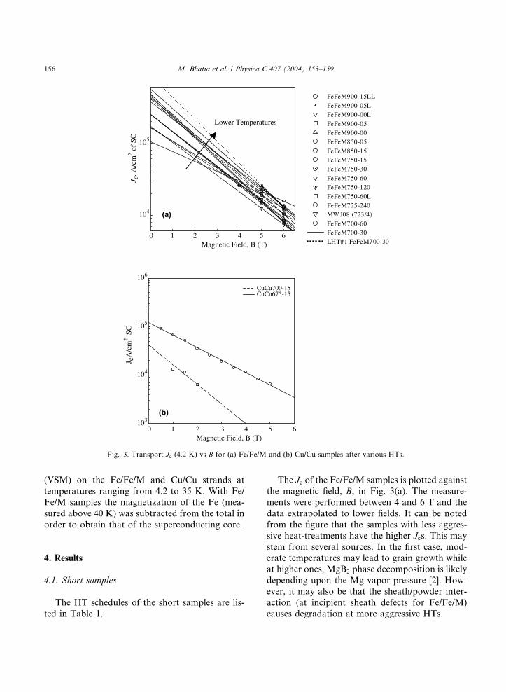
Fig. 3. Transport Jc (4.2 K) vs B for (a) Fe/Fe/M and (b) Cu/Cu samples after various HTs.
156 M. Bhatia et al. / Physica C 407 (2004) 153–159
(VSM) on the Fe/Fe/M and Cu/Cu strands at
temperatures ranging from 4.2 to 35 K. With Fe/
Fe/M samples the magnetization of the Fe (mea-
sured above 40 K) was subtracted from the total in
order to obtain that of the superconducting core.
4. Results
4.1. Short samples
The HT schedules of the short samples are lis-
ted in Table 1.
The Jc of the Fe/Fe/M samples is plotted against
the magnetic field, B, in Fig. 3(a). The measure-
ments were performed between 4 and 6 T and the
data extrapolated to lower fields. It can be noted
from the figure that the samples with less aggres-
sive heat-treatments have the higher Jcs. This maystem from several sources. In the first case, mod-erate temperatures may lead to grain growth while
at higher ones, MgB2 phase decomposition is likely
depending upon the Mg vapor pressure [2]. How-
ever, it may also be that the sheath/powder inter-
action (at incipient sheath defects for Fe/Fe/M)
causes degradation at more aggressive HTs.

M. Bhatia et al. / Physica C 407 (2004) 153–159 157
The less aggressively HTd samples FeFeM700-
30 and FeFeM750-15 samples have 4.2 K Jcs of2.5 · 104 and 2.4 · 104 A/cm2 respectively at an
applied field of 5 T. These values are higher than
those reported by Zhou et al. [3] for their seven-
filament wires and equal to the high Jc values re-ported by Kumakura et al. [4] for their ZrSi2 and
ZrB2 doped MgB2 wires. Our extrapolated trans-
port data are in accordance with the low field
magnetic current density data deduced from the
VSM measurements and depicted in Fig. 4(a) for
the FeFeM700-30 sample. Comparable curves
for the Cu/Cu sample are plotted in Fig. 3(b) and
Fig. 4(b). Fig. 3(b) shows the variation of trans-port Jc with applied field. Here again it can be
seen that the low time–temperature HT, i.e. 675
�C/15 min, is optimal. These data are in accor-
dance with those for bulk MgB2, published else-
where [5].
Fig. 5. BSE of (a) an FeFeM sam
Magnetic Field, B (T)0.5 0.6 0.7 0.8 0.9 1.0 1.1
J c, A
/cm
2 of
SC
104
105
106
4.2K 10K 15K 20K 25K
(a)
Fig. 4. Magnetic Jc vs B for (a) FeFeM
With the Cu/Cu strands, it has been seen that at
higher temperatures the Cu sheath tends to react
with the powder inside, to form unwanted Mg–Cu
phases. The electron back-scattering image (BSE),
Fig. 5(b), shows this reaction layer between the Cu
sheath and the MgB2 powder. Hence, during HTthe Mg–Cu and Mg–B reactions compete. Thus
the optimal time–temperature schedule for Cu/Cu
wire is lower than that of Fe/Fe/M wire, i.e., 675
�C/15 min compared to 700 �C/30 min. For Fe/Fe/M a characteristic problem faced is the formation
of pinholes in the inner Fe layer but this can be
overcome by increasing the thickness of the Fe
sheath.Fig. 6 is a comparison of the FeFeM700-30 and
FeFeM750-15 transport-Jc data with some of the
best published magnetic data [6]. It can be noted
that the transport-Jcs of these samples are com-
parable to the 10% SiC doped bulk samples
ple and (b) a CuCu sample.
Magnetic field, B (T)0.0 0.2 0.4 0.6 0.8 1.0 1.2 1.4 1.6
J c, A
/cm
2 of
SC
102
103
104
105
4.2K10K15K20K25K
(b)
700-30, (b) CuCu675-15 samples.

Magnetic Field, B (T) 0 2 4 6 8
J c A
/cm
2 SC
102
103
104
105
106
FeFeM850-5 FeFeM750-15 FeFeM750-30 FeFeM700-30
Dou (0%SiC) Dou (5%SiC) Dou (10%SiC)
FeFeM700-30 mag
Fig. 6. Jc;m vs B for Fe/Fe/M samples compared to published
data.
Temperature,T(oC)0 10 20 30 40 50
Nor
mal
ized
res
ista
nce
0.0
0.2
0.4
0.6
0.8
1.0
FeFeM700-30FeFeM700-15FeFeM700-05CuCu675-15
Fig. 7. Resistive Tc for Fe/Fe/M and Cu/Cu samples.
Magnetic Field, B (T)0 3 7
J c A
/cm
2 of
SC
103
104
105
106
CuCu675-15 L (Barrel)FeFeM700-30 L (Barrel)CuCu675-15 (Magnetic) FeFeM700-30 (Magnetic) FeFeM700-30 (Short) CuCu675-15 (Short)
Magnetic Field, B (T)0 1 5
J c1/
2 B1/
4
100
1000CuCu675-15LFeFeM700-30L
2 3 4 6 7
1 2 4 5 6
Fig. 8. Jc vs B for FeFeM700-30L and CuCu675-15L (inset:
J 1=2c B1=4 vs B [Kramer plot] for the same samples).
158 M. Bhatia et al. / Physica C 407 (2004) 153–159
reported by Dou et al. [6]. Fig. 7 shows the Tc ofthe optimized Fe/Fe/M and Cu/Cu wires.
Samples with the Fe/Cu barrier/sheath were
also investigated, but found to have low Jcsattributed to significant Fe-barrier breakage and
subsequent poisoning-by-Cu. The cause of the
breakage is thought to stem from the large flow
stress mismatch between the Fe and the Cu. It
should be possible to overcome this problem byusing a thicker Fe sheath. Property data for these
wires is to be reported.
4.2. Long samples
The transport Jcs of 1-m lengths of FeFeM700-
30L and CuCu675-15L were also measured. The Jcmeasurements were performed at 4.2 K in fields of1–6 T. Fig. 8 shows the variation of Jc with appliedfield for these wires. Those long sample Jcs are inaccordance with the transport Jcs measured on the
short (3 cm) samples. However, the reduction of
end-heating effects encountered with barrel
mounting enabled the long samples to be measured
at lower fields (higher transport currents) than was
possible under short-sample mounting. The inset inFig. 8 is the Kramer plot for these Jc values.
5. Conclusions
The optimized heat-treatment for the Fe/Fe/M
MgB2 strand, prepared as described above is 700
�C/30 min while that for Cu/Cu MgB2 strand is675 �C/15 min. Also a 4.2 K, 5 T Jc of 2.5 · 104 A/cm2 has been achieved for the double Fe/monel

M. Bhatia et al. / Physica C 407 (2004) 153–159 159
sheathed wire. Long lengths of wire have been
measured and the results are consistent with the
short length results thereby proving the effective-
ness of the fabrication process.
Acknowledgements
This research work was supported by a State of
Ohio Technology Action Fund Grant, U.S. Air
Force SBIR F33615-02-M-2267, and a Missile
Defense Agency SBIR administered by the U.S.
Air Force, contract no. F33615-02-M-2283. The
authors also wish to thank Dr. S.X. Dou, ISEM,University of Wollongong, Australia.
References
[1] L.F. Goodrich, 2002 HEP Conductor Workshop, August 7
2002, unpublished.
[2] Z.-K. Liu, D.G. Schlom, Q. Li, X.X. Xi, Thermodynamics
of the Mg–B system: implications for the deposition of
MgB2 thin films, cond-mat/0103335, 2001.
[3] S. Zhou, A.V. Pan, H. Liu, S. Dou, Physica C 382 (2002)
349.
[4] Y. Ma, H. Kumakura, A. Matsumoto, H. Hatakeyama, K.
Togano, Supercond. Sci. Technol. 16 (2003) 852.
[5] M. Bhatia, M.D. Sumption, M. Tomsic, E.W. Collings,
Influence of heat treatment schedules on magnetic Jc andphase formation in bulk superconducting MgB2, Physica C,
submitted for publication.
[6] S.X. Dou, S. Soltanian, J. Horvat, X.L. Wang, S.H. Zhou,
M. Ionescu, H.K. Liu, P. Munroe, M. Tomsic, Appl. Phys.
Lett. 81 (18) (2002) 3419.


![Comparative study of cryogenic NbTi/Cu and MgB2/Brass ... · assess the operational cost of CLs References [1] Yukikazu Iwasa: Case Studies in Superconducting Magnets Design and Operational](https://img.pdfslide.us/doc/110x75/5ec374cc7ce18f209434375a/comparative-study-of-cryogenic-nbticu-and-mgb2brass-assess-the-operational.jpg)