Embed Size (px)
Citation preview
Journal of Mechanical Science and Technology 23 (2009) 2390~2416 www.springerlink.com/content/1738-494x
DOI 10.1007/s12206-009-0630-y
Journal of Mechanical Science and Technology
Influence of corner radius on the near wake structure of a transversely
oscillating square cylinder† R. Ajith Kumar1, Chang Hyun Sohn2,* and B. H. Lakshmana Gowda3
1Department of Mechanical Engineering, Amrita Vishwa Vidyapeetham (Deemed University), Amritapuri Campus, Kollam District, India
2School of Mechanical Engineering, Kyungpook National University, 1370, Sankyuk-Dong, Buk-Gu, Daegu, 702-701 Korea 3Department of Mechanical Engineering, BTL Institute of Tecnology, Bommasandra, Bangalore India
(Manuscript Received August 18, 2008; Revised March 25, 2009; Accepted May 19, 2009)
--------------------------------------------------------------------------------------------------------------------------------------------------------------------------------------------------------------------------------------------------------
Abstract The near wake flow field features of transversely oscillating square section cylinders with different corner radii were
studied in an attempt to assess the influence of corner radius. The investigation was performed by using particle image velocimetry (PIV) technique in a water channel with a turbulence intensity of 6.5%. Five models were studied with r/B=0, 0.1, 0.2, 0.3 and 0.5 (r is the corner radius and B is the characteristic dimension of the body), and the body oscil-lation was limited to lock-in condition (at fe/fo=1.0; fe is the excitation frequency and fo is the vortex shedding fre-quency from a stationary cylinder at the same Re). The corner radius was found to significantly influence the flow features around the bodies. Except for r/B=0.5, for all the other cases of r/B ratios, cycle-to cycle variation in the mode of vortex shedding was observed in the case of oscillating cylinders inducing highly non-linear wake characteristics. Apart from variation in the shedding mode, changes in shedding cycle timing were also observed for sharp and rounded square cylinders. The hgher the r/B ratio, shedding in the near wake was found to be more uniform (lesser variation in shedding cycle timings). Another admissible shedding mechanism is newly identified to operate in the near wake of oscillating cylinders now being called as the ‘passive shedding’ mechanism. Results indicate that increasing the corner radius suppresses the possible instabilities of the cylinder.
Keywords: Flow-induced vibration; PIV; Oscillating square cylinder; Wake structure; Corner radius --------------------------------------------------------------------------------------------------------------------------------------------------------------------------------------------------------------------------------------------------------
1. Introduction
When a flexibly mounted bluff cylinder is exposed to a fluid flow, it could be subjected to flow-induced vibrations. Among the various bluff sections, circular, square and rectangular bodies have received more research attention due to their wide application possi-bilities. Compared to a circular cylinder, prismatic bodies (non-circular) such as square and rectangular sections could pose additional aerodynamic chal-lenges such as the galloping phenomenon [1, 2]). Also, these sections (square and rectangular) are suc-
cessfully employed in a variety of practical situations such as in bridges, buildings and also in marine appli-cations. Hence, it is relevant to study and understand their aerodynamic characteristics from a practical point of view. Again, from the practical point of view, the study bears particular importance in the context of a high turbulence environment because in most of the marine engineering and wind engineering applica-tions (where square sections are employed), the in-coming flow is turbulent and it considerably influ-ences the wind load characteristics of buildings and structures [3]. Therefore, understanding the underly-ing flow physics in such a realistic environment is necessary in order to devise means to curb these vi-brations to ensure safety to the potentially prone structures.
†This paper was recommended for publication in revised form byAssociate Editor Kyung-Soo Yang
*Corresponding author. Tel.: +82 53 950 5570, Fax.: +82 53 950 6550 E-mail address: [email protected] © KSME & Springer 2009

R. Ajith Kumar et al. / Journal of Mechanical Science and Technology 23 (2009) 2390~2416 2391
Naudascher et al [4] have conducted studies on the instability of square prisms which are sectionally modified (including corner modifications), particu-larly with respect to galloping oscillations. These researchers concluded that, by introducing appropri-ate sectional modifications, the flow past the prism could be altered so that the lateral exciting forces could be reduced. Bokaian and Geoola [5] have stud-ied the influence of corner radius on the aerodynamic characteristics of a square cylinder which was mounted flexibly in water and with oscillations re-stricted to occur in the transverse direction. They found that both the response amplitude and the oscil-lation frequency of vortex resonance and galloping are highly sensitive to the corner radius of the cylin-der. Kwok et al. [6] studied the effect of edge modifi-cation of rectangular cylinders and have found that corner modification brings down the along-wind and cross-wind responses. Kawai [7] also has investigated the effects of corner modifications (such as corner cut, recession and rounding) on the aero-elastic instabili-ties of square (and rectangular) prisms placed in a turbulent boundary layer. He concluded that corner rounding is the best option to provide aerodynamic stability to prisms. Tamura et al. [8] have numerically studied the influence of corner shape on the aerody-namic characteristics of a square section cylinder and have demonstrated that corner geometry significantly alters the aerodynamic forces acting on the cylinder. Particularly, the drag and lift forces are found to de-crease in order for the sharp square cylinder, the chamfered cylinder and the rounded cylinder, respec-tively. Further to this, Tamura and Miyagi [9], by conducting experimental studies, have found that chamfered and rounded corners decrease the wake width and thereby the drag forces acting on a square section cylinder. They further concluded that corner modification promotes reattachment of the separated shear layers. Dalton and Zheng [10] present the re-sults of numerical studies on square and diamond sections, with and without corner rounding at Rey-nolds numbers of 250 and 1000. The investigators have found that corner rounding has resulted in con-siderable reduction of the drag and lift values. Re-cently, Hu et al. [11] have investigated the effects of corner radius on the near wake of a stationary square prism at Reynolds number values of 2600 and 6000, at low free stream turbulence intensity condition. They found that corner radius significantly influences the wake characteristics such as vorticity shed, Strou-
hal number and vortex formation length amongst other parameters. Similar studies on the influence of corner modifications have also been performed by Delany and Sorensen [12], Bearman et al. 13] and Zheng and Dalton [14]. All these studies were mainly focused on the effects on corner radii on the aerody-namic characteristics such the Strouhal number, vor-ticity shed and, the lift and drag forces acting on a stationary cylinder. It was found that the flow field features around an oscillating square cylinder are not yet considered for a detailed analysis, particularly with respect to the influence of corner radius. It is to be emphasized that for some selected bluff bodies (sharp square, circular and triangular sections), Ongoren and Rockwell [15] have provided some fundamental insights into the near wake dynamics, but their discussion is restricted only to some specific amplitude positions of the oscillating body and not over a complete cycle of body oscillation. On the other hand, Luo [16] has discussed the flow field features around an oscillating sharp square cylinder (zero corner radius) over a complete cycle of oscilla-tion and reports various modes of vortex shedding observed at different reduced velocity conditions. But, here again, how the corner modification influences the near wake flow region of the cylinder is not ad-dressed. The present paper is an attempt to comple-ment previous research studies in the literature by bringing to light the influence of corner radius on the flow field around an oscillating square section in a high turbulence environment. In oscillating conditions, a detailed flow analysis (qualitative) is attempted over a complete cycle of oscillation, particularly emphasiz-ing the mode and mechanism of vortex shedding.
In this paper, utilizing particle image velocimetry, the near wake of a square cylinder with different cor-ner radii is studied as it undergoes a complete oscilla-tory cycle at lock-in condition, i.e., fe/fo=1.0 (where fe is the excitation frequency and fo is the Strouhal frequency for the stationary cylinder at the same Rey-nolds number). The main objective of this study is to assess the influence of corner radius on the near wake characteristics of the square cylinder.
2. Experimental set-up and instrumentation
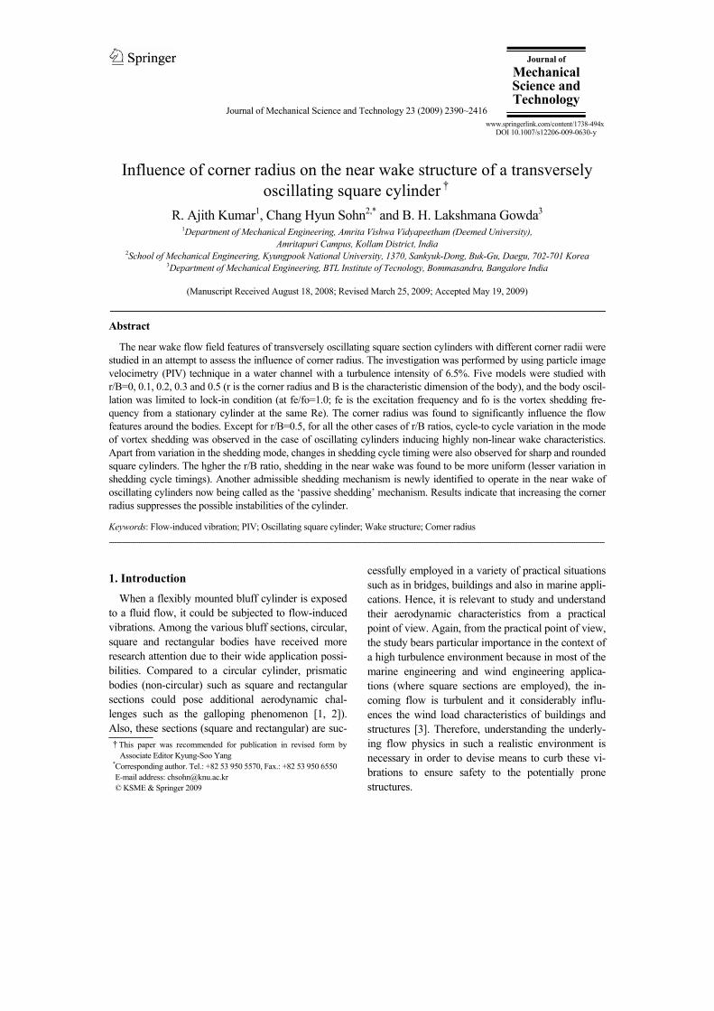
All the experiments were performed in a flow visualization facility, which is basically a water chan-nel (Fig. 1) that consists of a tank 2.5 m x 1.5 m with a depth of 0.3 m, made out of acrylic sheets (to pro-
2392 R. Ajith Kumar et al. / Journal of Mechanical Science and Technology 23 (2009) 2390~2416
vide transparency). The tank is filled with water to a depth of 135 mm, and at one end of the tank are lo-cated two sets of aluminum discs (vanes) with suit-able spacing between them. The vanes, when rotated, act as paddles and create the flow in the test section. A variable speed D.C. motor with suitable gear ar-rangement is used for rotating the vanes and a fairly wide range of flow speeds could be achieved in the test section. The flow is guided into the test section (420 mm width; Fig. 1) by means of suitably de-signed guide blocks. By varying the speed of rotation, the velocity in the test section can be varied up to 0.2 m/s without any wavy oscillations in the flow. The square models used for the study are of size 30mm x 30mm cross section and made of acrylic. Five models were used for experimentation with corner radius ratios (r/B; r is the corner radius and B is the charac-teristic dimension of the body, i.e., 30mm) of 0, 0.1, 0.2, 0.3 and 0.5 with a total model height of 346mm. Also, the models have been provided with a smooth surface finish with their side faces made straight and leveled.
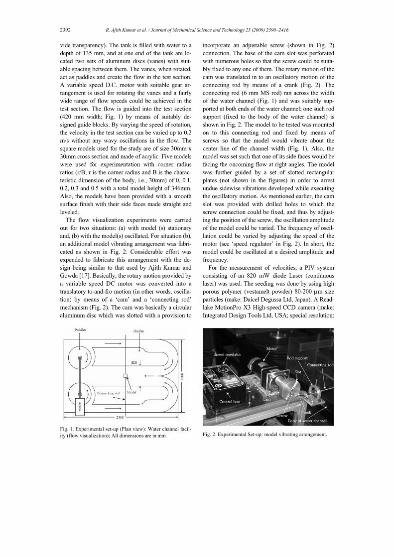
The flow visualization experiments were carried out for two situations: (a) with model (s) stationary and, (b) with the model(s) oscillated. For situation (b), an additional model vibrating arrangement was fabri-cated as shown in Fig. 2. Considerable effort was expended to fabricate this arrangement with the de-sign being similar to that used by Ajith Kumar and Gowda [17]. Basically, the rotary motion provided by a variable speed DC motor was converted into a translatory to-and-fro motion (in other words, oscilla-tion) by means of a ‘cam’ and a ‘connecting rod’ mechanism (Fig. 2). The cam was basically a circular aluminum disc which was slotted with a provision to
Fig. 1. Experimental set-up (Plan view): Water channel facil-ity (flow visualization); All dimensions are in mm.
incorporate an adjustable screw (shown in Fig. 2) connection. The base of the cam slot was perforated with numerous holes so that the screw could be suita-bly fixed to any one of them. The rotary motion of the cam was translated in to an oscillatory motion of the connecting rod by means of a crank (Fig. 2). The connecting rod (6 mm MS rod) ran across the width of the water channel (Fig. 1) and was suitably sup-ported at both ends of the water channel; one such rod support (fixed to the body of the water channel) is shown in Fig. 2. The model to be tested was mounted on to this connecting rod and fixed by means of screws so that the model would vibrate about the center line of the channel width (Fig. 1). Also, the model was set such that one of its side faces would be facing the oncoming flow at right angles. The model was further guided by a set of slotted rectangular plates (not shown in the figures) in order to arrest undue sidewise vibrations developed while executing the oscillatory motion. As mentioned earlier, the cam slot was provided with drilled holes to which the screw connection could be fixed, and thus by adjust-ing the position of the screw, the oscillation amplitude of the model could be varied. The frequency of oscil-lation could be varied by adjusting the speed of the motor (see ‘speed regulator’ in Fig. 2). In short, the model could be oscillated at a desired amplitude and frequency.
For the measurement of velocities, a PIV system consisting of an 820 mW diode Laser (continuous laser) was used. The seeding was done by using high porous polymer (vestamelt powder) 80-200 µm size particles (make: Daicel Degussa Ltd, Japan). A Read-lake MotionPro X3 High-speed CCD camera (make: Integrated Design Tools Ltd, USA; special resolution:
Fig. 2. Experimental Set-up: model vibrating arrangement.

R. Ajith Kumar et al. / Journal of Mechanical Science and Technology 23 (2009) 2390~2416 2393
Fig. 3. Experimental set-up: PIV system with CCD camera.
1280 pixels x 1024 pixels) was used to record the flow details and the particle images were processed by using pro-VISION software package. The interro-gation area was 32 pixels x 32 pixels. A photograph of the test set up with the PIV system is shown in Fig. 3. The laser sheet was made to pass through the model at a height of 75mm from the base of the water channel. The CCD camera was located below the tank to capture the images (Fig. 3), normal to the deflected laser beam. For computation of velocity, the images were captured at 300 fps (frames per sec) and for qualitative analysis (flow visualization), a frame rate of 8 (fps) was adopted.
All the results presented are at a Reynolds number of 5200 referred to the side dimension of the square cylinder (B=30 mm). The turbulence intensity of the incident flow was 6.5%. The natural vortex shedding frequency (fo) from the stationary square cylinder at Re=5200 is calculated (using PIV pro-VISION soft-ware) at a spatial location with X/B=2.0 and Y/B=1.5 (horizontal distance X and vertical distance Y are measured from the center of the cylinder) and for all investigations with body oscillation, fe/fo is set at a value of 1.0 (where fe is the excitation frequency provided to the model (s)). The peak-to-peak ampli-tude adopted for forced oscillation studies is 0.32B for all the cases. As mentioned earlier, five cylinders with different corner radii were investigated in this experimental program. Fig. 4 is a definition sketch showing the typical geometry of a rounded square section cylinder tested.
The flow velocity and the turbulence intensity was closely uniform over 70% of the width of the test section, the variation being less than 2%.
Fig. 4. Definition sketch showing the typical cylinder geome-try; r/B=0, 0.1, 0.2, 0.3 and 0.5. Physical quantities are com-puted at P (2B, 1.5B).
3. Results and discussion
3.1 Mode and mechanism of vortex shedding, and the associated aerodynamic characteristics: in-fluence of r/B ratio (qualitative analysis)
In this section, the flow field features, particularly the mode and mechanism of vortex shedding pertain-ing to cylinders at all the five r/B ratios, viz., r/B = 0,0.1,0.2,0.3 and 0.5 considered for investigation are presented and discussed with a view to deduce the influence of corner radius. Additionally, the possibili-ties of cylinder excitation with respect to lift and drag forces are also discussed with reference to the corner radius ratio (r/B). In all the cases of study, the oscilla-tion frequency (fe) was set equal to the Strouhal fre-quency of the stationary cylinder (fo), i.e., fe/fo=1.0 at a Reynolds number value of 5200 (with reference to B). Also, as mentioned earlier, the peak-to-peak amplitude value adopted was 32% of the side dimen-sion of the square cylinder(s) in all the cases.
Quite interestingly, in almost all the cases (except for the case with r/B=0.5, that is for circular cylinder), it was found that the mode of vortex shedding need not be the same in all the oscillatory cycles of the cylinder(s), and hence, two predominant modes (ob-served in two cycles) are presented for each case (ex-cept for the circular cylinder). However, for a sharp square cylinder, a notable deviation was observed in a third mode, indicating unique vortex-vortex interac-tion and is separately presented and discussed. For all other rounded square cylinders, only two predominant shedding modes were observed. Other modes of shedding observed were found to be somewhat close to one of these predominant modes and hence, these shedding modes (with minor deviations) are not pre-sented here. Only the salient stages of shedding are presented. In all the flow visualization photographs

2394 R. Ajith Kumar et al. / Journal of Mechanical Science and Technology 23 (2009) 2390~2416
presented, the corresponding time instant (t/T) is shown at the top left corner; t is the time (in sec) and T is the oscillatory period (in sec). In all the photo-graphs, the flow is taking place from left to right as viewed.
3.1.1 Mode and mechanism of shedding at r/B=0 Fig. 5 shows the vortex shedding sequence from
the sharp square cylinder (r/B=0) in a typical oscilla-tory cycle (C1). As the cylinder advances its motion during the first half of the oscillatory cycle C1 (from TDC to BDC), at TDC, the top shear layer is found to generate a nascent vortex V2 just behind the leading edge. Also, simultaneously, the inwardly curved top shear layer develops another vortex V1 close to the trailing edge. Following the morphology of vortex
shedding suggested by earlier investigators (e.g., Deniz and Staubli [18]), vortex V1 could be identified as an impinging leading edge vortex (hence desig-nated as ILEV1). Following Komatsu and Kobayashi [19], the vortex V2 generated just behind the leading edge in response to the transverse motion of the cyl-inder could be identified as motion-induced vortex (hence, designated as MIV2). Hereafter, vortices of similar formation patterns are accordingly designated. ILEV1 grows with time and when the cylinder reaches BDC, the vortex (MIV2) is found to coalesce with the vortex ILEV1 forming a large scale vortex V12. At BDC, this large scale vortex (V12) begins shedding due to the momentary re-attachment of the top shear layer on to the corresponding side surface of the cylinder. Also, at BDC, another new vortex
(a) (b) (c)
(d) (e) (f)
(g) (h) (i)
(j) (k)
Fig. 5. Vortex shedding sequence over an oscillatory cycle (C1); r/B=0.
R. Ajith Kumar et al. / Journal of Mechanical Science and Technology 23 (2009) 2390~2416 2395
(ILEV4) starts nucleating on the bottom shear layer. In the second half of the cylinder oscillatory motion
(from BDC to TDC again), the top shear layer con-tributes another new vortex MIV5 formed immedi-ately after BDC (seems to be apparently weak). Vor-tex ILEV4 registers a continuous growth achieving significant size as the cylinder reaches TDC again. Meanwhile, vortex V12 moves further downstream, and the weakly formed vortex MIV5, after attaining its maximum size, gets shed at TDC. Compared to ILEV4, MIV5 attains only a limited size at the time of shedding. Interestingly, near the mid-way of the reverse journey (from BDC to TDC), a small scale vortex MIV6 is generated on the bottom shear layer (at t=9/12T), which seems to closely interact with the large scale vortex ILEV4 but not coalesce with it. The growth and forward convective motion of MIV6 is found to be severely hampered by the existence of ILEV4, making the small scale vortex (MIV6) slow and ‘dwarf’.
As seen in Fig. 5, during one cycle of cylinder os-cillatory motion, the flow field offers the possibility of vortex-vortex interactions, sometimes leading to their coalescence and sometimes, not. In closely ob-serving the process of coalescence, it could be inter-preted as the ‘absorption’ of small scale vorticity by the larger ones. This absorption, if complete, would lead to coalescence (as observed in the case of ILEV1 and MIV2) and if incomplete, would lead to a kind of ‘dwarfing’ or ‘premature’ shedding of small scale vortices (as in the case of MIV6). This seems to de-pend on the relative position of the interacting vor-tices as well as on their relative strengths.
To understand the pattern of shedding cycles, in-stantaneous velocities (U) are computed (for 20 sec-onds) at a spatial location with X=2B and Y=1.5B; both X and Y are measured from the cylinder center. The result (U versus t; t is the time) is plotted as shown in Fig. 6 (U-t plot). From the time history of instantaneous velocity fluctuations, it could be seen (Fig. 6) that the shedding time intervals are not equal. On careful observation, amidst major shedding cycles (represented by larger peaks of velocity fluctuations), shorter peaks also could be seen at t = 4.64 sec, 12.09987 sec (more clear), 13.1885 sec, 14.8651 sec, 16.29 sec (more clear) and 19.168 sec respectively. Hence, it was strongly suspected that, this might be possibly due to cycle-to-cycle changes in the vortex shedding mode. On analyzing another oscillatory cycle (C2), this was found to be quite true, confirming
Fig. 6. Instantaneous velocity fluctuations with respect to time; r/B=0 (oscillating cylinder).
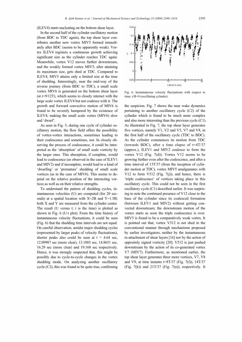
the suspicion. Fig. 7 shows the near wake dynamics pertaining to another oscillatory cycle (C2) of the cylinder which is found to be much more complex and also more interesting than the previous cycle (C1). As illustrated in Fig. 7, the top shear layer generates five vortices, namely V1, V2 and V5, V7 and V8, in the first half of the oscillatory cycle (TDC to BDC). As the cylinder commences its motion from TDC (towards BDC), after a time elapse of t=4T/37 (approx.), ILEV1 and MIV2 coalesce to form the vortex V12 (Fig. 7(d)). Vortex V12 seems to be growing further even after the coalescence, and after a time interval of 13T/37 (from the inception of cylin-der motion at TDC), vortex MIV5 amalgamates with V12 to form V512 (Fig. 7(j)), and hence, there is ‘triple coalescence’ of vortices taking place in this oscillatory cycle. This could not be seen in the first oscillatory cycle (C1) described earlier. It was surpris-ing to note the continued presence of V12 close to the base of the cylinder since its coalesced formation (between ILEV1 and MIV2) without getting con-vected downstream; the downstream motion of the vortex starts as soon the triple coalescence is over. MIV5 is found to be a comparatively weak vortex. It is pointed out that, vortex V512 is not shed in the conventional manner through mechanisms proposed by earlier investigators, neither by the instantaneous re-attachment of shear layers [16] nor by the action of oppositely signed vorticity [20]. V512 is just pushed downstream by the action of its co-generated vortex V7 (MIV7). Furthermore, as mentioned earlier, the top shear layer generates three more vortices, V7, V8 and V9, at time instants t=8T/37 (Fig. 7(f)), 14T/37 (Fig. 7(k)) and 21T/37 (Fig. 7(n)), respectively. It
2396 R. Ajith Kumar et al. / Journal of Mechanical Science and Technology 23 (2009) 2390~2416
(a) (b) (c)
(d) (e) (f)
(g) (h) (i)
(j) (k) (l)
(m) (n) (o)
(p) (q) (r)
(s) (t) (u) Fig. 7. Vortex shedding sequence over another oscillatory cycle (C2); r/B=0.

R. Ajith Kumar et al. / Journal of Mechanical Science and Technology 23 (2009) 2390~2416 2397
may be noted that the vortices MIV7 and MIV8 ap-peared to be very weak and were difficult to detect in the flow field. But, by careful observation in repeated trials, their presence is confirmed as shown. These vortices are shed in a manner quite similar to V512; V7 is shed by the action of V8, and V8 in turn is shed by the action of V9 (MIV9). However, V9 gets shed by the momentary re-attachment of the feeding shear layer on to its corresponding side surface. Thus, the top shear layer sheds four vortices (including the coa-lesced vortex V512) in this oscillatory cycle (C2) as against two vortices in the previous cycle (C1). The lower shear layer is also found to exhibit the phe-nomenon of ‘triple coalescence’ as observed for the upper shear layer. The vortex ILEV6 formed at an instant of t=11T/37 (Fig. 7(h)) coalesce with the vortex MIV10 (formed at t=24T/37) to form V106 (at t=31T/37; Fig. 7(r)). At the instant t=33T/37, the rear bottom corner witnesses the formation of another new vortex V11 (ILEV11). Similar to vortex V12, in this case, V6 also registers growth for a considerable pe-riod of time staying quite close to the cylinder base. At TDC, the coagulated vortex V106 is pushed down-stream and thus shed by the growth of V11 at the rear corner similar to V512. V11 is found to be very weak and short-lived, and it was very difficult to identify its presence in the flow field. Besides V106, the lower shear layer also sheds another vortex MIV3 (formed at t=0, i.e., at TDC and shed at t=7T/37), contributing a total of two vortices per oscillatory cycle as in the previous oscillatory cycle (C1). Vortex V13 is gener-ated at an instant t=31T/37 and V14 begins to form at TDC. In both the cycles considered (C1 & C2), the near-wake is found to undergo a base swing about the wake centerline; Fig. 5(j) indicates an upward swing and Fig. 7(e) indicates a downward swing.
From close observation, it could be inferred that vortex-vortex interactions and the possible coales-cence significantly alter the convection velocity of the vortices downstream of the body, which in turn modi-fies the shedding frequency. For example, in cycle C2, even after formation, the vortex V7 was found to be nearly stagnant for a considerable period of time on the top side surface. This is possibly due to the proc-ess of coalescence between V5 and V12 (forming V512). From cycle analysis, it is also understood that there could be vortex-vortex interactions between dissimilar vortices (with opposite vorticities) one belonging to the upper shear layer and the other be-longing to the lower shear layer. From another oscil-
latory cycle (C3), such an instant is depicted in Fig. 8 wherein the vortex (seen diffused) emerging from the top shear layer (V1) interacts with the bottom vortex (V2). The timing sequences are also shown at the top left hand side corner of the photographs; all these instances are taken when the cylinder is approaching TDC in the second half of the oscillatory cycle. It can be seen that the top vortex (V1) moves increasingly closer to the bottom one (V2) as the cylinder moves up (towards TDC in its reverse journey) and interacts with it. This vehement interaction process is high-lighted in the sketch provided by the side of Fig. 8(d). Besides weakening (through vorticity annihilation), this interaction seems to have substantially reduced the forward convection velocity of the top vortex V1. Hence, the reason for the variation in the shedding cycle time (shown in Fig. 6) could be primarily at-tributed to the changes in the mode of vortex shed-ding occurring in the near wake flow field of the body significantly influenced by the nature of vortex-vortex interactions as described above.
(a)
(b)
(c)
(d) Fig. 8. Some instances from an oscillatory cycle C3 showing unique vortex-vortex interaction; r/B=0.

2398 R. Ajith Kumar et al. / Journal of Mechanical Science and Technology 23 (2009) 2390~2416
As outlined earlier, Fig. 6 shows both the major and minor vortex shedding cycles; major shedding cycles are characterized by higher peak of velocity fluctuations and the minor shedding cycles are repre-sented by the lower peaks. From the number of major shedding cycles (Fig. 6), the average shedding fre-quency was calculated to be 0.7096 Hz (fN) from which the Strouhal number (S= fN.B/Uo; Uo is the free stream velocity) was calculated to be 0.125. For the stationary cylinder also, a U-t plot was obtained (but not presented here) at the same spatial location (2B, 1.5B) and at the same Reynolds number (=5200), which gave a shedding frequency value of 0.697Hz from which the Strouhal number was calculated to be 0.123. For other r/B ratios also, the Strouhal number was computed for stationary cylinders and presented in the ensuing sections. But the U-t plots are not pre-
sented instead, only the values are given. 3.1.2 Mode and mechanism of shedding at r/B=
0.1 The mode of vortex shedding from the rounded
square cylinder with r/B=0.1 is shown in Fig. 9. As the cylinder moves from TDC to BDC (oscillatory cycle C1), at TDC, the top shear layer give rise to two vortices: vortex ILEV1 at the top rear corner of the cylinder and MIV3 close to the upper leading edge of the cylinder (Fig. 9(a)). In the meanwhile, at TDC, the bottom shear layer also contributes a new vortex MIV2 which also starts to grow after inception. When the cylinder reaches BDC, the top shear layer gener-ates one more vortex MIV5 which further grows and moves downstream, and finally sheds at an instant t=17T/20 (Fig. 9(k)). Quite interestingly, immediately
(a) (b) (c)
(d) (e) (f)
(g) (h) (i)
(j) (k) (l)
Fig. 9. Vortex shedding sequence over an oscillatory cycle (C1); r/B=0.1.

R. Ajith Kumar et al. / Journal of Mechanical Science and Technology 23 (2009) 2390~2416 2399
after BDC, vortices V3 and V1 coalesce to form a larger vortex V31 which gets shed soon after the for-mation, due to the momentary reattachment of the feeding shear layer onto the top side surface. The small scale vortex V2 is found to get shed at a time instant t=6T/20 (Fig. 9(d)).
In the reverse journey of the cylinder (from BDC to TDC again), just after BDC (at t=11T/20), the bottom shear layer curls up to form another nascent vortex ILEV4 at the bottom rear corner. During the rest of the oscillatory cycle, V4 continuously grows to achieve a significant size and, at near TDC, it gets shed downstream (Fig. 9(k); t = 17T/20). At this stage, the wake appears to have a swing upwards about the axis of the cylinder making an angle. Interestingly, compared to V4, the growth of V5 is much restricted. This is possibly due to the presence of other co-shedding vortices, V1 and V3 till BDC and thereafter by V31. More specifically, this could be due to higher absorption of fed vorticity by the stronger vortices (V3 and V1). V5 is found to get shed by instantane-ous re-attachment of the feeding shear layer on to the top side surface. At an intermediate amplitude posi-tion of the cylinder (t=15T/20; Fig. 9(i)), MIV6 nu-cleates on the bottom shear layer. At TDC, two new vortices (V7 and V8) are observed to form on the top shear layer. In this oscillatory cycle (C1), the top shear layer sheds exactly two vortices per cycle of oscillation while the bottom shear layer contributes three vortices.
It is very evident that vortex–vortex interaction and consequent coalescence occurs in the top shear layer, but not in the bottom one. It is particularly noticed that vortex V1 remains in the flow field for a rela-tively long period of time, enabling vortex V3 to in-teract with it leading to an amalgamation.
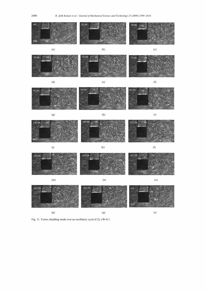
From the time history of velocity fluctuations (U-t plot) computed at X/B=2.0, Y/B=1.5 (Fig. 10), it could be seen that significant variation occurs in the vortex shedding cycle timing; the shedding cycle could be as short as 0.4775 seconds (corresponds to minor shedding cycle with lower peak of velocity fluctuation) or as long as nearly 1.40 seconds (corre-sponds to major shedding cycle with larger peak of velocity fluctuation). Similar to the case with r/B=0, there could be changes in the shedding sequence in this case also as shown in Fig. 11 for another oscilla-tory cycle (C2). Unlike the previous cycle (C1) where vortex coalescence occurs (forming V31 on the top shear layer) after BDC (Fig. 9(g)), it happens here
before BDC (t=10T/26; Fig. 11(i)). Another aspect which makes the near wake dynamics interesting (in C2) is the strong interaction between vortices MIV5 and ILEV6, as shown in Fig. 11. As vortex V5 (formed on the top shear layer; Fig. 11(h)) moves downstream sliding along the top side surface, vortex V6 (which is formed on the bottom rear corner of the cylinder) rolls up along the rear side surface (cylinder base) and a strong interaction takes place between them at instances t=19T/26 to 25T/26 (Figs. 11(n)-(q)). This close interaction might possibly have sub-stantially reduced the convection velocity of these vortices downstream. Surprisingly, even after vehe-ment interaction for a considerable period of time, both these vortices (V5 and V6) seem to mark their stable presence in the flow field. Such an intense in-teraction was not observed in cycle C1. After the shedding of V5 (Fig. 11(p); t=24T/26), ILEV6 begins to coalesce with another bottom vortex MIV7 (formed close to the bottom leading edge of the cyl-inder) to form V67 at TDC (Fig. 11(r)). In this cycle (C2), besides V6, the bottom shear layer also sheds minor vortices V2 and V4. Hence, similar to the pre-vious cycle (C1), the shedding contributions of the shear layers are not equal; the top shear layer sheds two vortices while the bottom shear layer sheds three vortices. Similar to the sharp cylinder case, a base swing has been observed in this case also, but with a reduced swing angle (see Figs. 9 (f) & (k)).
From the U-t plot (Fig. 10), considering the major shedding cycles, the average frequency of shedding is calculated to be 0.762. which gives a Strouhal number value of 0.134 (close to the stationary cylinder’s value of 0.132).
Fig. 10. Instantaneous velocity fluctuations with respect to time; r/B=0.1 (oscillating cylinder).
2400 R. Ajith Kumar et al. / Journal of Mechanical Science and Technology 23 (2009) 2390~2416
(a) (b) (c)
(d) (e) (f)
(g) (h) (i)
(j) (k) (l)
(m) (n) (o)
(p) (q) (r) Fig. 11. Vortex shedding mode over an oscillatory cycle (C2); r/B=0.1.

R. Ajith Kumar et al. / Journal of Mechanical Science and Technology 23 (2009) 2390~2416 2401
3.1.3 Mode and mechanism of shedding at r/B= 0.2
The shedding sequence pertaining to the rounded square cylinder with r/B=0.2 is given in Fig. 12. As can be seen, as the cylinder traverses from TDC to BDC (first half of the oscillatory cycle C1), the top shear layer begins to curl forming vortex V1 (ILEV1) at the rear corner of the cylinder which registers a continuous growth with time. Soon after TDC, an-other vortex MIV4 (appears very weak) is also gener-ated on the top shear layer, close to the top leading edge (Fig. 12(b); t=2T/18). When the cylinder ap-proaches BDC (just before BDC), V1 and V4 starts to coalesce and form the large scale vortex V14 at BDC. Also, at BDC, V14 is found to get shed (Fig. 12(f)). The bigger vortex V1 appears to hinder the growth of
V4 by absorbing a certain amount of vorticity and causes it to have a premature dissolution with V1. Just before BDC, a new vortex ILEV2 can be seen nucleating on the bottom shear layer at the bottom rear corner of the cylinder (Fig. 12(e)). Also at BDC, the formation of two more vortices takes place: vortex MIV3 on the top shear layer and vortex MIV5 on the bottom shear layer (Fig. 12(f)).
All the new vortices V2, V3 and V5, grow with time. It was difficult to identify, observe and analyze the presence and motion of V3 and V5, since they appeared very weak in the flow field. All through the growth of V5 and V2, the bottom shear layer is found to be nearly re-attached to the bottom rear corner of the cylinder. As the cylinder again approaches TDC, V3 moves downstream and get shed before TDC (Fig.
(a) (b) (c)
(d) (e) (f)
(g) (h) (i)
(j) (k) (l) Fig. 12. Mode of vortex shedding over an oscillatory cycle (C1); r/B=0.2.

2402 R. Ajith Kumar et al. / Journal of Mechanical Science and Technology 23 (2009) 2390~2416
12(j); t=16T/18). Meanwhile, at TDC, V5 is also get-ting shed, collapsing the separation bubble under the bottom shear layer (Fig. 12(l)). Another salient aspect noted is the swing of the wake (wake axis making an angle with the cylinder axis) as the cylinder ap-proaches TDC; the wake swing appears to start at t=16T/18 (Fig. 12(j)) and continues till TDC. Throughout the various stages of this oscillatory cycle, both shear layers remain nearly attached to their cor-responding sides, exhibiting negligible divergence (with respect to their corresponding sides).
It may be noted that vortex V2 is shed from the body by the pushing action of V5 at the bottom rear corner of the body in a similar manner to that of V106 and V512 for r/B=0 (Fig. 7). From the flow field analysis, it is very clear no action of oppositely signed vorticity is working on V2. Moreover, the formation and growth of V2 itself occurs with its feeding shear layer occupying a very close configuration (nearly touching) with the bottom side surface, and therefore, the shedding process cannot be due to the momentary re-attachment of the feeding shear layer. In the cases of V106 and V512 (Fig. 7; r/B=0) also, as mentioned earlier, the absence of other shedding mechanisms was clearly seen. Hence, this could be considered as the third means by which a vortex could be shed from a bluff body, now being referred to as ‘passive vortex shedding’ wherein the vorticity supply to the vortex through its feeding shear layer is not actually cut. Based on the present results, the process of vortex shedding is now being classified as ‘active vortex shedding’ wherein the vorticity supply to the vortex is cut through conventional mechanisms proposed ear-lier (Gerrard [20], Luo [16]) and ‘passive vortex shedding’ (proposed now) wherein the vorticity sup-ply to the vortex is not actually cut; instead the grown vortex is merely pushed downstream by the action of another growing vortex (co-shedding vortex) contrib-uted by the same feeding shear layer. A sketch illus-trating the proposed passive shedding mechanism is further shown in Fig. 13 for better clarity.
In this cycle, each shear layer sheds exactly two vortices per cycle of oscillation. However, when the U-velocity fluctuations are computed and plotted with respect to time (Fig. 14), the shedding occurs with uneven cycle timings (similar to the previous cases with r/B=0 and 0.1). The cycle timing could be as short as 0.1958 seconds (minor shedding cycle) and could be as long as 1.315 seconds (major shedding cycle). This directly indicates that the vortex shedding
Fig. 13. Proposed ‘passive vortex shedding’ mechanism; vortex V2 is pushed downstream by the co-generated vortex V1.
Fig. 14. Instantaneous velocity fluctuations with respect to time; r/B=0.2 (oscillating cylinder).
is not occurring alike in all the cycles and there could be variations as observed for the smaller r/B ratios.
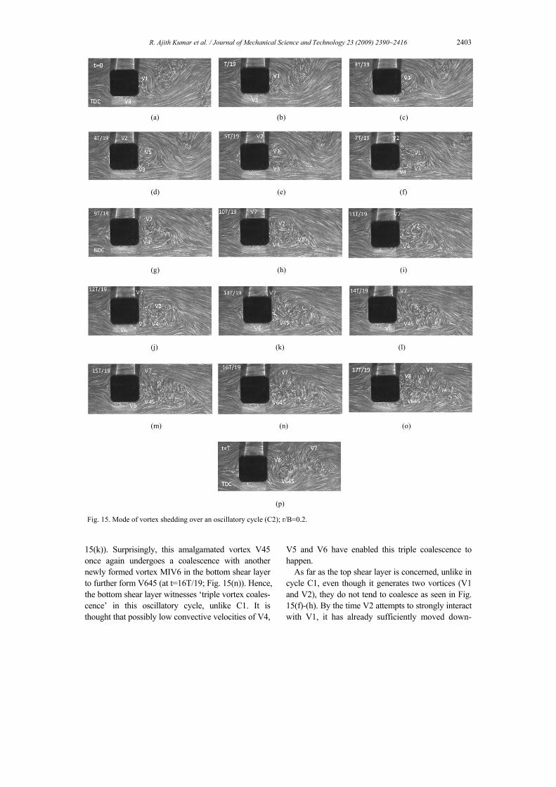
Similar to the previous cases, flow visualization analysis performed on another oscillatory cycle (C2) confirmed this aspect and is presented in Fig. 15. In cycle C1, during the first half of the oscillatory cycle (TDC to BDC), only towards the end (near BDC), the bottom shear layer gives rise to a new vortex, whereas in this cycle (C2), as can be seen (Fig. 15), during the first half of the cycle, two vortices MIV3 (Fig. 15(a)) and ILEV4 (Fig. 15(f)) are generated on the bottom shear layer. Also, during the second half of the cycle (BDC to TDC again), an extremely short-lived and very weak vortex V5 is generated on the bottom shear layer (Fig. 15(j)) which, soon after its formation, amalgamates with V4 to form V45 (at t=13T/19; Fig.
R. Ajith Kumar et al. / Journal of Mechanical Science and Technology 23 (2009) 2390~2416 2403
15(k)). Surprisingly, this amalgamated vortex V45 once again undergoes a coalescence with another newly formed vortex MIV6 in the bottom shear layer to further form V645 (at t=16T/19; Fig. 15(n)). Hence, the bottom shear layer witnesses ‘triple vortex coales-cence’ in this oscillatory cycle, unlike C1. It is thought that possibly low convective velocities of V4,
V5 and V6 have enabled this triple coalescence to happen.
As far as the top shear layer is concerned, unlike in cycle C1, even though it generates two vortices (V1 and V2), they do not tend to coalesce as seen in Fig. 15(f)-(h). By the time V2 attempts to strongly interact with V1, it has already sufficiently moved down-
(a) (b) (c)
(d) (e) (f)
(g) (h) (i)
(j) (k) (l)
(m) (n) (o)
(p) Fig. 15. Mode of vortex shedding over an oscillatory cycle (C2); r/B=0.2.

2404 R. Ajith Kumar et al. / Journal of Mechanical Science and Technology 23 (2009) 2390~2416
stream undergoing considerable diffusion. Similar to V3 in cycle C1, V7 (very weak vortex, similar to V3) originates in cycle C2 just after BDC (Fig. 15(h)) and gets shed well before TDC (Fig. 15(m); t=15T/19). The base swing, even though present, is further re-duced in this case (see Fig. 12(j)).
From Fig. 15, it could also be inferred that the oc-currence of minor shedding cycles is attributable to the shedding of weaker vortices (like V7) and the major shedding cycles (with comparatively larger shedding cycle timings and also with higher peaks of velocity fluctuations) are a consequence of the shed-ding of stronger vortices (like V645). Considering the major shedding cycles, the average frequency of shedding is calculated to be 0.8748, which gives a Strouhal number value of 0.154 (slightly higher than the value for the stationary cylinder’s value of 0.1504).
3.1.4 Mode and mechanism of shedding at r/B=0.3 Mode of vortex shedding at r/B=0.3 is presented in
Fig. 16. During the start of the oscillatory cycle (C1), at TDC, the top shear layer gives rise to vortex ILEV1 at the rear corner of the cylinder. Soon after TDC, the same shear layer generates the vortex MIV2 (Fig. 16(b); t=T/15). Both V1 and V2 grow with time as the cylinder moves towards BDC. At an instant t=6/15T, vortices V1 and V2 coalesce to form a still larger scale vortex V12 (Fig. 16(g)). Then soon after the formation (amalgamation), shedding of V12 oc-curs. In the meanwhile, the bottom shear layer con-tributes two new vortices, V3 and V4. The weak vor-tex ILEV3 forms at the bottom rear corner simultane-ously with V1 at TDC, but it was found to be shed after a shorter interval (t=2/15T; Fig. 16(c)). Immedi-ately after the shedding of V3, ILEV4 nucleates on the bottom shear layer (Fig. 16(d)) at the rear corner, which also was found to be very weak and short-lived (sheds at t=5/15T; Fig. 16(f)). Again, soon after the shedding of V4, just before BDC, the bottom shear layer once again curls at the bottom rear corner to form ILEV5 (Fig. 16(g)). Compared to V3 and V4,
(a) (b) (c)
(d) (e) (f)
(g) (h) (i)
(j) (k) (l) Fig.16. Vortex shedding mode during an oscillatory cycle (C1); r/B=0.3.
R. Ajith Kumar et al. / Journal of Mechanical Science and Technology 23 (2009) 2390~2416 2405
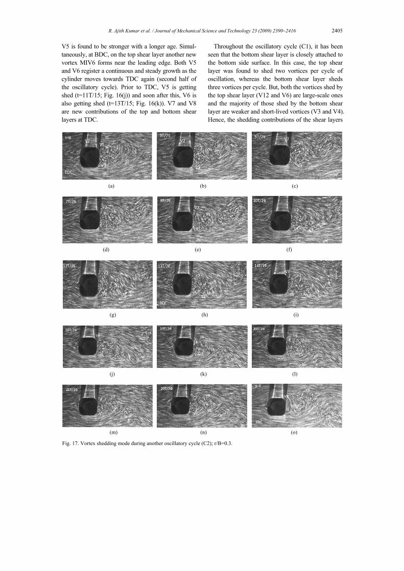
V5 is found to be stronger with a longer age. Simul-taneously, at BDC, on the top shear layer another new vortex MIV6 forms near the leading edge. Both V5 and V6 register a continuous and steady growth as the cylinder moves towards TDC again (second half of the oscillatory cycle). Prior to TDC, V5 is getting shed (t=11T/15; Fig. 16(j)) and soon after this, V6 is also getting shed (t=13T/15; Fig. 16(k)). V7 and V8 are new contributions of the top and bottom shear layers at TDC.
Throughout the oscillatory cycle (C1), it has been seen that the bottom shear layer is closely attached to the bottom side surface. In this case, the top shear layer was found to shed two vortices per cycle of oscillation, whereas the bottom shear layer sheds three vortices per cycle. But, both the vortices shed by the top shear layer (V12 and V6) are large-scale ones and the majority of those shed by the bottom shear layer are weaker and short-lived vortices (V3 and V4). Hence, the shedding contributions of the shear layers
(a) (b) (c)
(d) (e) (f)
(g) (h) (i)
(j) (k) (l)
(m) (n) (o) Fig. 17. Vortex shedding mode during another oscillatory cycle (C2); r/B=0.3.

2406 R. Ajith Kumar et al. / Journal of Mechanical Science and Technology 23 (2009) 2390~2416
are not equal in this case. It could also be conjectured that the large scale vortices shed would play a major role in deciding the vortex formation length as well as the excitation possibility of the body (if flexibly mounted).
In this case also, it was noticed that the mode of shedding could differ from cycle to cycle as observed for the previous cases (smaller r/B ratios). The shed-ding sequence of another typical cycle (C2) is given in Fig. 17. As can be seen, the formation of vortices is similar to cycle C1 at the start of the motion (at near TDC) where two vortices are formed on the top shear layer (ILEV1 and MIV2) which grows in size as the cylinder moves towards BDC. But, surprisingly, these vortices (V1 and V2) do not undergo coalescence, unlike that observed in the previous oscillatory cycle (C1); V1 and V2 remain as a pair of vortices (but, separate without undergoing amalgamation) for a considerable period of time and this pair gets shed at an approximate time instant t= 12T/26 (Fig. 17(g)). Actually, at this instant, the shedding process is found to occur for V2 (due to the momentary re-attachment of the feeding shear layer onto the corresponding side surface) along with which the much diffused V1 is also getting shed. It is quite interesting that there is no particular active shedding mechanism operating for V1; V1 is simply pushed downstream by the growing action of V2 implying ‘passive shedding’ similar to what was observed for the previous cases of smaller r/B ratios.
The third vortex formed on the top shear layer V6 (Fig. 17(i)) also seems to be not amalgamating with its neighboring vortex V2, even though they exist in close proximity with each other during certain time intervals of oscillation. Also, ILEV6 and ILEV5 (car-rying oppositely signed vorticities) are found to have a close interaction with each other. Adding to the dynamics in the near wake, vortex ILEV7 is formed at the bottom rear corner at an instant t=19T/26 (Fig. 17(k)). Surpassing all expectations, no coalescence is occurring due to vortex-vortex interactions in this cycle, unlike in the previous cycle C1. The top shear is found to shed three vortices (V1, V2 and V6), whereas the bottom shear layer sheds four vortices (V3, V4, V5 and V7) in this oscillatory cycle. Hence, the contributions of shear layers also are different from the previous cycle (C1).However, V3 and V4 are found to be very weak and, hence, they were not easily detectable in the flow field. It is interesting to note that the base swing motion decreases further at
this increased corner radius (see Fig. 16(k)). As evident from Figs. 16-17, the mode of shedding
could possibly differ from cycle to cycle, leading to unequal shedding contributions from the top and bot-tom shear layers. Moreover, the characteristics of near-wake dynamics also could be significantly dif-ferent marked by vortex-vortex interactions some-times leading to coalescence and sometimes not. For this reason, similar to other r/B ratios, in this case also, there could be considerable difference in the shedding cycle timing. This is well reflected in the time history of instantaneous velocity fluctuations (U-t plot) given in Fig. 18. Amidst major shedding cycles, minor cy-cles can be seen at some typical time instants t=6.2587sec, 9.05298sec, 15.0048sec and 17.1005sec (Fig. 18). Considering the major shedding cycles, the average value of the shedding frequency is calculated to be 1.02 Hz, which gives a Strouhal number value of 0.18 (higher than the stationary cylinder’s value of 0.158).
3.1.5 Mode and mechanism of shedding at r/B=0.5 Fig. 19 shows the mode of vortex shedding from an
oscillating circular cylinder (r/B=0.5). Starting from TDC, the fully grown vortex V1 (formed during the previous oscillatory cycle) on the top shear layer moves downstream simultaneous with the formation and consequent growth of a new vortex V2 on the bottom shear layer. At BDC, V2 has grown to its full size and V1 is shed downstream. In the return journey of the cylinder towards TDC, already grown vortex V2 moves away from the cylinder base witnessing the nucleation of vortex V3 on the top shear layer (Fig.
Fig. 18. Instantaneous velocity fluctuations with respect to time; r/B=0.3 (oscillating cylinder).
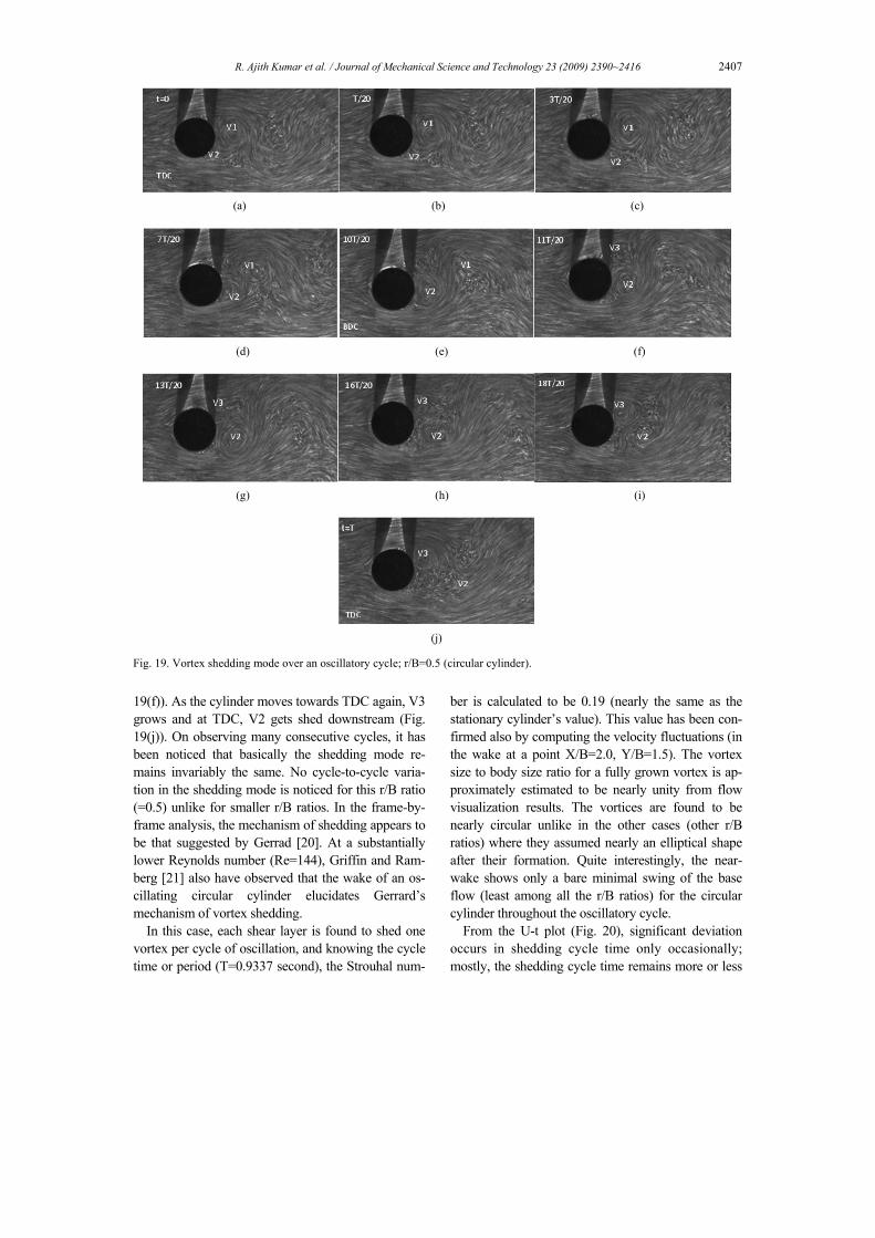
R. Ajith Kumar et al. / Journal of Mechanical Science and Technology 23 (2009) 2390~2416 2407
19(f)). As the cylinder moves towards TDC again, V3 grows and at TDC, V2 gets shed downstream (Fig. 19(j)). On observing many consecutive cycles, it has been noticed that basically the shedding mode re-mains invariably the same. No cycle-to-cycle varia-tion in the shedding mode is noticed for this r/B ratio (=0.5) unlike for smaller r/B ratios. In the frame-by-frame analysis, the mechanism of shedding appears to be that suggested by Gerrad [20]. At a substantially lower Reynolds number (Re=144), Griffin and Ram-berg [21] also have observed that the wake of an os-cillating circular cylinder elucidates Gerrard’s mechanism of vortex shedding.
In this case, each shear layer is found to shed one vortex per cycle of oscillation, and knowing the cycle time or period (T=0.9337 second), the Strouhal num-
ber is calculated to be 0.19 (nearly the same as the stationary cylinder’s value). This value has been con-firmed also by computing the velocity fluctuations (in the wake at a point X/B=2.0, Y/B=1.5). The vortex size to body size ratio for a fully grown vortex is ap-proximately estimated to be nearly unity from flow visualization results. The vortices are found to be nearly circular unlike in the other cases (other r/B ratios) where they assumed nearly an elliptical shape after their formation. Quite interestingly, the near-wake shows only a bare minimal swing of the base flow (least among all the r/B ratios) for the circular cylinder throughout the oscillatory cycle.
From the U-t plot (Fig. 20), significant deviation occurs in shedding cycle time only occasionally; mostly, the shedding cycle time remains more or less
(a) (b) (c)
(d) (e) (f)
(g) (h) (i)
(j)
Fig. 19. Vortex shedding mode over an oscillatory cycle; r/B=0.5 (circular cylinder).
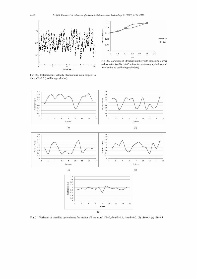
2408 R. Ajith Kumar et al. / Journal of Mechanical Science and Technology 23 (2009) 2390~2416
Fig. 20. Instantaneous velocity fluctuations with respect to time; r/B=0.5 (oscillating cylinder).
Fig. 22. Variation of Strouhal number with respect to corner radius ratio (suffix ‘stat’ refers to stationary cylinders and ‘osc’ refers to oscillating cylinders).
(a) (b)
(c) (d)
(e)
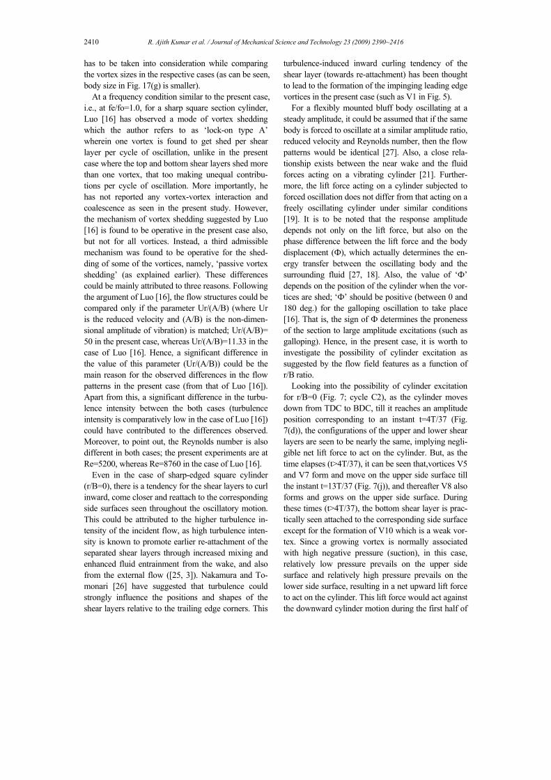
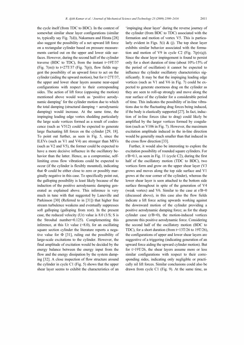
Fig. 21. Variation of shedding cycle timing for various r/B ratios; (a) r/B=0, (b) r/B=0.1, (c) r/B=0.2, (d) r/B=0.3, (e) r/B=0.5.
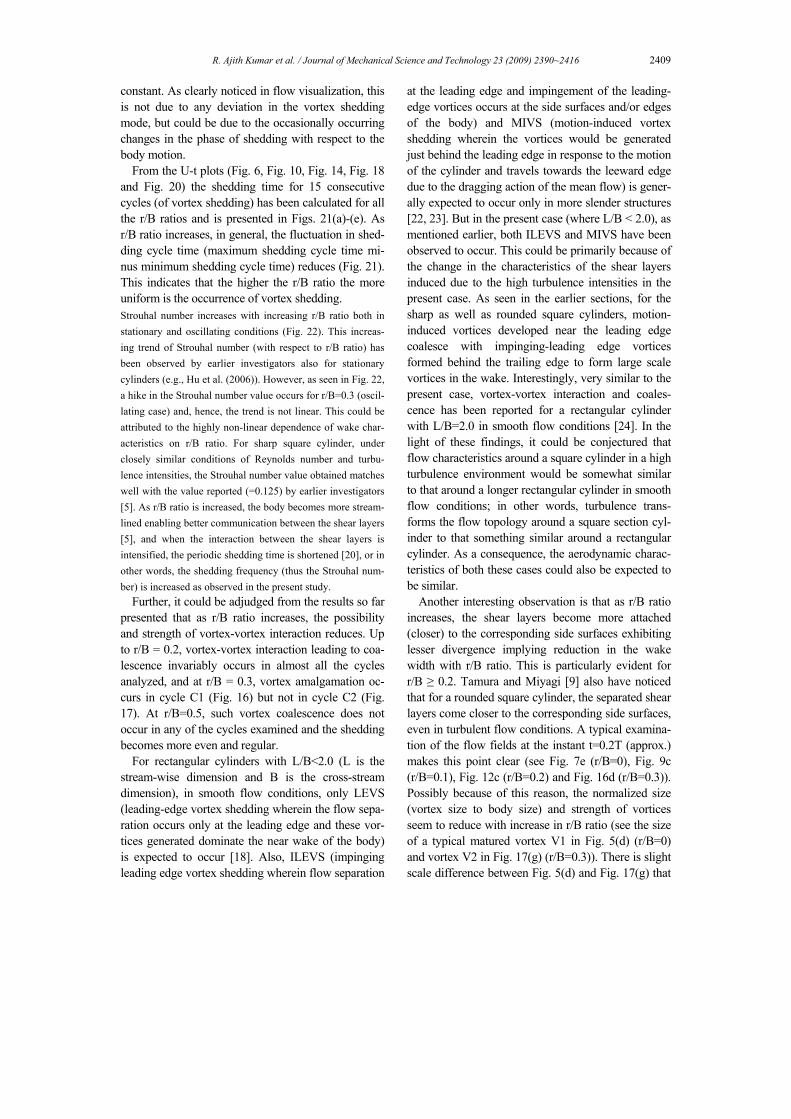
R. Ajith Kumar et al. / Journal of Mechanical Science and Technology 23 (2009) 2390~2416 2409
constant. As clearly noticed in flow visualization, this is not due to any deviation in the vortex shedding mode, but could be due to the occasionally occurring changes in the phase of shedding with respect to the body motion.
From the U-t plots (Fig. 6, Fig. 10, Fig. 14, Fig. 18 and Fig. 20) the shedding time for 15 consecutive cycles (of vortex shedding) has been calculated for all the r/B ratios and is presented in Figs. 21(a)-(e). As r/B ratio increases, in general, the fluctuation in shed-ding cycle time (maximum shedding cycle time mi-nus minimum shedding cycle time) reduces (Fig. 21). This indicates that the higher the r/B ratio the more uniform is the occurrence of vortex shedding. Strouhal number increases with increasing r/B ratio both in stationary and oscillating conditions (Fig. 22). This increas-ing trend of Strouhal number (with respect to r/B ratio) has been observed by earlier investigators also for stationary cylinders (e.g., Hu et al. (2006)). However, as seen in Fig. 22, a hike in the Strouhal number value occurs for r/B=0.3 (oscil-lating case) and, hence, the trend is not linear. This could be attributed to the highly non-linear dependence of wake char-acteristics on r/B ratio. For sharp square cylinder, under closely similar conditions of Reynolds number and turbu-lence intensities, the Strouhal number value obtained matches well with the value reported (=0.125) by earlier investigators [5]. As r/B ratio is increased, the body becomes more stream-lined enabling better communication between the shear layers [5], and when the interaction between the shear layers is intensified, the periodic shedding time is shortened [20], or in other words, the shedding frequency (thus the Strouhal num-ber) is increased as observed in the present study.
Further, it could be adjudged from the results so far presented that as r/B ratio increases, the possibility and strength of vortex-vortex interaction reduces. Up to r/B = 0.2, vortex-vortex interaction leading to coa-lescence invariably occurs in almost all the cycles analyzed, and at r/B = 0.3, vortex amalgamation oc-curs in cycle C1 (Fig. 16) but not in cycle C2 (Fig. 17). At r/B=0.5, such vortex coalescence does not occur in any of the cycles examined and the shedding becomes more even and regular.
For rectangular cylinders with L/B<2.0 (L is the stream-wise dimension and B is the cross-stream dimension), in smooth flow conditions, only LEVS (leading-edge vortex shedding wherein the flow sepa-ration occurs only at the leading edge and these vor-tices generated dominate the near wake of the body) is expected to occur [18]. Also, ILEVS (impinging leading edge vortex shedding wherein flow separation
at the leading edge and impingement of the leading-edge vortices occurs at the side surfaces and/or edges of the body) and MIVS (motion-induced vortex shedding wherein the vortices would be generated just behind the leading edge in response to the motion of the cylinder and travels towards the leeward edge due to the dragging action of the mean flow) is gener-ally expected to occur only in more slender structures [22, 23]. But in the present case (where L/B < 2.0), as mentioned earlier, both ILEVS and MIVS have been observed to occur. This could be primarily because of the change in the characteristics of the shear layers induced due to the high turbulence intensities in the present case. As seen in the earlier sections, for the sharp as well as rounded square cylinders, motion-induced vortices developed near the leading edge coalesce with impinging-leading edge vortices formed behind the trailing edge to form large scale vortices in the wake. Interestingly, very similar to the present case, vortex-vortex interaction and coales-cence has been reported for a rectangular cylinder with L/B=2.0 in smooth flow conditions [24]. In the light of these findings, it could be conjectured that flow characteristics around a square cylinder in a high turbulence environment would be somewhat similar to that around a longer rectangular cylinder in smooth flow conditions; in other words, turbulence trans-forms the flow topology around a square section cyl-inder to that something similar around a rectangular cylinder. As a consequence, the aerodynamic charac-teristics of both these cases could also be expected to be similar.
Another interesting observation is that as r/B ratio increases, the shear layers become more attached (closer) to the corresponding side surfaces exhibiting lesser divergence implying reduction in the wake width with r/B ratio. This is particularly evident for r/B ≥ 0.2. Tamura and Miyagi [9] also have noticed that for a rounded square cylinder, the separated shear layers come closer to the corresponding side surfaces, even in turbulent flow conditions. A typical examina-tion of the flow fields at the instant t=0.2T (approx.) makes this point clear (see Fig. 7e (r/B=0), Fig. 9c (r/B=0.1), Fig. 12c (r/B=0.2) and Fig. 16d (r/B=0.3)). Possibly because of this reason, the normalized size (vortex size to body size) and strength of vortices seem to reduce with increase in r/B ratio (see the size of a typical matured vortex V1 in Fig. 5(d) (r/B=0) and vortex V2 in Fig. 17(g) (r/B=0.3)). There is slight scale difference between Fig. 5(d) and Fig. 17(g) that
2410 R. Ajith Kumar et al. / Journal of Mechanical Science and Technology 23 (2009) 2390~2416
has to be taken into consideration while comparing the vortex sizes in the respective cases (as can be seen, body size in Fig. 17(g) is smaller).
At a frequency condition similar to the present case, i.e., at fe/fo=1.0, for a sharp square section cylinder, Luo [16] has observed a mode of vortex shedding which the author refers to as ‘lock-on type A’ wherein one vortex is found to get shed per shear layer per cycle of oscillation, unlike in the present case where the top and bottom shear layers shed more than one vortex, that too making unequal contribu-tions per cycle of oscillation. More importantly, he has not reported any vortex-vortex interaction and coalescence as seen in the present study. However, the mechanism of vortex shedding suggested by Luo [16] is found to be operative in the present case also, but not for all vortices. Instead, a third admissible mechanism was found to be operative for the shed-ding of some of the vortices, namely, ‘passive vortex shedding’ (as explained earlier). These differences could be mainly attributed to three reasons. Following the argument of Luo [16], the flow structures could be compared only if the parameter Ur/(A/B) (where Ur is the reduced velocity and (A/B) is the non-dimen-sional amplitude of vibration) is matched; Ur/(A/B)= 50 in the present case, whereas Ur/(A/B)=11.33 in the case of Luo [16]. Hence, a significant difference in the value of this parameter (Ur/(A/B)) could be the main reason for the observed differences in the flow patterns in the present case (from that of Luo [16]). Apart from this, a significant difference in the turbu-lence intensity between the both cases (turbulence intensity is comparatively low in the case of Luo [16]) could have contributed to the differences observed. Moreover, to point out, the Reynolds number is also different in both cases; the present experiments are at Re=5200, whereas Re=8760 in the case of Luo [16].
Even in the case of sharp-edged square cylinder (r/B=0), there is a tendency for the shear layers to curl inward, come closer and reattach to the corresponding side surfaces seen throughout the oscillatory motion. This could be attributed to the higher turbulence in-tensity of the incident flow, as high turbulence inten-sity is known to promote earlier re-attachment of the separated shear layers through increased mixing and enhanced fluid entrainment from the wake, and also from the external flow ([25, 3]). Nakamura and To-monari [26] have suggested that turbulence could strongly influence the positions and shapes of the shear layers relative to the trailing edge corners. This
turbulence-induced inward curling tendency of the shear layer (towards re-attachment) has been thought to lead to the formation of the impinging leading edge vortices in the present case (such as V1 in Fig. 5).
For a flexibly mounted bluff body oscillating at a steady amplitude, it could be assumed that if the same body is forced to oscillate at a similar amplitude ratio, reduced velocity and Reynolds number, then the flow patterns would be identical [27]. Also, a close rela-tionship exists between the near wake and the fluid forces acting on a vibrating cylinder [21]. Further-more, the lift force acting on a cylinder subjected to forced oscillation does not differ from that acting on a freely oscillating cylinder under similar conditions [19]. It is to be noted that the response amplitude depends not only on the lift force, but also on the phase difference between the lift force and the body displacement (Ф), which actually determines the en-ergy transfer between the oscillating body and the surrounding fluid [27, 18]. Also, the value of ‘Ф’ depends on the position of the cylinder when the vor-tices are shed; ‘Ф’ should be positive (between 0 and 180 deg.) for the galloping oscillation to take place [16]. That is, the sign of Ф determines the proneness of the section to large amplitude excitations (such as galloping). Hence, in the present case, it is worth to investigate the possibility of cylinder excitation as suggested by the flow field features as a function of r/B ratio.
Looking into the possibility of cylinder excitation for r/B=0 (Fig. 7; cycle C2), as the cylinder moves down from TDC to BDC, till it reaches an amplitude position corresponding to an instant t=4T/37 (Fig. 7(d)), the configurations of the upper and lower shear layers are seen to be nearly the same, implying negli-gible net lift force to act on the cylinder. But, as the time elapses (t>4T/37), it can be seen that,vortices V5 and V7 form and move on the upper side surface till the instant t=13T/37 (Fig. 7(j)), and thereafter V8 also forms and grows on the upper side surface. During these times (t>4T/37), the bottom shear layer is prac-tically seen attached to the corresponding side surface except for the formation of V10 which is a weak vor-tex. Since a growing vortex is normally associated with high negative pressure (suction), in this case, relatively low pressure prevails on the upper side surface and relatively high pressure prevails on the lower side surface, resulting in a net upward lift force to act on the cylinder. This lift force would act against the downward cylinder motion during the first half of
R. Ajith Kumar et al. / Journal of Mechanical Science and Technology 23 (2009) 2390~2416 2411
the cycle itself (from TDC to BDC). In the context of somewhat similar shear layer configurations (similar to, typically say Fig. 7(d)), Nakamura and Hirata [28] also suggest the possibility of a net upward lift force on a rectangular cylinder based on pressure measure-ments carried out on the upper and lower side sur-faces. However, during the second half of the cylinder traverse (BDC to TDC), from the instant t=19T/37 (Fig. 7(m)) to t=27T/37 (Fig. 7(p)), flow fields sug-gest the possibility of an upward force to act on the cylinder (aiding the upward motion), but for t>27T/37, the upper and lower shear layers assume near-equal configurations with respect to their corresponding sides. The action of lift force (opposing the motion) mentioned above would work as ‘positive aerody-namic damping’ for the cylinder motion due to which the total damping (structural damping + aerodynamic damping) would increase. At the same time, the impinging leading edge vortex shedding particularly the large scale vortices formed as a result of coales-cence (such as V512) could be expected to generate large fluctuating lift forces on the cylinder [29, 18]. To point out further, as seen in Fig. 5, since the ILEVs (such as V1 and V4) are stronger than MIVs (such as V2 and V5), the former could be expected to have a more decisive influence in the oscillatory be-havior than the latter. Hence, as a compromise, self-limiting cross flow vibrations could be expected to occur (if the cylinder is flexibly mounted), indicating that Ф could be either close to zero or possibly mar-ginally negative in this case. To specifically point out, the galloping possibility is least likely because of the induction of the positive aerodynamic damping gen-erated as explained above. This inference is very much in tune with that suggested by Laneville and Parkinson [30] (Referred to in [31]) that higher free stream turbulence weakens and eventually suppresses soft galloping (galloping from rest). In the present case, the reduced velocity (Ur) value is 8.0 (1/S; S is the Strouhal number=0.125). Complementing this inference, at this Ur value (=8.0), for an oscillating square section cylinder the literature reports a nega-tive value for Ф [31], ruling out the possibility of large-scale excitations to the cylinder. However, the final amplitude of excitation would be decided by the energy balance between the energy input from the flow and the energy dissipation by the system damp-ing [32]. A close inspection of flow structure around the cylinder in cycle C1 (Fig. 5) shows that the upper shear layer seems to exhibit the characteristics of an
‘impinging shear layer’ during the reverse journey of the cylinder (from BDC to TDC) associated with the formation and motion of vortex V5. This is particu-larly evident in Figs. 5(i) & (j). The top shear layer exhibits similar behavior associated with the forma-tion and motion of V9 in cycle C2 (Fig. 7(p)-(q)). Since the shear layer impingement is found to persist only for a short duration of time (about 10%-15% of the period of oscillation) it cannot be expected to influence the cylinder oscillatory characteristics sig-nificantly. It may be that the impinging leading edge vortices (such as V1 and V6 in Fig. 7) could be ex-pected to generate enormous drag on the cylinder as they are seen to roll-up strongly and move along the rear surface of the cylinder for a considerable period of time. This indicates the possibility of in-line vibra-tions due to the fluctuating drag forces being induced, if the body is elastically supported [27]. In fact, induc-tion of in-line forces (due to drag) could likely be amplified by the larger vortices formed by coagula-tion (such as V106 in Fig. 7). However, the maximum excitation amplitude induced in the in-line direction would be generally much smaller than that induced in the cross flow direction [33].
Further, it would also be interesting to explore the excitation possibility of rounded square cylinders. For r/B=0.1, as seen in Fig. 11 (cycle C2), during the first half of the oscillatory motion (TDC to BDC), two vortices form and grow on the upper shear layer (V3 grows and moves along the top side surface and V1 grows at the rear corner of the cylinder), whereas the lower shear layer is seen attached to the bottom side surface throughout in spite of the generation of V4 (weak vortex) and V6. Similar to the case at r/B=0 (discussed above), in this case also the flow fields indicate a lift force acting upwards working against the downward motion of the cylinder providing a positive aerodynamic damping force; as for the sharp cylinder case (r/B=0), the motion-induced vortices generate this positive aerodynamic force. Considering the second half of the oscillatory motion (BDC to TDC), for a short duration (from t=13T/26 to 19T/26), the configurations of upper and lower shear layers are suggestive of a triggering (indicating generation of an upward force aiding the upward cylinder motion). But for t>19T/26, the shear layers assume more or less similar configurations with respect to their corre-sponding sides, indicating only negligible or practi-cally nil lift forces. Similar conclusions could also be drawn from cycle C1 (Fig. 9). At the same time, as
2412 R. Ajith Kumar et al. / Journal of Mechanical Science and Technology 23 (2009) 2390~2416
indicated for r/B=0, significant lift forces could be expected to be developed by the shedding of impinging leading edge vortices, particularly by the large scale coalesced vortices (such as V31 in Fig. 11). Impingement of upper shear layer associated with the motion of V5 (Fig. 11(n)-(p)) cannot be expected to generate significant pressure variations on the top side surface since it occurs only for a short time interval similar to the sharp cylinder case. However, when compared to r/B=0 case, the shear layer deflection and the wake width have marginally come down. Hence, a similar excitation level as that of the sharp cylinder but with reduced magnitude could be ex-pected in this case. Quite similar to the case with r/B=0, there could be considerable drag forces (in-line force) acting on the cylinder predominantly due to the formation and action of ILEVs (such as V1 and V6) formed at the rear corners of the cylinder.
For r/B=0.2, as Fig. 15 shows, starting from TDC to BDC, a bottom shear layer forms and sheds vortex V3, and thereafter an upper shear layer forms and sheds vortex V2. As both these vortices are small-scale (feeble) vortices, they cannot be expected to create significant pressure difference between the upper and lower side surfaces leading to oscillations. In the reverse journey of the cylinder also (BDC to TDC), a similar flow situation prevails wherein the configurations of the shear layers are not significantly different unlike in the cases with r/B=0 and 0.1. This implies that when compared to the cases with r/B=0 and 0.1, the positive aerodynamic damping is possi-bly reduced to a much lower value. It could also be seen that both the shear layers show greater tendency to re-attach on to the corresponding sides further re-ducing the wake width (compared to the cases with smaller r/B ratios). The strength of vortices (inferred from the vortex size) also appears to have come down. Hence, accounting for all these factors and also con-sidering lift force generation due to the impinging leading edge vortex shedding (such as V1 and V4) from the cylinder, it is suggested that an excitation (such as vortex resonance) is possible but with re-duced magnitude compared to that at smaller r/B ratios. An analysis of cycle C1 (Fig. 12) would also reveal the same fact. However, as in the previous cases (r/B=0, 0.1), in this case also, the flow field suggests that the cylinder could be subjected to sig-nificant drag force due to the action of ILEVs (such as V1 and V2). But, it is interesting that the rolling up of these vortices seems to be weaker with smaller size
(hence, lesser circulation) when compared to those in the previous cases (r/B=0, 0.1), implying a possible reduction in the drag force.
At r/B=0.3 also (Fig. 17; cycle C2), the flow field looks to be quite similar to that at r/B=0.2 but with stronger re-attachment of the shear layers on to the cylinder sides. Both the upper and lower shear layers are closely attached to the corresponding side surfaces throughout the oscillatory cycle. Both the shear layers are seen to be more inwardly curled (towards the wake centerline) with the separation bubble formation and the subsequent venting process [34] significantly reduced. Furthermore, the vortices formed (both ILEVs and MIVs) are seen to be weaker and with smaller size (compared to those at smaller r/B ratios). However, cycle C1 (Fig. 16) shows the possibility of the induction of small scale positive aerodynamic damping during the first half of the oscillatory cycle and also the possibility of small scale negative aero-dynamic damping during a short duration in the sec-ond half of the cycle. Similar to the other r/B ratios, in this case also, some lift force generation could be expected to occur due to the ILEVs. However, as indicated earlier, only weaker lift force could be ex-pected (than at other r/B ratios) due to weaker vortex shedding. Hence, overall, it could be concluded that, at this increased r/B ratio (=0.3), the cylinder could possibly be excited to vibrations but with still less-ened amplitude levels (compared to the smaller r/B ratios). Also, due to the greater re-attaching and in-wardly curled nature of the shear layers, the wake width and consequently the drag force would possibly be much lower in this case.
It is to be specifically pointed out that for all the cases with r/B ≤ 0.3, as described above, cycle-to-cycle variation in the mode of vortex shedding and strong vortex-vortex interactions occur, possibly lead-ing to coalescence. This could be certainly expected to induce large scale non-linearities in the wake char-acteristics, particularly in the pressure distribution on the cylinder side walls, which could possibly become highly unsteady. This indicates that the cylinders could possibly experience unsteady response ampli-tudes somewhat similar to multiple amplitudes ob-served by Ajith Kumar and Gowda [17] and Waw-zonek [35] (referred to in [36]) for a square section cylinder. Hence, the dependence of aerodynamic characteristics on r/B ratio need not necessarily be linear, or in other words, could possibly be non-linear in nature.
R. Ajith Kumar et al. / Journal of Mechanical Science and Technology 23 (2009) 2390~2416 2413
When the r/B ratio is further increased to its maxi-mum value (=0.5), the resulting flow field shows the existence of regular vortex shedding from the cylin-der as depicted in Fig. 19. The flow field is quite sug-gestive of an excitation possibility for the cylinder due to vortex resonance. However, for a single circu-lar section, very large oscillations (galloping) cannot be expected to occur [37, 38]). Further, free stream turbulence intensity of up to 10% would not have a significant influence either on the oscillating lift coef-ficient or vortex-induced vibration of circular cylin-ders [39, 40]. Hence, in the present case (where the turbulence intensity is 6.5%), the circular cylinder could be expected to undergo vortex-induced vibra-tions with an excitation level similar to that in a low turbulence environment. Additionally, the dynamics of cylinder vibration also depends on the nature of the separation points [41]. For a circular cylinder, the separation points oscillate over a range of 75-85 deg. [42]. Following the argument of Wang and Zhou [41], due to the oscillating flow separation points, there would be span-wise discrepancy in vortex shedding from a circular cylinder, i.e., the vortex shedding would be more or less three-dimensional in nature, whereas the vortex shedding from a sharp square cylinder is more likely to be coherent in the span-wise direction. Because of this, excitation levels are likely to be lesser for a circular cylinder than for a sharp square cylinder under similar conditions. Literature confirms this possibility. At a free stream turbulence intensity of less than 1% and at low damping condi-tions, Gowda and Sreedharan [43] report a peak-to-peak amplitude value equal to 13% of the diameter of the cylinder at a reduced velocity value of 5.3 (present case value for circular cylinder). It is interesting that under closely similar conditions, a square cylinder was found to exhibit a higher peak-to-peak amplitude value equal to 16% of the cylinder side dimension [44].
As r/B ratio increases, the magnitude of positive damping force reduces together with a reduction in the wake width, and also the vortex strength indicat-ing that the excitation amplitude would possibly re-duce with increasing r/B ratio. That is, increasing corner rounding would suppress instability of the cylinder [7, 9]. However, apart from other factors such as mass damping parameter, fluid and flow characteristics, significant oscillations could be trig-gered only if the aspect ratio (height to characteristic dimension ratio) is greater than 5.0 since it decisively
influences the span-wise correlation of vortex shed-ding [27].
A sharp square section is known to experience gal-loping excitation, depending on the flow conditions and damping [45]. Particularly, galloping oscillations could occur only if motion-aiding forces are gener-ated which would act as ‘negative aerodynamic damping’ on the structure [18]. But, in the present case, this possibility is not suggested by the flow fields as discussed earlier. Instead, positive aerody-namic damping forces are generated due to the forma-tion and action of motion-induced vortices. These motion-induced vortices are thought to have gener-ated due to the change in the characteristics of the shear layers brought about by the influence of high turbulence intensity.
It is noteworthy that the base swing motion reduces as r/B ratio increases, as the present results show and is found to be the least for the circular cylinder (as mentioned in above sections). On the contrary, for a circular cylinder, Ongoren and Rockwell [15] have observed base swing motion, whereas for a square cylinder they have not. Their experiments were con-ducted at a much lower Re value (=855) and pre-sumably at smooth flow conditions. They have attrib-uted the base swing to the switch in the phase of ini-tially shed vortex at fe/fo~1.0. In the present case, also, for the circular cylinder, such a phase switch was observed at fe/fo = 0.96 (but details are not pre-sented here) but not observed for square cylinder. It is strongly felt that Ongoren and Rockwell [15] have not considered an important aspect as far as a circular cylinder is concerned even in smooth flow conditions. That is, the motion of shear layers with respect to the body motion or, in other words, the relative motion of shear layers (across the flow). This is in addition to the motion of the separation points and thus of the shear layers (more or less in the stream-wise direc-tion). Furthermore, in case of turbulent oncoming flow, as mentioned in earlier sections, the shear layer characteristics would change with turbulence induc-ing in them an inwardly curling tendency (towards the wake centerline). Hence, the absence of base swing for circular cylinder (observed in the present case) may be primarily due to the cancellation of opposing tendencies on the wake motion caused by the action of phase switch in one direction, and relative motion of shear layers combined with inwardly curling action in the opposite direction. For the square section cylin-der, the base swing observed in the present case could
2414 R. Ajith Kumar et al. / Journal of Mechanical Science and Technology 23 (2009) 2390~2416
be attributed to the relative motion of shear layers coupled with the inward curling tendency of shear layers. Hence, the fixed nature of the separation points is not sufficient to preclude this base swing, particularly in a turbulent environment. For other r/B ratios, particularly for r/B>0.1, the re-attachment of both the shear layers onto their corresponding side surfaces is found to strongly restrict (or control) the relative motion of shear layers due to which the swing of the base region substantially comes down; this re-attachment of shear layers is thought to have been aided by the mobility of the separation points at the cylinder corners. However, for the circular cylinder, this shear layer control mechanism (due to re-attachment) cannot operate since it does not have a significant afterbody.
4. Conclusions
The influence of a corner radius of a square section cylinder on the mode and mechanism of vortex shed-ding and also on other aerodynamic characteristics is discussed. The investigation has been conducted by using the PIV technique. This study brings out the following conclusions.
The near wake flow structure is found to signifi-cantly depend on the corner radius of the cylinder. Except for r/B=0.5, for all the other cases of r/B ratios, cycle-to cycle variation in the mode of vortex shed-ding was observed in the case of oscillating cylinders inducing highly non-linear wake characteristics. The modes of vortex shedding were characterized by vor-tex-vortex interactions sometimes leading to coales-cence (and sometimes not). Cycle-to-cycle variation in mode of vortex shedding is found to give rise to highly non-uniform shedding. Higher the r/B ratio, shedding in the near wake was found to be more uni-form. The near wake of cylinders is found to exhibit motion-induced vortex shedding as well as impinging leading edge vortex shedding unlike that of stationary cylinder wherein the near wake is known to exhibit regular Karman vortex shedding.
The flow fields suggest that the dependence of aerodynamic characteristics on r/B ratio could be non-linear in nature as being shown by the non-linearly increasing trend of Strouhal number with respect to r/B ratio in the oscillating cylinder case.
Apart from the accepted shedding mechanisms, an-other admissible shedding mechanism is newly iden-tified to operate in the near wake of oscillating cylin-
ders now being called as the ‘passive shedding’ mechanism. Unlike the existing shedding mecha-nisms (now being called as the ‘active shedding’ mechanisms), the vorticity supply to the vortex being shed is not actually cut and the grown vortex is merely pushed downstream by its co-generated vortex.
The results indicate that increasing the corner ra-dius reduces the proneness of section to flow-induced vibrations or, in other words suppresses the instabili-ties of the section.
Acknowledgment
This work was supported by the Brain Korea 21 project and the Grant of the Korean Ministry of Edu-cation, Science and Technology (The Regional Core Research Program).
References
[1] G. V. Parkinson, Wind induced instability of struc-tures, Phil.Trans.Roy.Soc.Lon. A 269 (1971) 395-409.
[2] K. Washizu, A. Ohya, Y. Otsuki and K. Fuji, Aeroe-lastic instability of rectangular cylinders in a heav-ing mode, J.Sound Vib.59 (1978) 195-210.
[3] Y. Nakamura, Bluff-Body Aerodynamics and Tur-bulence, J.Wind Eng.Ind.Aerodyn. 49 (1993) 65-78.
[4] E. Naudascher, J.R. Weske and B. Fey, Exploratory study on damping of galloping vibrations, J.Wind Eng.Ind.Aerodyn 8 (1981) 211-222.
[5] A. R. Bokaian and F. Geoola, Hydroelastic instabili-ties of square cylinders, J.Sound Vib. 92 (1984) 117-141.
[6] K. C. S. Kwok, P. A, Wilhelm and B. G. Wilkie, Effect of edge configuration on wind-induced re-sponse of a tall building, Eng.Struct. 10 (1988) 135-140.
[7] H. Kawai, Effect of corner modifications on aeroe-lastic instabilities of tall buildings, J.Wind Eng.Ind.Aerodyn. 74-76 (1998) 719-729.
[8] T. Tamura, T. Miyagi and T. Kitagishi, Numerical prediction of unsteady pressures on a square cylin-der with various corner shapes, J.Wind Eng.Ind.Aerodyn. 74-76 (1998) 531-542.
[9] T. Tamura and T. Miyagi, The effect of turbulence on aerodynamic forces on a square cylinder with various corner shapes, J.Wind Eng.Ind.Aerodyn 83 (1999) 135-145.
[10] C. Dalton and W. Zheng, Numerical solutions of a

R. Ajith Kumar et al. / Journal of Mechanical Science and Technology 23 (2009) 2390~2416 2415
viscous uniform approach flow past square and dia-mond cylinders, J.Fluids Struct. 18 (2003) 455-465.
[11] J. C. Hu, Y. Zhou and C. Dalton, Effects of the corner radius on the near wake of a square prism, Exp Fluid 40 (2006) 106-118.
[12] N. K. Delany and N. E. Sorensen, Low-speed drag of cylinder of various shapes, NACA Technical notes 3038 (1953).
[13] P. W. Bearman, J. M. R. Graham, E. D. Obasaju and G. M. Drossopoulos, The influence of corner radius on the forces experienced by cylindrical bod-ies in oscillatory flow, Appl.Ocean Res. 6 (1984) 83-89.
[14] W. Zheng and C. Dalton, Numerical prediction of force on rectangular cylinders in oscillating viscous flow, J Fluids Struct 13 (1999) 225-249.
[15] A. Ongoren and D. Rockwell, Flow structure from an oscillating cylinder Part 1. Mechanisms of phase shift and recovery in the near wake, J Fluid Mech 191 (1988) 197-223.
[16] S. C. Luo, Vortex wake of a transversely oscillat-ing square cylinder: A flow visualization analysis, J.Wind Eng.Ind.Aerodyn 45 (1992) 97-119.
[17] R. Ajith Kumar and B. H. L. Gowda, Flow-induced vibration of a square cylinder without and with interference, J Fluids Struct 22 (2006) 345-369.
[18] S. Deniz and Th. Staubli, Oscillating rectangular and octagonal profiles: Interaction of leading-and-trailing edge vortex formation, J Fluids Struct 11 (1997) 3-31.
[19] S. Komatsu and H. Kobayashi, Vortex-induced oscillation of bluff cylinders, J.Wind Eng.Ind.Aerodyn 6 (1980) 335-362.
[20] J. H. Gerrard, The mechanics of the formation region of vortices behind bluff bodies, J. Fluid Mech. 25 (1966) 401-413.
[21] O. M. Griffin and S. E. Ramberg, The vortex-street wakes of vibrating cylinders, J. Fluid Mech. 66 (1974) 553-576.
[22] P. Hemon and F. Santi, On the aeroelastic behavior of rectangular cylinders in cross-flow, J Fluids Struct 16(7) (2002) 855-889.
[23] M. Matsumoto, N. Shiraishi, H. Shirato, S. Stoy-anoff and T. Yagi, Mechanism of, and turbulence ef-fect on vortex-induced oscillations for bridge box girders, J.Wind Eng.Ind.Aerodyn 49 (1993) 467-476.
[24] N. Shiraishi and M. Matsumoto, On classification of vortex-induced oscillation and its application for bridge structures, J.Wind Eng.Ind.Aerodyn 14 (1983) 419-430.
[25] K. C. S. Kwok, Effects of turbulence on the pres-sure distribution around a square cylinder and pos-sibility of reduction, J.Fluids Eng. 105 (1983) 140-145.
[26] Y. Nakamura and Y. Tomonari, Galloping of rec-tangular prisms in a smooth and in a turbulent flow, J Sound Vib. 52(2) (1977) 233-241.
[27] P. W. Bearman, Vortex shedding from oscillating bluff bodies, Annu. Rev. Fluid Mech. 16 (1984) 195-222.
[28] Y. Nakamura and K. Hirata, Pressure fluctuations on oscillating rectangular cylinders with the long side normal to the flow, J. Fluids Struct. 5 (1991) 165-183.
[29] E. Naudascher and Y. Wang, Flow-induced vibra-tions of prismatic bodies and grids of prisms, J. Flu-ids Struct. 7 (1993) 341-373.
[30] A. Laneville and G. V. Parkinson, 1971. Proc. 3rd International Conference on Wind Effects on Build-ings & Structures, Saikon, Tokyo, 787-797 (not seen the original; referred in [30]).
[31] Y. Nakamura, Recent research into bluff-body flutter, J.Wind Eng.Ind.Aerodyn 33 (1990) 1-10.
[32] G. V. Parkinson and P. P. Sullivan, Galloping re-sponse of towers, J. Ind. Aerodyn 4 (1979) 253-260.
[33] O. M. Griffin and S. E. Ramberg, Vortex shedding from a cylinder vibrating in line with an incident uniform flow, J. Fluid Mech. 75 (1976) 257-271.
[34] A. Laneville and Lu Zhi. Yong, Mean flow pat-terns around two-dimensional rectangular cylinders and their interpretation, J.Wind Eng.Ind.Aerodyn. 14 (1983) 387-398.
[35] M. A. Wawzonek, Aeroelastic behavior of square section prisms in uniform flow, Thesis of M.A.Sc, The University of British Colombia (1979) (not seen the original; referred in [36]).
[36] Y. Tamura and K. Shimada, A mathematical model for the transverse oscillations of square cylinders, Proc. International Conference on Flow Induced Vibrations, Bowness-on-Windermere, England: 12-14 May, Paper F4, 267-275.
[37] P. W. Bearman, I. S. Gartshore, D. J. Maull and G. V. Parkinson, Experiments on flow-induced vibra-tion of a square section cylinder, J. Fluids Struct. 1 (1987) 19-34.
[38] Y. Nakamura, K. Hirata, K. Kashima, Galloping of a circular cylinder in the presence of a splitter plate, J. Fluids Struct . 8 (1994) 355-365.
[39] I. S. Gartshore, Some effects of upstream turbu-lence on the unsteady lift forces imposed on pris-
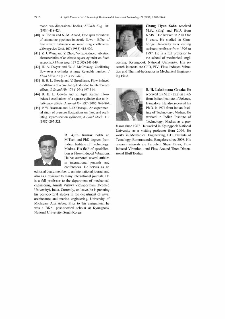
2416 R. Ajith Kumar et al. / Journal of Mechanical Science and Technology 23 (2009) 2390~2416
matic two dimensional bodies, J.Fluids Eng. 106 (1984) 418-424.
[40] A. Torum and N. M. Anand, Free span vibrations of submarine pipelines in steady flows – Effect of free stream turbulence on mean drag coefficients, J.Energy Res Tech. 107 (1985) 415-420.
[41] Z. J. Wang and Y. Zhou, Vortex-induced vibration characteristics of an elastic square cylinder on fixed supports, J Fluids Eng. 127 (2005) 241-249.
[42] H. A. Dwyer and W. J. McCroskey, Oscillating flow over a cylinder at large Reynolds number, J Fluid Mech. 61 (1973) 753-767.
[43] B. H. L. Gowda and V. Sreedharan, Flow-induced oscillations of a circular cylinder due to interference effects, J. Sound Vib. 176 (1994) 497-514.
[44] B. H. L. Gowda and R. Ajith Kumar, Flow-induced oscillations of a square cylinder due to in-terference effects, J. Sound Vib. 297 (2006) 842-864.
[45] P. W. Bearman and E. D. Obasaju, An experimen-tal study of pressure fluctuations on fixed and oscil-lating square-section cylinders, J Fluid Mech. 119 (1982) 297-321.
R. Ajith Kumar holds an M.Tech and PhD degrees from Indian Institute of Technology, Madras. His field of specializa-tion is Flow-Induced Vibrations. He has authored several articles in international journals and conferences. He serves as an
editorial board member to an international journal and also as a reviewer to many international journals. He is a full professor to the department of mechanical engineering, Amrita Vishwa Vidyapeetham (Deemed University), India. Currently, on leave, he is pursuing his post-doctoral studies in the department of naval architecture and marine engineering, University of Michigan, Ann Arbor. Prior to this assignment, he was a BK21 post-doctoral scholar at Kyungpook National University, South Korea.
Chang Hyun Sohn received M.Sc. (Eng) and Ph.D. from KAIST. He worked in ADD for 3 years. He studied in Cam-bridge University as a visiting assistant professor from 1996 to 1997. He is a full professor to the school of mechanical engi-
neering, Kyungpook National University. His re-search interests are CFD, PIV, Flow Induced Vibra-tion and Thermal-hydraulics in Mechanical Engineer-ing Field.
B. H. Lakshmana Gowda: He received his M.E. (Eng) in 1965 from Indian Institute of Science, Bangalore. He also received his Ph.D. in 1974 from Indian Insti-tute of Technology, Madras. He worked in Indian Institute of Technology, Madras as a pro-
fessor since 1967. He worked in Kyungpook National University as a visiting professor from 2004. He works in Mechanical Engineering, BTL Institute of Tecnology, Bommasandra, Bangalore since 2008. His research interests are Turbulent Shear Flows, Flow Induced Vibration and Flow Around Three-Dimen-sional Bluff Bodies.