Embed Size (px)
Citation preview
Manual No. 21117E1.1Published in Jan. 2012Revised in Jul. 2012
infiSYS RV-200 System
VM-781B infiSYS Diagnostic SoftwareOperation Manual
SHINKAWA Sensor Technology, Inc.
• Be sure to read this instruction manual thoroughly and understand the con-tents before using this product.
• Keep this manual so that the operator can refer to it when needed.

infiSYS RV-200 VM-781B Introduction
Introduction
Thank you very much for purchasing the infiSYS RV-200 system (hereafter referred to as “this product”).
<Manuals for the infiSYS RV-200 System>
There are six different kinds of manuals for the infiSYS RV-200 system. Each manual covers different areas of work and/or operations.This manual is one of the six.
Name VM-773B infiSYS Analysis View Operation Manual Setup Guide
Targeted personnel Operators and service personnel who manage the system and perform detailed settings
Content • Overview of the infiSYS RV-200 system• Installing the software• Setting the network• Connecting with devices (monitors, analyzers)
Name VM-773B infiSYS Analysis View Operation Manual Basic Operation Guide
Targeted personnel Operators and service personnel who manage the system, perform detailed settings and check the monitor display
Content • Basic operating procedures for setting, collecting, and displaying data
Name VM-773B infiSYS Analysis View Operation Manual Setting Guide
Targeted personnel Operators and service personnel who manage the system and perform detailed settings
Content • How to set the device(monitors, analyzers) information• How to set the machine information• How to set the database/system information
Name VM-773B infiSYS Analysis View Operation Manual Analysis Guide
Targeted personnel Operators and service personnel who manage the system and perform vibration analysis
Content • How to operate the display program• Operating procedure and functional description for the analysis graph
Name VM-772B Device Config Operation Manual
Targeted personnel Service personnel who set up and maintain the devices (monitors, analyzers)The use of this manual is limited to those who have completed our company's maintenance training course.
Content • Basic operating procedure
Name VM-781B infiSYS Diagnostic Software Operation Manual
Targeted personnel Operators and service personnel who manage the system and perform detailed settings
Content • Overview of the Diagnosis Software• Installing the software• Basic operating procedure
1
infiSYS RV-200 VM-781B Introduction
Important Notification
• Please read this document thoroughly to understand this product well before using it. When you finished reading this document, please keep it in a safe place so that you can refer to it at any time.
• For further questions and enquiry regarding the content of this document and the product, please contact the sales office from which you purchased the product.
• In order to operate this product, in addition to the information contained in this document, you need to have some additional knowledge about instrumentation equipment and transducer to be connected to this product. To ensure safety, you need to understand the content of this document as well as have a general knowledge of safety.
• In case you combine this product with other instrumental equipment to sell or transfer it as a part of an assembly, we advise you to make sure that you attach this document to the product and hand it over to the end user.
• When you dispose of this product, you must follow the laws and regulations of the relevant local government.
• The names of companies and products contained herein are trademarks or registered trademarks of their respective owners.
• The copyright of this document belongs to SHINKAWA Sensor Technology, Inc. Publishing the content of this document without permission or reproducing/copying the document in any way is strictly prohibited.
CAUTION
Loss of USB Protection KeyThis product works in conjunction with the USB protection key included in the package ; hence, the key has the value equivalent to the application software. Please note that the key is not sold by ifself.Be sure to store it in a secure place because if the USB protection key should be lost, the customer would have to purchase another set of the product.
2

infiSYS RV-200 VM-781B Introduction
Disclaimer
• We shall not be held liable for any damage or injury whatsoever arising out of any failure to follow the instructions contained in this document or lack of due care or attention in the use or installation of this product.
• We shall not offer any compensation for damages/injuries, direct or indirect, or lost income caused by any misuse, abuse, alternation or disassembly of this product.
• Unless specifically stated otherwise in this document or in the warranty policy, we do not give any warranty, expressed or implied, including warranty for merchantability, warranty for fitness for particular purpose or use, and warranty for patent infringement.
• Warranty policy of this product is attached at the end of this document. In the event of breakdown of this product, we will repair it based on this warranty policy.
• We shall not be held liable in any way for any outcome resulting from the use of other than recommended parts.
3
infiSYS RV-200 VM-781B Table of Contents
4
Table of Contents
Manuals for the infiSYS RV-200 System ............................................................................................ 1Important Notification .......................................................................................................................... 2Disclaimer .............................................................................................................................................. 3Table of Contents .................................................................................................................................. 4
Chapter 1 Safety Precautions ........................................................................................... 5
1.1 Intended Users of the Manual .............................................................................................. 5
1.2 Warning Symbols ................................................................................................................ 5
Chapter 2 Overview ........................................................................................................... 6
Chapter 3 Diagnostic Program Setup .............................................................................. 8
3.1 Preparation before Installation ............................................................................................ 8
3.2 Installing .............................................................................................................................. 8
Chapter 4 Entering Machine Information Necessary for Diagnosis ............................. 9
4.1 Workflow ............................................................................................................................. 9
4.2 Setting Devices .................................................................................................................... 9
4.3 Registering Devices ............................................................................................................. 9
4.4 Setting the Bearing Information ........................................................................................ 10
4.5 Setting the Machine Information ....................................................................................... 10
Chapter 5 Performing Diagnosis .................................................................................... 11
Chapter 6 Trouble Shooting ........................................................................................... 14
6.1 Trouble Shooting List ........................................................................................................ 14Warranty Policy
infiSYS RV-200 VM-781B Chapter 1 Safety Precautions
5
Chapter 1 Safety Precautions
To ensure the safe use of the product, make sure to read this section.
1.1 Intended Users of the Manual
This document is intended for use to perform detailed settings and maintenance of the product, or to solve problems in the product.Only operators and service personnel who are in charge of system management are allowed to perform operations using this document.
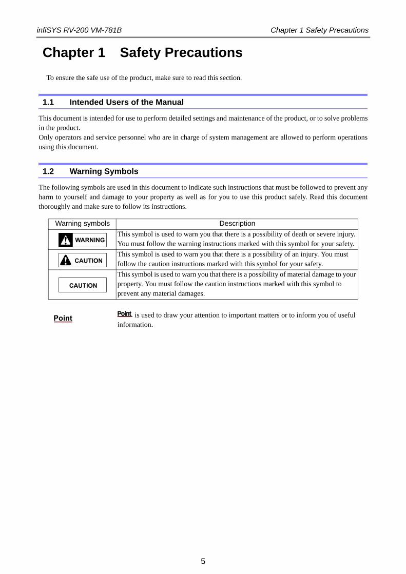
1.2 Warning Symbols
The following symbols are used in this document to indicate such instructions that must be followed to prevent any harm to yourself and damage to your property as well as for you to use this product safely. Read this document thoroughly and make sure to follow its instructions.
Warning symbols Description
This symbol is used to warn you that there is a possibility of death or severe injury. You must follow the warning instructions marked with this symbol for your safety.
This symbol is used to warn you that there is a possibility of an injury. You must follow the caution instructions marked with this symbol for your safety.
This symbol is used to warn you that there is a possibility of material damage to your property. You must follow the caution instructions marked with this symbol to prevent any material damages.
is used to draw your attention to important matters or to inform you of useful information.
WARNING
CAUTION
CAUTION
PointPointPoint
infiSYS RV-200 VM-781B Chapter 2 Overview
Chapter 2 Overview
When added to VM-773B infiSYS Analysis View (hereafter referred to as "Analysis View") or VM-774B infiSYS Remote View (hereafter referred to as "Remote View") Programs, this program performs diagnosis of the rotating machine.
This product has applications to the following rotating machinery with journal bearings or rolling bearings:
• Turbine
• Generator
• Motor
• Blower
• Pump
• Compressor
6
infiSYS RV-200 VM-781B Chapter 2 Overview
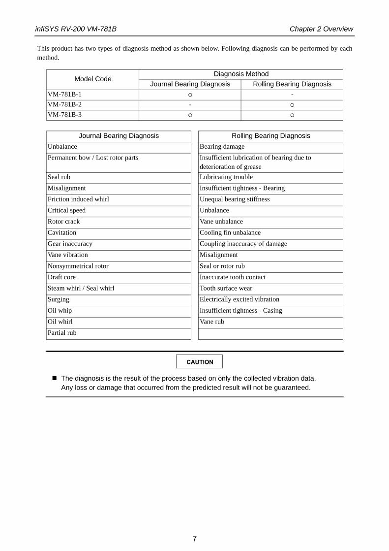
This product has two types of diagnosis method as shown below. Following diagnosis can be performed by each method.
CAUTION
The diagnosis is the result of the process based on only the collected vibration data.Any loss or damage that occurred from the predicted result will not be guaranteed.
Model CodeDiagnosis Method
Journal Bearing Diagnosis Rolling Bearing Diagnosis
VM-781B-1 -
VM-781B-2 -
VM-781B-3
Journal Bearing Diagnosis Rolling Bearing Diagnosis
Unbalance Bearing damage
Permanent bow / Lost rotor parts Insufficient lubrication of bearing due to deterioration of grease
Seal rub Lubricating trouble
Misalignment Insufficient tightness - Bearing
Friction induced whirl Unequal bearing stiffness
Critical speed Unbalance
Rotor crack Vane unbalance
Cavitation Cooling fin unbalance
Gear inaccuracy Coupling inaccuracy of damage
Vane vibration Misalignment
Nonsymmetrical rotor Seal or rotor rub
Draft core Inaccurate tooth contact
Steam whirl / Seal whirl Tooth surface wear
Surging Electrically excited vibration
Oil whip Insufficient tightness - Casing
Oil whirl Vane rub
Partial rub
7
infiSYS RV-200 VM-781B Chapter 3 Diagnostic Program Setup
8
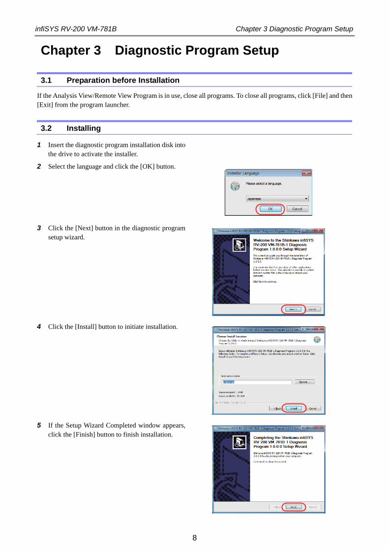
Chapter 3 Diagnostic Program Setup
3.1 Preparation before Installation
If the Analysis View/Remote View Program is in use, close all programs. To close all programs, click [File] and then [Exit] from the program launcher.
3.2 Installing
1 Insert the diagnostic program installation disk into the drive to activate the installer.
2 Select the language and click the [OK] button.
3 Click the [Next] button in the diagnostic program setup wizard.
4 Click the [Install] button to initiate installation.
5 If the Setup Wizard Completed window appears, click the [Finish] button to finish installation.
infiSYS RV-200 VM-781B Chapter 4 Entering Machine Information Necessary for Diagnosis
Chapter 4 Entering Machine Information Necessary for Diagnosis
Machine information entry is required to perform diagnosis.
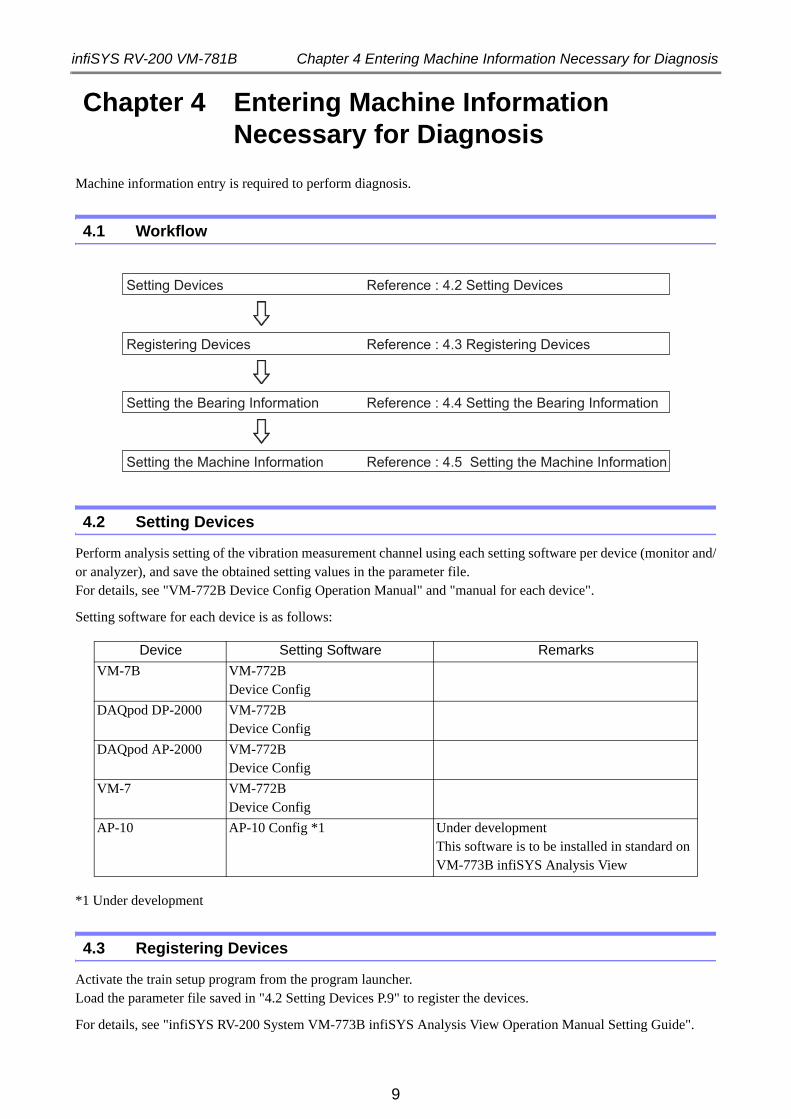
4.1 Workflow
4.2 Setting Devices
Perform analysis setting of the vibration measurement channel using each setting software per device (monitor and/or analyzer), and save the obtained setting values in the parameter file. For details, see "VM-772B Device Config Operation Manual" and "manual for each device".
Setting software for each device is as follows:
*1 Under development
4.3 Registering Devices
Activate the train setup program from the program launcher. Load the parameter file saved in "4.2 Setting Devices P.9" to register the devices.
For details, see "infiSYS RV-200 System VM-773B infiSYS Analysis View Operation Manual Setting Guide".
Device Setting Software Remarks
VM-7B VM-772B Device Config
DAQpod DP-2000 VM-772B Device Config
DAQpod AP-2000 VM-772B Device Config
VM-7 VM-772B Device Config
AP-10 AP-10 Config *1 Under developmentThis software is to be installed in standard on VM-773B infiSYS Analysis View
Setting Devices Reference : 4.2 Setting Devices
Registering Devices Reference : 4.3 Registering Devices
Setting the Bearing Information Reference : 4.4 Setting the Bearing Information
Setting the Machine Information Reference : 4.5 Setting the Machine Information
9
infiSYS RV-200 VM-781B Chapter 4 Entering Machine Information Necessary for Diagnosis
4.4 Setting the Bearing Information
Set the bearing information using the train setup program. This information becomes necessary when performing rolling bearing diagnosis. Enter the bearing information used in the analysis target machine.
For details, see "infiSYS RV-200 System VM-773B infiSYS Analysis View Operation Manual Setting Guide".
4.5 Setting the Machine Information
Set the machine information by creating a machine tree using the train setup program.
For details, see "infiSYS RV-200 System VM-773B infiSYS Analysis View Operation Manual Setting Guide".
10
infiSYS RV-200 VM-781B Chapter 5 Performing Diagnosis
Chapter 5 Performing Diagnosis
1 Activate the display program on the Analysis View or Remote View.
2 Select the measurement point at which you want to perform diagnosis and display the waveform plot or the spectrum plot.
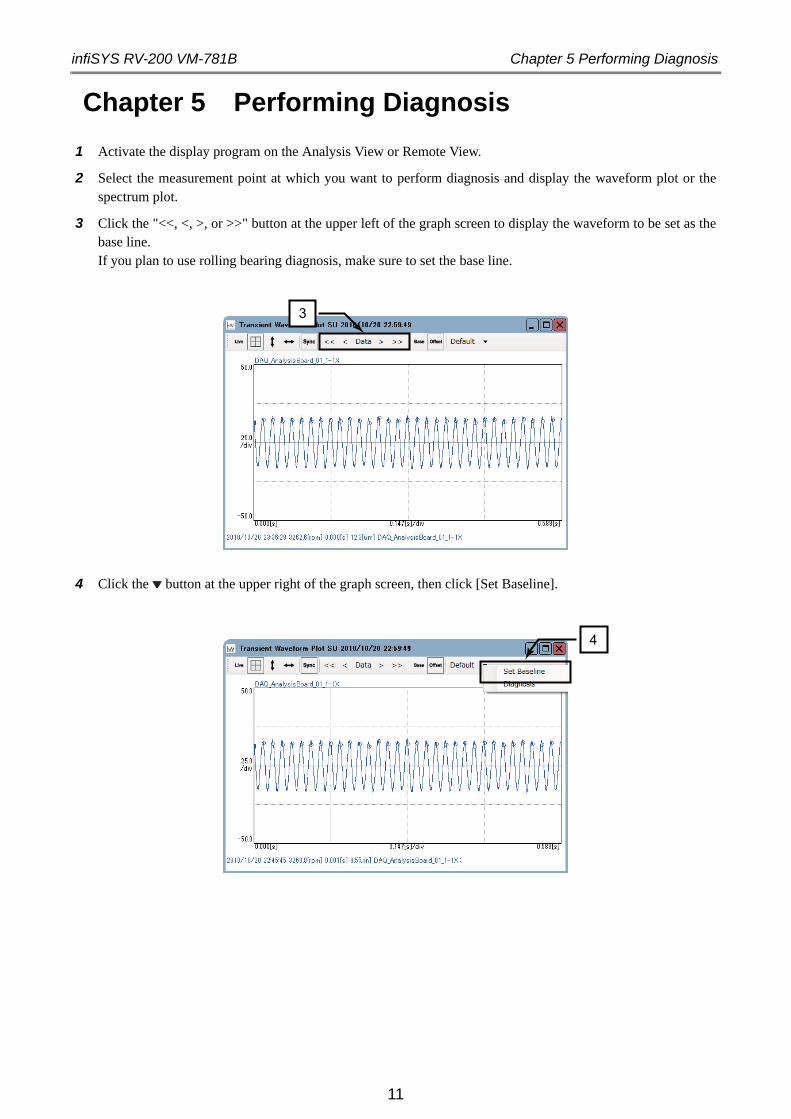
3 Click the "<<, <, >, or >>" button at the upper left of the graph screen to display the waveform to be set as the base line.If you plan to use rolling bearing diagnosis, make sure to set the base line.
4 Click the button at the upper right of the graph screen, then click [Set Baseline].
3
4
11
infiSYS RV-200 VM-781B Chapter 5 Performing Diagnosis
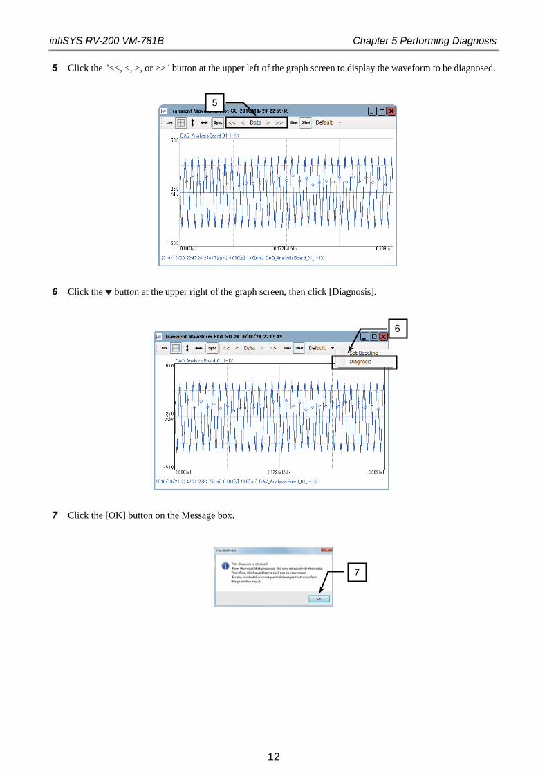
5 Click the "<<, <, >, or >>" button at the upper left of the graph screen to display the waveform to be diagnosed.
6 Click the button at the upper right of the graph screen, then click [Diagnosis].
7 Click the [OK] button on the Message box.
5
6
7
12
infiSYS RV-200 VM-781B Chapter 5 Performing Diagnosis
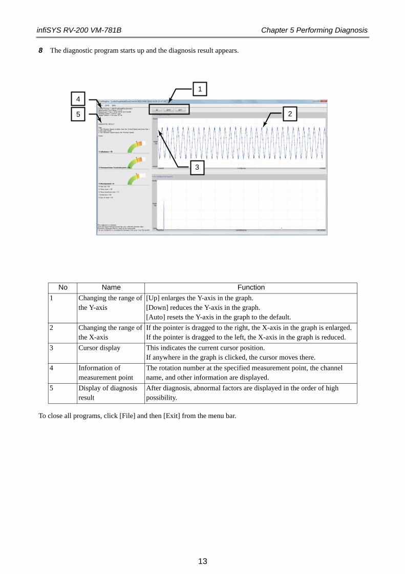
8 The diagnostic program starts up and the diagnosis result appears.
To close all programs, click [File] and then [Exit] from the menu bar.
No Name Function
1 Changing the range of the Y-axis
[Up] enlarges the Y-axis in the graph.[Down] reduces the Y-axis in the graph.[Auto] resets the Y-axis in the graph to the default.
2 Changing the range of the X-axis
If the pointer is dragged to the right, the X-axis in the graph is enlarged.If the pointer is dragged to the left, the X-axis in the graph is reduced.
3 Cursor display This indicates the current cursor position.If anywhere in the graph is clicked, the cursor moves there.
4 Information of measurement point
The rotation number at the specified measurement point, the channel name, and other information are displayed.
5 Display of diagnosis result
After diagnosis, abnormal factors are displayed in the order of high possibility.
2
1
3
5
4
13
infiSYS RV-200 VM-781B Chapter 6 Trouble Shooting
14
Chapter 6 Trouble Shooting
6.1 Trouble Shooting List
If any problems should occur while using the infiSYS RV-200 system, use the table below to solve them. If the table does not help, please contact the nearest Shinkawa Electric Company’s sales office.
Problem Possible Cause Solution
Message "Cannot Get Rated Rotational Speed" appears.
Rated rpm has not been setup. See "4.5 Setting the Machine Information P.10" and setup the rated rpm.
Message "Resonance Frequency is not set" appears and diagnosis stops.
Resonance frequency has not been setup.
See "4.5 Setting the Machine Information P.10" and setup the resonance frequency.
infiSYS RV-200 VM-781B Warranty Policy
15
Warranty Policy
Warranty for this product is provided as follows:
1. Warranty Conditions for Newly Delivered Goods
The warranty period for the goods shall be of three years as from the date of dispatch from our factory (one year for special products and software).If any breakdown/failure occurs to the goods we delivered to you within the said warranty period and if we are responsible for it, we will replace/repair the delivered goods at our factory on our expense.If we have to send an engineer to repair the goods during the warranty period, we ask you to pay the prescribed transportation and the other travel costs. We will bear the costs for the repair in this case.However, we have to remind you that we will not provide any warranty in case of any of the following:
(1)In case of improper handling or use of the goods by the customer(2)In case some other party is responsible for the breakdown/failure(3)In case of alternation or repair performed by any party other than us or any party not authorized by us(4)In case the product is used, handled or stored under such severe environment that is outside of design specifications/conditions(5)In case of a natural disaster or calamity such as fire, flood, earthquake, and lightning strike(6)Consumables(7)Any other breakdown/failure for which we are not considered to be responsible.
Please note that the warranty mentioned above means a warranty just for the delivered goods itself. We will assume no responsibility for the damage, direct or indirect, arising out of the breakdown/failure of the delivered goods.Please also note that, regardless of these clauses above, the warranty period and warranty conditions for any machine/equipment manufactured by manufacturers other than us should be of the responsibility of such other manufacturers.
2. Warranty Conditions for the Repaired Goods
The warranty period for the repaired goods shall be of 6 months after the repair is made, applicable to the parts repaired.Other conditions shall be the same as described in Section 1 above.


4-22 Yoshikawa-Kogyodanchi, Higashihiroshima
739-0153, Japan
Phone : 81-82-429-1118 Fax : 81-82-429-0804
[Service Division] E-mail : [email protected]
Hiroshima Factory


![CICADA - USENIX · 1 vm 2 vm 3 vm 4 vm 5vm 6 vm 7 vm 8 vm 9 vm 2 vm 3 vm 4 vm 5 vm 6 vm 7 vm 8 vm 9 vm 1 rigid application (similar to VOC [1]) vm 1 vm 2 vm 3 vm 4 vm 5vm 6 vm 7 vm](https://img.pdfslide.us/doc/110x75/5f3ade2be7477529602b0cb3/cicada-usenix-1-vm-2-vm-3-vm-4-vm-5vm-6-vm-7-vm-8-vm-9-vm-2-vm-3-vm-4-vm-5-vm.jpg)