Embed Size (px)
Citation preview

Issue 9/16
Page 1
Infinity
BA122 Base Fix and
BA124 Side FixGlass Balustrade Systems
Manual
Issue 9/16
Page 2
MFG Infinity BA122 and BA124 Glass Balustrade Systems
Note 3
Note 4
MFG Systems building code compliance documentation
requires all balustrade installations are to be completed in accordance with their requirements.
The Dulux powder coating warranty period is conditional upon the Balustrade being maintained in accordance with the
Dulux ‘Care and Maintenance Instructions’. See Page 5 for warnings concerning Coastal conditions.
Contact your balustrade installer for a copy of the Care and Maintenance procedure.
Note 2
Index
Code Type of Occupancy for part of the building or structure
Specific Uses Glass
A Domestic and Residential activities
All areas within or serving exclusively one dwelling including stairs, landings etc, but excluding external balconiesand edges of roofs. (see C3)
Residential,12mm Toughened Glass
B, E Offices and work areas not included elsewhere including
storage areas.
Light access stairs and gangways not more than 600mm wideFixed platforms, walkways, stairways and ladders for access
Areas not susceptible to overcrowding in office and institutional buildings; also industrial and storage building.
Commercial,15mm Toughened Glass,
A Other, C3
Areas without obstacles for moving people and not
susceptible to over crowding
Stairs, landings, external balconies, edges of roofs etc. Residential,12mm Toughened Glass
Commercial,15mm Toughened Glass
For 12mm and 15mm Toughened Glass as applicable.
Glass must have a minimum strength of 100MPa. All edges polishedNote 1
Complies With AS/NZS 1170:2002, NZS 4223.3.2016, NZBC B1, B2, F2, F4 and the FOSP Act 1987
MFG Infinity BA122 and BA124 Balustrades are for Domestic and Residential Occupancy types A, A Other and C3 and for Commercial Occupancy Types B, E, A Other and C3
Occupancy Types as per AS/NZ 1170.1.2002. Not suitable for Commercial C1/C2, C5 and D applications
All Frameless glass balustrades must have an Interlinking Rail to conform to NZS 4223.3.2016
Heading Pages Description
All Sections Below for BA 124 Side Fix only
Configurations 3 - 5 Shows typical layouts for Residential 12mm Toughened and Commercial 15mm Toughened Glass
Top Rail 6 Show Interlinking Rail and Typical layout all conforming to NZS 4223.3.2016
General 7 Shows Infinity Clamp Cross section
Components 8 - 10 Shows all Components and Extrusions
Mountings 11 - 20 Shows Mounting details - All Side fixed. To Timber, Concrete and Steel
Installation 21 15 step Recommended Installation guide.
All Sections below for BA 122 Base Fix only
Configurations 22 - 23 Shows typical layouts for Residential 12mm Toughened and Commercial 15mm Toughened Glass
Top Rail 24 Show Interlinking Rail and Typical layout all conforming to NZS 4223.3.2016
General 25 Shows Infinity Clamp Cross section
Components 26 - 27 Shows all Components and Extrusions
Mountings 28 - 30 Shows Mounting details - All Base fixed. To Timber, Concrete and Steel
General Care
Surface Care 31 - 32 Instructions for the care of Powder coated and Glass surfaces.
Issue 9/16
Page 3
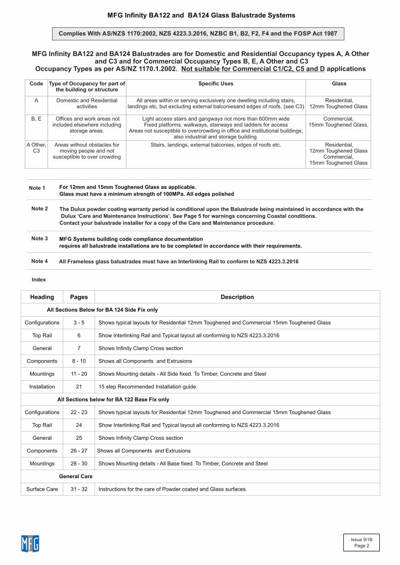
2 x Infinity Glass Clampsper Panel. Side Fix
MFG Infinity Balustradefor Domestic and Residential Occupancytypes A, A Other and C3 only
All for 12mm toughened Glass.Glass must have a minimum strength of 100MPaAll edges polished
3 x Infinity Glass Clampsper Panel. Side Fix
4 x Infinity Glass Clampsper Panel. Side Fix
Residential, 12mm glass
All for 12mm toughened Glass.Glass must have a minimum strength of 100MPaAll edges polished
All for 12mm toughened Glass.Glass must have a minimum strength of 100MPaAll edges polished
Residential, 12mm glass
Residential, 12mm glass
MFG Infinity Balustradefor Domestic and Residential Occupancytypes A, A Other and C3 only
MFG Infinity Balustradefor Domestic and Residential Occupancytypes A, A Other and C3 only
MFG Infinity BA124 Side Fix Glass Balustrade System
Typical Layouts - Residential, 12mm Toughened Glass only
Infinity Glass ClampsTimber Deck Height Options
10
‘Normal’ height say10mm below Deck
Clamp flushwith Deck
Clamp belowDeck
25
Height Height
Height
75+5,-5
75+5,-5
75+5,-5
The 15mm Spacer isrecommended forTimber deck installations
500
500
500
500
500
500
250mm overhangat ends
250mm overhangat ends
Interlinking Top Rail
250mm overhangat ends
Interlinking Top Rail
Interlinking Top Rail
1000mm max width
Balustrade heightabove Clamp1200mm (max)
2000mm max width
Balustrade heightabove Clamp1200mm (max)
Balustrade heightabove Clamp1200mm (max)
1500mm max width
Exceeds the wind loading for all Wind Zonesup to and Including Very High Wind Zone as set out in NZS 3604:2011
Refer to the Interlinking Top Rail page for conformance to NZS 4223.3.2016
Exceeds the wind loading for all Wind Zonesup to and Including Very High Wind Zone as set out in NZS 3604:2011
Refer to the Interlinking Top Rail page for conformance to NZS 4223.3.2016
Exceeds the wind loading for all Wind Zonesup to and Including Very High Wind Zone as set out in NZS 3604:2011
Refer to the Interlinking Top Rail page for conformance to NZS 4223.3.2016
Issue 9/16
Page 4
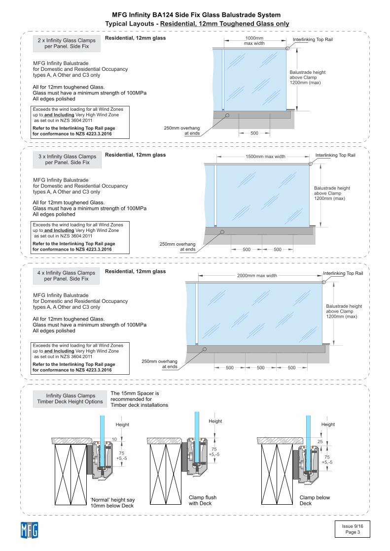
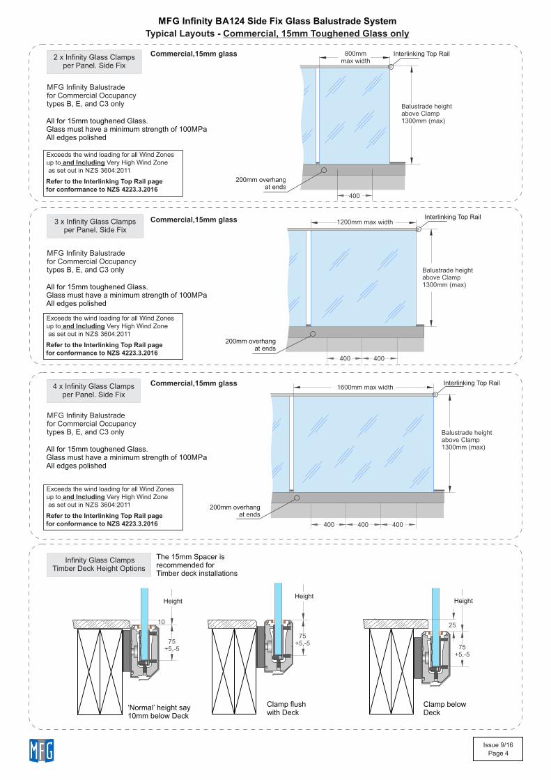
2 x Infinity Glass Clampsper Panel. Side Fix
MFG Infinity Balustradefor Commercial Occupancytypes B, E, and C3 only
All for 15mm toughened Glass.Glass must have a minimum strength of 100MPaAll edges polished
3 x Infinity Glass Clampsper Panel. Side Fix
4 x Infinity Glass Clampsper Panel. Side Fix
Commercial,15mm glass
MFG Infinity Balustradefor Commercial Occupancytypes B, E, and C3 only
All for 15mm toughened Glass.Glass must have a minimum strength of 100MPaAll edges polished
Commercial,15mm glass
MFG Infinity Balustradefor Commercial Occupancytypes B, E, and C3 only
All for 15mm toughened Glass.Glass must have a minimum strength of 100MPaAll edges polished
Commercial,15mm glass
MFG Infinity BA124 Side Fix Glass Balustrade System
Typical Layouts - Commercial, 15mm Toughened Glass only
Infinity Glass ClampsTimber Deck Height Options
10
‘Normal’ height say10mm below Deck
Clamp flushwith Deck
Clamp belowDeck
25
Height Height
Height
75+5,-5
75+5,-5
75+5,-5
The 15mm Spacer isrecommended forTimber deck installations
400
400
400
400
400
400
200mm overhangat ends
200mm overhangat ends
200mm overhangat ends
Interlinking Top Rail
Interlinking Top Rail
Interlinking Top Rail
Exceeds the wind loading for all Wind Zonesup to and Including Very High Wind Zone as set out in NZS 3604:2011
Refer to the Interlinking Top Rail page for conformance to NZS 4223.3.2016
Exceeds the wind loading for all Wind Zonesup to and Including Very High Wind Zone as set out in NZS 3604:2011
Refer to the Interlinking Top Rail page for conformance to NZS 4223.3.2016
Exceeds the wind loading for all Wind Zonesup to and Including Very High Wind Zone as set out in NZS 3604:2011
Refer to the Interlinking Top Rail page for conformance to NZS 4223.3.2016
Balustrade heightabove Clamp1300mm (max)
Balustrade heightabove Clamp1300mm (max)
800mm max width
1200mm max width
1600mm max width
Balustrade heightabove Clamp1300mm (max)
Issue 9/16
Page 5
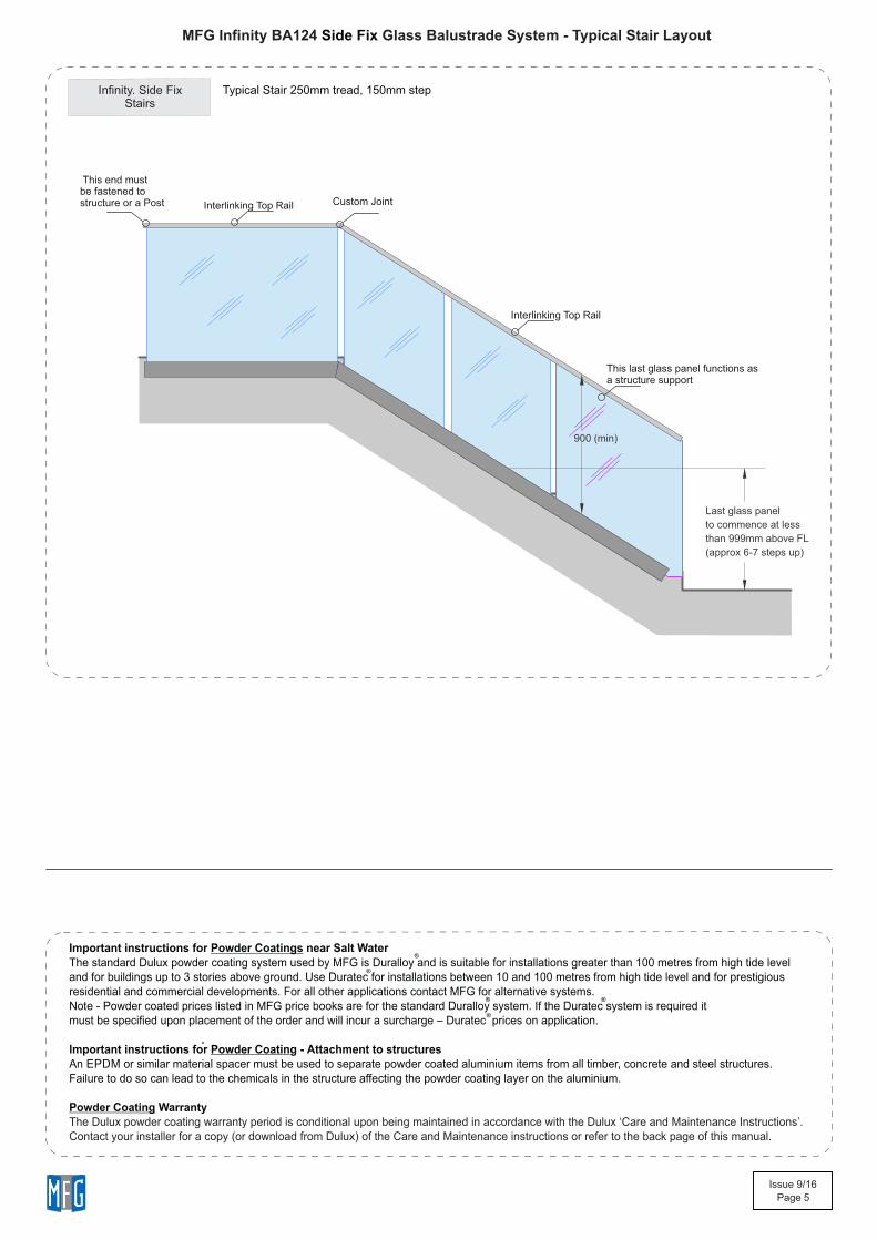
MFG Infinity BA124 Glass Balustrade System - Typical Stair LayoutSide Fix
Infinity. Side FixStairs
Typical Stair 250mm tread, 150mm step
This last glass panel functions asa structure support
Last glass panel
to commence at less
than 999mm above FL
(approx 6-7 steps up)
900 (min)
Custom Joint Interlinking Top Rail
Interlinking Top Rail
This end mustbe fastened tostructure or a Post
Important instructions for Powder Coatings near Salt WaterThe standard Dulux powder coating system used by MFG is Duralloy and is suitable for installations greater than 100 metres from high tide leveland for buildings up to 3 stories above ground. Use Duratec for installations between 10 and 100 metres from high tide level and for prestigious residential and commercial developments. For all other applications contact MFG for alternative systems.Note - Powder coated prices listed in MFG price books are for the standard Duralloy system. If the Duratec system is required it must be specified upon placement of the order and will incur a surcharge – Duratec prices on application.
lmportant instructions for Powder Coating - Attachment to structuresAn EPDM or similar material spacer must be used to separate powder coated aluminium items from all timber, concrete and steel structures.Failure to do so can lead to the chemicals in the structure affecting the powder coating layer on the aluminium.
Powder Coating WarrantyThe Dulux powder coating warranty period is conditional upon being maintained in accordance with the Dulux ‘Care and Maintenance Instructions’.Contact your installer for a copy (or download from Dulux) of the Care and Maintenance instructions or refer to the back page of this manual.
®
®
®
®
®

Issue 9/16
Page 6
MFG Infinity BA124 Glass Balustrade System Side Fix Interlinking Top Rail conforming to NZS 4223.3.2016 and Building Code Clause B1.3.4
38
30
22.1
22.2
Interlinking Top Rail Extrusion for 12 and 15mm Toughened Glass
Interlinking Top Rail End Cap38.4x30.4mm
Toughened Glass
V60 SiliconeJoining Top Rail,Wedge and Glass
Interlinking Top Rail Gasket(12mm version shown)
Interlinking Top Rail Gasketsfor 12 and 15mm Toughened Glass(12mm version shown)
Application Notes:- Cut short lengths of Gasket (50mm) and place say every 700mm.- Cut/adjust Interlinking rail to correct dimensions, test in place.- Remove all, install full cut lengths of Gasket to glass top edge
- Assemble Top Rail + Joiners and suitable End plates
- Place blobs of V60 silicone in every Gasket hole- Then place Top Rail extrusion + Joiners and End plates in place clipping firmly to Gasket- Tape all down, wait 24 hrs to fully bond. Clean up.
Note: Ends must be attached to structure or post, - Joins must have a suitable joiner plate
Holes for Silicone
Interlinking Top RailEnd Plate, SS. 100x45mm
Interlinking Top Rail Corner Joiner75x75x5mm
Interlinking Top RailStraight Joiner 80x22.8x5mm
Interlinking Top RailEnd Plate, SS. 120x45mm
Interlinking Top RailEnd Plate, SS. 120x45mm
Interlinking Top RailEnd Plate, SS. 100x65mm
Tabs all 22.5 x 4mm SS. Front faces all 3mm SS
Joiners both 22.5 x 5mm Aluminium
Joiners: (After cutting extrusions to length)- With Joiner in place, spot drill from below for position- Drill out to joiner to 3mm dia, extrusion to 4mm dia- Use No 6 x 1/4in SS ST Pan sq drive Screw- One end must be attached.- Joins must be within 300mm of Post
Joiners both 22.5 x 5mmAluminium
End Plates: (After cutting extrusions to length)- With End Plate in place, spot drill from below for position- Drill out to SS tab to 3mm dia, extrusion to 4mm dia- Use No 6 x 1/4in SS ST Pan sq drive Screw- End Plate must be securely attached to Post or structure.
End PlateTabs all 22.5 x 4mm SS.
-
Issue 9/16
Page 7
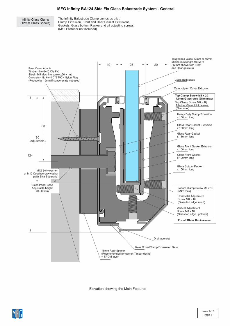
MFG Infinity BA124 Side Fix Glass Balustrade System - General
Infinity Glass Clamp(12mm Glass Shown)
The Infinity Balustrade Clamp comes as a kit;Clamp Extrusion, Front and Rear Gasket ExtrusionsGaskets, Glass bottom Packer and all adjusting screws.(M12 Fastener not included)
Elevation showing the Main Features
124
19
20
25
60
Toughened Glass 12mm or 15mm Minimum strength 100MPa(12mm shown with Frontand Rear gaskets)
Outer clip on Cover Extrusion
Heavy Duty Clamp Extrusionx 150mm long
Bottom Clamp Screw M8 x 16(5Nm max)
Horizontal Adjustment Screw M8 x 16(Glass top edge in/out)
Vertical Adjustment Screw M8 x 16(Glass top edge up/down)
Drainage slot
Rear Cover/Clamp Extrusuion Base
15mm Rear Spacer(Recommended for use on Timber decks)+ EPDM layer
Glass Rear Gasket Extrusionx 150mm long
Glass Front Gasket Extrusionx 100mm long
Glass Bulb seals
80(adjustable)
Glass Front Gasket x 100mm long
Rear Cover AttachTimber - No 6x40 C/s PKSteel - M5 Machine screw x50 + nutConcrete - No 6x40 C/S PK + Nylon Plug(Reduce by 15mm if spacer plate not used)
Glass Rear Gasketx 150mm long
Glass Bottom Packerx 150mm longM12 Bolt+washer,
or M12 Coachscrew+washer(with Sika Supergrip)
Glass Panel BaseAdjustable height
70 - 80mm
Top Clamp Screw M8 x 20 12mm Glass only (5Nm max)
Top Clamp Screw M8 x 16 All other Glass thicknesses (5Nm max)
For all Glass thicknesses
Issue 9/16
Page 8
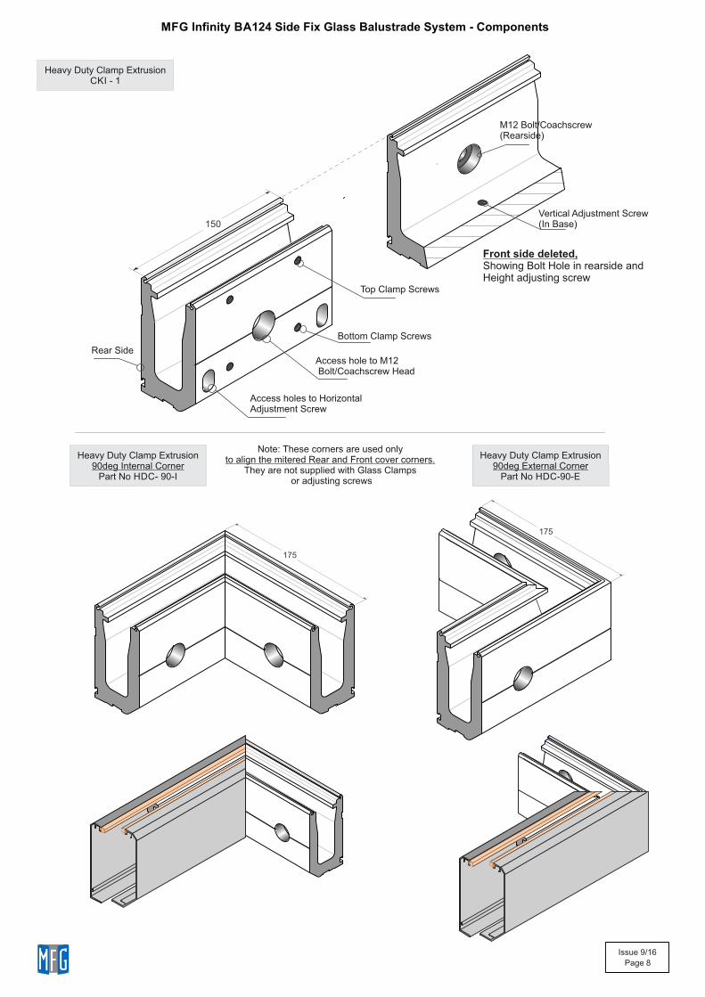
MFG Infinity BA124 Side Fix Glass Balustrade System - Components
Heavy Duty Clamp Extrusion90deg Internal Corner
Part No HDC- 90-I
Heavy Duty Clamp Extrusion90deg External Corner
Part No HDC-90-E
Bottom Clamp Screws
Access hole to M12 Bolt/Coachscrew Head
150
Access holes to HorizontalAdjustment Screw
M12 Bolt/Coachscrew(Rearside)
Vertical Adjustment Screw(In Base)
Front side deleted,Showing Bolt Hole in rearside andHeight adjusting screw
Rear Side
Top Clamp Screws
175
175
Note: These corners are used onlyto align the mitered Rear and Front cover corners.
They are not supplied with Glass Clamps or adjusting screws
Heavy Duty Clamp ExtrusionCKI - 1
Issue 9/16
Page 9
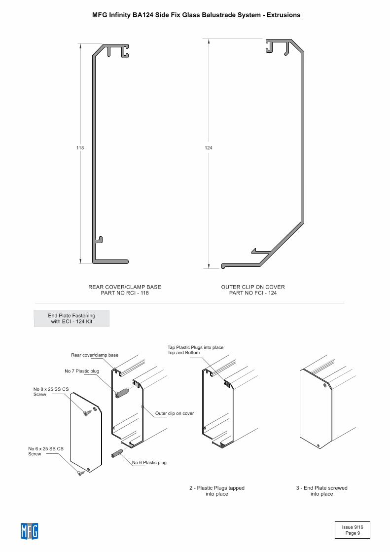
OUTER CLIP ON COVERPART NO FCI - 124
REAR COVER/CLAMP BASE PART NO RCI - 118
118
124
End Plate Fasteningwith ECI - 124 Kit
No 6 Plastic plug
Tap Plastic Plugs into placeTop and Bottom
No 8 x 25 SS CSScrew
No 6 x 25 SS CSScrew
2 - Plastic Plugs tappedinto place
3 - End Plate screwedinto place
Rear cover/clamp base
Outer clip on cover
No 7 Plastic plug
MFG Infinity BA124 Side Fix Glass Balustrade System - Extrusions
Issue 9/16
Page 10
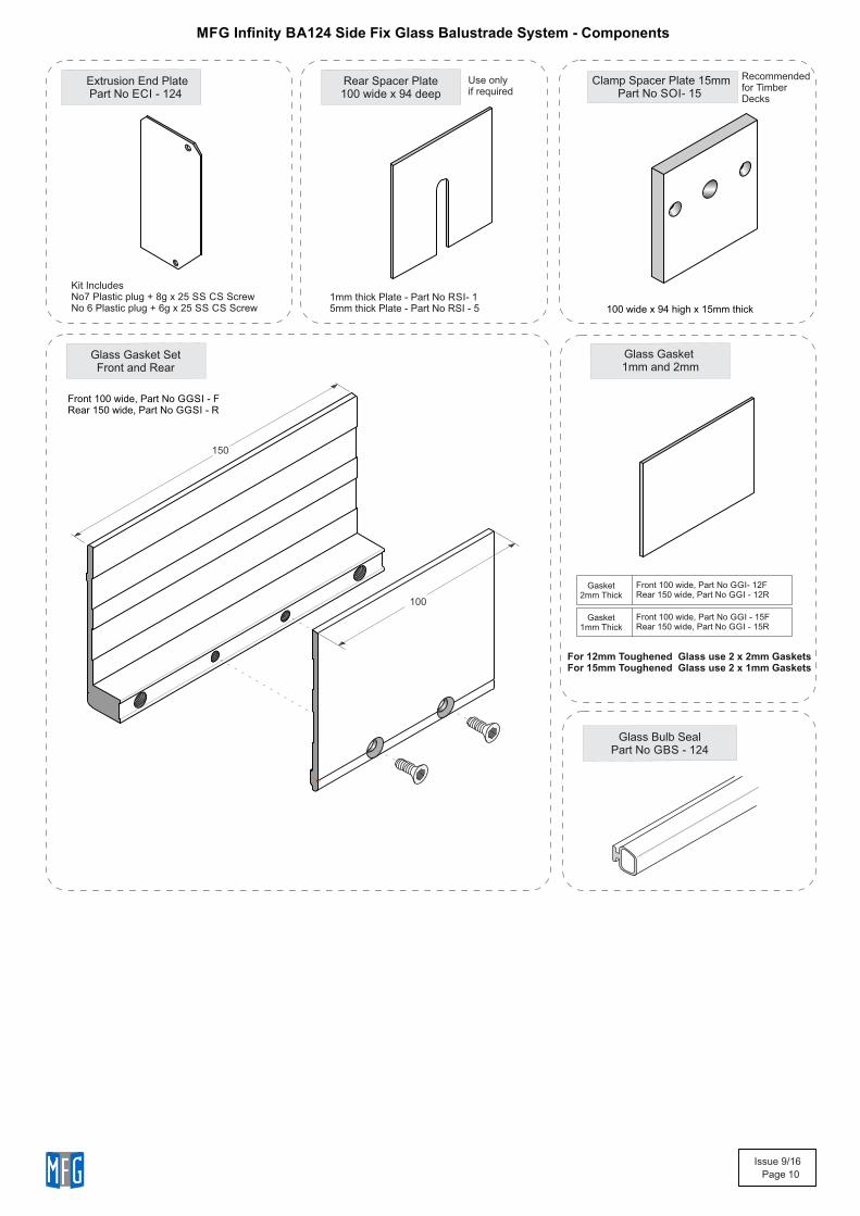
Extrusion End PlatePart No ECI - 124
Glass Gasket SetFront and Rear
Rear Spacer Plate100 wide x 94 deep
Clamp Spacer Plate 15mmPart No SOI- 15
Glass Gasket 1mm and 2mm
100 wide x 94 high x 15mm thick
Front 100 wide, Part No GGI- 12F Rear 150 wide, Part No GGI - 12R
150
100
Glass Bulb SealPart No GBS - 124
Gasket
2mm Thick
Front 100 wide, Part No GGI - 15F Rear 150 wide, Part No GGI - 15R
Gasket
1mm Thick
Kit IncludesNo7 Plastic plug + 8g x 25 SS CS ScrewNo 6 Plastic plug + 6g x 25 SS CS Screw
Use onlyif required
MFG Infinity BA124 Side Fix Glass Balustrade System - Components
Front 100 wide, Part No GGSI - F Rear 150 wide, Part No GGSI - R
Recommendedfor TimberDecks
1mm thick Plate - Part No RSI- 15mm thick Plate - Part No RSI - 5
For 12mm Toughened Glass use 2 x 2mm Gaskets For 15mm Toughened Glass use 2 x 1mm Gaskets
Issue 9/16
Page 11
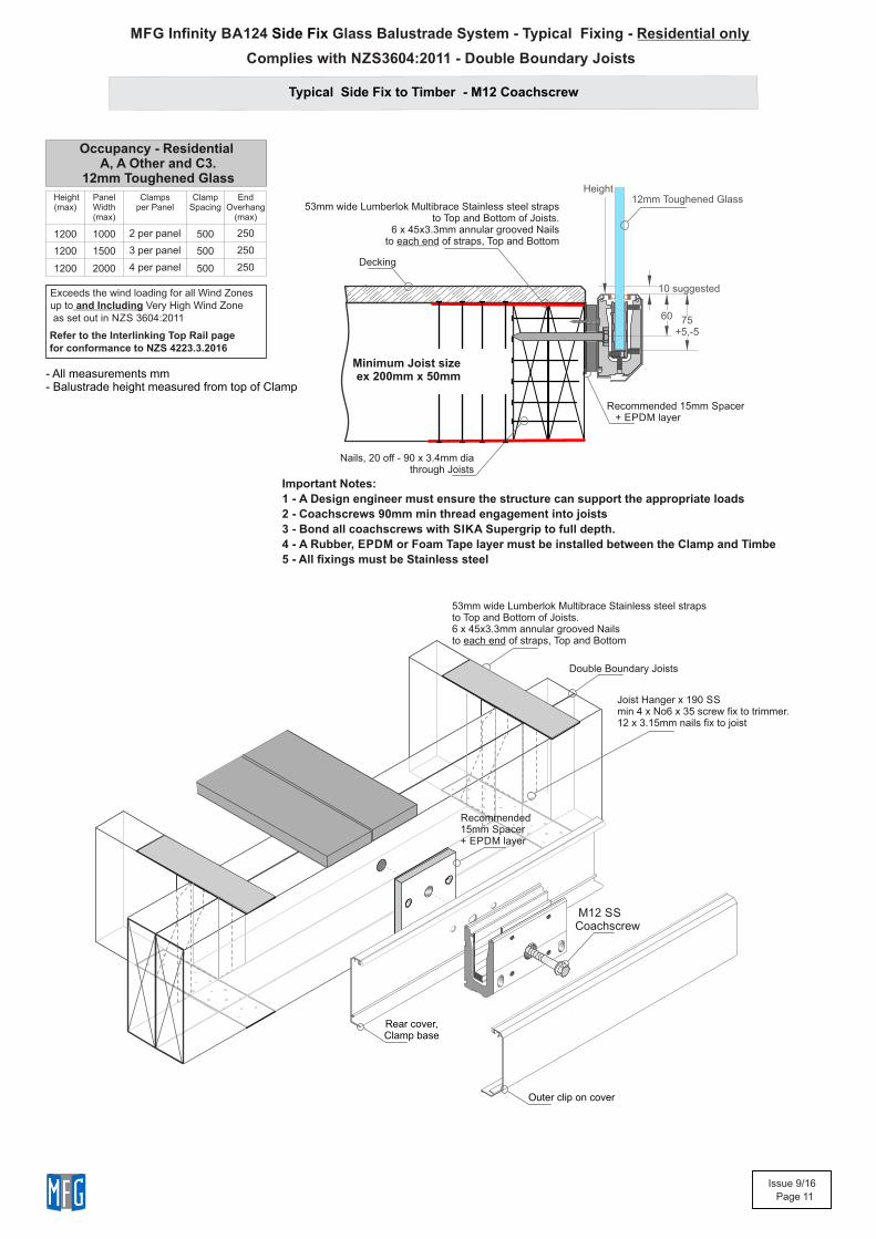
MFG Infinity BA124 Glass Balustrade System - Typical Fixing - Residential onlySide Fix
Typical Side Fix to Timber - M12 Coachscrew
Joist Hanger x 190 SS min 4 x No6 x 35 screw fix to trimmer.12 x 3.15mm nails fix to joist
Double Boundary Joists
Minimum Joist sizeex 200mm x 50mm
60
Nails, 20 off - 90 x 3.4mm dia through Joists
Decking
53mm wide Lumberlok Multibrace Stainless steel strapsto Top and Bottom of Joists.
6 x 45x3.3mm annular grooved Nailsto each end of straps, Top and Bottom
Outer clip on cover
Rear cover,Clamp base
10 suggested
Occupancy - Residential A, A Other and C3.
12mm Toughened Glass
53mm wide Lumberlok Multibrace Stainless steel strapsto Top and Bottom of Joists. 6 x 45x3.3mm annular grooved Nailsto each end of straps, Top and Bottom
12mm Toughened Glass
75+5,-5
Height(max)
Panel Width (max)
Clampsper Panel
Clamp Spacing
End Overhang
(max)
1200 1000 2 per panel 500 250
1200 1500 3 per panel 500 250
1200 2000 4 per panel 500 250
Height
Recommended 15mm Spacer + EPDM layer
M12 SS Coachscrew
Recommended 15mm Spacer + EPDM layer
Important Notes:
1 - s A Design engineer must ensure the structure can support the appropriate load
2 - Coachscrews 90mm min thread engagement into joists
3 - Bond all coachscrews with SIKA Supergrip to full depth.
4 - A Rubber, EPDM or Foam Tape layer must be installed between the Clamp and Timbe
5 - All fixings must be Stainless steel
Exceeds the wind loading for all Wind Zonesup to and Including Very High Wind Zone as set out in NZS 3604:2011
Refer to the Interlinking Top Rail page for conformance to NZS 4223.3.2016
- All measurements mm- Balustrade height measured from top of Clamp
Complies with NZS3604:2011 - Double Boundary Joists
Issue 9/16
Page 12
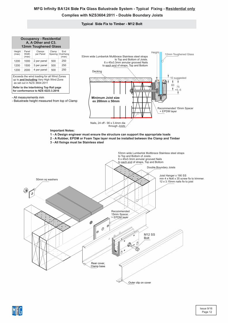
Typical Side Fix to Timber - M12 Bolt
MFG Infinity BA124 Glass Balustrade System - Typical Fixing - Residential onlySide Fix
50mm sq washers
Minimum Joist sizeex 200mm x 50mm
Decking
Nails, 24 off - 90 x 3.4mm dia through Joists
60
Joist Hanger x 190 SS min 4 x No6 x 35 screw fix to trimmer.12 x 3.15mm nails fix to joist
Double Boundary Joists
10 suggested
53mm wide Lumberlok Multibrace Stainless steel strapsto Top and Bottom of Joists.
6 x 45x3.3mm annular grooved Nailsto each end of straps, Top and Bottom
53mm wide Lumberlok Multibrace Stainless steel strapsto Top and Bottom of Joists. 6 x 45x3.3mm annular grooved Nailsto each end of straps, Top and Bottom
75+5,-5
Height
Outer clip on cover
Rear cover,Clamp base
M12 SS Bolt
Recommended 15mm Spacer + EPDM layer
Recommended 15mm Spacer + EPDM layer
Occupancy - Residential A, A Other and C3.
12mm Toughened Glass
Height(max)
Panel Width (max)
Clampsper Panel
Clamp Spacing
End Overhang
(max)
1200 1000 2 per panel 500 250
1200 1500 3 per panel 500 250
1200 2000 4 per panel 500 250
12mm Toughened Glass
Important Notes:
1 - s A Design engineer must ensure the structure can support the appropriate load
2 - A Rubber, EPDM or Foam Tape layer must be installed between the Clamp and Timber
3 - All fixings must be Stainless steel
Exceeds the wind loading for all Wind Zonesup to and Including Very High Wind Zone as set out in NZS 3604:2011
Refer to the Interlinking Top Rail page for conformance to NZS 4223.3.2016
- All measurements mm- Balustrade height measured from top of Clamp
Complies with NZS3604:2011 - Double Boundary Joists
Issue 9/16
Page 13
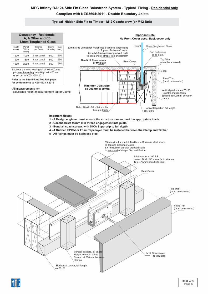
MFG Infinity BA124 Glass Balustrade System - Typical Fixing - Residential onlySide Fix
Typical Hidden Side Fix to Timber - M12 Coachscrew (or M12 Bolt)
Joist Hanger x 190 SS min 4 x No6 x 35 screw fix to trimmer.12 x 3.15mm nails fix to joist
Minimum Joist sizeex 200mm x 50mm
Nails, 20 off - 90 x 3.4mm dia through Joists
Rear Cover
53mm wide Lumberlok Multibrace Stainless steel strapsto Top and Bottom of Joists.
6 x 45x3.3mm annular grooved Nailsto each end of straps, Top and Bottom
5 gap
53mm wide Lumberlok Multibrace Stainless steel strapsto Top and Bottom of Joists. 6 x 45x3.3mm annular grooved Nailsto each end of straps, Top and Bottom
Horizontal packer, full lengthex 75x50
Vertical packers, ex 75x50Height to match JoistsSpaced at 500mm, betweenclamps
Top Trim(must be screwed)
Front Trim(must be screwed)
Important Note.
No Front Cover used, Back cover only
Use M12 Coachscrew or M12 Bolt
Vertical packers, ex 75x50Height to match JoistsSpaced at 500mm, betweenclamps
Top Trim(must be screwed)
Front Trim(must be screwed)
M12 Coachscrew or M12 Bolt
Gap both sidesto be 5mm
Height(max)
Panel Width (max)
Clampsper Panel
Clamp Spacing
Overhang
1200 1000 2 per panel 500 250
1200 1500 3 per panel 500 250
1200 2000 4 per panel 500 250
Rear Cover
Horizontal packer, full lengthex 75x50
Height 12mm Toughened Glass
Important Notes:
1 - s A Design engineer must ensure the structure can support the appropriate load
2 - Coachscrews 90mm min thread engagement into joists
3 - Bond all coachscrews with SIKA Supergrip to full depth.
4 - A Rubber, EPDM or Foam Tape layer must be installed between the Clamp and Timber
5 - All fixings must be Stainless steel
Occupancy - Residential A, A Other and C3.
12mm Toughened Glass
Exceeds the wind loading for all Wind Zonesup to and Including Very High Wind Zone as set out in NZS 3604:2011
Refer to the Interlinking Top Rail page for conformance to NZS 4223.3.2016
- All measurements mm- Balustrade height measured from top of Clamp
Complies with NZS3604:2011 - Double Boundary Joists
Issue 9/16
Page 14
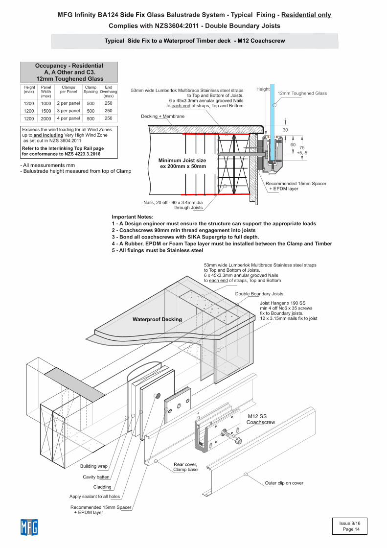
MFG Infinity BA124 Glass Balustrade System - Typical Fixing - Residential onlySide Fix
Typical Side Fix to a Waterproof Timber deck - M12 Coachscrew
Minimum Joist sizeex 200mm x 50mm
60
Nails, 20 off - 90 x 3.4mm dia through Joists
Decking + Membrane
30
53mm wide Lumberlok Multibrace Stainless steel strapsto Top and Bottom of Joists.
6 x 45x3.3mm annular grooved Nailsto each end of straps, Top and Bottom
53mm wide Lumberlok Multibrace Stainless steel strapsto Top and Bottom of Joists. 6 x 45x3.3mm annular grooved Nailsto each end of straps, Top and Bottom
Double Boundary Joists
Waterproof Decking
Building wrap
Cavity batten
Cladding
Apply sealant to all holes
Joist Hanger x 190 SS min 4 off No6 x 35 screwsfix to Boundary joists.12 x 3.15mm nails fix to joist
Outer clip on cover
Rear cover,Clamp base
75+5,-5
Height
M12 SS Coachscrew
Recommended 15mm Spacer + EPDM layer
Recommended 15mm Spacer + EPDM layer
Occupancy - Residential A, A Other and C3.
12mm Toughened Glass
Height(max)
Panel Width (max)
Clampsper Panel
Clamp Spacing
End Overhang
(max)
1200 1000 2 per panel 500 250
1200 1500 3 per panel 500 250
1200 2000 4 per panel 500 250
12mm Toughened Glass
Important Notes:
1 - s A Design engineer must ensure the structure can support the appropriate load
2 - Coachscrews 90mm min thread engagement into joists
3 - Bond all coachscrews with SIKA Supergrip to full depth.
4 - A Rubber, EPDM or Foam Tape layer must be installed between the Clamp and Timber
5 - All fixings must be Stainless steel
Exceeds the wind loading for all Wind Zonesup to and Including Very High Wind Zone as set out in NZS 3604:2011
Refer to the Interlinking Top Rail page for conformance to NZS 4223.3.2016
- All measurements mm- Balustrade height measured from top of Clamp
Complies with NZS3604:2011 - Double Boundary Joists
Issue 9/16
Page 15
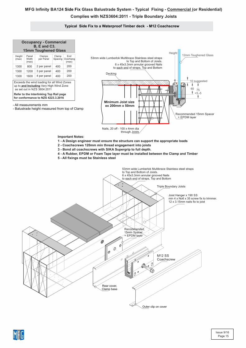
MFG Infinity BA124 Glass Balustrade System - Typical Fixing - Commercial (or Residential)Side Fix
Typical Side Fix to a Waterproof Timber deck - M12 Coachscrew
Joist Hanger x 190 SS min 4 x No6 x 35 screw fix to trimmer.12 x 3.15mm nails fix to joist
53mm wide Lumberlok Multibrace Stainless steel strapsto Top and Bottom of Joists. 6 x 45x3.3mm annular grooved Nailsto each end of straps, Top and Bottom
Triple Boundary Joists
Height(max)
Panel Width (max)
Clampsper Panel
Clamp Spacing
End Overhang
(max)
1300 800 2 per panel 400 200
1300 1200 3 per panel 400 200
1300 1600 4 per panel 400 200
Outer clip on cover
Rear cover,Clamp base
M12 SS Coachscrew
Recommended 15mm Spacer + EPDM layer
Nails, 20 off - 100 x 4mm dia through Joists
Minimum Joist sizeex 200mm x 50mm
60
Decking
53mm wide Lumberlok Multibrace Stainless steel strapsto Top and Bottom of Joists.
6 x 45x3.3mm annular grooved Nailsto each end of straps, Top and Bottom
10 suggested
75+5,-5
Height
Recommended 15mm Spacer + EPDM layer
Occupancy - Commercial B, E and C3.
15mm Toughened Glass12mm Toughened Glass
Important Notes:
1 - s A Design engineer must ensure the structure can support the appropriate load
2 - Coachscrews 120mm min thread engagement into joists
3 - Bond all coachscrews with SIKA Supergrip to full depth.
4 - A Rubber, EPDM or Foam Tape layer must be installed between the Clamp and Timber
5 - All fixings must be Stainless steel
Exceeds the wind loading for all Wind Zonesup to and Including Very High Wind Zone as set out in NZS 3604:2011
Refer to the Interlinking Top Rail page for conformance to NZS 4223.3.2016
- All measurements mm- Balustrade height measured from top of Clamp
Complies with NZS3604:2011 - Triple Boundary Joists
Issue 9/16
Page 16
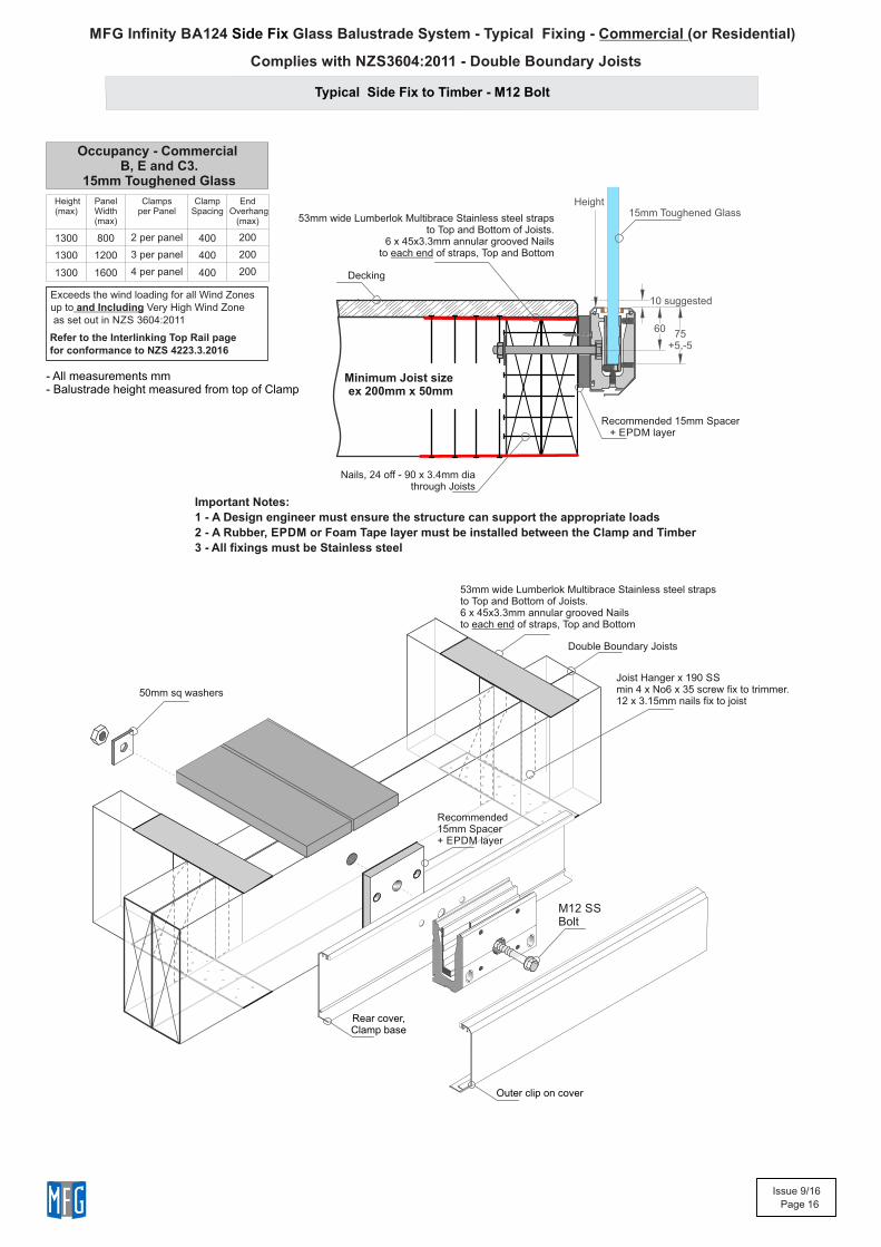
MFG Infinity BA124 Glass Balustrade System - Typical Fixing - Commercial (or Residential)Side Fix
Typical Side Fix to Timber - M12 Bolt
Joist Hanger x 190 SS min 4 x No6 x 35 screw fix to trimmer.12 x 3.15mm nails fix to joist
Double Boundary Joists
50mm sq washers
Minimum Joist sizeex 200mm x 50mm
Decking
Nails, 24 off - 90 x 3.4mm dia through Joists
60
10 suggested
53mm wide Lumberlok Multibrace Stainless steel strapsto Top and Bottom of Joists.
6 x 45x3.3mm annular grooved Nailsto each end of straps, Top and Bottom
53mm wide Lumberlok Multibrace Stainless steel strapsto Top and Bottom of Joists. 6 x 45x3.3mm annular grooved Nailsto each end of straps, Top and Bottom
75+5,-5
Height
M12 SS Bolt
Outer clip on cover
Rear cover,Clamp base
Recommended 15mm Spacer + EPDM layer
Recommended 15mm Spacer + EPDM layer
Height(max)
Panel Width (max)
Clampsper Panel
Clamp Spacing
End Overhang
(max)
1300 800 2 per panel 400 200
1300 1200 3 per panel 400 200
1300 1600 4 per panel 400 200
Occupancy - Commercial B, E and C3.
15mm Toughened Glass
15mm Toughened Glass
Important Notes:
1 - s A Design engineer must ensure the structure can support the appropriate load
2 - A Rubber, EPDM or Foam Tape layer must be installed between the Clamp and Timber
3 - All fixings must be Stainless steel
Exceeds the wind loading for all Wind Zonesup to and Including Very High Wind Zone as set out in NZS 3604:2011
Refer to the Interlinking Top Rail page for conformance to NZS 4223.3.2016
- All measurements mm- Balustrade height measured from top of Clamp
Complies with NZS3604:2011 - Double Boundary Joists
Issue 9/16
Page 17
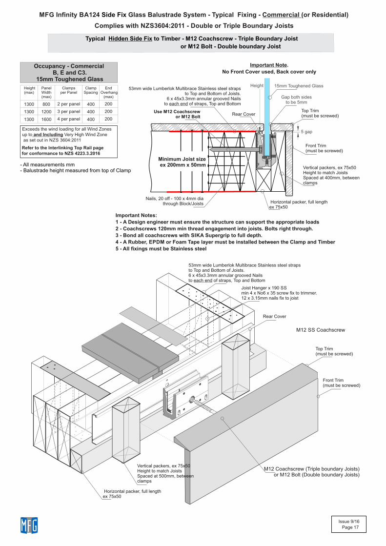
MFG Infinity BA124 Glass Balustrade System - Typical Fixing - Commercial (or Residential)Side Fix
Typical Hidden Side Fix to Timber - M12 Coachscrew - Triple Boundary Joist
or M12 Bolt - Double boundary Joist
Minimum Joist sizeex 200mm x 50mm
53mm wide Lumberlok Multibrace Stainless steel strapsto Top and Bottom of Joists.
6 x 45x3.3mm annular grooved Nailsto each end of straps, Top and Bottom
5 gap
Vertical packers, ex 75x50Height to match JoistsSpaced at 400mm, betweenclamps
Front Trim(must be screwed)
Use M12 Coachscrew or M12 Bolt
Joist Hanger x 190 SS min 4 x No6 x 35 screw fix to trimmer.12 x 3.15mm nails fix to joist
M12 SS Coachscrew
53mm wide Lumberlok Multibrace Stainless steel strapsto Top and Bottom of Joists. 6 x 45x3.3mm annular grooved Nailsto each end of straps, Top and Bottom
Horizontal packer, full lengthex 75x50
Top Trim(must be screwed)
Front Trim(must be screwed)
Vertical packers, ex 75x50Height to match JoistsSpaced at 500mm, betweenclamps
Nails, 20 off - 100 x 4mm dia through Block/Joists
Top Trim(must be screwed)
Gap both sidesto be 5mm
Important Note.
No Front Cover used, Back cover only
Rear Cover
Horizontal packer, full lengthex 75x50
Rear Cover
M12 Coachscrew (Triple boundary Joists) or M12 Bolt (Double boundary Joists)
Height Height(max)
Panel Width (max)
Clampsper Panel
Clamp Spacing
End Overhang
(max)
1300 800 2 per panel 400 200
1300 1200 3 per panel 400 200
1300 1600 4 per panel 400 200
Occupancy - Commercial B, E and C3.
15mm Toughened Glass15mm Toughened Glass
Important Notes:
1 - s A Design engineer must ensure the structure can support the appropriate load
2 - Coachscrews 120mm min thread engagement into joists. Bolts right through.
3 - Bond all coachscrews with SIKA Supergrip to full depth.
4 - A Rubber, EPDM or Foam Tape layer must be installed between the Clamp and Timber
5 - All fixings must be Stainless steel
Exceeds the wind loading for all Wind Zonesup to and Including Very High Wind Zone as set out in NZS 3604:2011
Refer to the Interlinking Top Rail page for conformance to NZS 4223.3.2016
- All measurements mm- Balustrade height measured from top of Clamp
Complies with NZS3604:2011 - Double or Triple Boundary Joists
Issue 9/16
Page 18
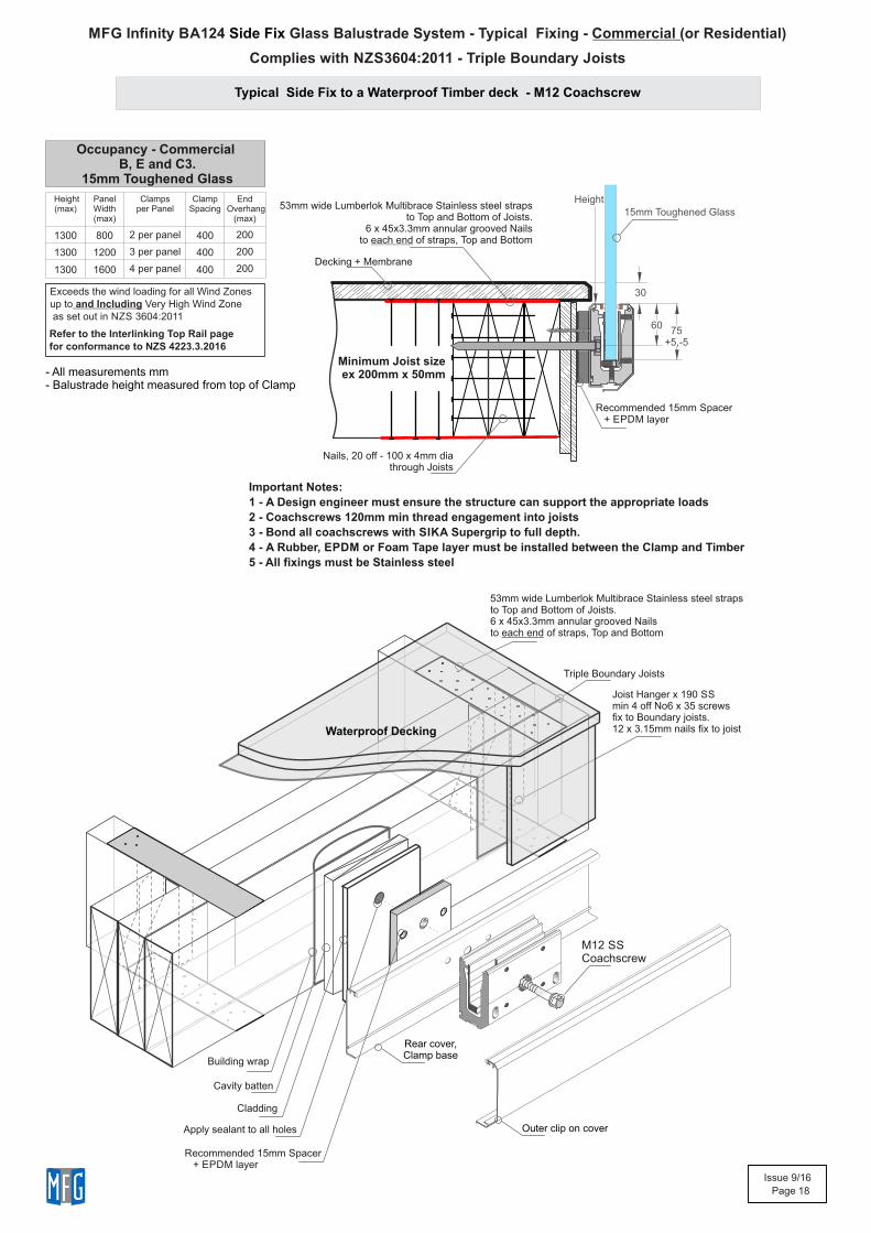
MFG Infinity BA124 Glass Balustrade System - Typical Fixing - Commercial (or Residential)Side Fix
Typical Side Fix to a Waterproof Timber deck - M12 Coachscrew
60
30
Minimum Joist sizeex 200mm x 50mm
Nails, 20 off - 100 x 4mm dia through Joists
Decking + Membrane
53mm wide Lumberlok Multibrace Stainless steel strapsto Top and Bottom of Joists.
6 x 45x3.3mm annular grooved Nailsto each end of straps, Top and Bottom
53mm wide Lumberlok Multibrace Stainless steel strapsto Top and Bottom of Joists. 6 x 45x3.3mm annular grooved Nailsto each end of straps, Top and Bottom
Triple Boundary Joists
Waterproof Decking
Building wrap
Cavity batten
Cladding
Apply sealant to all holes
Joist Hanger x 190 SS min 4 off No6 x 35 screwsfix to Boundary joists.12 x 3.15mm nails fix to joist
M12 SS Coachscrew
Rear cover,Clamp base
75+5,-5
Height
Outer clip on cover
Recommended 15mm Spacer + EPDM layer
Recommended 15mm Spacer + EPDM layer
Height(max)
Panel Width (max)
Clampsper Panel
Clamp Spacing
End Overhang
(max)
1300 800 2 per panel 400 200
1300 1200 3 per panel 400 200
1300 1600 4 per panel 400 200
Occupancy - Commercial B, E and C3.
15mm Toughened Glass
15mm Toughened Glass
Important Notes:
1 - s A Design engineer must ensure the structure can support the appropriate load
2 - Coachscrews 120mm min thread engagement into joists
3 - Bond all coachscrews with SIKA Supergrip to full depth.
4 - A Rubber, EPDM or Foam Tape layer must be installed between the Clamp and Timber
5 - All fixings must be Stainless steel
Exceeds the wind loading for all Wind Zonesup to and Including Very High Wind Zone as set out in NZS 3604:2011
Refer to the Interlinking Top Rail page for conformance to NZS 4223.3.2016
- All measurements mm- Balustrade height measured from top of Clamp
Complies with NZS3604:2011 - Triple Boundary Joists
Issue 9/16
Page 19
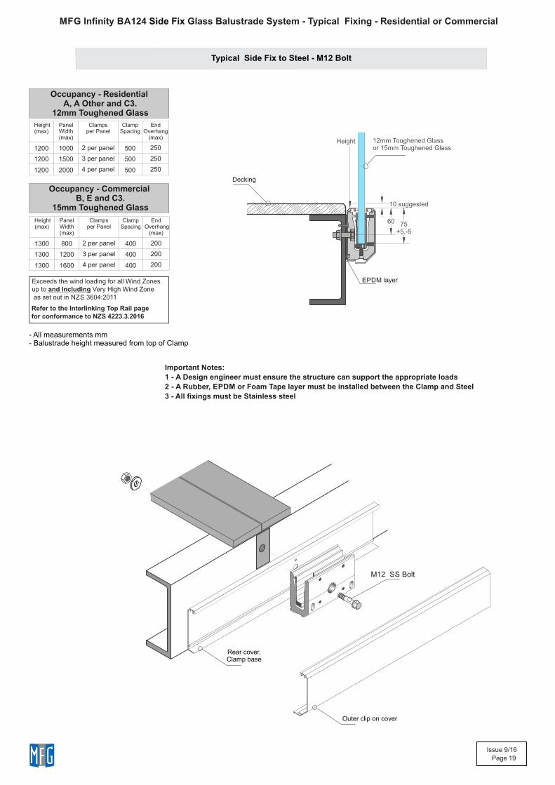
MFG Infinity BA124 Glass Balustrade System - Typical Fixing - Residential or Commercial Side Fix
Typical Side Fix to Steel - M12 Bolt
Decking
60
10 suggested
Outer clip on cover
Rear cover,Clamp base
M12 SS Bolt
EPDM layer
75+5,-5
Height
Occupancy - Residential A, A Other and C3.
12mm Toughened Glass
Height(max)
Panel Width (max)
Clampsper Panel
Clamp Spacing
End Overhang
(max)
1200 1000 2 per panel 500 250
1200 1500 3 per panel 500 250
1200 2000 4 per panel 500 250
Height(max)
Panel Width (max)
Clampsper Panel
Clamp Spacing
End Overhang
(max)
1300 800 2 per panel 400 200
1300 1200 3 per panel 400 200
1300 1600 4 per panel 400 200
Occupancy - Commercial B, E and C3.
15mm Toughened Glass
12mm Toughened Glassor 15mm Toughened Glass
Important Notes:
1 - s A Design engineer must ensure the structure can support the appropriate load
2 - A Rubber, EPDM or Foam Tape layer must be installed between the Clamp and Steel
3 - All fixings must be Stainless steel
Exceeds the wind loading for all Wind Zonesup to and Including Very High Wind Zone as set out in NZS 3604:2011
Refer to the Interlinking Top Rail page for conformance to NZS 4223.3.2016
- All measurements mm- Balustrade height measured from top of Clamp
Issue 9/16
Page 20
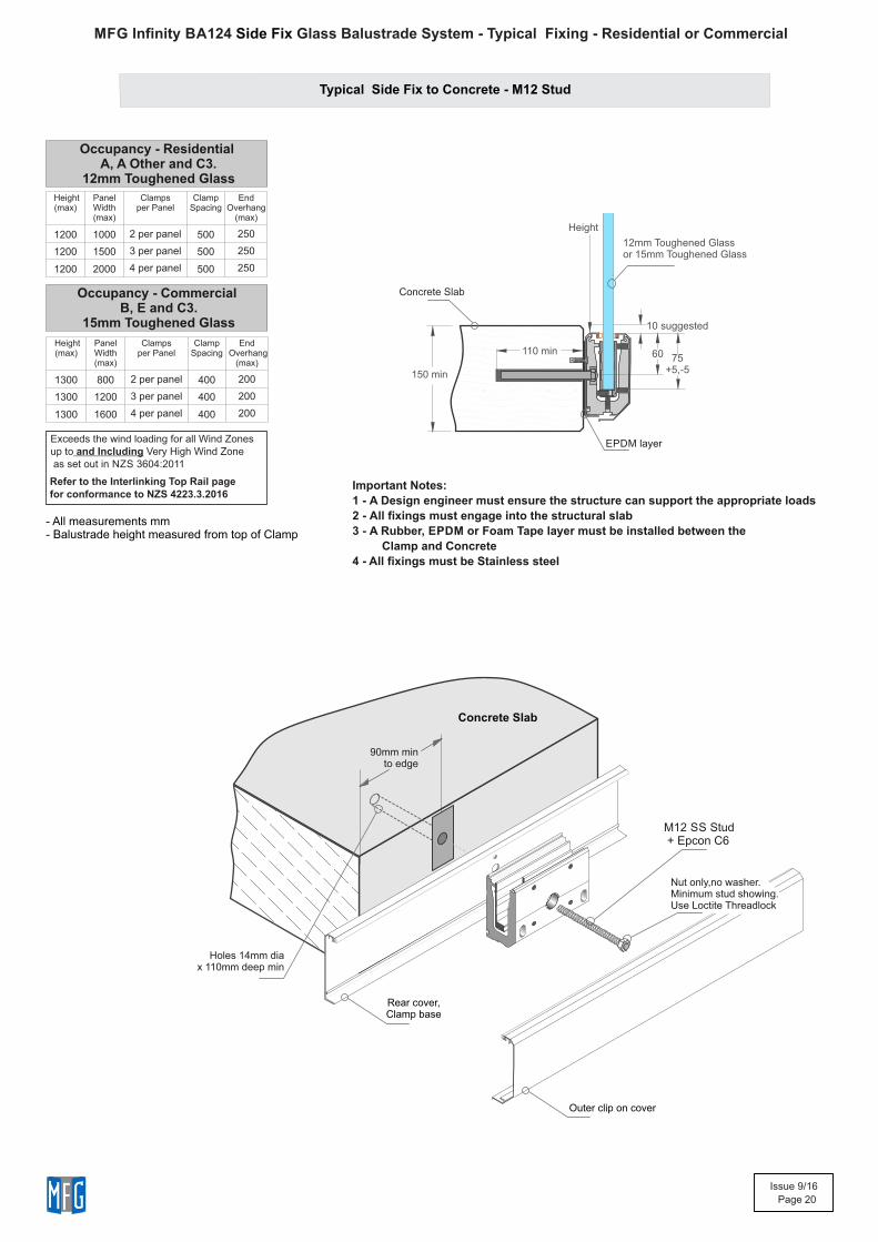
MFG Infinity BA124 Glass Balustrade System - Typical Fixing - Residential or Commercial Side Fix
Typical Side Fix to Concrete - M12 Stud
Concrete Slab
Holes 14mm dia x 110mm deep min
90mm min to edge
150 min
110 min
Concrete Slab
60
Outer clip on cover
Rear cover,Clamp base
M12 SS Stud + Epcon C6
10 suggested
EPDM layer
75+5,-5
Height
Nut only,no washer.Minimum stud showing.Use Loctite Threadlock
Occupancy - Residential A, A Other and C3.
12mm Toughened Glass
Height(max)
Panel Width (max)
Clampsper Panel
Clamp Spacing
End Overhang
(max)
1200 1000 2 per panel 500 250
1200 1500 3 per panel 500 250
1200 2000 4 per panel 500 250
Height(max)
Panel Width (max)
Clampsper Panel
Clamp Spacing
End Overhang
(max)
1300 800 2 per panel 400 200
1300 1200 3 per panel 400 200
1300 1600 4 per panel 400 200
Occupancy - Commercial B, E and C3.
15mm Toughened Glass
12mm Toughened Glassor 15mm Toughened Glass
Important Notes:
1 - s A Design engineer must ensure the structure can support the appropriate load
2 - All fixings must engage into the structural slab
3 - A Rubber, EPDM or Foam Tape layer must be installed between the
Clamp and Concrete
4 - All fixings must be Stainless steel
Exceeds the wind loading for all Wind Zonesup to and Including Very High Wind Zone as set out in NZS 3604:2011
Refer to the Interlinking Top Rail page for conformance to NZS 4223.3.2016
- All measurements mm- Balustrade height measured from top of Clamp
Issue 9/16
Page 21
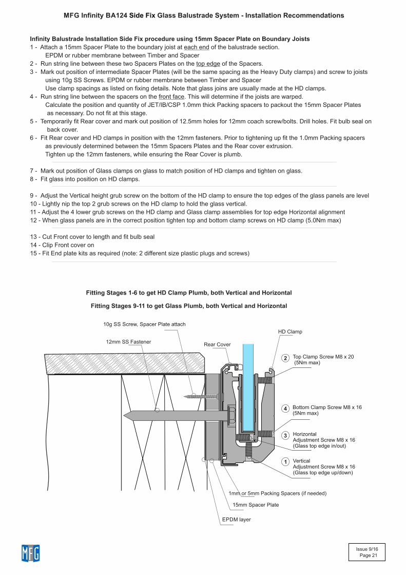
Infinity Balustrade Installation Side Fix procedure using 15mm Spacer Plate on Boundary Joists
1 - Attach a 15mm Spacer Plate to the boundary joist at each end of the balustrade section.
EPDM or rubber membrane between Timber and Spacer
2 - Run string line between these two Spacers Plates on the top edge of the Spacers.
3 - Mark out position of intermediate Spacer Plates (will be the same spacing as the Heavy Duty clamps) and screw to joists
using 10g SS Screws. EPDM or rubber membrane between Timber and Spacer
Use clamp spacings as listed on fixing details. Note that glass joins are usually made at the HD clamps.
4 - Run string line between the spacers on the front face. This will determine if the joists are warped.
Calculate the position and quantity of JET/IB/CSP 1.0mm thick Packing spacers to packout the 15mm Spacer Plates
as necessary. Do not fit at this stage.
5 - Temporarily fit Rear cover and mark out position of 12.5mm holes for 12mm coach screw/bolts. Drill holes. Fit bulb seal on
back cover.
6 - Fit Rear cover and HD clamps in position with the 12mm fasteners. Prior to tightening up fit the 1.0mm Packing spacers
as previously determined between the 15mm Spacers Plates and the Rear cover extrusion.
Tighten up the 12mm fasteners, while ensuring the Rear Cover is plumb.
7 - Mark out position of Glass clamps on glass to match position of HD clamps and tighten on glass.
8 - Fit glass into position on HD clamps.
9 - Adjust the Vertical height grub screw on the bottom of the HD clamp to ensure the top edges of the glass panels are level
10 - Lightly nip the top 2 grub screws on the HD clamp to hold the glass vertical.
11 - Adjust the 4 lower grub screws on the HD clamp and Glass clamp assemblies for top edge Horizontal alignment
12 - When glass panels are in the correct position tighten top and bottom clamp screws on HD clamp (5.0Nm max)
13 - Cut Front cover to length and fit bulb seal
14 - Clip Front cover on
15 - Fit End plate kits as required (note: 2 different size plastic plugs and screws)
EPDM layer
10g SS Screw, Spacer Plate attach
1mm or 5mm Packing Spacers (if needed)
Rear Cover12mm SS Fastener
HD Clamp
15mm Spacer Plate
Fitting Stages 1-6 to get HD Clamp Plumb, both Vertical and Horizontal
Top Clamp Screw M8 x 20 (5Nm max)
Bottom Clamp Screw M8 x 16(5Nm max)
HorizontalAdjustment Screw M8 x 16(Glass top edge in/out)
VerticalAdjustment Screw M8 x 16(Glass top edge up/down)
1
2
3
4
Fitting Stages 9-11 to get Glass Plumb, both Vertical and Horizontal
MFG Infinity BA124 Glass Balustrade System - Installation RecommendationsSide Fix
Issue 9/16
Page 22
500
500
500
250mm overhangat ends
Interlinking Top Rail1000mm max width
Balustrade heightabove Deck1200mm (max)
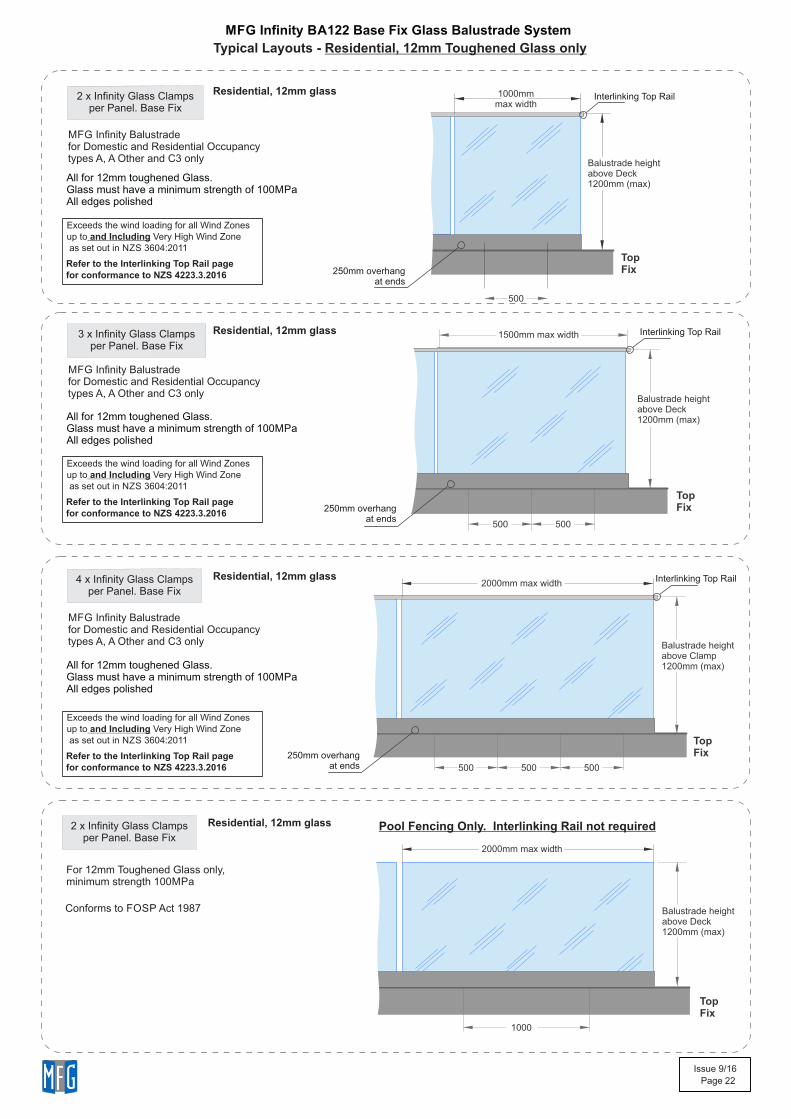
2 x Infinity Glass Clampsper Panel. Base Fix
All for 12mm toughened Glass.Glass must have a minimum strength of 100MPaAll edges polished
3 x Infinity Glass Clampsper Panel. Base Fix
4 x Infinity Glass Clampsper Panel. Base Fix
500
500
500
250mm overhangat ends
Residential, 12mm glass
All for 12mm toughened Glass.Glass must have a minimum strength of 100MPaAll edges polished
All for 12mm toughened Glass.Glass must have a minimum strength of 100MPaAll edges polished
Residential, 12mm glass
Residential, 12mm glass
Exceeds the wind loading for all Wind Zonesup to and Including Very High Wind Zone as set out in NZS 3604:2011
Refer to the Interlinking Top Rail page for conformance to NZS 4223.3.2016
250mm overhangat ends
Interlinking Top Rail
Interlinking Top Rail
Exceeds the wind loading for all Wind Zonesup to and Including Very High Wind Zone as set out in NZS 3604:2011
Refer to the Interlinking Top Rail page for conformance to NZS 4223.3.2016
Exceeds the wind loading for all Wind Zonesup to and Including Very High Wind Zone as set out in NZS 3604:2011
Refer to the Interlinking Top Rail page for conformance to NZS 4223.3.2016
2000mm max width
Balustrade heightabove Deck1200mm (max)
Balustrade heightabove Clamp1200mm (max)
1500mm max width
TopFix
TopFix
TopFix
2 x Infinity Glass Clampsper Panel. Base Fix
1000
Residential, 12mm glass
2000mm max width
Balustrade heightabove Deck1200mm (max)
TopFix
For 12mm Toughened Glass only,minimum strength 100MPa
Conforms to FOSP Act 1987
Pool Fencing Only. Interlinking Rail not required
MFG Infinity BA122 Base Fix Glass Balustrade System
Typical Layouts - Residential, 12mm Toughened Glass only
MFG Infinity Balustradefor Domestic and Residential Occupancytypes A, A Other and C3 only
MFG Infinity Balustradefor Domestic and Residential Occupancytypes A, A Other and C3 only
MFG Infinity Balustradefor Domestic and Residential Occupancytypes A, A Other and C3 only
Issue 9/16
Page 23
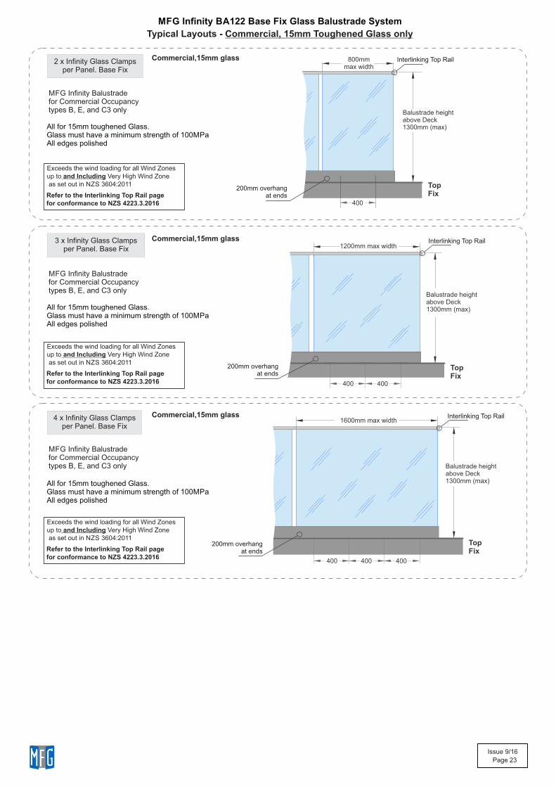
2 x Infinity Glass Clampsper Panel. Base Fix
All for 15mm toughened Glass.Glass must have a minimum strength of 100MPaAll edges polished
3 x Infinity Glass Clampsper Panel. Base Fix
4 x Infinity Glass Clampsper Panel. Base Fix
400
400
400
Commercial,15mm glass
All for 15mm toughened Glass.Glass must have a minimum strength of 100MPaAll edges polished
Commercial,15mm glass
All for 15mm toughened Glass.Glass must have a minimum strength of 100MPaAll edges polished
Commercial,15mm glass
400
400
400
200mm overhangat ends
200mm overhangat ends
200mm overhangat ends
Interlinking Top Rail
Interlinking Top Rail
Interlinking Top Rail
Exceeds the wind loading for all Wind Zonesup to and Including Very High Wind Zone as set out in NZS 3604:2011
Refer to the Interlinking Top Rail page for conformance to NZS 4223.3.2016
Exceeds the wind loading for all Wind Zonesup to and Including Very High Wind Zone as set out in NZS 3604:2011
Refer to the Interlinking Top Rail page for conformance to NZS 4223.3.2016
Exceeds the wind loading for all Wind Zonesup to and Including Very High Wind Zone as set out in NZS 3604:2011
Refer to the Interlinking Top Rail page for conformance to NZS 4223.3.2016
Balustrade heightabove Deck1300mm (max)
Balustrade heightabove Deck1300mm (max)
800mm max width
1200mm max width
1600mm max width
Balustrade heightabove Deck1300mm (max)
TopFix
TopFix
TopFix
MFG Infinity BA122 Base Fix Glass Balustrade System
Typical Layouts - Commercial, 15mm Toughened Glass only
MFG Infinity Balustradefor Commercial Occupancytypes B, E, and C3 only
MFG Infinity Balustradefor Commercial Occupancytypes B, E, and C3 only
MFG Infinity Balustradefor Commercial Occupancytypes B, E, and C3 only
Issue 9/16
Page 24
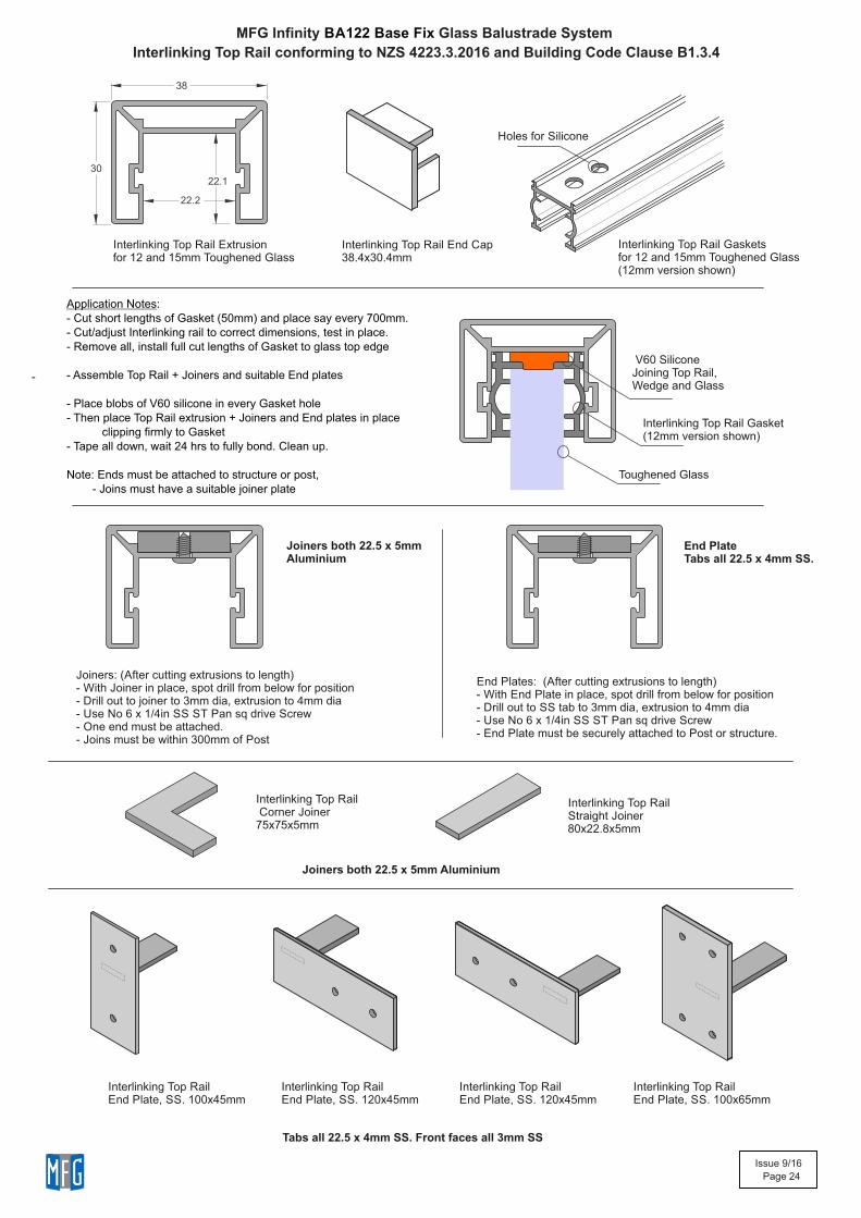
MFG Infinity Glass Balustrade System BA122 Base Fix
Interlinking Top Rail conforming to NZS 4223.3.2016 and Building Code Clause B1.3.4
38
30
22.1
22.2
Interlinking Top Rail Extrusion for 12 and 15mm Toughened Glass
Interlinking Top Rail End Cap38.4x30.4mm
Toughened Glass
V60 SiliconeJoining Top Rail,Wedge and Glass
Interlinking Top Rail Gasket(12mm version shown)
Interlinking Top Rail Gasketsfor 12 and 15mm Toughened Glass(12mm version shown)
Application Notes:- Cut short lengths of Gasket (50mm) and place say every 700mm.- Cut/adjust Interlinking rail to correct dimensions, test in place.- Remove all, install full cut lengths of Gasket to glass top edge
- Assemble Top Rail + Joiners and suitable End plates
- Place blobs of V60 silicone in every Gasket hole- Then place Top Rail extrusion + Joiners and End plates in place clipping firmly to Gasket- Tape all down, wait 24 hrs to fully bond. Clean up.
Note: Ends must be attached to structure or post, - Joins must have a suitable joiner plate
Holes for Silicone
Interlinking Top RailEnd Plate, SS. 100x45mm
Interlinking Top Rail Corner Joiner75x75x5mm
Interlinking Top RailStraight Joiner 80x22.8x5mm
Interlinking Top RailEnd Plate, SS. 120x45mm
Interlinking Top RailEnd Plate, SS. 120x45mm
Interlinking Top RailEnd Plate, SS. 100x65mm
Tabs all 22.5 x 4mm SS. Front faces all 3mm SS
Joiners both 22.5 x 5mm Aluminium
Joiners: (After cutting extrusions to length)- With Joiner in place, spot drill from below for position- Drill out to joiner to 3mm dia, extrusion to 4mm dia- Use No 6 x 1/4in SS ST Pan sq drive Screw- One end must be attached.- Joins must be within 300mm of Post
Joiners both 22.5 x 5mmAluminium
End Plates: (After cutting extrusions to length)- With End Plate in place, spot drill from below for position- Drill out to SS tab to 3mm dia, extrusion to 4mm dia- Use No 6 x 1/4in SS ST Pan sq drive Screw- End Plate must be securely attached to Post or structure.
End PlateTabs all 22.5 x 4mm SS.
-
Issue 9/16
Page 25
Infinity Glass ClampBase Fix
(12mm Glass Shown)
Elevation showing the Main Features
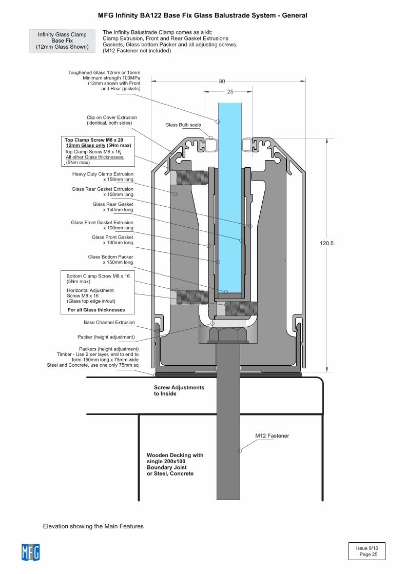
MFG Infinity BA122 Base Fix Glass Balustrade System - General
The Infinity Balustrade Clamp comes as a kit;Clamp Extrusion, Front and Rear Gasket ExtrusionsGaskets, Glass bottom Packer and all adjusting screws.(M12 Fastener not included)
80
25
120.5
Wooden Decking with single 200x100Boundary Joistor Steel, Concrete
Toughened Glass 12mm or 15mm Minimum strength 100MPa
(12mm shown with Frontand Rear gaskets)
Clip on Cover Extrusion(identical, both sides)
Heavy Duty Clamp Extrusionx 150mm long
Bottom Clamp Screw M8 x 16(5Nm max)
Horizontal Adjustment Screw M8 x 16(Glass top edge in/out)
Glass Rear Gasket Extrusionx 150mm long
Glass Front Gasket Extrusionx 100mm long
Glass Bulb seals
Glass Front Gasket x 100mm long
Glass Rear Gasketx 150mm long
Glass Bottom Packerx 150mm long
Top Clamp Screw M8 x 20 12mm Glass only (5Nm max)
Top Clamp Screw M8 x 16 All other Glass thicknesses (5Nm max)
For all Glass thicknesses
Packers (height adjustment)Timber - Use 2 per layer, end to end to
form 150mm long x 75mm wideSteel and Concrete, use one only 75mm sq
Base Channel Extrusion
Packer (height adjustment)
M12 Fastener
Screw Adjustmentsto Inside
Issue 9/16
Page 26
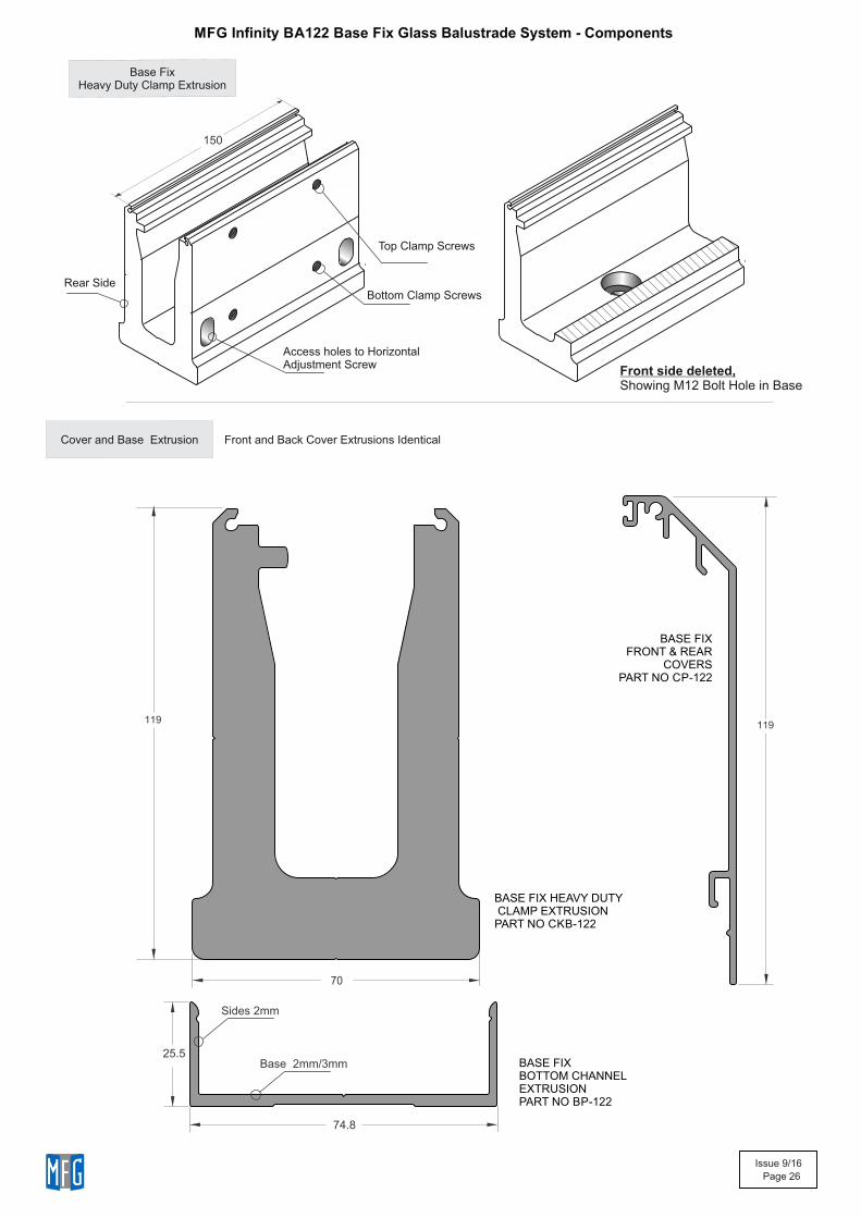
Bottom Clamp Screws
150
Access holes to HorizontalAdjustment Screw
Front side deleted,Showing M12 Bolt Hole in Base
Rear Side
Top Clamp Screws
Cover and Base Extrusion Front and Back Cover Extrusions Identical
119
25.5
74.8
Sides 2mm
Base 2mm/3mm
70
119
BASE FIX BOTTOM CHANNELEXTRUSIONPART NO BP-122
BASE FIX FRONT & REAR
COVERSPART NO CP-122
BASE FIX HEAVY DUTY CLAMP EXTRUSIONPART NO CKB-122
Base FixHeavy Duty Clamp Extrusion
MFG Infinity BA122 Base Fix Glass Balustrade System - Components
Issue 9/16
Page 27
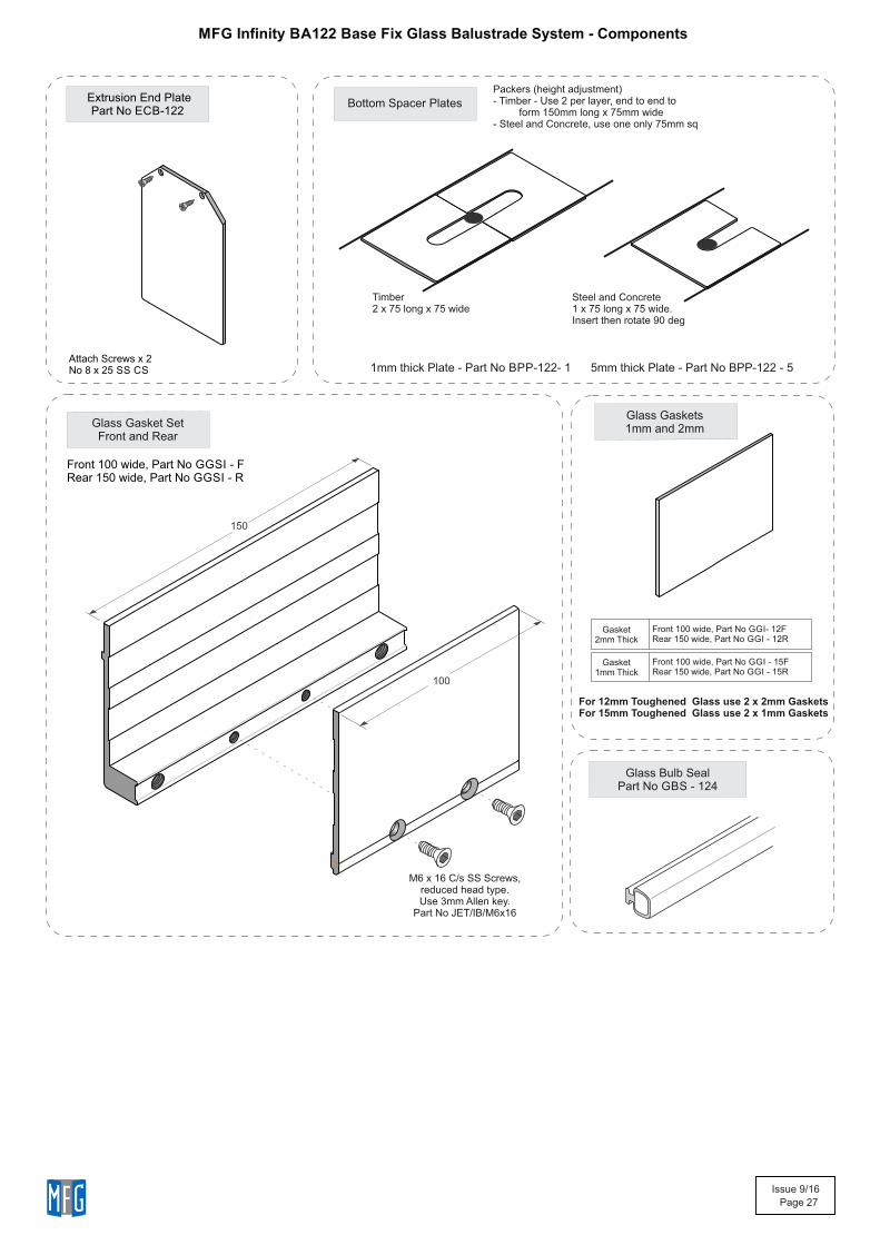
Extrusion End PlatePart No ECB-122
Bottom Spacer Plates
Timber2 x 75 long x 75 wide
Glass Gasket SetFront and Rear
Glass Gaskets1mm and 2mm
150
100
For 12mm Toughened Glass use 2 x 2mm Gaskets For 15mm Toughened Glass use 2 x 1mm Gaskets
M6 x 16 C/s SS Screws,reduced head type.Use 3mm Allen key.
Part No JET/IB/M6x16
Attach Screws x 2 No 8 x 25 SS CS
Packers (height adjustment)- Timber - Use 2 per layer, end to end to form 150mm long x 75mm wide- Steel and Concrete, use one only 75mm sq
Steel and Concrete1 x 75 long x 75 wide.Insert then rotate 90 deg
MFG Infinity BA122 Base Fix Glass Balustrade System - Components
1mm thick Plate - Part No BPP-122- 1 5mm thick Plate - Part No BPP-122 - 5
Front 100 wide, Part No GGSI - F Rear 150 wide, Part No GGSI - R
Front 100 wide, Part No GGI- 12F Rear 150 wide, Part No GGI - 12R
Gasket
2mm Thick
Front 100 wide, Part No GGI - 15F Rear 150 wide, Part No GGI - 15R
Gasket
1mm Thick
Glass Bulb SealPart No GBS - 124
Issue 9/16
Page 28
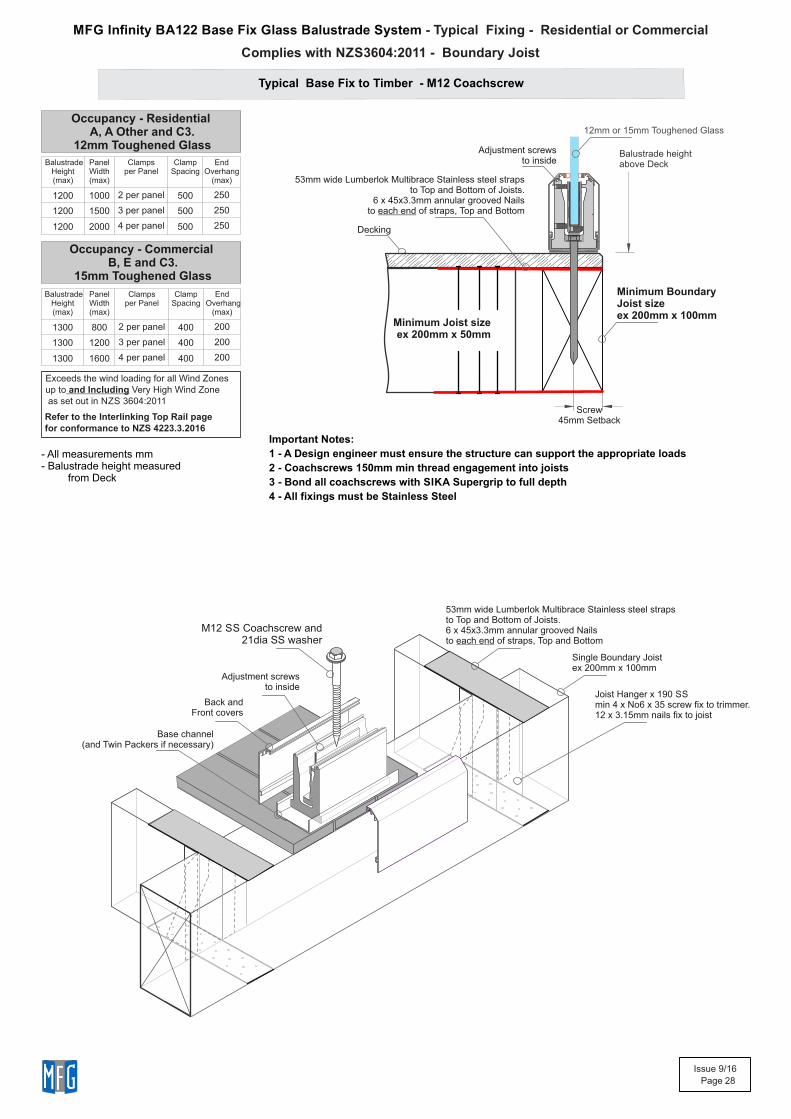
Typical Base Fix to Timber - M12 Coachscrew
- Typical Fixing - Residential or CommercialMFG Infinity BA122 Base Fix Glass Balustrade System
Joist Hanger x 190 SS min 4 x No6 x 35 screw fix to trimmer.12 x 3.15mm nails fix to joist
53mm wide Lumberlok Multibrace Stainless steel strapsto Top and Bottom of Joists. 6 x 45x3.3mm annular grooved Nailsto each end of straps, Top and Bottom
Decking
53mm wide Lumberlok Multibrace Stainless steel strapsto Top and Bottom of Joists.
6 x 45x3.3mm annular grooved Nailsto each end of straps, Top and Bottom
Minimum Joist sizeex 200mm x 50mm
Important Notes:
1 - A Design engineer must ensure the structure can support the appropriate loads
2 - Coachscrews 150mm min thread engagement into joists
3 - Bond all coachscrews with SIKA Supergrip to full depth
4 - All fixings must be Stainless Steel
12mm or 15mm Toughened Glass
Balustrade heightabove Deck
Screw45mm Setback
Balustrade Height(max)
Panel Width (max)
Clampsper Panel
Clamp Spacing
End Overhang
(max)
1300 800 2 per panel 400 200
1300 1200 3 per panel 400 200
1300 1600 4 per panel 400 200
Occupancy - Commercial B, E and C3.
15mm Toughened Glass
Occupancy - Residential A, A Other and C3.
12mm Toughened Glass
Balustrade Height(max)
Panel Width (max)
Clampsper Panel
Clamp Spacing
End Overhang
(max)
1200 1000 2 per panel 500 250
1200 1500 3 per panel 500 250
1200 2000 4 per panel 500 250
Exceeds the wind loading for all Wind Zonesup to and Including Very High Wind Zone as set out in NZS 3604:2011
Refer to the Interlinking Top Rail page for conformance to NZS 4223.3.2016
- All measurements mm- Balustrade height measured from Deck
Adjustment screws to inside
M12 SS Coachscrew and21dia SS washer
Back andFront covers
Adjustment screws to inside
Base channel (and Twin Packers if necessary)
Minimum BoundaryJoist sizeex 200mm x 100mm
Single Boundary Joistex 200mm x 100mm
Complies with NZS3604:2011 - Boundary Joist
Issue 9/16
Page 29
Decking
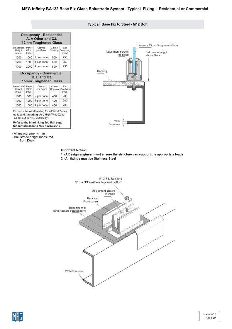
Typical Base Fix to Steel - M12 Bolt
Web 6mm min
Web 6mm min
Important Notes:
1 - A Design engineer must ensure the structure can support the appropriate loads
2 - All fixings must be Stainless Steel
Balustrade Height(max)
Panel Width (max)
Clampsper Panel
Clamp Spacing
End Overhang
(max)
1300 800 2 per panel 400 200
1300 1200 3 per panel 400 200
1300 1600 4 per panel 400 200
Occupancy - Commercial B, E and C3.
15mm Toughened Glass
Occupancy - Residential A, A Other and C3.
12mm Toughened Glass
Balustrade Height(max)
Panel Width (max)
Clampsper Panel
Clamp Spacing
End Overhang
(max)
1200 1000 2 per panel 500 250
1200 1500 3 per panel 500 250
1200 2000 4 per panel 500 250
Exceeds the wind loading for all Wind Zonesup to and Including Very High Wind Zone as set out in NZS 3604:2011
Refer to the Interlinking Top Rail page for conformance to NZS 4223.3.2016
Base channel (and Packers if necessary)
M12 SS Bolt and21dia SS washers top and bottom
Balustrade heightabove Deck
12mm or 15mm Toughened Glass
Adjustment screws to inside
Back andFront covers
Adjustment screws to inside
- Typical Fixing - Residential or CommercialMFG Infinity BA122 Base Fix Glass Balustrade System
- All measurements mm- Balustrade height measured from Deck
Issue 9/16
Page 30
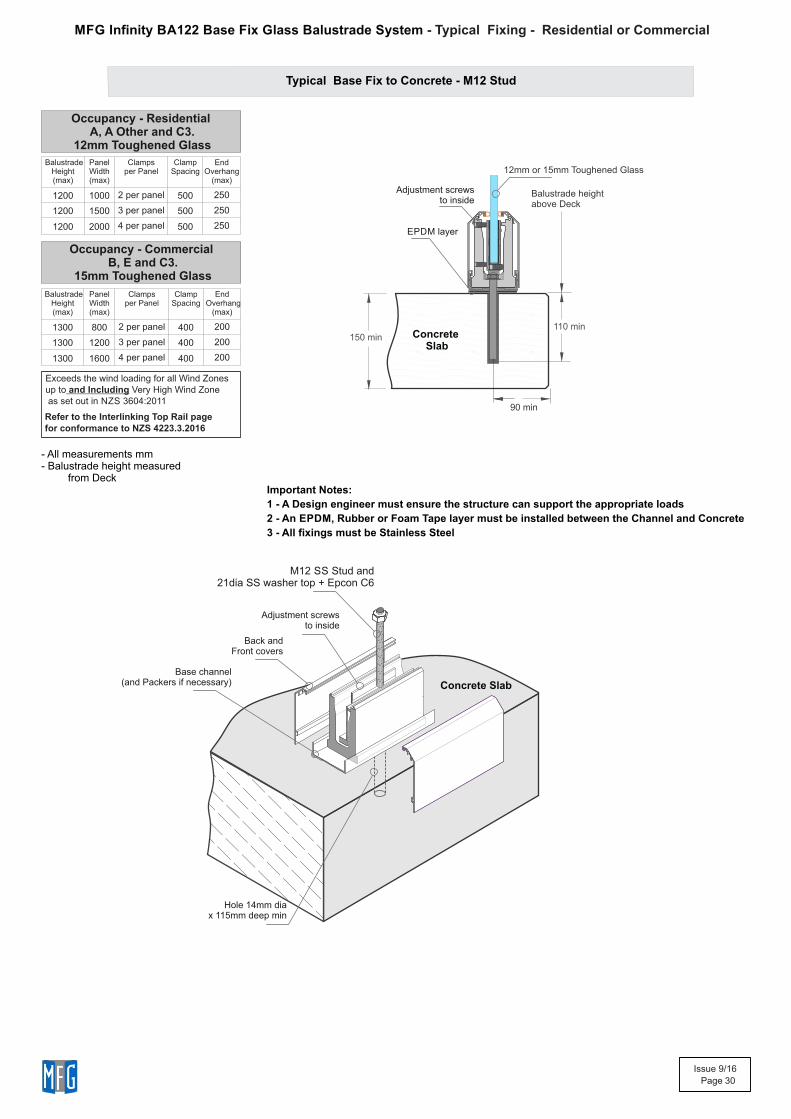
Concrete Slab
Hole 14mm dia x 115mm deep min
150 min110 min
Typical Base Fix to Concrete - M12 Stud
EPDM layer
Important Notes:
1 - A Design engineer must ensure the structure can support the appropriate loads
2 - An EPDM, Rubber or Foam Tape layer must be installed between the Channel and Concrete
3 - All fixings must be Stainless Steel
Balustrade Height(max)
Panel Width (max)
Clampsper Panel
Clamp Spacing
End Overhang
(max)
1300 800 2 per panel 400 200
1300 1200 3 per panel 400 200
1300 1600 4 per panel 400 200
Occupancy - Commercial B, E and C3.
15mm Toughened Glass
Occupancy - Residential A, A Other and C3.
12mm Toughened Glass
Balustrade Height(max)
Panel Width (max)
Clampsper Panel
Clamp Spacing
End Overhang
(max)
1200 1000 2 per panel 500 250
1200 1500 3 per panel 500 250
1200 2000 4 per panel 500 250
Exceeds the wind loading for all Wind Zonesup to and Including Very High Wind Zone as set out in NZS 3604:2011
Refer to the Interlinking Top Rail page for conformance to NZS 4223.3.2016
Balustrade heightabove Deck
12mm or 15mm Toughened Glass
90 min
Back andFront covers
M12 SS Stud and21dia SS washer top + Epcon C6
Concrete Slab
Adjustment screws to inside
Adjustment screws to inside
Base channel (and Packers if necessary)
- Typical Fixing - Residential or CommercialMFG Infinity BA122 Base Fix Glass Balustrade System
- All measurements mm- Balustrade height measured from Deck
Issue 9/16
Page 31
Glass Cleaning and Maintenance
Architectural glass products must be properly cleaned during the construction period so visual and aesthetic clarity are maintained. Because glass can
be permanently damaged if improperly cleaned, glass producers and fabricators recommend strict compliance with the following procedures.
First, determine whether the glass is clear, tinted or reflective. Surface damage is more noticeable on reflective glass compared with the other glass
products. If the reflective coated surface is exposed, either on the exterior or interior, special care must be taken when cleaning, as scratches can
result in coating removal and a visible change in light transmittance. Cleaning tinted and reflective glass in direct sunlight should be avoided. Cleaning
should begin at the top of the building and continue to the lower levels.
Commence cleaning by soaking the glass surfaces with clean water and a soap solution to loosen dirt or debris. Then, using a mild, non-abrasive
commercial window washing solution, uniformly apply the solution to the glass surfaces with a non-abrasive applicator and follow with a squeegee to
remove all of the cleaning solution from the glass surface.
Ensure that no metal parts of the cleaning equipment touch the glass surface and that no abrasive particles are trapped between the glass and the
cleaning materials. All water and cleaning solution residue should be dried from the window gaskets, sealants and frames.
Scratches and Metal Scrapers
Scratches can occur from hard pointed objects or poor handling, but most often occurs from the careless removal of foreign matter from the glass
surface.
Mortar splatter and paint are common offenders and efforts to remove after hardening almost always lead to surface damage. It is essential that the
foreign materials are removed before they harden. Better still, if construction work continues after glazing, that the glazed areas are protected by
adhesive plastic films or suitable tarpaulins or covers.
One of the common mistakes made by non-glass trades people, including glass cleaning contractors, is the use of razor blades or other metal
scrapers on a large portion of the glass surface. Using large blades to scrape a window clean carries considerable risk of causing damage to the
glass.
The glass industry, fabricators, distributors and installers neither condones nor recommends any scraping of glass surfaces with metal blades or
knives. Such scraping usually permanently damages or scratches the glass surfaces. When paint or other construction materials cannot be removed
with normal cleaning procedures, a new 25mm razor blade may have to be used. The razor blade should be used on small spots only. Cleaning should
be done in one direction only. Never scrape in a back and forth motion as this could trap particles under the blade that could scratch the glass.
Blades or scrapers can dislodge “pickup” on toughened glass. There are fine particles of glass that are fused on to the surface during toughening.
Once dislodged they can scratch the glass.
Glass Cleaning, Do’s and Don’ts
DO NOT..
- Do Not - Use Scrapers of any type or size on a Glass surface
- Do Not - Leave building dirt or residues to remain on Glass for a period of time.
- Do Not - Begin cleaning glass until you have identified the surface type.
- Do Not - Clean Glass surfaces in direct sunlight.
- Do Not - Allow dirty water or cleaning residues to remain on the Glass.
- Do Not - Begin cleaning before rinsing off a loose residues.
- Do Not - Use abrasive cleaning solutions, materials or solvents.
- Do Not - Allow metal parts of the cleaning equipment to come in contact with the Glass.
- Do Not - Trap abrasive particles between the cleaning material and the Glass.
DO...
- Clean glass promptly when dirt or building residues appear.
- Determine glass surface type.
- Exercise special care when cleaning coated surfaces.
- Avoid cleaning glass surfaces in direct sunlight.
- Start cleaning at the top of a building, then continue to lower levels.
- Soak the glass surface in a clean soapy solution before cleaning.
- Use a mild non abrasive commercial cleaner.
- Use a squeege to remove all cleaning solution.
- Try your procedures on a small window and check.
- Caution other trades re the care and protection of the glass surfaces.
Residues of surface grit may be present from the toughening production process.These grit particles must not be dragged across the surface.
NEVER use Metal Scrapers
All above reprinted with permission from Metro Glass Tech
MFG Infinity Glass Balustrade System - Glass Care
Issue 9/16
Page 32
MFG Infinity Glass Balustrade System - Powder Coating Care
Warning re use of solvents:
- In some cases strong solvents are recommended for thinning various types of paints and also for cleaning up mastics and sealants.
- These can be harmful to the extended life of the powder coated surface, and must not be used for cleaning purposes.
- It is important to note that the damage will not be visible immediately and may take up to l2 months to develop.
If paint splashes or sealants and mastics need to be removed then the following may be safely used:
Methylated Spirits, Ethyl Alcohol, lsopropanol or preferably a mild detergent in warm water.
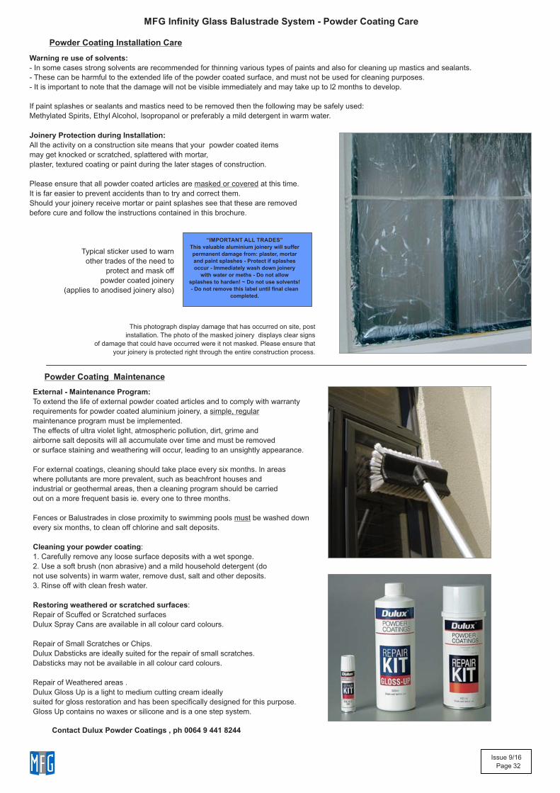
Joinery Protection during Installation:
All the activity on a construction site means that your powder coated items
may get knocked or scratched, splattered with mortar,
plaster, textured coating or paint during the later stages of construction.
Please ensure that all powder coated articles are masked or covered at this time.
It is far easier to prevent accidents than to try and correct them.
Should your joinery receive mortar or paint splashes see that these are removed
before cure and follow the instructions contained in this brochure.
“IMPORTANT ALL TRADES”
This valuable aluminium joinery will suffer
permanent damage from: plaster, mortar
and paint splashes - Protect if splashes
occur - Immediately wash down joinery
with water or meths - Do not allow
splashes to harden! ~ Do not use solvents!
- Do not remove this label until final clean
completed.
This photograph display damage that has occurred on site, post
installation. The photo of the masked joinery displays clear signs
of damage that could have occurred were it not masked. Please ensure that
your joinery is protected right through the entire construction process.
External - Maintenance Program:
To extend the life of external powder coated articles and to comply with warranty
requirements for powder coated aluminium joinery, a simple, regular
maintenance program must be implemented.
The effects of ultra violet light, atmospheric pollution, dirt, grime and
airborne salt deposits will all accumulate over time and must be removed
or surface staining and weathering will occur, leading to an unsightly appearance.
For external coatings, cleaning should take place every six months. ln areas
where pollutants are more prevalent, such as beachfront houses and
industrial or geothermal areas, then a cleaning program should be carried
out on a more frequent basis ie. every one to three months.
Fences or Balustrades in close proximity to swimming pools must be washed down
every six months, to clean off chlorine and salt deposits.
Cleaning your powder coating:
1. Carefully remove any loose surface deposits with a wet sponge.
2. Use a soft brush (non abrasive) and a mild household detergent (do
not use solvents) in warm water, remove dust, salt and other deposits.
3. Rinse off with clean fresh water.
Restoring weathered or scratched surfaces:
Repair of Scuffed or Scratched surfaces
Dulux Spray Cans are available in all colour card colours.
Repair of Small Scratches or Chips.
Dulux Dabsticks are ideally suited for the repair of small scratches.
Dabsticks may not be available in all colour card colours.
Repair of Weathered areas .
Dulux Gloss Up is a light to medium cutting cream ideally
suited for gloss restoration and has been specifically designed for this purpose.
Gloss Up contains no waxes or silicone and is a one step system.
Typical sticker used to warn
other trades of the need to
protect and mask off
powder coated joinery
(applies to anodised joinery also)
Powder Coating Maintenance
Powder Coating Installation Care
Contact Dulux Powder Coatings , ph 0064 9 441 8244