Embed Size (px)
Citation preview

Installation Instructions for Infiniium Oscilloscope Performance Upgrade Kits E2633-68701/3 and VoiceControl Upgrade Kit E2633-68704
Infiniium OscilloscopeModels 54810A/15A/20A/25A/45A

2

Infiniium Oscilloscope Models 54810A/15A/20A/25A/45AGeneral
3
General
1 Purpose and ScopeProvides instructions for Agilent Service Center personnel to upgrade HP/Agilent 54800 series Infiniium Oscilloscopes using the Performance Upgrade Kits E2633-68701 and E2633-68703. These upgrades bring the Infiniium Oscilloscope computer system up to the equivalent of serial prefix US3919; 300 MHz CPU, LS-120 120MB floppy drive, 64 MB RAM, Windows 98, LAN card (if not already installed) and replacing or restoring the hard drive.
HP/Agilent Infiniium Oscilloscope Performance Upgrade E2633A options 001, 002, 003 and 004 are obsoleted and replaced with service center installable upgrade kits.
Performance Upgrade E2633A Option 001 and 002 are combined and replaced with upgrade kit E2633-68701.
Performance Upgrade E2633A Option 003 is replaced with upgrade kit E2633-68703.
Voice Control Upgrade E2633A Option 004 is replaced with upgrade kit E2633-68704.
Performance Upgrade kit E2633-68703 applies to Infiniium oscilloscopes with serial number prefix US3845. This upgrade kit contains the necessary parts and instructions to upgrade the oscilloscope to Windows 98, the LS-120 floppy drive, the latest oscilloscope application software, hard drive recovery media and miscellaneous hardware.
Performance Upgrade kit E2633-68701 applies to Infiniium oscilloscopes with serial number prefixes less than US3844. This upgrade kit includes all the necessary parts and instructions to upgrade the oscilloscope computer from 100/200 MHz to 300 MHz CPU, increasing RAM to 64 MB, add LAN card if needed, Windows 98, the LS-120 floppy drive, the latest oscilloscope application software, a new hard drive, hard drive recovery media, and miscellaneous hardware.
VoiceControl Upgrade kit E2633-68704 contains the necessary hardware and software to add voice control to the above upgrades.
2 Electrostatic Discharge Precautions.All personnel must strictly adhere to all requirements pertaining to Electrostatic Discharge Control (ESD) when the oscilloscope is open.

Infiniium Oscilloscope Models 54810A/15A/20A/25A/45AParts Supplied
4
Parts Supplied
The following table lists the parts supplied in Performance Upgrade Kit E2633-68701
Parts Included in Kit E2633-68701
Agilent Part Number Description
54810-66524 PC Motherboard, AMI series 757 (A4)
1818-7682 DRAM SIMM, 32 Mbyte, Qty 2 (A4A2/3)
0950-3399 DC-DC Converter 2.2V (A4A4)
1821-4976 CPU, AMD-K6-2/300 AFR (A4A1)
54810-68501 CPU Heatsink/fan assy (B2)
1150-2064 LAN Card, Accton ISA 142688-400 (A15)
54810-83512 HDD, 2.5” SW A.03.50 for AMI config (A9)
54801-01208 Hard drive mounting bracket (MP57)
0950-3931 LS-120 floppy drive (A10)
54810-66531 IDE Adapter board w/ three connectors (A18)
54801-01210 Bracket-Adapter board (MP74)
54810-85401 Insulator-floppy drive (MP73)
54801-61607 Cable assy-PC power (W5)
54801-61643 Cable assy-A18 board to hard drive (W10)
54810-68742 Recovery SW, LS-120 Win98 V3.5 (for VIN#25 units only)
54810-68XXX Upgrade SW, LS-120 Rev. 4.21 or higher
N1455-10002 WIN98 Certif. of Authenticity
0515-2691 MS M2.6X0.45 6MM-LG PAN-HD T8 w/Patchlock
0515-0372 MS M3X0.5 8MM-LG T10
E2633-97000 These Installation Instructions

Infiniium Oscilloscope Models 54810A/15A/20A/25A/45AParts Supplied
5
Parts Included in Performance Upgrade Kit E2633-68703
Parts Included in Voice Control Upgrade Kit E2633-68704
Tools Required to Perform Upgrade
• T-8 Torx Driver• T-10 Torx Driver• T-15 Torx Driver• Long Nose Pliers
Agilent Part Number Description
0950-3931 LS-120 floppy drive (A10)
54810-66531 IDE Adapter board w/ three connectors (A18)
54801-01210 Bracket-Adapter board (MP74)
54810-85401 Insulator-floppy drive (MP73)
54801-61607 Cable assy-PC power (W5)
54801-61643 Cable assy-A18 board to hard drive (W10)
54810-68742 Recovery SW, LS-120 Win98 V3.5 (for VIN#25 units only)
54810-68XXX Upgrade SW, LS-120 Rev. 4.21 or higher
N1455-10002 WIN98 Certif. of Authenticity
0515-2691 MS M2.6X0.45 6MM-LG PAN-HD T8 w/Patchlock
0515-0372 MS M3X0.5 8MM-LG T10
E2633-97000 These Installation Instructions
Agilent Part Number Description
1150-2091 Sound Card-16 Bit ISA (Sound Blaster CT4170)
54810-68763 Infiniium Voice Control SW Packet
E2636-68701 Microphone assembly

Infiniium Oscilloscope Models 54810A/15A/20A/25A/45AE2633-69701/E2633-68703/E2633-68704 Upgrade Process
6
E2633-69701/E2633-68703/E2633-68704 Upgrade Process
1 Remove sleeve by placing the oscilloscope face down on a soft protective surface. Use a T-15 Torx driver and remove the 4 screws from rear bumpers. Remove the 4 screws from the rear sleeve of the oscilloscope. Remove the 2 screws retaining the side handle.
Figure 1

Infiniium Oscilloscope Models 54810A/15A/20A/25A/45AE2633-69701/E2633-68703/E2633-68704 Upgrade Process
7
2 Carefully lift the sleeve from the oscilloscope being careful not to snag the sleeve on the ribbon cables in the bottom of the unit.
Figure 2.

Infiniium Oscilloscope Models 54810A/15A/20A/25A/45AE2633-69701/E2633-68703/E2633-68704 Upgrade Process
8
3 Remove the retaining screws holding the plug-in cards.(Skip this step on upgrade kit E2633-68703 since the motherboard is not replaced.)
Figure 3

Infiniium Oscilloscope Models 54810A/15A/20A/25A/45AE2633-69701/E2633-68703/E2633-68704 Upgrade Process
9
4 Disconnect the cables as shown and dress these cables out of the way. Then remove the 1.44 MB floppy disk drive using a T-8 driver. Slide the drive out the front.(For upgrade kit E2633-68703, remove and discard the FDD cable also.)
Figure 4
T-8
T-8
FDD Cable

Infiniium Oscilloscope Models 54810A/15A/20A/25A/45AE2633-69701/E2633-68703/E2633-68704 Upgrade Process
10
5 After removing the plug-in cards, remove the motherboard retaining screws, then carefully remove the old motherboard as shown.(For upgrade kit E2633-68703 skip this step since the motherboard is not replaced.)
Figure 5

Infiniium Oscilloscope Models 54810A/15A/20A/25A/45AE2633-69701/E2633-68703/E2633-68704 Upgrade Process
11
6 Turn the instrument over and disconnect the PC power cable W5 from the acquisition board then remove the cable from the instrument. Install the new PC power cable p/n 54801-61607 included in the kit. The new cable has another power connector that is needed to supply power into the new adapter board p/n 54810-66531 that is installed in step 15.)
Figure 6
W5

Infiniium Oscilloscope Models 54810A/15A/20A/25A/45AE2633-69701/E2633-68703/E2633-68704 Upgrade Process
12
7 Set up the new PC motherboard as follows:Verify the motherboard jumpers are as follows:
(For upgrade kit E2633-68703, skip to step 10 after verifying the above motherboard jumpers.)
Install the two new 32 MB RAM memory sticks.
Install the new K6-2/300 microprocessor (CPU) into the ZIP socket.
Clean the CPU top with alcohol and install the new heatsink/fan onto the CPU, then connect the fan cable to J13. The colored fan lead must connect to Pin 1.
Connect the PS/2 mouse cable connector to PS/2 connector on motherboard.
Connect the IDE cable to the Primary IDE connector. The ribbon cable is oriented red-stripe to pin 1 on connector.
Install the Voltage Regulator Module (VRM) in the motherboard VRM connector socket.
MOTHERBOARD JUMPERS OPEN/SHORTED
J5 OPEN
J6 SHORTED
J7 SHORTED
J8 SHORTED
J16 SHORTED
J14 ALL PINS OPEN
J15 SET TO 33 MHZ

Infiniium Oscilloscope Models 54810A/15A/20A/25A/45AE2633-69701/E2633-68703/E2633-68704 Upgrade Process
13
Figure 7
8 Close-up view of Jumpers J5-8, J16 and J14 (J9-12 are set to 512K). Identify the jumper numbers by the printing on the board.
Figure 8
J5-8, J16 & J14
J15
VRM
CPU & CPU heatsink/fan
PS/2 mouse cable
New RAM sticks
IDE cable

Infiniium Oscilloscope Models 54810A/15A/20A/25A/45AE2633-69701/E2633-68703/E2633-68704 Upgrade Process
14
9 After setting up the jumpers on new motherboard and attaching the cables, carefully install the motherboard as shown.
Be SURE to slide the motherboard INTO the nylon retaining guide H23 (retaining guide is located on the deck under the floppy drive bracket).
Install the 8 screws fastening the motherboard to the chassis deck.
Figure 9
Be SURE to insert motherbrdcorner properlyinto H23 nylonRetaining Guideslot!

Infiniium Oscilloscope Models 54810A/15A/20A/25A/45AE2633-69701/E2633-68703/E2633-68704 Upgrade Process
15
10 Carefully install the one parallel port and the two serial port cables. Be sure these are installed correctly onto the appropriate motherboard connectors.
Figure 10
11 The two power plugs are connected so that the black wires on one plug are adjacent to the black wires on the second plug. The rule is: Black-to-Black.
Figure 11
COMM(SERIAL)1
COMM(SERIAL)2
PARALLEL
PORT
BLACK WIRES

Infiniium Oscilloscope Models 54810A/15A/20A/25A/45AE2633-69701/E2633-68703/E2633-68704 Upgrade Process
16
12 Place the floppy drive insulator, MP73 p/n 54810-85401, onto the floppy drive platform.
Figure 12
13 Install the new LS-120 floppy drive while holding the floppy insulator in place.
Figure 13
Infiniium Oscilloscope Models 54810A/15A/20A/25A/45AE2633-69701/E2633-68703/E2633-68704 Upgrade Process
17
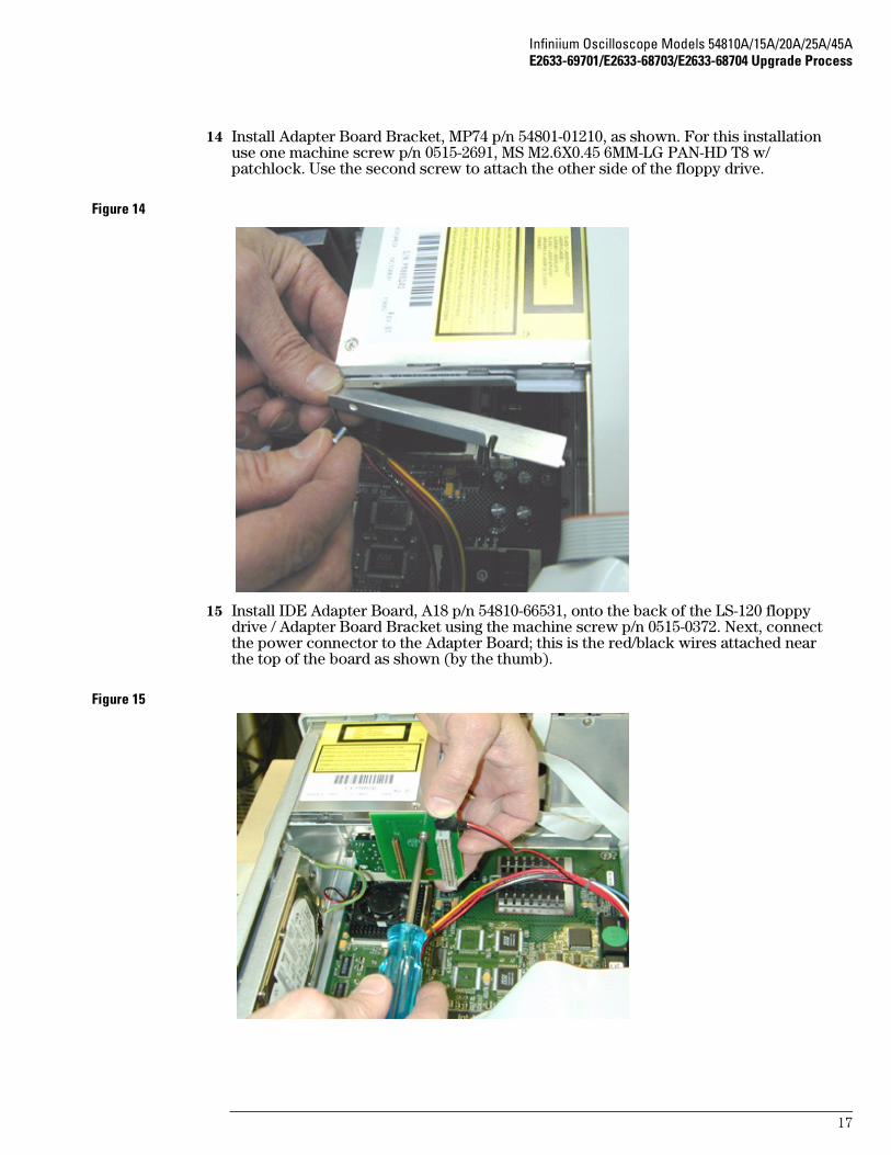
14 Install Adapter Board Bracket, MP74 p/n 54801-01210, as shown. For this installation use one machine screw p/n 0515-2691, MS M2.6X0.45 6MM-LG PAN-HD T8 w/ patchlock. Use the second screw to attach the other side of the floppy drive.
Figure 14
15 Install IDE Adapter Board, A18 p/n 54810-66531, onto the back of the LS-120 floppy drive / Adapter Board Bracket using the machine screw p/n 0515-0372. Next, connect the power connector to the Adapter Board; this is the red/black wires attached near the top of the board as shown (by the thumb).
Figure 15

Infiniium Oscilloscope Models 54810A/15A/20A/25A/45AE2633-69701/E2633-68703/E2633-68704 Upgrade Process
18
16 Carefully install the new hard drive cable p/n 54801-61643 between the hard drive and the Adapter Board as shown. Notice the connectors are keyed; the red stripe on ribbon cable goes to pin 1 on connectors. Next, install the IDE cable from motherboard Primary IDE connector to other Adapter Board connector.
Figure 16

Infiniium Oscilloscope Models 54810A/15A/20A/25A/45AE2633-69701/E2633-68703/E2633-68704 Upgrade Process
19
17 Re-install the plug-in cards this order from slot nearest the hard drive: PCI Slot 1 - Not used
PCI Slot 2 - Scope Interface board A6
PCI Slot 3 - Display board A5
PCI Slot 4 - None
ISA Slot 1 - For the Voice Control Upgrade E2633-68704 install the ISA sound card; otherwise - None
ISA Slot 2 - LAN card A15
ISA Slot 3 - GPIB board A14
ISA Slot 4 - Not used
Install the retaining screws
For upgrade kit E2633-68701, install the new hard drive on the new drive bracket and install in place of the old hard drive. On upgrade kit E2633-68703, the hard drive is not replaced, it is simply remastered in step 20.
(The sound card for the Voice Control Upgrade E2633-68704 is not shown in this photo.)
Figure 17

Infiniium Oscilloscope Models 54810A/15A/20A/25A/45AE2633-69701/E2633-68703/E2633-68704 Upgrade Process
20
18 Connect the remainder of the cables as shown.Carefully check that all the motherboard cabling is correct especially the motherboard IDE port cabling. Verify that the unit is completely assembled except for the cabinet sleeve.
Figure 18
These cablesareeliminated

Infiniium Oscilloscope Models 54810A/15A/20A/25A/45AE2633-69701/E2633-68703/E2633-68704 Upgrade Process
21
19 Connect a keyboard, mouse and power cord.While holding down the Insert key on the keyboard, turn on the power. When a display comes on screen, press F1 to run setup. The following display should be on screen after pressing F1.
Figure 19
BIOS Setup Procedure
a Double-click on Optimal Defaults. Click Yes in response to “Load Optimal Values?”b Double-click on Standard Setup, select Date/Time. Use the mouse to set the current
month, day, year, and time. When finished, exit the Date/Time block.
c Under Standard Setup, select Pri Master, select Auto, exit Primary Master block.
d Under Standard Setup, select Pri Slave, select Floptical, exit Primary Slave block.
e Under Standard Setup, select Floppy A, select Not Installed, exit Floppy A block.
f Under Standard Setup, select Floppy B, select Not Installed, exit Floppy B block, then exit Standard Setup.
g Select Advanced Setup, then select System Keyboard. Select Absent (not installed).
h Under Advanced Setup, scroll down to 1st Boot Device and select Floptical.
i Under Advanced Setup, select 2nd Boot Device and select IDE-0.
j Exit Advanced Setup.
k Double-click PCI/PnP Setup, then scroll down to select IRQ9. Select ISA, then exit PCI/PnP Setup.
l Double-click on Peripheral Setup, then select OnBoard Primary/Secondary IDE. Select Primary, then exit Peripheral Setup by clicking on the box in the upper left corner.
m Double-click on Power Management.
n Click Power Management/APM and select Enabled. (This line may be shadowed out.)
System Keyboard Absent
This tells the computer not to check the keyboard during the power-on self test. The keyboard will still function after this.

Infiniium Oscilloscope Models 54810A/15A/20A/25A/45AE2633-69701/E2633-68703/E2633-68704 Upgrade Process
22
o Click Hard Drive Power Down Mode and select Suspend.
p Click Hard Drive Time Out (Minute) and select 15 min.
q Exit Power Management Setup.
r Exit AMIBIOS Setup by clicking on the box in the upper left corner, select Save Changes and Exit.
s The oscilloscope should reboot, load Windows 98, and come up with the oscilloscope display. If it does not, recheck your steps in the above procedure. If all settings are correct, re-check all the motherboard jumper settings, upgrade steps and especially the cabling connections on the motherboard for errors.

Infiniium Oscilloscope Models 54810A/15A/20A/25A/45AE2633-69701/E2633-68703/E2633-68704 Upgrade Process
23
20 For upgrade E2633-68703 the hard drive is not replaced. Therefore, remaster the existing hard drive using the LS-120 Recovery Packet A.03.50 floppies shipped with this kit.
Figure 20
21 Turn off the power on the Infiniium Oscilloscope and insert Revision A.03.50 Recovery Disk 1, p/n 54810-17907, in the floppy drive and turn on the power. The above display should appear, click on Recover Drive; insert Recovery Disk 2, p/n 54810-17908, and press “OK” when prompted for disk 2.
22 After the hard drive recovery is complete, cycle power and allow the Infiniium to boot into the oscilloscope mode. It may be necessary to cycle the power a second time if the unit stops responding.
23 On the menu bar, select Utilities, then select Self Test.24 Check that all probes and cables are disconnected from the oscilloscope inputs. Select
Start to run the self test. Follow the prompts on the screen.
Figure 21
25 After self test has completed (this may take several minutes), select the Close button.

Infiniium Oscilloscope Models 54810A/15A/20A/25A/45AE2633-69701/E2633-68703/E2633-68704 Upgrade Process
24
26 Find the Infiniium Operating System Software Upgrade Disk, Revision A.04.21 or higher software, in the kit and upgrade the operating system software by the following step.
27 Insert disk in the floppy drive. Select Utilities, Upgrade Software and follow directions on the screen.
Figure 22
28 Enter the oscilloscope serial number by selecting Help, About Infiniium, then Change Serial Number. The serial number can be entered by either the mouse or the keyboard.
Figure 23

Infiniium Oscilloscope Models 54810A/15A/20A/25A/45AE2633-69701/E2633-68703/E2633-68704 Upgrade Process
25
E2633-68704 VoiceControl Upgrade
29 If the upgrade includes the VoiceControl Upgrade Kit E2633-68704, install the sound card and the Voice Control Software in the following steps; otherwise skip to the Install Cabinet Sleeve Step 42.
30 Turn off the Infiniium oscilloscope and install Sound Card p/n 1150-2091 in ISA Slot 1 on the motherboard.
Figure 24
31 After installing the sound card, check all the cable connections, then turn-on the power. The oscilloscope should boot up and find various Plug-and-Play (PnP) devices such shown in the next picture.
Figure 25
32 Restart the Infiniium oscilloscope when prompted.
Infiniium Oscilloscope Models 54810A/15A/20A/25A/45AE2633-69701/E2633-68703/E2633-68704 Upgrade Process
26
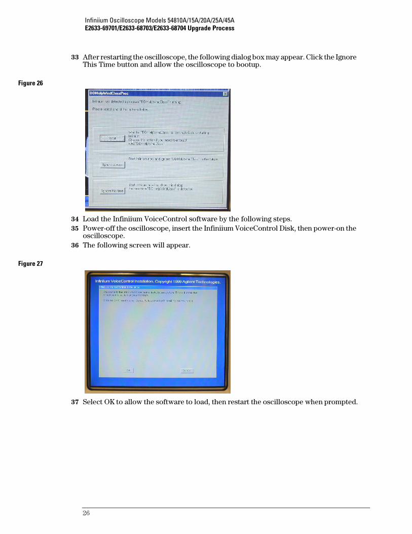
33 After restarting the oscilloscope, the following dialog box may appear. Click the Ignore This Time button and allow the oscilloscope to bootup.
Figure 26
34 Load the Infiniium VoiceControl software by the following steps.35 Power-off the oscilloscope, insert the Infiniium VoiceControl Disk, then power-on the
oscilloscope. 36 The following screen will appear.
Figure 27
37 Select OK to allow the software to load, then restart the oscilloscope when prompted.

Infiniium Oscilloscope Models 54810A/15A/20A/25A/45AE2633-69701/E2633-68703/E2633-68704 Upgrade Process
27
38 Test the VoiceControl by the following:39 Plug the microphone connector in the Mic In jack on the rear panel of the oscilloscope.
Turn on the microphone by pressing the microphone switch button.40 Select Utilities, VoiceControl, Active VoiceControl, finally click the Voice Tutor button.
Go through the Voice Tutor to verify the VoiceControl functions.
Figure 28
41 When everything is functioning properly, continue on to the next step.42 Install the cabinet sleeve as shown below. Please be careful to not damage the ribbon
cables while installing the cabinet sleeve.
Figure 29
Tuck ribbon cablesout of the way to avoid damage

Infiniium Oscilloscope Models 54810A/15A/20A/25A/45AE2633-69701/E2633-68703/E2633-68704 Upgrade Process
28
43 Install rear feet, the side handle and tighten all the screws. Tighten the side handle screws to approximately 18 inch-lbs.
Figure 30

Infiniium Oscilloscope Models 54810A/15A/20A/25A/45AE2633-69701/E2633-68703/E2633-68704 Upgrade Process
29
44 After installing the cabinet sleeve, turn on the power and allow to warm-up for 30 minutes. After 30 minutes, select Utilities on the menu bar, then select Calibration.
Figure 31
45 Un-select the Cal Memory Protect box, then select Start to initiate the self-cal. Follow the instructions given on the screen to complete the selfcalibration.
Figure 32
46 After the self calibration finishes, select Close.47 Check the general oscilloscope operation.48 If the customer has ordered a Calibration, run then performance tests to verify that the
unit meets specifications.

Infiniium Oscilloscope Models 54810A/15A/20A/25A/45AE2633-69701/E2633-68703/E2633-68704 Upgrade Process
30
49 Apply labels to rear panel as shown.
Figure 33
50 This completes the upgrade.

31

s1
Agilent Technologies
Printed in the USA
Manual Part Number
E2633-97000
����������