Embed Size (px)
Citation preview
Infant WarmerOPERATIONS AND MAINTENANCE MANUALFor Parts or Technical Assistance1–800–327–0770
IMPORTANTFile in yourmaintenancerecords
Table of Contents
IntroductionSpecifications 2. . . . . . . . . . . . . . . . . . . . . . . . . . . . . . . . . . . . . . . . . . . . . . . . . . . . . . . . . . . . . . . . . . . . . . . . . . Warning / Caution / Note Definition 2. . . . . . . . . . . . . . . . . . . . . . . . . . . . . . . . . . . . . . . . . . . . . . . . . . . . . . . .
Infant Warmer Illustration 3. . . . . . . . . . . . . . . . . . . . . . . . . . . . . . . . . . . . . . . . . . . . . . . . . . . . . . . . . . . . . . . . . . . .
Operation Guide
Infant Warmer Operation 4. . . . . . . . . . . . . . . . . . . . . . . . . . . . . . . . . . . . . . . . . . . . . . . . . . . . . . . . . . . . . . . . . Before Putting The Infant On The Warmer 4. . . . . . . . . . . . . . . . . . . . . . . . . . . . . . . . . . . . . . . . . . . . . . . . . After Putting The Infant On The Warmer 4. . . . . . . . . . . . . . . . . . . . . . . . . . . . . . . . . . . . . . . . . . . . . . . . . . . System Check 5. . . . . . . . . . . . . . . . . . . . . . . . . . . . . . . . . . . . . . . . . . . . . . . . . . . . . . . . . . . . . . . . . . . . . . . . . . Nurse Call 5. . . . . . . . . . . . . . . . . . . . . . . . . . . . . . . . . . . . . . . . . . . . . . . . . . . . . . . . . . . . . . . . . . . . . . . . . . . . . Temperature Display Settings 5. . . . . . . . . . . . . . . . . . . . . . . . . . . . . . . . . . . . . . . . . . . . . . . . . . . . . . . . . . . .
Preventative Maintenance
Preventative Maintenance Program 6. . . . . . . . . . . . . . . . . . . . . . . . . . . . . . . . . . . . . . . . . . . . . . . . . . . . . . . Cleaning 6. . . . . . . . . . . . . . . . . . . . . . . . . . . . . . . . . . . . . . . . . . . . . . . . . . . . . . . . . . . . . . . . . . . . . . . . . . . . . . .
Troubleshooting 7. . . . . . . . . . . . . . . . . . . . . . . . . . . . . . . . . . . . . . . . . . . . . . . . . . . . . . . . . . . . . . . . . . . . . . . . . . . .
System Check Alarm Codes 8. . . . . . . . . . . . . . . . . . . . . . . . . . . . . . . . . . . . . . . . . . . . . . . . . . . . . . . . . . . . . . Schematic Diagrams 9–12. . . . . . . . . . . . . . . . . . . . . . . . . . . . . . . . . . . . . . . . . . . . . . . . . . . . . . . . . . . . . . . . . . . . .
Service Information 13. . . . . . . . . . . . . . . . . . . . . . . . . . . . . . . . . . . . . . . . . . . . . . . . . . . . . . . . . . . . . . . . . . . . . . . .
Verifying Accuracy Of Temperature Readings 13. . . . . . . . . . . . . . . . . . . . . . . . . . . . . . . . . . . . . . . . . . . . . . Membrane Switch Replacement 14. . . . . . . . . . . . . . . . . . . . . . . . . . . . . . . . . . . . . . . . . . . . . . . . . . . . . . . . . Display Circuit Board Replacement 14. . . . . . . . . . . . . . . . . . . . . . . . . . . . . . . . . . . . . . . . . . . . . . . . . . . . . . . Control Circuit Board Replacement 15. . . . . . . . . . . . . . . . . . . . . . . . . . . . . . . . . . . . . . . . . . . . . . . . . . . . . . . Fan Replacement 15. . . . . . . . . . . . . . . . . . . . . . . . . . . . . . . . . . . . . . . . . . . . . . . . . . . . . . . . . . . . . . . . . . . . . . Heater Replacement 16. . . . . . . . . . . . . . . . . . . . . . . . . . . . . . . . . . . . . . . . . . . . . . . . . . . . . . . . . . . . . . . . . . . Thermostat Switch Replacement 16. . . . . . . . . . . . . . . . . . . . . . . . . . . . . . . . . . . . . . . . . . . . . . . . . . . . . . . . . Blanket Warmer Heater/Fan Replacement 17. . . . . . . . . . . . . . . . . . . . . . . . . . . . . . . . . . . . . . . . . . . . . . . . Blanket Warmer Thermostat Switch Replacement 17. . . . . . . . . . . . . . . . . . . . . . . . . . . . . . . . . . . . . . . . . . Ground Fault Interrupt Replacement 18. . . . . . . . . . . . . . . . . . . . . . . . . . . . . . . . . . . . . . . . . . . . . . . . . . . . . . Temperature Display Selection 18. . . . . . . . . . . . . . . . . . . . . . . . . . . . . . . . . . . . . . . . . . . . . . . . . . . . . . . . . . . Temperature Conversion Guide 19. . . . . . . . . . . . . . . . . . . . . . . . . . . . . . . . . . . . . . . . . . . . . . . . . . . . . . . . . .
Field Replacement Parts 20. . . . . . . . . . . . . . . . . . . . . . . . . . . . . . . . . . . . . . . . . . . . . . . . . . . . . . . . . . . . . . . . . . .
Assembly Drawings and Parts Lists
Infant Warmer Assembly 22,23. . . . . . . . . . . . . . . . . . . . . . . . . . . . . . . . . . . . . . . . . . . . . . . . . . . . . . . . . . . . . Cabinet Assembly 24. . . . . . . . . . . . . . . . . . . . . . . . . . . . . . . . . . . . . . . . . . . . . . . . . . . . . . . . . . . . . . . . . . . . . Plenum Assembly 25. . . . . . . . . . . . . . . . . . . . . . . . . . . . . . . . . . . . . . . . . . . . . . . . . . . . . . . . . . . . . . . . . . . . . . Power Panel Assembly 26. . . . . . . . . . . . . . . . . . . . . . . . . . . . . . . . . . . . . . . . . . . . . . . . . . . . . . . . . . . . . . . . . Display Assembly 27. . . . . . . . . . . . . . . . . . . . . . . . . . . . . . . . . . . . . . . . . . . . . . . . . . . . . . . . . . . . . . . . . . . . . . Blanket Box Assembly 28. . . . . . . . . . . . . . . . . . . . . . . . . . . . . . . . . . . . . . . . . . . . . . . . . . . . . . . . . . . . . . . . . . Fan/Heater Assembly 29. . . . . . . . . . . . . . . . . . . . . . . . . . . . . . . . . . . . . . . . . . . . . . . . . . . . . . . . . . . . . . . . . . Electrical Assembly 30. . . . . . . . . . . . . . . . . . . . . . . . . . . . . . . . . . . . . . . . . . . . . . . . . . . . . . . . . . . . . . . . . . . . Tilt Tray Assembly 31. . . . . . . . . . . . . . . . . . . . . . . . . . . . . . . . . . . . . . . . . . . . . . . . . . . . . . . . . . . . . . . . . . . . . Power Relay Assembly 32. . . . . . . . . . . . . . . . . . . . . . . . . . . . . . . . . . . . . . . . . . . . . . . . . . . . . . . . . . . . . . . . . Shelf Assembly 33. . . . . . . . . . . . . . . . . . . . . . . . . . . . . . . . . . . . . . . . . . . . . . . . . . . . . . . . . . . . . . . . . . . . . . . .
WarrantyObtaining Parts and Service 34. . . . . . . . . . . . . . . . . . . . . . . . . . . . . . . . . . . . . . . . . . . . . . . . . . . . . . . . . . . . . Supplemental Warranty Coverage 34. . . . . . . . . . . . . . . . . . . . . . . . . . . . . . . . . . . . . . . . . . . . . . . . . . . . . . . . Return Authorization 35. . . . . . . . . . . . . . . . . . . . . . . . . . . . . . . . . . . . . . . . . . . . . . . . . . . . . . . . . . . . . . . . . . . Freight Damage Claims 35. . . . . . . . . . . . . . . . . . . . . . . . . . . . . . . . . . . . . . . . . . . . . . . . . . . . . . . . . . . . . . . . .
2
Introduction
INTRODUCTION
This manual is designed to assist you with the operation and maintenance of the Adel 986W Infant Warmer.Read it thoroughly before using the equipment or beginning any maintenance on it.
SPECIFICATIONS� 900 watt heater (main), 70 watt heater (blanket box)
� 12 watt fan (main), 4 watt fan (blanket box)
� 120 volt, 50/60 Hz, 12 ampere rating, 105–135 VAC operating ranges
� Current leakage less than 30 microamperes
� Hospital grade plug and 3 wire 14/3 AWG power cord
� 12 ampere resettable circuit breaker
� Compatible with non–flammable anesthetic agents and oxygen by nasal catheter or mask
� Ground Fault Interrupt (located inside back cover)
� Hardwood, hardwood laminate; 43” high X 31 1/2” wide X 22 1/2” deep (sides up)
� .177 thick polycarbonate side panels trimmed in solid hardwood
� Storage compartment with adjustable shelf
� Blanket warming compartment
� Two divided storage drawers
� Four casters, two locking
� Tray directs air to diffuser; catches fluids and provides Trendelenburg function
� Diffuser distributes air and holds pad
� Display panel monitors temperature system and times postnatal events
Stryker reserves the right to change specifications without notice.
WARNINGThe Infant Warmer is equipped with a hospital grade plug for protection against shock hazard. It must beplugged directly into a properly grounded three–prong receptacle. Grounding reliability can be achieved onlywhen a hospital grade receptacle is used.
WARNING / CAUTION / NOTE DEFINITION
The words WARNING, CAUTION and NOTE carry special meanings and should be carefully reviewed.
WARNINGThe personal safety of the patient or user may be involved. Disregarding this information could result in injuryto the patient or user.
CAUTION
These instructions point out special procedures or precautions that must be followed to avoid damaging theequipment.
NOTEThis provides special information to make maintenance easier or important instructions clearer.
3
Infant Warmer Illustration
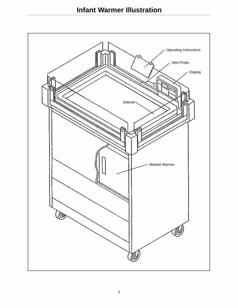
Operating Instructions
Skin Probe
Blanket Warmer
Siderail
Display
4
Operation Guide
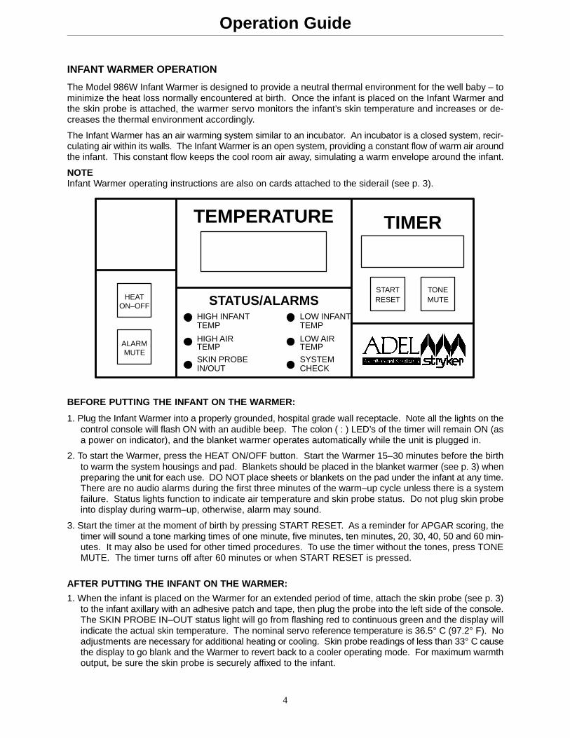
INFANT WARMER OPERATION
The Model 986W Infant Warmer is designed to provide a neutral thermal environment for the well baby – tominimize the heat loss normally encountered at birth. Once the infant is placed on the Infant Warmer andthe skin probe is attached, the warmer servo monitors the infant’s skin temperature and increases or de-creases the thermal environment accordingly.
The Infant Warmer has an air warming system similar to an incubator. An incubator is a closed system, recir-culating air within its walls. The Infant Warmer is an open system, providing a constant flow of warm air aroundthe infant. This constant flow keeps the cool room air away, simulating a warm envelope around the infant.
NOTEInfant Warmer operating instructions are also on cards attached to the siderail (see p. 3).
TEMPERATURE TIMER
STATUS/ALARMSHEATON–OFF
ALARMMUTE
HIGH INFANTTEMP
HIGH AIRTEMP
SKIN PROBEIN/OUT
LOW INFANTTEMP
LOW AIRTEMP
SYSTEMCHECK
STARTRESET
TONEMUTE
BEFORE PUTTING THE INFANT ON THE WARMER:
1. Plug the Infant Warmer into a properly grounded, hospital grade wall receptacle. Note all the lights on thecontrol console will flash ON with an audible beep. The colon ( : ) LED’s of the timer will remain ON (asa power on indicator), and the blanket warmer operates automatically while the unit is plugged in.
2. To start the Warmer, press the HEAT ON/OFF button. Start the Warmer 15–30 minutes before the birthto warm the system housings and pad. Blankets should be placed in the blanket warmer (see p. 3) whenpreparing the unit for each use. DO NOT place sheets or blankets on the pad under the infant at any time.There are no audio alarms during the first three minutes of the warm–up cycle unless there is a systemfailure. Status lights function to indicate air temperature and skin probe status. Do not plug skin probeinto display during warm–up, otherwise, alarm may sound.
3. Start the timer at the moment of birth by pressing START RESET. As a reminder for APGAR scoring, thetimer will sound a tone marking times of one minute, five minutes, ten minutes, 20, 30, 40, 50 and 60 min-utes. It may also be used for other timed procedures. To use the timer without the tones, press TONEMUTE. The timer turns off after 60 minutes or when START RESET is pressed.
AFTER PUTTING THE INFANT ON THE WARMER:
1. When the infant is placed on the Warmer for an extended period of time, attach the skin probe (see p. 3)to the infant axillary with an adhesive patch and tape, then plug the probe into the left side of the console.The SKIN PROBE IN–OUT status light will go from flashing red to continuous green and the display willindicate the actual skin temperature. The nominal servo reference temperature is 36.5° C (97.2° F). Noadjustments are necessary for additional heating or cooling. Skin probe readings of less than 33° C causethe display to go blank and the Warmer to revert back to a cooler operating mode. For maximum warmthoutput, be sure the skin probe is securely affixed to the infant.
5
Operation Guide
AFTER PUTTING THE INFANT ON THE WARMER (CONTINUED):
NOTEAttempts to use the skin probe while drying or assessing the infant may not be successful because it is difficultto get the patch and/or tape to stick on top of the vernix or to withstand excessive handling. To avoid falsealarms, do not use the skin probe until good skin contact can be maintained.
2. Once the infant’s temperature has stabilized (1–4 hours after birth), the Infant Warmer may be turned offby pressing HEAT ON/OFF, and the Warmer can be used as a bassinet for the remainder of the infant’sstay in LDRP. Since the Warmer provides a neutral thermal environment whether the infant is clothed ornot, the unit may be left on as long as the infant skin probe is attached and plugged in.
WARNINGDO NOT LEAVE AN INFANT UNATTENDED.
3. The infant temperature alarm system becomes armed once the temperature reaches the control band.Subsequently, infant temperatures exceeding the 35.5–37.5° C range are indicated by the status lights(flashing red) and the alarm (1Hz). The alarm may be silenced for three minutes by pressing ALARMMUTE. Should another alarm condition be detected during the mute period, the new alarm will activatethe audible alarm and its respective indicator light will flash red.
4. To attain a Trendelenberg position, firmly push down on the foot or head end of the diffuser/pad holder.The Trendelenberg position will be maintained by a self–locking feature. Push down on the opposite endto level the surface or continue pushing to achieve the reverse Trendelenberg position. To intubate, pushthe head end down and open the head end window by lifting up and swinging down the siderail (see p.3).
5. The Infant Warmer pad surface is compatible with direct contact to the infant and is impervious to bodyfluids, vernix, medications and cleaning solutions. Sponge bathing and sponge rinsing can also be per-formed on the pad. Excess fluids and waste products are easily removed from the lower diffuser tray uponthe conclusion of the infant’s stay in the Warmer.
WARNINGThe Infant Warmer should not be exposed to more than 200ml of fluid.
SYSTEM CHECK
System check fault results in a continuous alarm tone which can only be silenced by unplugging the unit fromthe wall. Plug the unit back in to reset. A system check fault lists a code number in the timer display (seetroubleshooting guide p. 8). If the system check alarm cannot be reset, remove the unit from service.
NURSE CALL
The unit is pre–wired to provide a signal to the nurse’s station that an alarm condition exists. The signal(switch actuation) can either open or close the circuit as defined in the existing nurse call communicationssystem. The nurse call signal clears only when the alarm condition clears, not when an alarm condition ismuted on the unit.
TEMPERATURE DISPLAY SETTINGS
The temperature display can be provided in either centigrade or Fahrenheit scales. The unit can also be facto-ry set to operate at 50Hz for international use.
6
Preventative Maintenance
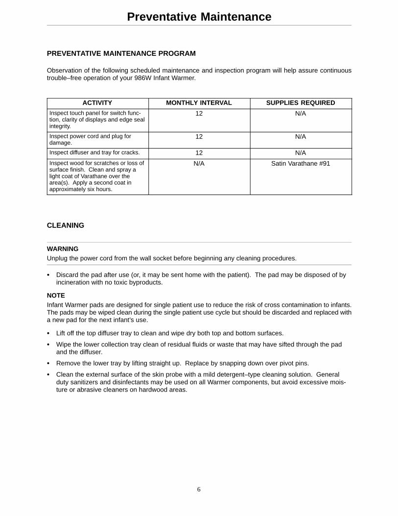
PREVENTATIVE MAINTENANCE PROGRAM
Observation of the following scheduled maintenance and inspection program will help assure continuoustrouble–free operation of your 986W Infant Warmer.
ACTIVITY MONTHLY INTERVAL SUPPLIES REQUIRED
Inspect touch panel for switch func-tion, clarity of displays and edge sealintegrity.
12 N/A
Inspect power cord and plug fordamage.
12 N/A
Inspect diffuser and tray for cracks. 12 N/A
Inspect wood for scratches or loss ofsurface finish. Clean and spray alight coat of Varathane over thearea(s). Apply a second coat inapproximately six hours.
N/A Satin Varathane #91
CLEANING
WARNINGUnplug the power cord from the wall socket before beginning any cleaning procedures.
� Discard the pad after use (or, it may be sent home with the patient). The pad may be disposed of byincineration with no toxic byproducts.
NOTEInfant Warmer pads are designed for single patient use to reduce the risk of cross contamination to infants.The pads may be wiped clean during the single patient use cycle but should be discarded and replaced witha new pad for the next infant’s use.
� Lift off the top diffuser tray to clean and wipe dry both top and bottom surfaces.
� Wipe the lower collection tray clean of residual fluids or waste that may have sifted through the padand the diffuser.
� Remove the lower tray by lifting straight up. Replace by snapping down over pivot pins.
� Clean the external surface of the skin probe with a mild detergent–type cleaning solution. Generalduty sanitizers and disinfectants may be used on all Warmer components, but avoid excessive mois-ture or abrasive cleaners on hardwood areas.
7
Troubleshooting
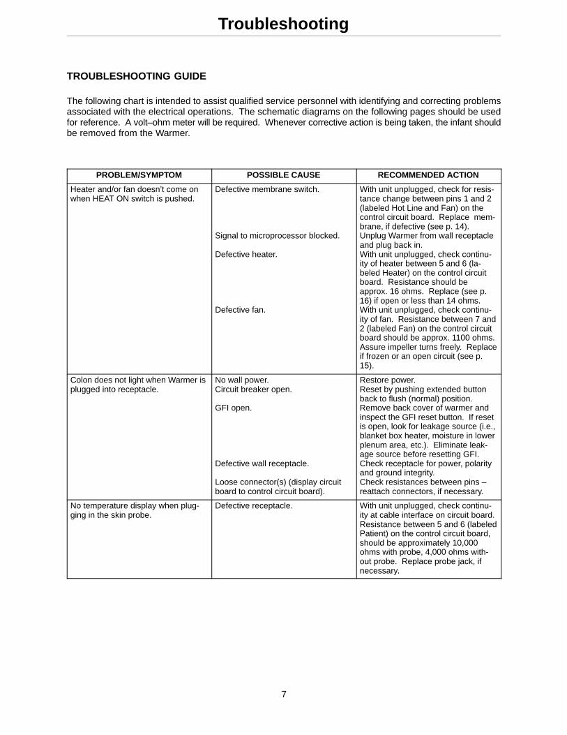
TROUBLESHOOTING GUIDE
The following chart is intended to assist qualified service personnel with identifying and correcting problemsassociated with the electrical operations. The schematic diagrams on the following pages should be usedfor reference. A volt–ohm meter will be required. Whenever corrective action is being taken, the infant shouldbe removed from the Warmer.
PROBLEM/SYMPTOM POSSIBLE CAUSE RECOMMENDED ACTION
Heater and/or fan doesn’t come onwhen HEAT ON switch is pushed.
Defective membrane switch. Signal to microprocessor blocked. Defective heater. Defective fan.
With unit unplugged, check for resis-tance change between pins 1 and 2(labeled Hot Line and Fan) on thecontrol circuit board. Replace mem-brane, if defective (see p. 14).Unplug Warmer from wall receptacleand plug back in.With unit unplugged, check continu-ity of heater between 5 and 6 (la-beled Heater) on the control circuitboard. Resistance should beapprox. 16 ohms. Replace (see p.16) if open or less than 14 ohms.With unit unplugged, check continu-ity of fan. Resistance between 7 and2 (labeled Fan) on the control circuitboard should be approx. 1100 ohms.Assure impeller turns freely. Replaceif frozen or an open circuit (see p.15).
Colon does not light when Warmer isplugged into receptacle.
No wall power.Circuit breaker open. GFI open. Defective wall receptacle. Loose connector(s) (display circuitboard to control circuit board).
Restore power.Reset by pushing extended buttonback to flush (normal) position.Remove back cover of warmer andinspect the GFI reset button. If resetis open, look for leakage source (i.e.,blanket box heater, moisture in lowerplenum area, etc.). Eliminate leak-age source before resetting GFI.Check receptacle for power, polarityand ground integrity.Check resistances between pins –reattach connectors, if necessary.
No temperature display when plug-ging in the skin probe.
Defective receptacle. With unit unplugged, check continu-ity at cable interface on circuit board.Resistance between 5 and 6 (labeledPatient) on the control circuit board,should be approximately 10,000ohms with probe, 4,000 ohms with-out probe. Replace probe jack, ifnecessary.
8
Troubleshooting
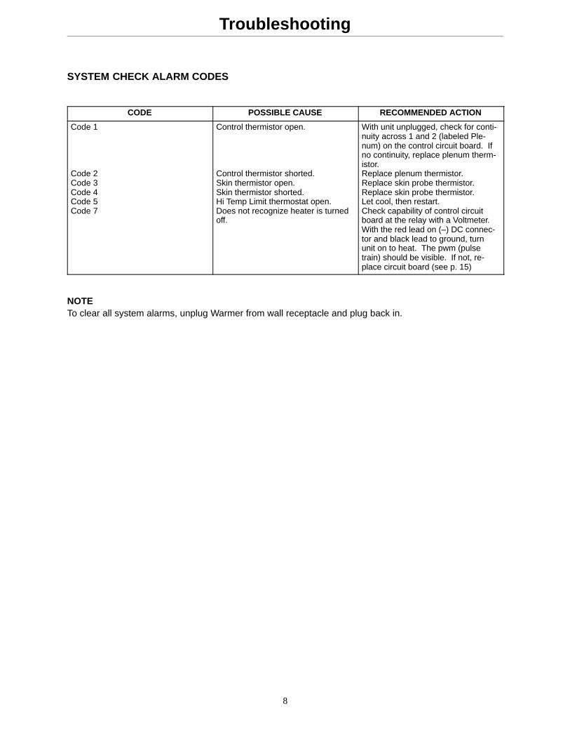
SYSTEM CHECK ALARM CODES
CODE POSSIBLE CAUSE RECOMMENDED ACTION
Code 1 Code 2Code 3Code 4Code 5Code 7
Control thermistor open. Control thermistor shorted.Skin thermistor open.Skin thermistor shorted.Hi Temp Limit thermostat open.Does not recognize heater is turnedoff.
With unit unplugged, check for conti-nuity across 1 and 2 (labeled Ple-num) on the control circuit board. Ifno continuity, replace plenum therm-istor.Replace plenum thermistor.Replace skin probe thermistor.Replace skin probe thermistor.Let cool, then restart.Check capability of control circuitboard at the relay with a Voltmeter.With the red lead on (–) DC connec-tor and black lead to ground, turnunit on to heat. The pwm (pulsetrain) should be visible. If not, re-place circuit board (see p. 15)
NOTETo clear all system alarms, unplug Warmer from wall receptacle and plug back in.
9
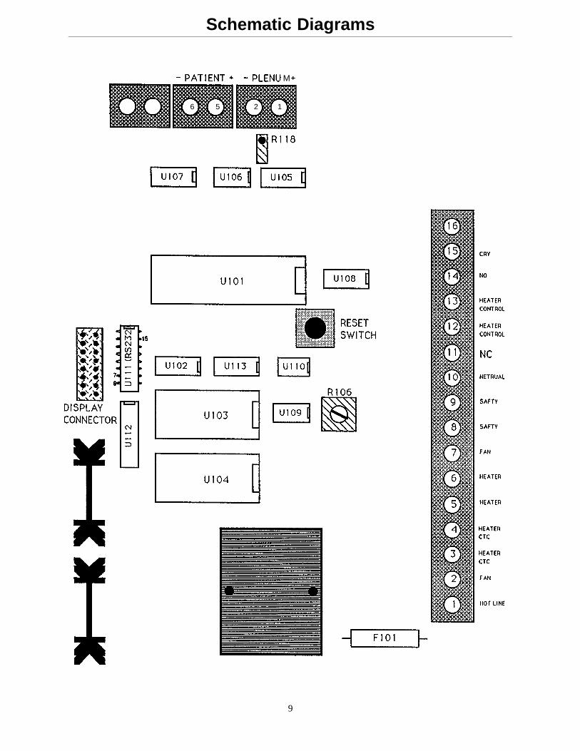
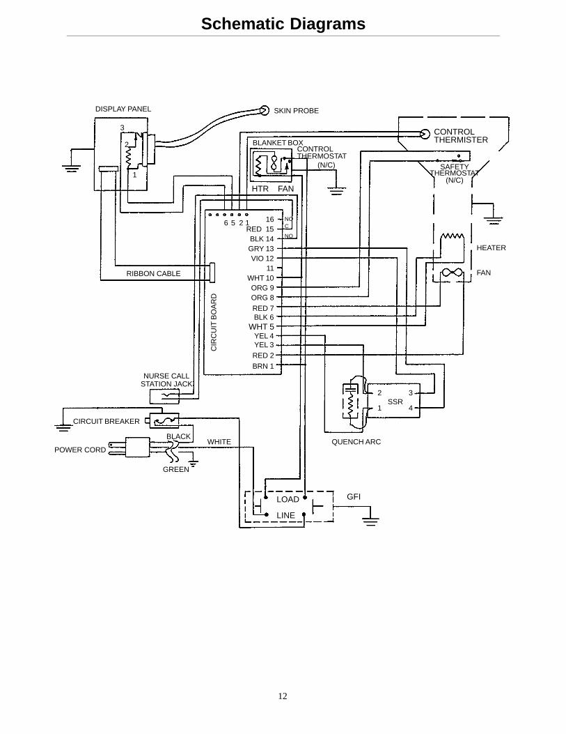
Schematic Diagrams
1256
M
10
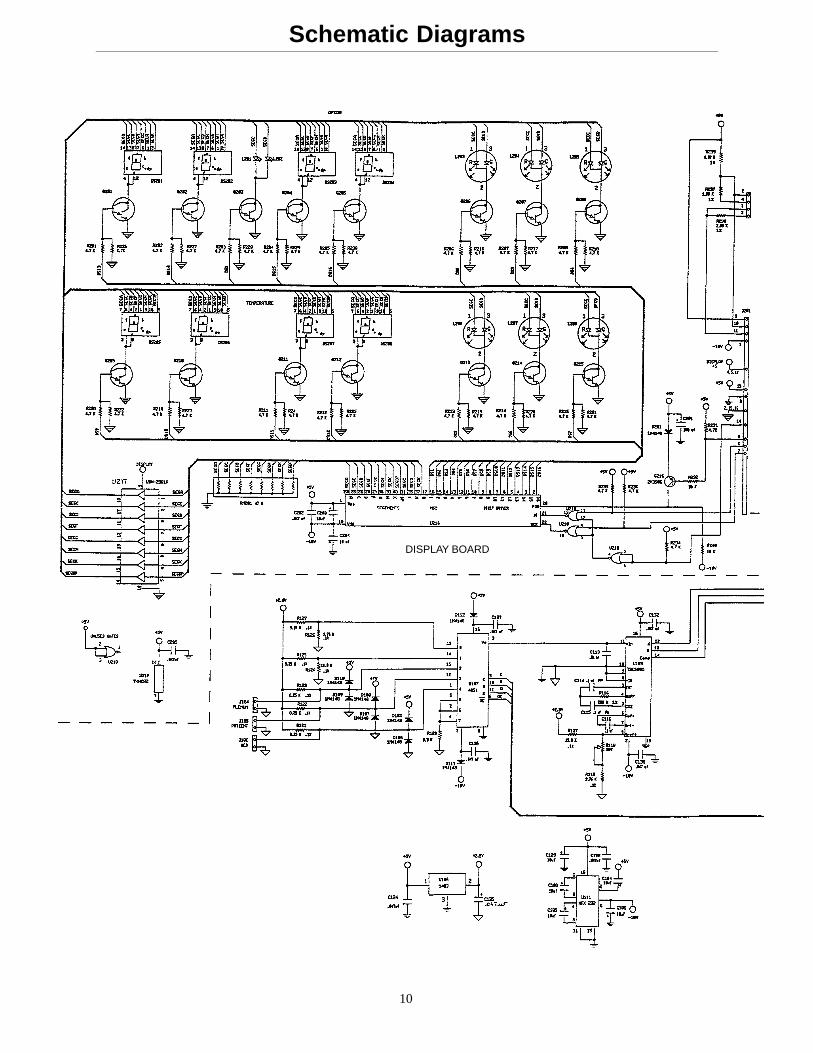
Schematic Diagrams
DISPLAY BOARD
11
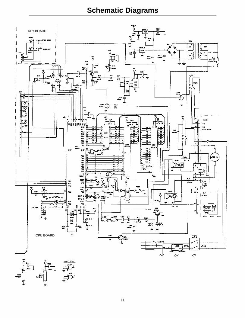
Schematic Diagrams
CPU BOARD
KEY BOARD
12
Schematic Diagrams
DISPLAY PANEL
3
2
1
SKIN PROBE
RIBBON CABLE
BLANKET BOX
HTR FAN
CONTROLTHERMOSTAT
(N/C)
CONTROLTHERMISTER
SAFETYTHERMOSTAT
(N/C)
HEATER
FAN
QUENCH ARC
2
1
3
4SSR
GFILOAD
LINE
WHITEBLACK
GREEN
POWER CORD
CIRCUIT BREAKER
NURSE CALLSTATION JACK
CIR
CU
IT B
OA
RD
6 5 2 1 16RED 15BLK 14GRY 13VIO 12
11WHT 10ORG 9ORG 8RED 7BLK 6
WHT 5YEL 4YEL 3RED 2BRN 1
NCC
NO
13
Service Information
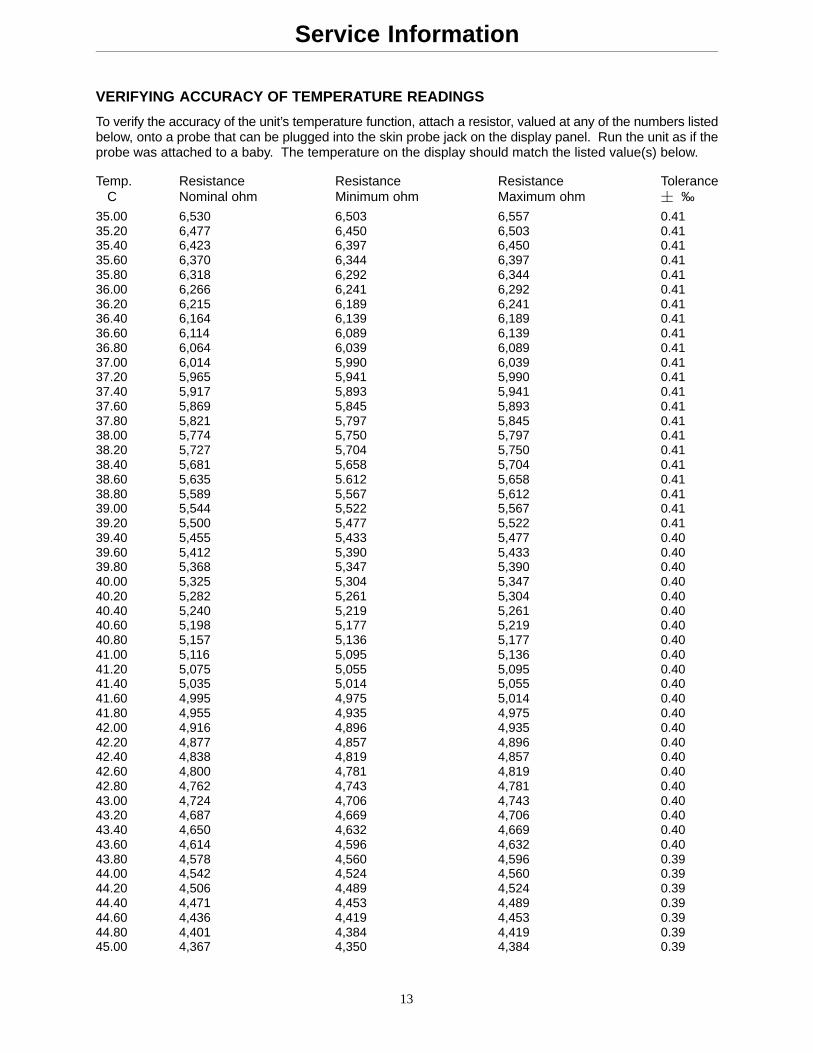
VERIFYING ACCURACY OF TEMPERATURE READINGS
To verify the accuracy of the unit’s temperature function, attach a resistor, valued at any of the numbers listedbelow, onto a probe that can be plugged into the skin probe jack on the display panel. Run the unit as if theprobe was attached to a baby. The temperature on the display should match the listed value(s) below.
Temp. Resistance Resistance Resistance Tolerance C Nominal ohm Minimum ohm Maximum ohm � ‰
35.00 6,530 6,503 6,557 0.4135.20 6,477 6,450 6,503 0.4135.40 6,423 6,397 6,450 0.4135.60 6,370 6,344 6,397 0.4135.80 6,318 6,292 6,344 0.4136.00 6,266 6,241 6,292 0.4136.20 6,215 6,189 6,241 0.4136.40 6,164 6,139 6,189 0.4136.60 6,114 6,089 6,139 0.4136.80 6,064 6,039 6,089 0.4137.00 6,014 5,990 6,039 0.4137.20 5,965 5,941 5,990 0.4137.40 5,917 5,893 5,941 0.4137.60 5,869 5,845 5,893 0.4137.80 5,821 5,797 5,845 0.4138.00 5,774 5,750 5,797 0.4138.20 5,727 5,704 5,750 0.4138.40 5,681 5,658 5,704 0.4138.60 5,635 5.612 5,658 0.4138.80 5,589 5,567 5,612 0.4139.00 5,544 5,522 5,567 0.4139.20 5,500 5,477 5,522 0.4139.40 5,455 5,433 5,477 0.4039.60 5,412 5,390 5,433 0.4039.80 5,368 5,347 5,390 0.4040.00 5,325 5,304 5,347 0.4040.20 5,282 5,261 5,304 0.4040.40 5,240 5,219 5,261 0.4040.60 5,198 5,177 5,219 0.4040.80 5,157 5,136 5,177 0.4041.00 5,116 5,095 5,136 0.4041.20 5,075 5,055 5,095 0.4041.40 5,035 5,014 5,055 0.4041.60 4,995 4,975 5,014 0.4041.80 4,955 4,935 4,975 0.4042.00 4,916 4,896 4,935 0.4042.20 4,877 4,857 4,896 0.4042.40 4,838 4,819 4,857 0.4042.60 4,800 4,781 4,819 0.4042.80 4,762 4,743 4,781 0.4043.00 4,724 4,706 4,743 0.4043.20 4,687 4,669 4,706 0.4043.40 4,650 4,632 4,669 0.4043.60 4,614 4,596 4,632 0.4043.80 4,578 4,560 4,596 0.3944.00 4,542 4,524 4,560 0.3944.20 4,506 4,489 4,524 0.3944.40 4,471 4,453 4,489 0.3944.60 4,436 4,419 4,453 0.3944.80 4,401 4,384 4,419 0.3945.00 4,367 4,350 4,384 0.39
14
Service Information
MEMBRANE SWITCH REPLACEMENT
MEMBRANE SWITCH KIT #88–1132–22–00
Required Tools:
Phillips Screwdriver 3/8 End Wrench
Replacement Procedure:
1. Unplug the power cord from the wall receptacle.
2. Remove the eight screws holding the display housing to the back cover.
3. Tilt the circuit board toward you until you can unplug the membrane switch connector and ribbon cable.Remove the display circuit board from the housing.
4. Remove the mounting nut on the skin probe receptacle.
CAUTION
Membrane switches are fragile. Never depress a membrane dome unless the switch is lying on a flat, firmsurface. Doing otherwise will cause the switch to fail eventually. When applying a new membrane switch,lay it down evenly; do not roll it down. Once a membrane switch has been peeled back, it cannot be reused.
5. Install skin probe receptacle into replacement housing and tighten the mounting nut.
6. Plug the ribbon cable and membrane switch connectors into the display circuit board.
7. Realign the housing with the back panel and replace the eight screws to hold the housing in place. Be surethe cables are not pinched.
8. Plug the power cord into a properly grounded hospital grade wall receptacle and test all functions a mini-mum of three times. Check electrical safety in conformance with specified hospital requirements (leakagecurrent, ground continuity, etc.) before returning Warmer to service.
DISPLAY CIRCUIT BOARD REPLACEMENT
DISPLAY CIRCUIT BOARD #88–1131–20–00
Required Tools:
Phillips Screwdriver 3/8 End Wrench
Replacement Procedure:
1. Unplug the power cord from the wall receptacle.
2. Remove the eight screws holding the display housing to the back cover.
3. Tilt the circuit board toward you until you can unplug the membrane switch connector and ribbon cable.Remove the defective display circuit board from the housing.
4. Install replacement circuit board and plug the ribbon cable and membrane switch connectors into the circuitboard.
5. Realign the housing with the back panel and replace the eight screws to hold the housing in place. Be surethe cables are not pinched.
6. Plug the power cord into a properly grounded hospital grade wall receptacle and test all functions a mini-mum of three times. Check electrical safety in conformance with specified hospital requirements (leakagecurrent, ground continuity, etc.) before returning Warmer to service.
15
Service Information
CONTROL CIRCUIT BOARD REPLACEMENT
CONTROL CIRCUIT BOARD #88–1131–21–00
Required Tools:
Phillips Screwdriver 5/16 Nut Driver Standard Screwdriver
Replacement Procedure:
To remove the defective control circuit board:
1. Unplug the power cord from the wall receptacle and remove the Warmer back panel.
CAUTION
Use of a static wrist band is required.
2. Loosen all the screws on the terminal strip and remove all wires and the quench arc (on older models).
3. Unplug the display panel ribbon cable and disconnect the patient and plenum thermistor leads.
4. Remove the four 6–32 hex nuts and remove the circuit board.
5. Place replacement circuit board over pem studs and secure with the four 6–32 hex nuts.
6. Reconnect the plenum and patient thermistor leads and plug in the display panel ribbon cable.
7. Reconnect wires and quench arc to the terminal strip (see schematic p. 9 for proper sequence). Tightenall the screws securely.
8. Ensure all cables and electrical connections are secure and replace the back panel.
9. Plug the power cord into a properly grounded hospital grade wall receptacle and test all functions a mini-mum of three times. Check electrical safety in conformance with specified hospital requirements (leakagecurrent, ground continuity, etc.) before returning Warmer to service.
FAN REPLACEMENT
FAN #88–1131–17–00
Required Tools:
Phillips Screwdriver Standard Screwdriver
Replacement Procedure:
1. Unplug the power cord from the wall receptacle, remove the Warmer back panel and the shield around theplenum.
2. Disconnect the lead wires of the fan.
3. Remove the cover on the right side of the plenum and slide the fan assembly out.
4. Slide the replacement fan on the track until it is even with the edge of the plenum. Replace the right sidecover.
5. Reattach the fan leads and replace the shield around the plenum.
6. Ensure all cables and electrical connections are secure and all shields are replaced. Replace the backpanel.
7. Plug the power cord into a properly grounded hospital grade wall receptacle and cycle at least three times(Heat On). Check electrical safety in conformance with specified hospital requirements (leakage current,ground continuity, etc.) before returning Warmer to service.
16
Service Information
HEATER REPLACEMENT
HEATER #88–1131–18–00
Required Tools:
Phillips Screwdriver Standard ScrewdriverNeedle Nose Pliers
Replacement Procedure:
1. Unplug the power cord from the wall receptacle, remove the Warmer back panel and the shields aroundthe plenum.
2. Disconnect the lead wires of the fan.
3. Remove the cover on the right side of the plenum.
4. Counting from the bottom of the terminal strip, loosen screws #5 and #6 (white and black wires) on theterminal strip and remove heater lead wires (cut tie wrap as needed).
5. Remove wire strain relief bushing.
6. Remove the defective heater from the plenum.
7. Install replacement heater, feed wires through strain relief plenum hole and reinstall strain relief bushing.
8. Reattach the heater leads to the terminal strip and tighten the screws. Reinstall tie wrap as needed. Reat-tach the fan leads.
9. Ensure all electrical connections are secure and the plenum cover and shields are replaced. Replace theback panel.
10. Plug the power cord into a properly grounded hospital grade wall receptacle and cycle a minimum of threetimes (Heat On). Check electrical safety in conformance with specified hospital requirements (leakage cur-rent, ground continuity, etc.) before returning Warmer to service.
THERMOSTAT SWITCH REPLACEMENT
HEATER #88–1131–18–00
Required Tools:
Phillips Screwdriver Standard Screwdriver
Replacement Procedure:
1. Unplug the power cord from the wall receptacle and remove the Warmer back panel.
2. The thermostat is located on the upper right slope of the plenum. Pull off the flag connectors and removethe two screws and the defective thermostat.
3. Attach the replacement thermostat with the two screws and attach the flag connectors.
4. Reattach the back panel and plug the power cord into a properly grounded hospital grade wall receptacle.Cycle a minimum of three times (Heat On). Check electrical safety in conformance with specified hospitalrequirements (leakage current, ground continuity, etc.) before returning Warmer to service.
17
Service Information
BLANKET WARMER HEATER/FAN REPLACEMENT
BLANKET WARMER HEATER #88–1131–88–00BLANKET WARMER FAN KIT #88–1131–86–00
Required Tools:
Phillips Screwdriver 3/8 Nut Driver Blade ScrewdriverDrill with 1/8” Drill Bit 11/32 Nut Driver Wire Cutters
Replacement Procedure:
1. Unplug the power cord from the wall receptacle.
2. Open the door of the blanket warmer, lift up the bottom tray and remove the three wood screws.
3. Disconnect the brown and blue heater wires from the circuit board and ground wires on counterweight ter-minal.
4. Cut wire ties holding wires together and disconnect wire restraint clip.
5. Remove the blanket box from the cabinet and drill out the four pop rivets on the rear panel. Remove therear panel.
6. Remove the four screws in the perforated screen.
7. Remove the four screws holding the heater panel. Fold down the panel and remove the wire terminal nuts.
8. Remove the two mounting screws holding the heater to the panel. If replacing the fan, remove the mountingscrews.
9. Attach replacement heater/fan to panel with the two mounting screws.
10. Attach the wire leads and replace the panel into the blanket warmer.
11. Replace the perforated screen.
12. Plug the power cord into a properly grounded hospital grade wall receptacle. Wait 5–10 minutes and checkfor warmth in the blanket compartment.
13. Check electrical safety in conformance with specified hospital requirements (leakage current, ground conti-nuity, etc.) before returning Warmer to service.
BLANKET WARMER THERMOSTAT SWITCH REPLACEMENT
BLANKET WARMER THERMOSTAT SWITCH #88–1131–87–00
Required Tools:
Phillips Screwdriver 3/8 Nut Driver Blade ScrewdriverDrill with 1/8” Drill Bit 11/32 Nut Driver Wire Cutters
Replacement Procedure:
Follow the same procedure as above except:
1. Replace step 7 with:Remove the two screws holding the thermostat switch and pull off the flag connectors.
2. Delete step 8 and step 9.
3. Replace step 10 with:Attach the flag terminals to the switch and install with the two screws.
18
Service Information
GROUND FAULT INTERRUPT REPLACEMENT
GFI KIT #88–1131–80–00
Required Tools:
Phillips Screwdriver
Replacement Procedure:
1. Unplug the power cord from the wall receptacle.
2. Remove Warmer back panel. Remove leads from both ”line” and ”load” sides of the GFI.
3. Remove the defective GFI.
4. Secure line connections (power cord) to replacement GFI, noting polarity of hook–up.
5. Secure the load side wires to the PC board.
6. Install the replacement GFI.
7. Plug the power cord into a properly grounded hospital grade wall receptacle. Press test button on GFI.If switch trips, press reset button.
8. Reinstall Warmer back panel and return Warmer to service.
TEMPERATURE DISPLAY SELECTION
Required Tools:
Phillips Screwdriver Tweezers or Needle–Nosed Pliers
Procedure:
1. Unplug the power cord from the wall receptacle.
2. Remove Warmer back panel.
3. The temperature selector plug is located directly above the largest integrated circuit chip on the uppermiddle section of the circuit board
4. To change from centigrade to Fahrenheit, slide the cap off the center and right pins and relocate it on thecenter and left pins. Do not change Hertz jumper.
5. Reinstall Warmer back panel and return Warmer to service.
NOTEThis same procedure is used to change the frequency selector from 60 to 50 HZ for international use. Thefrequency 50/60 Hz plug/cap is to the right of the temperature C/F plug/cap.
19
Service Information
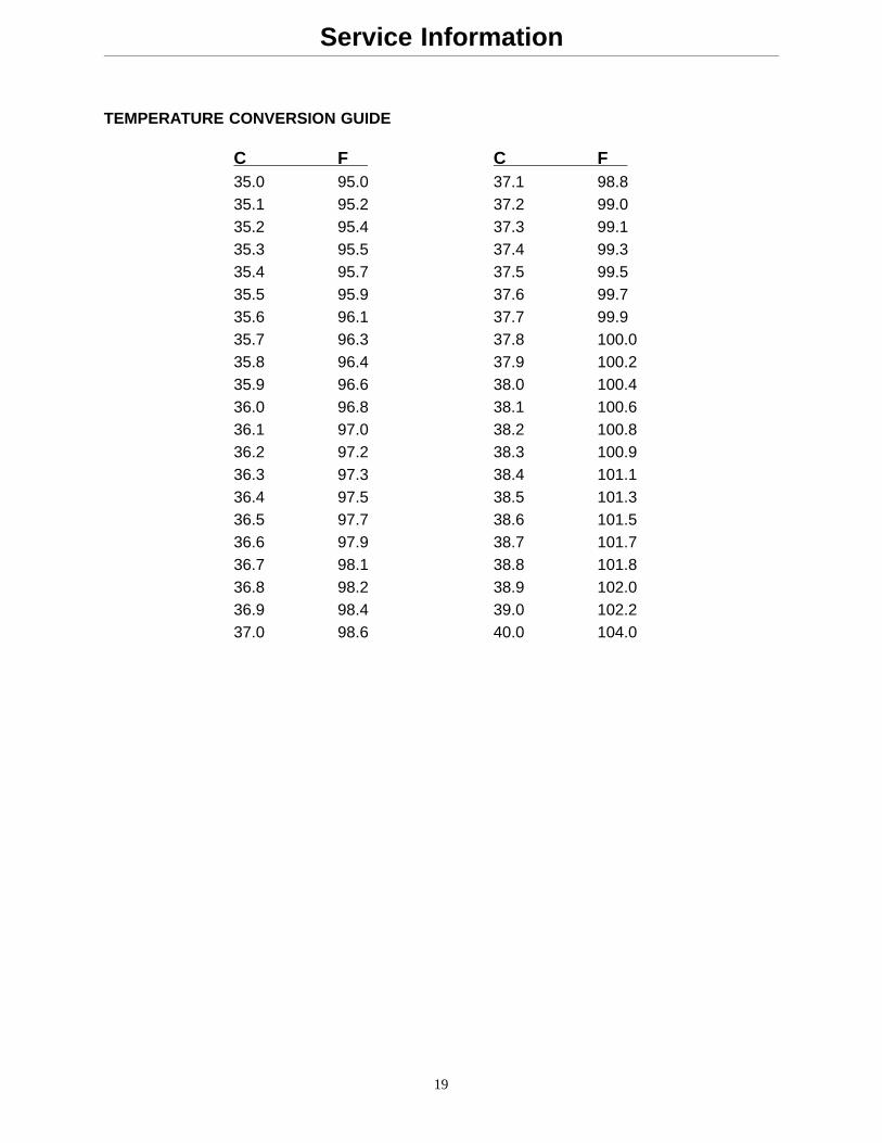
TEMPERATURE CONVERSION GUIDE
C F C F 35.0 95.0 37.1 98.835.1 95.2 37.2 99.035.2 95.4 37.3 99.135.3 95.5 37.4 99.335.4 95.7 37.5 99.535.5 95.9 37.6 99.735.6 96.1 37.7 99.935.7 96.3 37.8 100.035.8 96.4 37.9 100.235.9 96.6 38.0 100.436.0 96.8 38.1 100.636.1 97.0 38.2 100.836.2 97.2 38.3 100.936.3 97.3 38.4 101.136.4 97.5 38.5 101.336.5 97.7 38.6 101.536.6 97.9 38.7 101.736.7 98.1 38.8 101.836.8 98.2 38.9 102.036.9 98.4 39.0 102.237.0 98.6 40.0 104.0
Service Information
19.1
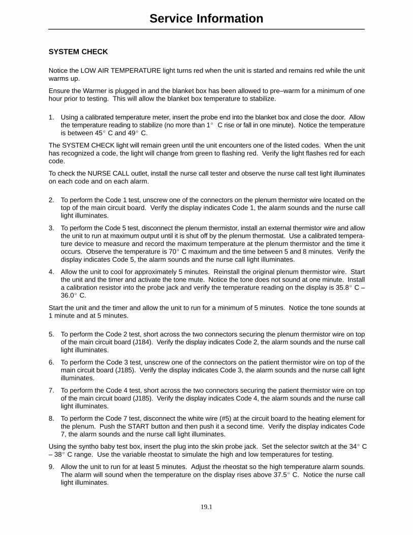
SYSTEM CHECK
Notice the LOW AIR TEMPERATURE light turns red when the unit is started and remains red while the unitwarms up.
Ensure the Warmer is plugged in and the blanket box has been allowed to pre–warm for a minimum of onehour prior to testing. This will allow the blanket box temperature to stabilize.
1. Using a calibrated temperature meter, insert the probe end into the blanket box and close the door. Allowthe temperature reading to stabilize (no more than 1� C rise or fall in one minute). Notice the temperatureis between 45� C and 49� C.
The SYSTEM CHECK light will remain green until the unit encounters one of the listed codes. When the unithas recognized a code, the light will change from green to flashing red. Verify the light flashes red for eachcode.
To check the NURSE CALL outlet, install the nurse call tester and observe the nurse call test light illuminateson each code and on each alarm.
2. To perform the Code 1 test, unscrew one of the connectors on the plenum thermistor wire located on thetop of the main circuit board. Verify the display indicates Code 1, the alarm sounds and the nurse calllight illuminates.
3. To perform the Code 5 test, disconnect the plenum thermistor, install an external thermistor wire and allowthe unit to run at maximum output until it is shut off by the plenum thermostat. Use a calibrated tempera-ture device to measure and record the maximum temperature at the plenum thermistor and the time itoccurs. Observe the temperature is 70� C maximum and the time between 5 and 8 minutes. Verify thedisplay indicates Code 5, the alarm sounds and the nurse call light illuminates.
4. Allow the unit to cool for approximately 5 minutes. Reinstall the original plenum thermistor wire. Startthe unit and the timer and activate the tone mute. Notice the tone does not sound at one minute. Installa calibration resistor into the probe jack and verify the temperature reading on the display is 35.8� C –36.0� C.
Start the unit and the timer and allow the unit to run for a minimum of 5 minutes. Notice the tone sounds at1 minute and at 5 minutes.
5. To perform the Code 2 test, short across the two connectors securing the plenum thermistor wire on topof the main circuit board (J184). Verify the display indicates Code 2, the alarm sounds and the nurse calllight illuminates.
6. To perform the Code 3 test, unscrew one of the connectors on the patient thermistor wire on top of themain circuit board (J185). Verify the display indicates Code 3, the alarm sounds and the nurse call lightilluminates.
7. To perform the Code 4 test, short across the two connectors securing the patient thermistor wire on topof the main circuit board (J185). Verify the display indicates Code 4, the alarm sounds and the nurse calllight illuminates.
8. To perform the Code 7 test, disconnect the white wire (#5) at the circuit board to the heating element forthe plenum. Push the START button and then push it a second time. Verify the display indicates Code7, the alarm sounds and the nurse call light illuminates.
Using the syntho baby test box, insert the plug into the skin probe jack. Set the selector switch at the 34� C– 38� C range. Use the variable rheostat to simulate the high and low temperatures for testing.
9. Allow the unit to run for at least 5 minutes. Adjust the rheostat so the high temperature alarm sounds.The alarm will sound when the temperature on the display rises above 37.5� C. Notice the nurse calllight illuminates.
Service Information
19.2
SYSTEM CHECK (CONTINUED)
The HIGH INFANT TEMPERATURE light will remain green until the syntho baby rheostat is adjusted to raisethe display temperature above 37.5� C. The light must then begin flashing red. The alarm will stop whenthe temperature drops below 37.6� C. Repeat to verify the alarm mute button will silence the alarm.
10. Adjust the rheostat so the low temperature alarm sounds. The alarm will sound when the temperatureon the display drops below 35.5� C. Notice the nurse call light illuminates.
The LOW INFANT TEMPERATURE light will remain green until the syntho baby rheostat is adjusted to lowerthe display temperature below 35.5� C. The light must then begin flashing red. The alarm will stop whenthe temperature rises above 35.4� C. Repeat to verify the alarm mute button will silence the alarm.
11. To check the PROBE OUT light, unplug the syntho baby which will cause the light to change from greento red. Verify it functions properly.
12. To check the skin probe, install it in the receptacle, insert the sensor end in a thin plastic bag with a cali-brated thermocouple and immerse the bag in a warm cup of water. To verify the temperature, comparethe temperature display on the thermocouple to the temperature display on the unit. The differenceshould be no more than .10� C.
20
Field Replacement Parts
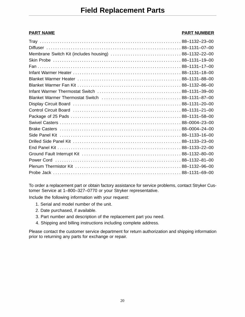
PART NAME PART NUMBER
Tray 88–1132–23–00. . . . . . . . . . . . . . . . . . . . . . . . . . . . . . . . . . . . . . . . . . . . . . . . . . . . . . . . . . . . . . . . Diffuser 88–1131–07–00. . . . . . . . . . . . . . . . . . . . . . . . . . . . . . . . . . . . . . . . . . . . . . . . . . . . . . . . . . . . . Membrane Switch Kit (includes housing) 88–1132–22–00. . . . . . . . . . . . . . . . . . . . . . . . . . . . . . . . Skin Probe 88–1131–19–00. . . . . . . . . . . . . . . . . . . . . . . . . . . . . . . . . . . . . . . . . . . . . . . . . . . . . . . . . . Fan 88–1131–17–00. . . . . . . . . . . . . . . . . . . . . . . . . . . . . . . . . . . . . . . . . . . . . . . . . . . . . . . . . . . . . . . . . Infant Warmer Heater 88–1131–18–00. . . . . . . . . . . . . . . . . . . . . . . . . . . . . . . . . . . . . . . . . . . . . . . . . Blanket Warmer Heater 88–1131–88–00. . . . . . . . . . . . . . . . . . . . . . . . . . . . . . . . . . . . . . . . . . . . . . . Blanket Warmer Fan Kit 88–1132–86–00. . . . . . . . . . . . . . . . . . . . . . . . . . . . . . . . . . . . . . . . . . . . . . . Infant Warmer Thermostat Switch 88–1131–39–00. . . . . . . . . . . . . . . . . . . . . . . . . . . . . . . . . . . . . . Blanket Warmer Thermostat Switch 88–1131–87–00. . . . . . . . . . . . . . . . . . . . . . . . . . . . . . . . . . . . Display Circuit Board 88–1131–20–00. . . . . . . . . . . . . . . . . . . . . . . . . . . . . . . . . . . . . . . . . . . . . . . . . Control Circuit Board 88–1131–21–00. . . . . . . . . . . . . . . . . . . . . . . . . . . . . . . . . . . . . . . . . . . . . . . . . Package of 25 Pads 88–1131–58–00. . . . . . . . . . . . . . . . . . . . . . . . . . . . . . . . . . . . . . . . . . . . . . . . . . Swivel Casters 88–0004–23–00. . . . . . . . . . . . . . . . . . . . . . . . . . . . . . . . . . . . . . . . . . . . . . . . . . . . . . . Brake Casters 88–0004–24–00. . . . . . . . . . . . . . . . . . . . . . . . . . . . . . . . . . . . . . . . . . . . . . . . . . . . . . . Side Panel Kit 88–1133–16–00. . . . . . . . . . . . . . . . . . . . . . . . . . . . . . . . . . . . . . . . . . . . . . . . . . . . . . . Drilled Side Panel Kit 88–1133–23–00. . . . . . . . . . . . . . . . . . . . . . . . . . . . . . . . . . . . . . . . . . . . . . . . . End Panel Kit 88–1133–22–00. . . . . . . . . . . . . . . . . . . . . . . . . . . . . . . . . . . . . . . . . . . . . . . . . . . . . . . . Ground Fault Interrupt Kit 88–1132–80–00. . . . . . . . . . . . . . . . . . . . . . . . . . . . . . . . . . . . . . . . . . . . . Power Cord 88–1132–81–00. . . . . . . . . . . . . . . . . . . . . . . . . . . . . . . . . . . . . . . . . . . . . . . . . . . . . . . . . Plenum Thermistor Kit 88–1132–96–00. . . . . . . . . . . . . . . . . . . . . . . . . . . . . . . . . . . . . . . . . . . . . . . . Probe Jack 88–1131–69–00. . . . . . . . . . . . . . . . . . . . . . . . . . . . . . . . . . . . . . . . . . . . . . . . . . . . . . . . . .
To order a replacement part or obtain factory assistance for service problems, contact Stryker Cus-tomer Service at 1–800–327–0770 or your Stryker representative.
Include the following information with your request:
1. Serial and model number of the unit. 2. Date purchased, if available. 3. Part number and description of the replacement part you need. 4. Shipping and billing instructions including complete address.
Please contact the customer service department for return authorization and shipping informationprior to returning any parts for exchange or repair.

21
Notes
22
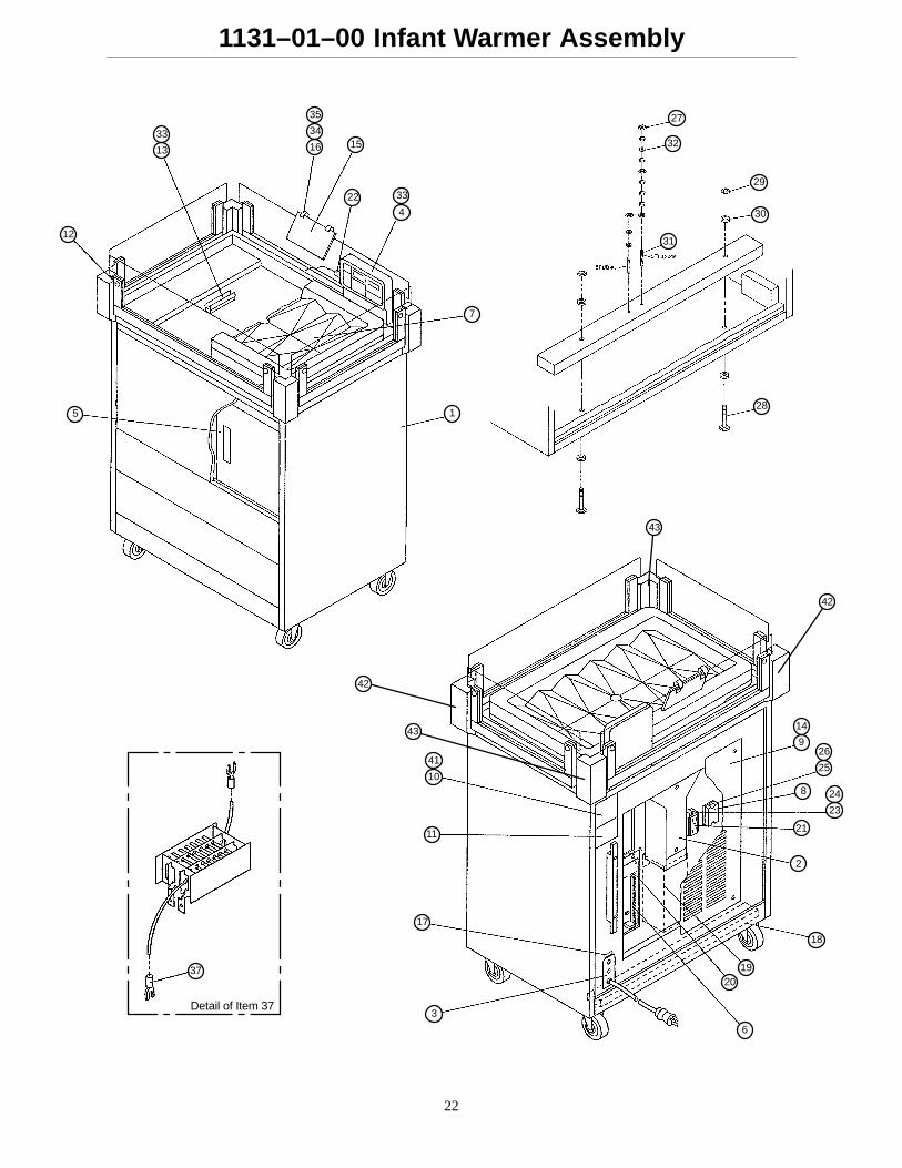
1131–01–00 Infant Warmer Assembly
27
32
31
29
30
285 1
7
4
3322
1516
34
35
33
13
12
6
2019
18
2
21
23
248
25
269
14
10
41
11
17
3
37
Detail of Item 37
42
43
43
42
23
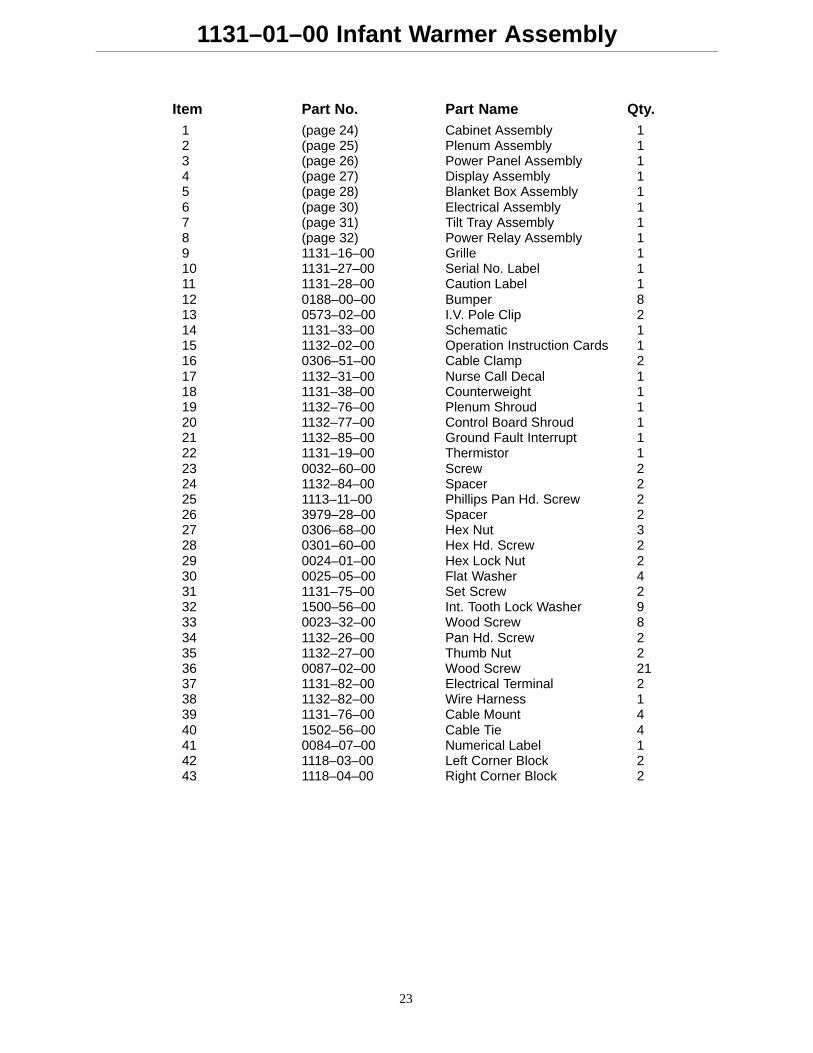
1131–01–00 Infant Warmer Assembly
Item Part No. Part Name Qty.1 (page 24) Cabinet Assembly 12 (page 25) Plenum Assembly 13 (page 26) Power Panel Assembly 14 (page 27) Display Assembly 15 (page 28) Blanket Box Assembly 16 (page 30) Electrical Assembly 17 (page 31) Tilt Tray Assembly 18 (page 32) Power Relay Assembly 19 1131–16–00 Grille 110 1131–27–00 Serial No. Label 111 1131–28–00 Caution Label 112 0188–00–00 Bumper 813 0573–02–00 I.V. Pole Clip 214 1131–33–00 Schematic 115 1132–02–00 Operation Instruction Cards 116 0306–51–00 Cable Clamp 217 1132–31–00 Nurse Call Decal 118 1131–38–00 Counterweight 119 1132–76–00 Plenum Shroud 120 1132–77–00 Control Board Shroud 121 1132–85–00 Ground Fault Interrupt 122 1131–19–00 Thermistor 123 0032–60–00 Screw 224 1132–84–00 Spacer 225 1113–11–00 Phillips Pan Hd. Screw 226 3979–28–00 Spacer 227 0306–68–00 Hex Nut 328 0301–60–00 Hex Hd. Screw 229 0024–01–00 Hex Lock Nut 230 0025–05–00 Flat Washer 431 1131–75–00 Set Screw 232 1500–56–00 Int. Tooth Lock Washer 933 0023–32–00 Wood Screw 834 1132–26–00 Pan Hd. Screw 235 1132–27–00 Thumb Nut 236 0087–02–00 Wood Screw 2137 1131–82–00 Electrical Terminal 238 1132–82–00 Wire Harness 139 1131–76–00 Cable Mount 440 1502–56–00 Cable Tie 441 0084–07–00 Numerical Label 142 1118–03–00 Left Corner Block 243 1118–04–00 Right Corner Block 2
24
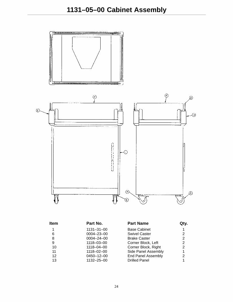
1131–05–00 Cabinet Assembly
Item Part No. Part Name Qty.1 1131–31–00 Base Cabinet 16 0004–23–00 Swivel Caster 28 0004–24–00 Brake Caster 29 1118–03–00 Corner Block, Left 210 1118–04–00 Corner Block, Right 211 1118–02–00 Side Panel Assembly 112 0450–12–00 End Panel Assembly 213 1132–25–00 Drilled Panel 1
25
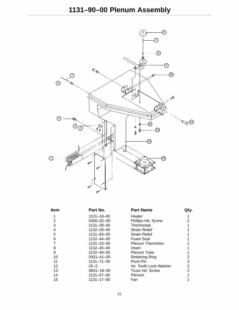
1131–90–00 Plenum Assembly
6
7
8
9
10
1112
13
14
151
23
4
5
7
Item Part No. Part Name Qty.1 1131–18–00 Heater 12 0306–02–00 Phillips Hd. Screw 23 1131–39–00 Thermostat 14 1132–28–00 Strain Relief 15 1131–83–00 Strain Relief 16 1132–44–00 Foam Seal 17 1131–23–00 Plenum Thermistor 18 1132–45–00 Insert 19 1132–49–00 Plenum Tube 110 0301–41–00 Retaining Ring 211 1131–71–00 Pivot Pin 212 25–2 Int. Tooth Lock Washer 213 0831–18–00 Truss Hd. Screw 214 1131–57–00 Plenum 115 1131–17–00 Fan 1
26
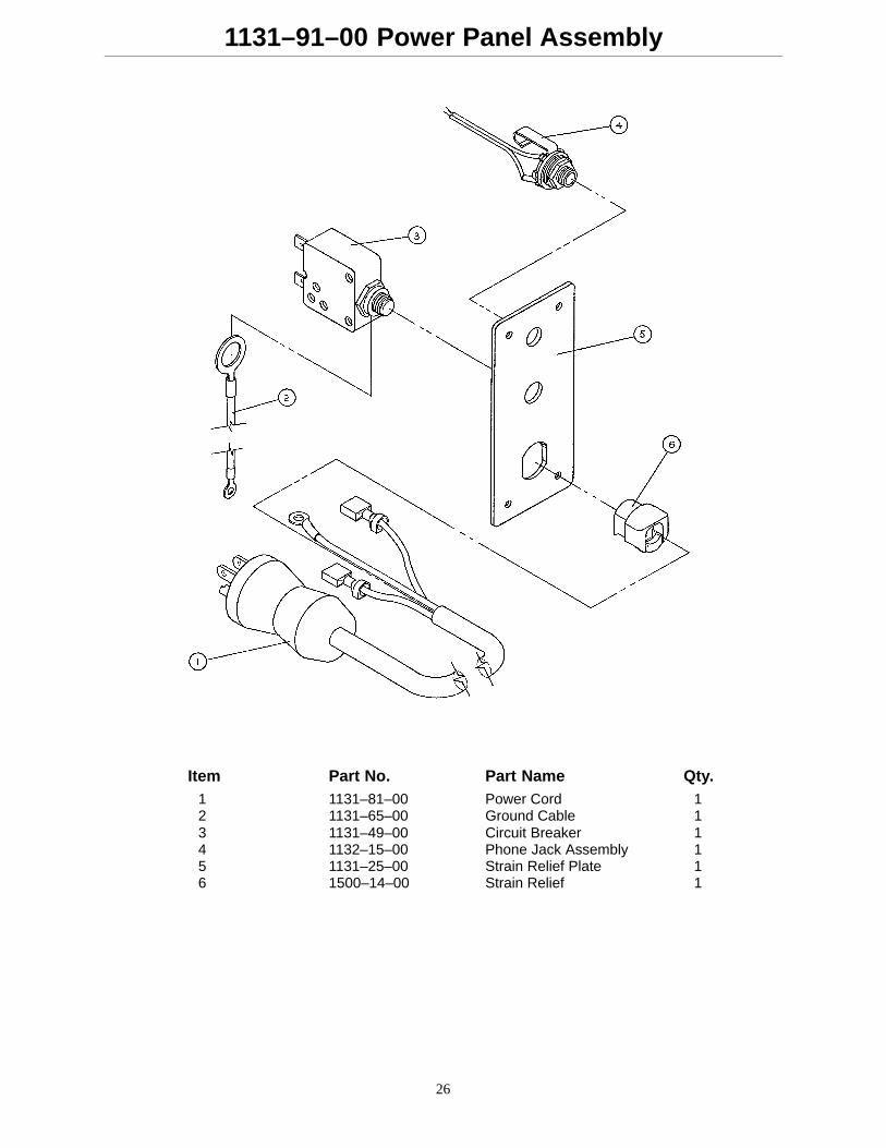
1131–91–00 Power Panel Assembly
Item Part No. Part Name Qty.1 1131–81–00 Power Cord 12 1131–65–00 Ground Cable 13 1131–49–00 Circuit Breaker 14 1132–15–00 Phone Jack Assembly 15 1131–25–00 Strain Relief Plate 16 1500–14–00 Strain Relief 1
27
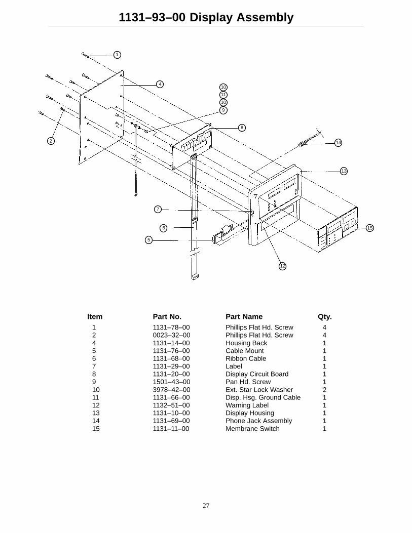
1131–93–00 Display Assembly
14
13
15
12
5
6
7
2
1
410
11
10
9
8
Item Part No. Part Name Qty.1 1131–78–00 Phillips Flat Hd. Screw 42 0023–32–00 Phillips Flat Hd. Screw 44 1131–14–00 Housing Back 15 1131–76–00 Cable Mount 16 1131–68–00 Ribbon Cable 17 1131–29–00 Label 18 1131–20–00 Display Circuit Board 19 1501–43–00 Pan Hd. Screw 110 3978–42–00 Ext. Star Lock Washer 211 1131–66–00 Disp. Hsg. Ground Cable 112 1132–51–00 Warning Label 113 1131–10–00 Display Housing 114 1131–69–00 Phone Jack Assembly 115 1131–11–00 Membrane Switch 1
28
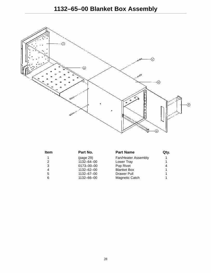
1132–65–00 Blanket Box Assembly
Item Part No. Part Name Qty.1 (page 29) Fan/Heater Assembly 12 1132–64–00 Lower Tray 13 0173–00–00 Pop Rivet 44 1132–62–00 Blanket Box 15 1132–67–00 Drawer Pull 16 1132–66–00 Magnetic Catch 1
29
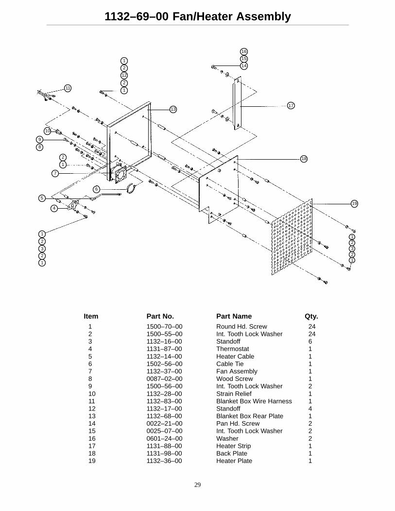
1132–69–00 Fan/Heater Assembly
12321
19
18
17
14
15
16
13
1
2
12
2
1
11
10
9
8
2
1
7
5
6
4
1
2
3
2
1
Item Part No. Part Name Qty.1 1500–70–00 Round Hd. Screw 242 1500–55–00 Int. Tooth Lock Washer 243 1132–16–00 Standoff 64 1131–87–00 Thermostat 15 1132–14–00 Heater Cable 16 1502–56–00 Cable Tie 17 1132–37–00 Fan Assembly 18 0087–02–00 Wood Screw 19 1500–56–00 Int. Tooth Lock Washer 210 1132–28–00 Strain Relief 111 1132–83–00 Blanket Box Wire Harness 112 1132–17–00 Standoff 413 1132–68–00 Blanket Box Rear Plate 114 0022–21–00 Pan Hd. Screw 215 0025–07–00 Int. Tooth Lock Washer 216 0601–24–00 Washer 217 1131–88–00 Heater Strip 118 1131–98–00 Back Plate 119 1132–36–00 Heater Plate 1
30
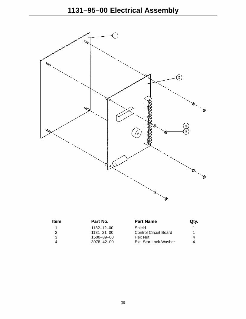
1131–95–00 Electrical Assembly
Item Part No. Part Name Qty.1 1132–12–00 Shield 12 1131–21–00 Control Circuit Board 13 1500–39–00 Hex Nut 44 3978–42–00 Ext. Star Lock Washer 4
31
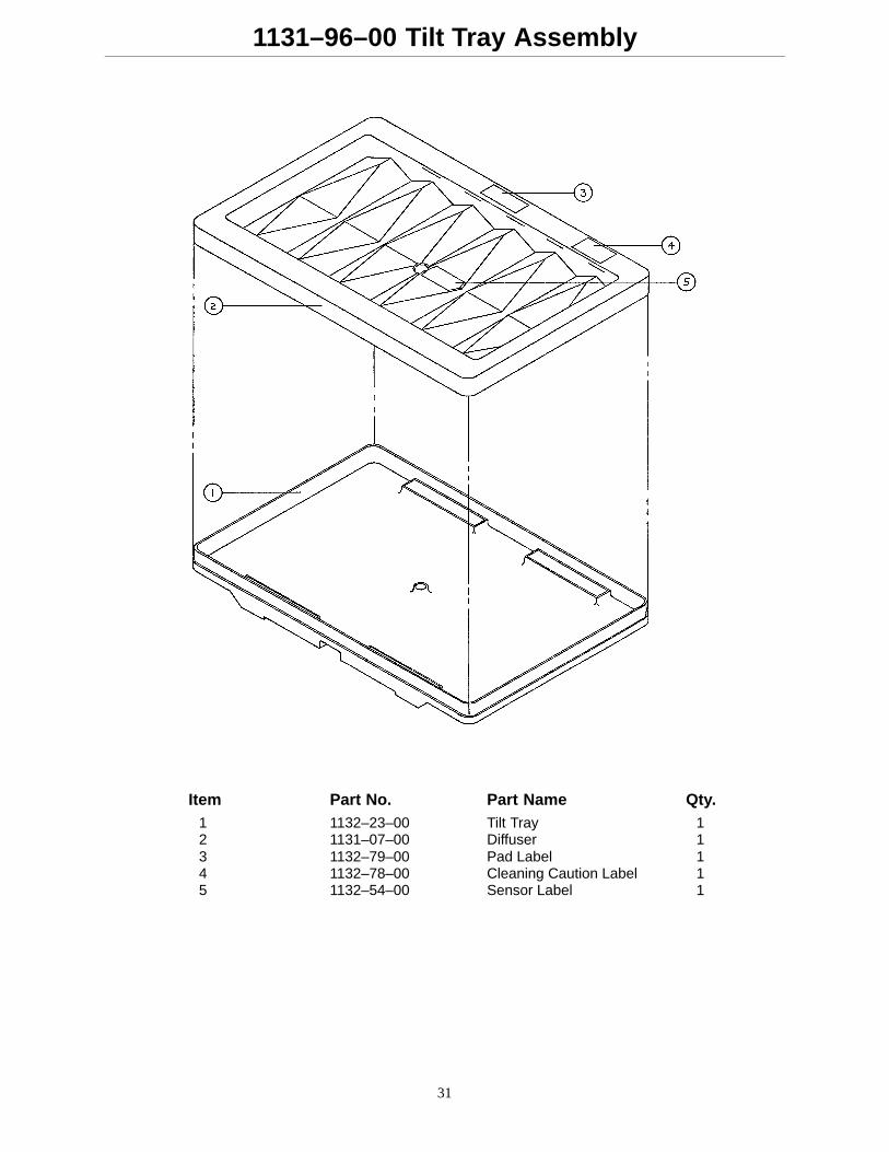
1131–96–00 Tilt Tray Assembly
Item Part No. Part Name Qty.1 1132–23–00 Tilt Tray 12 1131–07–00 Diffuser 13 1132–79–00 Pad Label 14 1132–78–00 Cleaning Caution Label 15 1132–54–00 Sensor Label 1
32
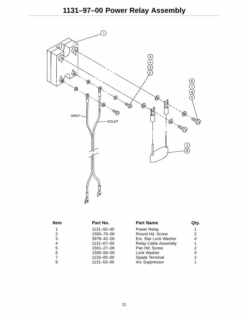
1131–97–00 Power Relay Assembly
Item Part No. Part Name Qty.1 1131–50–00 Power Relay 12 1500–70–00 Round Hd. Screw 23 3978–42–00 Ext. Star Lock Washer 44 1131–67–00 Relay Cable Assembly 15 1501–27–00 Pan Hd. Screw 26 1500–56–00 Lock Washer 47 1133–00–00 Spade Terminal 28 1131–53–00 Arc Suppressor 1
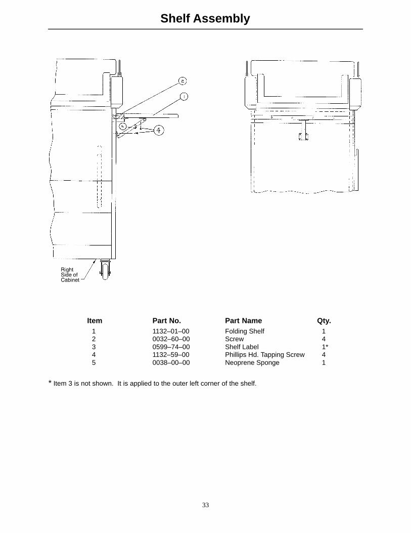
Shelf Assembly
33
Item Part No. Part Name Qty.1 1132–01–00 Folding Shelf 12 0032–60–00 Screw 43 0599–74–00 Shelf Label 1*4 1132–59–00 Phillips Hd. Tapping Screw 45 0038–00–00 Neoprene Sponge 1
* Item 3 is not shown. It is applied to the outer left corner of the shelf.
34
Warranty
Limited Warranty:
Stryker Medical Division warrants to the original purchaser that its products should be free from defects inmaterial and workmanship for a period of one (1) year after date of delivery. Stryker’s obligation under thiswarranty is expressly limited to supplying replacement parts and labor for, or replacing, at its option, any prod-uct which is, in the sole discretion of Stryker, found to be defective. Stryker warrants to the original purchaserthat the frame and welds on its beds will be free from structural defects for as long as the original purchaserowns the bed. If requested by Stryker, products or parts for which a warranty claim is made shall be returnedprepaid to Stryker factory. Any improper use or any alteration or repair by others in such manner as in Stryk-er’s judgement affects the product materially and adversely shall void this warranty. No employee or repre-sentative of Stryker is authorized to change this warranty in any way.
This statement constitutes Stryker’s entire warranty with respect to the aforesaid equipment. STRYKERMAKES NO OTHER WARRANTY OR REPRESENTATION, EITHER EXPRESSED OR IMPLIED, EXCEPTAS SET FORTH HEREIN. THERE IS NO WARRANTY OF MERCHANTABILITY AND THERE ARE NOWARRANTIES OF FITNESS FOR ANY PARTICULAR PURPOSE. IN NO EVENT SHALL STRYKER BELIABLE HEREUNDER FOR INCIDENTAL OR CONSEQUENTIAL DAMAGES ARISING FROM OR IN ANYMANNER RELATED TO SALES OR USE OF ANY SUCH EQUIPMENT.
To Obtain Parts and Service:
Stryker products are supported by a nationwide network of dedicated Stryker Field Service Representatives.These representatives are factory trained, available locally, and carry a substantial spare parts inventory tominimize repair time. Simply call your local representative, or call Stryker Customer Service at (800)327–0770.
Supplemental Warranty Coverage:
Stryker has developed a comprehensive program of extended warranty options designed to keep your equip-ment operating at peak performance at the same time it eliminates unexpected costs. We recommend thatthese programs be activated before the expiration of the new product warranty to eliminate the potential ofadditional equipment upgrade charges. Stryker offers the following Supplemental Warranties:
Extended (Parts and Labor)
� All replacement parts (excluding mattresses and consumable items)
� Labor and travel for all scheduled and unscheduled calls
� Annual Preventive Maintenance Inspections and repairs
� JCAHO paperwork for preventive maintenance
� Priority Emergency Service
Standard (Labor Only):
� Labor and travel for all scheduled and unscheduled calls
� Annual Preventive Maintenance Inspections and repairs
� JCAHO paperwork for preventive maintenance
� Priority Emergency Service
Basic (Parts Only):
� All replacement parts (excluding mattresses and consumable items)
� Priority Emergency Service
Please call your local representative, or call (800) 327–0770 for further information
35
Warranty
Return Authorization:
Merchandise cannot be returned without approval from the Stryker Customer Service Department. An autho-rization number will be provided which must be printed on the returned merchandise. Stryker reserves theright to charge shipping and restocking fees on returned items.
SPECIAL, MODIFIED, OR DISCONTINUED ITEMS NOT SUBJECT TO RETURN.
Damaged Merchandise:
ICC Regulations require that claims for damaged merchandise must be made with the carrier within fifteen(15) days of receipt of merchandise. DO NOT ACCEPT DAMAGED SHIPMENTS UNLESS SUCH DAMAGEIS NOTED ON THE DELIVERY RECEIPT AT THE TIME OF RECEIPT. Upon prompt notification, Strykerwill file a freight claim with the appropriate carrier for damages incurred. Claim will be limited in amount tothe actual replacement cost. In the event that this information is not received by Stryker within the fifteen(15) day period following the delivery of the merchandise, or the damage was not noted on the delivery receiptat the time of receipt, the customer will be responsible for payment of the original invoice in full.
Claims for any short shipment must be made within thirty (30) days of invoice.
International Warranty Clause:
This warranty reflects U.S. domestic policy. Warranty outside the U.S. may vary by country. Please contactyour local Stryker representative for additional information.

DH 7/98 8815–033–500 REV A
European Representative
Stryker France Phone: 33148632290BP 50040–95946 Roissy Ch. de Gaulle Fax: 33148632175Cedex–France
6300 Sprinkle Road, Kalamazoo, MI 49001–9799 (800) 327–0770