Embed Size (px)
Citation preview
Inexpensive Immersive ProjectionNancy P. Y. Yuen∗
California State University East BayWilliam C. Thibault†
California State University East Bay
ABSTRACT
Most projector-based immersive displays have numerous problemsrelating to complexity, space, and cost. We present a technique forrendering perspectively correct images using a casual arrangementof a projector, a mirror and a display surface.
Our technique renders an arbitrarily wide field of view using anefficient GPU-based single-pass rendering algorithm. The render-ing algorithm is preceded by a one-time camera-based geometriccorrection calibration step. As we will describe, this technique canbe implemented with inexpensive, commodity hardware and usingreadily available display surfaces. Thus, this technique enables im-mersive projection systems to be used in casual locations, such as aclassroom or even in the home.
Keywords: display algorithms, viewing algorithms, camera cali-bration, projector-camera systems
Index Terms: I.3.3 [Computing Methodologies]: ComputerGraphics—Picture/Image Generation; I.4.1 [Image Processing andComputer Vision]: Digitization and Image Capture—Camera Cali-bration
1 INTRODUCTION
Projectors are often used to create a large field of view in an im-mersive environment. Such environments have many useful appli-cation in entertainment, production, and education. However, exist-ing projector-based immersive environments have numerous com-plexity, space, and cost problems. They often require an expen-sive screen, and expensive projectors and lenses to function. Also,precise and time-consuming positioning of the projector is oftenneeded. These factors drive the cost of immersive environmentsbeyond the reach of many institutions.
Our goal is to build an immersive projection system that meetsthese requirements: uses minimal, affordable hardware; takes ad-vantage of existing surfaces for display; requires minimal setup andconfiguration; produces a large field of view, greater than 180 de-grees; requires only a casual arrangement of system components;avoids determining display surface geometry; supports real-time in-teraction.
This paper describes an inexpensive immersive projection sys-tem built using commodity parts to display images on diffuse sur-faces. It uses a one-time camera-based geometric calibration stepto determine how the final image should be displayed. It does notrequire the computation of projector intrinsics or extrinsics, andfunctions for any arrangement of projector and display surface ge-ometry. The result is a system that eliminates the usual cost andcomplexity associated with projector-based immersive display en-vironments. Further, our approach uses a GPU-based single-passrendering algorithm suitable for real-time interaction. Existing ap-plications can be ported to use this approach with minimal modifi-cation.
∗e-mail:[email protected]†e-mail:[email protected]
2 PRIOR WORK
Projectors are useful for creating large displays on surfaces of anyshape. However, to surround the viewer with imagery, 3D com-puter graphics rendering algorithms must address the limitations ofperspective projection. Wide fields-of-view create distortions whenusing perspective, and even the widest perspective viewing volumesmust have a field-of-view of less than 180 degrees.
The usual approach is to use a cubemap [11] to store thepanoramic image prior to mapping it to the display surface. Eachface in a cubemap is created with a separate rendering pass over thedataset. In each pass, the viewing and projection transformationsare set to that particular face. GPUs that support multiple rendertargets can create a cubemap with a single pass over the geometry.Cubemaps are attractive as they have simple, fast hardware imple-mentations. However, most cubemap texture filtering implementa-tions fail to correctly handle edges of the cube.
Traditional ”high-end immersive projection VR” systems suchas the CAVE [10] [9] feature high-resolution rear-projection, stereo,and head-tracking. These systems are effective for creating a senseof immersion that fills the viewer’s visual field while allowing free-dom of motion. Although effective, these systems are expensive interms of hardware and physical space.
Small, inexpensive dome displays can be created using a singleprojector and a spherical mirror, such as those sold for safety orsecurity applications [7]. These inexpensive mirrors are far fromperfect, however. Simple geodesic domes can be easily constructedfrom common materials such as cardboard [14]. Software writtenassuming a specific geometry for the projector, mirror, and domescreen is becoming available [4].
Cameras are increasingly used to calibrate projected displays[17] [16] [5] [15]. These typically use homographies (projec-tive transformations) to model the projection process, which limitstheir use to planar display surfaces. Another approach to the useof camera-based calibration is Raskar’s two-pass algorithm [17],which first renders the desired image to a texture, and in a secondpass renders a model of the display surface that is textured with theimage, using texture coordinates derived from the camera calibra-tion.
The direct use of camera-projector correspondences to performthis real time warp [19] [8] [13] has the advantage that non-lineardistortions in the projectors are handled. Also, screens of any shapeare supported, as display surface geometry is not needed. Commer-cial systems using this approach have begun to appear [2] [3]. Thetechnique creates an image that appears perspectively-correct froma specific viewing location. The camera is placed at this locationduring calibration. Any effects due to screen geometry are capturedin the resulting map from camera to projector coordinates. Thus,the general technique of calibrating with a camera at the intendedviewing position can support screens of arbitrary shape, given thatthe result will only appear correct from the intended viewpoint.
Other systems have used a vertex program to compute non-standard projections. Raskar [18] used a vertex program to computea warp for a quadric display shape.
Our system differs from previous ones by allowing the creationof the projected immersive imagery with a single pass over the inputgeometry. We do not attempt to compute a warp and we do not usea cubemap. We avoid the resampling errors possible when using the
237
IEEE Virtual Reality 20088-12 March, Reno, Nevada, USA978-1-4244-1972-2/08/$25.00 ©2008 IEEE
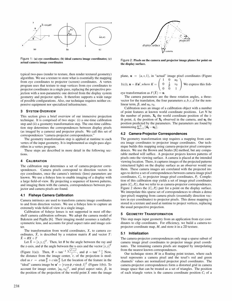
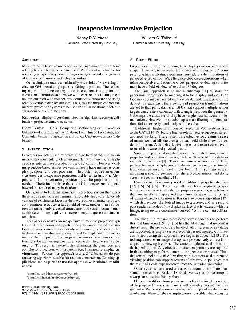
Figure 1: (a) eye coordinates; (b) ideal camera image coordinates; (c)actual camera image coordinates
typical two-pass (render to texture, then render textured geometry)algorithm. We use a texture to store what is essentially the mappingfrom eye coordinates to projector (screen) coordinates. A vertexprogram uses that texture to map vertices from eye coordinates toprojector coordinates in a single pass, replacing the perspective pro-jection with a non-parametric one derived from the display systemgeometry and projector optics. It therefore supports a wide rangeof possible configurations. Also, our technique requires neither ex-pensive equipment nor specialized infrastructure.
3 SYSTEM OVERVIEW
This section gives a brief overview of our immersive projectiontechnique. It is comprised of two steps: (i) a one-time calibrationstep and (ii) a geometry transformation step. The one-time calibra-tion step determines the correspondences between display pixels(as imaged by a camera) and projector pixels. We call this set ofcorrespondences ”camera-projector correspondences.”
The geometry transformation step is applied at runtime to eachvertex of the input geometry. It is implemented as single-pass algo-rithm in a vertex program.
These steps are described in more detail in the following sec-tions.
4 CALIBRATION
The calibration step determines a set of camera-projector corre-spondences. Camera pixels correspond to direction vectors ineye coordinates, once the camera’s intrinsic (lens) parameters areknown. We use a fisheye lens to enable imaging of a display witha large field-of-view. By projecting a sequence of known patterns,and imaging them with the camera, correspondences between pro-jector and camera pixels are found.
4.1 Fisheye Camera CalibrationCamera intrinsics are used to transform camera image coordinatesto and from direction vectors. We use a fisheye lens to capture anextremely wide field-of-view in a single image.
Calibration of fisheye lenses is not supported in most off-the-shelf camera calibration software. We adopt the camera model ofBakstein and Pajdla [6]. Their imaging model assumes a radially-symmetric lens, and accounts for pixel aspect ratio and image cen-ter.
The transformation from world coordinates, X , to camera co-ordinates, X , is described by a rotation matrix R and vector T :X = RX +T
Let X = [x,y,z]T . Then, let θ be the angle between the ray andthe z-axis, and φ the angle between the x-axis and the vector [x,y]T
(Figure 1(a)). Then, θ = tan−1√
x2+y2
z , and φ = tan−1 yx Now,
the distance from the image center, r, of the projection is mod-eled as r = a tan θ
b + csin θ
d Let the location of the feature in the“ideal” camera image be u′ = [r cosφ ,r sinφ ,1]T (Figure 1(b)). Toaccount for image center, [u0,v0]T , and pixel aspect ratio, β , inthe position of the projection of the world point X onto the image
Figure 2: Pixels on the camera and projector image planes for point onthe display surface.
plane, u = (u,v,1), in “actual” image pixel coordinates (Figure
1(c)), u = Ku′,where K =
1 0 u00 1
βv0
0 0 1
We express this fish-
eye transformation as F(X) = u.The camera parameters are the three rotation angles, a three-
vector for the translation, the four parameters a,b,c,d for the non-linear term, β , and u0,v0.
Calibration uses an image of a calibration object with a numberof point features at known world coordinate positions. Let N bethe number of points, Xi the world coordinate position of the i-th point, ui the position of Xi observed in the camera, and ui theposition predicted by the parameters. The parameters are found byminimizing ∑
Ni=1 ||ui−ui||.
4.2 Camera-Projector CorrespondencesThe geometry transformation step requires a mapping from cam-era image coordinates to projector image coordinates. Our tech-nique builds this mapping using camera-projector pixel correspon-dences. We use the Brown and Seales [8] method, but any compa-rable method will suffice. A projector projects known patterns ofpixels onto the viewing surface. A camera is placed at the intendedviewing location. There, it captures images of the projected patterns(structured light) on the display surface as an observer would seethem. These camera images are correlated with the projected im-ages to derive a set of correspondences between camera image pixelcoordinates, Ci, to projector image pixel coordinates, Pi. Comple-tion of this calibration step yields a set of image pixel coordinatespairs (Ci,Pi), that we refer to as camera-projector correspondences.Figure 2 shows the (Ci,Pi) pair for a point on the display surface.We interpolate this sparse set of correspondences to obtain a dense(per-pixel) mapping from camera pixels (essentially direction vec-tors in eye coordinates) to projector pixels. This dense mapping isstored in a texture and used at runtime to project vertices, replacingthe usual perspective projection.
5 GEOMETRY TRANSFORMATION
This step maps input geometry from an application from eye coor-dinates to clip coordinates. For efficiency, we build a camera-to-projector coordinate map, M, and store it in a 2D texture.
5.1 InitializationThe camera-projector correspondences only map a sparse subset ofcamera image pixel coordinates to projector image pixel coordi-nates. The remaining camera pixels are mapped by interpolatingfrom the nearest known correspondences.
Our technique stores M in a floating point texture, where eachtexel represents a camera pixel and the texel’s red and greenchannels’ values are normalized projector pixel coordinates. Thecamera-projector correspondences form a distorted grid in cameraimage space that can be treated as a set of triangles. The positionof each triangle vertex is the camera coordinate position Ci of a
238
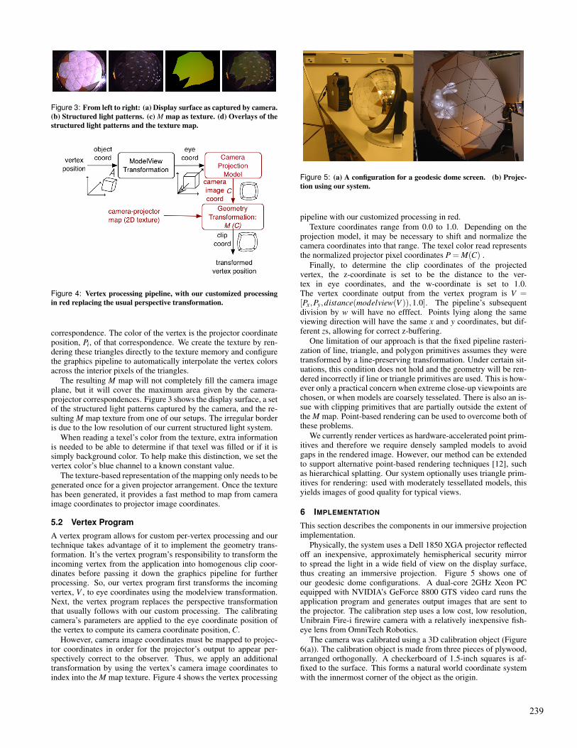
Figure 3: From left to right: (a) Display surface as captured by camera.(b) Structured light patterns. (c) M map as texture. (d) Overlays of thestructured light patterns and the texture map.
Figure 4: Vertex processing pipeline, with our customized processingin red replacing the usual perspective transformation.
correspondence. The color of the vertex is the projector coordinateposition, Pi, of that correspondence. We create the texture by ren-dering these triangles directly to the texture memory and configurethe graphics pipeline to automatically interpolate the vertex colorsacross the interior pixels of the triangles.
The resulting M map will not completely fill the camera imageplane, but it will cover the maximum area given by the camera-projector correspondences. Figure 3 shows the display surface, a setof the structured light patterns captured by the camera, and the re-sulting M map texture from one of our setups. The irregular borderis due to the low resolution of our current structured light system.
When reading a texel’s color from the texture, extra informationis needed to be able to determine if that texel was filled or if it issimply background color. To help make this distinction, we set thevertex color’s blue channel to a known constant value.
The texture-based representation of the mapping only needs to begenerated once for a given projector arrangement. Once the texturehas been generated, it provides a fast method to map from cameraimage coordinates to projector image coordinates.
5.2 Vertex Program
A vertex program allows for custom per-vertex processing and ourtechnique takes advantage of it to implement the geometry trans-formation. It’s the vertex program’s responsibility to transform theincoming vertex from the application into homogenous clip coor-dinates before passing it down the graphics pipeline for furtherprocessing. So, our vertex program first transforms the incomingvertex, V , to eye coordinates using the modelview transformation.Next, the vertex program replaces the perspective transformationthat usually follows with our custom processing. The calibratingcamera’s parameters are applied to the eye coordinate position ofthe vertex to compute its camera coordinate position, C.
However, camera image coordinates must be mapped to projec-tor coordinates in order for the projector’s output to appear per-spectively correct to the observer. Thus, we apply an additionaltransformation by using the vertex’s camera image coordinates toindex into the M map texture. Figure 4 shows the vertex processing
Figure 5: (a) A configuration for a geodesic dome screen. (b) Projec-tion using our system.
pipeline with our customized processing in red.Texture coordinates range from 0.0 to 1.0. Depending on the
projection model, it may be necessary to shift and normalize thecamera coordinates into that range. The texel color read representsthe normalized projector pixel coordinates P = M(C) .
Finally, to determine the clip coordinates of the projectedvertex, the z-coordinate is set to be the distance to the ver-tex in eye coordinates, and the w-coordinate is set to 1.0.The vertex coordinate output from the vertex program is V =[Px,Py,distance(modelview(V )),1.0]. The pipeline’s subsequentdivision by w will have no efffect. Points lying along the sameviewing direction will have the same x and y coordinates, but dif-ferent zs, allowing for correct z-buffering.
One limitation of our approach is that the fixed pipeline rasteri-zation of line, triangle, and polygon primitives assumes they weretransformed by a line-preserving transformation. Under certain sit-uations, this condition does not hold and the geometry will be ren-dered incorrectly if line or triangle primitives are used. This is how-ever only a practical concern when extreme close-up viewpoints arechosen, or when models are coarsely tesselated. There is also an is-sue with clipping primitives that are partially outside the extent ofthe M map. Point-based rendering can be used to overcome both ofthese problems.
We currently render vertices as hardware-accelerated point prim-itives and therefore we require densely sampled models to avoidgaps in the rendered image. However, our method can be extendedto support alternative point-based rendering techniques [12], suchas hierarchical splatting. Our system optionally uses triangle prim-itives for rendering: used with moderately tessellated models, thisyields images of good quality for typical views.
6 IMPLEMENTATION
This section describes the components in our immersive projectionimplementation.
Physically, the system uses a Dell 1850 XGA projector reflectedoff an inexpensive, approximately hemispherical security mirrorto spread the light in a wide field of view on the display surface,thus creating an immersive projection. Figure 5 shows one ofour geodesic dome configurations. A dual-core 2GHz Xeon PCequipped with NVIDIA’s GeForce 8800 GTS video card runs theapplication program and generates output images that are sent tothe projector. The calibration step uses a low cost, low resolution,Unibrain Fire-i firewire camera with a relatively inexpensive fish-eye lens from OmniTech Robotics.
The camera was calibrated using a 3D calibration object (Figure6(a)). The calibration object is made from three pieces of plywood,arranged orthogonally. A checkerboard of 1.5-inch squares is af-fixed to the surface. This forms a natural world coordinate systemwith the innermost corner of the object as the origin.
239
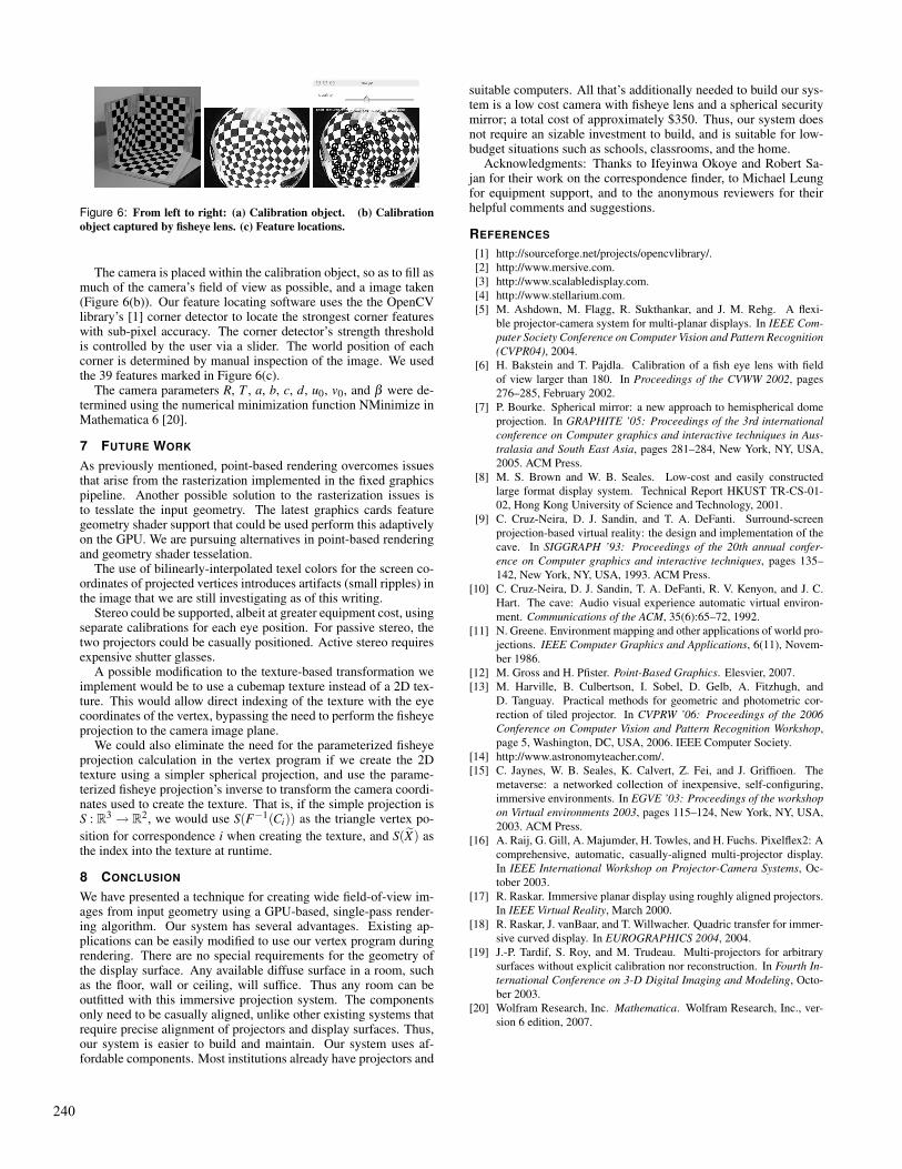
Figure 6: From left to right: (a) Calibration object. (b) Calibrationobject captured by fisheye lens. (c) Feature locations.
The camera is placed within the calibration object, so as to fill asmuch of the camera’s field of view as possible, and a image taken(Figure 6(b)). Our feature locating software uses the the OpenCVlibrary’s [1] corner detector to locate the strongest corner featureswith sub-pixel accuracy. The corner detector’s strength thresholdis controlled by the user via a slider. The world position of eachcorner is determined by manual inspection of the image. We usedthe 39 features marked in Figure 6(c).
The camera parameters R, T , a, b, c, d, u0, v0, and β were de-termined using the numerical minimization function NMinimize inMathematica 6 [20].
7 FUTURE WORK
As previously mentioned, point-based rendering overcomes issuesthat arise from the rasterization implemented in the fixed graphicspipeline. Another possible solution to the rasterization issues isto tesslate the input geometry. The latest graphics cards featuregeometry shader support that could be used perform this adaptivelyon the GPU. We are pursuing alternatives in point-based renderingand geometry shader tesselation.
The use of bilinearly-interpolated texel colors for the screen co-ordinates of projected vertices introduces artifacts (small ripples) inthe image that we are still investigating as of this writing.
Stereo could be supported, albeit at greater equipment cost, usingseparate calibrations for each eye position. For passive stereo, thetwo projectors could be casually positioned. Active stereo requiresexpensive shutter glasses.
A possible modification to the texture-based transformation weimplement would be to use a cubemap texture instead of a 2D tex-ture. This would allow direct indexing of the texture with the eyecoordinates of the vertex, bypassing the need to perform the fisheyeprojection to the camera image plane.
We could also eliminate the need for the parameterized fisheyeprojection calculation in the vertex program if we create the 2Dtexture using a simpler spherical projection, and use the parame-terized fisheye projection’s inverse to transform the camera coordi-nates used to create the texture. That is, if the simple projection isS : R3 → R2, we would use S(F−1(Ci)) as the triangle vertex po-sition for correspondence i when creating the texture, and S(X) asthe index into the texture at runtime.
8 CONCLUSION
We have presented a technique for creating wide field-of-view im-ages from input geometry using a GPU-based, single-pass render-ing algorithm. Our system has several advantages. Existing ap-plications can be easily modified to use our vertex program duringrendering. There are no special requirements for the geometry ofthe display surface. Any available diffuse surface in a room, suchas the floor, wall or ceiling, will suffice. Thus any room can beoutfitted with this immersive projection system. The componentsonly need to be casually aligned, unlike other existing systems thatrequire precise alignment of projectors and display surfaces. Thus,our system is easier to build and maintain. Our system uses af-fordable components. Most institutions already have projectors and
suitable computers. All that’s additionally needed to build our sys-tem is a low cost camera with fisheye lens and a spherical securitymirror; a total cost of approximately $350. Thus, our system doesnot require an sizable investment to build, and is suitable for low-budget situations such as schools, classrooms, and the home.
Acknowledgments: Thanks to Ifeyinwa Okoye and Robert Sa-jan for their work on the correspondence finder, to Michael Leungfor equipment support, and to the anonymous reviewers for theirhelpful comments and suggestions.
REFERENCES
[1] http://sourceforge.net/projects/opencvlibrary/.[2] http://www.mersive.com.[3] http://www.scalabledisplay.com.[4] http://www.stellarium.com.[5] M. Ashdown, M. Flagg, R. Sukthankar, and J. M. Rehg. A flexi-
ble projector-camera system for multi-planar displays. In IEEE Com-puter Society Conference on Computer Vision and Pattern Recognition(CVPR04), 2004.
[6] H. Bakstein and T. Pajdla. Calibration of a fish eye lens with fieldof view larger than 180. In Proceedings of the CVWW 2002, pages276–285, February 2002.
[7] P. Bourke. Spherical mirror: a new approach to hemispherical domeprojection. In GRAPHITE ’05: Proceedings of the 3rd internationalconference on Computer graphics and interactive techniques in Aus-tralasia and South East Asia, pages 281–284, New York, NY, USA,2005. ACM Press.
[8] M. S. Brown and W. B. Seales. Low-cost and easily constructedlarge format display system. Technical Report HKUST TR-CS-01-02, Hong Kong University of Science and Technology, 2001.
[9] C. Cruz-Neira, D. J. Sandin, and T. A. DeFanti. Surround-screenprojection-based virtual reality: the design and implementation of thecave. In SIGGRAPH ’93: Proceedings of the 20th annual confer-ence on Computer graphics and interactive techniques, pages 135–142, New York, NY, USA, 1993. ACM Press.
[10] C. Cruz-Neira, D. J. Sandin, T. A. DeFanti, R. V. Kenyon, and J. C.Hart. The cave: Audio visual experience automatic virtual environ-ment. Communications of the ACM, 35(6):65–72, 1992.
[11] N. Greene. Environment mapping and other applications of world pro-jections. IEEE Computer Graphics and Applications, 6(11), Novem-ber 1986.
[12] M. Gross and H. Pfister. Point-Based Graphics. Elesvier, 2007.[13] M. Harville, B. Culbertson, I. Sobel, D. Gelb, A. Fitzhugh, and
D. Tanguay. Practical methods for geometric and photometric cor-rection of tiled projector. In CVPRW ’06: Proceedings of the 2006Conference on Computer Vision and Pattern Recognition Workshop,page 5, Washington, DC, USA, 2006. IEEE Computer Society.
[14] http://www.astronomyteacher.com/.[15] C. Jaynes, W. B. Seales, K. Calvert, Z. Fei, and J. Griffioen. The
metaverse: a networked collection of inexpensive, self-configuring,immersive environments. In EGVE ’03: Proceedings of the workshopon Virtual environments 2003, pages 115–124, New York, NY, USA,2003. ACM Press.
[16] A. Raij, G. Gill, A. Majumder, H. Towles, and H. Fuchs. Pixelflex2: Acomprehensive, automatic, casually-aligned multi-projector display.In IEEE International Workshop on Projector-Camera Systems, Oc-tober 2003.
[17] R. Raskar. Immersive planar display using roughly aligned projectors.In IEEE Virtual Reality, March 2000.
[18] R. Raskar, J. vanBaar, and T. Willwacher. Quadric transfer for immer-sive curved display. In EUROGRAPHICS 2004, 2004.
[19] J.-P. Tardif, S. Roy, and M. Trudeau. Multi-projectors for arbitrarysurfaces without explicit calibration nor reconstruction. In Fourth In-ternational Conference on 3-D Digital Imaging and Modeling, Octo-ber 2003.
[20] Wolfram Research, Inc. Mathematica. Wolfram Research, Inc., ver-sion 6 edition, 2007.
240