Embed Size (px)
Citation preview

INEX BOARDS™
ANY BUILDING • ANY SURFACE • ANYWHERE
INSTALLATION GUIDE

UBIQ is the provider of lightweight sheets for the construction industry. Critically, our products are both low carbon and high performing. For almost a decade UBIQ has been developing the Technology of Low Carbon Fibre Reinforced Engineered Cementitious Composite (ECC) for its application in our range of INEX>BOARDS for the construction industry.
UBIQ’s innovative technology has been developed in Australia with the aim of producing a ‘world’s best’ building board. This aim is now complete.
• ANY BUILDING
• ANY SURFACE
• ANYWHERE
www.ubiq.com.au
Low Carbon UBIQ’s INEX>BOARDS minimise harm to the planet in their production which is undertaken at room temperature. The embodied energy of our board is about 40% to that of comparable fibre cement boards.
Strength UBIQ’s INEX>BOARDS can be manufactured to a bending strength of up to 44MPa. The equilibrium bending strength of our flooring product is 22MPa.
Durability Our boards can be used in all climatic conditions – rain, snow, frost, varying humidities and extreme temperatures.
StabilityOur tests demonstrate that INEX>BOARDS can retain over 80% of the dry strength after 25 soak-dry cycles.
Fire Resistance Our tests demonstrate that INEX>BOARDS are non-combustible, BAL-FZ and FRL 60/60/60 rated. Performance data available on application to UBIQ or at www.ubiq.com.au.
Acoustic Resistance Our tests demonstrate an acoustic attenuation of Rw5 higher than that of standard plasterboard products. At 10mm thickness our boards provide a similarattenuation as 13mm thick sound rated plasterboard.
Impact Resistance INEX>BOARDS offer incredibly high impact resistance – greater than that of traditional compressed fibre cement sheets or impact resistant plasterboards currently on the market.
Water Resistance Our boards have a high level of water resistance and conform to the requirements of the Water Permeability Test.
Radiation Shielding Our tests show enhanced electromagnetic radiation shielding properties.
Healthier Living UBIQ’s INEX>BOARDS promote healthier living. They do not contain asbestos, are non-toxic, provide enhanced breathability and do not support the growth of mould.
All of the above are just some of the benefits of our INEX>BOARDS. It is exciting that all of these improved performance credentials can be found in one low carbon product – in a range of building boards for all surfaces, internal, external; walls, ceilings or floors.2

INEX>FLOOR is a high strength lightweight flooring substrate with tongue and groove (T&G) edges. It can be used for external or internal applications; as a substrate for most finishes such as tiles, vinyl, carpet or timber. INEX>FLOOR can be used in conjunction with floor systems to achieve up to BAL-FZ bushfire compliance.INEX>FLOOR is simplicity itself. A single affordable product for multiple flooring applications.
INEX>FLOORTM
BAL-FZ
3
INEX>WEATHERBOARDTM
Available in 180mm (150mm coverage) or 204mm (172mm coverage) INEX>WEATHERBOARD’s 16mm thickness provides a deep shadow below each board. Suitable for multiple paint and timber stain (rough sawn finish only) applications. Each board is 3 metres long with tongue and grooved ends for off stud jointing. Critically, INEX>WEATHERBOARD comes with a fire rating of FRL 60/60/60 and a bushfire attack level BAL-FZ – and both of these ratings WITHOUT the need for any other fire rated materials.Contact UBIQ or visit www.ubiq.com.au for details of fire rated systems.
FRL 60/60/60
BAL-FZ
A great innovation from UBIQ that delivers a lightweight render substrate board that is suitable for multiple render coating applications. 16mm thick INEX>RENDERBOARD sheets are tongue and grooved to lock together and resist any render cracking over time. They are lightweight at about 33kg each, 2700mm long, 600mm high and can be off stud jointed.Again, INEX>RENDERBOARD comes with a fire rating of FRL 60/60/60 and a bushfire attack level BAL-FZ – and both of these ratings WITHOUT the need for any other fire rated materials.Contact UBIQ or visit www.ubiq.com.au for details of fire rated systems.
INEX>RENDERBOARDTM
FRL 60/60/60
BAL-FZ

TECHNICAL & INSTALLATION SHEET
INEX FLOOR™
WEIGHTAt either approx. 40kg (19mm) or 34kg (16mm) INEX>FLOOR is lighter weight and easy to handle on site.
STORAGEINEX>FLOOR should be stored dry, flat and with all edges protected from damage. We recommend storage undercover and raised from the ground.
HANDLINGWear protective gloves when handling or cutting sheets.
FRAMINGINEX>FLOOR can be fixed to timber or steel joists at a maximum of 600mm centres*. Refer to page 7 for loading properties.
Timber framing must be in accordance with AS 1684 – ‘Residential timber-framed construction’.
Steel framing must be in accordance with AS 3623 – ‘Domestic metal framing’.
Ends or edges without the tongue and groove (butt ends) must be supported by a joist.
Ensure framing is level prior to fitting.
ASSEMBLYINEX>FLOOR can be fitted to a square or staggered layout, but must be staggered for tiled or vinyl finishes. Where waterproofing is required:• Lay rough side up. • Ensure butt joints are over timber/metal joists and have a 2mm gap and are filled with INEX>BOND.• Ensure all T & G joints are filled with INEX>BOND.FIXINGS:Ensure all fixings are located: • 20mm min. from all tongue and grooves;12mm min. from all butt joints• 50mm min. from all corners• Max. 200mm centres along joists.• Run a 6mm bead of INEX>BOND on top of the timber or steel joists below each sheet progressively as they are fixed in place.Ensure framing and INEX>FLOOR boards are clean and dry prior to fitting.
FIXINGS – TIMBER JOISTS – Class 3 Galvanised Fixings or higher*
Screws: 10gx50mm self-embedding countersunk head screws.
FIXINGS – STEEL JOISTS – Class 3 Galvanised Fixings or higher*
Screws: 10gx40mm self-drilling, self-embedding, countersunk head screws.*Class 4 or Stainless Steel screws for sea spray zone in accordance with AS 3566.
FINISHESCLEAR: For specifiers wishing to retain INEX>FLOOR’s raw concrete like appearance*, refer to the COATINGS menu on UBIQ’s website.*Interior application only.
WET AREAS/TILES: Install INEX>FLOOR rough side up. For wet areas such as showers a waterproof membrane is required in accordance with the Building Code of Australia.
CARPET, VINYL or TIMBER: Install INEX>FLOOR with the smooth side up.
GENERAL: Ensure all components and adhesives are compatible with each other.
PRODUCT
SUPPORT
FIXING
APPLICATION
ANY BUILDING • ANY SURFACE • ANYWHERE
NOTE:Even if you do not require a waterproof deck, it is recommended that the deck be made as water-resistant as possible (ie that water penetrations be minimised) as it can lead to damage to the frame such as timber dry rot.
For details relating to waterproof membranes for decks above habitable areas refer to UBIQ’s Technical Department.
*When using INEX>FLOOR as a substrate for floor tiling, if the tile size is greater than 300mm in any direction, floor joist spacing should be no greater than 450mm centres with an approved tile adhesive for both interior and exterior applications.
4

TECHNICAL & INSTALLATION SHEET
FRAMING / ASSEMBLY / FIXINGINEX>FLOOR must be fixed to either timber on light gauge steel framing at a maximum of 600mm centres.* Timber joists must have a minimum width of 45mm to allow for suitable jointing and support of the flooring sheets.
INEX>FLOOR is ideally suited as a PLATFORM FLOOR SYSTEM providing a working floor for wall frame and roof frame erection during construction with cost and time saving benefits. Alternatively the INEX>FLOOR can be fitted after the wall frames have been erected allowing a 2mm gap between the INEX>FLOOR and the bottom wall plate.
It is recommended that the INEX>FLOOR sheets be installed with the long edge across the joists. When the long edge of the sheets are laid parallel to the joists, trimmers must be added to fully support all edges and joints. The joist framing must continuously support both the long and short sheet edges fully on the joists which includes expansion and control joints.
INEX>FLOOR can be fitted to a square (brick-stack bond) pattern or staggered (brick-stretcher bond) pattern, but must be staggered for tiled, carpeted or vinyl finishes.
*When using INEX>FLOOR as a substrate for floor tiling, if the tile size is greater than 300mm in any direction, floor joist spacing should be no greater than 450mm centres with an approved tile adhesive for both interior and exterior applications.
CONTROL JOINTSFor tiled or painted / coated INEX>FLOOR in wet and dry areas onlyMovement control joints in the floor sheets and tiles are to be provided where the floor dimensions exceed 6m in the long sheet direction, at changes of direction in the floor and at openings such as doorways or where existing structural joints are located.Control joints should be installed symmetrically about the centre of the floor (Figures 1 & 2) and be approximately 5mm in width. The tiles must not overlay the control joints.NOTE: No control joints are required in the flooring sheets when covered with vinyl and carpet unless there is a structural joint in place or otherwise specified by code and regulation.For external decks a lesser control joint spacing may be required depending on the deck’s function and finishing system.
For tile finish INEX>FLOOR sheets must be installed with the ‘rough side’ up. For carpet, vinyl or timber, sheets must be installed with the ‘smooth’ side up. For a polished concrete look install smooth side up, finished with an approved clear coating.
INSTALLATION
Control Joint Layouts
Leave a 5mm gap between both the INEX>FLOOR sheets and
tiles. Place a 10mm foam backing rod in the bottom of the joint with
INEX>BOND adhesive / sealant as per directions on the Product Data
Sheet.
SQUARE STAGGEREDPATTERN PATTERN
NOTE: Avoid excessive foot traffic on the floor for at least 24 hours to allow sealant to cure. Cool and low humidity weather conditions may increase this period to 48–72 hours. Protect the surface of the sheets from damage until final finish is applied.
When fixing INEX>FLOOR to the joists it’s good practice to apply a 6mm diameter bead of INEX>BOND to bond INEX>FLOOR to the frame even when mechanical fixings are used. This will fill any gaps arising from acceptable construction tolerances and minimise the possibility of a ‘squeaky’ floor developing as the floor ages.
Step 1It’s good practice to always apply a 6mm diameter bead of INEX>BOND to the joists.
Step 2Install the first INEX>FLOOR sheet as per the layout plan similar to Figures 1 or 2.
Note: Do not install the last row of fasteners adjacent to the tongue & groove joint until after the joint is completed.
Step 4Install the 1st row of fasteners in the second sheet before installing the final row of fasteners in the first sheet.
Step 3Use the tongue & groove joint to install the second sheet.
Figure 3
Figure 2
Figure 4 Figure 5
Not more than 12m
Sheet edges approximately3mm from walls and projections
Not
mor
e th
an 1
2m
Directionof FloorJoists
ControlJoint
SCYON SECURA INTERIOR FLOORING INSTALLATION INSTRUCTIONS PAGE 3 OF 5
FIGURE 4 CONSTUCTION ADHESIVE
FIGURE 11 CLEANING SURFACE FOR WET AREAS
CONTROL JOINTSTiled dry and wet areas only Control joints in the floor sheets and tiles are required in dry and wet areas where floor dimensions exceed
FIGURE 14 CONTROL JOINTS
FIGURE 8 BUTT JOINT INTERNAL WET AREAS - TILE
FOR INTERNAL TILED WET AREAS ONLY
NOTE: Avoid excessive foot traffic on the floor for at least 24 hours to allow sealant to set and dry out. Adverse weather conditions may increase this period to 48-72 hours. Protect the surface of the sheets from damage until final finish is applied.
5.4m in the long sheet direction and where existing structural joints are located. Position joints symmetri-cally about the centre of the floor as shown below. Additional control joints in the tiles may be required, refer to the current tile code for more information.
NOTE: No control joints are required in the flooring sheets when finishing with vinyl and carpet unless there is an existing structural joint or otherwise specified by relevant code and regulation.
Figure 1
5

Figure 7
BUTT AND CONTROL JOINTS FOR INEX>FLOOR IN INTERNAL WET AREAS AND OUTDOOR WATERPROOF DECKS
Note: Even if you do not require a waterproof deck, it is recommended that the deck be made as water resistant as possible (ie that water penetrations be minimised) as it can lead to damage to the frame such as timber dry rot.For details relating to waterproof membranes for decks above habitable areas refer to UBIQ’s Technical Department.
Similarly where waterproofing is required ensure before assembling the tongue and groove joints between the long sides of INEX>FLOOR sheets that the groove (of the tongue and groove joint) has a 2.5mm to 3mm diameter bead of INEX>BOND extruded along the bottom of the groove. Use un-cut INEX>BOND nozzles to automatically get the desired bead diameter.
Use a spatula to remove any excess INEX>BOND squeezed out of these tongue and groove joints after they are assembled and before the INEX>BOND forms a skin.
SCYON SECURA INTERIOR FLOORING INSTALLATION INSTRUCTIONS PAGE 3 OF 5
FIGURE 5 FIXING 1ST PANEL
FIGURE 4 CONSTUCTION ADHESIVE
FIGURE 6 NAILING 2ND PANEL
FIGURE 9 SEALING THE JOINTS IN WET AREAS - TILE
FIGURE 12 CONTROL JOINT LAYOUT
FIGURE 10 SEALING OVER FASTENERS - WET AREAS
FIGURE 11 CLEANING SURFACE FOR WET AREAS
CONTROL JOINTSTiled dry and wet areas only Control joints in the floor sheets and tiles are required in dry and wet areas where floor dimensions exceed
Also provide control joints where there are changes of direction, such as an L-shaped room, and at doorways where the tiled surface is carriedthrough to the next room as shown.
Leave a 5mm gap between the Scyon™ Secura™ interior sheets and tiles. Place a 10mm diameter polyethylene backing rod in the bottom of the joint between the sheets and fill the joint with a suitable flexible sealant. All square edges must be fully supported as per Figure 14.
It is important that the control joints be carriedthrough to the top of the floor surface i.e. they should not be covered by tiles or vinyl.
FIGURE 13 L-SHAPED ROOM
FIGURE 14 CONTROL JOINTS
FIGURE 8 BUTT JOINT INTERNAL WET AREAS - TILE
FIGURE 7 FOR INTERNAL DRY AREAS - TILE AND VINYL
FOR INTERNAL TILED WET AREAS ONLY
NOTE: Avoid excessive foot traffic on the floor for at least 24 hours to allow sealant to set and dry out. Adverse weather conditions may increase this period to 48-72 hours. Protect the surface of the sheets from damage until final finish is applied.
5.4m in the long sheet direction and where existing structural joints are located. Position joints symmetri-cally about the centre of the floor as shown below. Additional control joints in the tiles may be required, refer to the current tile code for more information.
NOTE: No control joints are required in the flooring sheets when finishing with vinyl and carpet unless there is an existing structural joint or otherwise specified by relevant code and regulation.
INEX>FLOOR sheet
Indoor wet areas use a 2mm gap between sheet ends which is sealed with INEX>BOND bonded to INEX>FLOOR edge.
10g x 50mm self-embeddingscrew* flush with sheet
*Refer to list of recommended screw fixings on page 23
Treatedtimber joist
SCYON SECURA INTERIOR FLOORING INSTALLATION INSTRUCTIONS PAGE 3 OF 5
FIGURE 5 FIXING 1ST PANEL
FIGURE 4 CONSTUCTION ADHESIVE
FIGURE 6 NAILING 2ND PANEL
FIGURE 9 SEALING THE JOINTS IN WET AREAS - TILE
FIGURE 12 CONTROL JOINT LAYOUT
FIGURE 10 SEALING OVER FASTENERS - WET AREAS
FIGURE 11 CLEANING SURFACE FOR WET AREAS
CONTROL JOINTSTiled dry and wet areas only Control joints in the floor sheets and tiles are required in dry and wet areas where floor dimensions exceed
Also provide control joints where there are changes of direction, such as an L-shaped room, and at doorways where the tiled surface is carriedthrough to the next room as shown.
Leave a 5mm gap between the Scyon™ Secura™ interior sheets and tiles. Place a 10mm diameter polyethylene backing rod in the bottom of the joint between the sheets and fill the joint with a suitable flexible sealant. All square edges must be fully supported as per Figure 14.
It is important that the control joints be carriedthrough to the top of the floor surface i.e. they should not be covered by tiles or vinyl.
FIGURE 13 L-SHAPED ROOM
FIGURE 14 CONTROL JOINTS
FIGURE 8 BUTT JOINT INTERNAL WET AREAS - TILE
FIGURE 7 FOR INTERNAL DRY AREAS - TILE AND VINYL
FOR INTERNAL TILED WET AREAS ONLY
NOTE: Avoid excessive foot traffic on the floor for at least 24 hours to allow sealant to set and dry out. Adverse weather conditions may increase this period to 48-72 hours. Protect the surface of the sheets from damage until final finish is applied.
5.4m in the long sheet direction and where existing structural joints are located. Position joints symmetri-cally about the centre of the floor as shown below. Additional control joints in the tiles may be required, refer to the current tile code for more information.
NOTE: No control joints are required in the flooring sheets when finishing with vinyl and carpet unless there is an existing structural joint or otherwise specified by relevant code and regulation.
Figure 6
Step 5Before assembling the tongue and groove joints ensure that a 2mm to 3mm diameter bead of INEX>BOND is in place, along the full joint length at bottom of groove.
INEX>BOND
Alternative method of screwing INEX>FLOOR to steel or timber joists using automatic screw gun.
Figure 5a
2 continuous beads of INEX>BOND sealant as supplementary bond and ‘anti-squeak’ cushioning for flooring system.
Deck-Drive™ DHSD Hardwood ScrewQuickly and easily fixes INEX>BOARDS to timber joists and studs; no pre-drilling; available in Type 305 stainless steel.
Fastening Solutions
When performance is critical
Sometimes you need a fastener that does more. Maybe you’re
looking for higher loads or additional corrosion resistance, or
perhaps an installation method that saves time on a repetitive
application. Whatever it is, you are no longer looking for just
a fastener, what you are really looking for is a solution.
When faced with such challenges look to Simpson Strong-Tie.
We specialise in these performance-critical challenges,
offering fasteners and installation systems that uniquely suit
the applications for which they are intended. By blending field
research with insightful design and the highest-quality materials,
we are able to offer premium fastening products with the features
that ensure a successful result for almost any application.
Deck-Drive™ SSBFHSD Bi-Metal ScrewQuickly and easily fixes INEX>BOARDS to steel joists and studs; no pre-drilling; available in 316 stainless steel.
6

INSTALLATION EQUIPMENTUBIQ recommends the following equipment and accessories for the installation of INEX>FLOOR:
GENERAL: INEX>FLOOR can be machined and worked in same way as comparable flooring sheets.
CUTTING: INEX>FLOOR should be cut using a mechanical dust reducing circular saw with a diamond edge blade. Similar to that used to cut softer brick or stone or a specific cutting blade for fibre cement sheets. See also Health & Safety section below.
SCREW FIXING: Use a cordless drill or automatic screw gun. The preferred fixing method is screw fixing.
ADHESIVE: When fixing INEX>FLOOR to the joists it is good practice to apply a 6mm diameter bead of INEX>BOND to bond INEX>FLOOR to the frame, even when mechanical fixings are used. This will fill any gaps arising from acceptable construction tolerances and minimise the possibility of a ‘squeeky’ floor developing as the floor ages. In light foot traffic areas INEX>BOND alone may be used to fix INEX>FLOOR to the sub-frame.
DUST LIMITATION: Always limit dust with a vacuum dust extraction system with a suitable filter.
BACKING ROD: Where control or expansion joints are needed in any INEX>FLOOR application use a closed cell PE foam backing rod of 5–6mm diameter to control the design depth of INEX>BOND adhesive/sealant used to seal the joint. For more details refer to the INEX>BOND product data sheet.Important Notes:Ensure all components are compatible with each other and suitable for INEX>FLOOR and/or the intended surface finish.Failure to install, finish or maintain this product in accordance with relevant building codes, regulations, standards and UBIQ’s current published instructions may lead to personal injury, affect system performance, violate local building codes, and possibly void the product warranty.
MATERIAL PROPERTIESINEX>FLOOR is an advanced high strength, low carbon fibre reinforced Engineered Cementitious Composite (ECC) product, containing 60% of post industrial recycled materials.INEX>FLOOR conforms to the requirements of AS/NZS 2908.2 2000 ‘Cellulose-cement products Part 2: Flat sheets’, other than the optional ‘Warm Water’ test item 6.4. In this test, INEX>FLOOR performs to a mean MPa of >10.INEX>FLOOR conforms to AS 4964 2004 as containing no asbestos. It is toxin free and is 100% recyclable. INEX>FLOOR is deemed non-combustible when tested in accordance AS/NZS 1530.1 and is therefore a non-combustible material suitable for Bushfire BAL-40 under AS3959-2009. Approved BAL-FZ floor systems are available on request.INEX>FLOOR when tested in accordance AS/NZS 1520.3 displayed no: Ignitability, Spread of Flame, Heat Evolved or Smoke Developed.INEX>FLOOR when tested in accordance AS/NZS 3837-1998 for heat and smoke release rates is classified Group 1 for Specification A2.4 of the BCA. INEX>FLOOR when tested in accordance with AS/NZS 2908.2 2000 item 6.6 “Soak Dry”, INEX>FLOOR performs to a mean MPa of >20; test undertaken in accordance with clause 8.2.5 of AS/NZS 2908.2:2000. This represents a test pass at over 80% of the dry strength retained after 25 soak-dry cycles. INEX>FLOOR is not susceptible to Termite Attack.Refer also to INEX>FLOOR Safety Data Sheet (INEX>FLOOR SDS) available at www.ubiq.com.au.
STRENGTH SPAN & LOADING PROPERTIESINEX>FLOOR has a mean bending strength of >22MPa for Type B (equilibrium) and >20MPa for Type A (wet) and therefore INEX>FLOOR is suitable for Categories A or B Class 5 conditions. Tests undertaken in accordance with clause 8.2.1 of AS/NZS 2908.2: 2000 ‘Cellulose-cement products Part 2: Flat sheets’.INEX>FLOOR has a mean modulus of elasticity of >10GPa for Type B (equilibrium) and >7GPa for Type A (wet) conditions. Tests undertaken in accordance with section 9 of AS1774.31.1:2000 ‘Refractories and refractory materials – Physical test methods; Modulus of Elasticity – Flexural method’.INEX>FLOOR 16mm is able to span 600mm at residential loading requirements of minimum 2.0kPa UDL and 1.8kN point load.*INEX>FLOOR 16mm is able to span 450mm at commercial loading requirements of minimum 4.5kPa UDL and 2.7kN point load.INEX>FLOOR 19mm is able to span 600mm at commercial loading requirements of minimum 4.5kPa UDL and 2.7kN point load.*INEX>FLOOR 19mm is able to span 450mm at commercial loading requirements of minimum 5.0kPa UDL and 4.1kN point load.
The above span to load criteria are based upon the minimum UDL (kPa) and Concentrated Actions (kN) requirements of Table 3.1 of AS/NZS 1170.1:2002, which INEX>FLOOR meets and/or exceeds. For further span/loading information please contact UBIQ directly.
UDL – Uniformly Distributed Load*When using INEX>FLOOR as a substrate for floor tiling, if the tile size is greater than 300mm in any direction, floor joist spacing should be no greater than 450mm centres with an approved tile adhesive for both interior and exterior applications.
HEALTH & SAFETYUBIQ advises that INEX>FLOOR contains fiberglass reinforcing and causes fine dust when cutting or machining. Continuous or excessive inhalation of fine dust containing fiberglass particles can cause irritation and may cause lung scarring (silicosis). This dust could be carcino-genic as all dust may be. Exposure to such dust may cause irritation to the skin or other body surfaces.When cutting INEX>FLOOR use methods recommended in this brochure to minimise dust production, and in addition:
LOCATION: Do not cut INEX>FLOOR indoors. Cut in a well ventilated outdoor location.
CLOTHING, MASK & GOGGLES: Always wear protective clothing and properly fitted and approved mask (respirator) and eye protective goggles.
DUST LIMITATION: Always use a mechanical circular saw equipped with a fitted dust extraction system. When cutting is finished always vacuum up residual dust. Maintain the work area as a dust free environment.
Note: Due to the cementitious nature of INEX>BOARDS some superficial pin-holing may occur. The smooth side of INEX>FLOOR is characterised as a Class 2 concrete finish. 7

TECHNICAL & INSTALLATION SHEET
ANY BUILDING • ANY SURFACE • ANYWHERE
INEX DECKING™
8
WEIGHTAt approx. 9kg per 2700mm length INEX>DECKING is relatively lightweight and easy to handle on site.
LOADINGINEX>DECKING is suitable for all decking applications, where the required Live Load is not greater than 1.8 kN.
STORAGEINEX>DECKING should be stored dry, flat and with all edges protected from damage. We recommend storage undercover and raised from the ground. Do not store INEX>DECKING vertically. FRAMINGINEX>DECKING can be fixed to timber or steel joists with spacing at maximum 450mm centres. Timber framing must be in accordance with AS 1684 – ‘Residential timber-framed construction’.Steel framing must be in accordance with AS 3623 – ‘Domestic metal framing’.For uncovered decks, allow a 2-3mm fall per metre of deck to aid rainwater runoff as required. Fall must run in the direction away from adjoining structure.Recommended Spacing between INEX>DECKING boards: 3mm- 5mm**. *When installing, CUT LENGTH of INEX>DECKING MUST NOT BE LESS THAN 900mm. INEX>DECKING board must span over MINIMUM 3 JOISTS.
**For Bushfire Prone Areas BAL-40 and BAL-FZ decking must not be spaced. Refer to our BAL-40 and BAL-FZ Installation Sheet on page 10 of document.
ASSEMBLYINEX>DECKING must be installed with rough side up.Butt ends of INEX>DECKING must be supported by a joist.FIXINGS:Ensure all fixings are located according to Figure 1. Most self-embedding screws will countersink neatly into INEX>DECKING. However due to the cementitious nature of INEX>BOARDS if the correct pressure and torque is not applied there may be some surface blow out of the material, particularly at screw points close to the edges or ends of the material. This can be alleviated by pre-drilling a nominal 2mm to 3mm deep hole of the approximate screw head diameter at the screw point.FIXINGS – TIMBER JOISTS – Class 3 Galvanised Fixings or higher.*
Screws: 10g x 50mm self embedding countersunk head screws.FIXINGS – STEEL JOISTS – Class 3 Galvanised Fixings or higher.*Screws: 10g x 40mm self-drilling, self-embedding, stainless steelcountersunk screws.
*Class 4 or Stainless Steel screws for sea spray zone in accordance with AS 3566.
When fixing INEX>DECKING to the joists, it is good practice to apply a 6mm diameter bead of INEX>BOND to bond INEX>DECKING to the frame even when mechanical fixings are used.
FINISHESIf a real natural timber appearance is desired then INEX>DECKING offers the perfect solution, and comes without the long term maintenance issues of timber itself. UBIQ’s unique textured surface on INEX>DECKING allows for complete flexibility of finishes to be achieved; from an authentic natural timber appearance to a multitude of other staining or painting options.INEX>DECKING, like natural timber, cannot be left in its raw state after installation.INEX>DECKING must be stained or sealed within 1 month after being laid.For further details of coating options refer to the COATINGS menu at:www.ubiq.com.au.SEAL UNDERSIDE IN EXPOSED AREASFor uncovered decks, or deck areas likely to receive frequent rain fall, it is recommended to seal the underside of INEX>DECKING prior to laying, especially if PVC joist protectors are used between joists and decking. This sealing can be undertaken with a single coat of the selected stain to be used, or a proprietary concrete sealer.
Provided that the substrate for INEX>DECKING is built in accordance with AS 1684 for timber framing, or AS 3623 for steel framing; and in compliance with the BCA requirements, UBIQ advises that there is no restriction with respect to the distance between INEX>DECKING and the finished ground surface for external application.
PRODUCT
SUPPORT
FIXING
APPLICATION
450mm MAX
900mm*MINIMUM DECKING LENGTH
JOIST SPACING
3 to
5m
m
20
12
BUTT JOINT
Figure 1

TECHNICAL & INSTALLATION SHEET
9
INSTALLATION EQUIPMENTUBIQ recommends the following equipment and accessories for the installation of INEX>DECKING:
GENERAL: INEX>DECKING can be machined and worked in same way as comparable fibre cement sheeting.
CUTTING: INEX>DECKING should be cut using a mechanical drop saw with a fitted dust extraction system. To achieve the best cutting results, use a diamond edge blade similar to that used to cut softer brick or stone or a specific cutting blade for fibre cement sheets. See also Health & Safety section below.
SCREW FIXING: Use a cordless drill or automatic screw gun. INEX>DECKING must be fixed to joists by screw fixings.
DUST LIMITATION: Always limit dust with a vacuum dust extraction system with a suitable filter.
Important Notes:Ensure all components are compatible with each other and suitable for INEX>DECKING and/or the intended surface finish.Failure to install, finish or maintain this product in accordance with relevant building codes, regulations, standards and UBIQ’s current published instructions may lead to personal injury, affect system performance, violate local building codes, and possibly void the product warranty.
MATERIAL PROPERTIESINEX>DECKING is an advanced high strength, low carbon fibre reinforced Engineered Cementitious Composite (ECC) product, containing 60% of post industrial recycled materials.INEX>DECKING conforms to the requirements of AS/NZS 2908.2 2000 ‘Cellulose-cement products Part 2: Flat sheets’, other than the optional ‘Warm Water’ test item 6.4.INEX>DECKING conforms to AS 4964 2004 as containing no asbestos. It is toxin free and is 100% recyclable. INEX>DECKING is deemed non-combustible when tested in accordance AS/NZS 1530.1 and is therefore a non-combustible material suitable for Bushfire BAL-40 and BAL-FZ constructions under AS3959-2009.INEX>DECKING when tested in accordance AS/NZS 1520.3 displayed no; Ignitability, Spread of Flame, Heat Evolved or Smoke Developed.INEX>DECKING when tested in accordance AS/NZS 3837-1998 for heat and smoke release rates is classified Group 1 for Specification A2.4 of the BCA. INEX>DECKING when tested in accordance with AS/NZS 2908.2 2000 item 6.6 “Soak Dry”, INEX>DECKING performs to a mean MPa of >20; test undertaken in accordance with clause 8.2.5 of AS/NZS 2908.2:2000. This represents a test pass at over 80% of the dry strength retained after 25 soak-dry cycles. INEX>DECKING is not susceptible to Termite Attack.
LOADING PROPERTIESINEX>DECKING is suitable for use in decks with joist supports at maximum 450 mm centres under Category of Use A1 & A2 (Domestic & Residential Activities) of Table 3.1 AS/NZS 1170.1:2002 where the support of a concentrated action of 1.8 kN is required.INEX>DECKING has a mean bending strength of >22MPa for Type B (equilibrium) and >20MPa for Type A (wet) and therefore INEX>DECKING is suitable for Categories A or B Class 5 conditions. Tests undertaken in accordance with clause 8.2.1 of AS/NZS 2908.2: 2000 ‘Cellulose-cement products Part 2: Flat sheets’.INEX>DECKING has a mean modulus of elasticity of >11GPa for Type B (equilibrium) and >9GPa for Type A (wet) conditions. Tests undertaken in accordance with section 9 of AS1774.31.1:2000 ‘Refractories and refractory materials – Physical test methods; Modulus of Elasticity – Flexural method’.
HEALTH & SAFETYUBIQ advises that INEX>DECKING contains fibreglass reinforcing and causes fine dust when cutting or machining. Continuous or excessive inhalation of fine dust containing fiberglass particles can cause irritation and may cause lung scarring (silicosis). This dust could be carcinogenic as all dust may be. Exposure to such dust may cause irritation to the skin or other body surfaces.When cutting INEX>DECKING use methods recommended in this brochure to minimise dust production, and in addition:
LOCATION: Do not cut INEX>DECKING indoors. Cut in a well ventilated outdoor location.
CLOTHING, MASK & GOGGLES: Always wear protective clothing and properly fitted and approved mask (respirator) and eye protective goggles.
DUST LIMITATION: Always use a mechanical circular saw equipped with a fitted dust extraction system. When cutting is finished always vacuum up residual dust. Maintain the work area as a dust free environment.
Note: Due to the cementitious nature of INEX>BOARDS some superficial pin-holing may occur.
BAL-40 & BAL-FZ INSTALLATION SHEET
ANY BUILDING • ANY SURFACE • ANYWHERE
INEX DECKING™
10
WEIGHTAt approx. 9kg per 2700mm length INEX>DECKING is relatively lightweight and easy to handle on site.
LOADINGINEX>DECKING is suitable for all decking applications, where the required Live Load is not greater than 1.8 kN.
STORAGEINEX>DECKING should be stored dry, flat and with all edges protected from damage. We recommend storage undercover and raised from the ground. Do not store INEX>DECKING vertically.
FRAMINGIn BAL-40 or BAL-FZ construction INEX>DECKING can be fixed to either timber or steel joists; depending on whether the deck or verandah subfloor space is enclosed – SEE DIAGRAM OVERLEAF
Timber framing must be in accordance with AS 1684 – ‘Residential timber-framed construction’.
Steel framing must be in accordance with AS 3623 – ‘Domestic metal framing’.
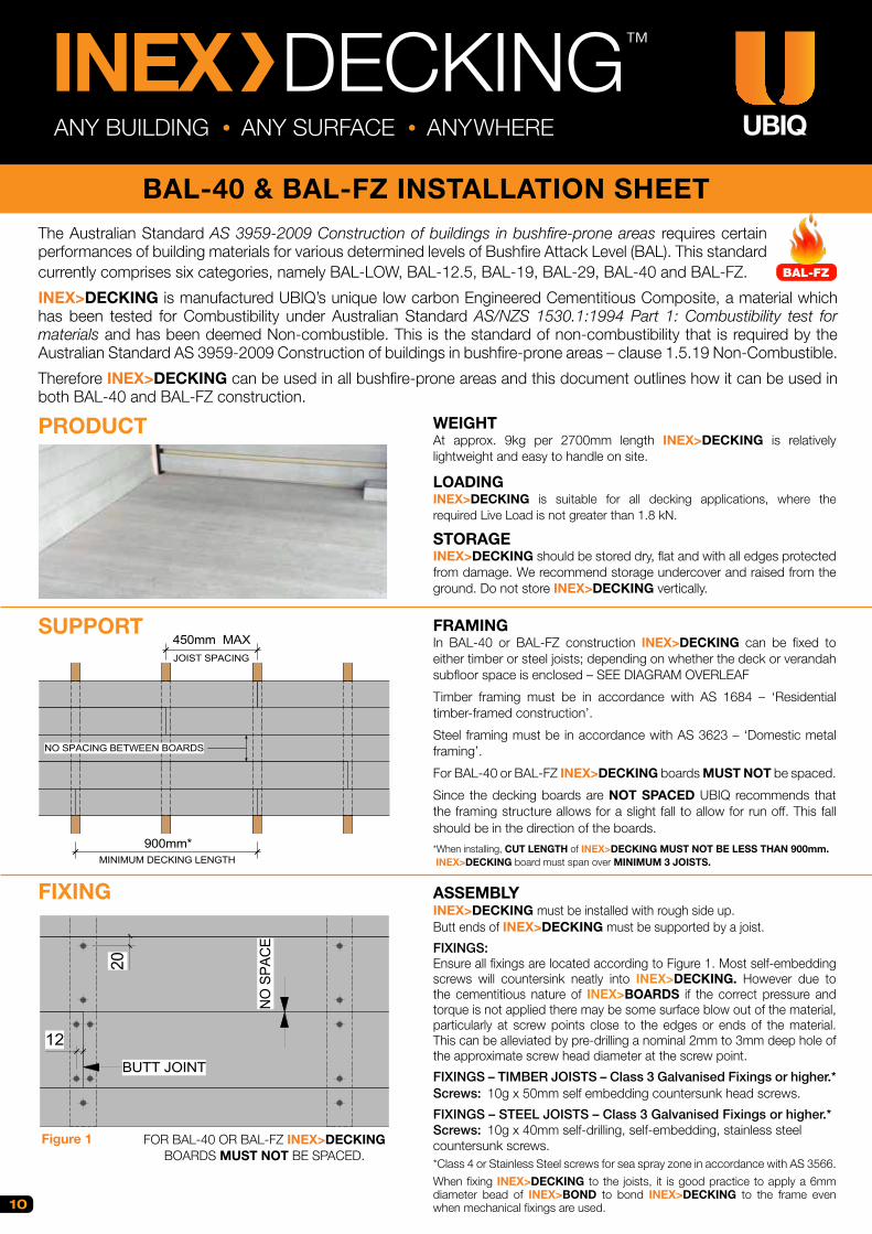
For BAL-40 or BAL-FZ INEX>DECKING boards MUST NOT be spaced.
Since the decking boards are NOT SPACED UBIQ recommends that the framing structure allows for a slight fall to allow for run off. This fall should be in the direction of the boards.
*When installing, CUT LENGTH of INEX>DECKING MUST NOT BE LESS THAN 900mm. INEX>DECKING board must span over MINIMUM 3 JOISTS.
ASSEMBLYINEX>DECKING must be installed with rough side up.Butt ends of INEX>DECKING must be supported by a joist.
FIXINGS:Ensure all fixings are located according to Figure 1. Most self-embedding screws will countersink neatly into INEX>DECKING. However due to the cementitious nature of INEX>BOARDS if the correct pressure and torque is not applied there may be some surface blow out of the material, particularly at screw points close to the edges or ends of the material. This can be alleviated by pre-drilling a nominal 2mm to 3mm deep hole of the approximate screw head diameter at the screw point.
FIXINGS – TIMBER JOISTS – Class 3 Galvanised Fixings or higher.*Screws: 10g x 50mm self embedding countersunk head screws.
FIXINGS – STEEL JOISTS – Class 3 Galvanised Fixings or higher.*Screws: 10g x 40mm self-drilling, self-embedding, stainless steelcountersunk screws.*Class 4 or Stainless Steel screws for sea spray zone in accordance with AS 3566.
When fixing INEX>DECKING to the joists, it is good practice to apply a 6mm diameter bead of INEX>BOND to bond INEX>DECKING to the frame even when mechanical fixings are used.
The Australian Standard AS 3959-2009 Construction of buildings in bushfire-prone areas requires certain performances of building materials for various determined levels of Bushfire Attack Level (BAL). This standard currently comprises six categories, namely BAL-LOW, BAL-12.5, BAL-19, BAL-29, BAL-40 and BAL-FZ.
INEX>DECKING is manufactured UBIQ’s unique low carbon Engineered Cementitious Composite, a material which has been tested for Combustibility under Australian Standard AS/NZS 1530.1:1994 Part 1: Combustibility test for materials and has been deemed Non-combustible. This is the standard of non-combustibility that is required by the Australian Standard AS 3959-2009 Construction of buildings in bushfire-prone areas – clause 1.5.19 Non-Combustible.
Therefore INEX>DECKING can be used in all bushfire-prone areas and this document outlines how it can be used in both BAL-40 and BAL-FZ construction.
PRODUCT
FIXING
NO SPACING BETWEEN BOARDS
900mm*MINIMUM DECKING LENGTH
450mm MAXJOIST SPACING
20
12
BUTT JOINT
NO
SPA
CE
BAL-FZ
SUPPORT
FOR BAL-40 OR BAL-FZ INEX>DECKINGBOARDS MUST NOT BE SPACED.
Figure 1
BAL-40 & BAL-FZ INSTALLATION SHEET
11
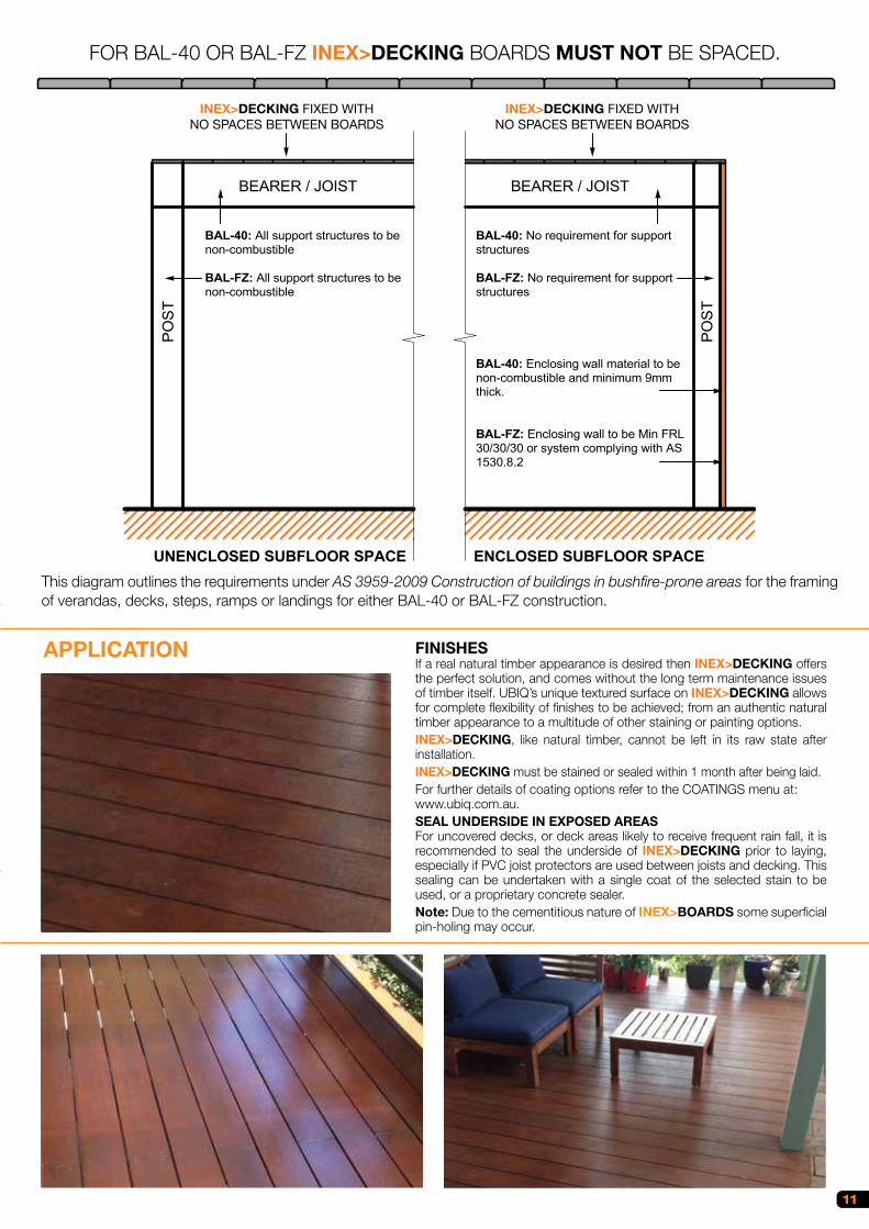
APPLICATION FINISHESIf a real natural timber appearance is desired then INEX>DECKING offers the perfect solution, and comes without the long term maintenance issues of timber itself. UBIQ’s unique textured surface on INEX>DECKING allows for complete flexibility of finishes to be achieved; from an authentic natural timber appearance to a multitude of other staining or painting options.INEX>DECKING, like natural timber, cannot be left in its raw state after installation.INEX>DECKING must be stained or sealed within 1 month after being laid.For further details of coating options refer to the COATINGS menu at:www.ubiq.com.au.SEAL UNDERSIDE IN EXPOSED AREASFor uncovered decks, or deck areas likely to receive frequent rain fall, it is recommended to seal the underside of INEX>DECKING prior to laying, especially if PVC joist protectors are used between joists and decking. This sealing can be undertaken with a single coat of the selected stain to be used, or a proprietary concrete sealer.Note: Due to the cementitious nature of INEX>BOARDS some superficial pin-holing may occur.
UNENCLOSED SUBFLOOR SPACE ENCLOSED SUBFLOOR SPACE
INEX>DECKING FIXED WITHNO SPACES BETWEEN BOARDS
BEARER / JOISTP
OS
T
PO
ST
BAL-40: All support structures to benon-combustible
BAL-FZ: All support structures to be non-combustible
BAL-40: No requirement for support structures
BAL-FZ: No requirement for support structures
BAL-40: Enclosing wall material to be non-combustible and minimum 9mm thick.
BAL-FZ: Enclosing wall to be Min FRL 30/30/30 or system complying with AS 1530.8.2
BEARER / JOIST
INEX>DECKING FIXED WITHNO SPACES BETWEEN BOARDS
This diagram outlines the requirements under AS 3959-2009 Construction of buildings in bushfire-prone areas for the framing of verandas, decks, steps, ramps or landings for either BAL-40 or BAL-FZ construction.
INEX>DECKING FIXED WITHNO SPACES BETWEEN BOARDS
INEX>DECKING FIXED WITHNO SPACES BETWEEN BOARDS
FOR BAL-40 OR BAL-FZ INEX>DECKING BOARDS MUST NOT BE SPACED.

BAL-40 & BAL-FZ INSTALLATION SHEET
ANY BUILDING • ANY SURFACE • ANYWHERE
INEX MAXIDECK™
12
WEIGHTAt approx. 34kg per 2700mm length INEX>MAXIDECK is relatively lightweight and easy to handle on site.
LOADINGINEX>MAXIDECK is suitable for all decking applications, where the required Live Load is not greater than 2.7 kN.
STORAGEINEX>MAXIDECK should be stored dry, flat and with all edges protected from damage. We recommend storage undercover and raised from the ground. Do not store INEX>MAXIDECK vertically.
FRAMINGINEX>MAXIDECK can be fixed to timber or steel joists with spacing at maximum 450mm centres. In BAL-40 or BAL-FZ construction INEX>MAXIDECK can be fixed to either timber or steel joists; depending on whether the deck or verandah subfloor space is enclosed – SEE DIAGRAM OVERLEAF
Timber framing must be in accordance with AS 1684 – ‘Residential timber-framed construction’.
Steel framing must be in accordance with AS 3623 – ‘Domestic metal framing’.
Since the decking boards are NOT SPACED UBIQ recommends that the framing structure allows for a slight fall to allow for run off. This fall should be in the direction of the boards.
ASSEMBLYINEX>MAXIDECK must be installed with rough side up.Butt ends of INEX>MAXIDECK must be supported by a joist.INEX>MAXIDECK can be fitted to a square or staggered layout.
FIXINGS:Ensure all fixings are located according to Figure 1. Most self-embedding screws will countersink neatly into INEX>MAXIDECK. However due to the cementitious nature of INEX>BOARDS if the correct pressure and torque is not applied there may be some surface blow out of the material, particularly at screw points close to the edges or ends of the material. This can be alleviated by pre-drilling a nominal 2mm to 3mm deep hole of the approximate screw head diameter at the screw point.
FIXINGS – TIMBER JOISTS – Class 3 Galvanised Fixings or higher*Screws: 10g x 50mm self embedding countersunk head screws.
FIXINGS – STEEL JOISTS – Class 3 Galvanised Fixings or higher*Screws: 10g x 40mm self-drilling, self-embedding, stainless steelcountersunk screws.*Class 4 or Stainless Steel screws for sea spray zone in accordance with AS 3566.When fixing INEX>MAXIDECK to the joists, it is good practice to apply a 6mm diameter bead of INEX>BOND to bond INEX>MAXIDECK to the frame even when mechanical fixings are used.
The Australian Standard AS 3959-2009 Construction of buildings in bushfire-prone areas requires certain performances of building materials for various determined levels of Bushfire Attack Level (BAL). This standard currently comprises six categories, namely BAL-LOW, BAL-12.5, BAL-19, BAL-29, BAL-40 and BAL-FZ.
INEX>MAXIDECK is manufactured UBIQ’s unique low carbon Engineered Cementitious Composite, a material which has been tested for Combustibility under Australian Standard AS/NZS 1530.1:1994 Part 1: Combustibility test for materials and has been deemed Non-combustible. This is the standard of non-combustibility that is required by the Australian Standard AS 3959-2009 Construction of buildings in bushfire-prone areas – clause 1.5.19 Non-Combustible.
As there is no spacing between individual decking boards, INEX>MAXIDECK therefore can be used in all bushfire-prone areas and this document outlines how it can be used in both BAL-40 and BAL-FZ construction.
BAL-FZ & BELOW COMPLIANCE
PRODUCT
SUPPORT
450mmMAX
600m
m
2700mm
BUTT JOINT
BAL-FZ
FIXING
12
BUTT JOINT
TONGUE
EQ
EQEQ
EQ
TRIMMER JOIST**GROOVE
Figure 1
**All frame edges must have trimmer joists as support.

BAL-40 & BAL-FZ INSTALLATION SHEET
13
APPLICATION
UNENCLOSED SUBFLOOR SPACE ENCLOSED SUBFLOOR SPACE
INEX>DECKING FIXED WITHNO SPACES BETWEEN BOARDS
BEARER / JOIST
PO
ST
PO
ST
BAL-40: All support structures to benon-combustible
BAL-FZ: All support structures to be non-combustible
BAL-40: No requirement for support structures
BAL-FZ: No requirement for support structures
BAL-40: Enclosing wall material to be non-combustible and minimum 9mm thick.
BAL-FZ: Enclosing wall to be Min FRL 30/30/30 or system complying with AS 1530.8.2
BEARER / JOIST
INEX>DECKING FIXED WITHNO SPACES BETWEEN BOARDS
UNENCLOSED SUBFLOOR SPACE ENCLOSED SUBFLOOR SPACE
INEX>MAXIDECK
BEARER / JOISTP
OS
T
PO
ST
BAL-40: All support structures to benon-combustible
BAL-FZ: All support structures to be non-combustible
BAL-40: No requirement for support structures
BAL-FZ: No requirement for support structures
BAL-40: Enclosing wall material to be non-combustible and minimum 9mm thick.
BAL-FZ: Enclosing wall to be Min FRL 30/30/30 or system complying with AS 1530.8.2
BEARER / JOIST
INEX>MAXIDECK
This diagram outlines the requirements under AS 3959-2009 Construction of buildings in bushfire-prone areas for the framing of verandas, decks, steps, ramps or landings for either BAL-40 or BAL-FZ construction.
INEX>MAXIDECK INEX>MAXIDECK
INEX>MAXIDECK BY DEFAULT IS BAL-40 & BAL-FZ COMPLIANT.
FINISHESIf a real natural timber appearance is desired then INEX> MAXIDECK offers the perfect solution, and comes without the long term maintenance issues of timber itself. UBIQ’s unique textured surface on INEX>MAXIDECK allows for complete flexibility of finishes to be achieved; from an authentic natural timber appearance to a multitude of other staining or painting options.INEX>MAXIDECK, like natural timber, cannot be left in its raw state after installation.INEX>MAXIDECK must be stained or sealed within 1 month after being laid.For further details of coating options refer to the COATINGS menu at:www.ubiq.com.au.SEAL UNDERSIDE IN EXPOSED AREASFor uncovered decks, or deck areas likely to receive frequent rain fall, it is recommended to seal the underside of INEX>DECKING prior to laying, especially if PVC joist protectors are used between joists and decking. This sealing can be undertaken with a single coat of the selected stain to be used, or a proprietary concrete sealer.Note: Due to the cementitious nature of INEX>BOARDS some superficial pin-holing may occur.
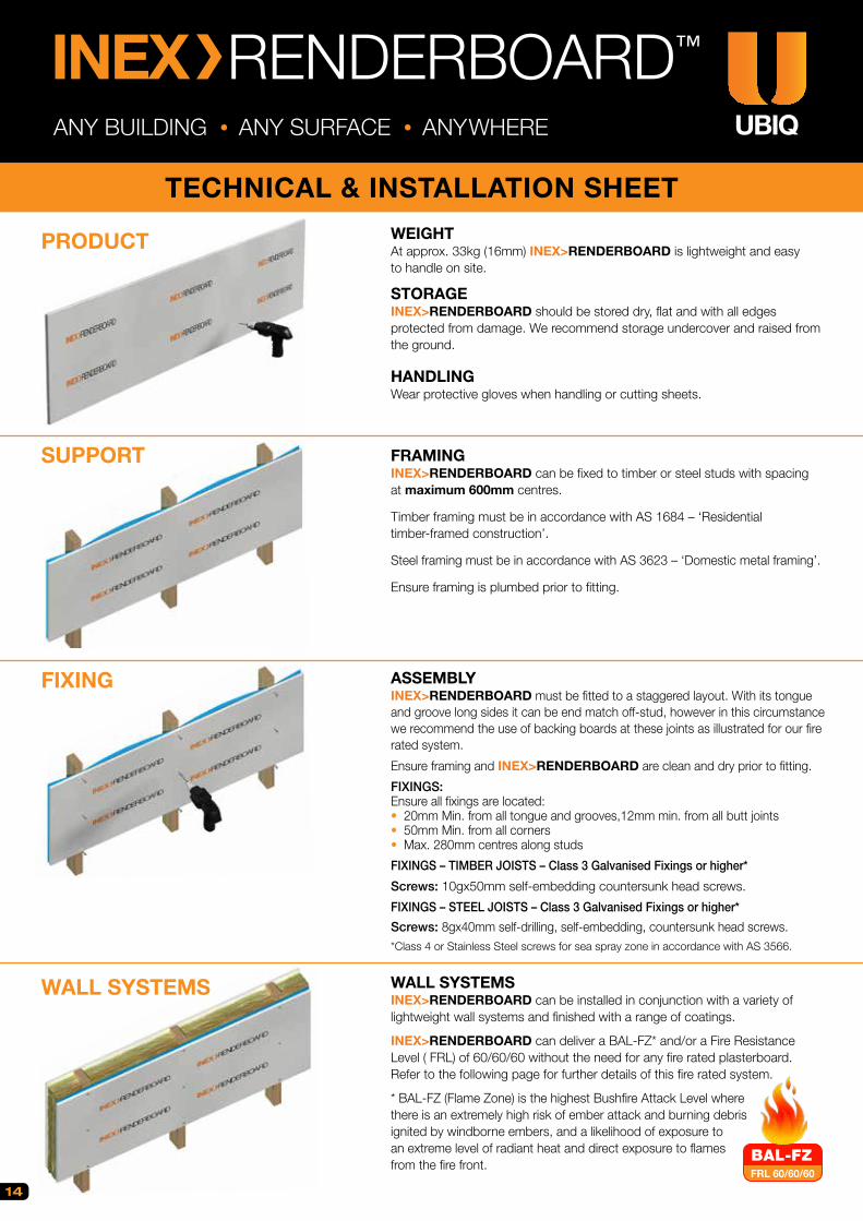
WEIGHTAt approx. 33kg (16mm) INEX>RENDERBOARD is lightweight and easy to handle on site.
STORAGEINEX>RENDERBOARD should be stored dry, flat and with all edges protected from damage. We recommend storage undercover and raised from the ground.
HANDLINGWear protective gloves when handling or cutting sheets.
FRAMINGINEX>RENDERBOARD can be fixed to timber or steel studs with spacing at maximum 600mm centres.
Timber framing must be in accordance with AS 1684 – ‘Residential timber-framed construction’.
Steel framing must be in accordance with AS 3623 – ‘Domestic metal framing’.
Ensure framing is plumbed prior to fitting.
ASSEMBLYINEX>RENDERBOARD must be fitted to a staggered layout. With its tongue and groove long sides it can be end match off-stud, however in this circumstance we recommend the use of backing boards at these joints as illustrated for our fire rated system.
Ensure framing and INEX>RENDERBOARD are clean and dry prior to fitting.
FIXINGS:Ensure all fixings are located:• 20mm Min. from all tongue and grooves,12mm min. from all butt joints• 50mm Min. from all corners• Max. 280mm centres along studs
FIXINGS – TIMBER JOISTS – Class 3 Galvanised Fixings or higher*
Screws: 10gx50mm self-embedding countersunk head screws.
FIXINGS – STEEL JOISTS – Class 3 Galvanised Fixings or higher*
Screws: 8gx40mm self-drilling, self-embedding, countersunk head screws.*Class 4 or Stainless Steel screws for sea spray zone in accordance with AS 3566.
WALL SYSTEMSINEX>RENDERBOARD can be installed in conjunction with a variety oflightweight wall systems and finished with a range of coatings.
INEX>RENDERBOARD can deliver a BAL-FZ* and/or a Fire Resistance Level ( FRL) of 60/60/60 without the need for any fire rated plasterboard.Refer to the following page for further details of this fire rated system.
* BAL-FZ (Flame Zone) is the highest Bushfire Attack Level where there is an extremely high risk of ember attack and burning debris ignited by windborne embers, and a likelihood of exposure to an extreme level of radiant heat and direct exposure to flames from the fire front.
PRODUCT
WALL SYSTEMS
TECHNICAL & INSTALLATION SHEET
INEX RENDERBOARD™
ANY BUILDING • ANY SURFACE • ANYWHERE
SUPPORT
FIXING
FRL 60/60/60
BAL-FZ
14
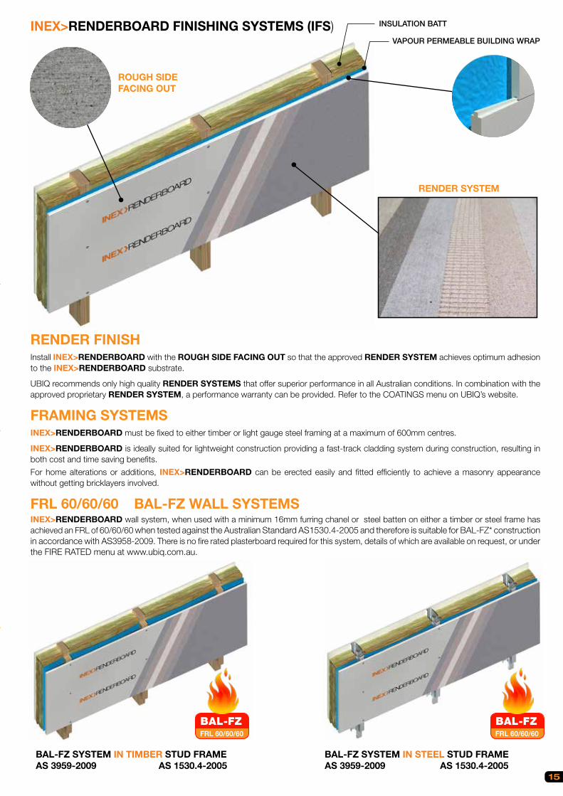
TECHNICAL & INSTALLATION SHEET
15
INEX>RENDERBOARD FINISHING SYSTEMS (IFS)
ROUGH SIDE FACING OUT
RENDER SYSTEM
BAL-FZ SYSTEM IN TIMBER STUD FRAME AS 3959-2009 AS 1530.4-2005
BAL-FZ SYSTEM IN STEEL STUD FRAME AS 3959-2009 AS 1530.4-2005
RENDER FINISHInstall INEX>RENDERBOARD with the ROUGH SIDE FACING OUT so that the approved RENDER SYSTEM achieves optimum adhesion to the INEX>RENDERBOARD substrate.
UBIQ recommends only high quality RENDER SYSTEMS that offer superior performance in all Australian conditions. In combination with the approved proprietary RENDER SYSTEM, a performance warranty can be provided. Refer to the COATINGS menu on UBIQ’s website.
FRAMING SYSTEMSINEX>RENDERBOARD must be fixed to either timber or light gauge steel framing at a maximum of 600mm centres.
INEX>RENDERBOARD is ideally suited for lightweight construction providing a fast-track cladding system during construction, resulting in both cost and time saving benefits.
For home alterations or additions, INEX>RENDERBOARD can be erected easily and fitted efficiently to achieve a masonry appearance without getting bricklayers involved.
FRL 60/60/60 BAL-FZ WALL SYSTEMS INEX>RENDERBOARD wall system, when used with a minimum 16mm furring chanel or steel batten on either a timber or steel frame has achieved an FRL of 60/60/60 when tested against the Australian Standard AS1530.4-2005 and therefore is suitable for BAL-FZ* construction in accordance with AS3958-2009. There is no fire rated plasterboard required for this system, details of which are available on request, or under the FIRE RATED menu at www.ubiq.com.au.
FRL 60/60/60
BAL-FZFRL 60/60/60
BAL-FZ
INSULATION BATT
VAPOUR PERMEABLE BUILDING WRAP

INEX>RENDERBOARD must be fitted in a staggered pattern to achieve the best surface and finish. Vertical butt joint locations are subject to stud spacing. Refer to Figure 1.
For render application, INEX>RENDERBOARD must be fitted with rough side facing out for best adhesion.
STARTER & CORNER TRIMSWhen applying render to INEX>RENDERBOARD, starter trims and corner trims must be fixed in accordance with trim or render manufacturer’s instructions. To achieve best adhesion between trim and render, ensure that the render fully covers both INEX>RENDERBOARD and the trim, thus resulting in a perfectly flat and seamless rendered surface.
MOVEMENT CONTROL JOINTDespite the fact that INEX>RENDERBOARD is dimensionally stable, movement control joints must be installed to relieve any stress on building materials due to temperature changes, sway caused by wind, seismic events and etc.
Vertical movement control joints are to be provided where wall lengths exceed 8m, at changes of wall direction and at openings such as windows and doorways or where existing structural joints are located. Refer to Figure 2.
Horizontal movement control joints must also be provided at each floor level, subject to designer’s detailing.
Control joints should be installed evenly and symmetrically for large size walls.
LAYING PATTERN
Figure 1
Figure 2
STARTER TRIM ➊42-RST16-3.5
CORNER TRIM ➋42-RMESH-3.5
➋➊
INEX>RENDERBOARD
FOAM BACKER ROD / AIR SEAL
VEE JOINT
Figure 2
INEX>RENDERBOARD
INEX>BOND OR PAINTABLEPOLYURETHANE FLEXIBLESEALANT
RENDER SYSTEM
ONE EXAMPLE OF MOVEMENT CONTROL JOINT
16
17
INSTALLATION EQUIPMENTUBIQ recommends the following equipment and accessories for the installation of INEX>RENDERBOARD:
GENERAL: INEX>RENDERBOARD can be machined and worked in same way as comparable fibre cement wall sheeting.
CUTTING: INEX>RENDERBOARD should be cut using a mechanical dust reducing circular saw with a diamond edge blade, similar to that used to cut softer brick or stone or the ones specifically used to cut fibre cement sheet. See also Health & Safety section below.
SCREW FIXING: INEX>RENDERBOARD must be screw fixed only. Use a cordless power drill.
DUST LIMITATION: Always limit dust with a vacuum dust extraction system with a suitable filter.
CONTROL JOINT: When installing INEX>RENDERBOARD in situation where wall height is more than one storey, horizontal movement control joints are required at each level. Standard V-joints, starter trims or shadowline trims can be used, subject to designer’s detailing. Movement control joints are to be provided where wall dimensions exceed 8m in the long sheet direction, at changes of wall direction and at openings such as windows and doorways or where existing structural joints are located.
BACKING ROD: Where movement control joints are needed in any INEX>RENDERBOARD application, use a closed cell PE foam backing rod of 10–12mm diameter to control the design depth of INEX>BOND adhesive/sealant used to seal the joint. For more details refer to the INEX>BOND product data sheet.Important Notes:Ensure all components are compatible with each other and suitable for INEX>RENDERBOARD and/or the intended surface finish.Failure to install, finish or maintain this product in accordance with relevant building codes, regulations, standards and UBIQ’s current published instructions may lead to personal injury, affect system performance, violate local building codes, and possibly void the product warranty.
MATERIAL PROPERTIESINEX>RENDERBOARD is an advanced high strength, low carbon fibre reinforced Engineered Cementitious Composite (ECC) product, containing 60% of post industrial recycled materials.
INEX>RENDERBOARD conforms to the requirements of AS/NZS 2908.2 2000 ‘Cellulose-cement products Part 2: Flat sheets’, other than the optional ‘Warm Water’ test item 6.4. In this test, INEX>RENDERBOARD performs to a mean MPa of >10.
INEX>RENDERBOARD conforms to AS 4964 2004 as containing no asbestos. It is toxin free and is 100% recyclable.
INEX>RENDERBOARD itself is deemed non-combustible when tested in accordance with AS/NZS 1530.1 and is therefore a non-combustible material suitable for Bushfire BAL-40 under AS3959-2009.
INEX>RENDERBOARD when tested in accordance with the Australian Standards displayed the following fire hazard indices: AS/NZS 1530.2 - Flammability: 0 and AS/NZS 1530.3 - Ignitability: 0; Spread of Flame: 0; Heat Evolved: 0 and Smoke Developed: 1.
INEX>RENDERBOARD when tested in accordance with AS/NZS 3837-1998 for heat and smoke release rates is classified Group 1 for Specification A2.4 of the BCA.
INEX>RENDERBOARD wall system conforms to the requirements of AS 3959-2009 when tested against all bush fire zones and bush fire attack levels. INEX>RENDERBOARD wall system has achieved a fire resistance level (FRL) of 60/60/60 in accordance with AS 1530.4-2005 and therefore is suitable for BAL-FZ construction*.
INEX>RENDERBOARD is not susceptible to Termite Attack.
*Details of BAL-FZ and FRL 60/60/60 wall systems are available on request, or under the FIRE RATED menu at www.ubiq.com.au.
HEALTH & SAFETYUBIQ advises that INEX>RENDERBOARD contains fiberglass reinforcing and causes fine dust when cutting or machining. Continuous or excessive inhalation of fine dust containing fiberglass particles can cause irritation and may cause lung scarring (silicosis). This dust could be carcinogenic as all dust may be. Exposure to such dust may cause irritation to the skin or other body surfaces.
When cutting INEX>RENDERBOARD use methods recommended in this brochure to minimise dust production, and in addition:
LOCATION: Do not cut INEX>RENDERBOARD indoors. Cut in a well ventilated outdoor location.
CLOTHING, MASK & GOGGLES: Always wear protective clothing and properly fitted and approved mask (respirator) and eye protective goggles.
DUST LIMITATION: Always use a mechanical circular saw equipped with a fitted dust extraction system. When cutting is finished always vacuum up residual dust. Maintain the work area as a dust free environment.
Note: Due to the cementitious nature of INEX>BOARDS some superficial pin-holing may occur.
The smooth side of INEX>RENDERBOARD is characterised as a Class 2 concrete finish.
FRL 60/60/60
BAL-FZ

WEIGHTAt approx. 12kg per length (16mm) INEX>WEATHERBOARD is lightweight and easy to handle on site.
STORAGEINEX>WEATHERBOARD should be stored dry, flat and with all edges protected from damage. We recommend storage undercover and raised from the ground.
HANDLINGWear protective gloves when handling or cutting INEX>WEATHERBOARD.
FRAMINGINEX>WEATHERBOARD can be fixed to timber or steel studs with spacing at maximum 600mm centres.
Timber framing must be in accordance with AS 1684 – ‘Residential timber-framed construction’.
Steel framing must be in accordance with AS 3623 – ‘Domestic metal framing’.
Ensure framing is plumbed prior to fitting.
ASSEMBLYWe recommend INEX>WEATHERBOARD be fitted to a staggered layout. With its tongue and groove ends it can be off-stud end jointed.
Ensure framing and INEX>WEATHERBOARD are clean and dry prior to fitting.
FIXINGS:Ensure all fixings are located:• 20mm Min. from top edge of weatherboard ( no pre-drilling required ) • 12mm Min. from tongue and groove joint when centering joint to stud to avoid any damage to the tongue and groove edges.
FIXINGS – TIMBER JOISTS – Class 3 Galvanised Fixings or higher*
Screws: 10gx50mm self-embedding countersunk head screws.
FIXINGS – STEEL JOISTS – Class 3 Galvanised Fixings or higher*
Screws: 8gx40mm self-drilling, self-embedding, countersunk head screws.*Class 4 or Stainless Steel screws for sea spray zone in accordance with AS 3566
WALL SYSTEMSINEX>WEATHERBOARD can be installed in conjunction with a variety oflightweight wall systems and finished with a range of paint finishes or coatings.
INEX>WEATHERBOARD can deliver a BAL-FZ* and/or a Fire Resistance Level ( FRL) of 60/60/60 without the need for any fire rated plasterboard or fire rated sealants. Refer to the following page for further details of thisfire rated system.
* BAL-FZ (Flame Zone) is the highest Bushfire Attack Level where there is an extremely high risk of ember attack and burning debris ignited by windborne embers, and a likelihood of exposure to an extreme level of radiant heat and direct exposure to flames from the fire front.
PRODUCT
WALL SYSTEMS
TECHNICAL & INSTALLATION SHEET
INEX WEATHERBOARD™
ANY BUILDING • ANY SURFACE • ANYWHERE
SUPPORT
FIXING
FRL 60/60/60
BAL-FZ
18
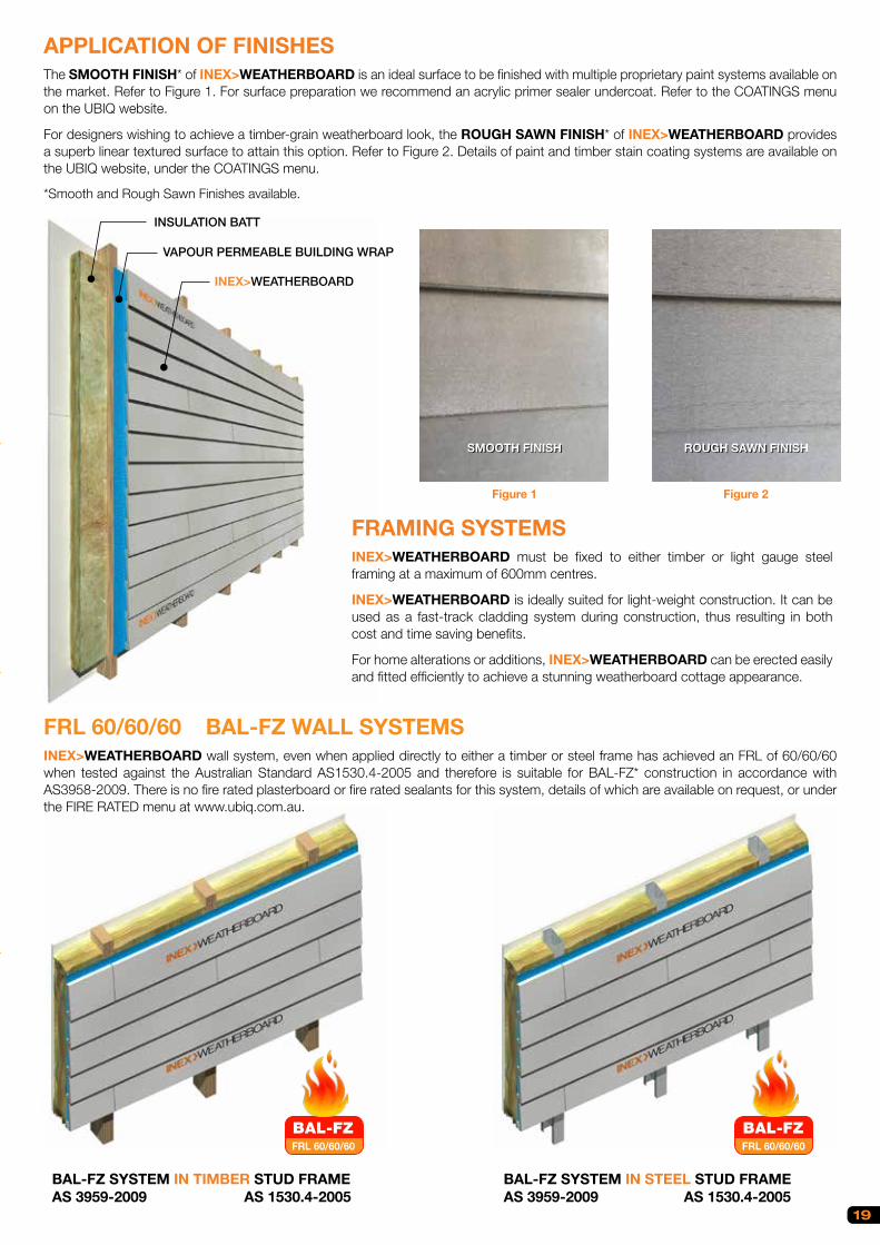
19
TECHNICAL & INSTALLATION SHEET
APPLICATION OF FINISHESThe SMOOTH FINISH* of INEX>WEATHERBOARD is an ideal surface to be finished with multiple proprietary paint systems available on the market. Refer to Figure 1. For surface preparation we recommend an acrylic primer sealer undercoat. Refer to the COATINGS menu on the UBIQ website.
For designers wishing to achieve a timber-grain weatherboard look, the ROUGH SAWN FINISH* of INEX>WEATHERBOARD provides a superb linear textured surface to attain this option. Refer to Figure 2. Details of paint and timber stain coating systems are available on the UBIQ website, under the COATINGS menu.
*Smooth and Rough Sawn Finishes available.
FRL 60/60/60 BAL-FZ WALL SYSTEMS INEX>WEATHERBOARD wall system, even when applied directly to either a timber or steel frame has achieved an FRL of 60/60/60 when tested against the Australian Standard AS1530.4-2005 and therefore is suitable for BAL-FZ* construction in accordance with AS3958-2009. There is no fire rated plasterboard or fire rated sealants for this system, details of which are available on request, or under the FIRE RATED menu at www.ubiq.com.au.
BAL-FZ SYSTEM IN TIMBER STUD FRAME AS 3959-2009 AS 1530.4-2005
BAL-FZ SYSTEM IN STEEL STUD FRAME AS 3959-2009 AS 1530.4-2005
FRAMING SYSTEMSINEX>WEATHERBOARD must be fixed to either timber or light gauge steel framing at a maximum of 600mm centres.
INEX>WEATHERBOARD is ideally suited for light-weight construction. It can be used as a fast-track cladding system during construction, thus resulting in both cost and time saving benefits.
For home alterations or additions, INEX>WEATHERBOARD can be erected easily and fitted efficiently to achieve a stunning weatherboard cottage appearance.
Figure 1
SMOOTH FINISH ROUGH SAWN FINISH
Figure 2
FRL 60/60/60
BAL-FZFRL 60/60/60
BAL-FZ
INSULATION BATT
VAPOUR PERMEABLE BUILDING WRAP
INEX>WEATHERBOARD

GROOVE TONGUE
172 20
4
150 18
0
WID
TH
CO
VE
RA
GE
CO
VE
RA
GE
WID
TH
GR
OO
VE
TON
GU
E
DOUBLE STUDS
DESIGN PINE EXTERNAL CORNER MOULD
VAPOUR PERMEABLE BUILDING WRAP CONTINOUS AROUND CORNER
INEX>WEATHERBOARD
DESIGN PINE
2mm BEAD OF INEX>BONDSEALANT
TIMBER STUD
INEX>WEATHERBOARD
2mm BEAD OFINEX>BOND SEALANT
INEX>STARTERTRIM3000 x 30 x 16mm
20
20
INEX>BOND
(DETAIL 1)
APPROVED FLASHINGTO REQUIREMENTS
APPROVED FLASHINGTO REQUIREMENTS
VAPOUR PERMEABLEBUILDING WRAP
VAPOUR PERMEABLEBUILDING WRAP CONTINOUS AROUND CORNER
INEX>WEATHERBOARD must be fitted in a staggered patternto achieve the best surface and finish. Refer to Figure 3.
When installing INEX>WEATHERBOARD, corner trims must befixed in accordance with trim manufacturer's instructions.
CORNER TRIMS
2 types of coverage are available for INEX>WEATHERBOARD:For 180mm wide board, coverage = 150mmFor 204mm wide board, coverage = 172mm
BOARD COVERAGE
INEX>STARTERTRIM (Product Code: IST30316) must be used wheninstalling the first row of INEX>WEATHERBOARD. See Detail 1 of Figure 8.
STARTER TRIMS
TONGUE AND GROOVE JOINTApply a 2mm to 3mm diameter bead of INEX>BOND to the tongueand groove joints along the short ends of INEX>WEATHERBOARD.Refer to Figures 6 & 7.
INTERNAL CORNER TRIM DETAIL
EXTERNAL CORNER TRIM DETAIL
Figure 4
Figure 5
Figure 6
Figure 7
Figure 8
Figure 3
SIMILAR DETAIL FOR BUSH FIRE ZONES AVAILABLE ON REQUEST
SIMILAR DETAIL FOR BUSH FIRE ZONES AVAILABLE ON REQUEST
LAYING PATTERN
20
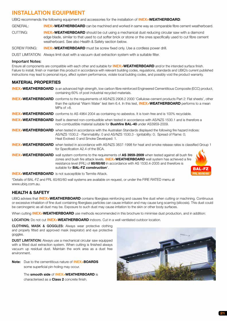
21
INSTALLATION EQUIPMENTUBIQ recommends the following equipment and accessories for the installation of INEX>WEATHERBOARD:
GENERAL: INEX>WEATHERBOARD can be machined and worked in same way as comparable fibre cement weatherboard.
CUTTING: INEX>WEATHERBOARD should be cut using a mechanical dust reducing circular saw with a diamond edge blade, similar to that used to cut softer brick or stone or the ones specifically used to cut fibre cement weatherboard. See also Health & Safety section below.
SCREW FIXING: INEX>WEATHERBOARD must be screw fixed only. Use a cordless power drill.
DUST LIMITATION: Always limit dust with a vacuum dust extraction system with a suitable filter.
Important Notes:Ensure all components are compatible with each other and suitable for INEX>WEATHERBOARD and/or the intended surface finish.Failure to install, finish or maintain this product in accordance with relevant building codes, regulations, standards and UBIQ’s current published instructions may lead to personal injury, affect system performance, violate local building codes, and possibly void the product warranty.
MATERIAL PROPERTIESINEX>WEATHERBOARD is an advanced high strength, low carbon fibre reinforced Engineered Cementitious Composite (ECC) product, containing 60% of post industrial recycled materials.
INEX>WEATHERBOARD conforms to the requirements of AS/NZS 2908.2 2000 ‘Cellulose-cement products Part 2: Flat sheets’, other than the optional ‘Warm Water’ test item 6.4. In this test, INEX>WEATHERBOARD performs to a mean MPa of >8.
INEX>WEATHERBOARD conforms to AS 4964 2004 as containing no asbestos. It is toxin free and is 100% recyclable.
INEX>WEATHERBOARD itself is deemed non-combustible when tested in accordance with AS/NZS 1530.1 and is therefore a non-combustible material suitable for Bushfire BAL-40 under AS3959-2009.
INEX>WEATHERBOARD when tested in accordance with the Australian Standards displayed the following fire hazard indices: AS/NZS 1530.2 - Flammability: 0 and AS/NZS 1530.3 - Ignitability: 0; Spread of Flame: 0; Heat Evolved: 0 and Smoke Developed: 1.
INEX>WEATHERBOARD when tested in accordance with AS/NZS 3837-1998 for heat and smoke release rates is classified Group 1 for Specification A2.4 of the BCA.
INEX>WEATHERBOARD wall system conforms to the requirements of AS 3959-2009 when tested against all bush fire zones and bush fire attack levels. INEX>WEATHERBOARD wall system has achieved a fire resistance level (FRL) of 60/60/60 in accordance with AS 1530.4-2005 and therefore is suitable for BAL-FZ construction*.
INEX>WEATHERBOARD is not susceptible to Termite Attack.
*Details of BAL-FZ and FRL 60/60/60 wall systems are available on request, or under the FIRE RATED menu at www.ubiq.com.au.
HEALTH & SAFETYUBIQ advises that INEX>WEATHERBOARD contains fiberglass reinforcing and causes fine dust when cutting or machining. Continuous or excessive inhalation of fine dust containing fiberglass particles can cause irritation and may cause lung scarring (silicosis). This dust could be carcinogenic as all dust may be. Exposure to such dust may cause irritation to the skin or other body surfaces.
When cutting INEX>WEATHERBOARD use methods recommended in this brochure to minimise dust production, and in addition:
LOCATION: Do not cut INEX>WEATHERBOARD indoors. Cut in a well ventilated outdoor location.
CLOTHING, MASK & GOGGLES: Always wear protective clothing and properly fitted and approved mask (respirator) and eye protective goggles.
DUST LIMITATION: Always use a mechanical circular saw equipped with a fitted dust extraction system. When cutting is finished always vacuum up residual dust. Maintain the work area as a dust free environment.
Note: Due to the cementitious nature of INEX>BOARDS some superficial pin-holing may occur.
The smooth side of INEX>WEATHERBOARD is characterised as a Class 2 concrete finish.
FRL 60/60/60
BAL-FZ

Fastening Solutions
When performance is critical
Sometimes you need a fastener that does more. Maybe you’re
looking for higher loads or additional corrosion resistance, or
perhaps an installation method that saves time on a repetitive
application. Whatever it is, you are no longer looking for just
a fastener, what you are really looking for is a solution.
When faced with such challenges look to Simpson Strong-Tie.
We specialise in these performance-critical challenges,
offering fasteners and installation systems that uniquely suit
the applications for which they are intended. By blending field
research with insightful design and the highest-quality materials,
we are able to offer premium fastening products with the features
that ensure a successful result for almost any application.
Application Fastening to Screw
INEX>FLOOR
INEX>DECKING
Softwood & Hardwood JoistSSDHSD50S
10g x 50mm 305 stainless steel
Steel Joists (1.2-3.0mm thick)
SSBFHSD2SA
10g x 50mm 316 stainless steel
CBSDGL158SA
10g x 42mm class 3 mech. galv.
INEX>WEATHERBOARD
INEX>RENDERBOARD
Softwood & Hardwood FrameSSDHSD50S
10g x 50mm 305 stainless steel
Steel Frame (1.2-3.0mm thick)
SSBFHSD2SA
10g x 50mm 316 stainless steel
Steel Frame (0.8-2.4mm thick)
CBSDG158SA
8g x 42mm class 3 mech. galv.
22

Fastening Solutions
When performance is critical
Sometimes you need a fastener that does more. Maybe you’re
looking for higher loads or additional corrosion resistance, or
perhaps an installation method that saves time on a repetitive
application. Whatever it is, you are no longer looking for just
a fastener, what you are really looking for is a solution.
When faced with such challenges look to Simpson Strong-Tie.
We specialise in these performance-critical challenges,
offering fasteners and installation systems that uniquely suit
the applications for which they are intended. By blending field
research with insightful design and the highest-quality materials,
we are able to offer premium fastening products with the features
that ensure a successful result for almost any application.
Application Fastening to Screw
INEX>FLOOR
INEX>DECKING
Softwood & Hardwood JoistSSDHSD50S
10g x 50mm 305 stainless steel
Steel Joists (1.2-3.0mm thick)
SSBFHSD2SA
10g x 50mm 316 stainless steel
CBSDGL158SA
10g x 42mm class 3 mech. galv.
INEX>WEATHERBOARD
INEX>RENDERBOARD
Softwood & Hardwood FrameSSDHSD50S
10g x 50mm 305 stainless steel
Steel Frame (1.2-3.0mm thick)
SSBFHSD2SA
10g x 50mm 316 stainless steel
Steel Frame (0.8-2.4mm thick)
CBSDG158SA
8g x 42mm class 3 mech. galv.
23

INEX BOND™
PRODUCT ATTRIBUTES
INEX>BOND – MS Polymer elastic adhesive/sealant with a broad adhesion spectrum and high durability
Product Description INEX>BOND is a high-quality, exterior-grade, multi-purpose, non-sag, paintable, one-part adhesive/sealant that cures on exposure to atmospheric moisture to form a durable elastomer. For use to seal joints that must accommodate movement,* in any structure, etc., in conjunction with recommended mechanical fixings (nails and screws). INEX>BOND will bond to many materials including most timbers, metals, metal primers and paint coatings (one and two-part systems), ceramics and many plastics. INEX>BOND can provide an elastic water, gas and dust proof seal to ‘moving’ joints in many structures.
Typical Applications • The primary application is to seal the joints between INEX>FLOOR boards when used in wet areas such as bathrooms, toilets, laundries, kitchens, balconies and decks.• To seal control joints in ceramic tiled floors in ‘L’ shaped rooms, etc.• In light foot traffic areas it can be used to bond INEX>FLOOR boards to timber or metal joists.• Sealing joints in building facades, around door and window frames and other expansion joints.
Product Benefits• Adheres to many surfaces without primers*• Bonds well to old well-cleaned INEX>BOND adhesive/sealant• Permanently elastic• Odour free• Solvent free• Non-corrosive• Non-sagging in a 40mm wide joint• Superior weatherability to polyurethane sealants and adhesives• Resistant to: water, dilute inorganic acids and alkalis, aliphatic solvents, oils and greases*• Many paint systems can be applied within 10 minutes to 4 hours of application or sooner in some cases.*
Available in 290ml Cartridges and 600ml Sausages
* Pre-testing advised.
24
MARKET SECTORS

INEX BOARDS™
25
MARKET SECTORS
Royal Randwick Racecourse Upgrade NSWEntire area of adaptive reuse of existing stadium. Tiered platforms for new executive boxes and bar areas2,000m2
Wesley College Expansion, University of Sydney NSW2 layers of INEX>FLOOR over entire area of 44 new student accommodation rooms1,500m2
St Mary’s Catholic Church, Concord NSWINEX>FLOOR for entire new floor to church nave, aisles and chapels1,500m2
Bungan Beach House NSWINEX>FLOORINEX>WALLBOARD1,000m2
The Captain’s House, Byron Bay NSWINEX>WEATHERBOARD External INEX>WALLBOARD all internal walls and ceilings. 1,000m2
Byron Bay Tree Top Holiday House NSWINEX>FLOOR with timber stain for Bushfire Zones where timber is not possible. All surfaces, internal / external850m2
Traffic corridor noise abatement fencingRoadside noise abatement fence panelMultiple Kilometers
ILVE Appliances Showroom, 48 Moore St, LeichhardtINEX>FLOOR provided an affordable alternative to a polished concrete-style finish150m2
CLIENT PROJECT CONTRACTOR
RECREATIONAL
PUBLIC INFRASTRUCTURE / (RAIL TRANSPORT)
INSTITUTIONAL EDUCATION
ECCLESIASTICAL
COMMERCIAL
RESIDENTIAL
PUBLIC INFRASTRUCTURE / (ACOUSTIC FENCING – ROAD & RAIL)
Archdioceseof Sydney
PRIVATEHOME OWNER
PRIVATEHOME OWNER
CRUXBUILDING
CRUXBUILDING
Bungan Beach House NSWINEX>FLOOR was chosen for this 7.5m cantilevered balcony. A lightweight but high strength floor substrate to provide cross bracing and stiffness which was achieved with INEX>FLOOR 16mm. This balcony also achieved BAL-FZ.

NOTES
BAL-FZ
INEX BOARDS™
BUILD A FIRE-RATED HOME* WITH
BAL-FZ – 60/60/60 – NO FIRE RATED PLASTERBOARD REQUIRED
INEX WEATHERBOARDTM
BAL-FZ – 60/60/60 - NO FIRE RATED PLASTERBOARD REQUIRED
INEX RENDERBOARDTM
BAL-FZINEX FLOORTM
BAL-FZINEX DECKINGTM
BAL-FZINEX MAXIDECKTM
*Refer to UBIQ websitefor further information
NOTES
Thank you for considering INEX>BOARDSTM
INEX BOARDS™
BUILD A FIRE-RATED HOME* WITH

The mark of responsible forestry
SGS-000-000000 Revised May 2015
57 St. Hilliers Road, Auburn, NSW 2144
Phone: 1300 00 UBIQ • +612 9519 4460
www.ubiq.com.au