Embed Size (px)
Citation preview

Confidently. Accurately.
Inertial+Inertial
and GNSSmeasurement
system
User Manual
2 Oxford Technical Solutions
Legal Notice
Information furnished is believed to be accurate and reliable. However, Oxford Technical Solutions Limited assumes no responsibility for the consequences of use of such information nor for any infringement of patents or other rights of third parties which may result from its use. No license is granted by implication or otherwise under any patent or patent rights of Oxford Technical Solutions Limited. Specifications mentioned in this publication are subject to change without notice and do not represent a commitment on the part of Oxford Technical Solutions Limited. This publication supersedes and replaces all information previously supplied. Oxford Technical Solutions Limited products are not authorised for use as critical components in life support devices or systems without express written approval of Oxford Technical Solutions Limited.
All brand names are trademarks of their respective holders.
The software is provided by the contributors “as is” and any express or implied warranties, including, but not limited to, the implied warranties of merchantability and fitness for a particular purpose are disclaimed. In no event shall the contributors be liable for any direct, indirect, incidental, special, exemplary, or consequential damages (including, but not limited to, procurement of substitute goods or services; loss of use, data, or profits; or business interruption) however caused and on any theory of liability, whether in contract, strict liability, or tort (including negligence or otherwise) arising in any way out of the use of this software, even if advised of the possibility of such damage.
Copyright Notice
© Copyright 2015, Oxford Technical Solutions.
Revision
Document Revision: 150714 (See Revision History for detailed information).
Contact Details
Oxford Technical Solutions Limited 77 Heyford Park Upper Heyford Oxfordshire OX25 5HD United Kingdom
Tel: +44 (0) 1869 238 015 Fax: +44 (0) 1869 238 016 Web: http://www.oxts.com Email: [email protected]
Inertial+ User Manual
Revision: 150714 3
Warranty
Oxford Technical Solutions Limited (OxTS) warrants the Inertial+ products to be free of defects in materials and workmanship, subject to the conditions set forth below, for a period of one year from the Date of Sale.
‘Date of Sale’ shall mean the date of the Oxford Technical Solutions Limited invoice issued on delivery of the product. The responsibility of Oxford Technical Solutions Limited in respect of this warranty is limited solely to product replacement or product repair at an authorised location only. Determination of replacement or repair will be made by Oxford Technical Solutions Limited personnel or by personnel expressly authorised by Oxford Technical Solutions Limited for this purpose.
In no event will Oxford Technical Solutions Limited be liable for any indirect, incidental, special or consequential damages whether through tort, contract or otherwise. This warranty is expressly in lieu of all other warranties, expressed or implied, including without limitation the implied warranties of merchantability or fitness for a particular purpose. The foregoing states the entire liability of Oxford Technical Solutions Limited with respect to the products herein.

4 Oxford Technical Solutions
Table of contents
Scope of delivery 7
Introduction 8
Easy operation 9
Self-correcting 9
Flexible accuracy 9
Drop-in component 9
Related documents 10
Inertial+ family divisions 11
Single antenna 11
Dual antenna 11
250 Hz 12
Specification 13
Common specifications 14
Heading accuracy 15
GNSS antenna operating temperature 15
Export control classification number 15
Conformance notices 17
Regulator testing standards 17
Software installation 19
Connections 21
Hardware installation 22
Inertial+ orientation and alignment 22
Antenna placement and orientation 23
Using an antenna splitter 24
Operation 26
Front panel layout 26
LED definitions 27
Co-ordinate frame conventions 29
Inertial+ User Manual
Revision: 150714 5
Navigation frame 30 Level frame 30 Vehicle frame 31
Ethernet configuration 32
Dual antenna systems 33 Multipath Effects on Dual Antenna Systems 35
Inputs and outputs 37
Pin assignments 37
Digital inputs and outputs 38 1PPS output 38 Event input 39 Odometer input 39 Camera trigger output 39 IMU sync output pulse 40
Reverse polarity protection 40
Configuring the Inertial+ 41
Overview 41
Selecting the operating language 41
Navigating through NAVconfig 42
Product selection 42
Reading the initial configuration 43
GNSS selection 45
Orientation 46 Get improved settings 47
External antenna position 49
Secondary antenna position 51
Wheel configuration 52
Options 54 Vehicle starts 55 Initialisation speed 55 Displace output 56 Camera trigger 56 Heading lock 56 Output lock 57 Output smoothing 57 Coordinate system 59 Serial 1 and Serial 2 outputs 60

6 Oxford Technical Solutions
Ethernet output 62 GNSS control 63 GNSS weighting 65 Odometer input 65 Advanced 67
Committing the configuration to the Inertial+ 67
Saving the configuration and finishing 68
Initialisation process 70
Real-time outputs 70
Warm-up period 70
Post-processing data 75
Laboratory testing 76
Accelerometer test procedure 76
Gyro test procedure 76
Testing the internal GNSS and other circuitry 77
Using the orientation measurements 79
Revision history 80
Drawing list 81
Inertial+ User Manual
Revision: 150714 7
Scope of delivery
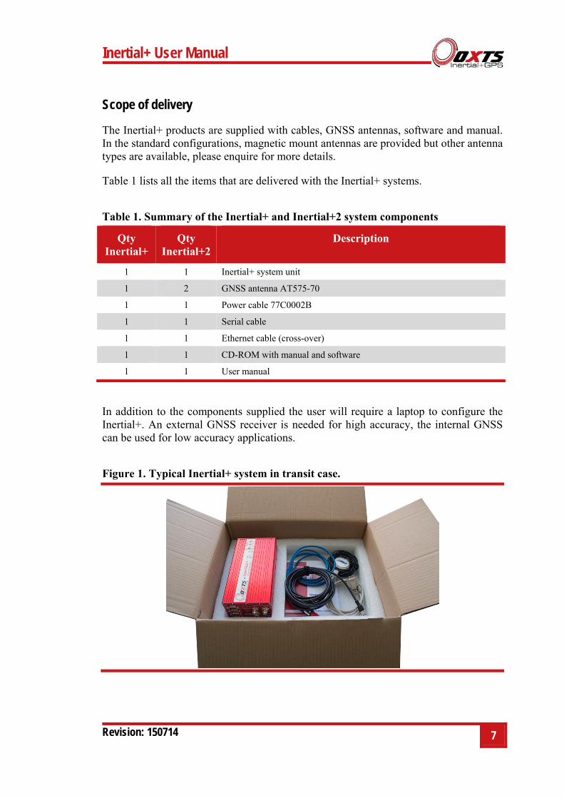
The Inertial+ products are supplied with cables, GNSS antennas, software and manual. In the standard configurations, magnetic mount antennas are provided but other antenna types are available, please enquire for more details.
Table 1 lists all the items that are delivered with the Inertial+ systems.
Table 1. Summary of the Inertial+ and Inertial+2 system components
Qty Inertial+
Qty Inertial+2
Description
1 1 Inertial+ system unit
1 2 GNSS antenna AT575-70
1 1 Power cable 77C0002B
1 1 Serial cable
1 1 Ethernet cable (cross-over)
1 1 CD-ROM with manual and software
1 1 User manual
In addition to the components supplied the user will require a laptop to configure the Inertial+. An external GNSS receiver is needed for high accuracy, the internal GNSS can be used for low accuracy applications.
Figure 1. Typical Inertial+ system in transit case.
8 Oxford Technical Solutions
Introduction
The Inertial+ is an add-on for GNSS receivers to improve reliability and accuracy. The Inertial+ uses accelerometers and angular rate sensors (gyros) to smooth the jumps in GNSS and fill in missing data. Other important measurements, such as heading, pitch and roll, can also be measured.
The Inertial+ is a true inertial navigation system (INS) that is aided by the external GNSS. An inertial sensor block with three accelerometers and three angular rate sensors is used to compute all the outputs. A WGS 84 modelled strapdown navigator algorithm compensates for earth curvature, rotation and Coriolis accelerations while measurements from the external GNSS receiver update the position and velocity navigated by the inertial sensors.
This innovative approach gives the Inertial+ several distinct advantages over systems that use GNSS alone:
All outputs remain available continuously during GNSS blackouts when, for example, the vehicle drives under a bridge.
The Inertial+ recognises jumps in the GNSS position and ignores them.
The position and velocity measurements that the GNSS makes are smoothed to reduce the high-frequency noise.
The Inertial+ makes many measurements that GNSS cannot make, for example acceleration, angular rate, heading, pitch, roll, etc.
The Inertial+ takes inputs from a wheel speed odometer in order to improve the drift rate when no GNSS is available.
The Inertial+ has a high (100 or 250 Hz) update rate and a wide bandwidth.
The outputs are available with very low, 3.5 ms latency.
The Inertial+ system processes the data in real-time. The real-time results are output via RS232 and over 10/100 Base-T Ethernet using a UDP broadcast. Outputs are time-stamped and refer to GPS time. The measurements are synchronised to the GPS clock.
Inertial+ User Manual
Revision: 150714 9
Easy operation
Installation and operation of the Inertial+ could not be simpler. A simple configuration wizard is used to configure the Inertial+. The configuration can be saved to the Inertial+ so it can operate autonomously without user intervention. A lot of work has been put into the initialisation of the inertial algorithms so that the Inertial+ can reliably start to navigate in the vast majority of situations. For example, the Inertial+ can initialize during flight without problems.
To make installation easier, the Inertial+ contains its own, low-cost GNSS receiver. This receiver is used to synchronise the inertial measurements to the external GNSS receiver. Using this technique the Inertial+ is able to precisely time-align the measurements from the external GNSS, giving much more accurate results.
The single unit contains the inertial sensors, low-cost GNSS receiver, data storage and CPU. A laptop computer can be used to view the results in real-time. Often an antenna splitter can be used to split the signal from the external GNSS receiver and feed it to the GNSS receiver in the Inertial+.
Self-correcting
Unlike conventional inertial navigation systems, the Inertial+ uses GNSS to correct all its measurements. GNSS makes measurements of position and velocity and (for dual antenna systems) heading. Using these measurements the Inertial+ is able to keep other quantities, such as roll, pitch and heading, accurate. Tight coupling of the GNSS and inertial measurements means the raw GNSS data can also be used.
Flexible accuracy
The Inertial+ takes GNSS accuracy measurements into account and uses them to obtain the best possible output accuracy. When using a 1 cm accurate GNSS receiver the Inertial+ will give 1 cm accurate results. The Inertial+ can also be used without the need for an external GNSS receiver and still provide an accurate navigation solution using its own internal receivers.
Drop-in component
The Inertial+ has been made so that it is a “drop-in” component in many applications. The NMEA input and NMEA output means that the original GNSS output can be connected to the Inertial+ and the Inertial+ output can be connected to the final application.
10 Oxford Technical Solutions
Related documents
This manual contains sufficient information about the installation and operation of an Inertial+ system. It is beyond the scope of this manual to provide details on service or repair. Contact OxTS support or your local representative for any customer service related inquiries.
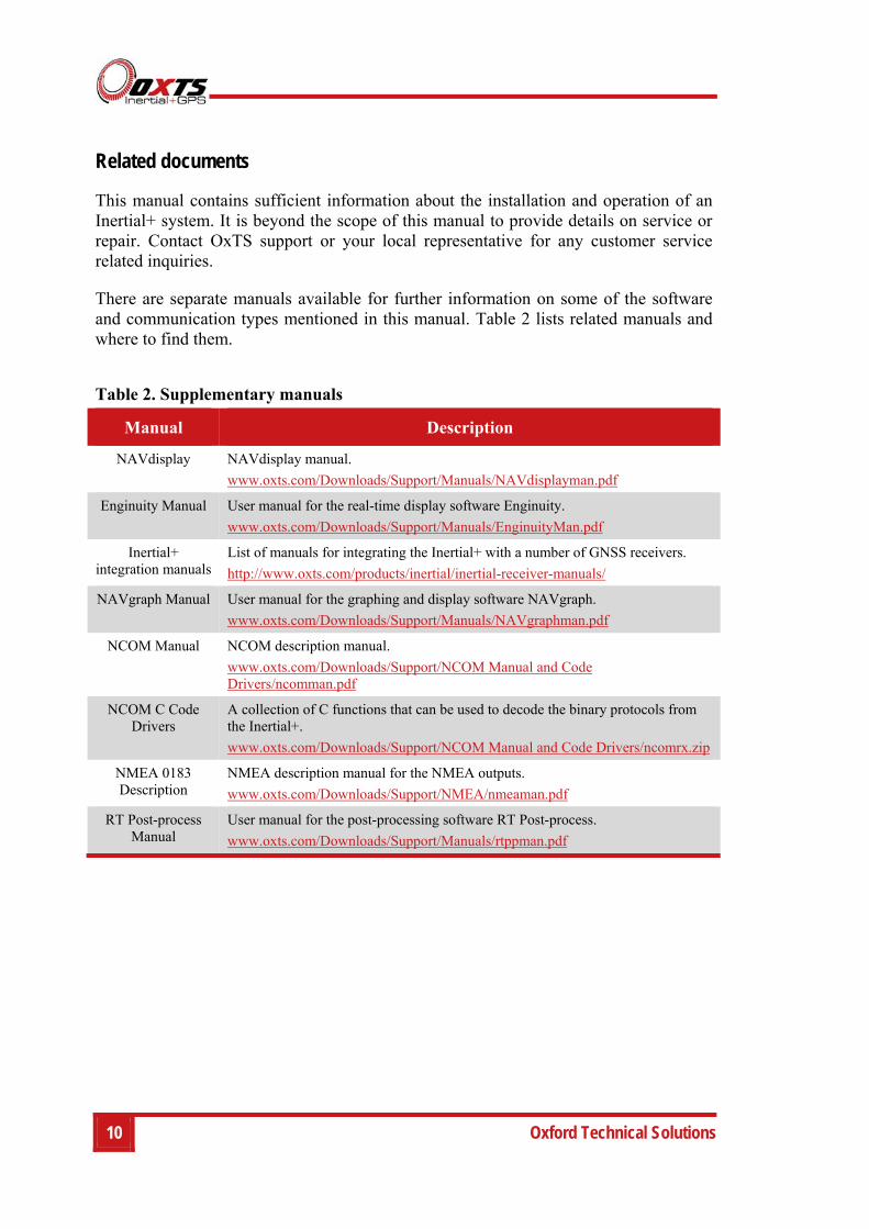
There are separate manuals available for further information on some of the software and communication types mentioned in this manual. Table 2 lists related manuals and where to find them.
Table 2. Supplementary manuals
Manual Description
NAVdisplay NAVdisplay manual.
www.oxts.com/Downloads/Support/Manuals/NAVdisplayman.pdf
Enginuity Manual User manual for the real-time display software Enginuity.
www.oxts.com/Downloads/Support/Manuals/EnginuityMan.pdf
Inertial+ integration manuals
List of manuals for integrating the Inertial+ with a number of GNSS receivers.
http://www.oxts.com/products/inertial/inertial-receiver-manuals/
NAVgraph Manual User manual for the graphing and display software NAVgraph.
www.oxts.com/Downloads/Support/Manuals/NAVgraphman.pdf
NCOM Manual NCOM description manual.
www.oxts.com/Downloads/Support/NCOM Manual and Code Drivers/ncomman.pdf
NCOM C Code Drivers
A collection of C functions that can be used to decode the binary protocols from the Inertial+.
www.oxts.com/Downloads/Support/NCOM Manual and Code Drivers/ncomrx.zip
NMEA 0183 Description
NMEA description manual for the NMEA outputs.
www.oxts.com/Downloads/Support/NMEA/nmeaman.pdf
RT Post-process Manual
User manual for the post-processing software RT Post-process.
www.oxts.com/Downloads/Support/Manuals/rtppman.pdf
Inertial+ User Manual
Revision: 150714 11
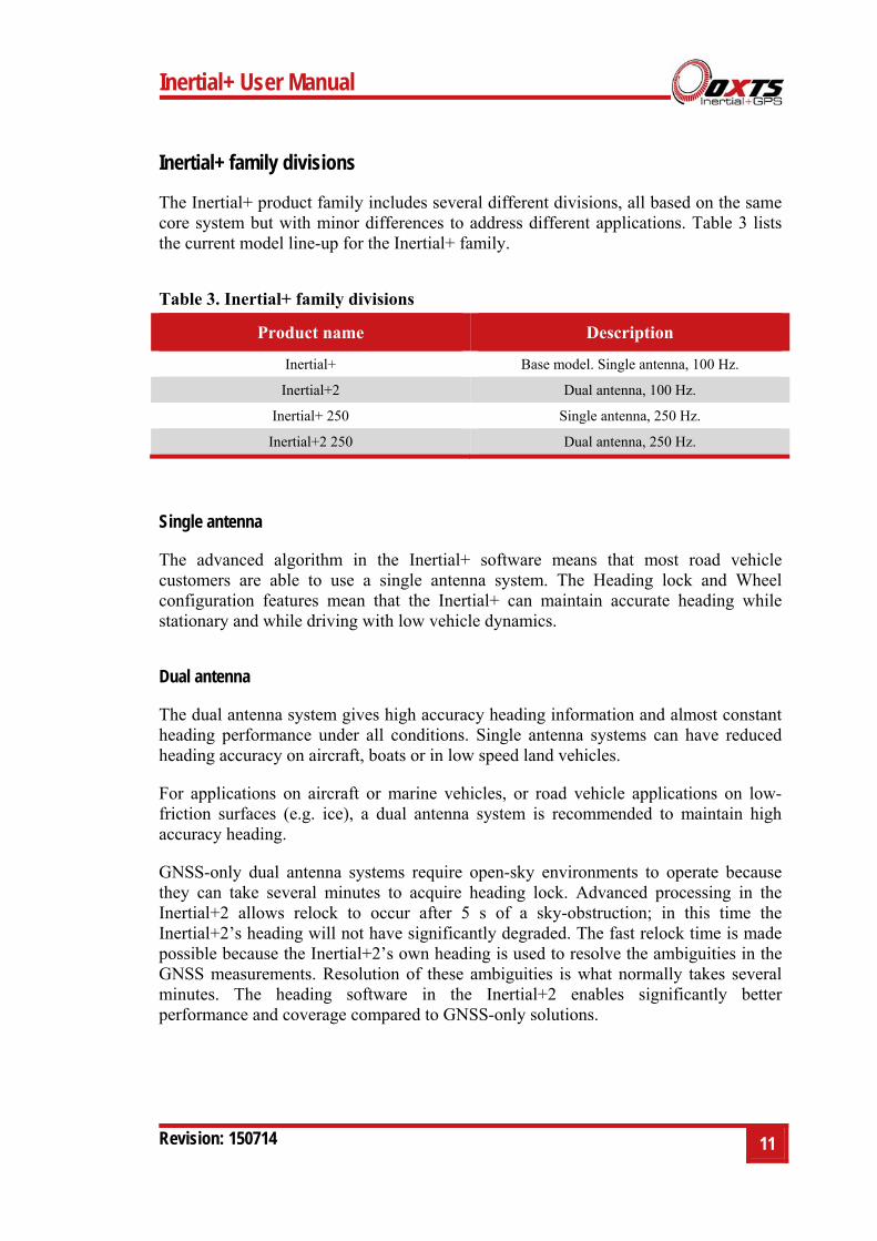
Inertial+ family divisions
The Inertial+ product family includes several different divisions, all based on the same core system but with minor differences to address different applications. Table 3 lists the current model line-up for the Inertial+ family.
Table 3. Inertial+ family divisions
Product name Description
Inertial+ Base model. Single antenna, 100 Hz.
Inertial+2 Dual antenna, 100 Hz.
Inertial+ 250 Single antenna, 250 Hz.
Inertial+2 250 Dual antenna, 250 Hz.
Single antenna
The advanced algorithm in the Inertial+ software means that most road vehicle customers are able to use a single antenna system. The Heading lock and Wheel configuration features mean that the Inertial+ can maintain accurate heading while stationary and while driving with low vehicle dynamics.
Dual antenna
The dual antenna system gives high accuracy heading information and almost constant heading performance under all conditions. Single antenna systems can have reduced heading accuracy on aircraft, boats or in low speed land vehicles.
For applications on aircraft or marine vehicles, or road vehicle applications on low-friction surfaces (e.g. ice), a dual antenna system is recommended to maintain high accuracy heading.
GNSS-only dual antenna systems require open-sky environments to operate because they can take several minutes to acquire heading lock. Advanced processing in the Inertial+2 allows relock to occur after 5 s of a sky-obstruction; in this time the Inertial+2’s heading will not have significantly degraded. The fast relock time is made possible because the Inertial+2’s own heading is used to resolve the ambiguities in the GNSS measurements. Resolution of these ambiguities is what normally takes several minutes. The heading software in the Inertial+2 enables significantly better performance and coverage compared to GNSS-only solutions.

12 Oxford Technical Solutions
250 Hz
Both the Inertial+ and Inertial+2 have the option of coming with a 250 Hz version of the inertial measurement unit (IMU). The IMUs used in 100 Hz and 250 Hz products are essentially the same, both with a fundamental sampling frequency of 2500 Hz. The difference is the 3D filter used to integrate the accelerations and angular rates has a smaller time step in the 250 Hz version, allowing a higher update rate.
However, because of the smaller time step, measurements that depend on angular acceleration are typically noisier on the 250 Hz products. The noise can be managed by filtering the data to limit the bandwidth.
Inertial+ User Manual
Revision: 150714 13
Specification
The specification of the Inertial+ depends on the GNSS receiver connected. Typical figures are listed in Table 4. These specifications are listed for operation of the system under the following conditions:
After a warm-up period of 15 minutes continuous operation.
Open sky environment, free from cover by trees, bridges, buildings or other obstructions. The vehicle must have remained in open sky for at least 5 minutes for full accuracy.
The vehicle must exhibit some motion behaviour. Accelerations of the unit in different directions are required so that the Kalman filter can estimate the errors in the sensors. Without this estimation some of the specifications degrade.
The distance from the system to the external GNSS antenna must be known by the system to a precision of 5 mm or better. The vibration of the system relative to the vehicle cannot allow this to change by more than 5 mm. The system can estimate this value itself in some dynamic conditions.
The heading accuracy is only achieved under dynamic conditions. Under slow and static conditions the performance will degrade.
14 Oxford Technical Solutions
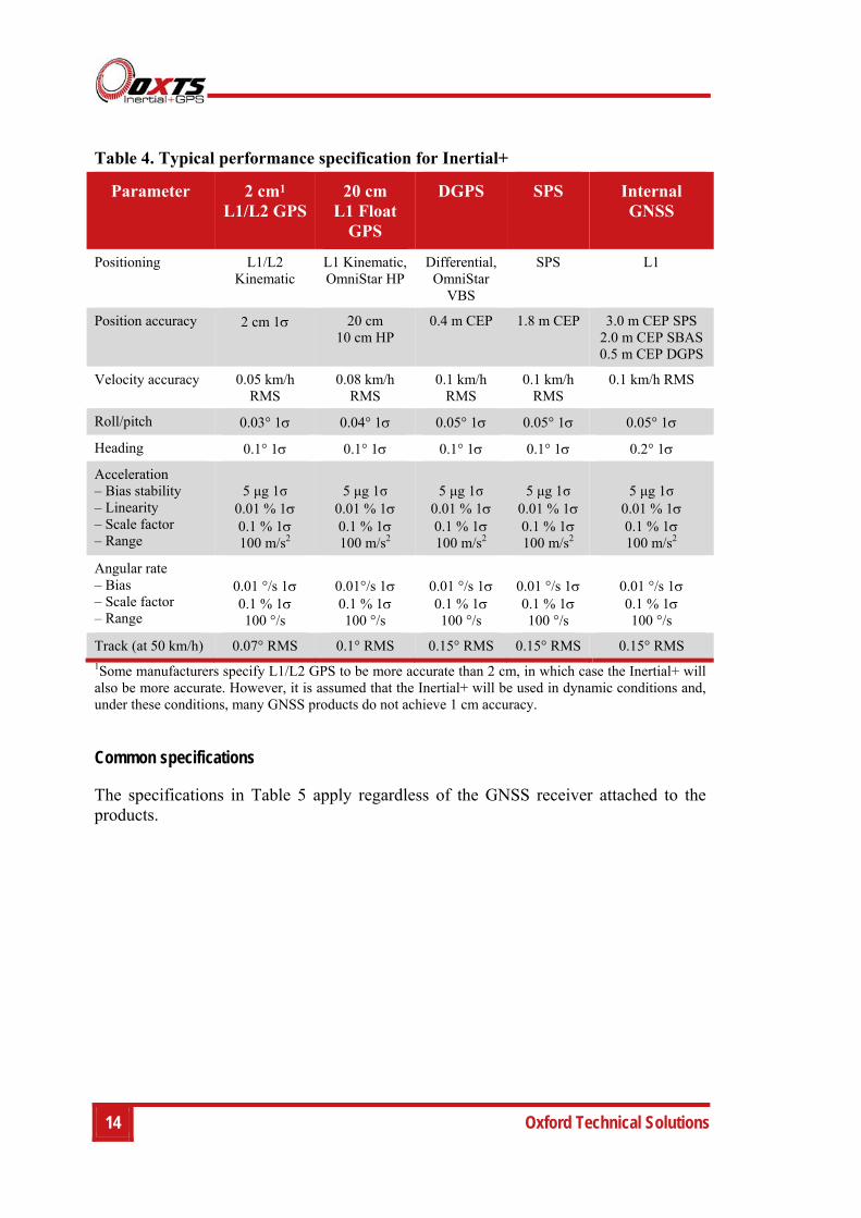
Table 4. Typical performance specification for Inertial+
Parameter 2 cm1 L1/L2 GPS
20 cm L1 Float
GPS
DGPS SPS Internal GNSS
Positioning L1/L2 Kinematic
L1 Kinematic,OmniStar HP
Differential,OmniStar
VBS
SPS L1
Position accuracy 2 cm 1 20 cm 10 cm HP
0.4 m CEP 1.8 m CEP 3.0 m CEP SPS 2.0 m CEP SBAS 0.5 m CEP DGPS
Velocity accuracy 0.05 km/h RMS
0.08 km/h RMS
0.1 km/h RMS
0.1 km/h RMS
0.1 km/h RMS
Roll/pitch 0.03° 1 0.04° 1 0.05° 1 0.05° 1 0.05° 1
Heading 0.1° 1 0.1° 1 0.1° 1 0.1° 1 0.2° 1
Acceleration – Bias stability – Linearity – Scale factor – Range
5 μg 1σ
0.01 % 1 0.1 % 1 100 m/s2
5 μg 1σ
0.01 % 1 0.1 % 1 100 m/s2
5 μg 1σ
0.01 % 1 0.1 % 1 100 m/s2
5 μg 1σ
0.01 % 10.1 % 1 100 m/s2
5 μg 1σ
0.01 % 1 0.1 % 1 100 m/s2
Angular rate – Bias – Scale factor – Range
0.01 °/s 1 0.1 % 1 100 °/s
0.01°/s 1 0.1 % 1 100 °/s
0.01 °/s 1 0.1 % 1 100 °/s
0.01 °/s 10.1 % 1 100 °/s
0.01 °/s 1 0.1 % 1 100 °/s
Track (at 50 km/h) 0.07° RMS 0.1° RMS 0.15° RMS 0.15° RMS 0.15° RMS 1Some manufacturers specify L1/L2 GPS to be more accurate than 2 cm, in which case the Inertial+ will also be more accurate. However, it is assumed that the Inertial+ will be used in dynamic conditions and, under these conditions, many GNSS products do not achieve 1 cm accuracy.
Common specifications
The specifications in Table 5 apply regardless of the GNSS receiver attached to the products.
Inertial+ User Manual
Revision: 150714 15
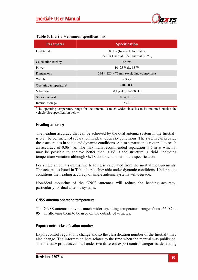
Table 5. Inertial+ common specifications
Parameter Specification
Update rate 100 Hz (Inertial+, Inertial+2)
250 Hz (Inertial+ 250, Inertial+2 250)
Calculation latency 3.5 ms
Power 10–25 V dc, 15 W
Dimensions 234 × 120 × 76 mm (excluding connectors)
Weight 2.3 kg
Operating temperature1 -10–50°C
Vibration 0.1 g²/Hz, 5–500 Hz
Shock survival 100 g, 11 ms
Internal storage 2 GB 1The operating temperature range for the antenna is much wider since it can be mounted outside the vehicle. See specification below.
Heading accuracy
The heading accuracy that can be achieved by the dual antenna system in the Inertial+ is 0.2° 1 per meter of separation in ideal, open sky conditions. The system can provide these accuracies in static and dynamic conditions. A 4 m separation is required to reach an accuracy of 0.06° 1σ. The maximum recommended separation is 5 m at which it may be possible to achieve better than 0.06° if the structure is rigid, including temperature variation although OxTS do not claim this in the specification.
For single antenna systems, the heading is calculated from the inertial measurements. The accuracies listed in Table 4 are achievable under dynamic conditions. Under static conditions the heading accuracy of single antenna systems will degrade.
Non-ideal mounting of the GNSS antennas will reduce the heading accuracy, particularly for dual antenna systems.
GNSS antenna operating temperature
The GNSS antennas have a much wider operating temperature range, from -55 °C to 85 °C, allowing them to be used on the outside of vehicles.
Export control classification number
Export control regulations change and so the classification number of the Inertial+ may also change. The information here relates to the time when the manual was published. The Inertial+ products can fall under two different export control categories, depending
16 Oxford Technical Solutions
on the type of accelerometer fitted internally. The type of accelerometer does not affect the specification of the product, only the export control classification number (ECCN).
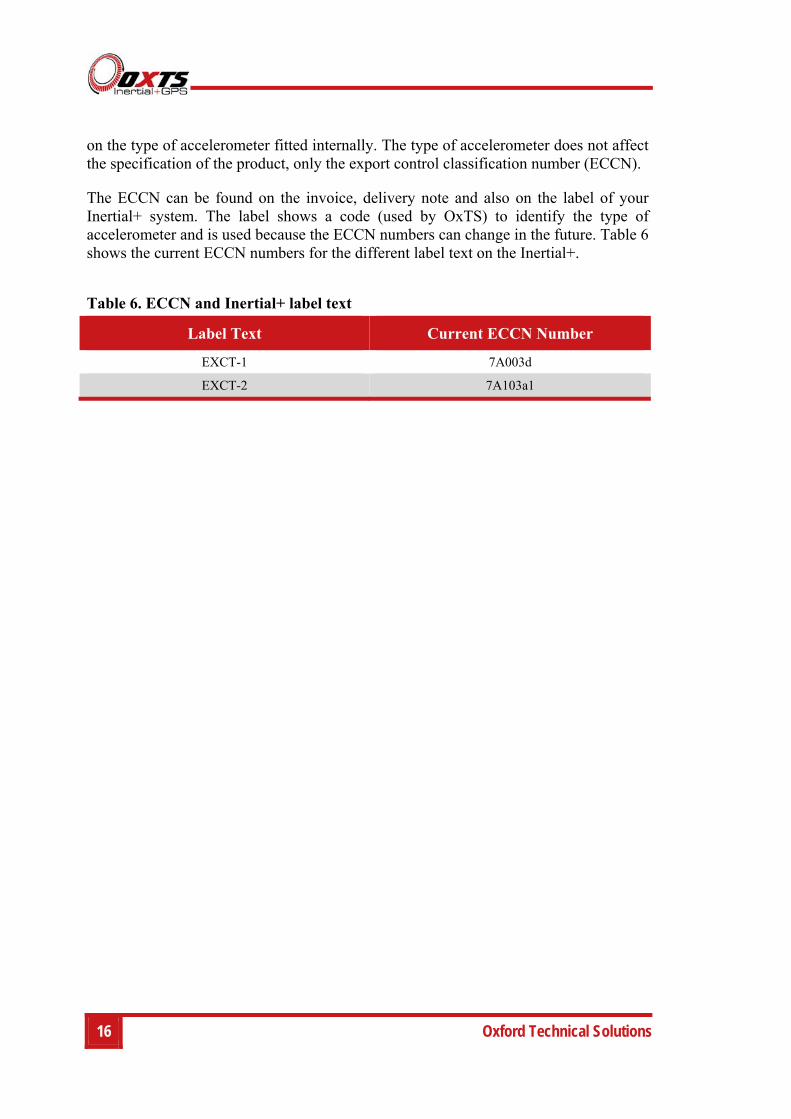
The ECCN can be found on the invoice, delivery note and also on the label of your Inertial+ system. The label shows a code (used by OxTS) to identify the type of accelerometer and is used because the ECCN numbers can change in the future. Table 6 shows the current ECCN numbers for the different label text on the Inertial+.
Table 6. ECCN and Inertial+ label text
Label Text Current ECCN Number
EXCT-1 7A003d
EXCT-2 7A103a1
Inertial+ User Manual
Revision: 150714 17
Conformance notices
The Inertial+ complies with the radiated emission limits for 47CFR15.109:2010 class A of Part 15 subpart B of the FCC rules, and with the emission and immunity limits for class A of EN 55022. These limits are designed to provide reasonable protection against harmful interference in business, commercial and industrial uses. This equipment generates, uses and can radiate radio frequency energy and, if not installed and used in accordance with the instructions, may cause harmful interference to radio communications. However, there is no guarantee that interference will not occur in a particular installation. If this equipment does cause harmful interference to radio or television reception, which can be determined by turning the equipment off and on, the user is encouraged to try to correct the interference by one or more of the following measures:
Re-orient or relocate the receiving antenna
Increase the separation between the equipment and the receiver
The Inertial+ incorporates a GPS receiver. Any GPS receiver will not be able to track satellites in the presence of strong RF radiations within 70 MHz of the L1 GPS frequency (1575 MHz).
The Inertial+ conforms to the requirements for CE.
Any use or misuse of the Inertial+ in a manner not intended may impair the protection provided. OxTS is not liable for any damages caused by the misuse of the equipment.
Regulator testing standards
47CFR15.109:2010 class A (radiated emissions)
EN 300 440-1:2008, test methods 8.3.2 (conducted emissions) and 8.3.3 (radiated emissions)
EN 55022 class A according to standard EN 301 489-1:2008 (conducted emissions)
EN6100-4-3 criterion A according to standard EN 301 489-1:2008 (radiated immunity)
ISO7637-2 criterion B, 12V according to standard EN 301 489-1:2008 (vehicular transients and surges immunity). Older Inertial+ systems do not conform to this standard, contact OxTS for further details.
EN 60950-1:2006 (safety)

18 Oxford Technical Solutions
A11:2009 (safety)
Inertial+ User Manual
Revision: 150714 19
Software installation
Included with every Inertial+ is a CD containing the software package NAVsuite. This package contains a number of programs required to take full advantage of the Inertial+’s capabilities. Table 7 lists the contents of NAVsuite.
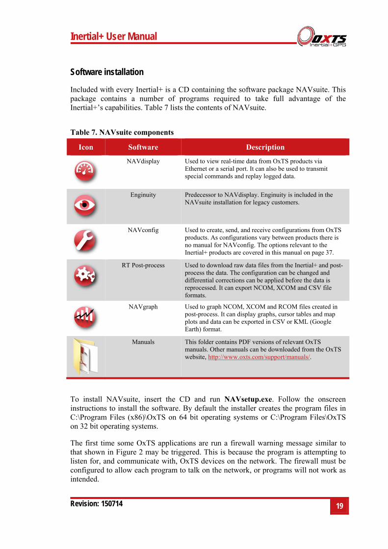
Table 7. NAVsuite components
Icon Software Description
NAVdisplay Used to view real-time data from OxTS products via Ethernet or a serial port. It can also be used to transmit special commands and replay logged data.
Enginuity Predecessor to NAVdisplay. Enginuity is included in the NAVsuite installation for legacy customers.
NAVconfig Used to create, send, and receive configurations from OxTS products. As configurations vary between products there is no manual for NAVconfig. The options relevant to the Inertial+ products are covered in this manual on page 37.
RT Post-process Used to download raw data files from the Inertial+ and post-process the data. The configuration can be changed and differential corrections can be applied before the data is reprocessed. It can export NCOM, XCOM and CSV file formats.
NAVgraph Used to graph NCOM, XCOM and RCOM files created in post-process. It can display graphs, cursor tables and map plots and data can be exported in CSV or KML (Google Earth) format.
Manuals This folder contains PDF versions of relevant OxTS manuals. Other manuals can be downloaded from the OxTS website, http://www.oxts.com/support/manuals/.
To install NAVsuite, insert the CD and run NAVsetup.exe. Follow the onscreen instructions to install the software. By default the installer creates the program files in C:\Program Files (x86)\OxTS on 64 bit operating systems or C:\Program Files\OxTS on 32 bit operating systems.
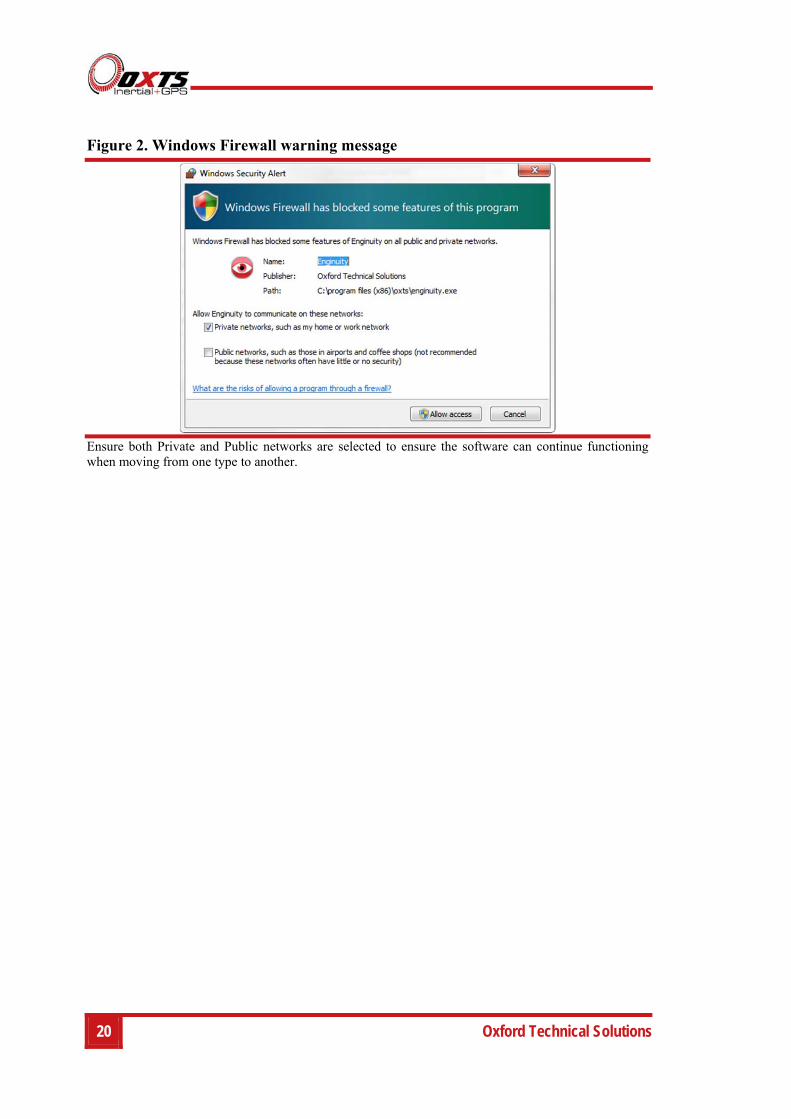
The first time some OxTS applications are run a firewall warning message similar to that shown in Figure 2 may be triggered. This is because the program is attempting to listen for, and communicate with, OxTS devices on the network. The firewall must be configured to allow each program to talk on the network, or programs will not work as intended.
20 Oxford Technical Solutions
Figure 2. Windows Firewall warning message
Ensure both Private and Public networks are selected to ensure the software can continue functioning when moving from one type to another.
Inertial+ User Manual
Revision: 150714 21
Connections
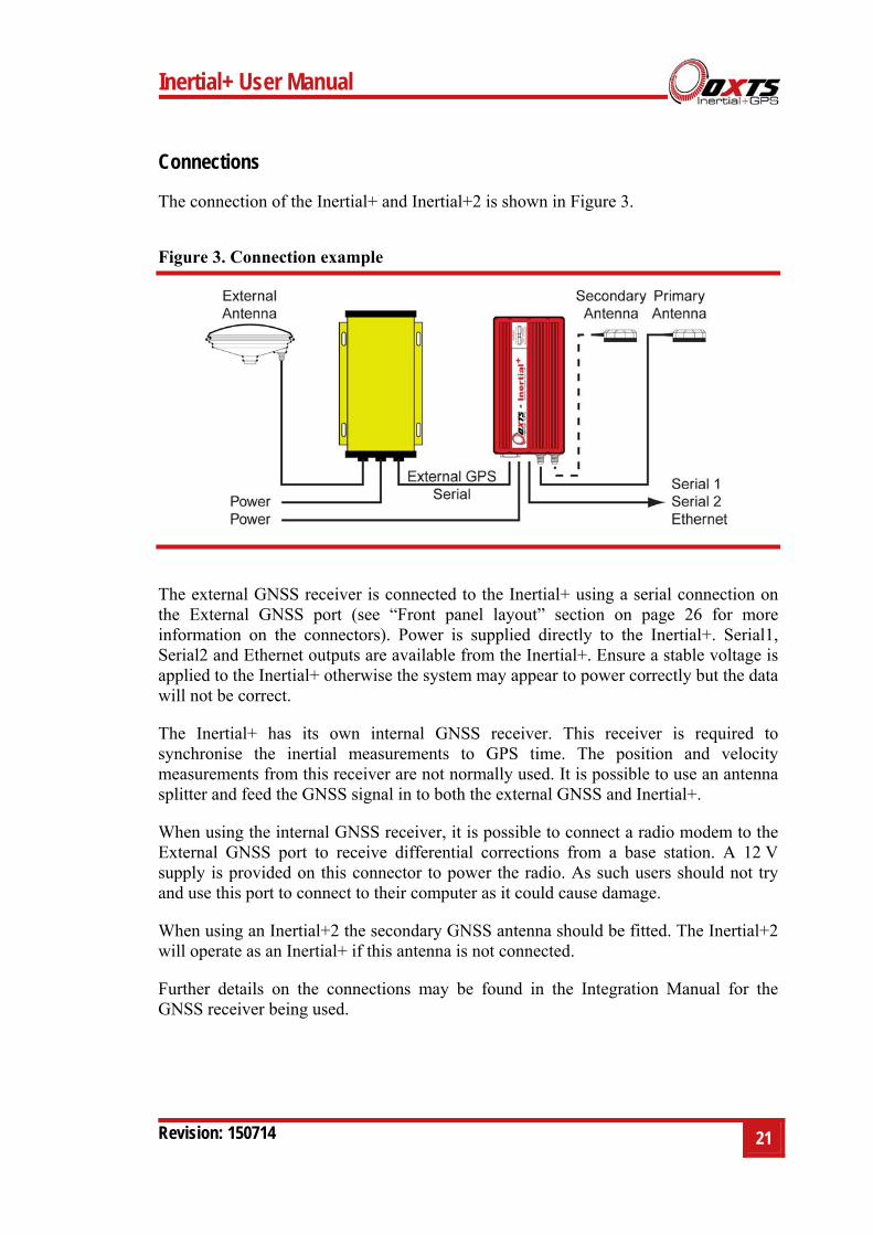
The connection of the Inertial+ and Inertial+2 is shown in Figure 3.
Figure 3. Connection example
The external GNSS receiver is connected to the Inertial+ using a serial connection on the External GNSS port (see “Front panel layout” section on page 26 for more information on the connectors). Power is supplied directly to the Inertial+. Serial1, Serial2 and Ethernet outputs are available from the Inertial+. Ensure a stable voltage is applied to the Inertial+ otherwise the system may appear to power correctly but the data will not be correct.
The Inertial+ has its own internal GNSS receiver. This receiver is required to synchronise the inertial measurements to GPS time. The position and velocity measurements from this receiver are not normally used. It is possible to use an antenna splitter and feed the GNSS signal in to both the external GNSS and Inertial+.
When using the internal GNSS receiver, it is possible to connect a radio modem to the External GNSS port to receive differential corrections from a base station. A 12 V supply is provided on this connector to power the radio. As such users should not try and use this port to connect to their computer as it could cause damage.
When using an Inertial+2 the secondary GNSS antenna should be fitted. The Inertial+2 will operate as an Inertial+ if this antenna is not connected.
Further details on the connections may be found in the Integration Manual for the GNSS receiver being used.
22 Oxford Technical Solutions
Hardware installation
It is essential to install the Inertial+ rigidly in the vehicle. The Inertial+ should not be able to move or rotate compared to either GNSS antenna, otherwise the performance will be reduced.
In most circumstances the Inertial+ should be mounted directly to the chassis of the vehicle. If the vehicle experiences high shocks then vibration mounts may be required.
The Inertial+ is compatible with the RT-Strut product from OxTS, which can be used to provide a quick and secure vehicle mounting option.
Do not install the Inertial+ where it is in direct sunlight which, in hot countries, may cause the case to exceed the maximum temperature specification.
For single antenna installations, the position of the primary GNSS antenna is not critical; it can have a partial view of the sky as long as it has enough satellites to operate.
For dual antenna installations it is essential for both the primary and the secondary antenna to be mounted in a good, open location and on a suitable ground plane such as the roof of a vehicle. The antennas cannot be mounted on non-conducting materials or near the edges of conducting materials. If the antennas are to be mounted with no conductor below them then different antennas must be used.
Inertial+ orientation and alignment
The orientation of the Inertial+ in the vehicle is normally specified using three consecutive rotations that rotate the Inertial+ to the vehicle’s co-ordinate frame. The order of the rotations is heading (z-axis rotation), then pitch (y-axis rotation), then roll (x-axis rotation). The Inertial+ co-ordinate conventions are detailed on page 29. It is important to get the order of the rotations correct.
In the default configuration the Inertial+ expects its y-axis to be pointing right and its z-axis pointing down relative to the host vehicle. There are times however when installing an Inertial+ in the default configuration is not possible, for example when using the RT-Strut. The Inertial+ can be mounted at any angle in the vehicle as long as the configuration is described to the Inertial+ using NAVconfig. This allows the outputs to be rotated based on the settings entered to transform the measurements to the vehicle frame.
For ease of use it is best to try and mount the Inertial+ so its axes are aligned with the vehicle axes. This saves the offsets having to be measured by the user. If the system must be mounted misaligned with the vehicle and the user cannot accurately measure the angle offsets, the Inertial+ has some functions to measure these offsets itself. The heading offset can be measured if the vehicle has a non-steered axle. The Wheel
Inertial+ User Manual
Revision: 150714 23
configuration and Improve configuration utilities should be used for this (see pages 52 and 47 respectively). Roll and pitch offsets can be measured using the Surface tilt utility in Enginuity.
Antenna placement and orientation
For optimal performance it is essential for the GNSS antenna(s) to be mounted where they have a clear, uninterrupted view of the sky and on a suitable ground plane, such as the roof of a vehicle. For good multipath rejection the antennas must be mounted on a metal surface using the magnetic mounts provided; no additional gap may be used.
The antennas cannot be mounted on non-conducting materials or near the edges of conducting materials. If the antennas are to be mounted with no conductor below them then different antennas must be used. It is recommended to mount the antennas at least 30 cm from any edge where possible.
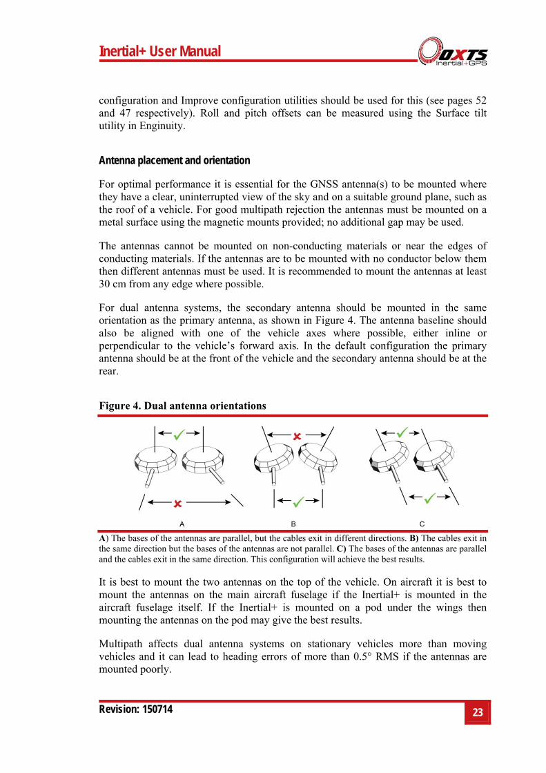
For dual antenna systems, the secondary antenna should be mounted in the same orientation as the primary antenna, as shown in Figure 4. The antenna baseline should also be aligned with one of the vehicle axes where possible, either inline or perpendicular to the vehicle’s forward axis. In the default configuration the primary antenna should be at the front of the vehicle and the secondary antenna should be at the rear.
Figure 4. Dual antenna orientations
A) The bases of the antennas are parallel, but the cables exit in different directions. B) The cables exit in the same direction but the bases of the antennas are not parallel. C) The bases of the antennas are parallel and the cables exit in the same direction. This configuration will achieve the best results.
It is best to mount the two antennas on the top of the vehicle. On aircraft it is best to mount the antennas on the main aircraft fuselage if the Inertial+ is mounted in the aircraft fuselage itself. If the Inertial+ is mounted on a pod under the wings then mounting the antennas on the pod may give the best results.
Multipath affects dual antenna systems on stationary vehicles more than moving vehicles and it can lead to heading errors of more than 0.5° RMS if the antennas are mounted poorly.
24 Oxford Technical Solutions
It is critical to have the Inertial+ mounted securely in the vehicle. If the angle of the Inertial+ can change relative to the vehicle then the dual antenna system will not work correctly. This is far more critical for dual antenna systems than for single antenna systems. The user should aim to have no more than 0.05° of mounting angle change throughout the testing. (If the Inertial+ is shock mounted then the mounting will change by more than 0.05°; this is acceptable, but the hysteresis of the mounting may not exceed 0.05°).
For both single and dual antenna systems it is essential that the supplied GNSS antenna cables are used and not extended, shortened or replaced. This is even more critical for dual antenna systems and the two antenna cables must be of the same specification. Do not, for example, use a 5 m antenna cable for one antenna and a 15 m antenna cable for the other. Do not extend the cable, even using special GNSS signal repeaters that are designed to accurately repeat the GNSS signal. Cable length options are available in 5 m and 15 m lengths.
Using an antenna splitter
In many cases it is possible to use an antenna splitter with the Inertial+ so that only one antenna is needed (or two antennas for dual-antenna systems). If an antenna splitter is used then there are a few important points to consider.
The Inertial+ supplies a 5 V output to the antenna with up to 100 mA supply. This is probably enough to power both the antenna and the antenna splitter.
If the Inertial+ is supplying the power to the antenna splitter then both the antenna and the antenna splitter need to work correctly from a 5 V supply.
The Inertial+ has an extremely sensitive GNSS receiver in it. High gain antennas can sometimes have a signal that is too large for the Inertial+. Antenna splitters often contain some additional gain (to overcome cable and connector losses). Having an antenna with a gain of more than 40 dB is not recommended. This may be 35 dB for the antenna and 5 dB for the antenna splitter. Cable loss may increase the amount of gain that can be used.
In dual antenna configurations only one antenna splitter is required if the antenna splitter does not cause a significant phase change to the signal. Both antennas need to be of the same design or the dual antenna system will not work. Cable lengths should not be significantly different (e.g. 1 m on one antenna and 15 m on the other is not recommended).
OxTS has tried and tested an antenna splitter from GPS Networking in a dual antenna configuration and we could not find a reduction in the performance. The details of the product tested are listed in Table 8.
Inertial+ User Manual
Revision: 150714 25
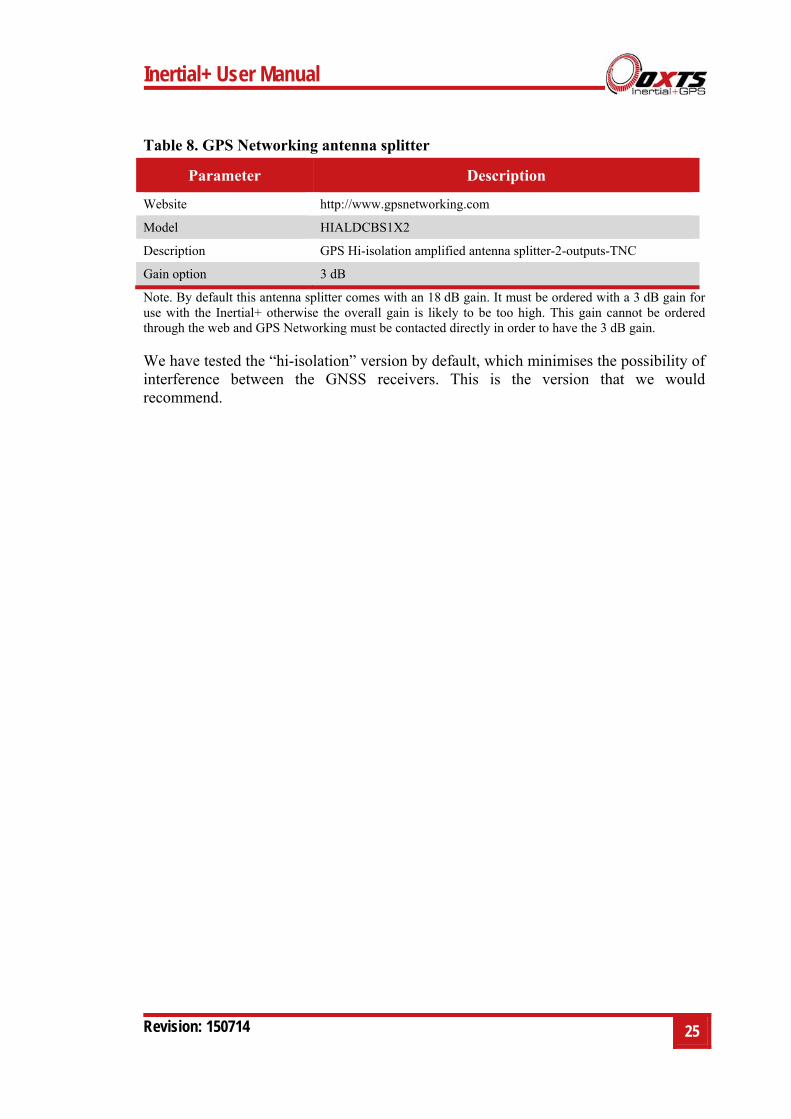
Table 8. GPS Networking antenna splitter
Parameter Description
Website http://www.gpsnetworking.com
Model HIALDCBS1X2
Description GPS Hi-isolation amplified antenna splitter-2-outputs-TNC
Gain option 3 dB
Note. By default this antenna splitter comes with an 18 dB gain. It must be ordered with a 3 dB gain for use with the Inertial+ otherwise the overall gain is likely to be too high. This gain cannot be ordered through the web and GPS Networking must be contacted directly in order to have the 3 dB gain.
We have tested the “hi-isolation” version by default, which minimises the possibility of interference between the GNSS receivers. This is the version that we would recommend.
26 Oxford Technical Solutions
Operation
The Inertial+ has been designed to be simple and easy to operate. The front panel label and LEDs convey some basic information that aid in configuration and troubleshooting. Once powered, the Inertial+ requires no further input from the user to start logging and outputting data.
This section covers some basic information required for operation of the Inertial+.
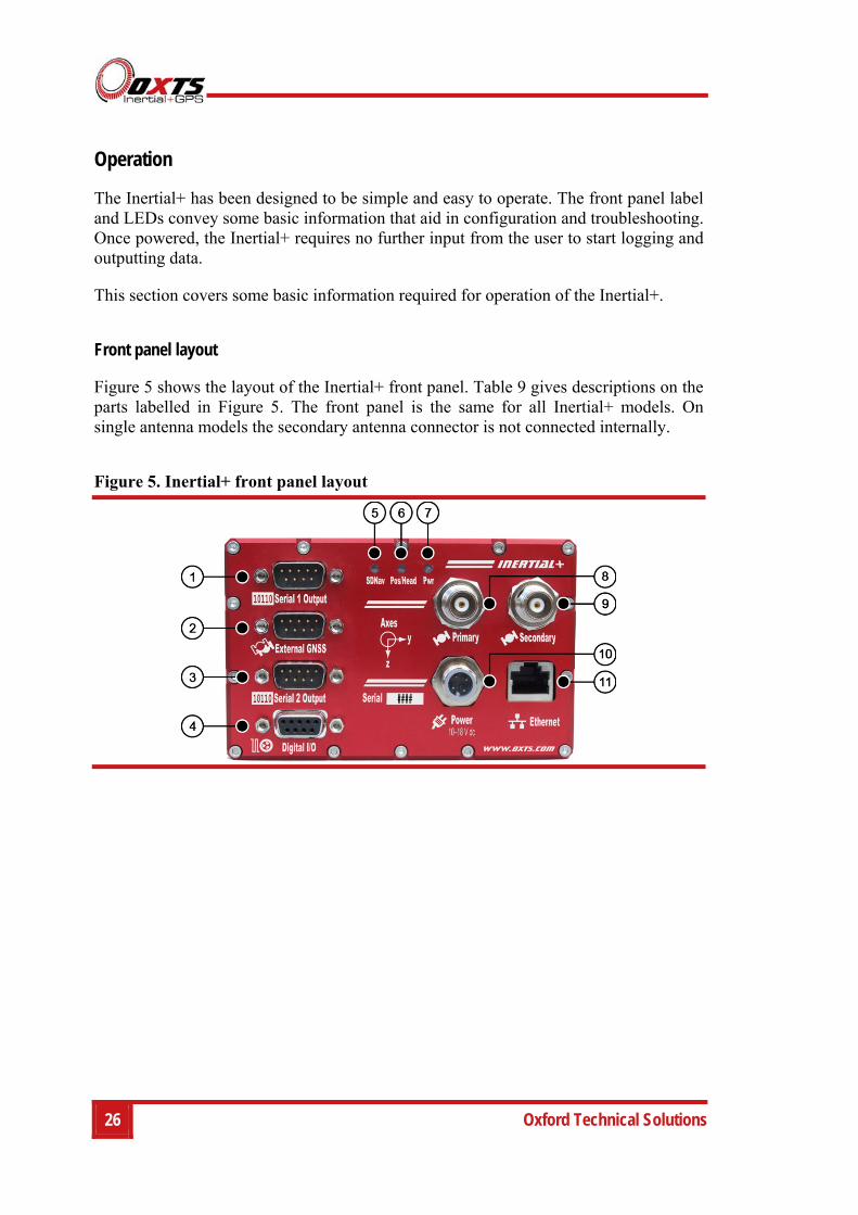
Front panel layout
Figure 5 shows the layout of the Inertial+ front panel. Table 9 gives descriptions on the parts labelled in Figure 5. The front panel is the same for all Inertial+ models. On single antenna models the secondary antenna connector is not connected internally.
Figure 5. Inertial+ front panel layout
Inertial+ User Manual
Revision: 150714 27
Table 9. Inertial+ front panel descriptions
Label no. Description
1 RS232 serial port
2 External GNSS serial port
3 Secondary RS232 serial port
4 Digital I/O port
5 SDNav LED
6 Pos/Head LED
7 Pwr LED
8 Primary antenna connector
9 Secondary antenna connector
10 M12 power connector
11 Ethernet port
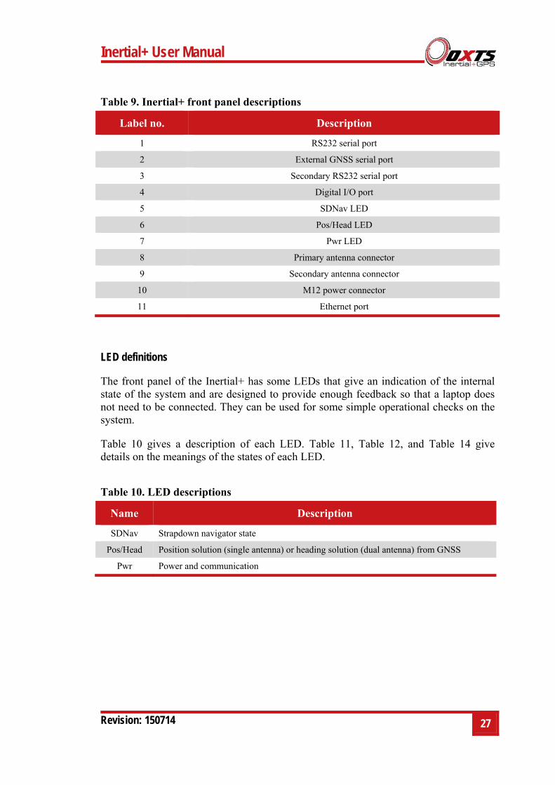
LED definitions
The front panel of the Inertial+ has some LEDs that give an indication of the internal state of the system and are designed to provide enough feedback so that a laptop does not need to be connected. They can be used for some simple operational checks on the system.
Table 10 gives a description of each LED. Table 11, Table 12, and Table 14 give details on the meanings of the states of each LED.
Table 10. LED descriptions
Name Description
SDNav Strapdown navigator state
Pos/Head Position solution (single antenna) or heading solution (dual antenna) from GNSS
Pwr Power and communication
28 Oxford Technical Solutions
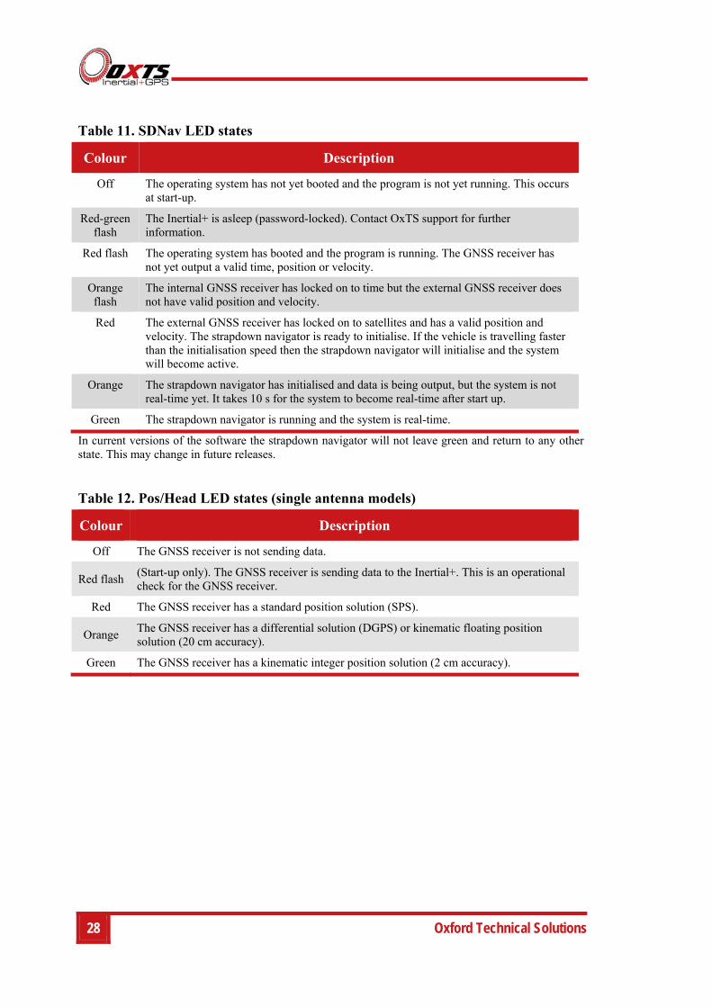
Table 11. SDNav LED states
Colour Description
Off The operating system has not yet booted and the program is not yet running. This occurs at start-up.
Red-green flash
The Inertial+ is asleep (password-locked). Contact OxTS support for further information.
Red flash The operating system has booted and the program is running. The GNSS receiver has not yet output a valid time, position or velocity.
Orange flash
The internal GNSS receiver has locked on to time but the external GNSS receiver does not have valid position and velocity.
Red The external GNSS receiver has locked on to satellites and has a valid position and velocity. The strapdown navigator is ready to initialise. If the vehicle is travelling faster than the initialisation speed then the strapdown navigator will initialise and the system will become active.
Orange The strapdown navigator has initialised and data is being output, but the system is not real-time yet. It takes 10 s for the system to become real-time after start up.
Green The strapdown navigator is running and the system is real-time.
In current versions of the software the strapdown navigator will not leave green and return to any other state. This may change in future releases.
Table 12. Pos/Head LED states (single antenna models)
Colour Description
Off The GNSS receiver is not sending data.
Red flash (Start-up only). The GNSS receiver is sending data to the Inertial+. This is an operational check for the GNSS receiver.
Red The GNSS receiver has a standard position solution (SPS).
Orange The GNSS receiver has a differential solution (DGPS) or kinematic floating position solution (20 cm accuracy).
Green The GNSS receiver has a kinematic integer position solution (2 cm accuracy).
Inertial+ User Manual
Revision: 150714 29
Table 13. Pos/Head LED states (dual antenna models)
Colour Description
Off GNSS receiver fault (valid only after start-up).
Red flash GNSS receiver is active, but has been unable to determine heading.
Red The GNSS has a differential heading lock.
Orange The GNSS receiver has a floating (poor) calibrated heading lock.
Green The GNSS receiver has an integer (good) calibrated heading lock.
Table 14. Pwr LED states
Colour Description
Off There is no power to the system or the system power-supply has failed.
Green The 5 V power supply for the system is active.
Orange The system is outputting data on the Serial 1 Output connector.
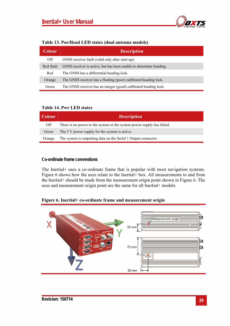
Co-ordinate frame conventions
The Inertial+ uses a co-ordinate frame that is popular with most navigation systems. Figure 6 shows how the axes relate to the Inertial+ box. All measurements to and from the Inertial+ should be made from the measurement origin point shown in Figure 6. The axes and measurement origin point are the same for all Inertial+ models.
Figure 6. Inertial+ co-ordinate frame and measurement origin
30 Oxford Technical Solutions
Table 15 lists the directions that the axes should point for zero heading, pitch and roll outputs when the default mounting orientation is used.
Table 15. Direction of axes for zero heading, pitch and roll outputs
Axis Direction Vehicle axis
x North Forward
y East Right
z Down Down
If the axes of the Inertial+ and the vehicle axes are not the same as those listed in Table 15, then they can be aligned by reconfiguring the Inertial+ for a different mounting orientation using the NAVconfig software.
If the RT-Strut is being used to mount the Inertial+ in the vehicle then NAVconfig will have to be used to configure the orientation or the Inertial+ will not work correctly. Page 45 gives more information on configuring the orientation of the Inertial+ in a vehicle.
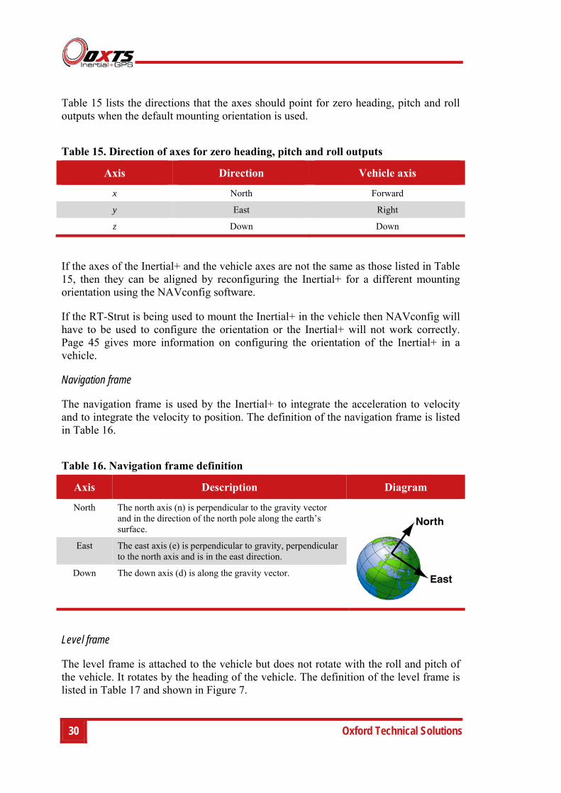
Navigation frame
The navigation frame is used by the Inertial+ to integrate the acceleration to velocity and to integrate the velocity to position. The definition of the navigation frame is listed in Table 16.
Table 16. Navigation frame definition
Axis Description Diagram
North The north axis (n) is perpendicular to the gravity vector and in the direction of the north pole along the earth’s surface.
East The east axis (e) is perpendicular to gravity, perpendicular to the north axis and is in the east direction.
Down The down axis (d) is along the gravity vector.
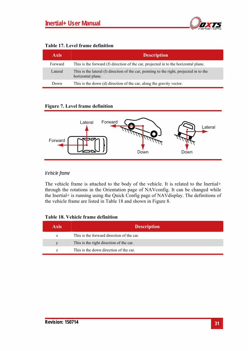
Level frame
The level frame is attached to the vehicle but does not rotate with the roll and pitch of the vehicle. It rotates by the heading of the vehicle. The definition of the level frame is listed in Table 17 and shown in Figure 7.
Inertial+ User Manual
Revision: 150714 31
Table 17. Level frame definition
Axis Description
Forward This is the forward (f) direction of the car, projected in to the horizontal plane.
Lateral This is the lateral (l) direction of the car, pointing to the right, projected in to the horizontal plane.
Down This is the down (d) direction of the car, along the gravity vector.
Figure 7. Level frame definition
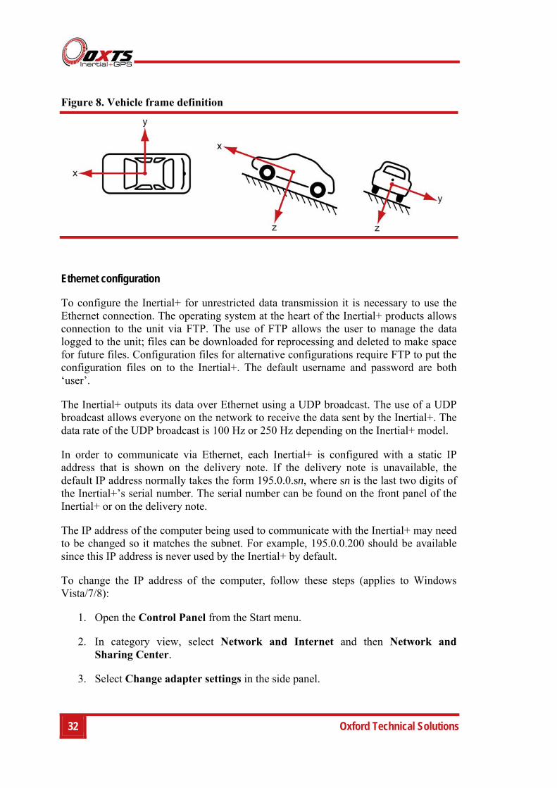
Vehicle frame
The vehicle frame is attached to the body of the vehicle. It is related to the Inertial+ through the rotations in the Orientation page of NAVconfig. It can be changed while the Inertial+ is running using the Quick Config page of NAVdisplay. The definitions of the vehicle frame are listed in Table 18 and shown in Figure 8.
Table 18. Vehicle frame definition
Axis Description
x This is the forward direction of the car.
y This is the right direction of the car.
z This is the down direction of the car.
32 Oxford Technical Solutions
Figure 8. Vehicle frame definition
Ethernet configuration
To configure the Inertial+ for unrestricted data transmission it is necessary to use the Ethernet connection. The operating system at the heart of the Inertial+ products allows connection to the unit via FTP. The use of FTP allows the user to manage the data logged to the unit; files can be downloaded for reprocessing and deleted to make space for future files. Configuration files for alternative configurations require FTP to put the configuration files on to the Inertial+. The default username and password are both ‘user’.
The Inertial+ outputs its data over Ethernet using a UDP broadcast. The use of a UDP broadcast allows everyone on the network to receive the data sent by the Inertial+. The data rate of the UDP broadcast is 100 Hz or 250 Hz depending on the Inertial+ model.
In order to communicate via Ethernet, each Inertial+ is configured with a static IP address that is shown on the delivery note. If the delivery note is unavailable, the default IP address normally takes the form 195.0.0.sn, where sn is the last two digits of the Inertial+’s serial number. The serial number can be found on the front panel of the Inertial+ or on the delivery note.
The IP address of the computer being used to communicate with the Inertial+ may need to be changed so it matches the subnet. For example, 195.0.0.200 should be available since this IP address is never used by the Inertial+ by default.
To change the IP address of the computer, follow these steps (applies to Windows Vista/7/8):
1. Open the Control Panel from the Start menu.
2. In category view, select Network and Internet and then Network and Sharing Center.
3. Select Change adapter settings in the side panel.
Inertial+ User Manual
Revision: 150714 33
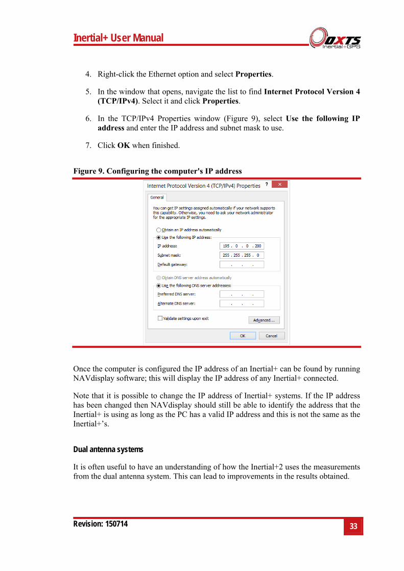
4. Right-click the Ethernet option and select Properties.
5. In the window that opens, navigate the list to find Internet Protocol Version 4 (TCP/IPv4). Select it and click Properties.
6. In the TCP/IPv4 Properties window (Figure 9), select Use the following IP address and enter the IP address and subnet mask to use.
7. Click OK when finished.
Figure 9. Configuring the computer's IP address
Once the computer is configured the IP address of an Inertial+ can be found by running NAVdisplay software; this will display the IP address of any Inertial+ connected.
Note that it is possible to change the IP address of Inertial+ systems. If the IP address has been changed then NAVdisplay should still be able to identify the address that the Inertial+ is using as long as the PC has a valid IP address and this is not the same as the Inertial+’s.
Dual antenna systems
It is often useful to have an understanding of how the Inertial+2 uses the measurements from the dual antenna system. This can lead to improvements in the results obtained.

34 Oxford Technical Solutions
1. To use the measurements properly the Inertial+2 needs to know the angle of the GNSS antennas compared to the angle of the Inertial+2. This cannot be measured accurately by users without specialised equipment; the Inertial+2 needs to measure this itself as part of the warm-up process.
2. The Inertial+2 will lock on to satellites, but it cannot estimate heading so it cannot start. Either motion or static initialisation can be used to initialize the Inertial+2
3. When the vehicle drives forward and reaches the initialisation speed, the Inertial+2 assumes that the heading and track are similar and initialises heading to track angle.
If the Inertial+2 is mounted in the vehicle with a large heading offset then the initial value of heading will be incorrect. This can also happen if the Inertial+2 is initialized in a turn. This can lead to problems later.
4. When the combined accuracy of heading plus the orientation accuracy figure for the secondary antenna is sufficiently accurate then the Inertial+2 will solve the RTK Integer problem using the inertial heading. There is no need for the Inertial+2 to solve the RTK Integer problem by searching.
If the antenna angle is offset from the Inertial+2 by a lot then the RTK Integer solution that is solved will be incorrect. For a 2 m antenna separation the Inertial+2 orientation and the secondary antenna orientation should be known to within 5°. For wider separations the secondary antenna orientation angle needs to be more accurate.
5. Once the RTK Integer solution is available, the Inertial+2 can start to use the dual antenna solution to improve heading. The level of correction that can be applied depends on how accurately the angle of the secondary antenna is known compared to the inertial sensors.
6. The Kalman filter tries to estimate the angle between the inertial sensors and the secondary antenna. The default value used in the configuration software (5°) is not accurate enough so that the Inertial+2 can improve the heading using this value. If you want the vehicle heading to 0.1°, but the angle of the two GNSS antennas is only known to 5°, then the measurements from the antenna are not going to be able to improve the heading of the vehicle.
Driving a normal warm-up, with stops, starts and turns, helps the Kalman filter improve the accuracy of the secondary antenna angle. The accuracy of this angle is available in NAVdisplay. On aircraft or marine vehicles some turns are needed to help the Kalman filter estimate the relative angle of the antennas compared to the Inertial+2.
Inertial+ User Manual
Revision: 150714 35
7. In the unlikely event that the RTK Integer solution is incorrect at the start then the Kalman filter can update the secondary antenna orientation incorrectly. If this happens then things start to go wrong. The Kalman filter becomes more convinced that it is correct, so it resolves faster, but it always solves incorrectly. Solving incorrectly makes the situation worse.
To avoid the Kalman filter from getting things wrong it is possible to drive a calibration run, then use the Improve configuration utility within NAVconfig (see page Error! Bookmark not defined. for more information). This tells the Kalman filter it has already estimated the angle of the secondary antenna in the past and it will be much less likely to get it wrong or change it. This step should only be done if the Inertial+2 is permanently mounted in a vehicle and the antennas are bolted on. Any movement of either the Inertial+2 or the antennas will upset the algorithms.
Multipath Effects on Dual Antenna Systems
Dual antenna systems are very susceptible to the errors caused by multipath. This can be from buildings, trees, roof-bars, etc. Multipath is where the signal from the satellite has a direct path and one or more reflected paths. Because the reflected paths are not the same length as the direct path, the GNSS receiver cannot track the satellite signal as accurately.
The dual antenna system in the Inertial+2 works by comparing the carrier-phase measurements at the two antennas. This tells the system the relative distance between the two antennas and which way they are pointing (the heading). For the heading to be accurate the GNSS receivers must measure the relative position to about 3 mm. The level of accuracy can only be achieved if there is little or no multipath.
In an ideal environment, with no surrounding building, trees, road signs or other reflective surfaces, the only multipath received is from the vehicle’s roof. The antennas supplied with the Inertial+2 are designed to minimise multipath from the vehicle’s roof when the roof is made of metal. For use on non-metallic roofs a different type of antenna is required.
When stationary the heading from the Inertial+2 will show some error, the size of the error depends on the multipath in the environment. Table 19 lists the error you can expect when stationary with a 1 m base-line.

36 Oxford Technical Solutions
Table 19. Typical heading error for when stationary in different environments
Environment Typical error (3σ
Complete open-sky 0.45° (0.3° 1σ
Near trees, buildings 1°
Next to trees, buildings 2°
Typical figures using a 1 m base-line. For accuracy specification of 0.15° RMS a 2 m separation is required. Using a 2 m base-line can halve the figures shown here.
Inertial+ User Manual
Revision: 150714 37
Inputs and outputs
This section describes the connectors and the signals on the Inertial+. All connections to the Inertial+ are marked on the front panel, shown in Figure 5 on page 26.
The system can output data on the serial port or over Ethernet. The standard serial output of the Inertial+ is a proprietary binary format, referred to as NCOM. OxTS offers C and C++ code that will interpret the packet. This can be used freely in users’ programs to interpret the output of the Inertial+. More information about NCOM can be found in the NCOM description manual.
It is also possible to output a standard NMEA string from the Inertial+ to mimic the output of standard GNSS receivers.
OxTS offers a service to tailor the serial output format to the customer’s specification. Contact Oxford Technical Solutions for details of this service.
Pin assignments
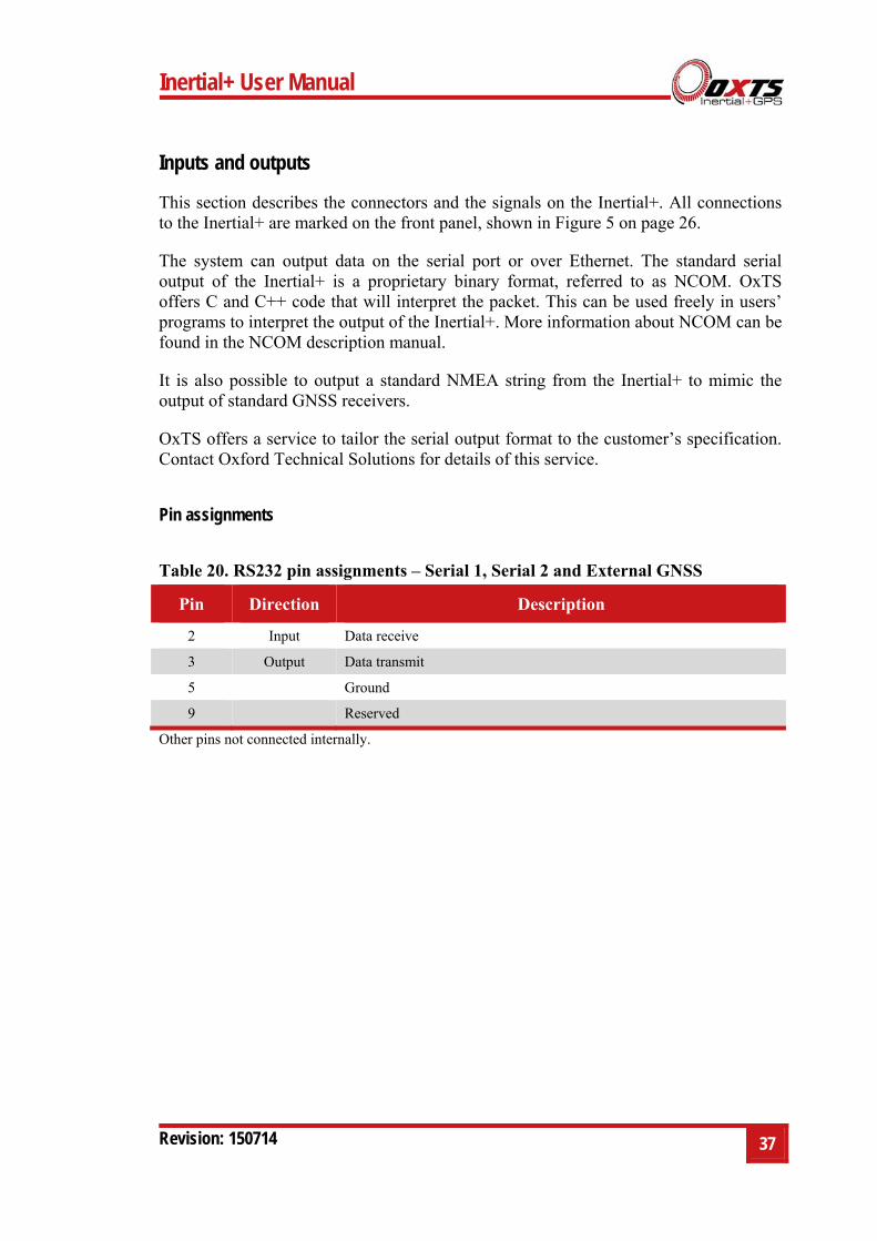
Table 20. RS232 pin assignments – Serial 1, Serial 2 and External GNSS
Pin Direction Description
2 Input Data receive
3 Output Data transmit
5 Ground
9 Reserved
Other pins not connected internally.
38 Oxford Technical Solutions
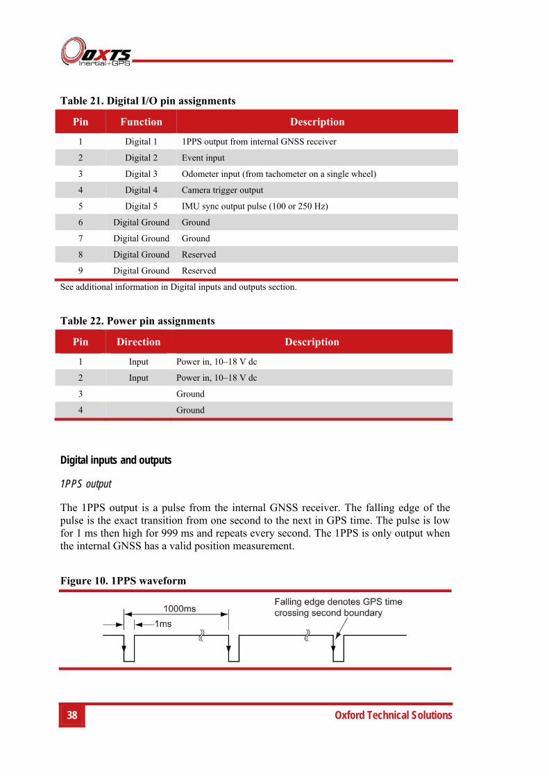
Table 21. Digital I/O pin assignments
Pin Function Description
1 Digital 1 1PPS output from internal GNSS receiver
2 Digital 2 Event input
3 Digital 3 Odometer input (from tachometer on a single wheel)
4 Digital 4 Camera trigger output
5 Digital 5 IMU sync output pulse (100 or 250 Hz)
6 Digital Ground Ground
7 Digital Ground Ground
8 Digital Ground Reserved
9 Digital Ground Reserved
See additional information in Digital inputs and outputs section.
Table 22. Power pin assignments
Pin Direction Description
1 Input Power in, 10–18 V dc
2 Input Power in, 10–18 V dc
3 Ground
4 Ground
Digital inputs and outputs
1PPS output
The 1PPS output is a pulse from the internal GNSS receiver. The falling edge of the pulse is the exact transition from one second to the next in GPS time. The pulse is low for 1 ms then high for 999 ms and repeats every second. The 1PPS is only output when the internal GNSS has a valid position measurement.
Figure 10. 1PPS waveform
Inertial+ User Manual
Revision: 150714 39
The output is a low-voltage CMOS output, with 0.8 V or less representing a low and 2.4 V or more representing a high. No more than 10 mA should be drawn from this output. Older models have no protection on this output (protection circuitry would disturb the accuracy of the timing). New models (2013 onwards) have limited protection.
Event input
The event input can be used to time events, like the shutter of a camera or a brake switch. The event input has a pull-up resistor so it can be used with a switch or as a CMOS input. A low-voltage requires less than 0.8 V on the input and a high voltage requires more than 2.4 V on the input. There is no protection on this input (protection circuitry would disturb the accuracy of the timing). Keep the input in the range of 0 V to 5 V.
By default the maximum event rate is 1 Hz for 100 Hz products and 4 Hz for 250 Hz products. This can be increased to 50 Hz by selecting one or both the Output on falling edge of trigger and Output on rising edge of trigger check boxes on the Ethernet Output window. This is accessed from the Options page in NAVconfig (see “Ethernet output” on page 62 of this manual).
Trigger information can be found in status message 24 (output over NCOM) for the triggers.
Odometer input
The odometer input accepts TTL pulses from an encoder on a single wheel. An encoder from a gearbox should not be used, and simulated TTL pulses (e.g. from a CAN bus) should not be used. The timing of the odometer input pulses is critical and nothing should cause any delay in the pulses.
The odometer input requires less than 0.8 V for a low pulse and more than 2.4 V for a high pulse. Limited protection is provided on this input, however the input voltage should not exceed 12 V.
The wheel that is used should not steer the vehicle. The Inertial+ will assume that this wheel travels straight.
Camera trigger output
The camera trigger output generates a pulse for a fixed distance travelled. The configuration software can change the number of metres travelled between pulses. The output has 0.8 V or less for a low and 2.4 V or more for a high. There is no protection on this output, no more than 10 mA should be used on this output.

40 Oxford Technical Solutions
IMU sync output pulse
The IMU (inertial measurement unit) sync output pulse is a 100 Hz or 250 Hz output pulse synchronised to the IMU sample time. The output has a duty cycle of approximately 50 % and the falling edge is synchronised to the sample file of the data from the IMU.
The IMU is already synchronised to GPS time so one of the pulses each second will line up with the 1PPS output. This allows other systems to sample based on the timing of the Inertial+.
Reverse polarity protection
The Inertial+ products have limited reverse polarity protection. Reversing the polarity on the power inputs for short periods of time is unlikely to damage the product.
Causing a short circuit through the Inertial+ will damage the product. A short-circuit will be created if the polarity is reversed and another connector has ground connected. In this condition the ground input of the power supply will be connected to the positive power supply; this causes a high current to flow through the circuits in the Inertial+ and it will damage several internal components.
Inertial+ User Manual
Revision: 150714 41
Configuring the Inertial+
To obtain the best results from your Inertial+ it will be necessary to configure it to suit the installation and application before using it for the first time.
The program NAVconfig can be used to do this. This section describes how to use NAVconfig and gives additional explanations on the meanings of some of the terms used.
It is only possible to change the Inertial+ configuration using Ethernet. It is necessary to have the Ethernet on your computer configured correctly in order to communicate with the Inertial+ and change the settings. See the section “Ethernet configuration” on page 32 for more information.
Overview
In order to give the best possible performance, the Inertial+ needs to know the following things:
The type of GNSS receiver fitted.
The orientation that the Inertial+ is mounted at in the vehicle.
The position of the external GNSS antenna compared to the Inertial+.
The position of the rear wheels (or non-steering wheels) compared to the Inertial+.
The position of the odometer compared to the Inertial+.
The orientation of the dual antenna system (if applicable).
The Inertial+ can work out many of these parameters by itself, but this takes time. Measuring the parameters yourself and configuring the Inertial+ reduces the time taken to achieve full specification.
If the Inertial+ has been running for some time, it will have improved the measurements. It is possible to read these improved measurements into NAVconfig, commit them to the Inertial+, then use them next time you start the system. If you move the Inertial+ from one vehicle to another it is essential you return to the default configuration rather than using parameters that have been tuned for a different vehicle.
Selecting the operating language
The NAVconfig software can operate in several languages. To change language, select the language from the drop down menu at the bottom of the page. The language is “hot-swappable” making it easy and fast to switch between languages.
42 Oxford Technical Solutions
The software will use the regional settings of the computer to choose whether numbers are represented in the English or European format (dot or comma for the decimal separator). The selected language does not change the format used for numbers.
Navigating through NAVconfig
NAVconfig provides a ten-step process to make configuring your product as easy as possible. After completing each step, click the Next button at the bottom of the window to proceed to the next step. The Back button can be used to return to the previous step at any time. Clicking Cancel will bring up a warning asking to confirm you want to close the wizard and lose any changes you have not saved.
To quickly move between any of the steps, click on the step name in the sidebar to instantly jump to that page.
Measurements are always displayed in metric units in NAVconfig. However, when entering measurements alternate units can be used as long as they are specified, e.g. 10″ or 10 in. NAVconfig will then convert and display these in metric units.
Product selection
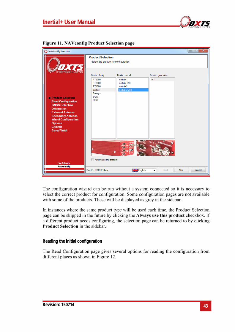
The first page of the NAVconfig configuration wizard lets you select the type of product for configuration, see Figure 11.
Inertial+ User Manual
Revision: 150714 43
Figure 11. NAVconfig Product Selection page
The configuration wizard can be run without a system connected so it is necessary to select the correct product for configuration. Some configuration pages are not available with some of the products. These will be displayed as grey in the sidebar.
In instances where the same product type will be used each time, the Product Selection page can be skipped in the future by clicking the Always use this product checkbox. If a different product needs configuring, the selection page can be returned to by clicking Product Selection in the sidebar.
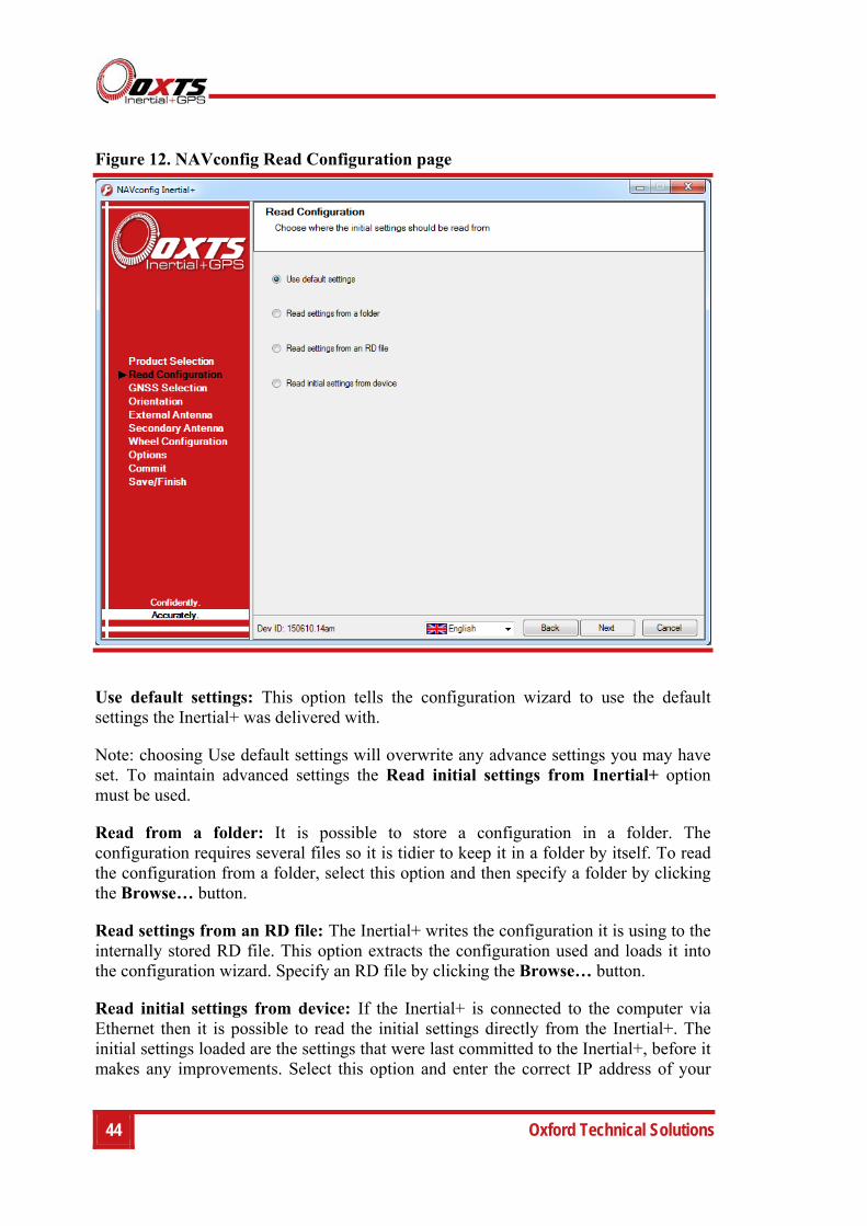
Reading the initial configuration
The Read Configuration page gives several options for reading the configuration from different places as shown in Figure 12.
44 Oxford Technical Solutions
Figure 12. NAVconfig Read Configuration page
Use default settings: This option tells the configuration wizard to use the default settings the Inertial+ was delivered with.
Note: choosing Use default settings will overwrite any advance settings you may have set. To maintain advanced settings the Read initial settings from Inertial+ option must be used.
Read from a folder: It is possible to store a configuration in a folder. The configuration requires several files so it is tidier to keep it in a folder by itself. To read the configuration from a folder, select this option and then specify a folder by clicking the Browse… button.
Read settings from an RD file: The Inertial+ writes the configuration it is using to the internally stored RD file. This option extracts the configuration used and loads it into the configuration wizard. Specify an RD file by clicking the Browse… button.
Read initial settings from device: If the Inertial+ is connected to the computer via Ethernet then it is possible to read the initial settings directly from the Inertial+. The initial settings loaded are the settings that were last committed to the Inertial+, before it makes any improvements. Select this option and enter the correct IP address of your
Inertial+ User Manual
Revision: 150714 45
Inertial+ or select it from the drop-down list. The list will show all systems that are connected to the network, so if more than one system is connected ensure you select the correct system. Note: the list will not function correctly if Enginuity or other software is using the Inertial+ UDP port unless the OxTS UDP Server is running.
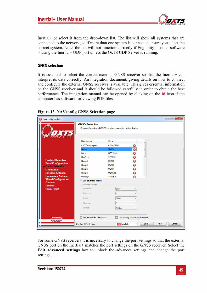
GNSS selection
It is essential to select the correct external GNSS receiver so that the Inertial+ can interpret its data correctly. An integration document, giving details on how to connect and configure the external GNSS receiver is available. This gives essential information on the GNSS receiver and it should be followed carefully in order to obtain the best performance. The integration manual can be opened by clicking on the icon if the computer has software for viewing PDF files.
Figure 13. NAVconfig GNSS Selection page
For some GNSS receivers it is necessary to change the port settings so that the external GNSS port on the Inertial+ matches the port settings on the GNSS receiver. Select the Edit advanced settings box to unlock the advances settings and change the port settings.
46 Oxford Technical Solutions
The advanced settings can also be used to change the format of the receiver being used. For example, if a Novatel OEMV receiver is being used with NMEA then OEMV should be selected from the list and NMEA should be selected from the Format dropdown list in advanced settings. Mixing receivers and formats is not recommended unless directed by OxTS.
The Inertial+ has internal GNSS receivers that are used to obtain a GPS time-stamp for synchronising measurements, or for computing a heading solution in dual antenna systems. The internal GNSS receiver is a low-cost receiver and it not capable for giving good position measurements. If you wish to use the internal receivers for position measurements instead of an external receiver for debugging or testing the Inertial+, click the Use internal GNSS receiver checkbox. This will disable the GNSS receiver list and the Inertial+ will ignore any external GNSS measurements even if one is connected.
The Use heading from external receiver option has no effect on devices that do not have an external heading feature code active on the system. If this feature code is active, then selecting the Use heading from external receiver box allows both Inertial+ and Inertial+2 to take advantage of heading and pitch information being sent from external dual-antenna receivers. Currently, heading information is supported over three interfaces; Trimble GSOF, NovAtel binary and NMEA (PASHR).
Note: when the Use heading from external receiver option is selected, the measurements entered on NAVconfig’s Secondary Antenna page relate to the position of the secondary external receiver.
Except for NMEA input, only RTK-Integer attitude status updates are used by the system. Advanced options can be used to force the accuracy model to ignore the reported accuracy and accept a user-specified level. Contact OxTS support for information about this.
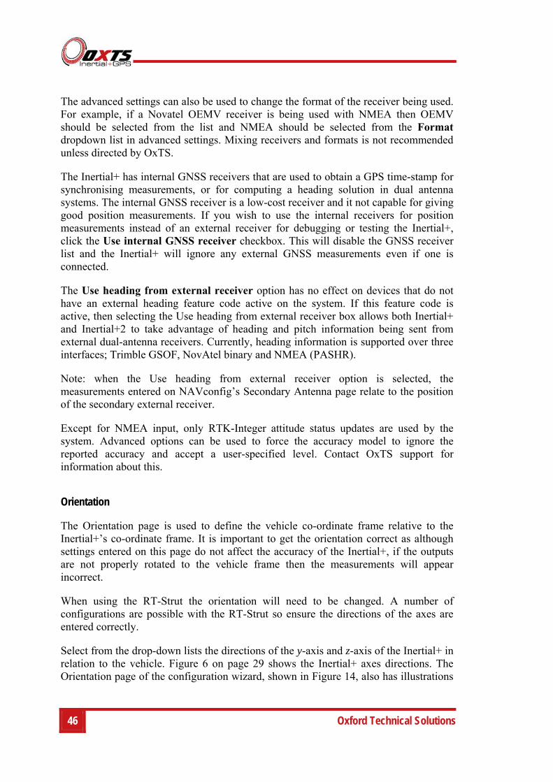
Orientation
The Orientation page is used to define the vehicle co-ordinate frame relative to the Inertial+’s co-ordinate frame. It is important to get the orientation correct as although settings entered on this page do not affect the accuracy of the Inertial+, if the outputs are not properly rotated to the vehicle frame then the measurements will appear incorrect.
When using the RT-Strut the orientation will need to be changed. A number of configurations are possible with the RT-Strut so ensure the directions of the axes are entered correctly.
Select from the drop-down lists the directions of the y-axis and z-axis of the Inertial+ in relation to the vehicle. Figure 6 on page 29 shows the Inertial+ axes directions. The Orientation page of the configuration wizard, shown in Figure 14, also has illustrations
Inertial+ User Manual
Revision: 150714 47
to visualise the orientation of the Inertial+ in a vehicle based on the settings input. The greyed out advanced settings will change to show the three rotations associated with orientation input
Figure 14. NAVconfig Orientation page
For correct initialisation it is necessary to get the heading orientation correct. The Inertial+ gets its initial heading by assuming that the vehicle is travelling forwards in a straight line. If the definition of the vehicle’s x-axis (forward direction) is incorrect in the Inertial+ then it will not initialise correctly when the vehicle drives forwards.
To make small adjustments, select the Edit advanced settings box to unlock the rotations for editing. This allows any slip angle, pitch or roll offsets to be zeroed.
Get improved settings
Also included on the Orientation page is the ability to read the configuration settings from a warmed-up system. While the Inertial+ is running, it tries to improve some of its configured parameters. This option is useful if a calibration run has been done and the Kalman filter’s values are known to be good.
48 Oxford Technical Solutions
In particular the Inertial+ will try to improve the external GNSS antenna position, the orientation of the dual antennas, the yaw orientation of the Inertial+ in the vehicle and the wheel speed calibration values. For applications where the Inertial+ is installed permanently in the vehicle it can be beneficial to use the values that the Inertial+ has learned next time you use the Inertial+. It can make the results more consistent. However, this feature should not be used if there is a risk the Inertial+ will rotate in the vehicle or that the GNSS antennas can move—even by a few millimetres.
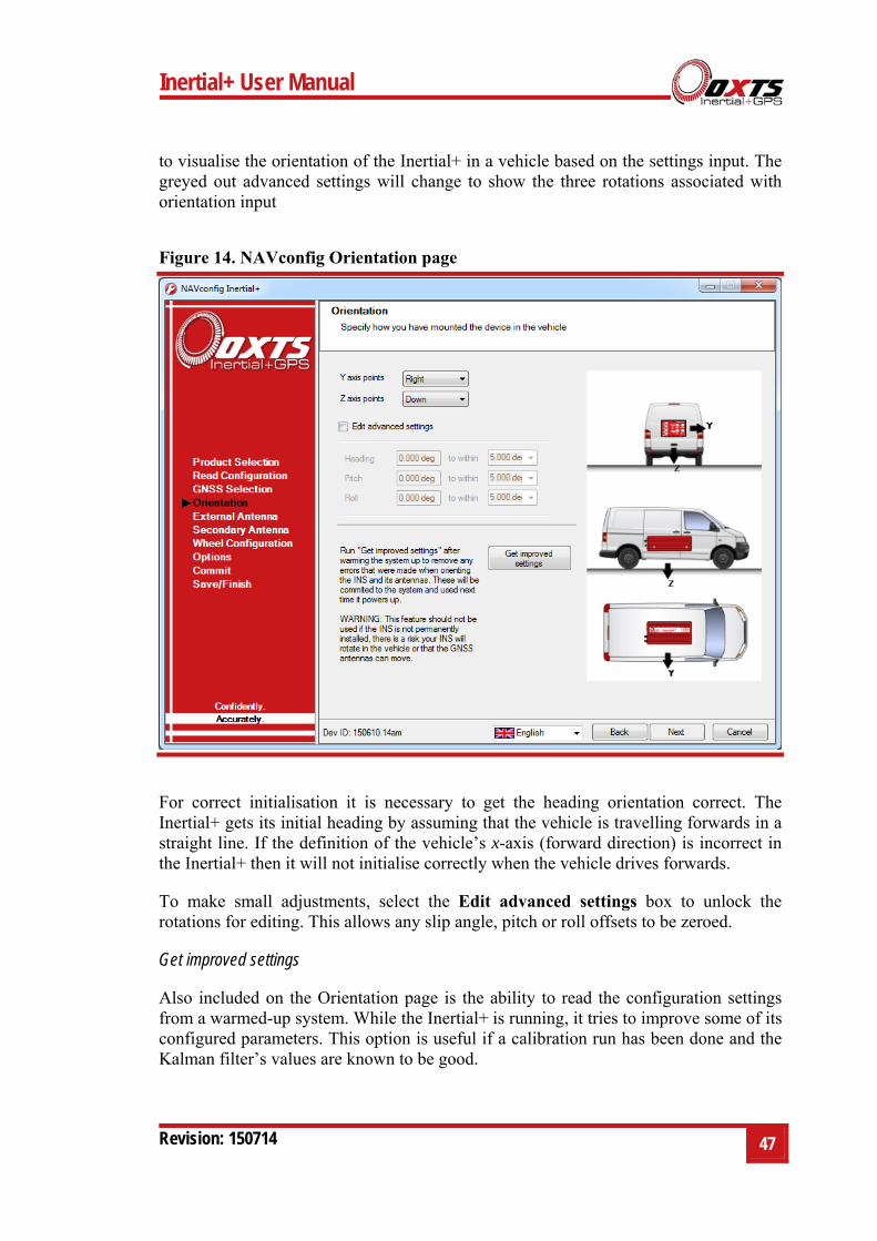
To read the improved values from the Inertial+, click the … button on the Orientation page to open the Get settings from Inertial+ window, as shown in Figure 15.
Figure 15. NAVconfig source selection page for improved configuration
Click the drop-down list and choose which source to read the configuration from. The two options are:
Read configuration from file. If an NCOM file has been saved to disk, or processed using the post-process utility then this file can be read and the settings extracted from it. Use this setting if you have an NCOM file. Click Browse… and select the NCOM file you wish to read the configuration from. Do not use an NCOM file that has been combined from forward and backwards processing of the inertial data.
Read configuration from Ethernet. This will get the information that the Inertial+ is currently using and apply it next time the Inertial+ starts. Use this setting if the Inertial+ is running, has initialised and has warmed up. Select the correct IP address of the Inertial+ to read the configuration from in the drop-down list. Note: the list will not function correctly if Enginuity or other software is using the Inertial+ UDP port unless the OxTS UDP Server is running.
Inertial+ User Manual
Revision: 150714 49
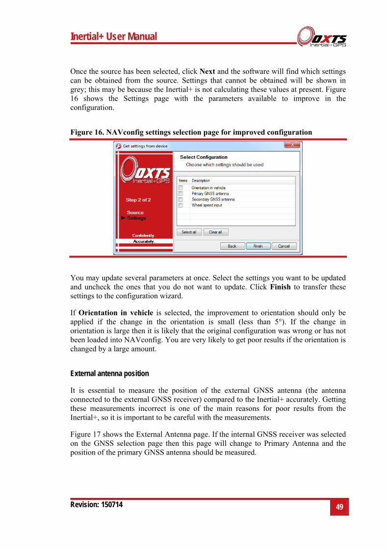
Once the source has been selected, click Next and the software will find which settings can be obtained from the source. Settings that cannot be obtained will be shown in grey; this may be because the Inertial+ is not calculating these values at present. Figure 16 shows the Settings page with the parameters available to improve in the configuration.
Figure 16. NAVconfig settings selection page for improved configuration
You may update several parameters at once. Select the settings you want to be updated and uncheck the ones that you do not want to update. Click Finish to transfer these settings to the configuration wizard.
If Orientation in vehicle is selected, the improvement to orientation should only be applied if the change in the orientation is small (less than 5°). If the change in orientation is large then it is likely that the original configuration was wrong or has not been loaded into NAVconfig. You are very likely to get poor results if the orientation is changed by a large amount.
External antenna position
It is essential to measure the position of the external GNSS antenna (the antenna connected to the external GNSS receiver) compared to the Inertial+ accurately. Getting these measurements incorrect is one of the main reasons for poor results from the Inertial+, so it is important to be careful with the measurements.
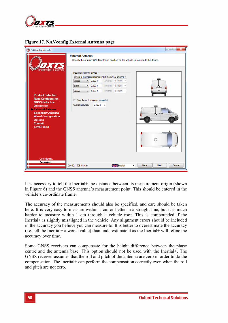
Figure 17 shows the External Antenna page. If the internal GNSS receiver was selected on the GNSS selection page then this page will change to Primary Antenna and the position of the primary GNSS antenna should be measured.
50 Oxford Technical Solutions
Figure 17. NAVconfig External Antenna page
It is necessary to tell the Inertial+ the distance between its measurement origin (shown in Figure 6) and the GNSS antenna’s measurement point. This should be entered in the vehicle’s co-ordinate frame.
The accuracy of the measurements should also be specified, and care should be taken here. It is very easy to measure within 1 cm or better in a straight line, but it is much harder to measure within 1 cm through a vehicle roof. This is compounded if the Inertial+ is slightly misaligned in the vehicle. Any alignment errors should be included in the accuracy you believe you can measure to. It is better to overestimate the accuracy (i.e. tell the Inertial+ a worse value) than underestimate it as the Inertial+ will refine the accuracy over time.
Some GNSS receivers can compensate for the height difference between the phase centre and the antenna base. This option should not be used with the Inertial+. The GNSS receiver assumes that the roll and pitch of the antenna are zero in order to do the compensation. The Inertial+ can perform the compensation correctly even when the roll and pitch are not zero.
Inertial+ User Manual
Revision: 150714 51
Secondary antenna position
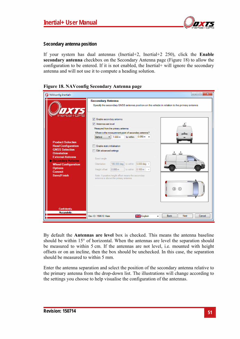
If your system has dual antennas (Inertial+2, Inertial+2 250), click the Enable secondary antenna checkbox on the Secondary Antenna page (Figure 18) to allow the configuration to be entered. If it is not enabled, the Inertial+ will ignore the secondary antenna and will not use it to compute a heading solution.
Figure 18. NAVconfig Secondary Antenna page
By default the Antennas are level box is checked. This means the antenna baseline should be within 15° of horizontal. When the antennas are level the separation should be measured to within 5 cm. If the antennas are not level, i.e. mounted with height offsets or on an incline, then the box should be unchecked. In this case, the separation should be measured to within 5 mm.
Enter the antenna separation and select the position of the secondary antenna relative to the primary antenna from the drop-down list. The illustrations will change according to the settings you choose to help visualise the configuration of the antennas.
52 Oxford Technical Solutions
A wider separation will increase the dual antenna heading solution accuracy. The maximum recommended separation in 5 m, giving an accuracy of up to 0.06° in both static and dynamic conditions.
If the antennas are mounted at significantly different heights, or if the mounting angle is not directly along a vehicle axis (forward or right), then click the Use advanced settings checkbox to enable advanced settings and specify the orientation and height offset.
Getting the angle wrong by more than 3° can lead the Inertial+ to lock on to the wrong heading solution. The performance will degrade or be erratic if this happens. If the angle between the antennas cannot be estimated within a 3° tolerance then contact OxTS support for techniques for identifying the angle of the antennas.
The Enable static initialisation option is useful for slow moving vehicles or when dynamic initialisation may be difficult. Static initialisation is 99% reliable in open sky, but the reliability decreases in environments with high multipath. Static initialisation is also faster when the antenna separation is smaller and the Antennas are level checkbox is ticked.
The static initialisation algorithms degrade rapidly in non-ideal conditions. They should only be used in open sky environments. Using a shorter separation or using the pitch constraint can improve the accuracy in non-ideal conditions.
Wheel configuration
Thw Wheel configuration feature uses characteristics of land vehicle motion to improve heading performance and reduce drift when GNSS is not available. The wheel configuration can only be used on land vehicles with non-steered wheels. Aircraft and marine vehicles cannot use this option. It is also not suitable for land vehicles with no fixed wheels. The vertical settings should not be used on vehicles that can perform wheelies.
The Inertial+ uses the position of the non-steered wheels to reduce the lateral drift when GNSS is not available and to improve the heading accuracy. When combined with an odometer input the drift of the Inertial+ when GNSS is not available is drastically reduced.
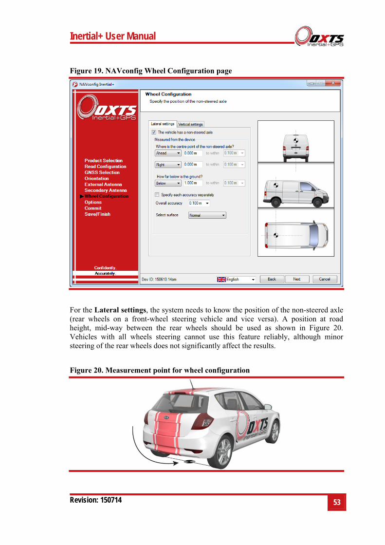
Figure 19 shows the Wheel Configuration page.
Inertial+ User Manual
Revision: 150714 53
Figure 19. NAVconfig Wheel Configuration page
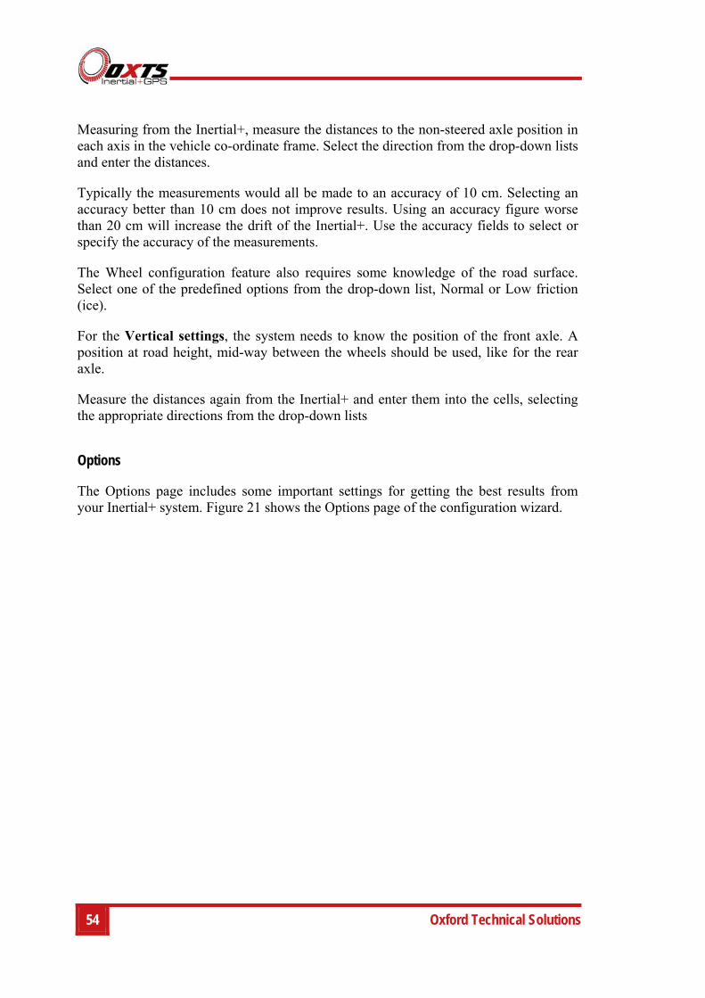
For the Lateral settings, the system needs to know the position of the non-steered axle (rear wheels on a front-wheel steering vehicle and vice versa). A position at road height, mid-way between the rear wheels should be used as shown in Figure 20. Vehicles with all wheels steering cannot use this feature reliably, although minor steering of the rear wheels does not significantly affect the results.
Figure 20. Measurement point for wheel configuration
54 Oxford Technical Solutions
Measuring from the Inertial+, measure the distances to the non-steered axle position in each axis in the vehicle co-ordinate frame. Select the direction from the drop-down lists and enter the distances.
Typically the measurements would all be made to an accuracy of 10 cm. Selecting an accuracy better than 10 cm does not improve results. Using an accuracy figure worse than 20 cm will increase the drift of the Inertial+. Use the accuracy fields to select or specify the accuracy of the measurements.
The Wheel configuration feature also requires some knowledge of the road surface. Select one of the predefined options from the drop-down list, Normal or Low friction (ice).
For the Vertical settings, the system needs to know the position of the front axle. A position at road height, mid-way between the wheels should be used, like for the rear axle.
Measure the distances again from the Inertial+ and enter them into the cells, selecting the appropriate directions from the drop-down lists
Options
The Options page includes some important settings for getting the best results from your Inertial+ system. Figure 21 shows the Options page of the configuration wizard.

Inertial+ User Manual
Revision: 150714 55
Figure 21. NAVconfig Options page
Vehicle starts
Adjustment: select a predefined value from the drop-down list.
If you know the vehicle will be level when starting (to within about 5°) select Level. This saves about 40 s during the initialisation process since the Inertial+ does not have to take the time to compute an initial roll and an initial pitch. In high vibration environments Not Level may not work and so the Inertial+ can only start if the vehicle is level and the Level option has been specified.
Initialisation speed
Adjustment: select a predefined value from the drop-down list or type in a value.
If static initialisation has not been enabled, the Inertial+ will need to be initialised by driving forwards in a straight line to initialise the heading to the track angle. The initialisation speed is the speed at which the vehicle must travel to activate the initialisation.
56 Oxford Technical Solutions
The default initialisation speed for the Inertial+ is 5 m/s. However, some slow vehicles cannot achieve this speed. For these vehicles adjust the initialisation speed to a different value.
If a speed less than 5 m/s is selected then care should be taken to make sure that the Inertial+ is travelling straight when it initialises. The accuracy of some GNSS receivers is not good enough to initialize at very low speeds.
Displace output
Adjustment: click … button to open properties window.
The Inertial+ can displace or move its outputs to another location in the vehicle. This simulates the Inertial+ being mounted at the new location, rather than at its actual location. This function displaces all of the outputs (position, velocity, acceleration) to this new location.
To enable output displacement, click the checkbox in the properties window and enter the offsets to the new location in the vehicle. The offsets are measured from the Inertial+ in the vehicle co-ordinate frame. Select the directions from the drop-down lists.
Note that the noise in the acceleration outputs will be much higher when output displacement is used. Typical installations in moving vehicles have angular vibrations of about 2 rads/s²; this equates to 2 m/s² of additional vibration of a 1 m output displacement. It will be necessary to filter the data if output displacement is used.
Camera trigger
The Inertial+ can generate a regular pulse based on distance; for example, one pulse every 10 m of travel. This can be used to trigger a camera so that a picture can be taken on a regular basis.
Enter the distance between pulses or leave disabled (default).
Heading lock
Adjustment: select a predefined value from the drop-down list.
The heading of the single antenna Inertial+ can drift when it remains stationary for long periods of time. To solve this, the Inertial+ includes an option to lock the heading to a fixed value when stationary. This option cannot be used if the vehicle can turn on the spot (i.e. on a boat). With heading lock enabled the Inertial+ can remain stationary for indefinite periods of time without any problems.
There are four settings to choose from. Disabled should be selected if the vehicle can turn on the spot. The default setting Normal is best for most applications as it is least
Inertial+ User Manual
Revision: 150714 57
likely to cause problems in the Kalman filter. Tight and Very tight are better when trying to reduce position drift in poor GNSS environments and traffic jams.
Table 23 gives a more detailed description on each of the heading lock options.
Table 23. NAVconfig heading lock options
Heading lock Description
Normal This option assumes that the heading of the vehicle does not change by more than 2° while the vehicle is stationary. The heading accuracy recovers quickly when the vehicle moves.
Tight This option assumes that the heading of the vehicle does not change by more than 0.5° while the vehicle is stationary. The recovery is fast if the heading of the vehicle does not change but will be slow if the vehicle turns before it moves.
Very tight The option assumes that the heading of the vehicle does not change by more than 0.3° while the vehicle is stationary. The recovery is fast if the heading of the vehicle does not change but will be slow if the vehicle turns before it moves. This option can cause problems during the warm-up period if the vehicle remains stationary for a long time and then drives suddenly.
Note: The heading of most vehicles does change if the steering wheel is turned while the vehicle is stationary. Junctions and pulling out of parking spaces are common places where drivers turn the steering wheel while not moving.
Output lock
Adjustment: select a predefined value from the drop-down list.
The output of the Inertial+ will continue to change even when the vehicle is stationary. For some video systems this leads to ambiguous results. The position and orientation can be “locked” by the Inertial+ automatically when the vehicle becomes stationary.
While the outputs are locked, the Kalman filter continues to run and accumulate errors. When the vehicle moves, the Kalman filter will quickly return to the new solution. The drift rate can be controlled using the Output smoothing option.
Output smoothing
Adjustment: click … button to open properties window.
When the Kalman filter in the Inertial+ determines that there is some error to correct, this error is applied smoothly rather than as a jump. The output smoothing controls how fast the correction is applied to the outputs.
Figure 22 shows the Output smoothing window. Click the checkbox to enable output smoothing and unlock the properties for editing.
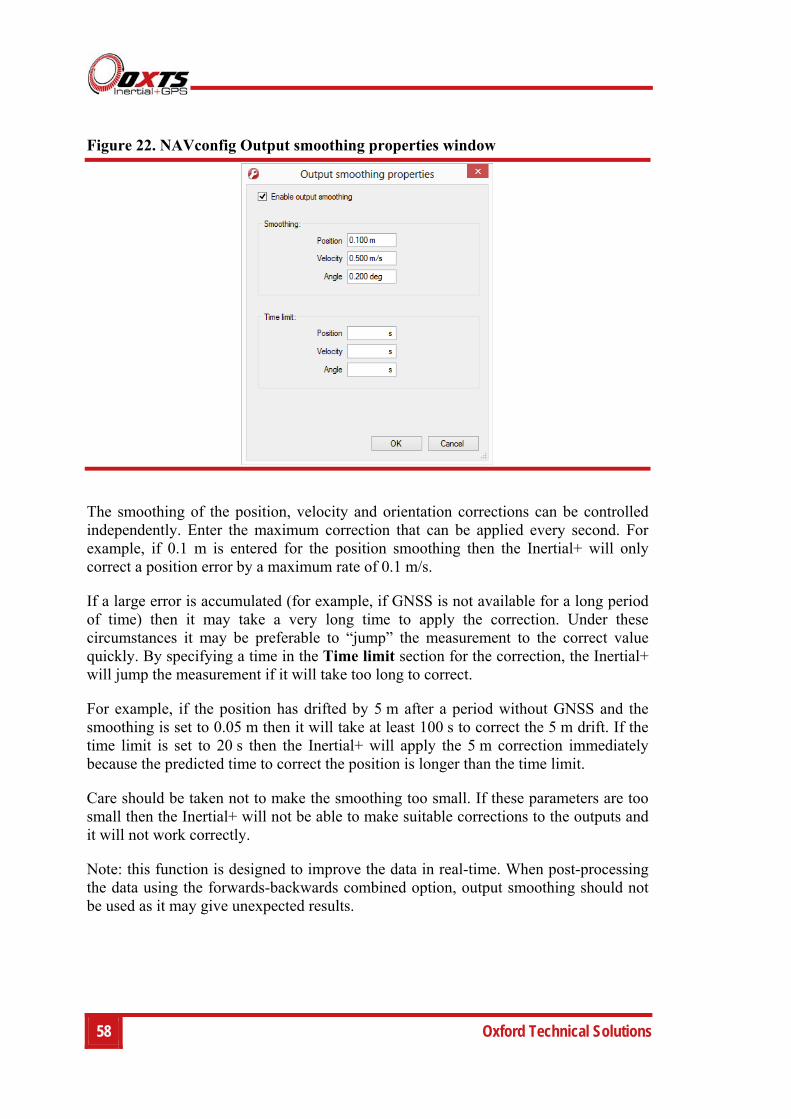
58 Oxford Technical Solutions
Figure 22. NAVconfig Output smoothing properties window
The smoothing of the position, velocity and orientation corrections can be controlled independently. Enter the maximum correction that can be applied every second. For example, if 0.1 m is entered for the position smoothing then the Inertial+ will only correct a position error by a maximum rate of 0.1 m/s.
If a large error is accumulated (for example, if GNSS is not available for a long period of time) then it may take a very long time to apply the correction. Under these circumstances it may be preferable to “jump” the measurement to the correct value quickly. By specifying a time in the Time limit section for the correction, the Inertial+ will jump the measurement if it will take too long to correct.
For example, if the position has drifted by 5 m after a period without GNSS and the smoothing is set to 0.05 m then it will take at least 100 s to correct the 5 m drift. If the time limit is set to 20 s then the Inertial+ will apply the 5 m correction immediately because the predicted time to correct the position is longer than the time limit.
Care should be taken not to make the smoothing too small. If these parameters are too small then the Inertial+ will not be able to make suitable corrections to the outputs and it will not work correctly.
Note: this function is designed to improve the data in real-time. When post-processing the data using the forwards-backwards combined option, output smoothing should not be used as it may give unexpected results.
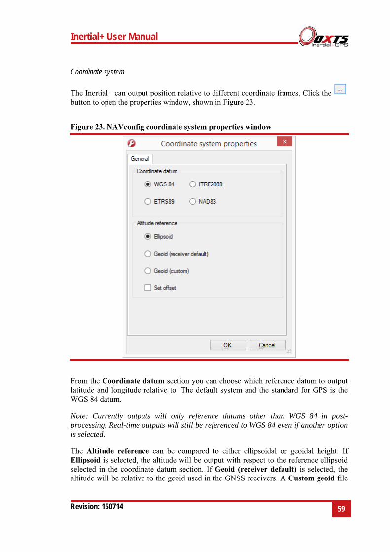
Inertial+ User Manual
Revision: 150714 59
Coordinate system
The Inertial+ can output position relative to different coordinate frames. Click the button to open the properties window, shown in Figure 23.
Figure 23. NAVconfig coordinate system properties window
From the Coordinate datum section you can choose which reference datum to output latitude and longitude relative to. The default system and the standard for GPS is the WGS 84 datum.
Note: Currently outputs will only reference datums other than WGS 84 in post-processing. Real-time outputs will still be referenced to WGS 84 even if another option is selected.
The Altitude reference can be compared to either ellipsoidal or geoidal height. If Ellipsoid is selected, the altitude will be output with respect to the reference ellipsoid selected in the coordinate datum section. If Geoid (receiver default) is selected, the altitude will be relative to the geoid used in the GNSS receivers. A Custom geoid file
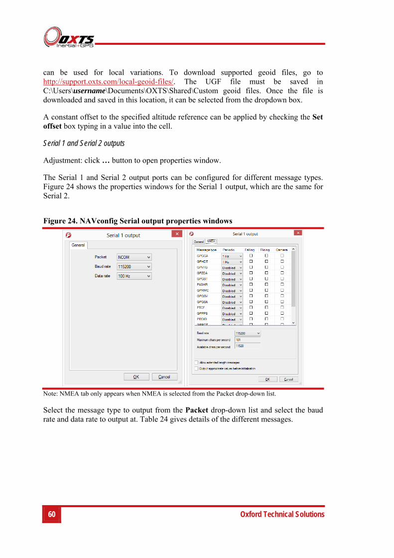
60 Oxford Technical Solutions
can be used for local variations. To download supported geoid files, go to http://support.oxts.com/local-geoid-files/. The UGF file must be saved in C:\Users\username\Documents\OXTS\Shared\Custom geoid files. Once the file is downloaded and saved in this location, it can be selected from the dropdown box.
A constant offset to the specified altitude reference can be applied by checking the Set offset box typing in a value into the cell.
Serial 1 and Serial 2 outputs
Adjustment: click … button to open properties window.
The Serial 1 and Serial 2 output ports can be configured for different message types. Figure 24 shows the properties windows for the Serial 1 output, which are the same for Serial 2.
Figure 24. NAVconfig Serial output properties windows
Note: NMEA tab only appears when NMEA is selected from the Packet drop-down list.
Select the message type to output from the Packet drop-down list and select the baud rate and data rate to output at. Table 24 gives details of the different messages.
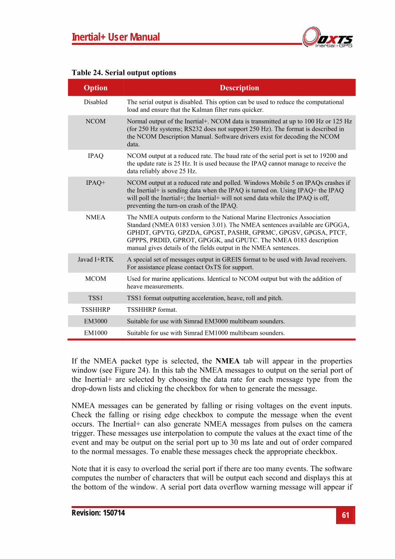
Inertial+ User Manual
Revision: 150714 61
Table 24. Serial output options
Option Description
Disabled The serial output is disabled. This option can be used to reduce the computational load and ensure that the Kalman filter runs quicker.
NCOM Normal output of the Inertial+. NCOM data is transmitted at up to 100 Hz or 125 Hz (for 250 Hz systems; RS232 does not support 250 Hz). The format is described in the NCOM Description Manual. Software drivers exist for decoding the NCOM data.
IPAQ NCOM output at a reduced rate. The baud rate of the serial port is set to 19200 and the update rate is 25 Hz. It is used because the IPAQ cannot manage to receive the data reliably above 25 Hz.
IPAQ+ NCOM output at a reduced rate and polled. Windows Mobile 5 on IPAQs crashes if the Inertial+ is sending data when the IPAQ is turned on. Using IPAQ+ the IPAQ will poll the Inertial+; the Inertial+ will not send data while the IPAQ is off, preventing the turn-on crash of the IPAQ.
NMEA The NMEA outputs conform to the National Marine Electronics Association Standard (NMEA 0183 version 3.01). The NMEA sentences available are GPGGA, GPHDT, GPVTG, GPZDA, GPGST, PASHR, GPRMC, GPGSV, GPGSA, PTCF, GPPPS, PRDID, GPROT, GPGGK, and GPUTC. The NMEA 0183 description manual gives details of the fields output in the NMEA sentences.
Javad I+RTK A special set of messages output in GREIS format to be used with Javad receivers. For assistance please contact OxTS for support.
MCOM Used for marine applications. Identical to NCOM output but with the addition of heave measurements.
TSS1 TSS1 format outputting acceleration, heave, roll and pitch.
TSSHHRP TSSHHRP format.
EM3000 Suitable for use with Simrad EM3000 multibeam sounders.
EM1000 Suitable for use with Simrad EM1000 multibeam sounders.
If the NMEA packet type is selected, the NMEA tab will appear in the properties window (see Figure 24). In this tab the NMEA messages to output on the serial port of the Inertial+ are selected by choosing the data rate for each message type from the drop-down lists and clicking the checkbox for when to generate the message.
NMEA messages can be generated by falling or rising voltages on the event inputs. Check the falling or rising edge checkbox to compute the message when the event occurs. The Inertial+ can also generate NMEA messages from pulses on the camera trigger. These messages use interpolation to compute the values at the exact time of the event and may be output on the serial port up to 30 ms late and out of order compared to the normal messages. To enable these messages check the appropriate checkbox.
Note that it is easy to overload the serial port if there are too many events. The software computes the number of characters that will be output each second and displays this at the bottom of the window. A serial port data overflow warning message will appear if
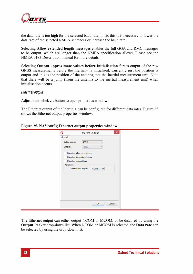
62 Oxford Technical Solutions
the data rate is too high for the selected baud rate; to fix this it is necessary to lower the data rate of the selected NMEA sentences or increase the baud rate.
Selecting Allow extended length messages enables the full GGA and RMC messages to be output, which are longer than the NMEA specification allows. Please see the NMEA 0183 Description manual for more details.
Selecting Output approximate values before initialisation forces output of the raw GNSS measurements before the Inertial+ is initialised. Currently just the position is output and this is the position of the antenna, not the inertial measurement unit. Note that there will be a jump (from the antenna to the inertial measurement unit) when initialisation occurs.
Ethernet output
Adjustment: click … button to open properties window.
The Ethernet output of the Inertial+ can be configured for different data rates. Figure 25 shows the Ethernet output properties window.
Figure 25. NAVconfig Ethernet output properties window
The Ethernet output can either output NCOM or MCOM, or be disabled by using the Output Packet drop-down list. When NCOM or MCOM is selected, the Data rate can be selected by using the drop-down list.
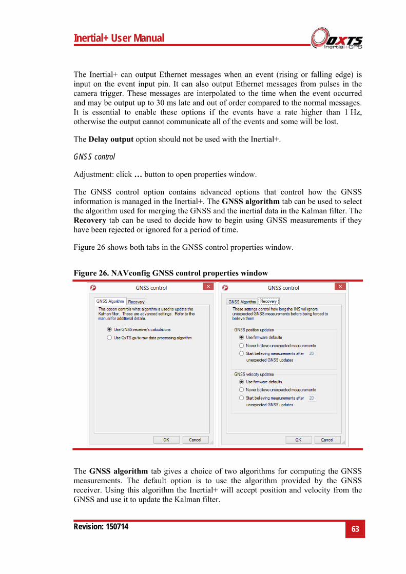
Inertial+ User Manual
Revision: 150714 63
The Inertial+ can output Ethernet messages when an event (rising or falling edge) is input on the event input pin. It can also output Ethernet messages from pulses in the camera trigger. These messages are interpolated to the time when the event occurred and may be output up to 30 ms late and out of order compared to the normal messages. It is essential to enable these options if the events have a rate higher than 1 Hz, otherwise the output cannot communicate all of the events and some will be lost.
The Delay output option should not be used with the Inertial+.
GNSS control
Adjustment: click … button to open properties window.
The GNSS control option contains advanced options that control how the GNSS information is managed in the Inertial+. The GNSS algorithm tab can be used to select the algorithm used for merging the GNSS and the inertial data in the Kalman filter. The Recovery tab can be used to decide how to begin using GNSS measurements if they have been rejected or ignored for a period of time.
Figure 26 shows both tabs in the GNSS control properties window.
Figure 26. NAVconfig GNSS control properties window
The GNSS algorithm tab gives a choice of two algorithms for computing the GNSS measurements. The default option is to use the algorithm provided by the GNSS receiver. Using this algorithm the Inertial+ will accept position and velocity from the GNSS and use it to update the Kalman filter.
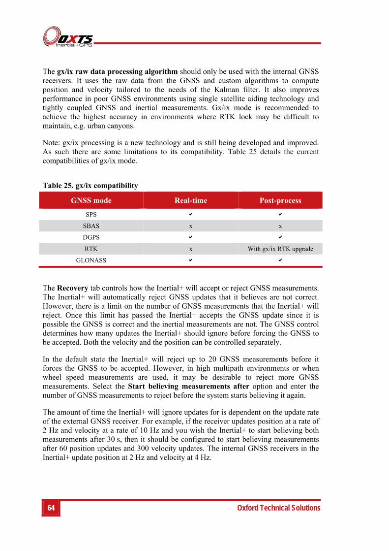
64 Oxford Technical Solutions
The gx/ix raw data processing algorithm should only be used with the internal GNSS receivers. It uses the raw data from the GNSS and custom algorithms to compute position and velocity tailored to the needs of the Kalman filter. It also improves performance in poor GNSS environments using single satellite aiding technology and tightly coupled GNSS and inertial measurements. Gx/ix mode is recommended to achieve the highest accuracy in environments where RTK lock may be difficult to maintain, e.g. urban canyons.
Note: gx/ix processing is a new technology and is still being developed and improved. As such there are some limitations to its compatibility. Table 25 details the current compatibilities of gx/ix mode.
Table 25. gx/ix compatibility
GNSS mode Real-time Post-process
SPS
SBAS x x
DGPS
RTK x With gx/ix RTK upgrade
GLONASS
The Recovery tab controls how the Inertial+ will accept or reject GNSS measurements. The Inertial+ will automatically reject GNSS updates that it believes are not correct. However, there is a limit on the number of GNSS measurements that the Inertial+ will reject. Once this limit has passed the Inertial+ accepts the GNSS update since it is possible the GNSS is correct and the inertial measurements are not. The GNSS control determines how many updates the Inertial+ should ignore before forcing the GNSS to be accepted. Both the velocity and the position can be controlled separately.
In the default state the Inertial+ will reject up to 20 GNSS measurements before it forces the GNSS to be accepted. However, in high multipath environments or when wheel speed measurements are used, it may be desirable to reject more GNSS measurements. Select the Start believing measurements after option and enter the number of GNSS measurements to reject before the system starts believing it again.
The amount of time the Inertial+ will ignore updates for is dependent on the update rate of the external GNSS receiver. For example, if the receiver updates position at a rate of 2 Hz and velocity at a rate of 10 Hz and you wish the Inertial+ to start believing both measurements after 30 s, then it should be configured to start believing measurements after 60 position updates and 300 velocity updates. The internal GNSS receivers in the Inertial+ update position at 2 Hz and velocity at 4 Hz.
Inertial+ User Manual
Revision: 150714 65
GNSS weighting
Adjustment: select a predefined value from the drop-down list.
The Inertial+ can place different emphasis on the GNSS receiver’s measurements. The default setting is Medium, placing equal weighting on the GNSS receivers and inertial sensors. Selecting High will cause the Inertial+ to believe the GNSS receivers more and selecting Low will make the Inertial+ rely more on the inertial sensors.
In urban environments it is better to believe the inertial sensors more whereas in open sky the GNSS receiver should be believed more.
Odometer input
Adjustment: click … button to open properties window.
Using an odometer makes a huge difference to the longitudinal drift performance of the Inertial+ when GNSS is not available. It is essential to use the Wheel configuration feature (page 52) at the same time as an odometer input.
As with the wheel configuration, the odometer input can only be used on land vehicles. Aircraft and marine vehicles cannot use this option. The odometer input cannot be used on a steered wheel; it must be used on a wheel that is measuring the forward direction of the vehicle.
Figure 27 shows the Odometer input properties window. To enable the odometer input, ensure the checkbox is checked. If this option is disabled, the Inertial+ will ignore corrections from the odometer even if it is connected.
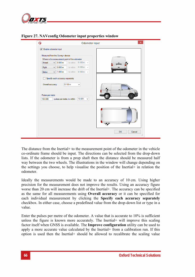
66 Oxford Technical Solutions
Figure 27. NAVconfig Odometer input properties window
The distance from the Inertial+ to the measurement point of the odometer in the vehicle co-ordinate frame should be input. The directions can be selected from the drop-down lists. If the odometer is from a prop shaft then the distance should be measured half way between the two wheels. The illustrations in the window will change depending on the settings you choose, to help visualise the position of the Inertial+ in relation the odometer.
Ideally the measurements would be made to an accuracy of 10 cm. Using higher precision for the measurement does not improve the results. Using an accuracy figure worse than 20 cm will increase the drift of the Inertial+. The accuracy can be specified as the same for all measurements using Overall accuracy or it can be specified for each individual measurement by clicking the Specify each accuracy separately checkbox. In either case, choose a predefined value from the drop-down list or type in a value.
Enter the pulses per metre of the odometer. A value that is accurate to 10% is sufficient unless the figure is known more accurately. The Inertial+ will improve this scaling factor itself when GNSS is available. The Improve configuration utility can be used to apply a more accurate value calculated by the Inertial+ from a calibration run. If this option is used then the Inertial+ should be allowed to recalibrate the scaling value
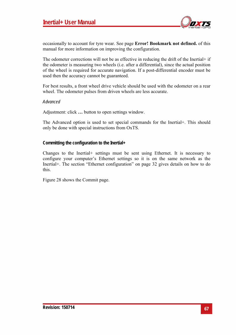
Inertial+ User Manual
Revision: 150714 67
occasionally to account for tyre wear. See page Error! Bookmark not defined. of this manual for more information on improving the configuration.
The odometer corrections will not be as effective in reducing the drift of the Inertial+ if the odometer is measuring two wheels (i.e. after a differential), since the actual position of the wheel is required for accurate navigation. If a post-differential encoder must be used then the accuracy cannot be guaranteed.
For best results, a front wheel drive vehicle should be used with the odometer on a rear wheel. The odometer pulses from driven wheels are less accurate.
Advanced
Adjustment: click … button to open settings window.
The Advanced option is used to set special commands for the Inertial+. This should only be done with special instructions from OxTS.
Committing the configuration to the Inertial+
Changes to the Inertial+ settings must be sent using Ethernet. It is necessary to configure your computer’s Ethernet settings so it is on the same network as the Inertial+. The section “Ethernet configuration” on page 32 gives details on how to do this.
Figure 28 shows the Commit page.
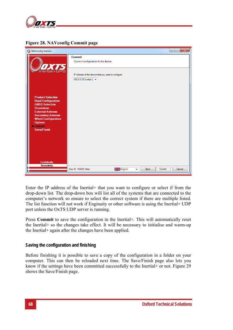
68 Oxford Technical Solutions
Figure 28. NAVconfig Commit page
Enter the IP address of the Inertial+ that you want to configure or select if from the drop-down list. The drop-down box will list all of the systems that are connected to the computer’s network so ensure to select the correct system if there are multiple listed. The list function will not work if Enginuity or other software is using the Inertial+ UDP port unless the OxTS UDP server is running.
Press Commit to save the configuration in the Inertial+. This will automatically reset the Inertial+ so the changes take effect. It will be necessary to initialise and warm-up the Inertial+ again after the changes have been applied.
Saving the configuration and finishing
Before finishing it is possible to save a copy of the configuration in a folder on your computer. This can then be reloaded next time. The Save/Finish page also lets you know if the settings have been committed successfully to the Inertial+ or not. Figure 29 shows the Save/Finish page.
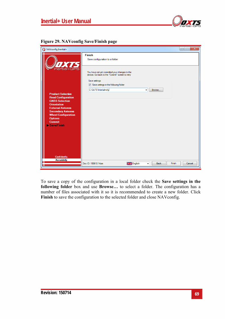
Inertial+ User Manual
Revision: 150714 69
Figure 29. NAVconfig Save/Finish page
To save a copy of the configuration in a local folder check the Save settings in the following folder box and use Browse… to select a folder. The configuration has a number of files associated with it so it is recommended to create a new folder. Click Finish to save the configuration to the selected folder and close NAVconfig.
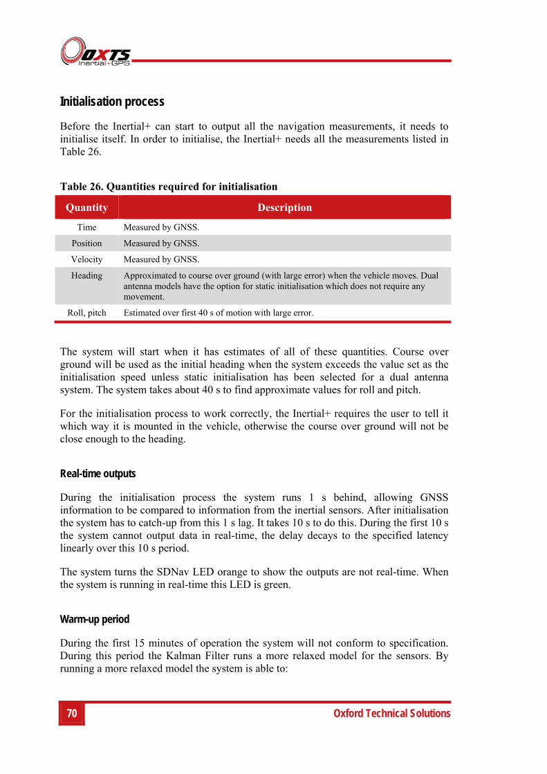
70 Oxford Technical Solutions
Initialisation process
Before the Inertial+ can start to output all the navigation measurements, it needs to initialise itself. In order to initialise, the Inertial+ needs all the measurements listed in Table 26.
Table 26. Quantities required for initialisation
Quantity Description
Time Measured by GNSS.
Position Measured by GNSS.
Velocity Measured by GNSS.
Heading Approximated to course over ground (with large error) when the vehicle moves. Dual antenna models have the option for static initialisation which does not require any movement.
Roll, pitch Estimated over first 40 s of motion with large error.
The system will start when it has estimates of all of these quantities. Course over ground will be used as the initial heading when the system exceeds the value set as the initialisation speed unless static initialisation has been selected for a dual antenna system. The system takes about 40 s to find approximate values for roll and pitch.
For the initialisation process to work correctly, the Inertial+ requires the user to tell it which way it is mounted in the vehicle, otherwise the course over ground will not be close enough to the heading.
Real-time outputs
During the initialisation process the system runs 1 s behind, allowing GNSS information to be compared to information from the inertial sensors. After initialisation the system has to catch-up from this 1 s lag. It takes 10 s to do this. During the first 10 s the system cannot output data in real-time, the delay decays to the specified latency linearly over this 10 s period.
The system turns the SDNav LED orange to show the outputs are not real-time. When the system is running in real-time this LED is green.
Warm-up period
During the first 15 minutes of operation the system will not conform to specification. During this period the Kalman Filter runs a more relaxed model for the sensors. By running a more relaxed model the system is able to:
Inertial+ User Manual
Revision: 150714 71
1. Make better estimates of the errors in the long term (if it does not get these correct then they become more difficult to correct as time goes on).
2. Track the errors in the inertial sensor during their warm-up period (when their errors change more quickly than normal).
During this period it is necessary to drive the vehicle or the errors will not be estimated and the specification will not be reached. The NCOM output message includes status information that can be used to identify when the required specification has been met. These are plotted in the example below.
The warm-up period is a concern to some customers but it is often very simple to overcome. Below is an example of a good warm-up procedure that did not involve a lot of work for the user. In this example the key features are:
The Inertial+ was configured well—the GNSS antenna position, Wheel configuration options and dual antenna separation were measured accurately in advance.
The Inertial+ was turned on as soon as possible. In this case it took us 15 minutes to get all the other equipment sorted out. The Inertial+ was stationary for most of this period—which is not a problem.
Although in this example the Inertial+ was receiving corrections from a base-station while stationary, it is not necessary. The base-station should be working before the dynamic driving starts so the Inertial+ can use the best information to self-calibrate (if a base-station is not being use this does not apply).
There are 6 minutes during which the vehicle was driven in figures of eight. From the graphs you can see the Inertial+ is accurate almost after the first figure of eight, after that the improvement is very small.
The trick is to turn the Inertial+ on early, do not reconfigure it (which resets it) or cycle the power.
Figure 30 shows the route driven and Figure 31 shows the accuracy estimated by the Kalman filter for various output parameters during the first 25 minutes. The quality of initialisation would have been the same if the stationary period was 10 minutes, followed by 5 minutes of driving. The time on the graphs is the time from initialisation. In this example the Inertial+ was initialised 25 s after starting up; the quality of initialisation would be the same if it had been not been initialised for the first 10 minutes, then initialised and driven for 5 minutes.
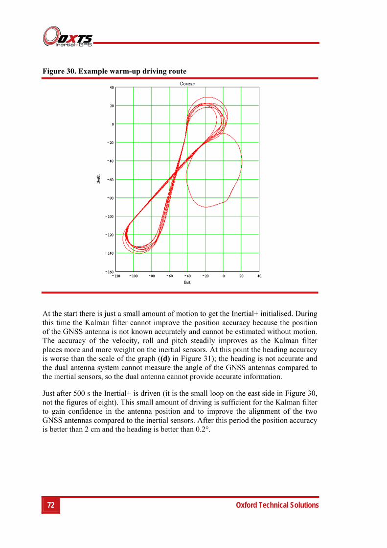
72 Oxford Technical Solutions
Figure 30. Example warm-up driving route
At the start there is just a small amount of motion to get the Inertial+ initialised. During this time the Kalman filter cannot improve the position accuracy because the position of the GNSS antenna is not known accurately and cannot be estimated without motion. The accuracy of the velocity, roll and pitch steadily improves as the Kalman filter places more and more weight on the inertial sensors. At this point the heading accuracy is worse than the scale of the graph ((d) in Figure 31); the heading is not accurate and the dual antenna system cannot measure the angle of the GNSS antennas compared to the inertial sensors, so the dual antenna cannot provide accurate information.
Just after 500 s the Inertial+ is driven (it is the small loop on the east side in Figure 30, not the figures of eight). This small amount of driving is sufficient for the Kalman filter to gain confidence in the antenna position and to improve the alignment of the two GNSS antennas compared to the inertial sensors. After this period the position accuracy is better than 2 cm and the heading is better than 0.2°.
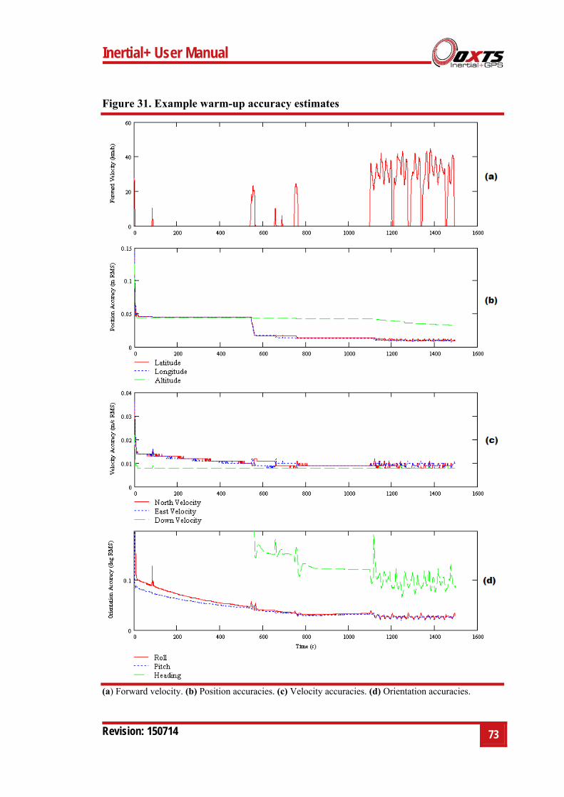
Inertial+ User Manual
Revision: 150714 73
Figure 31. Example warm-up accuracy estimates
(a) Forward velocity. (b) Position accuracies. (c) Velocity accuracies. (d) Orientation accuracies.
74 Oxford Technical Solutions
You can see the Inertial+ is nearly at specification after just this small amount of driving. However, experience tells us the Kalman filter will continue to make some improvements (not obvious) during the first few figures of eight. The main part of the motion occurs after 1100 s when the vehicle was driven in a figure of eight for 6 minutes.
These are fairly large figures of eight driven at relatively low speeds. Notice the brake stops in the velocity graph ((a) in Figure 31) where the speed falls to zero. These are important parts of the warm-up—so as many states in the Kalman filter as possible can be updated.
Notice how close to the specification the Inertial+ is even without the figure of eight manoeuvres. Warm-up is recommended in order to achieve the highest level of accuracy. In aircraft applications, flying figures of eight will remove a few hundredths of a degree of roll and pitch error—which can be critical for geo-referencing applications. The same is true for marine applications. However the effect is small and only significant when you need the full performance of the Inertial+.

Inertial+ User Manual
Revision: 150714 75
Post-processing data
Data stored on the Inertial+ is in a raw, unprocessed format; these files have an RD extension. The advantage of this is it can be reprocessed with different configuration settings. For example, if the configuration was configured incorrectly when running in real-time, then the configuration can be changed and the data can be reprocessed post-mission.
The software suite provided with the Inertial+ includes the RT Post-process software which can be used to reprocess the data. The RT Post-process Wizard also gives the user the ability to change the NCOM binary output format to text.
A full explanation of RT Post-process is given in the RT Post-process manual.
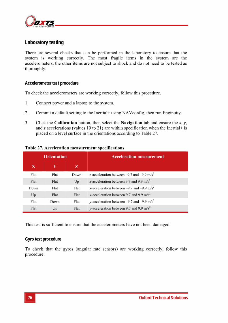
76 Oxford Technical Solutions
Laboratory testing
There are several checks that can be performed in the laboratory to ensure that the system is working correctly. The most fragile items in the system are the accelerometers, the other items are not subject to shock and do not need to be tested as thoroughly.
Accelerometer test procedure
To check the accelerometers are working correctly, follow this procedure.
1. Connect power and a laptop to the system.
2. Commit a default setting to the Inertial+ using NAVconfig, then run Enginuity.
3. Click the Calibration button, then select the Navigation tab and ensure the x, y, and z accelerations (values 19 to 21) are within specification when the Inertial+ is placed on a level surface in the orientations according to Table 27.
Table 27. Acceleration measurement specifications
Orientation Acceleration measurement
X Y Z
Flat Flat Down z-acceleration between –9.7 and –9.9 m/s2
Flat Flat Up z-acceleration between 9.7 and 9.9 m/s2
Down Flat Flat x-acceleration between –9.7 and –9.9 m/s2
Up Flat Flat x-acceleration between 9.7 and 9.9 m/s2
Flat Down Flat y-acceleration between –9.7 and –9.9 m/s2
Flat Up Flat y-acceleration between 9.7 and 9.9 m/s2
This test is sufficient to ensure that the accelerometers have not been damaged.
Gyro test procedure
To check that the gyros (angular rate sensors) are working correctly, follow this procedure:
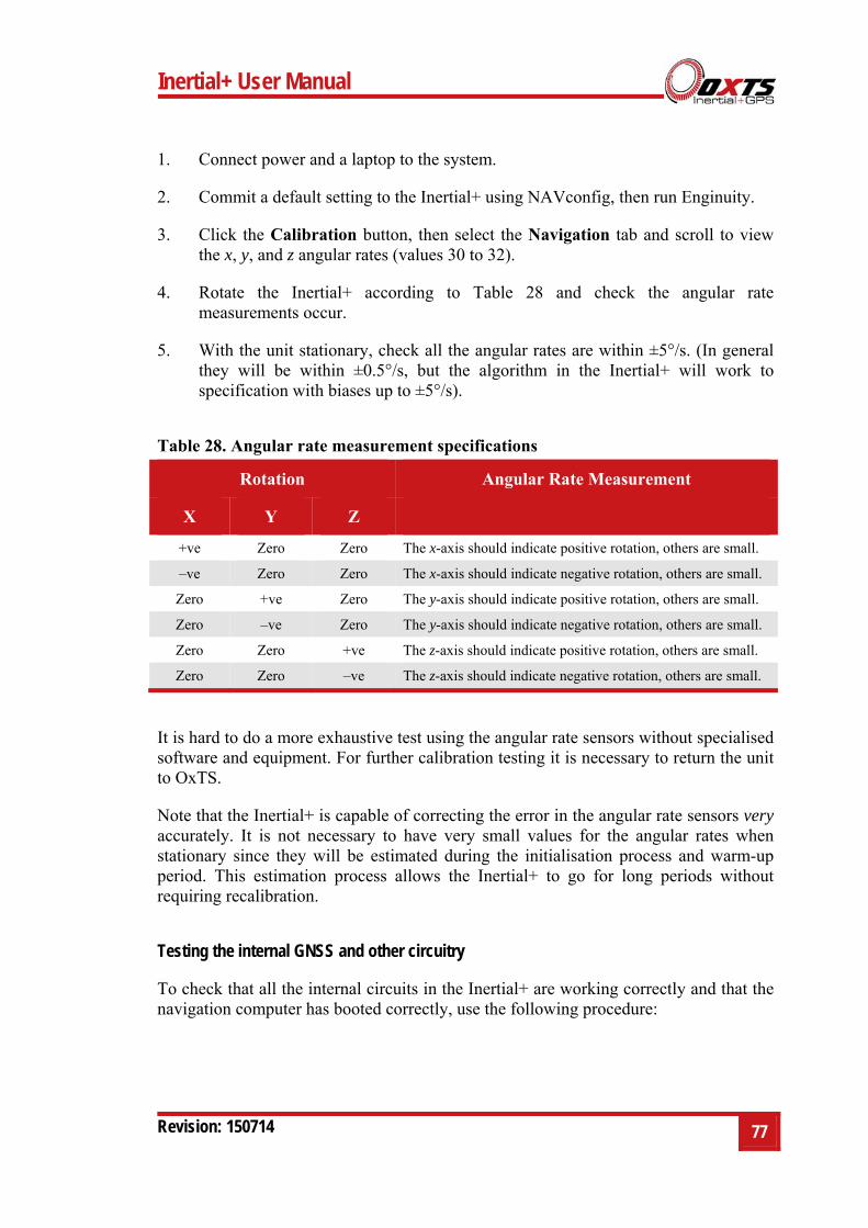
Inertial+ User Manual
Revision: 150714 77
1. Connect power and a laptop to the system.
2. Commit a default setting to the Inertial+ using NAVconfig, then run Enginuity.
3. Click the Calibration button, then select the Navigation tab and scroll to view the x, y, and z angular rates (values 30 to 32).
4. Rotate the Inertial+ according to Table 28 and check the angular rate measurements occur.
5. With the unit stationary, check all the angular rates are within ±5°/s. (In general they will be within ±0.5°/s, but the algorithm in the Inertial+ will work to specification with biases up to ±5°/s).
Table 28. Angular rate measurement specifications
Rotation Angular Rate Measurement
X Y Z
+ve Zero Zero The x-axis should indicate positive rotation, others are small.
–ve Zero Zero The x-axis should indicate negative rotation, others are small.
Zero +ve Zero The y-axis should indicate positive rotation, others are small.
Zero –ve Zero The y-axis should indicate negative rotation, others are small.
Zero Zero +ve The z-axis should indicate positive rotation, others are small.
Zero Zero –ve The z-axis should indicate negative rotation, others are small.
It is hard to do a more exhaustive test using the angular rate sensors without specialised software and equipment. For further calibration testing it is necessary to return the unit to OxTS.
Note that the Inertial+ is capable of correcting the error in the angular rate sensors very accurately. It is not necessary to have very small values for the angular rates when stationary since they will be estimated during the initialisation process and warm-up period. This estimation process allows the Inertial+ to go for long periods without requiring recalibration.
Testing the internal GNSS and other circuitry
To check that all the internal circuits in the Inertial+ are working correctly and that the navigation computer has booted correctly, use the following procedure:
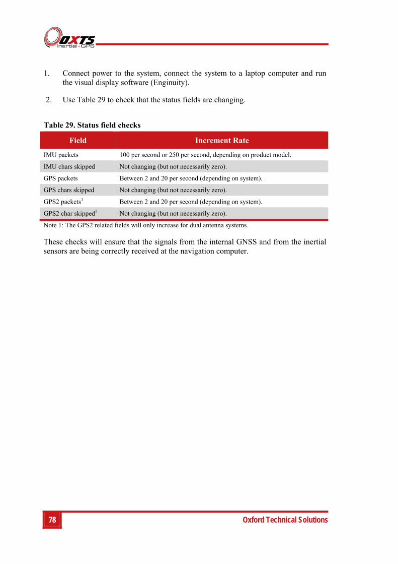
78 Oxford Technical Solutions
1. Connect power to the system, connect the system to a laptop computer and run the visual display software (Enginuity).
2. Use Table 29 to check that the status fields are changing.
Table 29. Status field checks
Field Increment Rate
IMU packets 100 per second or 250 per second, depending on product model.
IMU chars skipped Not changing (but not necessarily zero).
GPS packets Between 2 and 20 per second (depending on system).
GPS chars skipped Not changing (but not necessarily zero).
GPS2 packets1 Between 2 and 20 per second (depending on system).
GPS2 char skipped1 Not changing (but not necessarily zero).
Note 1: The GPS2 related fields will only increase for dual antenna systems.
These checks will ensure that the signals from the internal GNSS and from the inertial sensors are being correctly received at the navigation computer.

Inertial+ User Manual
Revision: 150714 79
Using the orientation measurements
This section has been provided to clarify the definitions of heading, pitch and roll that are output by the Inertial+.
The Inertial+ uses quaternions internally to avoid the problems of singularities and to minimise numerical drift on the attitude integration. Euler angles are used to output the heading, pitch and roll, and these have singularities at two orientations. The Inertial+ has rules to avoid problems when operating close to the singularities; if you regenerate the rotation matrices given below then they will be correct.
The Euler angles output are three consecutive rotations (first heading, then pitch and finally roll) that transform a vector measured in the navigation co-ordinate frame to the body co-ordinate frame. The navigation co-ordinate frame is the orientation on the earth at your current location with axes of north, east and down.
If is vector measured in the navigation co-ordinate frame and is the same
vector measured in the body co-ordinate frame the two vectors are related by:
where:
is the heading angle; is the pitch angle and is the roll angle.
Remember – heading, pitch and roll are usually output in degrees, but the functions sin and cos require these values in radians.
V n V V b
V n C bn V b
V n
cos ( )
sin ( )
0
sin ( )
cos ( )
0
0
0
1
cos ( )
0
sin ( )
0
1
0
sin ( )
0
cos ( )
1
0
0
0
cos ( )
sin ( )
0
sin ( )
cos ( )
V b
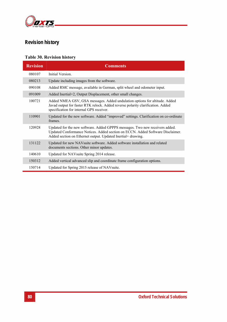
80 Oxford Technical Solutions
Revision history
Table 30. Revision history
Revision Comments
080107 Initial Version.
080213 Update including images from the software.
090108 Added RMC message, available in German, split wheel and odometer input.
091009 Added Inertial+2, Output Displacement, other small changes.
100721 Added NMEA GSV, GSA messages. Added undulation options for altitude. Added Javad output for faster RTK relock. Added reverse polarity clarification. Added specification for internal GPS receiver.
110901 Updated for the new software. Added “improved” settings. Clarification on co-ordinate frames.
120928 Updated for the new software. Added GPPPS messages. Two new receivers added. Updated Conformance Notices. Added section on ECCN. Added Software Disclaimer. Added section on Ethernet output. Updated Inertial+ drawing.
131122 Updated for new NAVsuite software. Added software installation and related documents sections. Other minor updates.
140610 Updated for NAVsuite Spring 2014 release.
150312 Added vertical advanced slip and coordinate frame configuration options.
150714 Updated for Spring 2015 release of NAVsuite.
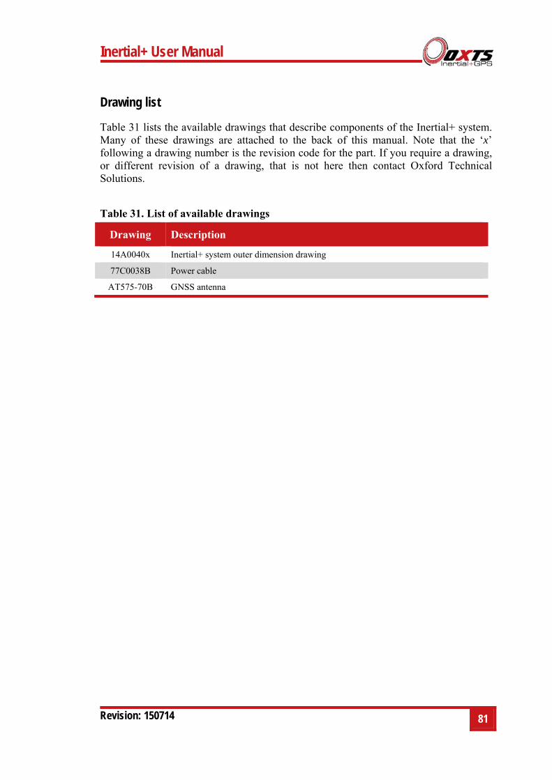
Inertial+ User Manual
Revision: 150714 81
Drawing list
Table 31 lists the available drawings that describe components of the Inertial+ system. Many of these drawings are attached to the back of this manual. Note that the ‘x’ following a drawing number is the revision code for the part. If you require a drawing, or different revision of a drawing, that is not here then contact Oxford Technical Solutions.
Table 31. List of available drawings
Drawing Description
14A0040x Inertial+ system outer dimension drawing
77C0038B Power cable
AT575-70B GNSS antenna
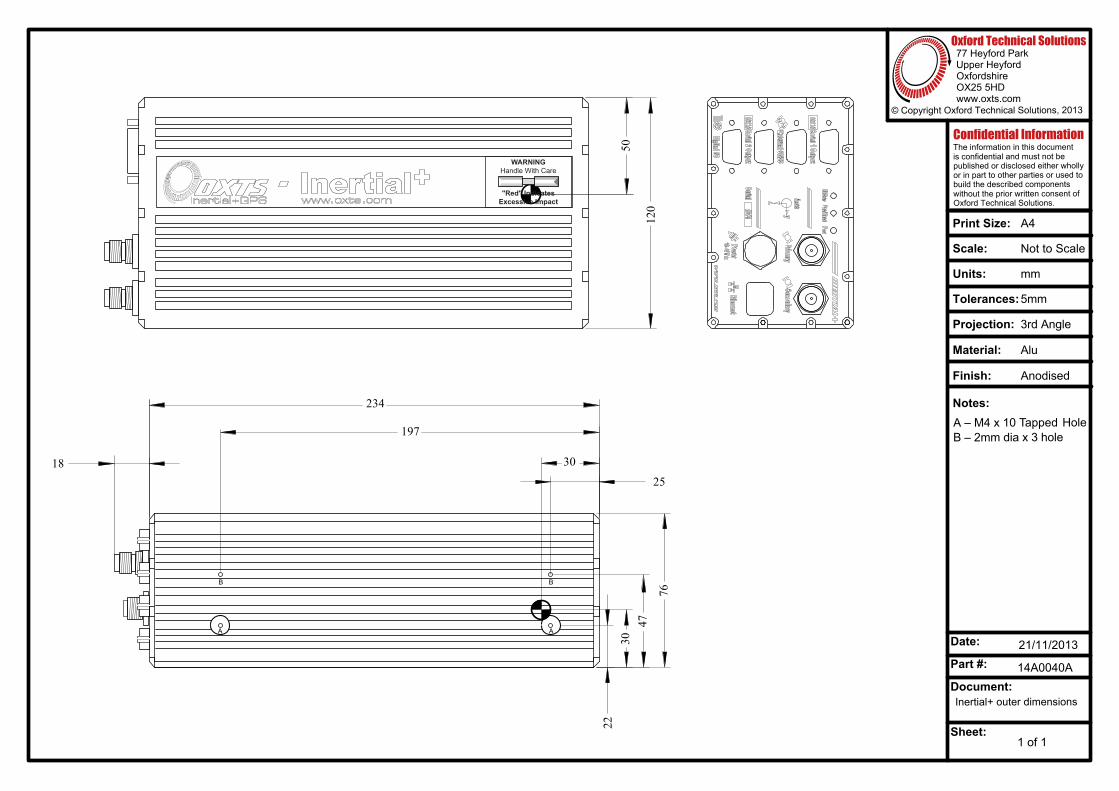
Units:
Tolerances:
Scale:
© Copyright Oxford Technical Solutions, 2013
mm
A4Print Size:
Date:
Part #:
Document:
Sheet:
77 Heyford ParkUpper HeyfordOxfordshireOX25 5HDwww.oxts.com
Oxford Technical Solutions
Not to Scale
Confidential InformationThe information in this documentis confidential and must not bepublished or disclosed either whollyor in part to other parties or used tobuild the described components without the prior written consent ofOxford Technical Solutions.
Notes:
21/11/2013
Inertial+ outer dimensions
14A0040A
1 of 1
5mm
Projection:
Material:
Finish:
3rd Angle
Alu
Anodised
120
50
76
2230
47
234
25
30
197
18
WARNINGHandle With Care
"Red" IndicatesExcessive Impact
OXTSInertial+GPS
- www.oxts.comInertial+
A – M4 x 10 Tapped HoleB – 2mm dia x 3 hole
A A
BB
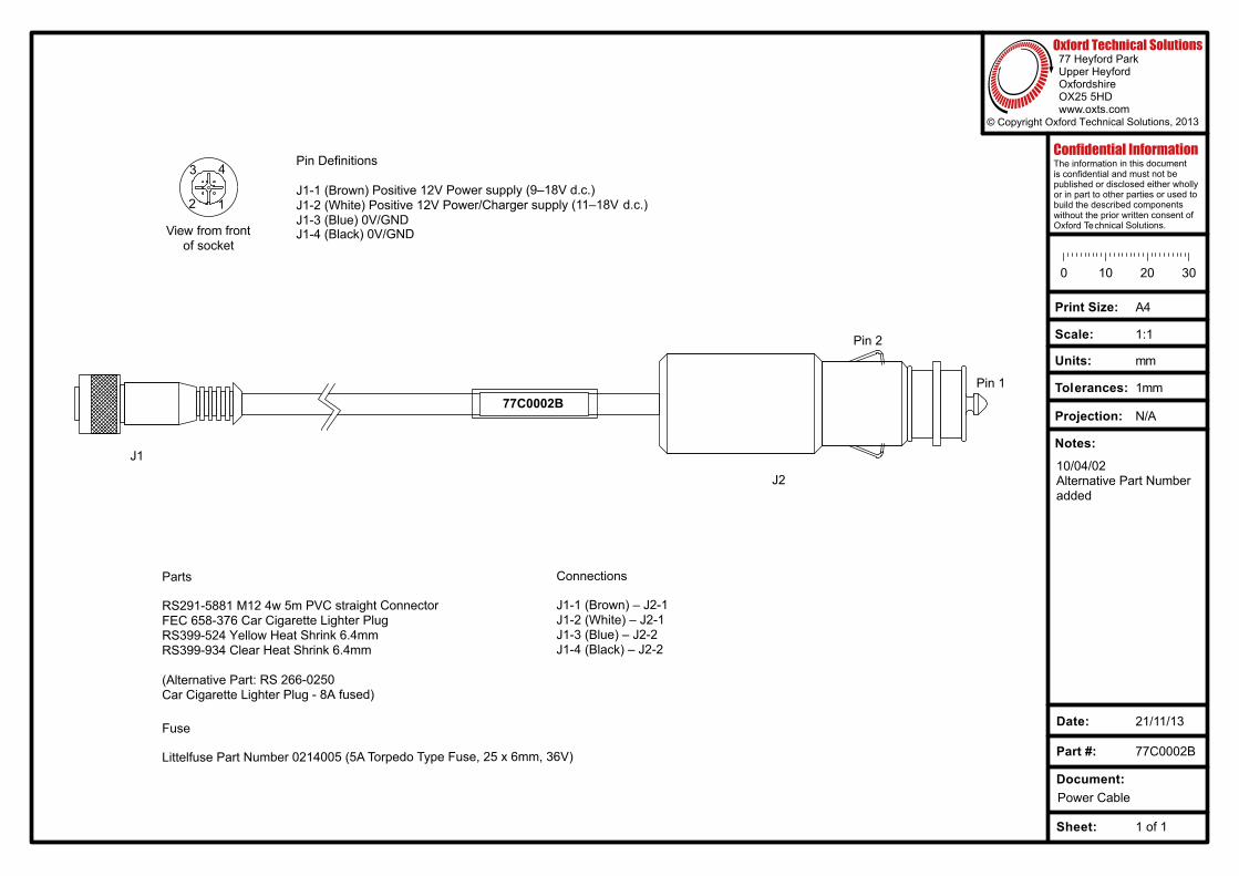
© Copyright Oxford Technical Solutions, 2013
77 Heyford ParkUpper HeyfordOxfordshireOX25 5HDwww.oxts.com
Oxford Technical Solutions
77C0002B
Parts
RS291-5881 M12 4w 5m PVC straight ConnectorFEC 658-376 Car Cigarette Lighter PlugRS399-524 Yellow Heat Shrink 6.4mmRS399-934 Clear Heat Shrink 6.4mm
(Alternative Part: RS 266-0250Car Cigarette Lighter Plug - 8A fused)
Connections
J1-1 (Brown) – J2-1J1-2 (White) – J2-1J1-3 (Blue) – J2-2J1-4 (Black) – J2-2
J1
J2
Pin 2
Pin 1
1
43
2
View from frontof socket
Pin Definitions
J1-1 (Brown) Positive 12V Power supply (9–18V d.c.)J1-2 (White) Positive 12V Power/Charger supply (11–18V d.c.)J1-3 (Blue) 0V/GNDJ1-4 (Black) 0V/GND
Confidential InformationThe information in this documentis confidential and must not bepublished or disclosed either whollyor in part to other parties or used to build the described components without the prior written consent ofOxford Technical Solutions.
Sheet: 1 of 1
Document:
Part #:
Date:
0 10 20 30
Print Size:
Scale:
Units:
Tolerances:
Projection:
A4
1:1
mm
1mm
N/A
Notes:
21/11/13
77C0002B
Power Cable
10/04/02Alternative Part Numberadded
Fuse
Littelfuse Part Number 0214005 (5A Torpedo Type Fuse, 25 x 6mm, 36V)
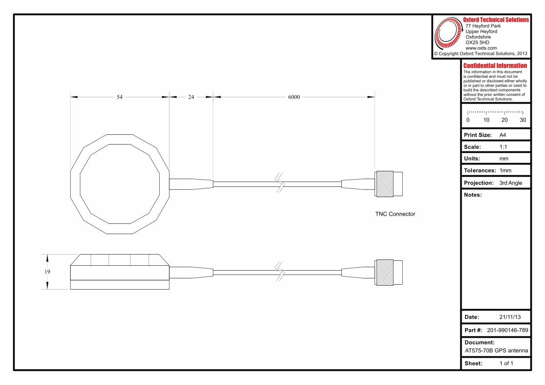
© Copyright Oxford Technical Solutions, 2013
77 Heyford ParkUpper HeyfordOxfordshireOX25 5HDwww.oxts.com
Oxford Technical Solutions
Confidential InformationThe information in this documentis confidential and must not bepublished or disclosed either whollyor in part to other parties or used to build the described components without the prior written consent ofOxford Technical Solutions.
Sheet: 1 of 1
Document:
Part #:
Date:
0 10 20 30
Print Size:
Scale:
Units:
Tolerances:
Projection:
A4
1:1
mm
1mm
3rd Angle
Notes:
21/11/13
201-990146-789
AT575-70B GPS antenna
54 24 6000
19
TNC Connector