Embed Size (px)
Citation preview
lable at ScienceDirect
Journal of Loss Prevention in the Process Industries 22 (2009) 791–794
Contents lists avai
Journal of Loss Prevention in the Process Industries
journal homepage: www.elsevier .com/locate/ j lp
Inerted vessels: Avoiding hazards caused by gas buoyancy
J.C. Ramirez, D.J. Eby, D.B. Bullen, A.R. Carpenter, R.A. Ogle*
Exponent Failure Analysis Associates, 1011 Warrenville Road, Suite 215, Lisle, IL 60532, USA
a r t i c l e i n f o
Article history:Received 16 January 2009Received in revised form21 July 2009Accepted 28 July 2009
Keywords:Hot workPurgeVesselInert gasBuoyancy
* Corresponding author. Tel.: þ1 630 743 7700.E-mail address: [email protected] (R.A. Ogle).
0950-4230/$ – see front matter � 2009 Elsevier Ltd.doi:10.1016/j.jlp.2009.07.016
a b s t r a c t
Performing hot work on a process vessel that previously contained a flammable hydrocarbon liquid posesa significant explosion and fire hazard. To reduce the combustion hazard potential, the facility operator maychoose to purge and blanket the vessel with an inert gas such as nitrogen or carbon dioxide. Numerousaccidents have occurred during hot work due to inadequate inerting operations. Oftentimes the source ofthe problem was inadequate gas composition control caused by gas buoyancy.
A useful paradigm for analyzing the inerting process is the well-stirred control volume with a spatiallyuniform chemical composition (i.e., perfect mixing). Certain features of the vessel construction, inconcert with the physical properties of the inert gas, can interfere with the complete mixing of the inertgas with the vessel atmosphere. This paper discusses how to evaluate the potential for buoyant flows todisrupt and interfere with the design goal of perfect mixing. Three case studies of accident investigationsare used to illustrate the potentially detrimental effects of buoyancy on inerting operations. Finally,recommendations are presented on how to use buoyancy to improve the effectiveness of inertingoperations.
� 2009 Elsevier Ltd. All rights reserved.
1. Introduction
In this paper, we examine the effects of natural convection(buoyancy) on purging and blanketing of process vessels. Purgingand blanketing are terms applied respectively to the removal orprevention of a combustible mixture in a vessel. For the purposes ofthis paper, the term ‘‘inerting’’ is used as an umbrella term to coverboth purging and blanketing. Buoyancy (flow induced by tempera-ture and/or density gradients) can inducedor prevent the formationofdflow patterns inside inerted vessels. Not considering these flowpatterns can lead to improperly inerted vessels and potentiallydisastrous consequences. Conversely, an understanding of buoyancyallows its use as a tool for effective inerting of process vessels.
The paper is divided into several sections. First we discuss thehazards, applicable layers of protection, and safety standards rele-vant to hot work near inerted vessels. Section 3 describes a designstrategy for vessel inerting and then discusses factors that influencethe effectiveness of concentration control. In Section 4 we discussthe phenomenon of natural convection, the typical geometricproperties of process vessels that influence the development ofbuoyant flows inside them, and the densimetric Froude number, thedimensionless number that is useful in predicting the significance ofbuoyancy. In Section 5, we present accident case studies involving
All rights reserved.
the formation of unexpected pockets of air, the formation of stagnantpockets of flammable gas, and density stratification. In Section 6 weprovide recommendations on how to use buoyancy to improve theeffectiveness of inerting operations.
2. Hot work safety and process vessels
The National Fire Protection Association (NFPA) defines hot workas ‘‘any work involving burning, welding or similar operations that iscapable of initiating fires or explosions’’ (NFPA 51B, 2003). Since hotwork presents a high-strength, sustained ignition source capable ofigniting many fuels, hot work safety is of paramount importance toany industrial safety program.
A vessel or container holding a flammable vapor–air mixture isa major hazard. If said mixture is ignited, the vessel or containercan explode, causing death or serious injuries. In chemical processindustries, typically large inventories of hazardous chemicals storedonsite are thus exposed to the event of fire or explosion. The hazardsof hot work near improperly inerted vessels have been previouslydocumented (see Morrison, Carpenter, & Ogle, 2002, and Ogle &Carpenter, 2001).
In the process of inerting, the flammable contents are vented toa location outside the vessel. Personnel should take special care toavoid producing flammable vapor clouds near the vessel. For thisreason, the strategy of designing/selecting inerting methods mustextend beyond the immediate vessel to ensure safe operatingconditions.
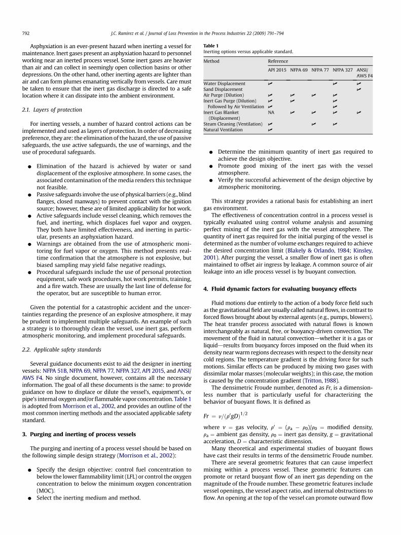
Table 1Inerting options versus applicable standard.
Method Reference
API 2015 NFPA 69 NFPA 77 NFPA 327 ANSI/AWS F4
Water Displacement U U U
Sand Displacement U
Air Purge (Dilution) U U U U
Inert Gas Purge (Dilution) U U U
Followed by Air Ventilation U U
Inert Gas Blanket(Displacement)
NA U U U U
Steam Cleaning (Ventilation) U U U
Natural Ventilation U
J.C. Ramirez et al. / Journal of Loss Prevention in the Process Industries 22 (2009) 791–794792
Asphyxiation is an ever-present hazard when inerting a vessel formaintenance. Inert gases present an asphyxiation hazard to personnelworking near an inerted process vessel. Some inert gases are heavierthan air and can collect in seemingly open collection basins or otherdepressions. On the other hand, other inerting agents are lighter thanair and can form plumes emanating vertically from vessels. Care mustbe taken to ensure that the inert gas discharge is directed to a safelocation where it can dissipate into the ambient environment.
2.1. Layers of protection
For inerting vessels, a number of hazard control actions can beimplemented and used as layers of protection. In order of decreasingpreference, they are: the elimination of the hazard, the use of passivesafeguards, the use active safeguards, the use of warnings, and theuse of procedural safeguards.
C Elimination of the hazard is achieved by water or sanddisplacement of the explosive atmosphere. In some cases, theassociated contamination of the media renders this techniquenot feasible.
C Passive safeguards involve the use of physical barriers (e.g., blindflanges, closed manways) to prevent contact with the ignitionsource; however, these are of limited applicability for hot work.
C Active safeguards include vessel cleaning, which removes thefuel, and inerting, which displaces fuel vapor and oxygen.They both have limited effectiveness, and inerting in partic-ular, presents an asphyxiation hazard.
C Warnings are obtained from the use of atmospheric moni-toring for fuel vapor or oxygen. This method presents real-time confirmation that the atmosphere is not explosive, butbiased sampling may yield false negative readings.
C Procedural safeguards include the use of personal protectionequipment, safe work procedures, hot work permits, training,and a fire watch. These are usually the last line of defense forthe operator, but are susceptible to human error.
Given the potential for a catastrophic accident and the uncer-tainties regarding the presence of an explosive atmosphere, it maybe prudent to implement multiple safeguards. An example of sucha strategy is to thoroughly clean the vessel, use inert gas, performatmospheric monitoring, and implement procedural safeguards.
2.2. Applicable safety standards
Several guidance documents exist to aid the designer in inertingvessels: NFPA 51B, NFPA 69, NFPA 77, NFPA 327, API 2015, and ANSI/AWS F4. No single document, however, contains all the necessaryinformation. The goal of all these documents is the same: to provideguidance on how to displace or dilute the vessel’s, equipment’s, orpipe’s internal oxygen and/or flammable vapor concentration. Table 1is adopted from Morrison et al., 2002, and provides an outline of themost common inerting methods and the associated applicable safetystandard.
3. Purging and inerting of process vessels
The purging and inerting of a process vessel should be based onthe following simple design strategy (Morrison et al., 2002):
C Specify the design objective: control fuel concentration tobelow the lower flammability limit (LFL) or control the oxygenconcentration to below the minimum oxygen concentration(MOC).
C Select the inerting medium and method.
C Determine the minimum quantity of inert gas required toachieve the design objective.
C Promote good mixing of the inert gas with the vesselatmosphere.
C Verify the successful achievement of the design objective byatmospheric monitoring.
This strategy provides a rational basis for establishing an inertgas environment.
The effectiveness of concentration control in a process vessel istypically evaluated using control volume analysis and assumingperfect mixing of the inert gas with the vessel atmosphere. Thequantity of inert gas required for the initial purging of the vessel isdetermined as the number of volume exchanges required to achievethe desired concentration limit (Blakely & Orlando, 1984; Kinsley,2001). After purging the vessel, a smaller flow of inert gas is oftenmaintained to offset air ingress by leakage. A common source of airleakage into an idle process vessel is by buoyant convection.
4. Fluid dynamic factors for evaluating buoyancy effects
Fluid motions due entirely to the action of a body force field suchas the gravitational field are usually called natural flows, in contrast toforced flows brought about by external agents (e.g., pumps, blowers).The heat transfer process associated with natural flows is knowninterchangeably as natural, free, or buoyancy-driven convection. Themovement of the fluid in natural convectiondwhether it is a gas orliquiddresults from buoyancy forces imposed on the fluid when itsdensity near warm regions decreases with respect to the density nearcold regions. The temperature gradient is the driving force for suchmotions. Similar effects can be produced by mixing two gases withdissimilar molar masses (molecular weights); in this case, the motionis caused by the concentration gradient (Tritton, 1988).
The densimetric Froude number, denoted as Fr, is a dimension-less number that is particularly useful for characterizing thebehavior of buoyant flows. It is defined as
Fr ¼ v=ðr0gDÞ1=2
where v ¼ gas velocity, r0 ¼ (ra � r0)/r0 ¼ modified density,ra ¼ ambient gas density, r0 ¼ inert gas density, g ¼ gravitationalacceleration, D ¼ characteristic dimension.
Many theoretical and experimental studies of buoyant flowshave cast their results in terms of the densimetric Froude number.
There are several geometric features that can cause imperfectmixing within a process vessel. These geometric features canpromote or retard buoyant flow of an inert gas depending on themagnitude of the Froude number. These geometric features includevessel openings, the vessel aspect ratio, and internal obstructions toflow. An opening at the top of the vessel can promote outward flow
J.C. Ramirez et al. / Journal of Loss Prevention in the Process Industries 22 (2009) 791–794 793
of an inert gas if it is positively buoyant (lighter than air). The sameopening would not promote buoyant flow if the inert gas hasnegative buoyancy (heavier than air). Similarly, vessels with largeaspect (height to diameter) ratios will promote positive buoyancy.Internal obstructions can likewise influence buoyant flow.
5. Case studies: accidents involving buoyancy-induceddepartures from perfect mixing
The case studies discussed in this section illustrate how buoyantflows can interfere with the design objective of creating a uniformlylow concentration of either fuel or oxygen in the process vessel. Inone of the case studies a buoyant flow introduced air into an inertedvessel. In the other two cases, stable density stratification of fuelvapor defeated efforts to purge or blanket the vessel.
5.1. Unexpected intrusion of air into a vessel withan inert atmosphere blanket
Maintenance was being performed on a surge tank for holdingpolypropylene powder. The surge tank was normally blanketed withnitrogen gas due to the concern of residual propylene gas potentiallyaccumulating in the vessel. The surge tank was a tall cylindrical vesselwith an aspect ratio of approximately three. Workers opened a man-way located on the vessel wall; the manway was at an elevation ofapproximately two-thirds the height of the vessel. The maintenancetask was to remove the powder from the surge tank using a hose froma vacuum truck.
In preparation for maintenance, the nitrogen gas had beenblanked off. The manway remained open for several hours. The openmanway allowed air, the heavier gas, to enter and displace some ofthe nitrogen gas in the tank. A contractor employee began to removethe powder from the tank using the vacuum hose. He was suddenlyengulfed in a flash fire and subsequently died from his injuries.Smoking materials, strictly forbidden from use in the work area,were found nearby. It was determined that sufficient air had enteredthe surge tank to form a flammable mixture with residual propylenegas and polypropylene powder.
Nitrogen gas is lighter than air. To prevent the intrusion of theheavier air through the open manway, the flow of nitrogen mustsatisfy the criterion that Fr > 1 (Lee & Chu, 2003). At lower Froudenumbers, the flow of nitrogen gas occupies only the upper portion ofthe manway and the counterflow of air occupies the lower portion.As the intruding air stream mixed with the atmosphere within thetank, it created a flammable atmosphere. Thus, for this accident tooccur, the Froude number of the nitrogen gas discharge had to beless than unity.
5.2. Internal obstruction creates a stagnant pocket of flammable gas
Paint was being removed from the manway of a reactor vesselthat had recently contained ethylene oxide. The facility was a PSM-covered facility (i.e., a facility that must comply with the processsafety management regulations promulgated under the U.S. Occu-pational Safety and Health Administration) that manufacturedspecialty chemicals. The paint was being removed with an electricgrinder by an outside contractor. The contractor was experiencedwith the grinding equipment and familiar with the facility. Thecontractor was assisted by a facility employee. The manway wasopen during the grinding.
The tank was blanketed with nitrogen and the plant employeeacted as a fire watch during the grinding. A hot work permit wasissued, and both oxygen and combustible gas indicator (CGI)measurements were taken at the start of the work. When CGI readingswere taken, the sample tube did not reach the bottom of the tank.
Additionally, an abandoned pipe that connected to the bottom of thevessel was not identified. It was determined during the course of theaccident investigation that this abandoned pipe contained ethyleneoxide. Ethylene oxide does not require additional oxygen to burn.Sparks from the grinder ignited the ethylene oxide that remained inthe bottom of the tank, resulting in a flash fire. The contractor receivedfatal burns.
The direct cause of this accident was the failure to remove thedead-end pipe from the vessel. A blinded pipe section on a vessel willtend to be a stagnant zone where material can accumulate. In thiscase, the ethylene oxide ‘‘hid’’ in the blinded pipe section during thenitrogen purge. The ethylene oxide, which is denser than nitrogen,eventually migrated out of the pipe through a process of naturalconvection and diffusion into the lower section of the vessel. Thus,a stable layer of heavy gas (ethylene oxide) formed below the lighternitrogen gas blanket.
A contributing cause for the accident was the failure to detectthe presence of the ethylene oxide at the bottom of the vessel.The CGI sampling tube length was 11 feet but the tank height was12 feet. It was especially important in this case to verify the absenceof fuel in the vessel because ethylene oxide, which contains oxygenwithin the molecule, can theoretically support combustion even inthe absence of air.
5.3. Density stratification during blanketing: lighter nitrogenblanket on top of a heavier fuel–air mixture
New piping was being installed to facilitate the addition ofequipment to a 9500-gallon polymerization reactor vessel. The facilitywas a PSM-covered facility that manufactured industrial coatings.Three contractor employees were performing the work that requiredan oxyacetylene cutting torch. All of the contractor employees hadsite-specific training, and had been onsite previously. Not all of thepenetrations into the pipe had been blinded off. Some organic mate-rial was observed on the inside of the vessel, coating the internalsteam coils. The reactor was rinsed first with water, then rinsed withxylene.
A hot work permit was issued, and both oxygen and CGImeasurements were taken at the start of the work. The vessel wasblanketed with nitrogen. Two of the contractors were performingthe work, while one was acting as a fire watch. During the hot work,the steam coils inside the reactor were inadvertently activated. Thehot coils volatilized solvent that had been absorbed by the solidresidue on the vessel walls. The solvent vapor ignited from thewelding torch resulting in a flash fire and explosion which damagedthe reactor, caused modest structural damage to the facility, andcaused non-lethal injuries to two of the contractor employees.
The direct causes of this accident were the failure to blind all ofthe vessel openings and the inadvertent activation of the steamheating coils. The explosion occurred when the welder struck an arcon an attached pipe that had not been blinded. The welding arcignited an explosive mixture in the pipe and the ensuing flametraveled into the vessel itself causing a much larger deflagration. Thesecondary explosion injured the workers and caused the propertydamage. The proper use of blinds would have prevented ignition ofthe secondary explosion.
The inadvertent activation of the steam heating coils is believedto have caused the release of flammable vapor into the vessel. Priorto the startup of the boiler and the flow of steam through the coils, nofuel vapor was detected. The most likely explanation for the releaseof the fuel vapor is that xylene, which was used in the cleaning of thevessel, was trapped in the solid residue clinging to the vessel wallsand heating coils. Once steam was applied, xylene was volatilizedfrom the residue. In the absence of steam, it is unlikely that therewould have been an accident.
J.C. Ramirez et al. / Journal of Loss Prevention in the Process Industries 22 (2009) 791–794794
Contributing causes were the use of a nitrogen blanket insteadof a nitrogen purge and the failure to detect the change in the fuelconcentration inside the vessel. The nitrogen blanket did not sweepair out of the vessel, it only provided a gaseous barrier on top of theair at the bottom of the vessel. Thus, undiluted air remained inthe lower half of the vessel. More frequent monitoring could havedetected the change in fuel concentration within the vessel. The useof a nitrogen purge and more frequent monitoring could havemitigated, if not prevented, the accident.
6. Recommendations
The most common design objective for inerting a vessel is tocreate and maintain a uniformly low concentration of either fuel oroxygen, or both, throughout the process vessel. Gas buoyancy canact against efforts to purge or blanket a process vessel. However, itmay be practical to use buoyant-driven flows to work with, ratherthan against, the vessel inerting task. Here are some recommen-dations on how to use buoyancy to improve the effectiveness ofinerting operations:
1. Determine the relative densities of the fuel vapor, the inerting gasmedium, the vessel atmosphere, and the ambient atmosphere.a. Relative densities of the gases can be determined by simply
noting their temperatures and molar masses (molecularweights).
b. Rank the gases in order from heavier to lighter densities.c. Consider the impact of buoyancy on the proposed inerting
method.2. Avoid density stratification within the process vessel. Use gas
buoyancy to promote, rather than impede, good mixing of theinert gas.a. If the inert gas is less dense than the vessel atmosphere,
inject the inert gas from the bottom of the vessel andextract it from the top.
b. If the inert gas is denser than the vessel atmosphere, inject theinert gas at the top of the vessel and extract it from the bottom.
3. Consider vessel geometric features that may impede goodmixing. An aggressive vessel purging strategy (e.g., multiplecycles of vacuum or pressure purging) may be the only way todilute stagnant zones.a. Beware of piping dead legs and other stagnant zones.b. Beware of internal obstructions like baffles or distributor
plates.4. Close and seal the vessel to the greatest extent that is practical
to avoid leakage into or out of the vessel. Leaking inert gas outof the vessel is a potential asphyxiation hazard. Leaking air intothe vessel is a potential fire or explosion hazard.a. Openings near the top of a vessel can promote the escape of
less dense inert gas and intrusion of air into the vessel.b. Openings near the bottom of a vessel can promote the escape
of denser inert gas and intrusion of air into the vessel.5. Perform gas sampling within the vessel to confirm the
adequacy of the vessel inerting process.a. Test for density stratification within the vessel by taking
measurements at different elevations. If at all possible,measurements should be taken all the way down to the floorof the vessel.
b. Test for stagnant zones within the vessel by takingmeasurements at different horizontal locations, e.g., nearpiping dead legs or internal obstructions.
c. Test for changes in gas composition over time. Do notassume that the gas composition is constant over time.
6. If maintaining a constant purge flow through a vessel, verifythat the inert gas is discharged to a safe location away fromworkers.a. Inert gases with positive buoyancy (lighter than air) must be
discharged at an elevation above the breathing zone of nearbyworkers. The positive buoyancy of the discharge promotesmixing with the ambient air making the discharge lesshazardous.
b. Inert gases with negative buoyancy (heavier than air) mustbe discharged with caution because the negative buoyancyinhibits mixing with the ambient air. If possible, the inertgas should be mixed with air to bring the mixture close toneutral buoyancy prior to discharge. The point of dischargemust be far enough away from nearby workers to preventa hazardous exposure.
The applicability of these recommendations, and the level ofeffort required for successful implementation, will depend on themagnitude of the hazard being managed and the specific details ofthe inerting application.
7. Conclusions
Performing hot work on a process vessel that previously con-tained a flammable hydrocarbon liquid or vapor poses a significantexplosion and fire hazard. This hazard can be virtually eliminatedby properly purging and blanketing the vessel with an inert gas.The density of the inert gas can give rise to buoyant flows that mayimpede the inerting process. This paper identified how these effectscan arise and illustrated some of these problems with case studies.Recommendations were presented for using gas buoyancy topromote, rather than inhibit, the vessel inerting process.
References
ANSI/AWS F4. (1999). Recommended safe practices for the preparation for welding andcutting of containers and piping. Miami, FL: American Welding Society.
API Publication 2015. (1994). Safe entry and cleaning of petroleum storage tanks.Washington, DC: American Petroleum Institute.
Blakely, P., & Orlando, G. (May 1984). Using inert gases for purging, blanketing, andtransfers. Chemical Engineering 97–102.
Kinsley, G. (2001). Properly purge and inert storage vessels. Chemical EngineeringProgress, 97(2), 57–61.
Lee, J. H. W., & Chu, V. H. (2003). Turbulent jets and plumes: A Lagrangian approach.Kluwer Academic Publishers. pp. 113–119.
Morrison, D. R., Carpenter, A. R., & Ogle, R. A. (2002). Common causes and correc-tions for explosions and fires in improperly inerted vessels. Process SafetyProgress, 21(2), 142–150.
NFPA 327. (1994). Standard procedures for cleaning or safeguarding small tankswithout entry. Quincy, MA: National Fire Protection Association.
NFPA 51B. (2003). Standard for fire prevention during welding, cutting and other hotwork. Quincy, MA: National Fire Protection Association.
NFPA 69. (2002). Standard on explosion prevention systems. Quincy, MA: NationalFire Protection Association.
NFPA 77. (2000). Recommended practice on static electricity. Quincy, MA: NationalFire Protection Association.
Ogle, R. A., & Carpenter, A. R. (2001). Lessons learned from fires, flash fires, andexplosions involving hot work. Process Safety Progress, 20(2), 75–81.
Tritton, D. J. (1988). Physical fluid dynamics (2nd ed.). Oxford University Press.pp. 162–188.