Embed Size (px)
Citation preview

Ind.Y Cial. Marse, S.L.
Manual de Instrucciones, Uso y Mantenimiento
Instruction Manual, Use and Maintenance
Mode D´emploi, Utilisation et Entretien
Modelo/Model/Modèle: MAT-7vp / MAT-14vpDescripción: ALIMENTADOR TRIFASICO
THREE-PHASE VACUUM LOADERALIMENTEUR TRIPHASÉ
Nº de Serie/Serial No/Nª de Machine:
Industrial Y Cial. Marsé, S.L.C/Condes de Bell-lloch, 75
08014- Barcelona (ESPAÑA)
Tel: 34-93-490.20.40Fax: 34-93-490.21.55
E-mail:[email protected] :www.marse-perifericos.com

Ind.Y Cial. Marse, S.L.
- 2 -
Declaración de conformidad “ CE ““EC” Declaration of conformityDéclaration de conformité “CE”
CONSTRUCTOR INDUSTRIAL Y COMERCIAL MARSE S.L.
C/Condes de Bell-lloch, 75
08014-BARCELONA (ESPAÑA)
TEL: 0034-93-490.20.40 FAX: 0034-93-490.21.55
MAQUINA:MACHINE: ALIMENTADOR TRIFASICO
THREE-PHASE VACUUM LOADER
ALIMENTEUR TRIPHASÉ
AÑO DE CONSTRUCCION:
BUILT IN:
MODELO MAQUINA:
MACHINE MODEL:
MAT-14vp
Nº DE MAQUINA:
MACHINE No:
Declaramos, asumiendo la plena responsabilidad de esta declaración, que el productoresponde a las siguientes normativas: 89/392/CEE y sucesivas modificaciones,73/23/CEE materiales de baja tensión, 93/44/CEE, 93/68/CEE.
Barcelona, Andrés Marsé Ortigosa (Gerente)
Firma:

Ind.Y Cial. Marse, S.L.
- 3 -
MAT-7vp / MAT-14vp

Ind.Y Cial. Marse, S.L.
- 4 -
INDICE DEL MANUAL Pag
1 Descripción general del equipo. 6
2 Funcionamiento del equipo. 6
3 Puesta en marcha del equipo. 6
4 Programación del cuadro Electrico. 7
5 Posibles averías y anomalías. 9
6 Características técnicas. 10
7 Esquema de instalación y despiece. 10
8 Sinóptico cuadro electrónico. 11
9 Garantía del equipo. 12
Español-01

Ind.Y Cial. Marse, S.L.
- 5 -
1. DESCRIPCIÓN GENERAL DEL EQUIPO:
Fabricado en acero inoxidable AISI-304 para su fácil limpieza y larga duración, equipado concuadro electrónico que permite ajustar a su necesidad el tiempo de aspiración, manteniendoun constante flujo de material en la tolva de su máquina disminuyendo el tiempo de carga dela misma automatizando el sistema de alimentación de su industria.
El alimentador trifásico MAT-7vp/ MAT-14vp consta de un motor aspiración, de un filtro,de un depósito o acumulador de material, de la tubería de aspiración con su lanza y elcontrol electrónico / magnético de funcionamiento.
2. FUNCIONAMIENTO DEL EQUIPO:
El motor aspira aire del depósito produciendo una depresión en el interior del mismorespecto a la atmosférica, obteniendo un flujo de aspiración por la tubería depositada en elrecipiente de material plástico, de su propiedad, siendo este absorbido y depositado en elinterior del alimentador.
Cuando a transcurrido el tiempo de carga programado para el motor y automáticamente sedepositará el material dentro de la tolva de la máquina, cuando todo el material del depósitodel alimentador a caído dentro de la tolva y trampilla inferior quede en su posición inicialfinaliza el ciclo. Se repetirá el mismo hasta llenar la tolva de su máquina.
3. PUESTA EN MARCHA DEL EQUIPO:
Situar el equipo sobre la tolva sujetando la base mediante tornillos.
Conectar las tuberías de plástico a la entrada del alimentador dejando en contacto directocon el casco la malla de la tubería, para disminuir la electricidad estática provocada por lacirculación del material. Sumergir la lanza de inox dentro del recipiente donde se almacena elmaterial a transportar.
Comprobar que el filtro este correctamente colocado y cerrar la tapa superior del depósitoacumulador.
Conectar la alimentación del cuadro eléctrico suministrado con el equipo(380v/3/50Hz+Tierra). Conectar el interruptor (marcha - paro) situado en el panel decontrol .
Español-01
Ind.Y Cial. Marse, S.L.
- 6 -
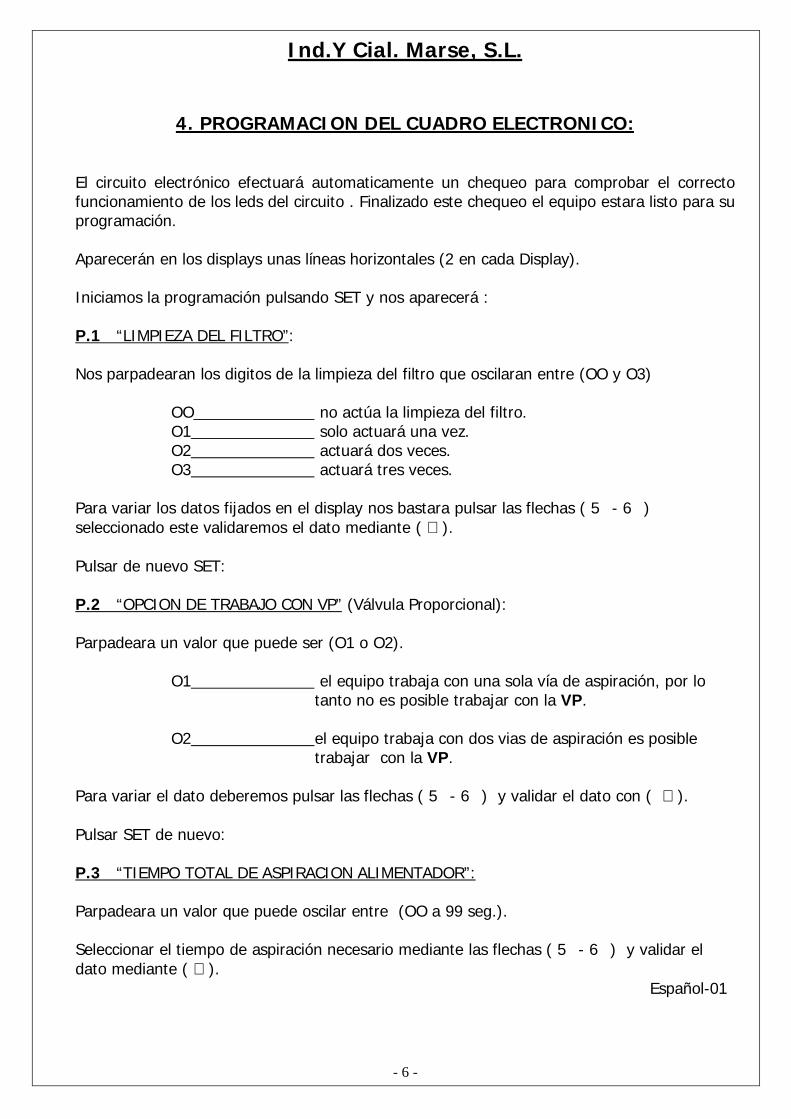
4. PROGRAMACION DEL CUADRO ELECTRONICO:
El circuito electrónico efectuará automaticamente un chequeo para comprobar el correctofuncionamiento de los leds del circuito . Finalizado este chequeo el equipo estara listo para suprogramación.
Aparecerán en los displays unas líneas horizontales (2 en cada Display).
Iniciamos la programación pulsando SET y nos aparecerá :
P.1 “LIMPIEZA DEL FILTRO”:
Nos parpadearan los digitos de la limpieza del filtro que oscilaran entre (OO y O3)
OO no actúa la limpieza del filtro.O1 solo actuará una vez.O2 actuará dos veces.O3 actuará tres veces.
Para variar los datos fijados en el display nos bastara pulsar las flechas ( 5 - 6 )seleccionado este validaremos el dato mediante ( ↵ ).
Pulsar de nuevo SET:
P.2 “OPCION DE TRABAJO CON VP” (Válvula Proporcional):
Parpadeara un valor que puede ser (O1 o O2).
O1 el equipo trabaja con una sola vía de aspiración, por lotanto no es posible trabajar con la VP.
O2 el equipo trabaja con dos vias de aspiración es posibletrabajar con la VP.
Para variar el dato deberemos pulsar las flechas ( 5 - 6 ) y validar el dato con ( ↵ ).
Pulsar SET de nuevo:
P.3 “TIEMPO TOTAL DE ASPIRACION ALIMENTADOR”:
Parpadeara un valor que puede oscilar entre (OO a 99 seg.).
Seleccionar el tiempo de aspiración necesario mediante las flechas ( 5 - 6 ) y validar eldato mediante ( ↵ ).
Español-01

Ind.Y Cial. Marse, S.L.
- 7 -
• Tener en cuenta que el valor imputado ha de ser igual o superior al valor de P4 o a lasuma de los valores imputados en P4+P5.
Pulse SET de nuevo:
P.4 “TIEMPO DE ASPIRACION VIA 1 V-1”:
1. En caso de haber seleccionado en P2 una sola vía (O1) ajustaremos en P4 elmismo tiempo que en P3 (OO a 99 seg.) mediante las flechas ( 5 - 6 ) y validarel valor mediante ( ↵ ).
NOTA: Es posible programar un valor inferior en P4 que en P3El equipo reiniciará la programación en P1 dando por finalizada la programación.
Proceder a la puesta en marcha del alimentador apretando la flecha ( ↵ ) y SET.
2. En caso de haber seleccionado en P2 (O2) ajustaremos en P4 el tiempo quecreamos necesario de aspiración en la vía 1, mediante las flechas ( 5 - 6 ) yvalidar el valor mediante ( ↵ ). Posteriormente ver punto P.5 del manual.
Pulsar SET de nuevo:
P.5 “TIEMPO DE ASPIRACION VIA 2 V-2”:
Este set solo nos aprecerá si en P2 lo programamos en O2 (2 vias de aspiración).
Ajustar el tiempo de aspiración de la vía 2 de (OO a 99 sg.) mediante las flechas ( 5 - 6 ) yvalidar el valor mediante ( ↵ ).
NOTA DE AVISO:El parametro P4 y P5 no pueden sobrepasar el tiempo de aspiración de P3.
Si es sobrepasado dicho tiempo nos aparecerá en el display el símbolo de “er”.
Ejemplo: no correcto correcto
P3=15 “. P3= 15 “.P4=09 “. P4= 10 “.P5=08 “. P5= 05 “.
P4+P5 ≤ P3 (la suma de P4 y P5 nunca deben superar a P3).
El equipo reiniciará la programación en P1 dando por finalizada la programación.
Proceder a la puesta en marcha del alimentador apretando ( ↵ ) y SET, simultáneamente.
Español-01

Ind.Y Cial. Marse, S.L.
- 8 -
5. POSIBLES AVERIAS Y ANOMALÍAS:
AVISOS YANOMALIAS
OBSERVACIONES REMEDIO
ST BY Dichas siglas aparecerán cuando elequipo haya cargado la tolva y latrampilla quede abierta o sujeta porel material
Cuando el material sea consumido porla máquina desaparecerá si no limpiarla trampilla de posibles granos dematerial.
FA AL Dichas siglas aparecerán cuando elequipo aspira en vacio 3 vecesindicando que no tenemos materiala cargar
Cargar de material su depósito paraaspirar y rearmar el equipo
Er Error al programar los tiempos deaspiración de P4 y P5
Reprogramar los tiempos de nuevoTeniendo en cuenta lo programado enP3
P Pasos a seguir de la programaciónP1, P2, P3 ,P4 y P5.
Modificar y memorizar los datosmediante( 5 - 6) ( ↵ )
Equipocorrectamenteconectado perono actuaningunafuncion
Trampilla de descarga obstruidaNo cierra correctamente dejando elciclo de trabajo abierto
Verificar por que causa la trampillaqueda abierta.Limpiar
No cargamaterial
Filtro obstruido o sucioMotor estropeado
Limpiar filtro o sustituirloLlamar al servicio técnico
Español-01
Ind.Y Cial. Marse, S.L.
- 9 -
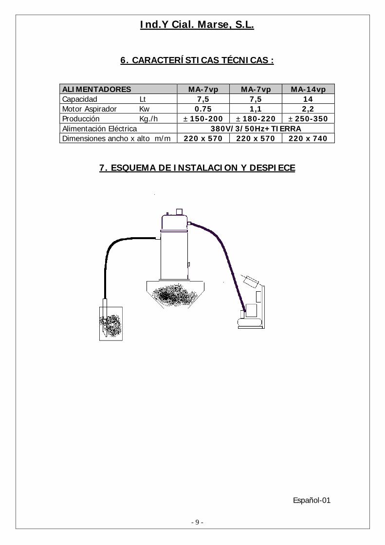
6. CARACTERÍSTICAS TÉCNICAS :
ALIMENTADORES MA-7vp MA-7vp MA-14vpCapacidad Lt 7,5 7,5 14Motor Aspirador Kw 0.75 1,1 2,2Producción Kg./h ± 150-200 ± 180-220 ± 250-350Alimentación Eléctrica 380V/3/50Hz+TIERRADimensiones ancho x alto m/m 220 x 570 220 x 570 220 x 740
7. ESQUEMA DE INSTALACION Y DESPIECE
Español-01

Ind.Y Cial. Marse, S.L.
- 10 -
8. SINOPTICO CUADRO ELECTRONICO
01 VALVULA DE LIMPIEZA
02 TIEMPO DE ASPIRACION A
03 TIEMPO DE ASPIRACION B
04 ALARMA
05 INTERRUPTOR PARO MARCHA
06 PULSADOR PARA PROGRAMACION
07 PULSADOR PARA SUBIR PARAMETROS
08 PULSADOR PARA BAJAR PARAMETROS
09 PULSADOR PARA MEMORIZAR PARAMETRO
10 DISPLAY DE PROGRAMACION
11 DISPLAY DE PARAMETROS
Español-01
SET 5 6 ↵ALARM
LOAD FROM B
LOAD FROM A
FILTER CLEANING
11
6
2
5
4
3
10
987
1

Ind.Y Cial. Marse, S.L.
- 11 -
S A T 6 3 4O O O O O OO O O O O O1 2 T 3 4 5
SENSOR
VALVULAPROPORCIONAL
ENTRADA DE CABLE TANDEN
CABLE SOPLADO
REGLETA DE CONEXION


Ind.Y Cial. Marse, S.L.
L1 L2 L3 NC A1
97 95 98 96
L1 L2 L3
MOTOR
CONTACTOR
RELE TERMICO
1 2 3 4 5 6 7 8 T
1 2 3 4 5 6 7 8 T
RO
JO
AZU
L
NEG
RO
VIO
LETA
MA
RR
ON
GR
IS
SON
DA
SEN
SOR
TIER
RA
BORNAS DE CONEXION
48 24 0TRANSFORMADOR
380 220 0
CABLE CONEXIÓN DEPÓSITO-CAJA 1 2 3 V.P.P 45
ALIMENTACIÓN
TierrL3L2L1
Ind.Y Cial. Marse, S.L.
9. GARANTIA:
-LA GARANTIA SERA DE 12 MESES FECHA FACTURA.
-LA GARANTIA INCLUYE PIEZAS Y MANO DE OBRA, SIEMPRE QUE SEA POR UN MALFUNCIONAMIENTO DEL EQUIPO, NUNCA POR UNA MALA UTILIZACIÓN DELUSUARIO.
PARA CUALQUIER CONSULTA LLAMAR AL SERVICIO TECNICO:
TEL: 0034-93-490.20.40
E-mail: [email protected]
Español-01
Ind.Y Cial. Marse, S.L.
- 15 -
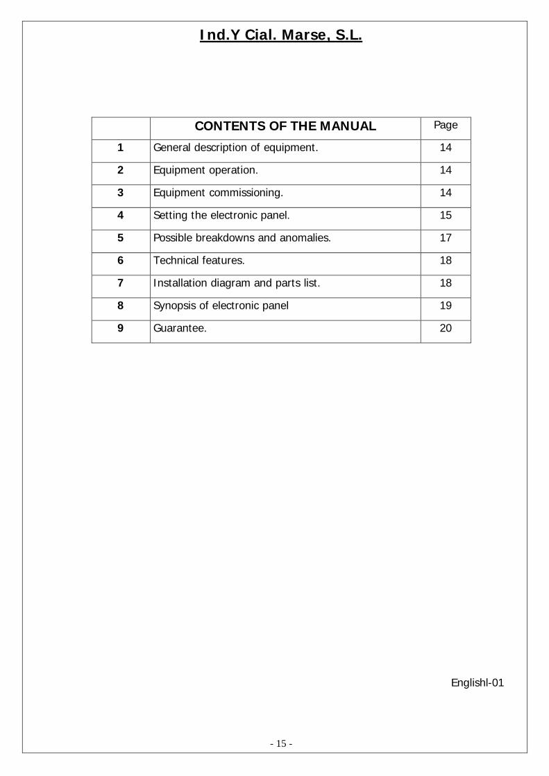
CONTENTS OF THE MANUAL Page
1 General description of equipment. 14
2 Equipment operation. 14
3 Equipment commissioning. 14
4 Setting the electronic panel. 15
5 Possible breakdowns and anomalies. 17
6 Technical features. 18
7 Installation diagram and parts list. 18
8 Synopsis of electronic panel 19
9 Guarantee. 20
Englishl-01

Ind.Y Cial. Marse, S.L.
- 16 -
1. GENERAL DESCRIPTION OF EQUIPMENT:
Manufactured in AISI-304 stainless steel for easy cleaning and longer life, with an electronicpanel allowing suction time to be regulated as required, maintaining a constant flow ofmaterial in the machine hopper, reducing the loading time and automating the feedingsystem of your industry.
The three-phase MAT-7vp /MAT-14vp vacuum loader comprises a suction pump, a filter,a tank or material collector, suction tube with its nozzle and electronic/magnetic operationcontrol.
2. EQUIPMENT OPERATION:
The motor sucks air from the tank, producing a vacuum inside same with respect to theatmospheric pressure, obtaining a suction flow in the tube placed in the plastic materialrecipient of the user, which is absorbed and left inside the vacuum loader.
When the set loading time has passed, the motor stops and the material is automaticallyplaced in the machine hopper. When all the material from the feeder tank has fallen into thehopper and the lower hatch returns to its initial position, the cycle is completed. This isrepeated until the machine hopper is full.
3. EQUIPMENT COMMISSIONING:
Position equipment on the hopper, securing the base with screws.
Connect the plastic tube to the feeder inlet, with the tube mesh in direct contact with thehousing, to reduce any static electricity produced by the material flow. Submerge thestainless steel nozzle inside the recipient where the material to be transported is stored.
Check that the filter is correctly fitted and close the upper cover of the accumulator tank.
Connect the power supply to the control panel using the sheathed cable supplied(380V/3/50Hz+Earth). Connect the switch (start-stop) located on the control panel.
Englishl-01

Ind.Y Cial. Marse, S.L.
- 17 -
4. SETTING THE ELECTRONIC PANEL:
The electronic circuit will automatically perform a test to check that the circuit LED’s functioncorrectly. After completing the test, the equipment is ready for setting it.
Horizontal lines (2 on each Display) will appear on the displays.
Setting is started by pressing SET, and the following message appears:
P.1 “FILTER CLEANING”
The digits of the filter cleaning flash between (00 and 03)
00______________ filter cleaning not in operation01______________ will only operate once02______________ will, operate twice03______________ will operate three times
In order to vary the data on the display, simply press the (5- 6) arrows. After selection,confirm by pressing (↵).
Press SET again:
P.2 “PV OPTION” (Proportional valve)
A setting will flash, which may be (01 or 02)
01 ________________ the equipment works with a single suction channel, so it is notpossible to work with the PV.
02 _______________ the equipment works with two suction channels, makingit possible to work with the PV.
To vary these settings, press the (5- 6) arrows and confirm with (↵)
Press SET again.
P.3 “TOTAL SUCTION TIME OF FEEDER”
A setting ranging between (00 and 99 sec.) flashes.
Select the necessary suction time using the (5- 6) arrows and confirm by pressing (↵).

Ind.Y Cial. Marse, S.L.
- 18 -
• Bear in mind that the setting has to be equal or greater than the setting of P4 or the sumof the settings made in P4+P5.
Press Set again.
P.4 “SUCTION TIME OF CHANNEL 1 V-1”
1. If a single channel (01) was selected in P2, in P4 the same time should be set as in P3(00 to 99 sec.) using the (5- 6) arrows and confirmed by pressing (↵).
NOTE: It is possible to select a lower setting in P4 than in P3.The equipment will reset the setting in P1 and setting is completed.
2. If (02) was selected in P2, we can regulate in P4 the suction time we think necessary inchannel 1, using the (5- 6) arrows, and confirming the setting by pressing (↵).
Press Set again.
P.5 “SUCTION TIME OF CHANNEL 2 V-2”
This setting will only appear if we set P2 to 02 (2 suction channels)
Adjust the suction time of channel 2 (00 to 99 sec.) using the (5- 6) arrows and confirmthe setting by pressing (↵).
WARNING:Parameters P4 and P5 cannot exceed the suction time set in P3.
If exceeded, the “er” symbol appears in the display.
Example: incorrect correctP3=15”. P3=15”.P4=09” P4=10”P5=08” P5=05”
P4+P5 < P3 (the sum of P4 and P5 must never exceed P3)
The equipment will restart setting in P1, as setting is completed.
Proceed with start-up of the feeder by pressing (↵). and SET.
Englishl-01

Ind.Y Cial. Marse, S.L.
- 19 -
5. POSSIBLE BREAKDOWNS AND ANOMALIES
WARNINGS &ANOMALIES
OBSERVATIONS SOLUTION
ST BY These letters appear whenthe equipment has loadedthe hopper and the hatchremains open, held open bythe material
When the material is used up bythe machine it should close; ifnot, clean any grains of materialfrom the hatch.
AL FA These letters appear whenthe equipment sucksunloaded three times,meaning that there is nomaterial to load
Load material in tank for suctionand reset equipment
Er Error when setting P4 and P5suction times
Re-set suction times, bearing inmind the setting selected in P3
P Setting steps to be followed:P1, P2, P3, P4 and P5
Change and save all data bymeans of (5- 6) (↵)
Equipment correctlyconnected but nofunctions areperformed
Unloading hatch blocked;does not close correctly sowork cycle is incomplete
Check why hatch remains openClean
No material loaded Filter blocked or dirtyMotor broken
Clean filter or replaceCall technical service
Englishl-01

Ind.Y Cial. Marse, S.L.
- 20 -
6. TECHNICAL FEATURES
VACUUM LOADER MA-7vp MA-7vp MA-14vpCapacity Lt 7,5 7,5 14Suction pump motor Kw 0.75 1,1 2.2Production kg/hr ± 150-200 ± 180-220 ± 250-350Electrical supply 380v/ 3Ph/ 50Hz+ EARTHDimensions width x height mm 220 x 570 220 x 570 220 x 740
7. INSTALLATION DIAGRAM AND PARTS LIST
Englishl-01
Ind.Y Cial. Marse, S.L.
- 21 -
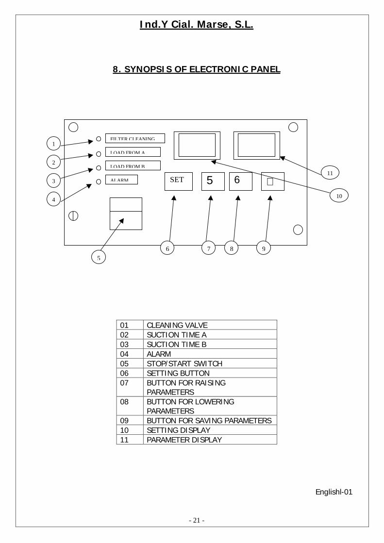
8. SYNOPSIS OF ELECTRONIC PANEL
01 CLEANING VALVE02 SUCTION TIME A03 SUCTION TIME B04 ALARM05 STOP/START SWITCH06 SETTING BUTTON07 BUTTON FOR RAISING
PARAMETERS08 BUTTON FOR LOWERING
PARAMETERS09 BUTTON FOR SAVING PARAMETERS10 SETTING DISPLAY11 PARAMETER DISPLAY
Englishl-01
SET 5 6 ↵ALARM
LOAD FROM B
LOAD FROM A
FILTER CLEANING
11
6
2
5
4
3
10
987
1

Ind.Y Cial. Marse, S.L.
- 22 -
Englishl-01
S A T 6 3 4O O O O O OO O O O O O1 2 T 3 4 5
SENSOR
PROPORTIONALVALVE
CABLE CONNECTION
BLOW CABLE
CONNECTIONS
Ind.Y Cial. Marse, S.L.
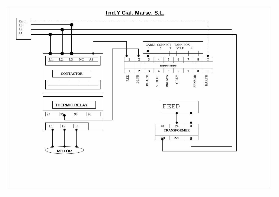
L1 L2 L3 NC A1
97 95 98 96
L1 L2 L3
MOTOR
CONTACTOR
THERMIC RELAY
1 2 3 4 5 6 7 8 T
1 2 3 4 5 6 7 8 T
RED
BLU
E
BLA
CK
VIO
LET
BR
OW
N
GR
EY
SEN
SOR
EAR
TH
CONNCTIONS
48 24 0TRANSFORMER
380 220 0
CABLE CONNECT TANK-BOX 1 2 3 V.P.P 45
FEED
EarthL3L2L1

Ind.Y Cial. Marse, S.L.
9. GUARANTEE
- The guarantee is valid for 12 months from the date of purchase.
- The guarantee covers parts and labour provided it is applied to a malfunction of theunit and not incorrect use.
For any queries please call our Customer Service Department:
Tel: 0034-93-490.20.40
E-mail:[email protected]
English-01
Ind.Y Cial. Marse, S.L.
- 25 -
TABLE DES MATIÈRES DU MANUEL Page
1 Description générale de l'appareil. 22
2 Fonctionnement de l'appareil 22
3 Mise en service de l'appareil 22
4 Programmation du tableau électronique 23
5 Pannes et anomalies éventuelles 25
6 Caractéristiques techniques 26
7 Schéma d'installation et vue eclatée 26
8 Schéma synoptique du tableau electronique 27
9 Garantie. 28
Français-01

Ind.Y Cial. Marse, S.L.
- 26 -
1. DESCRIPTION GÉNÉRALE DE L'APPAREIL:
Fabriqué en acier inoxydable AISI-304 pour un nettoyage facile et une longue durée, tableauélectronique permettant de régler selon vos besoins le temps d'aspiration, en maintenant unflux constant de matériau dans la trémie de la machine et en réduisant son temps dechargement grâce à l'automatisation du système d'alimentation de l'usine.
L'alimenteur triphasé MAT-7vp/ MAT-14vp comprend un moteur d'aspiration, un filtre, unréservoir ou accumulateur de matériau, une tuyauterie d'aspiration avec sa lance et uncontrôle électronique/magnétique de fonctionnement.
2. FONCTIONNEMENT DE L'APPAREIL:
Le moteur aspire l'air du réservoir et y provoque une dépression par rapport à la pressionatmosphérique, ce qui permet d'obtenir un flux d'aspiration par la tuyauterie déposée dans lerécipient de matière plastique de votre propriété, qui est absorbée et déposée à l'intérieur del'alimenteur.
Lorsque s'est écoulé le temps de chargement programmé, le moteur s'arrête et le matériause dépose automatiquement à l'intérieur de la trémie de la machine; lorsque tout le matériaudu réservoir de l'alimentateur sera tombé à l'intérieur de la trémie et que la trappe inférieurereviendra à sa position initiale, le cycle prendra fin. Il en sera de même jusqu'à ce que latrémie de la machine soit pleine.
3. MISE EN SERVICE DE L'APPAREIL:
Placer l'appareil sur la trémie en fixant la base à l'aide de vis.
Connecter la tuyauterie en plastique à l'entrée de l'alimenteur en laissant en contact directavec la carcasse de la gaine de la tuyauterie, afin de réduire l'électricité statique provoquéepar la circulation du matériau. Plonger la lance en inoxydable dans le récipient où est stockéle matériau à transporter.
Vérifier que le filtre est bien mis en place et fermer le couvercle supérieur du réservoird'accumulation.
Connecterr l'alimentation au tableau de contrôle grâce au câble à gaine livré(380V/3/50Hz+Terre) . Actionner l'interrupteur (marche-arrêt) placé sur le panneau decontrôle.
Français-01

Ind.Y Cial. Marse, S.L.
- 27 -
4. PROGRAMMATION DU TABLEAU ÉLECTRONIQUE:
Le circuit électronique procédera automatiquement à la vérification du bon fonctionnementdes leds du circuit. Lorsque cette vérification aura pris fin, l'appareil sera prêt à êtreprogrammé.
Des lignes horizontales apparaîtront sur les affichages (2 sur chaque affichage).
Commencer à programmer en appuyant sur SET et il apparaîtra:
P.1 “NETTOYAGE DU FILTRE”:
Les numéros du nettoyage du filtre qui oscilleront entre 00 et 03 clignoteront.
OO le nettoyage du filtre ne fonctionne pasO1 il ne fonctionnera qu'une foisO2 il fonctionnera deux foisO3 il fonctionnera trois fois
Pour modifier les données affichées, il suffira d'appuyer sur les flèches ( 5 - 6 ) Après cettesélection, valider la donnée grâce à ( ↵ ).
Appuyer à nouveau sur SET:
P.2 “OPTION DE FONCTIONNEMENT AVEC VP” (Vanne proportionnelle):
Une valeur qui peut être O1 ou O2 clignotera.
O1 l'appareil fonctionne avec une seule voie d'aspiration, il estpar conséquent impossible de travailler avec la VP
O2 l'appareil fonctionne avec deux voies d'aspiration, il estdonc possible de travailler avec la VP
Pour modifier la donnée, appuyer sur les flèches ( 5 - 6 ) et valider la donnée avec ( ↵ ).
Appuyer à nouveau sur SET:
P.3 “TEMPS TOTAL D'ASPIRATION ALIMENTEUR”:
Une valeur pouvant osciller entre 00 et 99 sec. clignotera.
Sélectionner le temps d'aspiration nécessaire à l'aide des flèches ( 5 - 6 ) et valider ladonnée grâce à ( ↵ ).

Ind.Y Cial. Marse, S.L.
- 28 -
• Tenir compte du fait que la valeur introduite doit être égale ou supérieure à la valeur deP4 ou à la somme des valeurs introduites en P4-P5.
Appuyer à nouveau sur SET:
P.4 “TEMPS D'ASPIRATION VOIE 1 V-1”:
3. Si on a sélectionné en P2 une seule voie (O1), régler en P4 le même temps qu'enP3 (OO à 99 sec.) à l'aide des flèches ( 5 - 6 ) et valider la valeur grâce à ( ↵).
NOTE: On peut programmer en P4 une valeur plus petite qu'en P3.L'appareil reprendra la programmation en P1, la programmation étant considéréeterminée.
Procéder à la mise en service de l'alimenteur en appuyant sur la flèche ( ↵ ) etSET.
4. Si on a sélectionné (02) en Pe, régler en P4 le temps d'aspiration que l'on estimenécessaire sur la voie 1, grâce aux flèches ( 5 - 6 ) et valider la valeur grâce à (↵). Voir ensuite le point P.5 du manuel.
Appuyer à nouveau sur SET:
P.5 “TEMPS D'ASPIRATION VOIE 2 V-2”:
Ce réglage n'apparaîtra en P2 que si on le programme en 02 (2 voies d'aspiration).Régler le temps d'aspiration de la voie 2 de (OO à 99 sec. à l'aide des flèches ( 5 - 6 ) etvalider la valeur grâce à ( ↵ ).
AVERTISSEMENT:Les paramètres P4 et P5 ne doivent pas dépasser le temps d'aspiration de P3.
Si ce temps est dépassé, il apparaîtra à l'écran le symbole “er”.
Exemple: incorrect correct
P3=15 “. P3= 15 “.P4=09 “. P4= 10 “.P5=08 “. P5= 05 “.
P4+P5 ≤ P3 (la somme de P4 et de P5 ne doit jamais dépasser P3).
L'appareil reprendra la programmation en P1 et la programmation sera considérée commeétant terminée.
Procéder à la mise en service de l'alimenteur en appuyant sur ( ↵ ) et SET simultanément.
Français-01

Ind.Y Cial. Marse, S.L.
- 29 -
5. PANNES ET ANOMALIES ÉVENTUELLES:
AVIS ETANOMALIES
OBSERVATIONS SOLUTION
ST BY Ces lettres apparaîtront lorsquel'appareil aura chargé la trémie etque la trappe restera ouverte oubloquée par le matériau
Lorsque le matériau aura étéconsommé par la machine, ces lettresdisparaîtront; sinon nettoyer la trappede tout grain de matériau éventuel
FA AL Ces lettres apparaîtront lorsquel'appareil aspirera à vide 3 fois,indiquant ainsi qu'il n'y a pas dematériau à charger
Charger le matériau dans le réservoirpour aspirer et réenclencher l'appareil
Er Erreur lors de la programmationdes temps d'aspiration de P4 et P5
Reprogrammer à nouveau les tempscompte tenu de la programmation deP3
P Etapes à suivre de laprogrammation P1, P2, P3 ,P4 etP5.
Modifier et mémoriser les donnéesgrâce à( 5 - 6) ( ↵ )
Equipementcorrectementconnecté maisaucunefonction nes'exécute
Trappe de déchargement bouchéeNe ferme pas bien et laisse le cyclede travail non terminé
Vérifier pour quelle raison la trappereste ouverteNettoyer
Ne charge pasde matériau
Filtre bouché ou saleMoteur endommagé
Nettoyer le filtre ou le remplacerAppeler le service technique
Français-01
Ind.Y Cial. Marse, S.L.
- 30 -
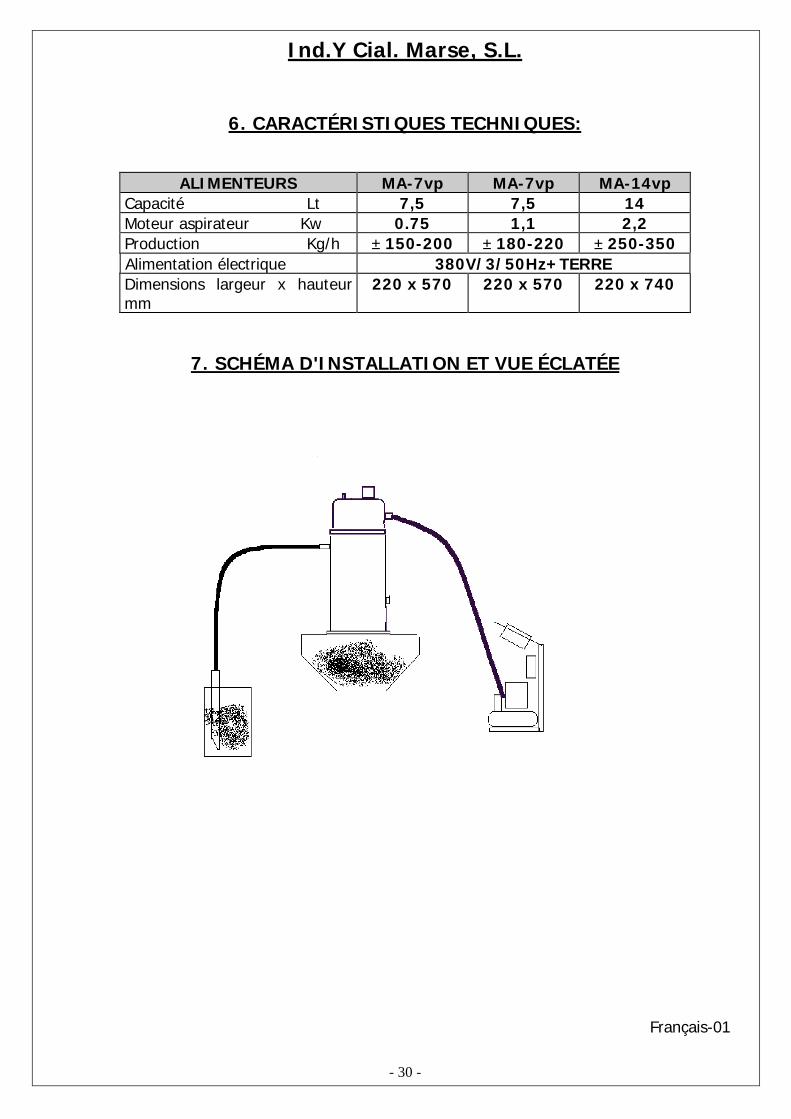
6. CARACTÉRISTIQUES TECHNIQUES:
ALIMENTEURS MA-7vp MA-7vp MA-14vpCapacité Lt 7,5 7,5 14Moteur aspirateur Kw 0.75 1,1 2,2Production Kg/h ± 150-200 ± 180-220 ± 250-350Alimentation électrique 380V/3/50Hz+TERREDimensions largeur x hauteurmm
220 x 570 220 x 570 220 x 740
7. SCHÉMA D'INSTALLATION ET VUE ÉCLATÉE
Français-01

Ind.Y Cial. Marse, S.L.
- 31 -
8. SCHÉMA SYNOPTIQUE DU TABLEAU ÉLECTRONIQUE
01 VANNE DE NETTOYAGE
02 TEMPS D'ASPIRATION A
03 TEMPS D'ASPIRATION B
04 ALARME
05 INTERRUPTEUR ARRÊT-MARCHE
06 POUSSOIR DE PROGRAMMATION
07 POUSSOIR AUGMENTATION PARAMÈTRES
08 POUSSOIR DIMINUTION PARAMÈTRES
09 POUSSOIR MÉMORISATION PARAMÈTRE
10 AFFICHAGE DE LA PROGRAMMATION
11 AFFICHAGE DES PARAMÈTRES
Français-01
SET 5 6 ↵
ALARM
LOAD FROM B
LOAD FROM A
FILTER CLEANING
11
6
2
5
4
3
10
987
1
Ind.Y Cial. Marse, S.L.
- 32 -
Français-01
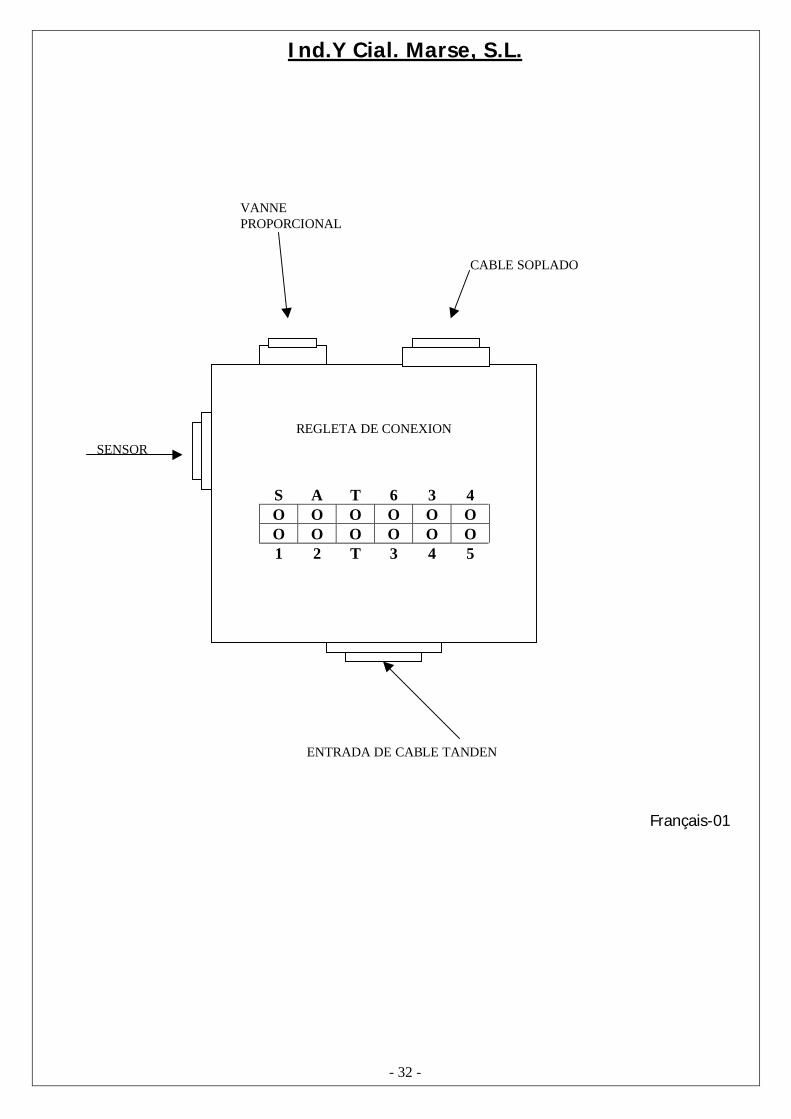
S A T 6 3 4O O O O O OO O O O O O1 2 T 3 4 5
SENSOR
VANNEPROPORCIONAL
ENTRADA DE CABLE TANDEN
CABLE SOPLADO
REGLETA DE CONEXION

Ind.Y Cial. Marse, S.L.
L1 L2 L3 NC A1
97 95 98 96
L1 L2 L3
MOTOR
CONTACTOR
RELE TERMICO
1 2 3 4 5 6 7 8 T
1 2 3 4 5 6 7 8 T
RO
JO
AZU
L
NEG
RO
VIO
LETA
MA
RR
ON
GR
IS
SON
DA
SEN
SOR
TIER
RA
BORNAS DE CONEXION
48 24 0TRANSFORMADOR
380 220 0
CABLE CONEXIÓN DEPÓSITO-CAJA 1 2 3 V.P.P 45
ALIMENTACIÓN
TierrL3L2L1

Ind.Y Cial. Marse, S.L.
9. GARANTIE:
- LA GARANTIE SERA DE 12 MOIS À COMPTER DE LA MISE EN MARCHE DEL’INSTALLATION.
- DURANT LES MOIS DE GARANTIE, SEULES LES PIÈCES DÉFECTUEUSES OU UNMAUVAIS FONCTIONNEMENT SERONT COUVERTS. NI LA MAIN D’CEUVRE, NI LESPIÉCES ENDOMMAGÉES PAR UNE MAUVAISE UTILISATION N’ENTRENT DANS CETTEGARANTIE.
POUR TOUT PROBLÈME TECHNIQUE, APPELER LE SERVICE TECHNIQUE:
TÉL: 0034- 93 490.20.40
E-mail: [email protected]
Français-01