Embed Size (px)
Citation preview
LRRIS InDUSTRIES Inc:.
ATV AND LIGHT UTILITY VEHICLE SERVICE MANUAL
Foreword
This manual is designed primarily for use by ATV service technicians in a properly equipped shop. Since a certain knowledge of mechanical theory, tool use, and shop procedures is necessary to perform the service work safely, all operations should be performed by qualified service personnel only. In order to perform the work efficiently and prevent costly errors, the technician should read the text and be familiar with procedures before starting the work. Cleanliness of parts and tools as well as the work area is of primary importance.
All references to left and right side of the vehicle are from the operator's perspective when seated in a normal riding position.
This manual includes procedures for maintenance operations, component identification and unit repair, along with service specifications for 1996-1998 model Polaris ATVs and Light Utility Vehicles. The section index tabs enable the user to quickly locate the section desired. In addition, a table of contents is placed at the beginning of each section for location of specific page numbers and service information. Keep this manual available for reference in the shop area.
To keep this manual current it is important that it is updated yearly with new model information and specifications.
At the time of publication all information contained in this manual was current. However, all materials and specifications are subject to change without notice.
Comments or suggestions about this manual may be directed to: Polaris Industries Inc., Service Publications Supervisor, 1225 Highway 169 North, Minneapolis, Minnesota 55441-5078.
1996-1998 Service Manual Volume II Part No. 9913680 1998 Service Manual Update Part No. 9914752
Printed in U.S.A.
UNDERSTANDING SAFETY LABELS AND INSTRUCTIONS
Throughout these instructions, important information is brought to your attention by the following symbols:
.&,.The Safety Alert Symbol means ATIENTIONI BECOME ALERTI YOUR SAFETY IS INVOLVED!
A DANGER
Failure to follow DANGER instructions will result in severe injury or death to the operator, passenger, bystander or person inspecting or servicing the ATV.
A WARNING
Failure to follow WARNING instructions could result in severe injury or death to the operator, passenger, bystander or person inspecting or servicing the ATV.
A CAUTION indicates special precautions that must be taken to avoid minor personal injury, or ATV or property damage.
NOTE:
A NOTE provides key information to clarify instructions.
Trademarks
Polaris acknowledges the following products mentioned in this manual:
FLEXLOC, Registered Trademark of SPS Technologies Loctite, Registered Trademark of the Loctite Corporation STA-BIL, Registered Trademark of Gold Eagle FOX, Registered Trademark of Fox Shox Nyogel, Trademark of Wm. F. Nye Co. Fluke, Registered Trademark of John Fluke Mfg. Co. Mity Vac, Registered Trademark of Neward Enterprises, Inc. Ammco, Registered Trademark of Ammco Tools, Inc. Torx, Registered Trademark of Textron Hilliard, Trademark of the Hilliard Corporation
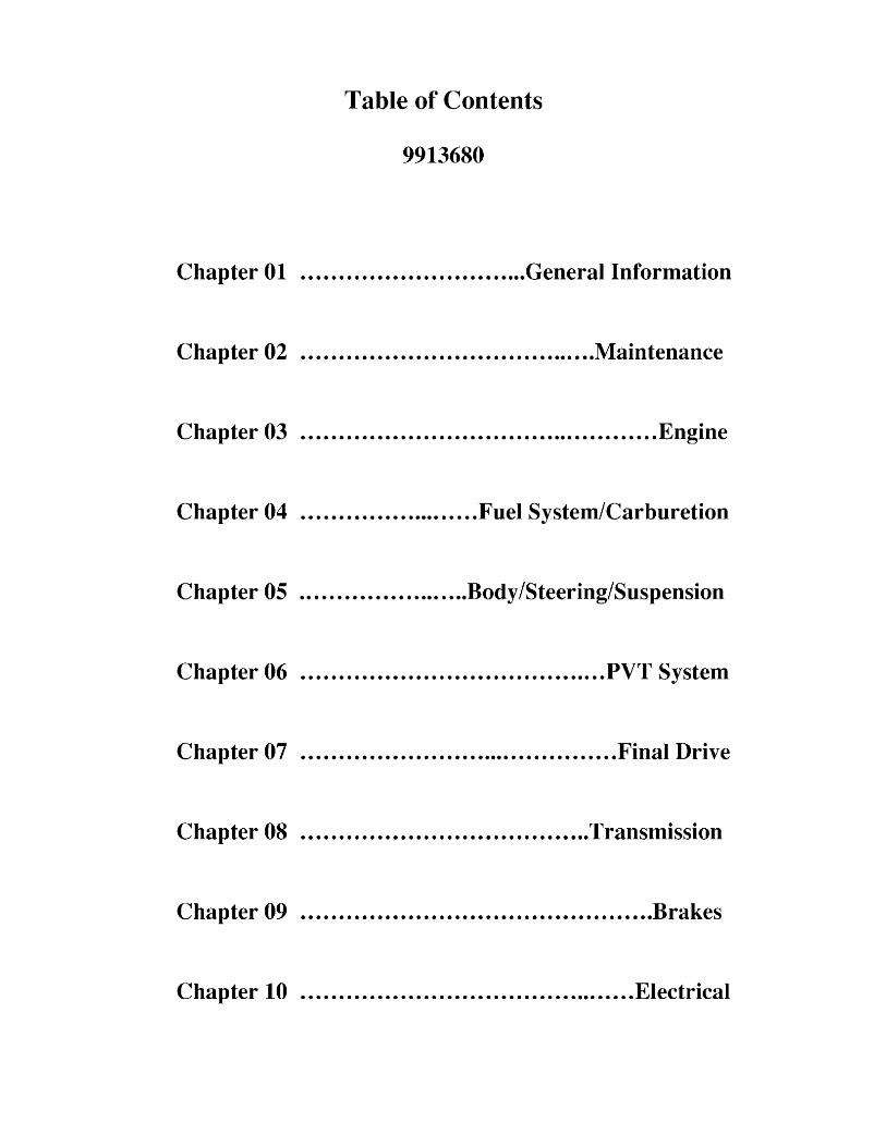
Table of Contents
9913680
Chapter 01 .............................. General Information
Chapter 02 ....................................... Maintenance
Chapter 03 ............................................... Engine
Chapter 04 ........................ Fuel System/Carburetion
Chapter 05 ....................... Body/Steering/Suspension
Chapter 06 ........................................ PVT System
Chapter 07 .......................................... Final Drive
Chapter 08 ...................................... Transmission
Chapter 09 .............................................. Brakes
Chapter 10 ............................................ Electrical

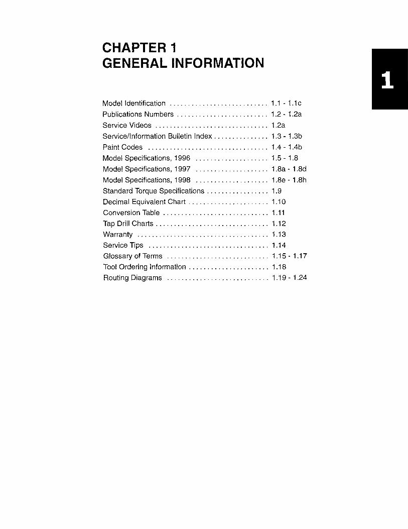
CHAPTER 1 GENERAL INFORMATION
Model Identification ........................... 1.1 - 1.1 c
Publications Numbers . . . . . . . . . . . . . . . . . . . . . . . .. 1.2 - 1.2a
Service Videos ............................... 1.2a
Service/Information Bulletin Index. . . . . . . . . . . . . .. 1.3 - 1.3b
Paint Codes ................................. 1.4 - 1.4b
Model Specifications, 1996 1.5 - 1.8
Model Specifications, 1997 .................... 1.8a - 1.8d
Model Specifications, 1998 .................... 1.8e - 1.8h
Standard Torque Specifications. . . . . . . . . . . . . . . .. 1.9
Decimal Equivalent Chart . . . . . . . . . . . . . . . . . . . . .. 1.10
Conversion Table . . . . . . . . . . . . . . . . . . . . . . . . . . . .. 1.11
Tap Drill Charts. . . . . . . . . . . . . . . . . . . . . . . . . . . . . .. 1.12
Warranty .................................... 1 .13
Service Tips ................................. 1.14
Glossary of Terms ............................ 1.15 - 1.17
Tool Ordering Information ..................... , 1.18
Routing Diagrams ............................ 1.19 - 1.24
GENERAL INFORMATION Model Identification
Engine Serial Number Location
Whenever corresponding about an engine, be sure to refer to the engine model number and serial number. This information can be found on the sticker applied to the manual starter recoil housing. An additional number is stamped in one of the following locations:
• 4 stroke models - center top of crankcase beneath the cylinder coolant elbow
• 2 stroke liquid cooled models - center top of crankcase beneath the carburetor mounting flange
• 2 stroke air cooled models - top of crankcase near right side of cylinder
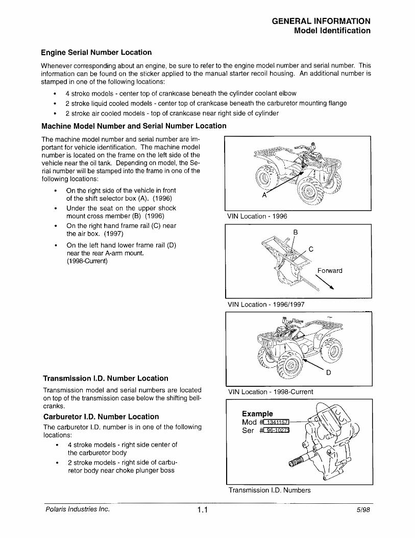
Machine Model Number and Serial Number Location
The machine model number and serial number are important for vehicle identification. The machine model number is located on the frame on the left side of the vehicle near the oil tank. Depending on model, the Serial number will be stamped into the frame in one of the following locations:
• On the right side of the vehicle in front of the shift selector box (A). (1996)
• Under the seat on the upper shock mount cross member (8) (1996)
• On the right hand frame rail (C) near the air box. (1997)
• On the left hand lower frame rail (D) near the rear A-arm mount. (199B-Current)
Transmission 1.0. Number Location
Transmission model and serial numbers are located on top of the transmission case below the shifting bellcranks.
Carburetor 1.0. Number Location The carburetor 1.0. number is in one of the following locations:
4 stroke models - right side center of the carburetor body
• 2 stroke models - right side of carburetor body near choke plunger boss
Polaris Industries Inc. 1.1
VIN Location - 1996
VIN Location - 1996/1997
VIN Location - 199B-Current
Example Mod :ffl 13411571
Ser #t 96-1Q273
Transmission 1.0. Numbers
5/98
GENERAL INFORMATION Model Identification
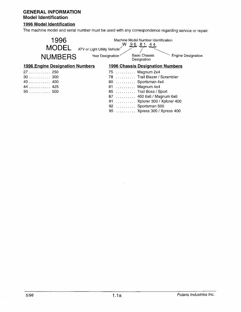
1996 Model Identification The machine model and serial number must be used with any correspondence regarding service or repair.
1996 Machine Model Number Identification W 96 81
MOD EL ATV or Light Utility vehicle/- T -i~ N U M B E R S Year Designation Basic Chassis Engine Designation
Designation
1996 Engine Designation Numbers 1996 Chassis Designation Numbers 27 ........... 250 75 .......... Magnum 2x4 30 ........... 300 78 .......... Trail Blazer / Scrambler 40 ........... 400 80 .......... Sportsman 4x4 44 ........... 425 81 .......... Magnum 4x4 50 ........... 500 85 .......... Trail Boss / Sport
87 .......... 400 6x6 / Magnum 6x6 91 .......... Xplorer 300 / Xplorer 400 92 .......... Sportsman 500 95 .......... Xpress 300 / Xpress 400
5/98 1.1 a Polaris Industries Inc.
GENERAL INFORMATION Model Identification
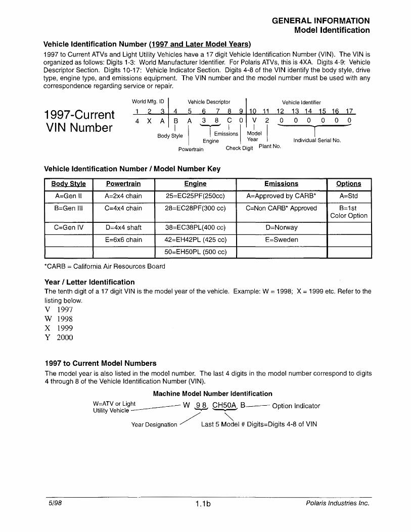
Vehicle Identification Number (1997 and Later Model Years) 1997 to Current ATVs and Light Utility Vehicles have a 17 digit Vehicle Identification Number (VIN). The VIN is organized as follows: Digits 1·3: World Manufacturer Identifier. For Polaris ATVs, this is 4XA Digits 4-9: Vehicle Descriptor Section. Digits 10-17: Vehicle Indicator Section. Digits 4-8 of the VIN identify the body style, drive type, engine type, and emissions equipment. The VIN number and the model number must be used with any correspondence regarding service or repair.
World Mfg. ID Vehicle Descriptor Vehicle Identifier
1997-Current 2 3 4 5 6 7 8 9 10 11 12 13 14 15 16 17
4 X A B A 3 8 C 0 V 2 0 0 0 0 0 0
VIN Number I ...
T ,;
I Emissions Body Style
I ~II
Engine MJdel I Year Individual Serial No.
Powertrain Check Digit Plant No.
Vehicle Identification Number I Model Number Key
Body Style Powertrain Engine Emissions Ogtions
A=Gen II A=2x4 chain 25:::EC25PF(250cc) A=Approved by CARB* A=Std
B=Gen III C=4x4 chain 28=EC28PF(300 cc) C=Non CARB* Approved B=1st Color Option
C=Gen IV D=4x4 shaft 38=EC38PL(400 cc) D=Norway
E=6x6 chain 42=EH42PL (425 cc) E=Sweden
50=EH50PL (500 cc)
*CARB = California Air Resources Board
Year I Letter Identification The tenth digit of a 17 digit VIN is the model year of the vehicle. Example: W = 1998; X = 1999 etc. Refer to the
listing below.
V 1997 W 1998 X 1999 Y 2000
1997 to Current Model Numbers The model year is also listed in the model number. The last 4 digits in the model number correspond to digits 4 through 8 of the Vehicle Identification Number (VIN).
Machine Model Number Identification
W;:;;ATV or Light ___ W 9 8 CH50A B Option Indicator Utility Vehicle --- ~' .. .
Year Designation ./ Last 5 M~el # Digits=Digits 4-8 of VIN
5/98 1.1 b Polaris Industries Inc.
GENERAL INFORMATION
5/98 1.1 c Polaris Industries Inc.
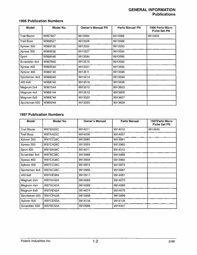
1996 Publication Numbers
Model Model No.
Trail Blazer W967827
Trail Boss W968527
Xplorer 300 W969130
Xpress 300 W969530
Sport W968540
Scrambler 4x4 W967840
Xpress 400 W969540
Xplorer 400 W969140
Sportsman 4x4 W968040
4006x6 W968740
Magnum 2x4 W967544
Magnum 4x4 W968144
Magnum 6x6 W968744
Sportsman 500 W969244
1997 Publication Numbers
Model Model No.
Trail Blazer W97BA25C
Trail Boss W97AA25C
Xplorer 300 W97CC28C
Xpress 300 W97CA28C
Sport 400 W97BA38C
Scrambler 4x4 W97BC38C
Xpress 400 W97CA38C
Xplorer 400 W97CC38C
Sportsman 4x4 W97AC38C
4006x6 W97AE38A
Magnum 2x4 W97AA42A
Magnum 4x4 W97AC42A
Magnum 6x6 W97AE42A
Sportsman 500 W97CH50A
Xplorer 500 W97CD50A
Scrambler 500 W97BC50A
Polaris Industries Inc.
Owner's Manual PN
9913584
9913506
9913332
9913327
9913584
9913519
9913327
9913511
9913414
9913516
9913512
9913512
9913522
9913269
Owner's Manual
9914011
9914056
9913980
9913959
9914011
9913988
9913959
9913974
9913966
9913917
9914069
9914069
9914074
9913998
9914134
9913988
1.2
GENERAL INFORMATION Publications
Parts Manual PN 1996 Parts Micro Fiche Set PN
9913586 9913433
9913588
9913590
9913592
9913586
9913582
9913592
9913598
9913594
9913596
9913603
9913605
9913607
9913609
Parts Manual , 997Parts Micro Fiche Set PN
9914012 9914645
9914057
9913981
9913960
9914012
9913989
9913960
9913975
9913967
9914081
9914070
9914083
9914075
9913999
9914135
9914307
5/98
GENERAL INFORMATION Publications
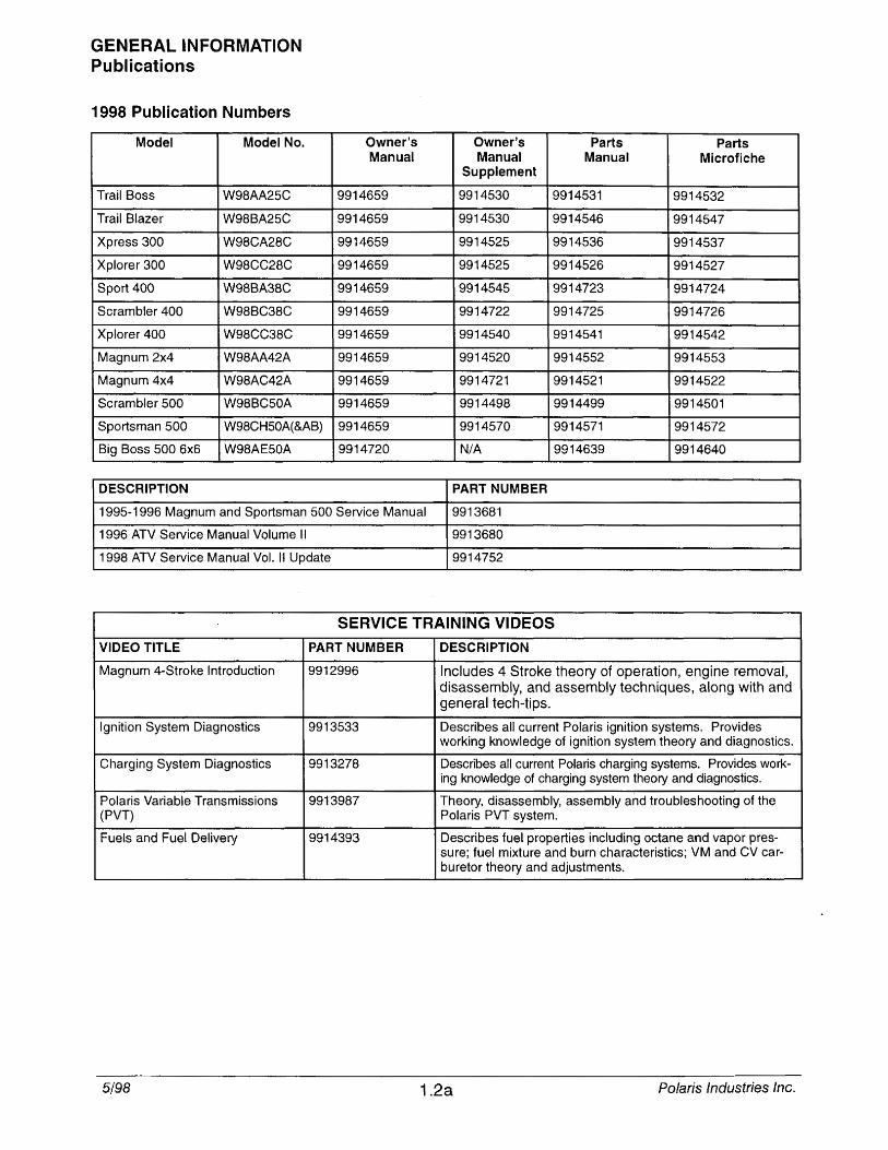
1998 Publication Numbers
Model Model No.
Trail Boss W98AA25C
Trail Blazer W98BA25C
Xpress 300 W98CA28C
Xplorer 300 W98CC28C
Sport 400 W98BA38C
Scrambler 400 W98BC38C
Xplorer 400 W98CC38C
Magnum 2x4 W98AA42A
Magnum 4x4 W98AC42A
Scrambler 500 W98BC50A
Sportsman 500 W98CH50A(&AB)
Big Boss 500 6x6 W98AE50A
DESCRIPTION
Owner's Manual
9914659
9914659
9914659
9914659
9914659
9914659
9914659
9914659
9914659
9914659
9914659
9914720
1995-1996 Magnum and Sportsman 500 Service Manual
1996 ATV Service Manual Volume II
1998 ATV Service Manual Vol. II Update
Owner's Parts Parts Manual Manual Microfiche
Supplement
9914530 9914531 9914532
9914530 9914546 9914547
9914525 9914536 9914537
9914525 9914526 9914527
9914545 9914723 9914724
9914722 9914725 9914726
9914540 9914541 9914542
9914520 9914552 9914553
9914721 9914521 9914522
9914498 9914499 9914501
9914570 9914571 9914572
N/A 9914639 9914640
PART NUMBER
9913681
9913680
9914752
SERVICE TRAINING VIDEOS
VIDEO TITLE PART NUMBER DESCRIPTION
Magnum 4-Stroke Introduction 9912996 Includes 4 Stroke theory of operation, engine removal, disassembly, and assembly techniques, along with and general tech-tips.
Ignition System Diagnostics 9913533 Describes all current Polaris ignition systems. Provides working knowledge of ignition system theory and diagnostics.
Charging System Diagnostics 9913278 Describes all current Polaris charging systems. Provides work-ing knowledge of charging system theory and diagnostics.
Polaris Variable Transmissions 9913987 Theory, disassembly, assembly and troubleshooting of the (PVT) Polaris PVT system.
Fuels and Fuel Delivery 9914393 Describes fuel properties including octane and vapor pres-sure; fuel mixture and burn characteristics; VM and CV car-buretor theory and adjustments.
5/98 1.2a Polaris Industries Inc.
GENERAL INFORMATION Service Bulletin Index
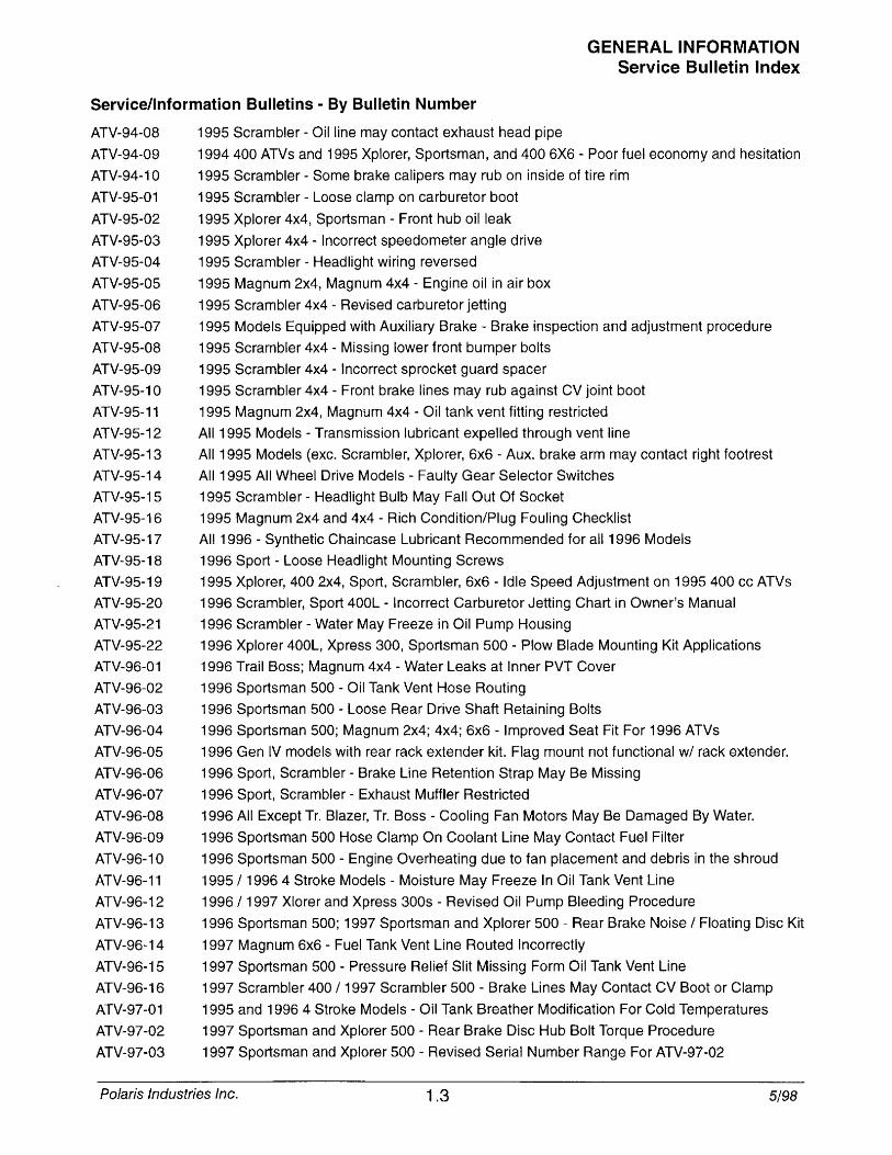
Service/Information Bulletins - By Bulletin Number
ATV-94-0B 1995 Scrambler - Oil line may contact exhaust head pipe
ATV-94-09 1994400 ATVs and 1995 Xplorer, Sportsman, and 400 6X6 - Poor fuel economy and hesitation
ATV-94-10
ATV-95-01
ATV-95-02
ATV-95-03
ATV-95-04
ATV-95-05
ATV-95-06
ATV-95-07
ATV-95-0B
ATV-95-09
ATV-95-10
ATV-95-11
ATV-95-12
ATV-95-13
ATV-95-14
ATV-95-15
ATV-95-16
ATV-95-17
ATV-95-1B
ATV-95-19
ATV-95-20
ATV-95-21
ATV-95-22
ATV-96-01
ATV-96-02
ATV-96-03
ATV-96-04
ATV-96-05
ATV-96-06
ATV-96-07
ATV-96-0B
ATV-96-09
ATV-96-10
ATV-96-11
ATV-96-12
ATV-96-13
ATV-96-14
ATV-96-15
ATV-96-16
ATV-97-01
ATV-97-02
ATV-97-03
1995 Scrambler - Some brake calipers may rub on inside of tire rim
1995 Scrambler - Loose clamp on carburetor boot
1995 Xplorer 4x4, Sportsman - Front hub oil leak
1995 Xplorer 4x4 - Incorrect speedometer angle drive
1995 Scrambler - Headlight wiring reversed
1995 Magnum 2x4, Magnum 4x4 - Engine oil in air box
1995 Scrambler 4x4 - Revised carburetor jetting
1995 Models Equipped with Auxiliary Brake - Brake inspection and adjustment procedure
1995 Scrambler 4x4 - Missing lower front bumper bolts
1995 Scrambler 4x4 - Incorrect sprocket guard spacer
1995 Scrambler 4x4 - Front brake lines may rub against CV joint boot
1995 Magnum 2x4, Magnum 4x4 - Oil tank vent fitting restricted
All 1995 Models - Transmission lubricant expelled through vent line
All 1995 Models (exc. Scrambler, Xplorer, 6x6 - Aux. brake arm may contact right footrest
All 1995 All Wheel Drive Models - Faulty Gear Selector Switches
1995 Scrambler - Headlight Bulb May Fall Out Of Socket
1995 Magnum 2x4 and 4x4 - Rich Condition/Plug Fouling Checklist
AI! 1996 - Synthetic Chaincase Lubricant Recommended for all 1996 Models
1996 Sport - Loose Headlight Mounting Screws
1995 Xplorer, 400 2x4, Sport, Scrambler, 6x6 - Idle Speed Adjustment on 1995400 cc ATVs
1996 Scrambler, Sport 400L - Incorrect Carburetor Jetting Chart in Owner's Manual
1996 Scrambler - Water May Freeze in Oil Pump Housing
1996 Xplorer 400L, Xpress 300, Sportsman 500 - Plow Blade Mounting Kit Applications
1996 Trail Boss; Magnum 4x4 - Water Leaks at Inner PVT Cover
1996 Sportsman 500 - Oil Tank Vent Hose Routing
1996 Sportsman 500 - Loose Rear Drive Shaft Retaining Bolts
1996 Sportsman 500; Magnum 2x4; 4x4; 6x6 - Improved Seat Fit For 1996 ATVs
1996 Gen IV models with rear rack extender kit. Flag mount not functional w/ rack extender.
1996 Sport, Scrambler - Brake Line Retention Strap May Be Missing
1996 Sport, Scrambler - Exhaust Muffler Restricted
1996 All Except Tr. Blazer, Tr. Boss - Cooling Fan Motors May Be Damaged By Water.
1996 Sportsman 500 Hose Clamp On Coolant Line May Contact Fuel Filter
1996 Sportsman 500 - Engine Overheating due to fan placement and debris in the shroud
1995/ 19964 Stroke Models Moisture May Freeze In Oil Tank Vent Line
1996/1997 Xlorer and Xpress 300s - Revised Oil Pump Bleeding Procedure
1996 Sportsman 500; 1997 Sportsman and Xplorer 500 - Rear Brake Noise / Floating Disc Kit
1997 Magnum 6x6 - Fuel Tank Vent Line Routed Incorrectly
1997 Sportsman 500 - Pressure Relief Slit Missing Form Oil Tank Vent Line
1997 Scrambler 400 / 1997 Scrambler 500 - Brake Lines May Contact CV Boot or Clamp
1995 and 19964 Stroke Models - Oil Tank Breather Modification For Cold Temperatures
1997 Sportsman and Xplorer 500 - Rear Brake Disc Hub Bolt Torque Procedure
1997 Sportsman and Xplorer 500 Revised Serial Number Range For ATV-97-02
Polaris Industries Inc. 1.3 5/98
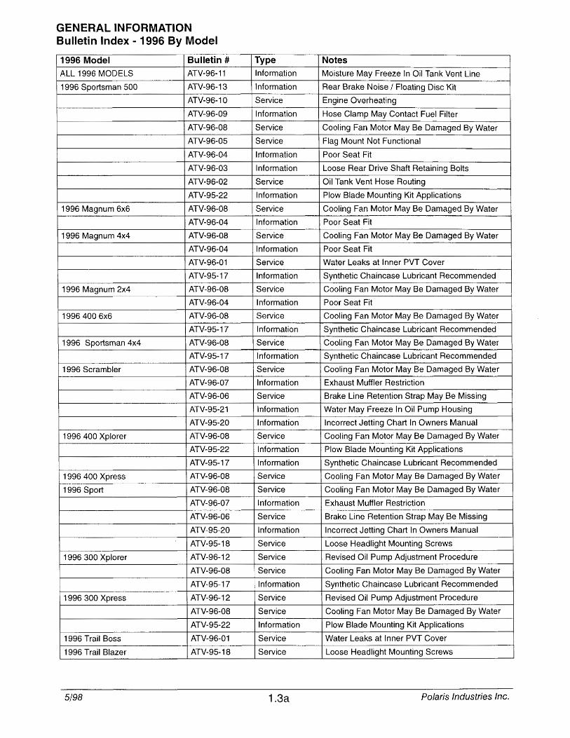
GENERAL INFORMATION Bulletin Index - 1996 By Model
1996 Model Bulletin #
ALL 1996 MODELS ATV-96-11
1996 Sportsman SOO ATV-96-13
ATV-96-10
ATV-96-09
ATV-96-0B
ATV-96-05
ATV-96-04
ATV-96-03
ATV-96-02
ATV-9S-22
1996 Magnum 6x6 ATV-96-0B
ATV-96-04
1996 Magnum 4x4 ATV-96-0B
ATV-96-04
ATV-96-01
ATV-9S-17
1996 Magnum 2x4 ATV-96-0B
ATV-96-04
19964006x6 ATV-96-0B
ATV-95-17
1996 Sportsman 4x4 ATV-96-0B
ATV-9S-17
1996 Scrambler ATV-96-0B
ATV-96-07
ATV-96-06
ATV-9S-21
ATV-95-20
1996400 Xplorer ATV-96-0B
ATV-9S-22
ATV-95-17
1996 400 Xpress ATV-96-0B
1996 Sport ATV-96-0B
ATV-96-07
ATV-96-06
ATV-9S-20
ATV-9S-1B
1996300 Xplorer ATV-96-12
ATV-96-0B
ATV-9S-17
1996 300 Xpress ATV-96-12
ATV-96-0B
ATV-9S-22
1996 Trail Boss ATV-96-01
1996 Trail Blazer ATV-9S-1B
5/98
Type Notes Information Moisture May Freeze In Oil Tank Vent Line
Information Rear Brake Noise / Floating Disc Kit
Service Engine Overheating
Information Hose Clamp May Contact Fuel Filter
Service Cooling Fan Motor May Be Damaged By Water
Service Flag Mount Not Functional
Information Poor Seat Fit
Information Loose Rear Drive Shaft Retaining Bolts
Service Oil Tank Vent Hose Routing
Information Plow Blade Mounting Kit Applications
Service Cooling Fan Motor May Be Damaged By Water
Information Poor Seat Fit
Service Cooling Fan Motor May Be Damaged By Water
Information Poor Seat Fit
Service Water Leaks at Inner PVT Cover
Information Synthetic Chaincase Lubricant Recommended
Service Cooling Fan Motor May Be Damaged By Water
Information Poor Seat Fit
Service Cooling Fan Motor May Be Damaged By Water
Information Synthetic Chaincase Lubricant Recommended
Service Cooling Fan Motor May Be Damaged By Water
Information Synthetic Chaincase Lubricant Recommended
Service Cooling Fan Motor May Be Damaged By Water
Information Exhaust Muffler Restriction
Service Brake Une Retention Strap May Be Missing
Information Water May Freeze In Oil Pump Housing
Information Incorrect Jetting Chart In Owners Manual
Service Cooling Fan Motor May Be Damaged By Water
Information Plow Blade Mounting Kit Applications
Information Synthetic Chaincase Lubricant Recommended
Service Cooling Fan Motor May Be Damaged By Water
Service Cooling Fan Motor May Be Damaged By Water
Information Exhaust Muffler Restriction
Service Brake Line Retention Strap May Be Missing
Information Incorrect Jetting Chart In Owners Manual
Service Loose Headlight Mounting Screws
Service Revised Oil Pump Adjustment Procedure
Service Cooling Fan Motor May Be Damaged By Water
Information Synthetic Chaincase Lubricant Recommended
Service Revised Oil Pump Adjustment Procedure
Service Cooling Fan Motor May Be Damaged By Water
Information Plow Blade Mounting Kit Applications
Service Water Leaks at Inner PVT Cover
Service Loose Headlight Mounting Screws
1.3a Polaris Industries Inc.
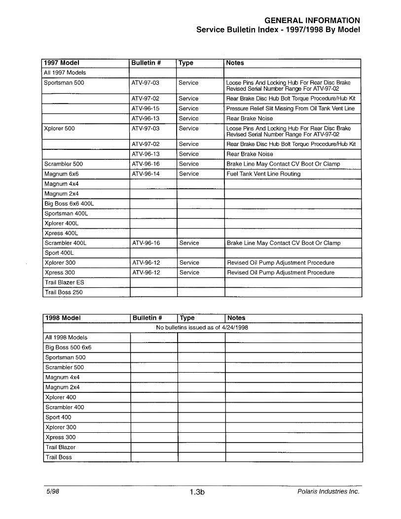
1997 Model
All 1997 Models
Sportsman 500
Xplorer 500
Scrambler 500
Magnum 6x6
Magnum 4x4
Magnum 2x4
Big Boss 6x6 400L
Sportsman 400L
Xplorer 400L
Xpress 400L
Scrambler 400L
Sport 400L
Xplorer 300
Xpress 300
Trail Blazer ES
Trail Boss 250
1998 Model
All 1998 Models
Big Boss 500 6x6
Sportsman 500
Scrambler 500
Magnum 4x4
Magnum 2x4
Xplorer 400
Scrambler 400
Sport 400
Xplorer 300
Xpress 300
Trail Blazer
Trail Boss
5/98
Bulletin #
ATV-97-03
ATV-97-02
ATV-96-15
ATV-96-13
ATV-97-03
ATV-97-02
ATV-96-13
ATV-96-16
ATV-96-14
ATV-96-16
ATV-96-12
ATV-96-12
Bulletin #
GENERAL INFORMATION Service Bulletin Index - 1997/1998 By Model
Type Notes
Service Loose Pins And Locking Hub For Rear Disc Brake Revised Serial Number Range For ATV-97-02
Service Rear Brake Disc Hub Bolt Torque Procedure/Hub Kit
Service Pressure Relief Slit Missing From Oil Tank Vent Line
Service Rear Brake Noise
Service Loose Pins And Locking Hub For Rear Disc Brake Revised Serial Number Range For ATV-97-02
Service Rear Brake Disc Hub Bolt Torque Procedure/Hub Kit
Service Rear Brake Noise
Service Brake Line May Contact CV Boot Or Clamp
Service Fuel Tank Vent Line Routing
Service Brake Line May Contact CV Boot Or Clamp
Service Revised Oil Pump Adjustment Procedure
Service Revised Oil Pump Adjustment Procedure
Type Notes
No bulletins issued as of 4/24/1998
1.3b Polaris Industries Inc.
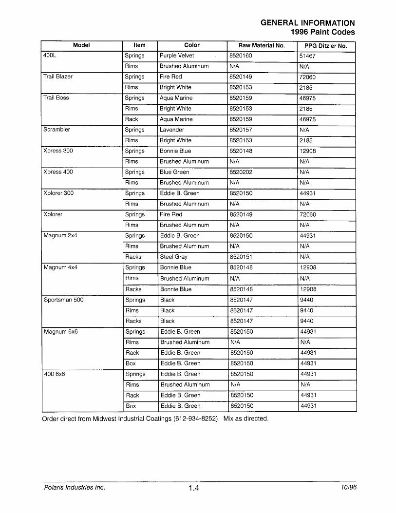
Model Item Color
400L Springs Purple Velvet
Rims Brushed Aluminum
Trail Blazer Springs Fire Red
Rims Bright White
Trail Boss Springs Aqua Marine
Rims Bright White
Rack Aqua Marine
Scrambler Springs Lavender
Rims Bright White
Xpress 300 Springs Bonnie Blue
Rims Brushed Aluminum
Xpress 400 Springs Blue Green
Rims Brushed Aluminum
Xplorer 300 Springs Eddie B. Green
Rims Brushed Aluminum
Xplorer Springs Fire Red
Rims Brushed Aluminum
Magnum 2x4 Springs Eddie B. Green
Rims Brushed Aluminum
Racks Steel Gray
Magnum 4x4 Springs Bonnie Blue
Rims Brushed Aluminum
Racks Bonnie Blue
Sportsman 500 Springs Black
Rims Black
Racks Black
Magnum 6x6 Springs Eddie B. Green
Rims Brushed Aluminum
Rack Eddie B. Green
Box Eddie B. Green
4006x6 Springs Eddie B. Green
Rims Brushed Aluminum
Rack Eddie B. Green
Box Eddie B. Green
GENERAL INFORMATION 1996 Pai nt Codes
Raw Material No. PPG Ditzler No.
8520160 51467
N/A N/A
8520149 72060
8520153 2185
8520159 46975
8520153 2185
8520159 46975
8520157 N/A
8520153 2185
8520148 12908
N/A N/A
8520202 N/A
N/A N/A
8520150 44931
N/A N/A
8520149 72060
N/A N/A
8520150 44931
N/A N/A
8520151 N/A
8520148 12908
N/A N/A
8520148 12908
8520147 9440
8520147 9440
8520147 9440
8520150 44931
N/A N/A
8520150 44931
8520150 44931
8520150 44931
N/A N/A
8520150 44931
8520150 44931
Order direct from Midwest Industrial Coatings (612-934-8252). Mix as directed.
Polaris Industries Inc. 1.4 10/96
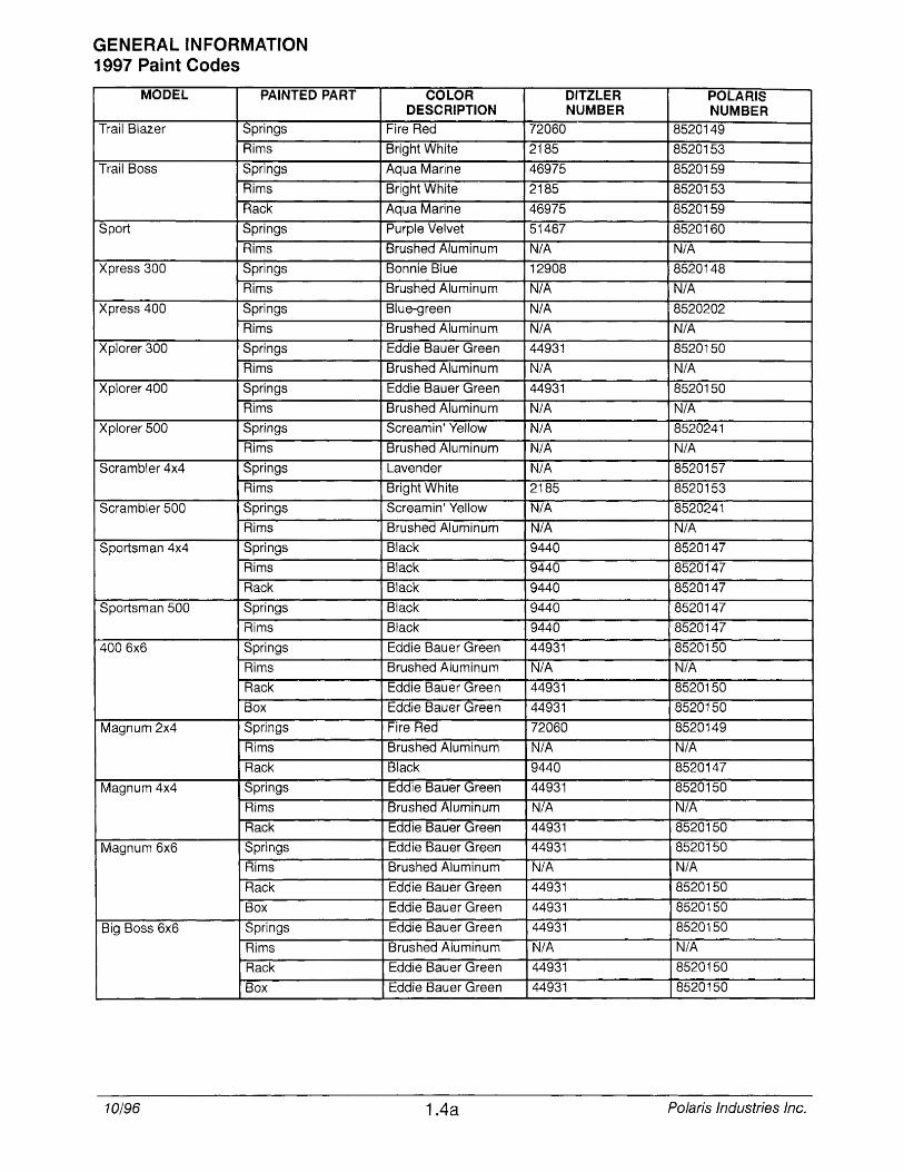
GENERAL INFORMATION 1997 Paint Codes
MODEL PAINTED PART
Trail Blazer Springs
Rims
Trail Boss Springs
Rims
Rack
Sport Springs
Rims
Xpress 300 Springs
Rims
Xpress 400 Springs
Rims
Xplorer 300 Springs
Rims
Xplorer 400 Springs
Rims
Xplorer 500 Springs
Rims
Scrambler 4x4 Springs
Rims
Scrambler 500 Springs
Rims
Sportsman 4x4 Springs
Rims
Rack
Sportsman 500 Springs
Rims
4006x6 Springs
Rims
Rack
Box
Magnum 2x4 Springs
Rims
Rack
Magnum 4x4 Springs
Rims
Rack
Magnum 6x6 Springs
Rims
Rack
Box
Big Boss 6x6 Springs
Rims
Rack
Box
10/96
COLOR DESCRIPTION
Fire Red
Bright White
Aqua Marine
Bright White
Aqua Marine
Purple Velvet
Brushed Aluminum
Bonnie Blue
Brushed Aluminum
Blue-green
Brushed Aluminum
Eddie Bauer Green
Brushed Aluminum
Eddie Bauer Green
Brushed Aluminum
Screamin' Yellow
Brushed Aluminum
Lavender
Bright White
Screamin' Yellow
Brushed Aluminum
Black
Black
Black
Black
Black
Eddie Bauer Green
Brushed Aluminum
Eddie Bauer Green
Eddie Bauer Green
Fire Red
Brushed Aluminum
Black
Eddie Bauer Green
Brushed Aluminum
Eddie Bauer Green
Eddie Bauer Green
Brushed Aluminum
Eddie Bauer Green
Eddie Bauer Green
Eddie Bauer Green
Brushed Aluminum
Eddie Bauer Green
Eddie Bauer Green
1.4a
DITZLER POLARIS NUMBER NUMBER
72060 8520149
2185 8520153
46975 8520159
2185 8520153
46975 8520159
51467 8520160
N/A N/A 12908 8520148
N/A N/A N/A 8520202
N/A N/A 44931 8520150
N/A N/A 44931 8520150
N/A N/A N/A 8520241
N/A N/A N/A 8520157
2185 8520153
N/A 8520241
N/A N/A 9440 8520147
9440 8520147
9440 8520147
9440 8520147
9440 8520147
44931 8520150
N/A N/A 44931 8520150
44931 8520150
72060 8520149
N/A N/A 9440 8520147
44931 8520150
N/A N/A 44931 8520150
44931 8520150
N/A N/A 44931 8520150
44931 8520150
44931 8520150
N/A N/A 44931 8520150
44931 8520150
Polaris Industries Inc.
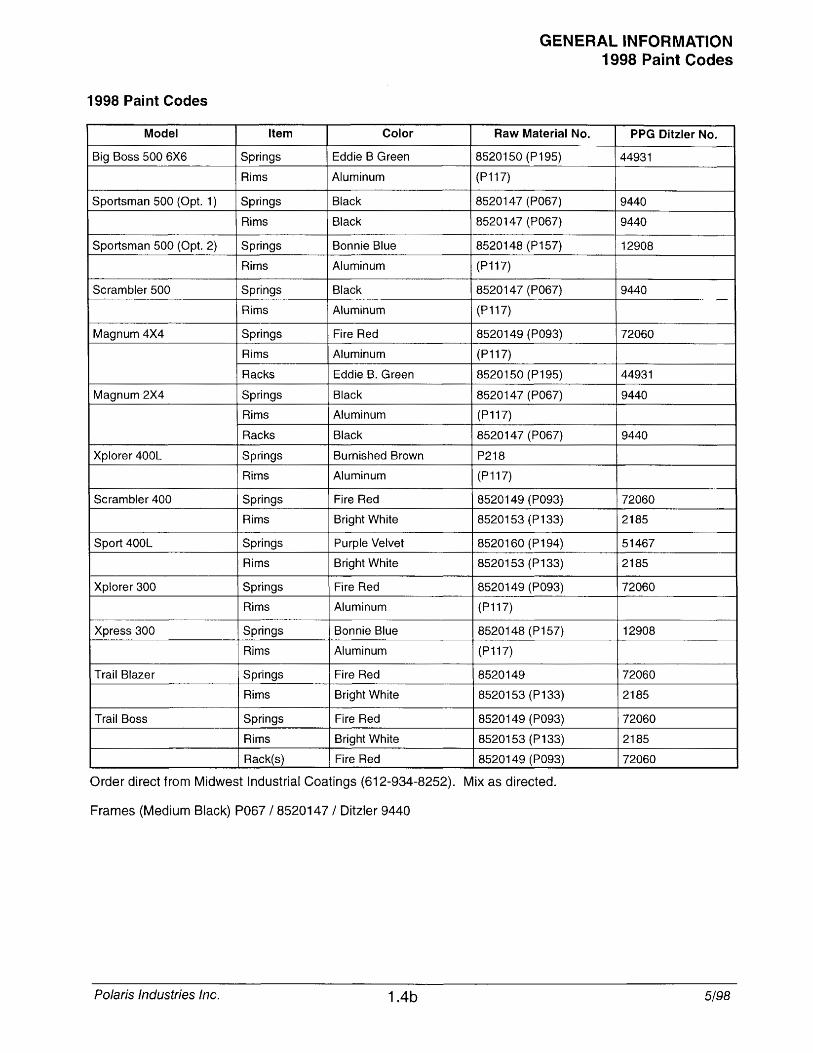
1998 Pai nt Codes
Model Item Color
Big Boss 500 6X6 Springs Eddie B Green
Rims Aluminum
Sportsman 500 (Opt. 1) Springs Black
Rims Black
Sportsman 500 (Opt. 2) Springs Bonnie Blue
Rims Aluminum
Scrambler 500 Springs Black
Rims Aluminum
Magnum 4X4 Springs Fire Red
Rims Aluminum
Racks Eddie B. Green
Magnum 2X4 Springs Black
Rims Aluminum
Racks Black
Xplorer 400L Springs Burnished Brown
Rims Aluminum
Scrambler 400 Springs Fire Red
Rims Bright White
Sport 400L Springs Purple Velvet
Rims Bright White
Xplorer 300 Springs Fire Red
Rims Aluminum
Xpress 300 Springs Bonnie Blue
Rims Aluminum
Trail Blazer Springs Fire Red
Rims Bright White
Trail Boss Springs Fire Red
Rims Bright White
Rack(s) Fire Red
GENERAL INFORMATION 1998 Paint Codes
Raw Material No. PPG Ditzler No.
8520150 (P195) 44931
(P117)
8520147 (P067) 9440
8520147 (P067) 9440
8520148 (P157) 12908
(P117)
8520147 (P067) 9440
(P117)
8520149 (P093) 72060
(P117)
8520150 (P195) 44931
8520147 (P067) 9440
(P117)
8520147 (P067) 9440
P218
(P117)
8520149 (P093) 72060
8520153 (P133) 2185
8520160 (P194) 51467
8520153 (P133) 2185
8520149 (P093) 72060
(P117)
8520148 (P157) 12908
(P117)
8520149 72060
8520153 (P133) 2185
8520149 (P093) 72060
8520153 (P133) 2185
8520149 (P093) 72060
Order direct from Midwest Industrial Coatings (612-934-8252). Mix as directed.
Frames (Medium Black) P067 / 8520147 / Ditzler 9440
Polaris Industries Inc. 1.4b 5/98
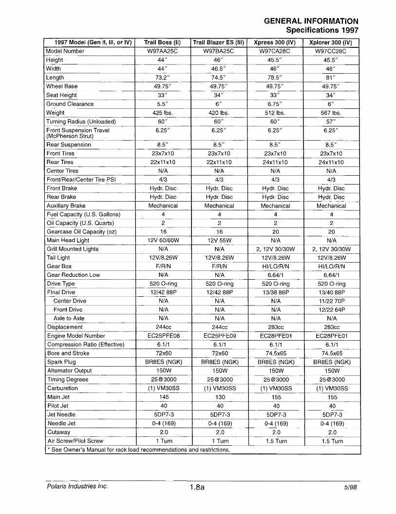
1997 Model (Gen II, III, or IV) Trail Boss (II) Trail Blazer ES (III)
Model Number W97AA25C W97BA25C
Height 44/1 46/1
Width 44/1 46.5/1
Length 73.2" 74.5" -.~ .. ,.~ .- , '"~
WheelBase 49.75/1 49.75/1
Seat Height 33/1 34/1
Ground Clearance 5.5/1 6/1
Weight 4251bs. 4201bs.
Turning Radius (Unloaded) 60/1 60/1
Front Suspension Travel 6.25/1 6.25/1 (McPherson Strut)
..... -~- - .~~-~----"". ~ [---.-
Rear Suspension 8.5/1 8.5/1
Front Tires 23x7x10 23x7x10
Rear Tires 22x11x10 22x11x10
Center Tires N/A N/A
FronVRear/Center Tire PSI 4/3 4/3 -_. ~ .. -. Front Brake ~~~ Disc Hydr. Disc
Rear Brake Hydr. Disc Hydr. Disc
Auxiliary Brake Mechanical Mechanical
Fuel Capacity (U.S. Gallons) 4 4
Oil Capacity (U.S. Quarts) 2 2
Gearcase Oil Capacity (oz) 16 16
Main Head Light 12V 60/60W 12V 55W
Grill Mounted Lights N/A N/A
Tail Light 12V/8.26W 12V/8.26W - n_. __ .
Gear Box F/R/N F/R/N
Gear Reduction Low N/A N/A
Drive Type 520 O-ring 520 a-ring -" .. ~.
Final Drive 12/4288P 12/4288P
Center Drive N/A N/A
Front Drive N/A N/A Axle to Axle N/A N/A
Displacement 244cc 244cc
Engine Model Number EC25PFE08 EC25PFE09
Compression Ratio (Effective) 6.1/1 6.1/1
Bore and Stroke 72x60 72x60
Spark Plug BR8ES (NGK) BR8ES (NGK)
Alternator Output 150W 150W
Timing Degrees 25@3000 25@3000
Carburetion (1) VM30SS (1) VM30SS
Main Jet 145 130
Pilot Jet 40 40
Jet Needle 5DP7-3 5DP7-3
Needle Jet 0-4 (169) 0-4 (169) r. •• t::l\AI::I\I 2.0 2.0 -J
Air Screw/Pilot Screw 1 Turn 1 Turn
* See Owner's Manual for rack load recommendations and restrictions.
Polaris Industries Inc. 1.8a
GENERAL INFORMATION Specifications 1997
Xpress 300 (IV) Xplorer 300 (IV)
W97CA28C W97CC28C
45.5" 45.5/1
46/1 46/1
78.5" 81/1 -----
49.75/1 49.75/1
33" 34/1
6.75/1 6/1
5121bs. 5671bs. 60/1 57"
6.25/1 6.25/1
8.5" 8.5/1
23x7x10 23x7x10
24x11 x1 0 24x11x10
N/A N/A
4/3 4/3
Hydr. Disc Hydr. Disc
Hydr. Disc Hydr. Disc
Mechanical Mechanical
4 4
2 2
20 20
N/A N/A
2, 12V 30/30W 2, 12V 30/30W
12V/8.26W 12V/8.26W
HI/LO/R/N HI/LO/R/N
6.64/1 6.64/1
520 O-ring 520 a-ring
13/3886P 13/4088P
N/A 11/2270P
N/A 12/2264P
N/A N/A
283cc 283cc
EC28PFE01 EC28PFE01
6.1/1 6.1/1
74.5x65 74.5x65
BR8ES (NGK) BR8ES (NGK)
150W 150W
25@3000 25@3000 --~~ .-
(1) VM30SS (1) VM30SS
155 155
40 40 .. 5DP7-3 5DP7-3
0-4 (169) 0-4 (169)
2.0 2.0
1.5 Turn 1.5 Turn
5/98
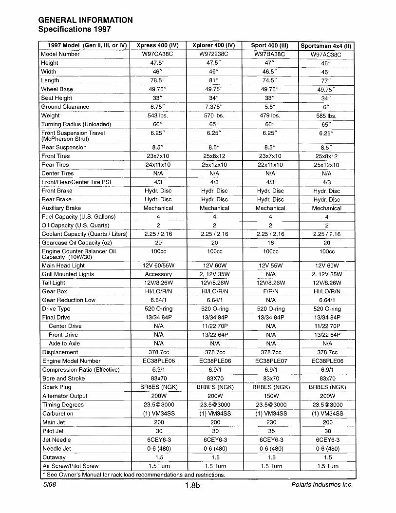
GENERAL INFORMATION Specifications 1997
1997 Model (Gen II, III, or IV)
Model Number
Height
Width --._-Length
Wheel Base
Seat Height
Ground Clearance
Weight
Turning Radius (Unloaded)
Front Suspension Travel (McPherson Strut)
Rear Suspension
Front Tires
Rear Tires
Center Tires
Front/Rear/Center Tire PSI
Front Brake
Rear Brake
Auxiliary Brake
Fuel Capacity (U.S. Gallons)
Oil Capacity (U.S. Quarts)
Coolant Capacity (Quarts / Liters)
Gearcase Oil Capacity (oz)
Engine Counter Balancer Oil Capacity (10W/30)
Main Head Light
Grill Mounted Lights
Tail Light
Gear Box ,.
Gear Reduction Low
Drive Type
Final Drive
Center Drive
Front Drive
Axle to Axle
Displacement
Engine Model Number
Compression Ratio (Effective)
Bore and Stroke
Spark Plug
Alternator Output
Timing Degrees
Carburetion
Main Jet
Pilot Jet
Jet Needle
Needle Jet
Cutaway
Air Screw/Pilot Screw r-'
Xpress 400 (IV)
W97CA38C
47.5/1
46"
78.5"
49.75"
33"
6.75/1
5431bs.
60"
6.25"
8.5"
23x7x10
24x11x10
N/A
4/3
Hydr. Disc
Hydr. Disc
Mechanical
4
2
2.25/2.16
20
100cc
12V 60/55W
Accessory
12V/8.26W
HI/LO/R/N
6.64/1
520 O-ring
13/3484P
N/A
N/A N/A
378.7cc
EC38PLE06
6.9/1
83x70
BR8ES (NGK)
200W
23.5@3000
(1) VM34SS
200
30
6CEY6-3
0-6 (480)
1.5
1.5 Turn
Xplorer 400 (IV)
W972238C
47.5"
46"
81"
49.75 11
34"
7.375"
5701bs. 65/1
6.25/1
8.5"
25x8x12
25x12x10
N/A
4/3
Hydr. Disc
Hydr. Disc
Mechanical
4
2
2.25/2.16
20
100cc
12V 60W
2, 12V 35W
12V/8.26W
HI/LO/R/N
6.64/1
520 O-ring
13/3484P
11/2270P
13/2264P
N/A
378.7cc
EC38PLE06
6.9/1
83X70
BR8ES (NGK)
200W
23.5@3000
(1) VM34SS
200
30
6CEY6-3
0-6 (480)
1.5
1.5 Turn
* See Owner's Manual for rack load recommendations and restrictions.
5/98 1.8b
Sport 400 (III) Sportsman 4x4 (II) W97BA38C W97AC38C
47/1 46/1
46.5" 46/1
74.5" 77/1
49.75" 49.75/1 33/1 34"
5.5" 6"
4791bs. 5851bs.
60" 65" 6.25/1 6.25/t
8.5" 8.5"
23x7x10 25x8x12
22x11x10 25x12x10
N/A N/A
4/3 4/3
Hydr. Disc Hydr. Disc
Hydr. Disc Hydr. Disc
Mechanical Mechanical
4 4
2 2
2.25/2.16 2.25/2.16
16 20
100cc 100cc
12V 55W 12V 60W ,,~
N/A 2, 12V 35W
12V/8.26W 12V/8.26W
F/R/N HI/LO/R/N
N/A 6.64/1
520 O-ring 520 O-ring
13/3484P 13/3484P
N/A 11/2270P
N/A 13/2264P
N/A N/A
378.7cc 378.7cc
EC38PLE07 EC38PLE06
6.9/1 6.9/1
83x70 83x70
BR8ES (NGK) BR8ES (NGK)
150W 200W
23.5@3000 23.5@3000
(1) VM34SS (1) VM34SS
230 200
35 30
6CEY6-3 6CEY6-3
0-6 (480) 0-6 (480)
1.5 1.5
1.5 Turn 1.5 Turn
Polaris Industries Inc.
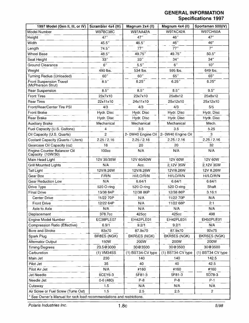
1997 Model (Gen II, III, or IV) Scrambler 4x4 (III) Magnum 2x4 (II)
Model Number W97BC38C W97AA42A
Height 47" 47/1
Width 45.5" 46.5"
~ngtl 74.5" 77"
Wheel Base 48.5/1 49.75"
Seat Height 33" 33"
Ground Clearance 6/1 5.5"
Weight 4901bs. 5341bs.
Tuming Radius (Unloaded) 60" 60"
Front Suspension Travel 8.5/1 6.25" (McPherson Strut)
Rear Suspension 8.5" 8.5" --
Front Tires 23x7x10 23x7x10
Rear Tires 22x11x10 24x11x10
Front/Rear/Center Tire PSI 4/3 4/3
Front Brake Hydr. Disc Hydr. Disc
Rear Brake Hydr. Disc Hydr. Disc
Auxiliary Brake Mechanical Mechanical
Fuel Capacity (U.S. Gallons) 4 3.5
Oil Capacity (U.S. Quarts) 2 2- OW40 Engine Oil
Coolant Capacity (Quarts / Liters) 2.25/2.16 2.25/2.16
Gearcase Oil Capacity (oz) 16 20
Engine Counter Balancer Oil 100cc N/A Capacity (10W/30)
Main Head Light 12V 35/35W 12V 60/60W
Grill Mounted Lights N/A Ace.
Tail Light 12V/8.26W 12V/8.26W
Gear Box F/R/N HI/LO/R/N
Gear Reduction Low N/A 6.64/1 ,-
Drive Type 520 O-ring 520 ing
Final Drive 13/3884P 12/3886P
Center Drive 11/2270P N/A
Front Drive 12/2264P N/A
Axle to Axle N/A N/A
Displacement 378.7cc 425cc
Engine Model Number EC38PLE07 EH42PLE01
Compression Ratio (Effective) 6.9/1 9.2/1
Bore and Stroke 83x70 87.9x70
Spark Plug BR8ES (NGK) BKR5ES (NGK)
Alternator Output 150W 200W
Timing Degrees 23.5@3000 30@3500 .. _-".,--
Carburetion (1) VM34SS (1) BST34-CV type
Main Jet 230 140
Pilot Jet 35 40 --Pilot Air Jet N/A #160
Jet Needle 6CEY6-3 5F81-3
Needle Jet 0-6 (480) P-8
Cutaway 1.5 N/A
Air Screw or Fuel Screw (Tums Out) 1.5 2.5
* See Owner's Manual for rack load recommendations and restrictions.
Polaris Industries Inc. 1.8c
GENERAL INFORMATION Specifications 1997
Magnum 4x4 (II) Sportsman 500(IV)
W97AC42A W97CH50A 46/1 47" 46/1 46"
77" 7"
49.75" 50.5"
34" 34"
6" 10"
5951bs. 6491bs.
65" 65"
6.25" 6.25"
8.5" 9.5"
25x8x12 25x8x12
25x12x10 25x12x10
4/3 5/5
Hydr. Disc Hydr. Disc
Hydr. Disc Hydr. Disc
Mechanical Mech.
3.5 5.25
2- OW40 Engine Oil 3
2.25/2.16 2.25/2.16
20 32
N/A N/A
12V 60W 12V 60W
2,12V 35W 2,12V 35W
12V/8.26W 12V 8.26W
HIILO/R/N HIILO/R/N
6.64/1 6.64/1
520 O-ring Shaft
1213886P 3.16:1
11/2270P N/A
11/2268P 2:1
N/A N/A
425cc 498
EH42PLE01 EH50PLE01
9.211 N/A
87.9x70 92x75
BKR5ES (NGK) BKR5ES (NGK)
200W 200W
30@3500 30@3500
(1) BST34-CV type (1) BST34 Cv.., type
140 142.5
40 42.5
#160 #160
5F81-3 5078-3
P-8 P-1
N/A N/A
2.5 2 -- --
5/98
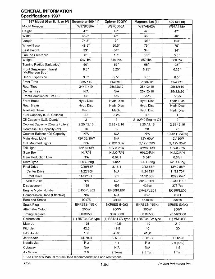
GENERAL INFORMATION Specifications 1997
1997 Model (Gen II, III, or IV)
Model Number
Height
Width
Length
Wheel Base
Seat Height
Ground Clearance
Weight
Turning Radius (Unloaded)
Front Suspension Travel (McPherson Strut)
Rear Suspension
Front Tires
Rear Tires
Center Tires
Front/Rear/Center Tire PSI
Front Brake
Rear Brake
Auxiliary Brake
Fuel Capacity (U.S. Gallons)
Oil Capacity (U.S. Quarts)
Coolant Capacity (Quarts / Liters)
Gearcase Oil Capacity (oz)
Counter Balancer Oil Capacity
Main Head Light
Grill Mounted Lights
Tail Light
Gear Box
Gear Reduction Low
Drive Type
Final Drive
Center Drive
Front Drive
Axle to Axle
Displacement
Engine Model Number
Compression Ratio (Effective)
Bore and Stroke
Spark Plug
Alternator Output
Timing Degrees ----~~,.,
Carburetion
Main Jet
Pilot Jet
Pilot Air Jet
Jet Needle
Needle Jet
Cutaway 1--------_ .. ...
Air Screw
Scrambler 500 (III)
W97BC50A
47"
45.5"
74.5"
48.5"
33"
6"
5471bs.
60"
8.5"
9.5"
23x7X10
24x11x10
N/A --_.
4/3
Hydr. Disc
Hydr. Disc
Mech.
3.5
2
2.25/2.16
16
N/A
12V 35/35W
N/A
12V 8.26W
HIIR/N
N/A
520 O-ring
12/38/86P
11/22/70P
11/22/68P
N/A
498
EH50PLE02
N/A
92x75
BKR5ES (NGK)
200W
30@3S00
(1) BST34 CV type
125
42.S
160
SD78-3
P-3
N/A ---.. ~-- ... ~
2.0
Xplorer 500(lV)
W97CD50A
47"
46"
7"
50.5"
34"
10"
6491bs.
65"
6.25"
9.5"
25x8x12
25x12x10 .. ~ ..
N/A
5/5
Hydr. Disc
Hydr. Disc
Mech.
5.25
3
2.25/2.16
32
N/A
N/A
2,12V 35W
12V 8.26W
HI/LO/R/N
6.64/1
Shaft
3.16:1
N/A
2:1
N/A
498
EH50PLE01
N/A
92x75
BKRSES (NGK)
200W
30@3S00
(1) BST34 CV type
142.5
42.S
#160
5078-3
P-1
N/A
2 Turns
.. See Owner's Manual for rack load recommendations and restrictions.
5/98 1.8d
Magnum 6x6 (II) 400 6x6 (II)
W97AE42A W97AE38A 47/1 47/1
46/1 46/1
103/1 103"
75" 75"
34" 34"
5.5" 5.5"
8521bs. 8301bs. 98/1 98/1
6.25" 6.25"
8.5" 8.5" 25x8x12 25x8x12
25x12x10 25x12x10
25x12x10 25x12x10
5/5/5 5/5/5
Hydr. Disc Hydr. Disc
Hydr. Disc Hydr. Disc
Hydr. Disc Hydr. Disc
3.5 4
2- OW40 Engine Oil 2
2.25/2.16 2.25/2.16
20 20
N/A 100cc (1 OW30)
12V 60W 12V 60W
2,12V 35W 2, 12V 35W
12V/8.26W 12V/8.26W
HI/LO/R/N HIILO/R/N
6.64/1 6.64/1
520 O-ring 520 O-ring
1214288P 13/4288P
11/2472P 11/2270P
11/2268P 1212264P
30/30 116P 30/30 116P
425cc 378.7cc
EH42PLE01 EC38PLE06
9.2/1 6.9/1
87.9x70 83x70
BKRSES (NGK) BR8ES (NGK)
200W 200W .. _-_.-
30@3500 23.5@3000
(1) BST34-CV type (1) VM34SS
140 210
40 30
#160
5F81-3 6DH29-3
P-8 0-6 (480)
N/A 1.5
2.5 Turn 1 Turn
Polaris Industries Inc.
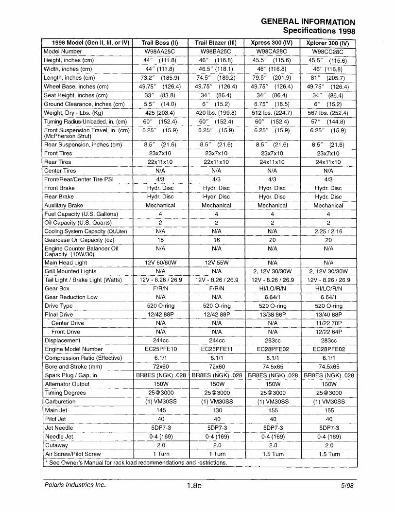
1998 Model (Gen II, III, or IV) Trail Boss (II) Trail Blazer (III)
Model Number W98AA25C W98BA25C
Height, inches (cm) 44/1 (111.8) 46/1 (116.8)
Width, inches (cm) 44/1 (111.8) 46.5/1 (118.1)
Length, inches (cm) 73.2/1 (185.9) 74.5" (189.2)
Wheel Base, inches (cm) 49.75/1 (126.4) 49.75/1 ( 26.4)
Seat Height, inches (cm) 33 '1 (83.8) 34/1 (86.4)
Ground Clearance, inches (cm) 5.5/1 (14.0) 6/1 (15.2)
Weight, Dry - Lbs. (Kg) 425 (203.4) 420 Ibs. (199.8)
Turning Radius-Unloaded, in. (cm) 60 11 (1S2.4) 60 '1 (152.4)
Front Suspension Travel, in. (cm) 6.25/1 (15.9) 6.25 '1 (15.9) (McPherson Strut)
Rear Suspension, inches (cm) 8.5 '1 (21.6) 8.5" (21.6)
Front Tires 23x7x10 23x7x10
Rear Tires 22x11x10 22x11x10
Center Ti res N/A N/A Front/Rear/Center Tire PSI 4/3 4/3
Front Brake Hydr. Disc Hydr. Disc
Rear Brake Hydr. Disc Hydr. Disc
Auxiliary Brake Mechanical Mechanical
Fuel Capacity (U.S. Gallons) 4 4
Oil Capacity (U.S. Quarts) 2 2
Cooling System Capacity (Qt'/Liter) N/A N/A
Gearcase Oil Capacity (oz) 16 16 I-----.. -~---
Engine Counter Balancer Oil N/A N/A Capacity (10W/30)
Main Head Light 12V 60/60W 12V 55W
Grill Mounted Lights N/A N/A Tail Light 1 Brake Light (Watts) 12V - 8.26/26.9 12V - 8.26/26.9
Gear Box F/R/N F/R/N
Gear Reduction Low N/A N/A .-r----'
Drive Type 520 O-ring 520 O-ring
Final Drive 12/4288P 1214288P
Center Drive N/A N/A Front Drive N/A N/A
Displacement 244cc 244cc
Engine Model Number EC25PFE10 EC25PFE11
Compression Ratio (Effective) 6.1/1 6.1/1
Bore and Stroke (mm) 72x60 72x60
Spark Plug 1 Gap, in. BR8ES (NGK) .028 BR8ES (NGK) .028
Alternator Output 150W 150W
Timing Degrees 2S@3000 25@3000
Carburetion (1) VM30SS (1) VM30SS
Main Jet 145 130
Pilot Jet 40 40
Jet Needle SDP7-3 SDP7-3
Needle Jet 0-4 (169) 0-4 (169)
Cutaway 2.0 2.0
Air Screw/Pilot Screw 1 Turn 1 Turn
* See Owner's Manual for rack load recommendations and restrictions.
Polaris Industries Inc. 1.8e
GENERAL INFORMATION Specifications 1998
Xpress 300 (IV) Xplorer 300 (IV)
W98CA28C W98CC28C 45.5/1 (115.6) 45.5/1 (115.6)
46" (116.8) 46/1 (116.8)
79.5/1 (201.9) 81/1 (205.7)
49.75/1 (126.4) 49.75 /1 \126.4)
34 /1 (86.4) 34" (86.4)
6.75/1 (16.5) 6" (15.2)
512 Ibs. (224.7) 567 Ibs. (252.4)
60" (152.4) 57 /1 (144.8)
6.25" (15.9) 6.25" (15.9)
8.S" (21.6) 8.5 '1 (21.6)
23x7x10 23x7x10 --
24x11x10 24x11x10
N/A N/A 4/3 4/3
Hydr. Disc Hydr. Disc .----.---
Hydr. Disc Hydr. Disc
Mechanical Mechanical
4 4
2 2
N/A 2.25/2.16
20 20
N/A N/A
N/A N/A
2, 12V 30/30W 2, 12V 30/30W
12V - 8.26 1 26.9 12V - 8.261 26.9 _. __ .. _---HIILO/R/N HIILO/R/N
6.64/1 6.64/1
520 O-ring 520 O-ring
13/3886P 13/4088P
N/A 11/2270P
N/A 12/2264P
283cc 283cc
EC28PFE02 EC28PFE02
6.1/1 6.1/1
74.5x65 74.5x65
BR8ES (NGK) .028 BR8ES (NGK) .028
150W 150W
25@3000 25@3000
(1) VM30SS (1) VM30SS
155 155
40 40
5DP7-3 5DP7-3
0-4 (169) 0-4 (169)
2.0 2.0
1.5 Turn 1.5 Turn
5/98
GENERAL INFORMATION Specifications 1998
1998 Model (Gen II, III, or IV)
Model Number
Height, inches (cm)
Width, inches (cm)
Length, inches (cm)
Wheel Base, inches (I 1)
Seat Height, inches (cm)
Ground Clearance, inches (cm)
Weight - Lbs. (Kg)
Turning Radius (Unloaded), in.(crn)
Front Suspension Travel (McPherson Strut)
Rear Suspension
Front Tires
Rear Tires
Front/Rear/Center Tire PSI
Front Brake
Rear Brake
Auxiliary Brake
Fuel Capacity (U.S. Gallons)
Oil Capacity (U.S. Quarts)
Cooling System Capacity-qt (liter)
Gearcase Oil Capacity (oz)
Engine Counter Balancer Oil Capacity (10W/30)
Main Head Light ~.
Grill Mounted Lights
Tail Light / Brake Light (Watts)
Gear Box
Gear Reduction Low
Drive Type
Final Drive
Center Drive
Front Drive
Axle to Axle
Displacement
Engine Model Number
Compression Ratio (Effective)
Bore and Stroke
Spark Plug
Alternator Output
Timing Degrees
Carburetion
Main Jet
Pilot Jet
Jet Needle
Needle Jet
Cutaway
Air Screw/Pilot Screw
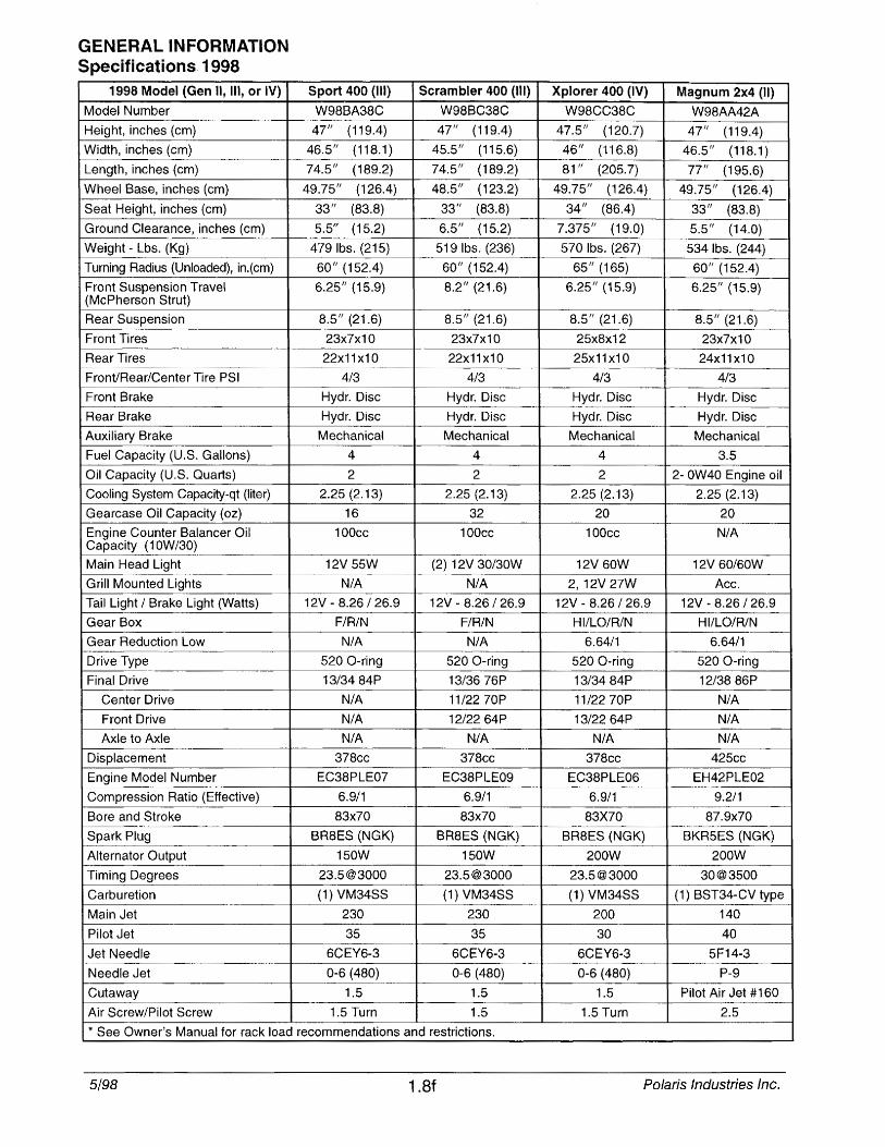
Sport 400 (III)
W98BA38C
47" (119.4)
46.5 11 (118.1)
74.5 11 (189.2)
49.75/1 ( f)
33 11 (83.8)
5.5" (15.2)
4791bs. (215)
60" (152.4)
6.25 11 (15.9)
8.5" (21.6)
23x7x10
22x11x10
4/3
Hydr. Disc
Hydr. Disc
Mechanical
4
2
2.25 (2.13)
16
100cc
12V 55W
N/A
12V - 8.26/26.9
F/R/N
N/A
520 O-ring
13/3484P
N/A
N/A
N/A
378cc
EC38PLE07
6.9/1 -- . 83x70
BR8ES (NGK)
150W
23.5@3000
(1) VM34SS
230
35
6CEY6-3
0-6 (480) ---
1.5
1.5 Turn
Scrambler 400 (III)
W98BC38C 47/1 (119.4)
45.5 11 (115.6)
74.5/1 (189.2)
48.5" (123.2)
33" (83.8)
6.5/1 (15.2)
519 Ibs. (236)
60 11 (152.4)
8.211 (21.6)
8.5" (21.6)
23x7x10
22x11x10
4/3
Hydr. Disc
Hydr. Disc
Mechanical
4
2
2.25 (2.13)
32
100cc
(2) 12V 30/30W
N/A
12V - 8.26/26.9
F/R/N
N/A
520 O-ring
13/3676P
11/2270P
12/2264P
N/A
378cc
EC38PLE09
6.9/1
83x70
BR8ES (NGK)
150W
23.5@3000
(1) VM34SS ~, "
230
35
6CEY6-3
0-6 (480)
1.5
1.5
* See Owner's Manual for rack load recommendations and restrictions.
5/98 1.8f
Xplorer 400 (IV) Magnum 2x4 (II)
W98CC38C W98AA42A
47.5" (120.7) 47" (119.4)
46 11 (116.8) 46.5 11 (118.1) 81/1 (205.7) 77/1 (195.6)
49.75" (126.4) 49.75 11 (126.4) 34/1 (86.4) 33/1 (83.8)
7.375" (19.0) 5.5/1 (14.0)
570 Ibs. (267) 534 Ibs. (244)
65/1 (165) 60/1 (152.4)
6.25" (15.9) 6.25" (15.9)
8.5" (21.6) 8.5 11 (21.6)
25x8x12 23x7x10
25x11x10 24x11x10
4/3 4/3 -
Hydr. Disc Hydr. Disc
Hydr. Disc Hydr. Disc
Mechanical Mechanical
4 3.5
2 2- OW40 Engine oil
2.25 (2.13) 2.25 (2.13)
20 20
100cc N/A
12V 60W 12V 60/60W
2, 12V 27W Acc.
12V - 8.26 / 26.9 12V - 8.26/26.9
HIILO/R/N HI/LO/R/N .. ---
6.64/1 6.64/1 •..
520 O-ring 520 O-ring
13/3484P 12/3886P
11/2270P N/A
13/2264P N/A
N/A N/A
378cc 425cc
EC38PLE06 EH42PLE02
6.9/1 9.2/1
83X70 87.9x70 .. -~~.~--
BR8ES (NGK) BKR5ES (NGK)
200W 200W
23.5@3000 30@3500
(1) VM34SS (1) BST34-CV type
200 140
30 40
6CEY6-3 5F14-3
0-6 (480) P-9
1.5 Pilot Air Jet #160
1.5 Turn 2.5
Polaris Industries Inc.
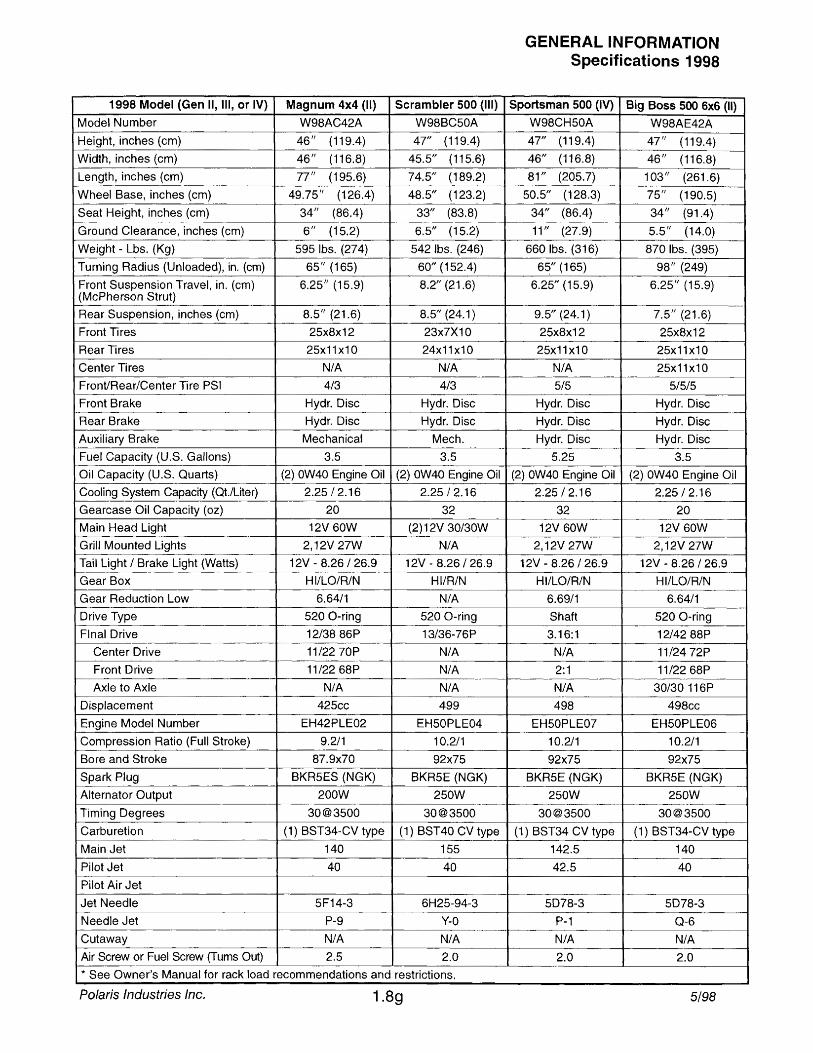
1998 Model (Gen II, III, or IV) Magnum 4x4 (II) Scrambler 500 (III)
Model Number W98AC42A W98BC50A
Height, inches (cm) 46/1 (119.4) 47/1 (119.4)
Width, inches (cm) 46/1 (116.8) 45.5" (115.6)
Length, inches (cm) 77/1 (195.6) 74.5/1 (189.2)
Wheel Base, inches (cm) 49.75/1 (126.4) 48.5" (123.2)
Seat Height, inches (I 1) 34/1 (86.4) 33" (83.8)
Ground Clearance, inches (cm) 6" (15.2) 6.5/1 (15.2)
Weight - Lbs. (Kg) 595 Ibs. (274) 542 Ibs. (246)
Turning Radius (Unloaded), in. (cm) 65" (165) 60" (152.4)
Front Suspension Travel, in. (cm) 6.25/1 (15.9) 8.2" (21.6) (McPherson Strut)
Rear Suspension, inches (cm) 8.5" (21.6) 8.5/1 (24.1)
Front Tires 25x8x12 23x7X10
Rear Tires 25x11x10 24x11x10
Center Tires N/A N/A
Front/Rear/Center Tire PSI 4/3 4/3
Front Brake Hydr. Disc Hydr. Disc
Rear Brake Hydr. Disc Hydr. Disc
Auxiliary Brake Mechanical Mech.
Fuel Capacity (U.S. Gallons) 3.5 3.5
Oil Capacity (U.S. Quarts) (2) OW40 Engine Oil (2) OW40 Engine Oil
Cooling System Capacity (Qt./Liter) 2.25/2.16 2.25 I 2.16
Gearcase Oil Capacity (oz) 20 32
Main Head Light 12V 60W (2) 12V 30/30W
Grill Mounted _Li~ 2,12V 27W N/A
Tail Light 1 Brake Light (Watts) 12V - 8.26/26.9 12V ~ 8.26 I 26.9 -,
Gear Box HIILO/R/N HI/R/N
Gear Reduction Low 6.64/1 N/A
Drive Type 520 O~ring ~--
520 a-ring
Final Drive 12/3886P 13/36-76P ,-Center Drive 11/2270P N/A Front Drive 11/2268P N/A
Axle to Axle N/A N/A
Displacement 425cc 499
Engine Model Number EH42PLE02 EH50PLE04
Compression Ratio (Full Stroke) 9.2/1 10.2/1
Bore and Stroke 87.9x70 92x75
Spark Plug BKR5ES (NGK) BKR5E (NGK)
Alternator Output 200W 250W .. -
Timing Degrees 30@3500 30@3500
Carburetion (1) BST34-CV type (1) BST 40 CV type
Main Jet 140 155
Pilot Jet 40 40
Pilot Air Jet
Jet Needle 5F14-3 6H25-94-3
Needle Jet P-9 y-O --
Cutaway N/A N/A Air Screw or Fuel Screw (Turns Out) 2.5 2.0
* See Owner's Manual for rack load recommendations and restrictions.
Polaris Industries Inc. 1.89
GENERAL INFORMATION Specifications 1998
Sportsman 500 (IV) Big Boss 500 6x6 (II)
W98CH50A W98AE42A 47/1 (119.4) 47/1 (119.4)
46" (116.8) 46" (116.8)
81" (205.7) 103" (261.6)
50.5/1 (128.3) 75" (190.5)
34" (86.4) 34/1 (91.4)
11 " (27.9) 5.5/1 (14.0)
660 Ibs. (316) 870 Ibs. (395)
65" (165) 98" (249)
6.25" (15.9) 6.25" (15.9)
9.5" (24.1) 7.5" (21.6)
25x8x12 25x8x12 -
25x11x10 25x11x10
N/A 25x11x10
5/5 5/5/5
Hydr. Disc Hydr. Disc
Hydr. Disc Hydr. Disc
Hydr. Disc Hydr. Disc
5.25 3.5
(2) OW40 Engine Oil (2) OW40 Engine Oil
2.25 I 2.16 2.25 I 2.16
32 20
12V 60W 12V 60W
2,12V 27W 2,12V 27W
12V - 8.26 I 26.9 12V ~ 8.26 1 26.9
HI/LO/R/N HIILO/R/N
6.69/1 6.64/1
Shaft 520 a-ring
3.16:1 1214288P
N/A 11/2472P
2:1 11/2268P
N/A 30/30 116P
498 498cc
EH50PLE07 EH50PLE06
10.211 10.2/1
92x75 92x75
BKR5E (NGK) BKR5E (NGK)
250W 250W
30@3500 30@3500
(1) BST34 CV type (1) BST34-CV type
142.5 140
42.5 40
5078-3 5078-3
P-1 Q-6
N/A N/A
2.0 2.0
5/98
--,
-,-

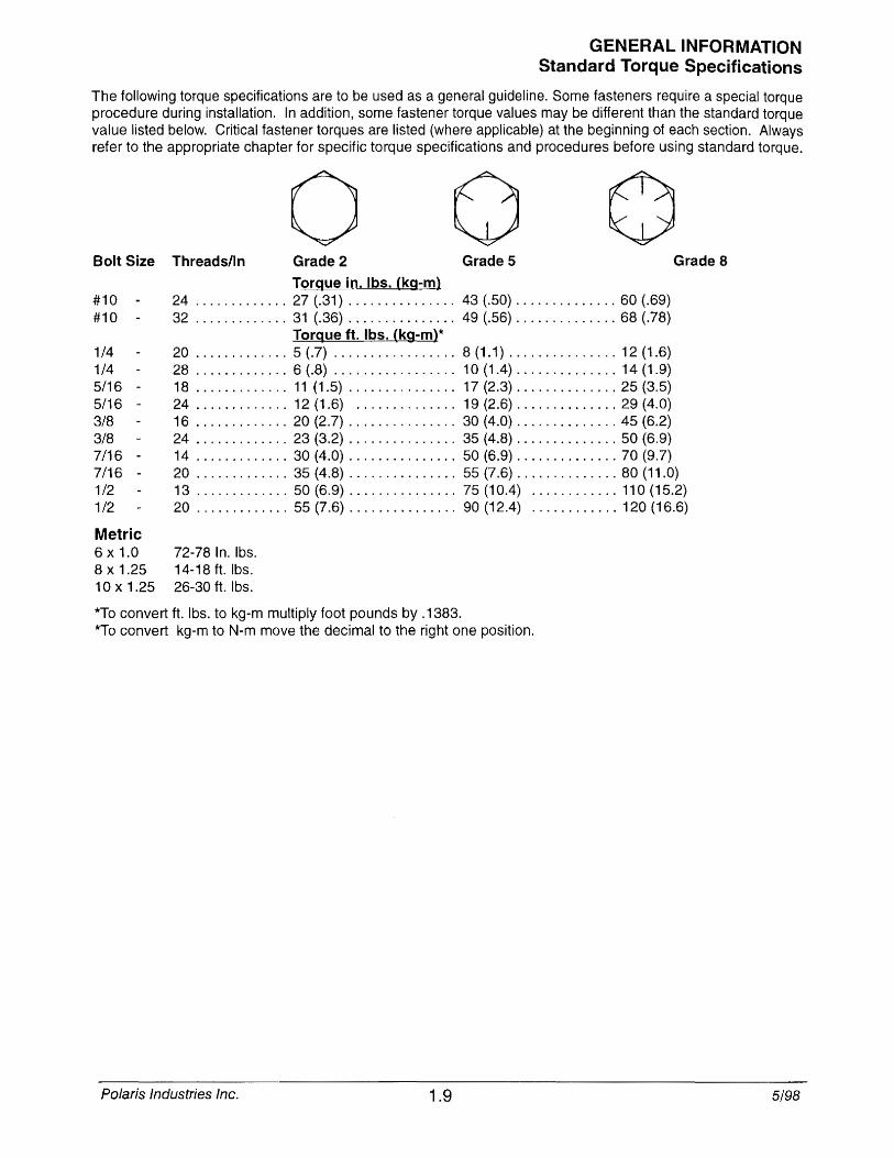
GENERAL INFORMATION Standard Torque Specifications
The following torque specifications are to be used as a general guideline. Some fasteners require a special torque procedure during installation. In addition, some fastener torque values may be different than the standard torque value listed below. Critical fastener torques are listed (where applicable) at the beginning of each section. Always refer to the appropriate chapter for specific torque specifications and procedures before using standard torque.
o Bolt Size Threads/In Grade 2 Grade 5
#10 8
#10 -
1/4 1/4 5/16 -5/16 -3/8 3/8
Torgue in. Ibs. (kg~m) 24 ............. 27 (.31) ............... 43 (.50) .............. 60 (.69) 32 ............. 31 (.36) ............... 49 (.56) .............. 68 (.78)
Torgue ft. Ibs. (kg~m)* 20 ............. 5 (.7) ................. 8(1.1) ............... 12{1.6) 28 ............. 6 (.8) ................. 10 {1.4} .............. 14 (1.9) 18 ............. 11 (1.5) ............... 17 (2.3) .............. 25 (3.5) 24 ............. 12 (1.6) .............. 19 (2.6} .............. 29 (4.0) 16 ............. 20 (2.7) ............... 30 (4.0) .............. 45 (6.2) 24 ............. 23 (3.2) ............... 35 (4.8) .............. 50 (6.9) 14 ............. 30 (4.0) ............... 50 (6.9) .............. 70 (9.7)
Grade 8
7/16 -7/16 -1/2
20 ............. 35 (4.8) ............... 55 (7.6) .............. 80 (11.0)
1/2
Metric 6 x 1.0 8 x 1.25 10 x 1.25
13 ............. 50(6.9) ............... 75(10.4) ............ 110{15.2) 20 ............. 55 (7.6) ............... 90 (12.4) ............ 120 (16.6)
72 8 78 In. Ibs. 14-18 ft. Ibs. 26-30 ft. Ibs.
*To convert ft. Ibs. to kg-m multiply foot pounds by .1383. *To convert kg-m to N-m move the decimal to the right one position.
Polaris Industries Inc. 1.9 5/98
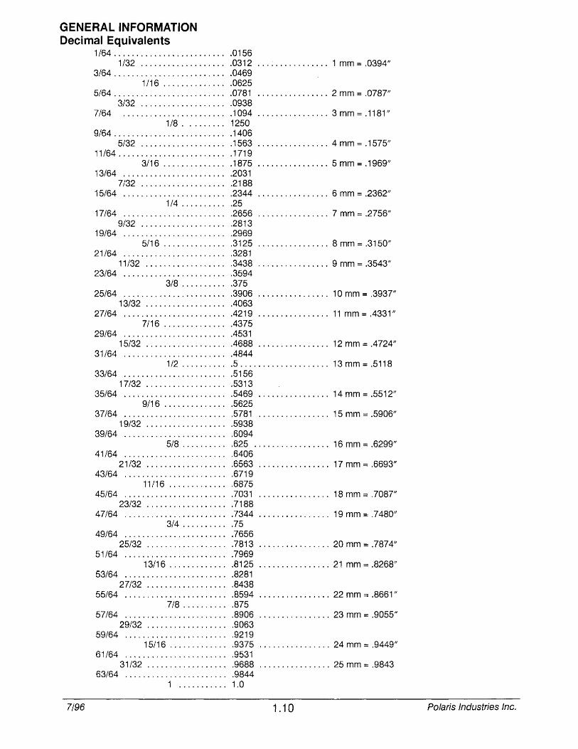
GENERAL INFORMATION Decimal Equivalents
1/64 .......................... 0156 1/32 .................... 0312 ................ 1 mm = .0394//
3/64 .......................... 0469 1/16 ............... 0625
5/64 .......................... 0781 ................ 2 mm = .0787" 3/32 .................... 0938
7/64 .. . . . . . . . . . . . . . . . . . . . .. .1 094 ................ 3 mm = .11 81" 1/8 ......... 1250
9/64 .......................... 1406 5/32 .................... 1563 ................ 4 mm = .1575"
11/64 ......................... 1719 3/16 .............. .1875 ................ 5 mm = .1969"
13/64 ........................ 2031 7/32 .................... 2188
15/64 ....................... .2344 ................ 6 mm = .2362" 1/4 ........... 25
17/64 ....................... .2656 ................ 7 mm = .2756" 9/32 .................... 2813
19/64 ........................ 2969 5/16 ............... 3125 ................ 8 mm = .3150"
21/64 ....................... .3281 11/32 .................. .3438 ................ 9 mm = .3543"
23/64 ........................ 3594 3/8 ........... 375
25/64 ....................... .3906 ................ 10 mm = .3937" 13/32 .................. .4063
27/64 ........................ 4219 ................ 11 mm = .4331" 7/16 .............. .4375
29/64 ....................... .4531 15/32 .................. .4688 ................ 12 mm = .472411
31/64 ........................ 4844 1/2 . . . . . . . . .. .5.................... 13 mm = .5118
33/64 ........................ 5156 17/32 ................... 5313
35/64 ....................... .5469 ................ 14 mm = .551211 9/16 ............... 5625
37/64 ....................... .5781 ................ 15 mm = .5906// 19/32 ................... 5938
39/64 ........................ 6094 5/8 ........... 625 ................. 16 mm = .6299"
41/64 ........................ 6406 21/32 ................... 6563 ................ 17 mm = .6693"
43/64 ........................ 6719 11/16 .............. 6875
45/64 ....................... .7031 ................ 1 8 mm = .7087" 23/32 ................... 7188
47/64 ........................ 7344 ................ 19 mm = .7480" 3/4 ........... 75
49/64 ........................ 7656 25/32 ................... 7813 ................ 20 mm = .7874"
51/64 ........................ 7969 13/16 .............. 8125 ................ 21 mm = .8268"
53/64 ........................ 8281 27/32 ................... 8438
55/64 ........................ 8594 ................ 22 mm = .8661" 7/8 ........... 875
57/64 ........................ 8906 ................ 23 mm = .9055" 29/32 ................... 9063
59/64 ........................ 9219 15/16 . . . . . . . . . . . .. .9375 ................ 24 mm = .9449/1
61/64 ........................ 9531 31/32 .................. .9688 ................ 25 mm = .9843
63/64 ........................ 9844 1 ........... 1.0
7/96 1.10 Polaris Industries Inc.
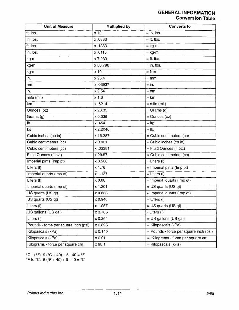
Unit of Measure
ft. Ibs.
in.lbs.
ft. Ibs.
in.lbs.
kg-m
kg-m
kg-m
in.
mm
in.
mile (mi.)
km
Ounces (oz)
Grams (g)
lb.
kg
Cubic inches (cu in)
Cubic centimeters (cc)
Cubic centimeters (cc)
Fluid Ounces (fl.oz.)
Imperial pints (Imp pt)
Liters (I)
Imperial quarts (Imp qt)
Liters (I)
Imperial quarts (Imp qt)
US quarts (US qt)
US quarts (US qt)
Liters (I)
US gallons (US gal)
Liters (I)
Pounds - force per square inch (psi)
Kilopascals (kPa)
Kilopascals (kPa)
Kilograms - force per square cm
°C to OF: 9 (OC + 40) 5 - 40 :::: OF OF to °C: 5 (OF + 40) + 9 - 40 = °C
Polaris Industries Inc.
Multiplied by
x12
x.0833
x.1383
x.0115
x 7.233
x 86.796
x10
x 25.4
x.03937
x 2.54
x 1.6
x.6214
x 28.35
x 0.035
x.454
x 2.2046
x 16.387
x 0.061
x.03381
x 29.57
x 0.568
x 1.76
x 1.137
x 0.88
x 1.201
x 0.833
x 0.946
x 1.057
x 3.785
x 0.264
x 6.895
x 0.145
x 0.01
x 98.1
1.11
GENERAL INFORMATION Conversion Table .
Converts to :::: in. Ibs.
= ft. Ibs.
:::: kg-m
kg-m
= ft. Ibs.
:::; in.lbs.
;;:Nm
::::mm
:;:: in.
::::cm
;;:km
mile (mi.)
Grams (g)
= Ounces (oz)
;;: kg
:::: lb.
Cubic centimeters (cc)
:::: Cubic inches (cu in)
:::: Fluid Ounces (fl.oz.)
:::: Cubic centimeters (cc)
:::: Liters (I)
:::: Imperial pints (Imp pt)
== Liters (1)
== Imperial quarts (Imp qt)
US quarts (US qt)
== Imperial quarts (Imp qt)
== Liters (I)
== US quarts (US qt)
=Liters (I)
:::: US gallons (US gal)
== Kilopascals (kPa)
= Pounds - force per square inch (psi)
== Kilograms - force per square cm
== Kilopascals (kPa)
5/98
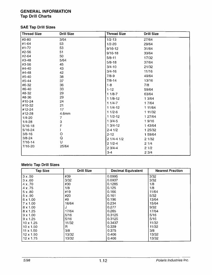
GENERAL INFORMATION Tap Drill Charts
SAE Tap Drill Sizes
Thread Size Drill Size
#0-80 3/64 #1-64 53 #1-72 53 #2-56 51 #2-64 50 #3-48 5/64 #3-56 45 #4-40 43 #4-48 42 #5-40 38 #5-44 37 #6-32 36 #6-40 33 #8-32 29 #8-36 29 #10-24 24 #10-32 21 #12-24 17 #12-28 4.6mm 1/4-20 7 1/4-28 3 5/16-18 F 5/16-24 I 3/8-16 0 3/8-24 Q 7/16-14 U 7/16-20 25/64
Metric Tap Drill Sizes
Tap Size
3 x .50 #39 3 x .60 3/32 4 x .70 #30 4 x .75 1/8 5 x .80 #19 5 x .90 #20 6 x 1.00 #9 7 x 1.00 16/64 8 x 1.00 J 8 x 1.25 17/64 9 x 1.00 5/16 9 x 1.25 5/16 10 x 1.25 11/32 10 x 1.50 R 11 x 1.50 3/8 12 x 1.50 13/32 12 x 1.75 13/32
5/98
Thread Size Drill Size
1/2-13 27/64 1/2-20 29/64 9/16-12 31/64 9/16-18 33/64 5/8-11 17/32 5/8-18 37/64 3/4-10 21/32 3/4-16 11/16 7/8-9 49/64 7/8-14 13/16 1-8 7/8 1-12 59/64 1 1/8-7 63/64 1 1/8-12 1 3/64 1 1/4-7 1 7/64 1 1/4-12 1 11/64 1 1/2-6 1 11/32 1 1/2-12 1 27/64 1 3/4-5 1 9/16 1 3/4-12 1 43/64 2-4 1/2 1 25/32 2-12 1 59/64 2 1/4-4 1/2 2 1/32 2 1/2-4 2 1/4 2 3/4-4 2 1/2 3-4 2 3/4
Drill Size Decimal Equivalent Nearest Fraction
0.0995 3/32 0.0937 3/32 0.1285 1/8 0.125 1/8 0.166 11/64 0.161 5/32 0.196 13/64 0.234 15/64 0.277 9/32 0.265 17/64 0.3125 5/16 0.3125 5/16 0.3437 11/32 0.339 11/32 0.375 3/8 0.406 13/32 0.406 13/32
1.12 Polaris Industries Inc.
LIMITED WARRANTY
GENERAL INFORMATION Warranty
Polaris Industries Inc., 1225 Highway 169 North, Minneapolis, Minnesota 55441-5078, gives a SIX MONTH LIMITED WARRANTY on all components of the Polaris All Terrain Vehicle (ATV) against defects in material or workmanship. This warranty covers the parts and labor charges for repair or replacement of defective parts which are covered by this warranty. This warranty begins on the date of purchase. This warranty is transferrable to another consumer during the warranty period through a Polaris dealer. There is a charge of $35.00 payable to Polaris Industries Inc.
REGISTRATION At the time of sale, the Warranty Registration Form must be completed by your dealer and submitted to Polaris within ten days. Upon receipt of this registration, Polaris will record the registration for warranty. THE PURCHASER MUST COMPLETE AN ATV SAFETY TRAINING COURSE PROVIDED BY THE DEALER IN ORDER TO HAVE VALID WARRANTY ON THE ATV. No verification of registration will be sent to the purchaser as the copy of the Warranty Registration Form will be the warranty entitlement. If you have not signed the original registration and received the "customer copy", please contact your dealer immediately. NO WARRANTY COVERAGE WILL BE ALLOWED UNLESS YOUR ATV IS REGISTERED WITH POLARIS.
Initial dealer preparation and set-up of your ATV is very important in ensuring trouble-free operation. Purchasing a machine in the crate or without proper dealer set-up will void your warranty coverage.
WARRANTY COVERAGE AND EXCLUSIONS: LIMITATIONS OF WARRANTIES AND REMEDIES The Polaris limited warranty excludes any failures that are not caused by a defect in material or workmanship. This warranty does not cover accidental damage, normal wear and tear, abuse or improper handling. This warranty also does not cover any ATV that has been altered structurally, modified, neglected, improperly maintained, used for racing, or used for purposes other than for which it was manufactured, or for any damages which occur during trailer transit or as a result of unauthorized service or the use of unauthorized parts. In addition, this warranty does not cover physical damage to paint or finish, stress cracks, tearing or puncturing of upholstery material, corrosion, or defects in parts, components or the ATV due to fire, explosions or any other cause beyond Polaris' control.
This warranty does not cover the use of unauthorized lubricants, chemicals, or fuels that are not compatible with the ATV. The exclusive remedy for breach of this warranty shall be, at Polaris' exclusive option, repair or replacement of any defective materials, or components or products. THE REMEDIES SET FORTH IN THIS WARRANTY ARE THE ONLY REMEDIES AVAILABLE TO ANY PERSON FOR BREACH OF THIS WARRANTY. POLARIS SHALL HAVE NO LIABILITY TO ANY PERSON FOR INCIDENTAL, CONSEQUENTIAL OR SPECIAL DAMAGES OF ANY DESCRIPTION, WHETHER ARISING OUT OF EXPRESS OR IMPLIED
WARRANTY OR ANY OTHER CONTRACT, NEGLIGENCE, OR OTHER TORT OR OTHERWISE. Some states do not permit the exclusion or limitation of incidental or consequential damages or implied warranties, so the above limitations or exclusions may not apply to you if inconsistent with controlling state law.
ALL IMPLIED WARRANTIES (INCLUDING BUT NOT LIMITED TO THE IMPLIED WARRANTIES OF MERCHANTABILITY AND FITNESS FOR A PARTICULAR PURPOSE) ARE LIMITED IN DURATION TO THE ABOVE SIX MONTH WARRANTY PERIOD. POLARIS FURTHER DISCLAIMS ALL EXPRESS WARRANTIES NOT STATED IN THIS WARRANTY. Some states do not allow limitations on how long an implied warranty lasts, so the above limitation may not apply to you if inconsistent with controlling state law.
HOW TO OBTAIN WARRANTY SERVICE
If your ATV requires warranty service, you must take it to a Polaris Servicing Dealer. When requesting warranty service you must present your copy of the Warranty Registration form to the dealer. (THE COST OF TRANSPORTATION TO AND FROM THE DEALER IS YOUR RESPONSIBILITY). Polaris suggests that you use your original selling dealer; however, you may use any Polaris Servicing Dealer to perform warranty service.
Please work with your dealer to resolve any warranty issues. Should your dealer require any additional assistance they will contact the appropriate person at Polaris.
This warranty gives you specific legal rights, and you may also have other rights which vary from state to state.
If any of the above terms are void because of state or federal law, all other warranty terms will remain in effect.
Engine Oil
1. Always use Polaris engine oil.
2. Never substitute or mix oil brands as serious engine damage and voiding of warranty can result.
Polaris Industries Inc. 1.13 5/98
GENERAL INFORMATION Service Tips
In order to perform service work efficiently and to prevent costly errors, the technician should read the text in this manual, thoroughly familiarizing him/herself with procedures before beginning. Pictures and illustrations have been included with the text as an aid. Notes, cautions and warnings have also been included for clarification of text and safety concerns. However, a knowledge of mechanical theory, tool use and shop procedures is necessary to perform the service work safely and satisfactorily. Use only genuine Polaris service parts.
&. Cleanliness of parts and tools as well as the work area is of primary importance. Dirt and foreign matter will act as an abrasive and cause damage to precision parts. Clean the vehicle before beginning service. Clean new parts before installing.
&. Watch for sharp edges which can cause personal injury. Protect hands with gloves when working with sharp components.
&. If difficulty is encountered in removing or installing a component, look to see if a cause for the difficulty can be found. If it is necessary to tap the part into place, use a soft face hammer and tap lightly.
&. Some of the fasteners were installed with locking agents. Use of impact drivers or wrenches will help avoid damage to fasteners.
A Always follow torque specifications as outlined throughout this manual. Incorrect torquing may lead to serious machine damage or, as in the case of steering components, can result in injury or death for the rider(s).
A If a torquing sequence is indicated for nuts, bolts or screws, start all fasteners in their holes and hand tighten. Then, following the method and sequence indicated in this manual, tighten evenly to the specified torque value. When removing nuts, bolts or screws from a part with several fasteners, loosen them all about 1/4 turn before removing them.
A If the condition of any gasket or O-Ring is in question, replace it with a new one. Be sure the mating surfaces around the gasket are clean and smooth in order to avoid leaks.
A Some procedures will require removal of retaining rings or clips. Because removal weakens and deforms these parts, they should always be replaced with new parts. When installing new retaining rings and clips use care not to expand or compress them beyond what is required for installation.
A Because removal damages seals, replace any oil or grease seals removed with new parts.
A Polaris recommends the use of Polaris lubricants and greases, which have been specially formulated for the top performance and best protection of our machines. In some applications, such as the engine, warranty coverage may become void if other brands are substituted.
A Grease should be cleaned from parts and fresh grease applied before reassembly of components. Deteriorating grease loses lubricity and may contain abrasive foreign matter.
A Whenever removing or reinstalling batteries, care should be taken to avoid the possibility of explosion resulting in serious burns. Always disconnect the negative (black) cable first and reconnect it last. Battery electrolyte contains sulfuric acid and is poisonous! Serious burns can result from contact with the skin, eyes or clothing. ANTIDOTE: External - Flush with water. Internal - Drink large quantities or water or milk. Follow with milk of magnesia, beaten egg, or vegetable oil. Call physician immediately. Eyes· Flush with water for 15 minutes and get prompt medical attention.
5/98 1.14 Polaris Industries Inc.
GENERAL INFORMATION Glossary Of Terms
ABDC: After bottom dead center. ACV: Alternating current voltage. Alternator: Electrical generator producing voltage alternating current. AlDC: After top dead center. BBDC: Before bottom dead center. BDC: Bottom dead center. BlOC: Before top dead center. CC: Cubic centimeters. COl: Capacitor discharge ignition. Ignition system which stores voltage generated by the stator plate exciter coil in a capacitor or condenser (in COl box). At the proper moment a voltage generated by the stator plate pulser coil closes an electronic switch (thyristor) in the COl box and allows the voltage in the capacitor to discharge into the primary windings of the ignition coil. Center Distance: Distance between center of crankshaft and center of driven clutch shaft. Chain Pitch: Distance between chain link pins (520 = 5/8" or 1.6 cm). Chain length is measured in number of pitches (pins). A 520 x 86 has 86 total pins, including the master link pins. CI: Cubic inches. Clutch Buttons: Plastic bushings which transmit rotation of the clutch to the movable sheave in the drive and driven clutch. Clutch Offset: Drive and driven clutches are offset so that drive belt will stay nearly straight as it moves along the clutch face. Clutch Weights: Three levers in the drive clutch which relative to their weight, profile and engine RPM cause the drive clutch to close. Condenser/Capacitor: A storage reservoir for electricity, used in both E.T. and COl systems. Crankshaft Run-Out: Run-out or "bend" of crankshaft measured with a dial indicator while crankshaft is supported between centers on V blocks or resting in lower half of crankcase. Measure at various points especially at PTO. Maximum allowable run-out is .006" (.02 cm). DCV: Direct current voltage. Detonation: The spontaneous ignition of the unburned fuellair mixture after normal spark ignition. Piston looks "hammered" through, rough appearance around hole. Possible causes: 1) too high a compression ratio for the fuel octane; 2) low octane fuel; 3) over-advanced ignition timing. Dial Bore Gauge: A cylinder measuring instrument which uses a dial indicator. Good for showing taper and out-of-round in the cylinder bore. Driven Clutch: (Also-Secondary Clutch). The torque sensitive clutch in a CVT system which is located on the transmission input shaft. Electrical Open: Open circuit. An electrical circuit which isn't complete. (i.e. poor connections or broken wire at hi-Io beam switch resulting in loss of headlights. Electrical Short: Short circuit. An electrical circuit which is completed before the current reaches the intended component. (i.e. a bare wire touching the grounded chassis). End Seals: Rubber seals at each end of the crankshaft. Engagement RPM: Engine RPM at which the drive clutch engages to make contact with the drive belt. EBS: Engine Braking System ft.: Foot/feet. Foot Pound: Ft. lb. A force of one pound at the end of a lever one foot in length, applied in a rotational direction. g: Gram. Unit of weight in the metric system.
gal.: Gallon. Head Volume: Cylinder head capacity in cc, head removed from engine with spark plug installed. High Tension Lead: The heavy insulated wire which carries the high secondary voltage from the coil to the spark plug. Holed Piston: Piston in which a hole has formed on the dome. Possible causes: 1) detonation; 2) pre-ignition.
HP: Horsepower. 10: Inside diameter. Ignition Coil: A type of transformer which increases voltage in the primary windings (approx. 200V) to a higher voltage in the secondary windings (approx. 14KV - 32KV) through induction. Secondary voltage is high enough to ionize (jump) the air gap at the spark plug. Ignition Generating Coil: Exciter coil, primary charge coil. Stator plate coil which generates primary ignition voltage.
Polaris Industries Inc. 1.15 5/98
GENERAL INFORMATION Glossary Of Terms
in.: Inch/inches. Inch Pound: In. lb. 12 in. Ibs. 1 ft. lb.
2 kg/cm : Kilograms per square centimeter. kg~m: Kilogram meters. Kilogram/meter: A force of one kilogram at the end of a lever one meter in length, applied in a rotational direction. I or Itr: Liter.
2 Ibs/in : Pounds per square inch. Left Side: Always referred to based on normal operating position of the driver. m: Meter/meters. Mag: Magneto. Magnetic Induction: As a conductor (coil) is moved through a magnetic field, a voltage will be generated in the windings. The common method used to convert mechanical enery to electrical energy in the lighting coil, ignition generating coils and trigger coil. mi.: Mile/miles. mm: Millimeter. Unit of length in the metric system. 1 mm = .040". N~m: Newton meters. 00: Outside diameter. Ohm: The unit of electrical resistance opposing current flow. oz.: Ounce/ounces. Piston Clearance: Total difference between piston outside diameter and cylinder inside diameter. Piston Erosion: Piston dome melts. Usually occurs at the exhaust port area. Possible causes: 1) Detonation due to lean fuel/air mixture, improper spark plug heat range, excess heat buildup, poor fuel quality / octane rating. Pre-Ignition: A problem in combustion where the fuel/air mixture is ignited before normal spark ignition. Piston looks melted at area of damage. Possible causes: 1) too hot a spark plug; 2) spark plug not properly torqued; 3) "glowing" piece of head gasket, metal burr or carbon in the combustion chamber; 4) lean fuel/air mixture. Primary Circuit: This circuit is responsible for the voltage build up in the COl capacitor. In the COl system the parts include the exciter coil, the trigger coil, the wires from stator plate to COl box and to the low resistance primary windings in the ignition coil. Primary Clutch: Drive clutch on engine. Mainly RPM sensitive. psi.: Pounds per square inch. PTO: Power take off. PVT: Polaris Variable Transmission (Drive Clutch System) qt.: Quart/quarts. RPM: Revolutions per minute. Resistance: In the mechanical sense, friction or load. In the electrical sense, ohms. Both result in energy conversion to heat. Right Side: Always referred to based on normal operating position of the driver. RPM: Revolutions per minute. Running Time: Ignition timing when fully advanced or at specified RPM. Secondary Circuit: This circuit consists of the large secondary coil windings, high tension wire and ground through the spark plug air gap. Secondary Clutch: {Also-Driven Clutch} The torque sensitive clutch in a CVT system which is located on the transmission input shaft. Seized Piston: Galling of the sides of a piston. Usually there is a transfer of aluminum from the piston onto the cylinder wall. Possible causes: 1) improper lubrication; 2) excessive temperatures; 3) insufficient piston clearance; 4) stuck piston rings. Spark Plug Reach: Length of threaded portion of spark plug. Polaris uses 3/4" (2 cm) reach plugs. Static Timing: Ignition timing when engine is at zero RPM. Stator Plate: The plate mounted under the flywheel supporting the primary ignition components and lighting coil.
5/98 1.16 Polaris Industries Inc.
TOC: Top dead center. Piston's most outward travel from crankshaft.
GENERAL INFORMATION Glossary Of Terms
Trigger Coil: Pulser coil. Generates the voltage for triggering (closing) the thyristor and timing the spark in COl systems. Small coil mounted at the top of the stator plate next to the ignition generating coil. Voltage Regulator: Maintains Prevents over-charging of battery or damage to electrical components as engine RPM increases. Venturi: An area of air constriction. A venturi is used in carburetors to speed up air flow which lowers pressure in venturi to below atmospheric pressure, causing fuel to be pushed through jets, etc., and into the venturi to be mixed with air and form a combustible air/fuel mixture. Volt: The unit of measure for electrical pressure of electromotive force. Measured by a voltmeter in parallel with the circuit. Watt: Unit of electrical power. Watts = amperes x volts. WaT: Wide open throttle.
Polaris Industries Inc. 1.17 5/98
GENERAL INFORMATION Special Tools
Special tool part numbers and usage are listed in each section of this manual as required for a specific service procedure. For complete tool information refer to the Service Tool Catalog (PN 9914681). U.S. dealers can obtain a current price list or get tool information by contacting Victor Specialty Tool Company at the address, phone or FAX number listed below. Canadian dealers can obtain this information by contacting the Winnipeg parts department at (204)-925-7125. Dealers serviced by a distributor should follow tool ordering procedures established by their respective distributor parts department.
5/98
POLARIS SPECIAL TOOLS
VICTOR SPECIALTY TOOL CO.
66 School Street
Victor, New York 14564
TO PLACE AN ORDER
Toll Free Tool Order FAX Numbers
(U.S.)1-800-716-3938
(Canadian Dealers) 1-800-413-4441
Phone Orders or Information
(U.S.) 1-716-742-1790
(Canadian Dealers) 1-204-925-7125
1.18 Polaris Industries Inc.
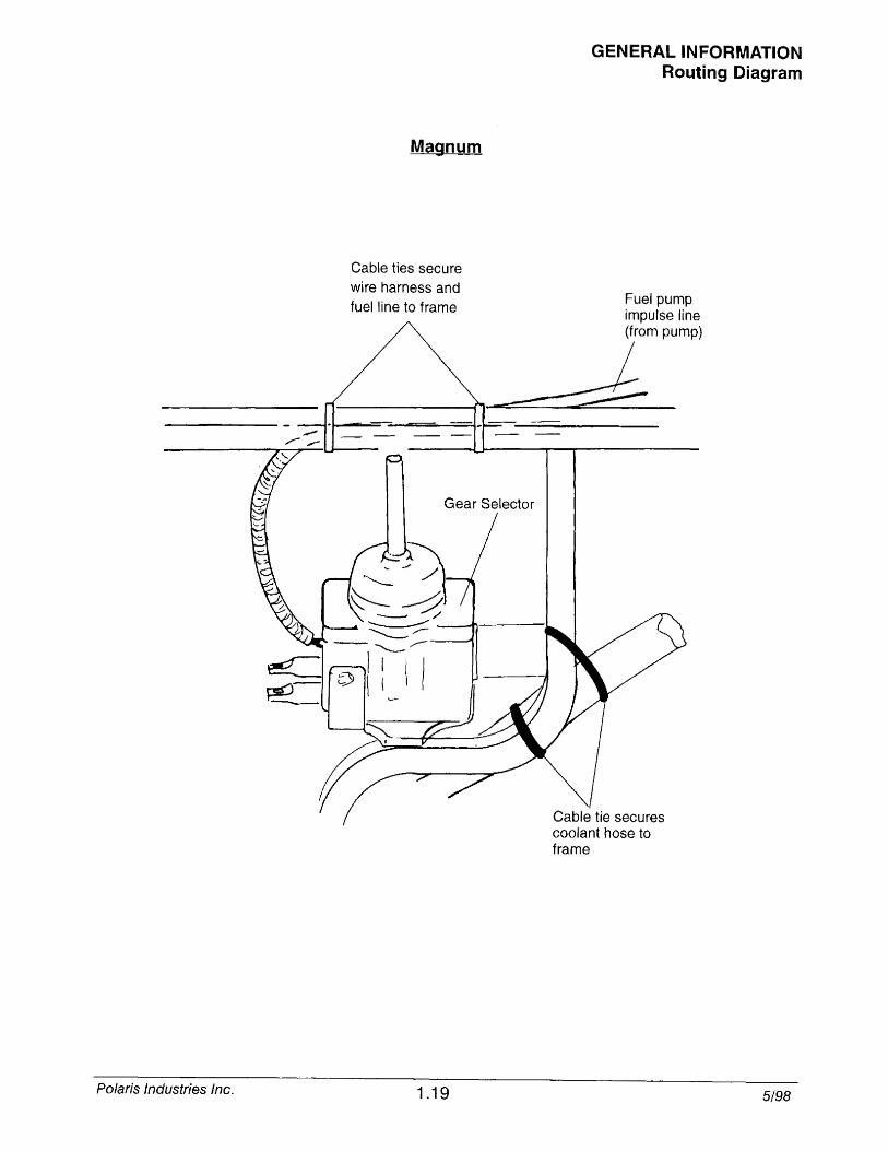
Magnum
Cable ties secure wire harness and fuel line to frame
1.19
GENERAL INFORMATION Routing Diagram
Fuel pump impulse line (from pump)
~
Cable tie secures coolant hose to frame
5/98
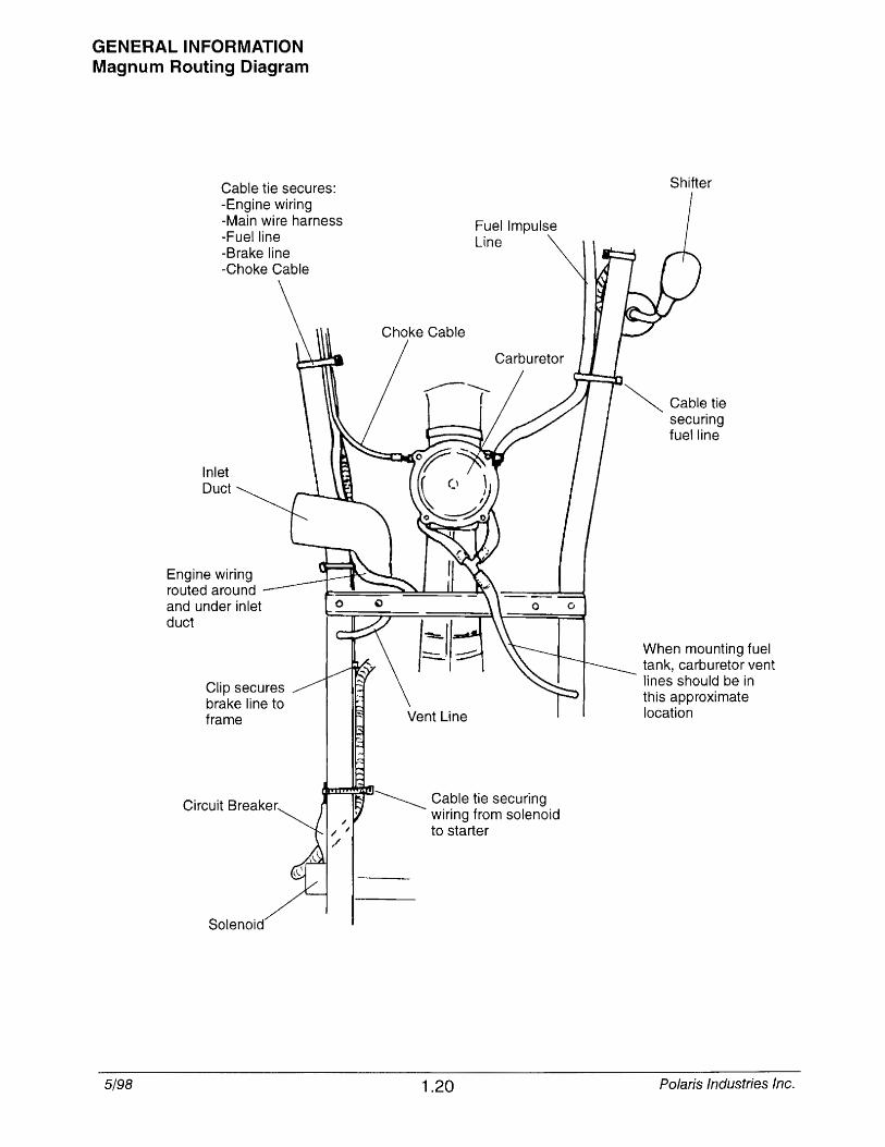
GENERAL INFORMATION Magnum Routing Diagram
5/98
Cable tie secures: -Engine wiring -Main wire harness -Fuel line -Brake line -Choke Cable
Inlet Duct
Engine wiring routed around and under inlet duct
Clip secures brake line to frame
Circuit Breaker Cable tie securing wiring from solenoid to starter
1.20
Shifter
~ Cable tie securing fuel line
When mounting fuel tank, carburetor vent lines should be in this approximate location
Polaris Industries Inc.
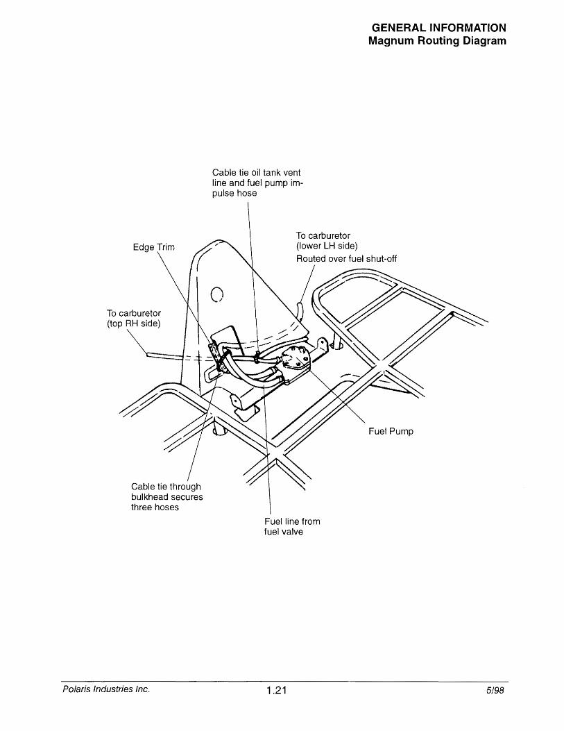
Edge Trim
To carburetor (top RH side)
Cable tie through bulkhead secures three hoses
Polaris Industries Inc.
Cable tie oil tank vent line and fuel pump impulse hose
To carburetor (lower LH side)
Fuel line from fuel valve
1.21
GENERAL INFORMATION Magnum Routing Diagram
Fuel Pump
5/98

GENERAL INFORMATION Hoses
5/98
Loosely cable tie
wire
Coolant bottle
400s
/ Front
~ Coolant hose
~ Convoluted tubing
1.22
Loosely cable tie Brake line Oil line Coolant line
~ Front
Polaris Industries Inc.

Raised side of reinforcement ribs face engine
Front ~
GENERAL INFORMATION 300 Fan Motor Wiring
Orient fan motor so wiring and vent line are on bottom.
Fan motor vent line should come straight up from motor between the two large coolant lines, through cab assembly and back down into frame as shown.
Polaris Industries Inc.
oil tank \,~~
-- J((~ 3\-\C~~/
I ~
~ 1.23
o
5/98
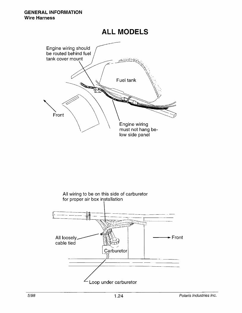
GENERAL INFORMATION Wire Harness
Engine wiring should be routed behind fuel tank cover mount
~~ Front
ALL MODELS
Fuel tank
Engine wiring must not hang below side panel
All wiring to be on this side of carburetor for proper air box installation
All loosely ________ cable tied
--.... Front
-----7--.1'-/ , ... -
Z under carburetor
5/98 1.24 Polaris Industries Inc.
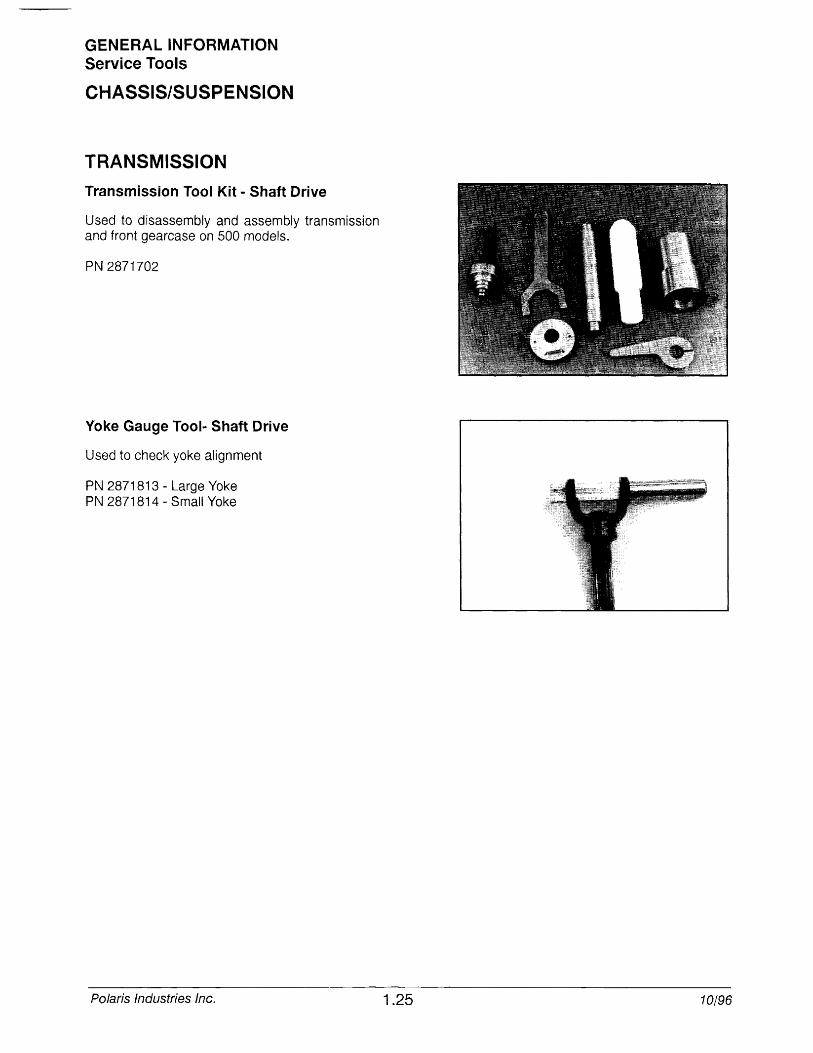
GENERAL INFORMATION Service Tools
CHASSIS/SUSPENSION
TRANSMISSION
Transmission Tool Kit - Shaft Drive
Used to disassembly and assembly transmission and front gearcase on 500 models.
PN 2871702
Yoke Gauge Tool .. Shaft Drive
Used to check yoke alignment
PN 2871813 - Large Yoke PN 2871814 - Small Yoke
Polaris Industries Inc. 1.25 10/96
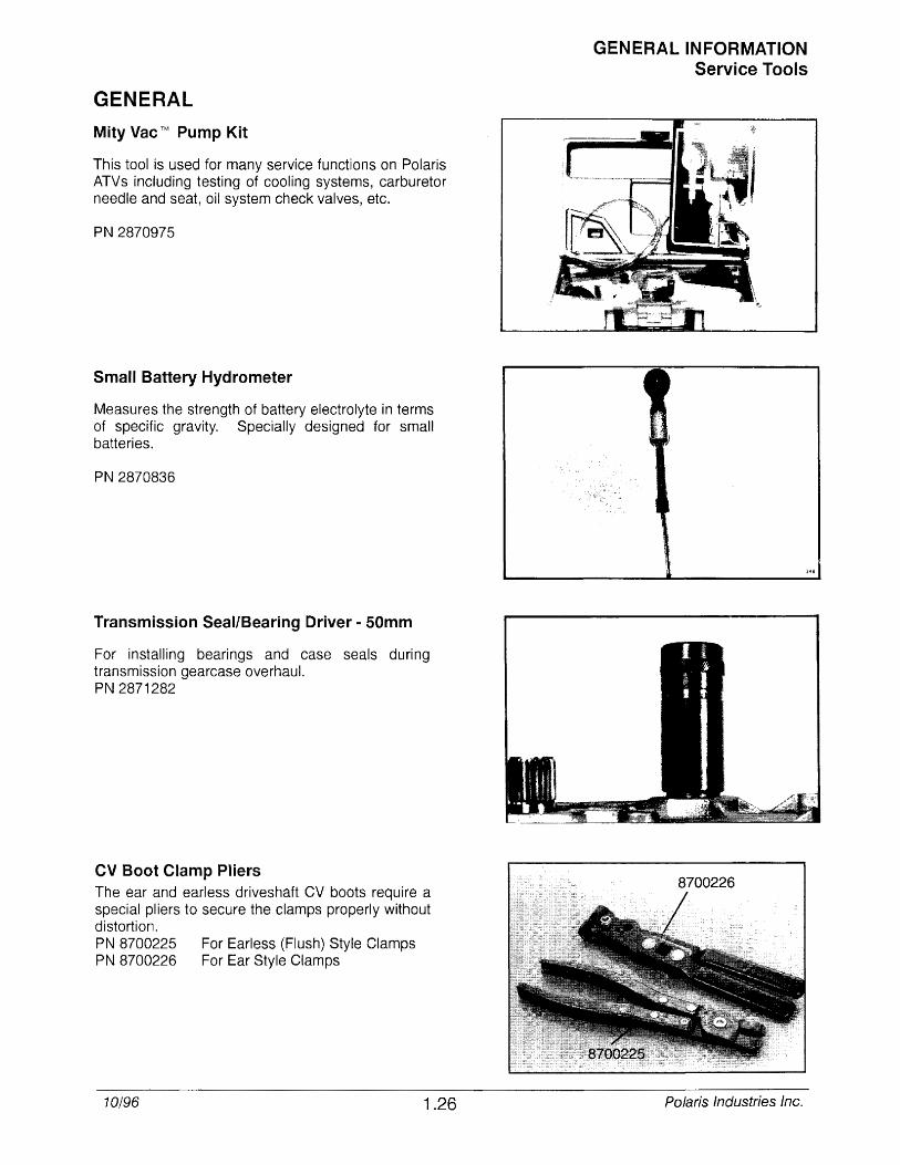
GENERAL
Mity Vac ™ Pump Kit
This tool is used for many service functions on Polaris ATVs including testing of cooling systems, carburetor needle and seat, oil system check valves, etc.
PN 2870975
Small Battery Hydrometer
Measures the strength of battery electrolyte in terms of specific gravity. Specially designed for small batteries.
PN 2870836
Transmission Seal/Bearing Driver - 50mm
For installing bearings and case seals during transmission gearcase overhaul. PN 2871282
CV Boot Clamp Pliers The ear and earless driveshaft CV boots require a special pliers to secure the clamps properly without distortion. PN 8700225 For Earless (Flush) Style Clamps PN 8700226 For Ear Style Clamps
10/96 1.26
GENERAL INFORMATION Service Tools
Polaris Industries Inc.
LIMITED WARRANTY
GENERAL INFORMATION Warranty
Polaris Industries Inc., 1225 Highway 169 North, Minneapolis, Minnesota 55441-5078, gives a SIX MONTH LIMITED WARRANTY on all components of the Polaris All Terrain Vehicle (ATV) against defects in material or workmanship. This warranty covers the parts and labor charges for repair or replacement of defective parts which are covered by this warranty. This warranty begins on the date of purchase. This warranty is transferrable to another consumer during the warranty period through a Polaris dealer. There is a charge of $25.00 payable to Polaris Industries Inc.
REGISTRATION At the time of sale, the Warranty Registration Form must be completed by your dealer and submitted to Polaris within ten days. Upon receipt of this registration, Polaris will record the registration for warranty. THE PURCHASER MUST COMPLETE AN ATV SAFETY TRAINING COURSE PROVIDED BY THE DEALER IN ORDER TO HAVE VALID WARRANTY ON THE ATV. No verification of registration will be sent to the purchaser as the copy of the Warranty Registration Form will be the warranty entitlement. If you have not signed the original registration and received the "customer copy", please contact your dealer immediately. NO WARRANTY COVERAGE WILL BE ALLOWED UNLESS YOUR ATV IS REGISTERED WITH POLARIS.
Initial dealer preparation and set-up of your ATV is very important in ensuring trouble-free operation. Purchasing a machine in the crate or without proper dealer set-up will void your warranty coverage.
WARRANTY COVERAGE AND EXCLUSIONS: LIMITATIONS OF WARRANTIES AND REMEDIES The Polaris limited warranty excludes any failures that are not caused by a defect in material or workmanship. This warranty does not cover accidental damage, normal wear and tear, abuse or improper handling. This warranty also does not cover any ATV that has been altered structurally, modified, neglected, improperly maintained, used for racing, or used for purposes other than for which it was manufactured, or for any damages which occur during trailer transit or as a result of unauthorized service orthe use of unauthorized parts. In addition, this warranty does not cover physical damage to paint or finish, stress cracks, tearing or puncturing of upholstery material, corrosion, or defects in parts, components or the ATV due to fire, explosions or any other cause beyond Polaris' control.
This warranty does not cover the use of unauthorized lubricants, chemicals, or fuels that are not compatible with the ATV. The exclusive remedy for breach of this warranty shall be, at Polaris' exclusive option, repair or replacement of any defective materials, or components or products. THE REMEDIES SET FORTH IN THIS WARRANTY ARE THE ONLY REMEDIES AVAILABLE TO ANY PERSON FOR BREACH OF THIS WARRANTY. POLARIS SHALL HAVE NO LIABILITY TO ANY PERSON FOR INCIDENTAL, CONSEQUENTIAL OR SPECIAL DAMAGES OF ANY DESCRIPTION, WHETHER ARISING OUT OF EXPRESS OR IMPLIED
WARRANTY OR ANY OTHER CONTRACT, NEGLIGENCE, OR OTHER TORT OR OTHERWISE. Some states do not permit the exclusion or limitation of incidental or consequential damages or implied warranties, so the above limitations or exclusions may not apply to you if inconsistent with controlling state law.
ALL IMPLIED WARRANTIES (INCLUDING BUT NOT LIMITED TO THE IMPLIED WARRANTIES OF MERCHANTABILITY AND FITNESS FOR A PARTICULAR PURPOSE) ARE LIMITED IN DURATION TO THE ABOVE SIX MONTH WARRANTY PERIOD. POLARIS FURTHER DISCLAIMS ALL EXPRESS WARRANTIES NOT STATED IN THIS WARRANTY. Some states do not allow limitations on how long an implied warranty lasts, so the above limitation may not apply to you if inconsistent with controlling state law.
HOW TO OBTAIN WARRANTY SERVICE
If your ATV requires warranty service, you must take it to a Polaris Servicing Dealer. When requesting warranty service you must present your copy of the Warranty Registration form to the dealer. (THE COST OF TRANSPORTATION TO AND FROM THE DEALER IS YOUR RESPONSIBILITY). Polaris suggests that you use your original selling dealer; however, you may use any Polaris Servicing Dealer to perform warranty service.
Please work with your dealer to resolve any warranty issues. Should your dealer require any additional assistance they will contact the appropriate person at Polaris.
This warranty gives you specific legal rights, and you may also have other rights which vary from state to state.
If any of the above terms are void because of state or federal law, all other warranty terms will remain in effect.
Engine Oil
1. Always use Polaris engine oil.
2. Never substitute or mix oil brands as serious engine damage and voiding of warranty can result.
Polaris Industries Inc. 1.27 7/96
GENERAL INFORMATION Glossary Of Terms ABOC: After bottom dead center. ACV: Alternating current voltage. Alternator: Electrical generator producing voltage alternating current. ATDC: After top dead center. BBDC: Before bottom dead center. BDC: Bottom dead center. BTOC: Before top dead center. CC: Cubic centimeters. COl: Capacitor discharge ignition. Ignition system which stores voltage generated by the stator plate exciter coil in a capacitor or condenser (in COl box). At the proper moment a voltage generated by the stator plate pulser coil closes an electronic switch (thyristor) in the COl box and allows the voltage in the capacitor to discharge into the primary windings of the ignition coil. Center Distance: Distance between center of crankshaft and center of driven clutch shaft. Chain Pitch: Distance between chain link pins (No. 35 = 3/8" or 1 cm). Polaris measures chain length in number of pitches. CI: Cubic inches.
Clutch Buttons: Plastic bushings which transmit rotation of the clutch to the movable sheave in the drive and driven clutch. Clutch Offset: Drive and driven clutches are offset so that drive belt will stay nearly straight as it moves along the clutch face. Clutch Weights: Three levers in the drive clutch which relative to their weight, profile and engine RPM cause the drive clutch to close. Condenser/Capacitor: A storage reservoir for electricity, used in both E.T. and COl systems. Crankshaft Run-Out: Run-out or "bend" at crankshaft measured with a dial indicator while crankshaft is supported between centers on V blocks or resting in lower half of crankcase. Measure at various pOints especially at PTO. Maximum allowable run-out is .006" (.02 cm). Dev: Direct current voltage. Detonation: The spontaneous ignition of the unburned fuel/air mixture after normal spark ignition. Piston looks "hammered" through, rough appearance around hole. Possible causes: 1) too high a compression ratio for the fuel octane; 2) low octane fuel; 3) over-advanced ignition timing. Dial Bore Gauge: A cylinder measuring instrument which uses a dial indicator. Good for showing taper and out-at-round in the cylinder bore. Electrical Open: Open circuit. An electrical circuit which isn't complete. (i.e. poor connections or broken wire at hi-Io beam switch resulting in loss of headlights. Electrical Short: Short circuit. An electrical circuit which is completed before the current reaches the intended component. (i.e. a bare wire touching the snowmobile chassis under the seat resulting in loss of taillights and brake lights). End Seals: Rubber seals at each end of the crankshaft. Engagement RPM: Engine RPM at which the drive clutch engages to make contact with the drive belt. ft.: Foot/feet. Foot Pound: Ft. lb. A force of one pound at the end of a lever one foot in length, applied in a rotational direction. g: Gram. Unit of weight in the metric system. gal.: Gallon. Head Volume: Cylinder head capacity in cc, head removed from engine with spark plug installed. High Tension Lead: The heavy insulated wire which carries the high secondary voltage from the coil to the spark plug. Holed Piston: Piston in which a hole has formed on the dome. Possible causes: 1) detonation; 2) pre-ignition. HP: Horsepower.
10: Inside diameter. Ignition Coil: A type of transformer which increases voltage in the primary windings (approx. 200V) to a higher voltage in the secondary windings (approx. 14KV - 32KV) through inductions. Secondary voltage is high enough to arc the air gap at the spark plug. Ignition Generating Coil: Exciter coil, primary charge coil. Stator plate coil which generates primary ignition voltage. in.: Inch/inches. Inch Pound: In. lb. 12 in. Ibs. = 1 ft. lb.
7/96 1.28 Polaris Industries Inc.
kg/cm 2 : Kilograms per square centimeter. kg-m: Kilogram meters.
GENERAL INFORMATION Glossary Of Terms
Kilogram/meter: A force of one kilogram at the end of a lever one meter in length, applied in a rotational direction. I or Itr: Liter.
2 Ibs/in : Pounds per square inch.
Left Side: Always referred to based on normal operating position of the driver. m: Meter/meters. Mag: Magneto.
Magnetic Induction: As a conductor (coil) is moved through a magnetic field, a voltage will be generated in the windings. This is how mechanical energy in our engines is converted to electrical energy in the lighting coil, ignition generating coils and trigger coil. mi.: Mile/miles.
mm: Millimeter. Unit of length in the metric system. 1 mm = .040". N-m: Newton meters. 00: Outside diameter. Ohm: The unit of electrical resistance opposing current flow. oz.: Ounce/ounces. Piston Clearance: Total distance between piston and cylinder wall. Piston Erosion: Piston dome melts. Usually occurs at the exhaust port area. Possible causes: 1) lean fuel/air mixture; 2) improper spark plug heat range. Pre-Ignition: A problem in combustion where the fuel/air mixture is ignited before normal spark ignition. Piston looks melted at area of damage. Possible causes: 1) too hot a spark plug; 2) spark plug not properly torqued; 3) "glowing" piece of head gasket, metal burr or carbon in the combustion chamber; 4) lean fuel/air mixture. Primary Circuit: This circuit is responsible for the voltage build up in the COl capacitor. In the COl system the parts include the exciter coil, the trigger coil, the wires from stator plate to COl box and to the low resistance primary windings in the ignition coil. Primary Clutch: Drive clutch on engine. psi.: Pounds per square inch. PTO: Power take off. PVT: Polaris Variable Transmission (Drive Clutch System) qt.: Quart/quarts. RPM: Revolutions per minute. Resistance: In the mechanical sense, friction or load. In the electrical sense, ohms. Both result in energy conversion to heat. Right Side: Always referred to based on normal operating position of the driver. RPM: Revolutions per minute. Running Time: Ignition timing when fully advanced or at specified RPM. Secondary Circuit: This circuit consists ofthe large secondary coil windings, high tension wire and ground through the spark plug air gap. Secondary Clutch: Driven clutch on chaincase or jackshaft. Seized Piston: Galling of the sides of a piston. Usually there is a transfer of aluminum from the piston onto the cylinder wall. Possible causes: 1) improper lubrication; 2) excessive temperatures; 3) insufficient piston clearance; 4) stuck piston rings. Select Monitor: Diagnostic tool which provides static and dynamic displays of the function of critical components in an EFI system. It also has the capability to display the contents of the ECU memory. Spark Plug Reach: Length of threaded portion of spark plug. Polaris uses 3/4/1 (2 cm) reach plugs. Static Timing: Ignition timing when engine is at zero RPM. Stator Fiate: The plate mounted under the flywheel supporting the primary ignition components and lighting coil. Surge Tank: The fill tank in the liquid cooling system.
Polaris Industries Inc. 1.29 7/96
GENERAL INFORMATION Glossary Of Terms TOC: Top dead center. Piston's most outward travel from crankshaft. Trigger Coil: Pulser coil. Generates the voltage for triggering (closing) the thyristor and timing the spark in COl systems. Small coil mounted at the top of the stator plate next to the ignition generating coil. V Regulator: Voltage regulator. Maintains maximum lighting coil output at approx. 14.5 ACV as engine RPM increases. Venturi: An area of air constriction. A venturi is used in carburetors to speed up air flow which lowers pressure in venturi to below atmospheric pressure, causing fuel to be pushed through jets, etc., and into the venturi to be mixed with air and form a combustible air/fuel mixture. Volt: The unit of measure for electrical pressure of electromotive force. Measured by a voltmeter in parallel with the circuit. Watt: Unit of electrical power. Watts = amperes x volts. waT: Wide open throttle.
7/96 1.30 Polaris Industries Inc.
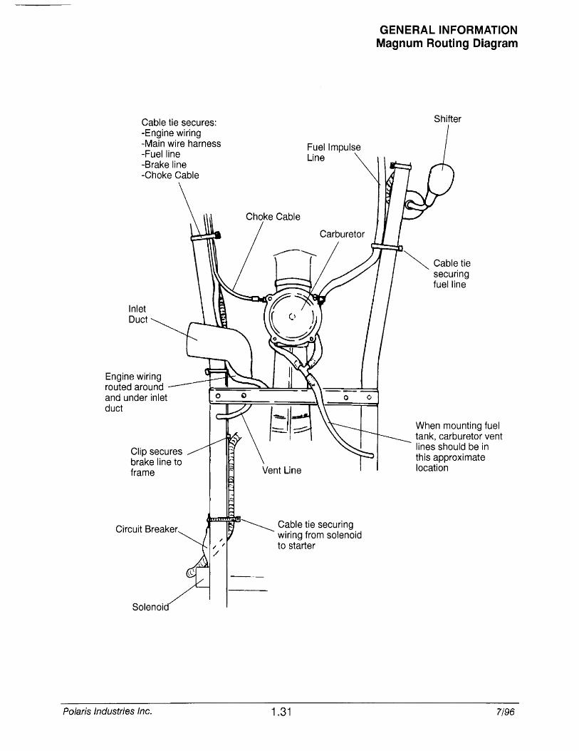
Cable tie secures: -Engine wiring -Main wire harness -Fuel line -Brake line -Choke Cable
Inlet Duct
Engine wiring routed around and under inlet duct
Clip secures brake line to frame
Solenoid
Polaris Industries Inc.
Choke Cable
Fuel Impulse Line
~ Cable tie securing wiring from solenoid to starter
1.31
GENERAL INFORMATION Magnum Routing Diagram
Shifter
~ Cable tie securing fuel line
When mounting fuel tank, carburetor vent lines should be in this approximate location
7/96
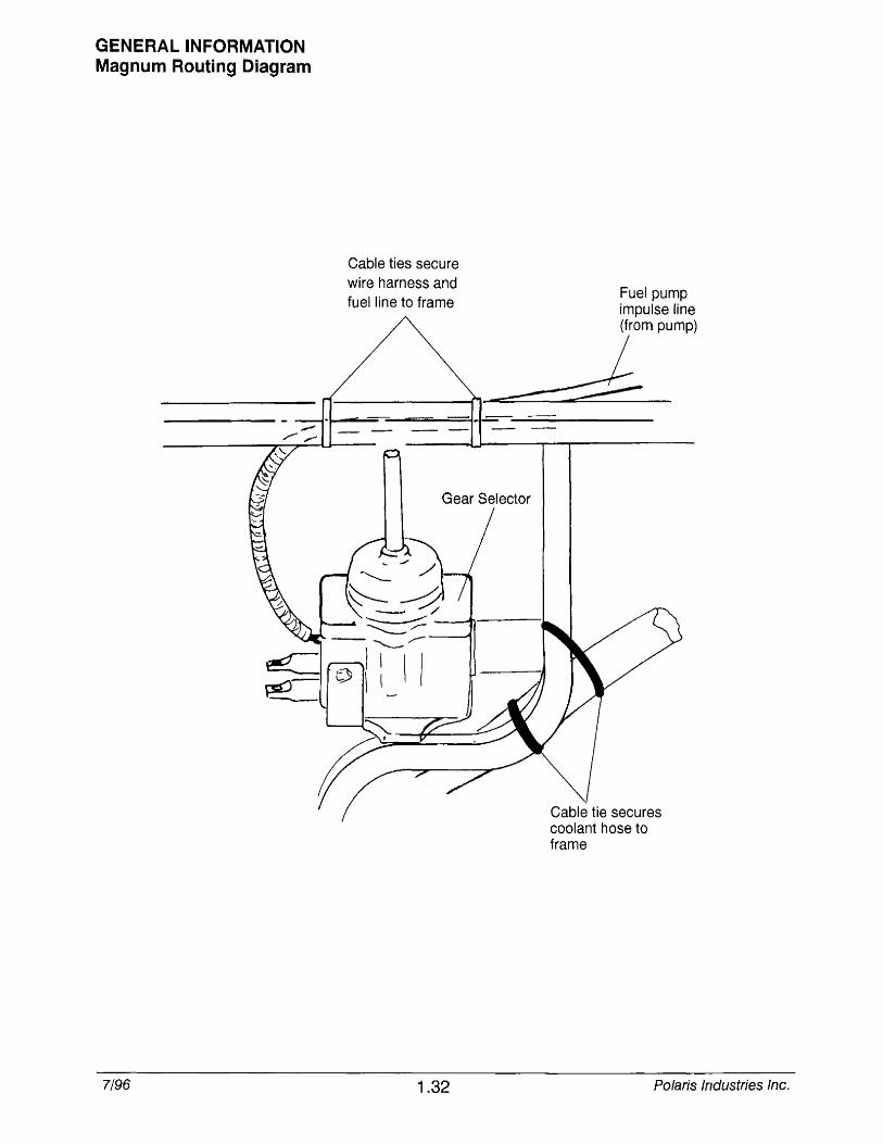
GENERAL INFORMATION Magnum Routing Diagram
7/96
Cable ties secure wire harness and fuel line to frame
Fuel pump impulse line (from pump)
~ Gear Selector
1.32
Cable tie secures coolant hose to frame
Polaris Industries Inc.

To carburetor (top RH side)
Cable tie through bulkhead secures three hoses
Polaris Industries Inc.
Cable tie oil tank vent line and fuel pump impulse hose
To carburetor (lower LH side)
GENERAL INFORMATION Magnum Routing Diagram
Routed over fuel shut-off
Fuel line from fuel valve
1.33 7/96
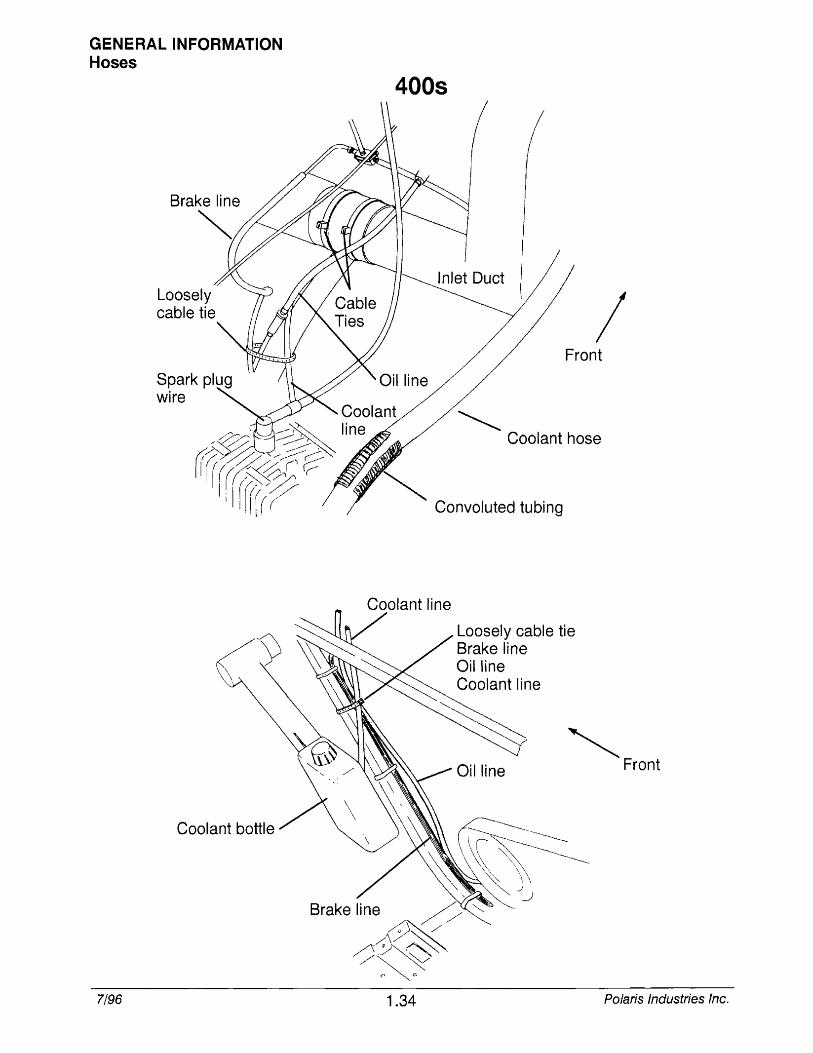
GENERAL INFORMATION Hoses
7/96
Loosely cable tie
Coolant bottle
4008
Inlet Duct \
/ Front
~ Coolant hose
~ Convoluted tubing
Loosely cable tie Brake line Oil line Coolant line
'" Front
Brake line ~ ""-y~'
/)~~ ~~
1.34 Polaris Industries Inc.
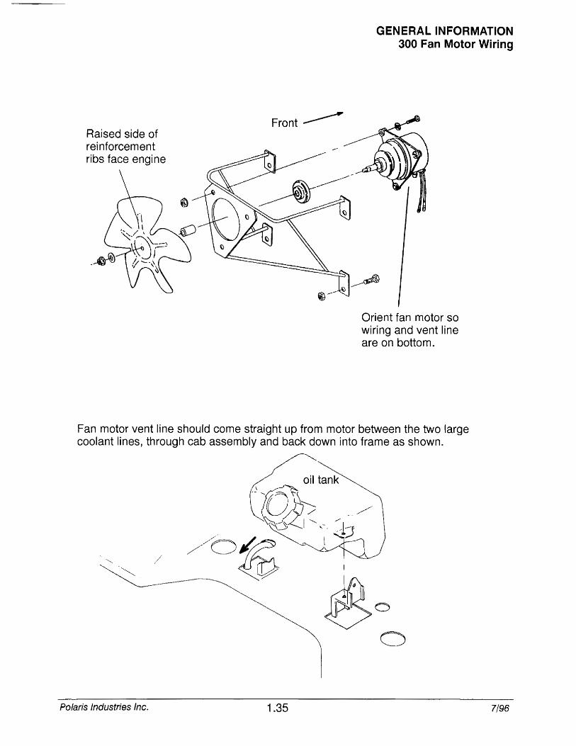
Raised side of rei nforcem ent ribs face engine
Front~
GENERAL INFORMATION 300 Fan Motor Wiring
Orient fan motor so wiring and vent line are on bottom.
Fan motor vent line should come straight up from motor between the two large coolant lines, through cab assembly and back down into frame as shown.
Polaris Industries Inc. 1.35 7/96
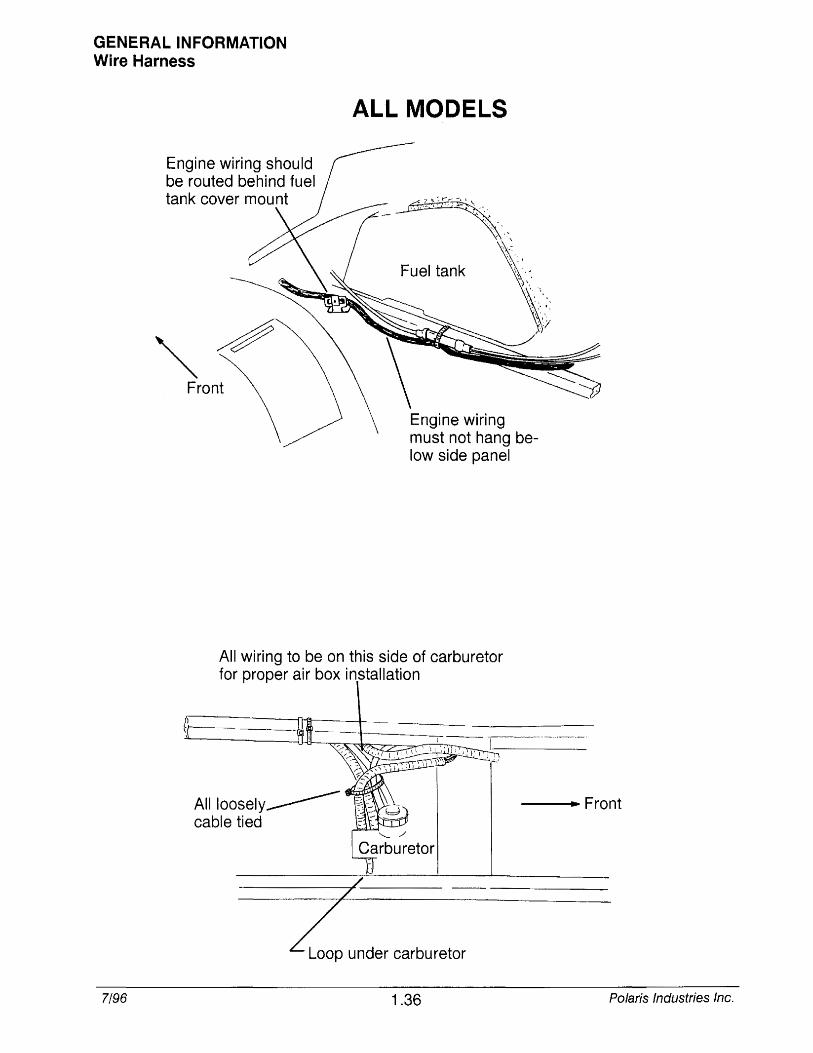
GENERAL INFORMATION Wire Harness
Engine wiring should be routed behind fuel tank cover mou nt
""~ Front
ALL MODELS
-- "'",
.'
~;,':~-:"'\' ".
~"
Fuel tank \< . . \.,.,\,
. :. ~, \ . '. "~'I ,'Y
Engine wiring must not hang below side panel
All wiring to be on this side of carburetor for proper air box installation
Ailioosely ________ cable tied
--....... Front
7/96
/ -----7~----
Z under carburetor
1.36 Polaris Industries Inc.
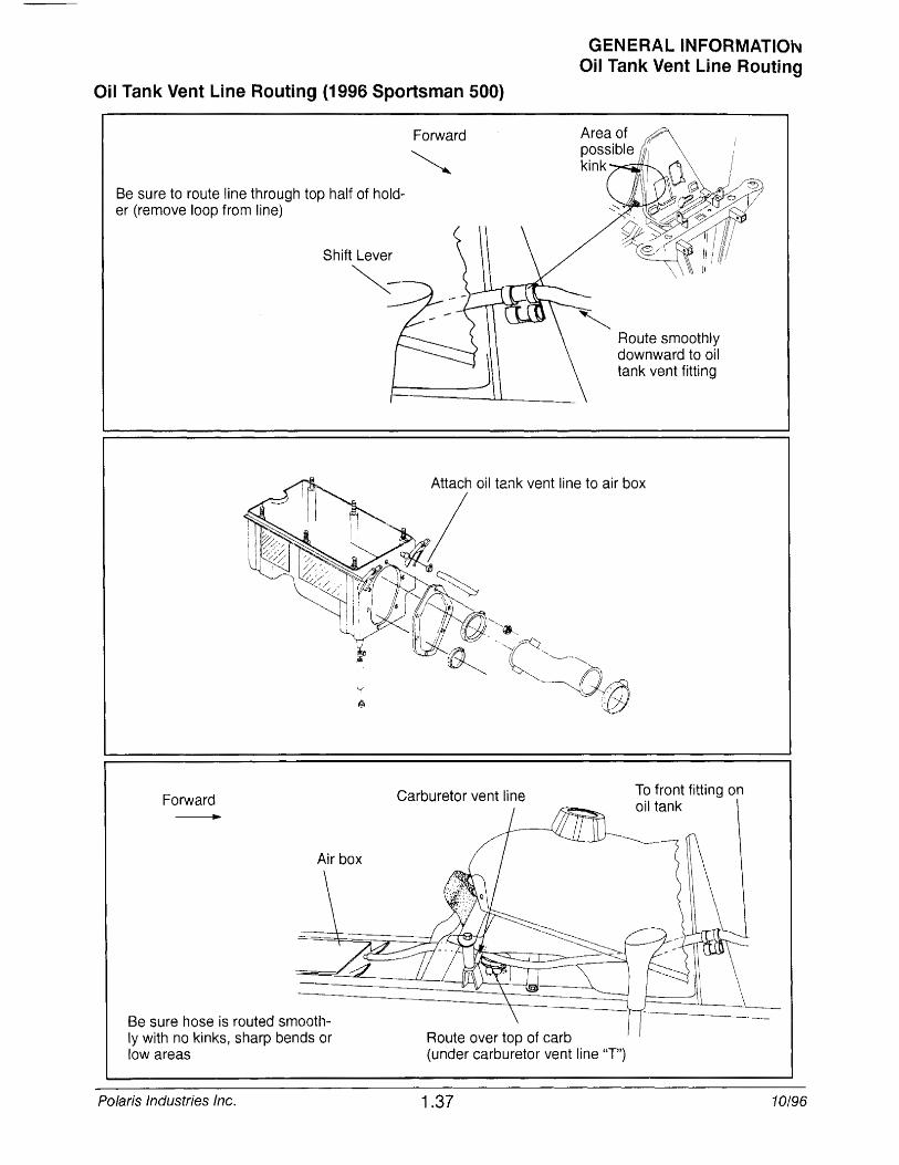
Oil Tank Vent Line Routing (1996 Sportsman 500)
Be sure to route line through top half of holder (remove loop from line)
Forward
Forward Carburetor vent line II
Route over top of carb
GENERAL INFORMATION Oil Tank Vent Line Routing
" Route smoothly downward to oil tank vent fitting
To front fitting on oil tank
Be sure hose is routed smoothly with no kinks, sharp bends or low areas (under carburetor vent line "T")
Polaris Industries Inc. 1.37 10/96

CHAPTER 2 MAINTENANCE
Periodic Maintenance Chart .................... 2.1-2.2
Pre-Ride Inspection ........................... 2.2
Recommended Lubricants and Capacities ....... 2.3
Lubricant and Maintenance Product Numbers .... 2.4
Lubrication Chart ............................. 2.5-2.9
Front Gearcase Lubrication .................... 2.10
Carburetor Adjustments ....................... 2.11-2.12b
Carburetor Draining ........................... 2.13-2.14
Breather System Maintenance ................. 2.14a-2.14b
Compression Test ............................ 2.15
Battery Maintenance .......................... 2.16
General Maintenance ......................... 2.17
Coolant System Maintenance .................. 2.18
2 Stroke Engine Maintenance .................. 2.19-2.22d
4 Stroke Engine Maintenance .................. 2.22e-2.29
Toe Alignment Inspection ...................... 2.30
Chassis Maintenance ......................... 2.31-2.45
Drive Chain Inspection/Adjustment .............. 2.36-2.39
Drive Chain Adjustment, Concentric SWingarm ... 2.37a

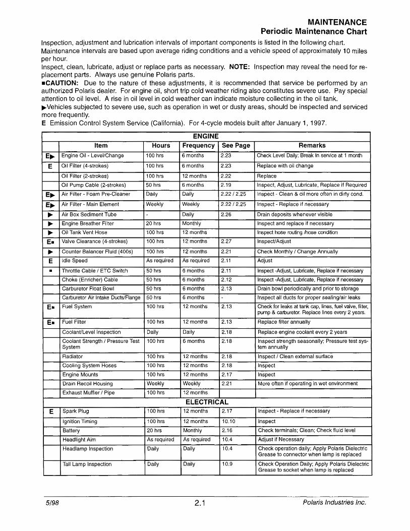
MAINTENANCE Periodic Maintenance Chart
Inspection, adjustment and lubrication intervals of important components is listed in the following chart. Maintenance intervals are based upon average riding conditions and a vehicle speed of approximately 10 miles per hour. Inspect, clean, lubricate, adjust or replace parts as necessary. NOTE: Inspection may reveal the need for replacement parts. Always use genuine Polaris parts. -CAUTION: Due to the nature of these adjustments, it is recommended that service be periormed by an authorized Polaris dealer. For engine oil, short trip cold weather riding also constitutes severe use. Pay special attention to oil level. A rise in oil level in cold weather can indicate moisture collecting in the oil tank . .... Vehicles subjected to severe use, such as operation in wet or dusty areas, should be inspected and serviced more frequently. E Emission Control System Service (California). For 4-cycle models built after January 1, 1997.
ENGINE Item Hours Frequency See Page Remarks
E .... Engine Oil - Level/Change 100 hrs 6 months 2.23 Check Level Daily; Break In service at 1 month
E Oil Filter (4-strokes) 100 hrs 6 months 2.23 Replace with oil change
Oil Filter (2-strokes) 100 hrs 12 months 2.22 Replace
Oil Pump Cable (2-strokes) 50 hrs 6 months 2.19 Inspect, Adjust, Lubricate, Replace if Required
E .... Air Filter - Foam Pre-Cleaner Daily Daily 2.22/2.25 Inspect Clean & oil more often in dirty condo
E .... Air Filter - Main Element Weekly Weekly 2.22/2.25 Inspect - Replace if necessary
.... Air Box Sediment Tube Daily 2.26 Drain deposits whenever visible
.... Engine Breather Filter 20 hrs Monthly Inspect and replace if necessary
.... Oil Tank Vent Hose 100 hrs 12 months Inspect hose routing /hose condition
E. Valve Clearance (4-strokes) 100 hrs 12 months 2.27 Inspect/Adjust
.... Counter Balancer Fluid (400s) 100 hrs 12 months 2.21 Check Monthly / Change Annually
E Idle Speed As required As required 2.11 Adjust
• Throttle Cable / ETC Switch 50 hrs 6 months 2.11 Inspect -Adjust, Lubricate, Replace if necessary
Choke (Enricher) Cable 50 hrs 6 months 2.12 Inspect -Adjust, Lubricate, Replace if necessary
Carburetor Float Bowl 50 hrs 6 months 2.13 Drain bowl periodically and prior to storage
Carburetor Air Intake Ducts/Flange 50 hrs 6 months - Inspect all ducts for proper sealing/air leaks
E. Fuel System 100 hrs 12 months 2.13 Check for leaks at tank cap, lines, fuel valve, filter, pump & carburetor. Replace lines every 2 years.
E- Fuel Filter 100 hrs 12 months 2.13 Replace filter annually
Coolant/Level Inspection Daily Daily 2.18 Replace engine coolant every 2 years
Coolant Strength / Pressure Test 100 hrs 6 months 2.18 Inspect strength seasonally: Pressure test sys-System tem annually
Radiator 100 hrs 12 months 2.18 Inspect / Clean external surface
Cooling System Hoses 100 hrs 12 months 2.18 Inspect
Engine Mounts 100 hrs 12 months 2.17 Inspect
Drain Recoil Housing Weekly Weekly 2.21 More often if operating in wet environment
Exhaust Muffler I Pipe 100 hrs 12 months
ELECTRICAL
E Spark Plug 100 hrs 12 months 2.17 Inspect - Replace if necessary
Ignition Timing 100 hrs 12 months 10.10 Inspect
Battery 20 hrs Monthly 2.16 Check terminals; Clean; Check fluid level
Headlight Aim As required As required 10.4 Adjust if Necessary
Headlamp Inspection Daily Daily 10.4 Check operation daily; Apply Polaris Dielectric Grease to connector when lamp is replaced
Tail Lamp Inspection Daily Daily 10.9 Check Operation Daily; Apply Polaris Dielectric Grease to socket when lamp is replaced
5/98 2.1 Polaris Industries Inc.
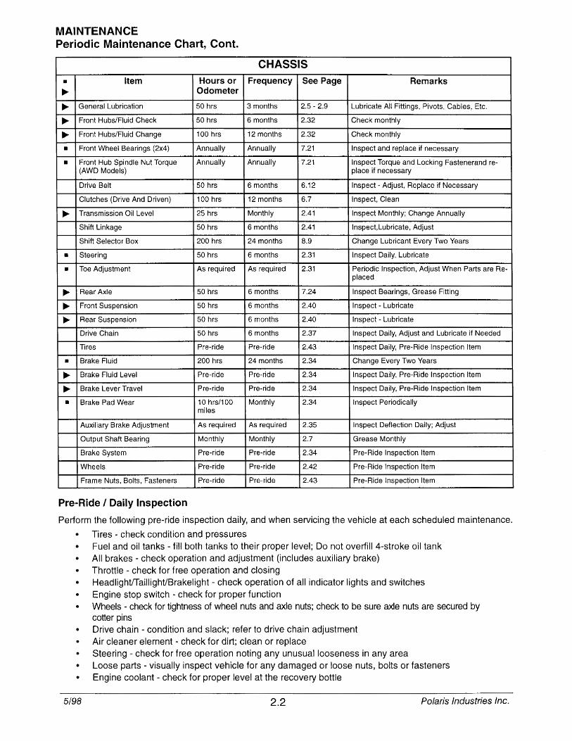
MAINTENANCE Periodic Maintenance Chart, Cont.
CHASSIS
• Item Hours or Frequency See Page Remarks ..... Odometer
..... General Lubrication 50 hrs 3 months 2.5 - 2.9 Lubricate All Fittings, Pivots, Cables, Etc.
..... Front Hubs/Fluid Check 50 hrs 6 months 2.32 Check monthly
..... Front Hubs/Fluid Change 100 hrs 12 months 2,32 Check monthly
• Front Wheel Bearings (2x4) Annually Annually 7.21 Inspect and replace if necessary
• Front Hub Spindle Nut Torque Annually Annually 7.21 Inspect Torque and Locking Fastenerand re-(AWD Models) place if necessary
Drive Belt 50 hrs 6 months 6.12 Inspect - Adjust, Replace if Necessary
Clutches (Drive And Driven) 100 hrs 12 months 6.7 Inspect, Clean
..... Transmission Oil Level 25 hrs Monthly 2.41 Inspect Monthly; Change Annually
Shift Linkage 50 hrs 6 months 2.41 Inspect, Lubricate, Adjust
Shift Selector Box 200 hrs 24 months 8.9 Change Lubricant Every Two Years
• Steering 50 hrs 6 months 2.31 Inspect Daily, Lubricate
• Toe Adjustment As required As required 2.31 Periodic Inspection, Adjust When Parts are Re-placed
..... Rear Axle 50 hrs 6 months 7.24 Inspect Bearings, Grease Fitting
..... Front Suspension 50 hrs 6 months 2.40 Inspect - Lubricate
..... Rear Suspension 50 hrs 6 months 2.40 Inspect - Lubricate
Drive Chain 50 hrs 6 months 2.37 Inspect Daily, Adjust and Lubricate if Needed
Tires Pre-ride Pre-ride 2.43 Inspect Daily, Pre-Ride Inspection Item
• Brake Fluid 200 hrs 24 months 2.34 Change Every Two Years
..... Brake Fluid Level Pre-ride Pre-ride 2.34 Inspect Daily, Pre-Ride Inspection Item
..... Brake Lever Travel Pre-ride Pre-ride 2.34 Inspect Daily, Pre-Ride Inspection Item
• Brake Pad Wear 10 hrs/100 Monthly 2.34 Inspect Periodically miles
Auxiliary Brake Adjustment As required As required 2.35 Inspect Deflection Daily; Adjust
Output Shaft Bearing Monthly Monthly 2.7 Grease Monthly
Brake System Pre-ride Pre-ride 2.34 Pre-Ride Inspection Item
Wheels Pre-ride Pre-ride 2.42 Pre-Ride Inspection Item
Frame Nuts, Bolts, Fasteners Pre-ride Pre-ride 2.43 Pre-Ride Inspection Item
Pre-Ride I Daily Inspection
Perform the following pre-ride inspection daily, and when servicing the vehicle at each scheduled maintenance.
• Tires - check condition and pressures • Fuel and oil tanks - fill both tanks to their proper level; Do not overfill 4-stroke oil tank • All brakes - check operation and adjustment (includes auxiliary brake) • Throttle - check for free operation and closing
HeadlightfTaillightiBrakelight - check operation of all indicator lights and switches • Engine stop switch - check for proper function • Wheels - check for tightness of wheel nuts and axle nuts; check to be sure axle nuts are secured by
cotter pins • Drive chain - condition and slack; refer to drive chain adjustment
Air cleaner element - check for dirt; clean or replace Steering check for free operation noting any unusual looseness in any area Loose parts - visually inspect vehicle for any damaged or loose nuts, bolts or fasteners
• Engine coolant - check for proper level at the recovery bottle
5/98 2.2 Polaris Industries Inc.
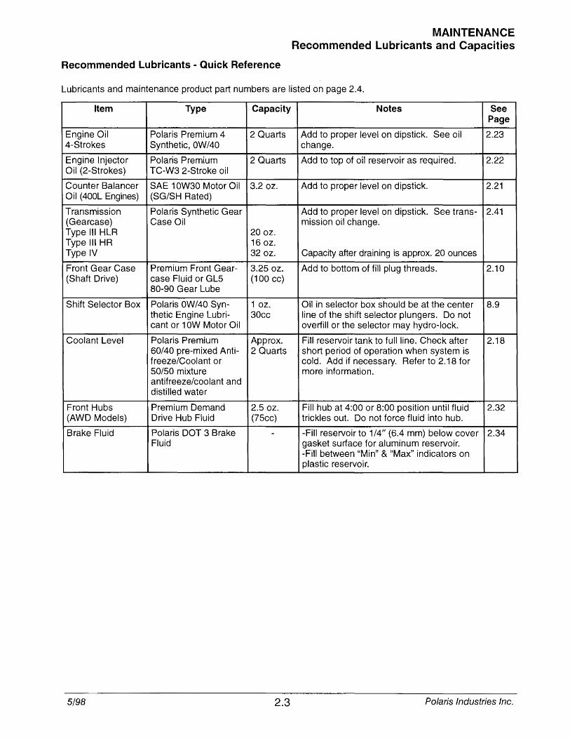
Recommended Lubricants - Quick Reference
MAINTENANCE Recommended Lubricants and Capacities
Lubricants and maintenance product part numbers are listed on page 2.4.
Item Type Capacity Notes See Page
Engine Oil Polaris Premium 4 2 Quarts Add to proper level on dipstick. See oil 2.23 4-Strokes Synthetic,OW/40 change.
Engine Injector Polaris Premium 2 Quarts Add to top of oil reservoir as required. 2.22 Oil (2-Strokes) TC-W3 2-Stroke oil
Counter Balancer SAE 10W30 Motor Oil 3.2 oz. Add to proper level on dipstick. 2.21 Oil (400L Engines) (SG/SH Rated)
Transmission Polaris Synthetic Gear Add to proper level on dipstick. See trans- 2.41 (Gearcase) Case Oil mission oil change. Type III HLR 20 oz. Type III HR 16 oz. Type IV 32 oz. Capacity after draining is approx. 20 ounces
Front Gear Case Premium Front Gear- 3.2S oz. Add to bottom of fill plug threads. 2.10 (Shaft Drive) case Fluid or GLS (100 cc)
80-90 Gear Lube
Shift Selector Box Polaris OW /40 Syn- 1 oz. Oil in selector box should be at the center 8.9 thetic Engine Lubri- 30cc line of the shift selector plungers. Do not cant or 10W Motor Oil overfill or the selector may hydro-lock.
Coolant Level Polaris Premium Approx. Fill reservoir tank to full line. Check after 2.18 60/40 pre-mixed Anti- 2 Quarts short period of operation when system is freeze/Coolant or cold. Add if necessary. Refer to 2.18 for SO/SO mixture more information. antifreeze/coolant and distilled water
Front Hubs Premium Demand 2.S oz. Fill hub at 4:00 or 8:00 position until fluid 2.32 (AWD Models) Drive Hub Fluid (7Scc) trickles out. Do not force fluid into hub.
Brake Fluid Polaris DOT 3 Brake - -Fill reservoir to 1/4" (6.4 mm) below cover 2.34 Fluid gasket surface for aluminum reservoir.
-Fill between "Min" & "Max" indicators on plastic reservoir.
5/98 2.3 Polaris Industries Inc.