Embed Size (px)
Citation preview
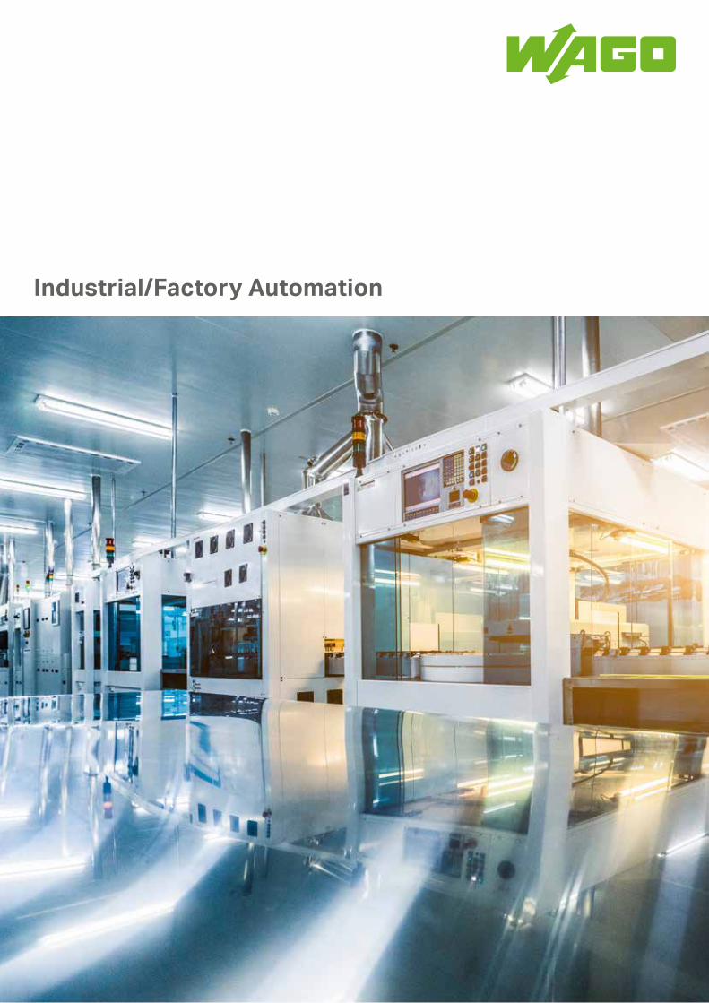
Industrial/Factory Automation

2
Contents
Energy Supply and Distribution with 04 TOPJOB® S Rail-Mount Terminal Blocks
Perfect Shielding 06
EPSITRON® – Advanced Power Supply System 08
Current and Energy Measurement 12
Flexibility without Additional Downtime 14
Safety for People and Machines 16
Easy Integration of Safety-Related Controllers 18
Universal, Compact and Economical – 20 the Ideal Fieldbus Node
Sensor and Actuator Boxes – 22 TOPJOB® S Sensor/Actuator Terminal Blocks
Fieldbus Couplers and Controllers – 24 IEC 61131-3 Engineering Software
Mechatronics Today – 26 e!COCKPIT for Modern Engineering
Embedded Linux® 28
The WAGO Tool Chain – from Planning to Commissioning 30
Industry 4.0 – the “Smart Factory” 32
Industry 4.0 – Adaptable Production Processes 34
Industry 4.0 – IT Security 36
Resources – Full Line Catalogs 38
3

ENERGY SUPPLY AND DISTRIBUTIONTOPJOB® S Rail-Mount Terminal Blocks with Push-in CAGE CLAMP® Reliability
The Safe and Flexible Rail-Mount Terminal Block System
In machine and equipment engineering, the focus is on meeting the automation challenge. Besides control technology and mechanical systems, having the proper electronic equip- ment in the control cabinet is also crucial. In order to implement safe energy and signal distribution, consistency, speed and flexibility must be in the foreground.
The push-in technology in the TOPJOB® S Rail-Mount Terminal Blocks leaves nothing to be desired. All conductor cross-sections from 0.14 mm² to 185 mm² (24 AWG–350 kcmil) are covered.
Consistent and rapid marking increases efficiency, giving you more time to tackle the automation challenge.
4
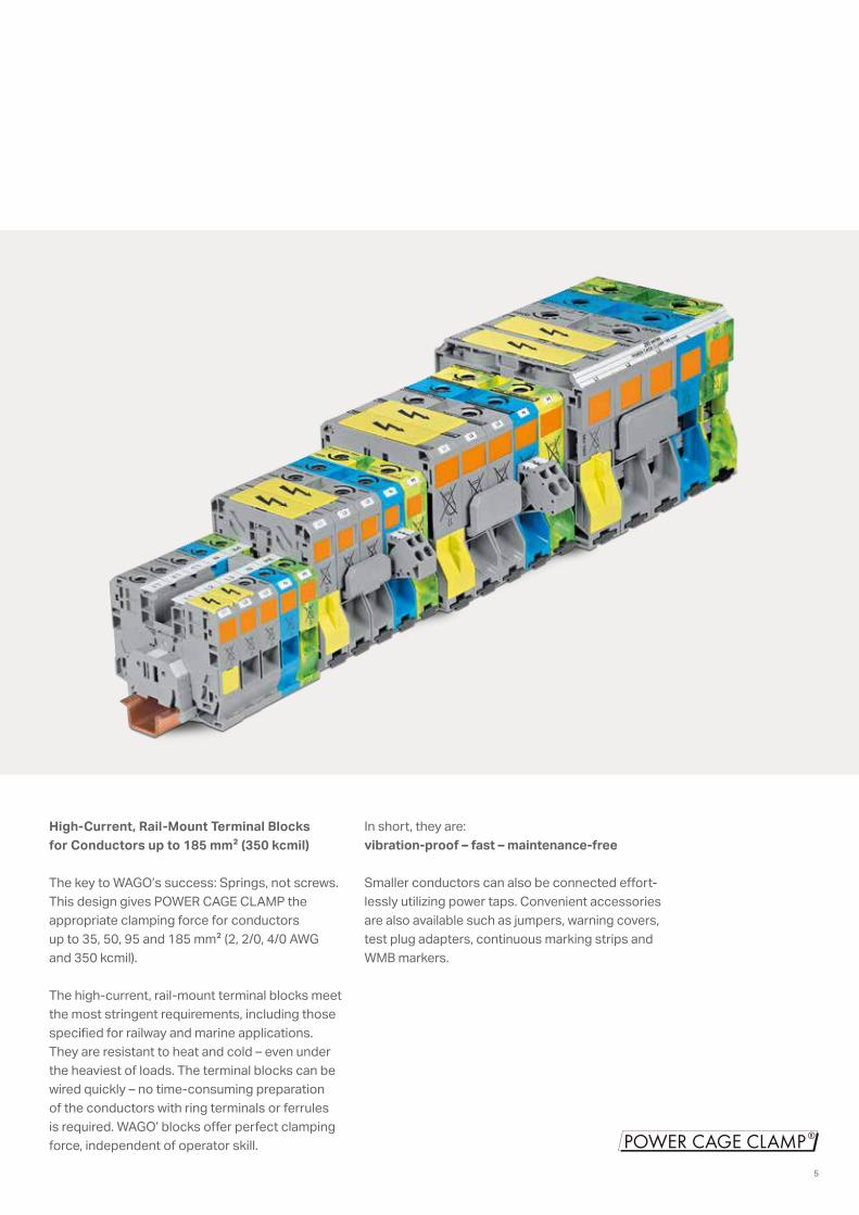
High-Current, Rail-Mount Terminal Blocks for Conductors up to 185 mm2 (350 kcmil)
The key to WAGO’s success: Springs, not screws. This design gives POWER CAGE CLAMP the appropriate clamping force for conductors up to 35, 50, 95 and 185 mm2 (2, 2/0, 4/0 AWG and 350 kcmil).
The high-current, rail-mount terminal blocks meet the most stringent requirements, including those specified for railway and marine applications. They are resistant to heat and cold – even under the heaviest of loads. The terminal blocks can be wired quickly – no time-consuming preparation of the conductors with ring terminals or ferrules is required. WAGO’ blocks offer perfect clamping force, independent of operator skill.
In short, they are: vibration-proof – fast – maintenance-free
Smaller conductors can also be connected effort-lessly utilizing power taps. Convenient accessories are also available such as jumpers, warning covers, test plug adapters, continuous marking strips and WMB markers.
5
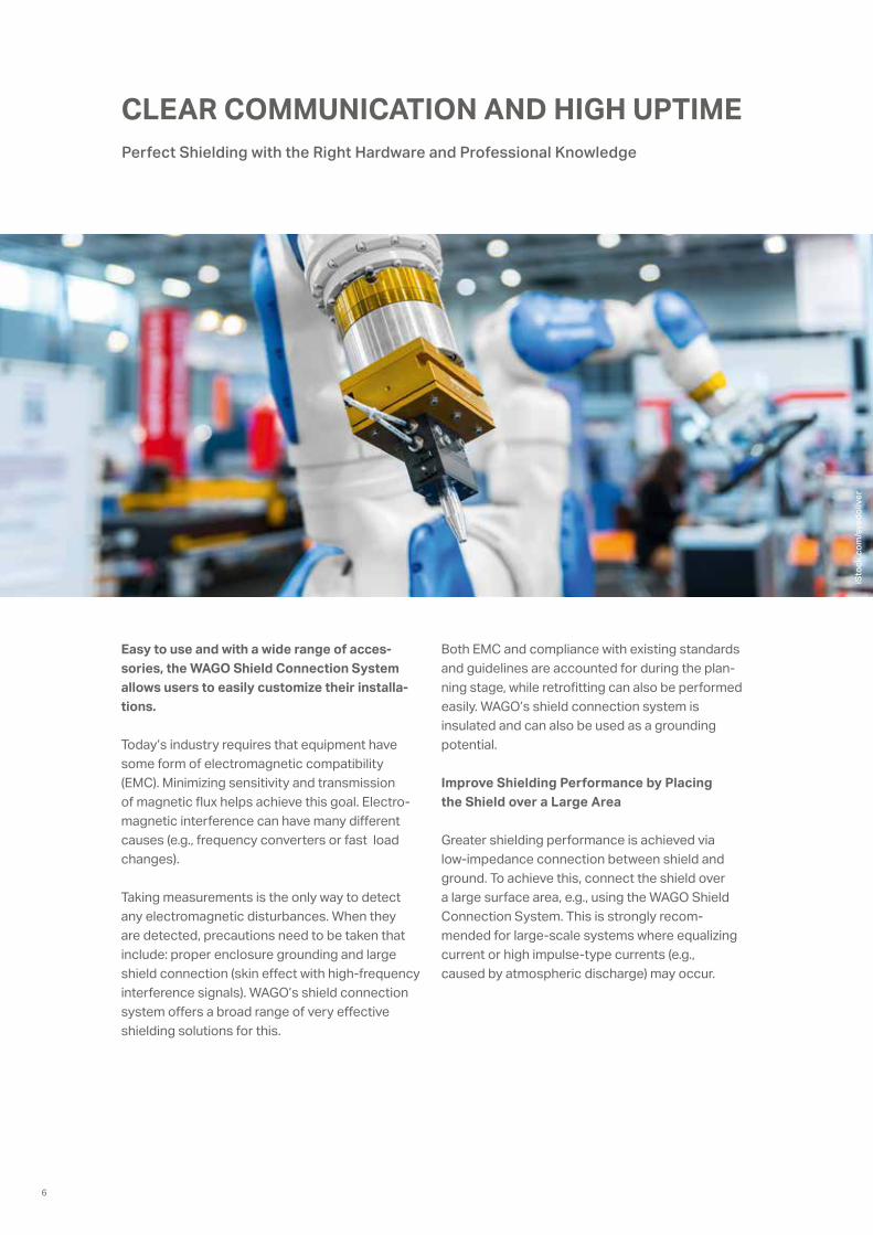
CLEAR COMMUNICATION AND HIGH UPTIME Perfect Shielding with the Right Hardware and Professional Knowledge
Easy to use and with a wide range of acces-sories, the WAGO Shield Connection System allows users to easily customize their installa-tions.
Today’s industry requires that equipment have some form of electromagnetic compatibility (EMC). Minimizing sensitivity and transmission of magnetic flux helps achieve this goal. Electro-magnetic interference can have many different causes (e.g., frequency converters or fast load changes).
Taking measurements is the only way to detect any electromagnetic disturbances. When they are detected, precautions need to be taken that include: proper enclosure grounding and large shield connection (skin effect with high-frequency interference signals). WAGO’s shield connection system offers a broad range of very effective shielding solutions for this.
Both EMC and compliance with existing standards and guidelines are accounted for during the plan- ning stage, while retrofitting can also be performed easily. WAGO’s shield connection system is insulated and can also be used as a grounding potential.
Improve Shielding Performance by Placing the Shield over a Large Area
Greater shielding performance is achieved via low-impedance connection between shield and ground. To achieve this, connect the shield over a large surface area, e.g., using the WAGO Shield Connection System. This is strongly recom-mended for large-scale systems where equalizing current or high impulse-type currents (e.g., caused by atmospheric discharge) may occur.
iSto
ck.c
om/s
vedo
liver
6
100101-100
- 90
- 80
- 70
- 60
- 50
- 40
- 30
- 20
- 10
0
0,10,01
dB
MHz
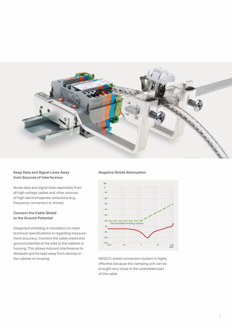
Keep Data and Signal Lines Away from Sources of Interference
Route data and signal lines separately from all high voltage cables and other sources of high electromagnetic emissions (e.g., frequency converters or drives).
Connect the Cable Shield to the Ground Potential
Integrated shielding is mandatory to meet technical specifications in regarding measure- ment accuracy. Connect the cable shield and ground potential at the inlet to the cabinet or housing. This allows induced interference to dissipate and be kept away from devices in the cabinet or housing.
Negative Shield Attenuation
WAGO’s shield connection system is highly effective because the clamping unit can be brought very close to the unshielded part of the cable.
Permissible limiting values
7

®EN 60335-1
geprüft
a pprov ed
NEC Class 2(1)
ADVANCED POWER SUPPLY SYSTEMEPSITRON® – Switched-Mode Power Supplies
The core …
… of the EPSITRON® power supply system consists of power supplies and system modules. This comprehensive portfolio covers nearly all domains of application in the various industries. Its problem-solving expertise can be seen in the unique combination of power supplies and system modules that are industry-proven.
EPSITRON® ECO Power – the Economical Power Supply for Standard Applications
• 1- and 3-phase power supplies, 24 VDC, 30 W … 960 W
• Optional DC OK contact• Available, tool-free CAGE CLAMP®
connection technology• Optional ATEX/IEC Ex approval,
Zone 2 and Class I Div. 2• Versatile mounting options thanks
to DIN-35 rail and screw mountingEPSITRON® CLASSIC Power –
the Robust Power Supply with Optional TopBoost
• 1- and 3-phase power supplies, 12, 24, 48 VDC, 24 W … 960 W
• Error-free, pluggable CAGE CLAMP® connection technology
• DC OK signal/contact• Device marking• Optional integrated TopBoost
EPSITRON® Pro Power – the Professional Power Supply with Optional TopBoost
• TopBoost provides up to 60 A of additional output for 50 ms
• PowerBoost offers up to 200% output power for four seconds
• DC OK contact and stand-by input• LineMonitor (optional) provides configuration
and monitoring of signal inputs and outputs
(1) Observe note on data sheet
8
®
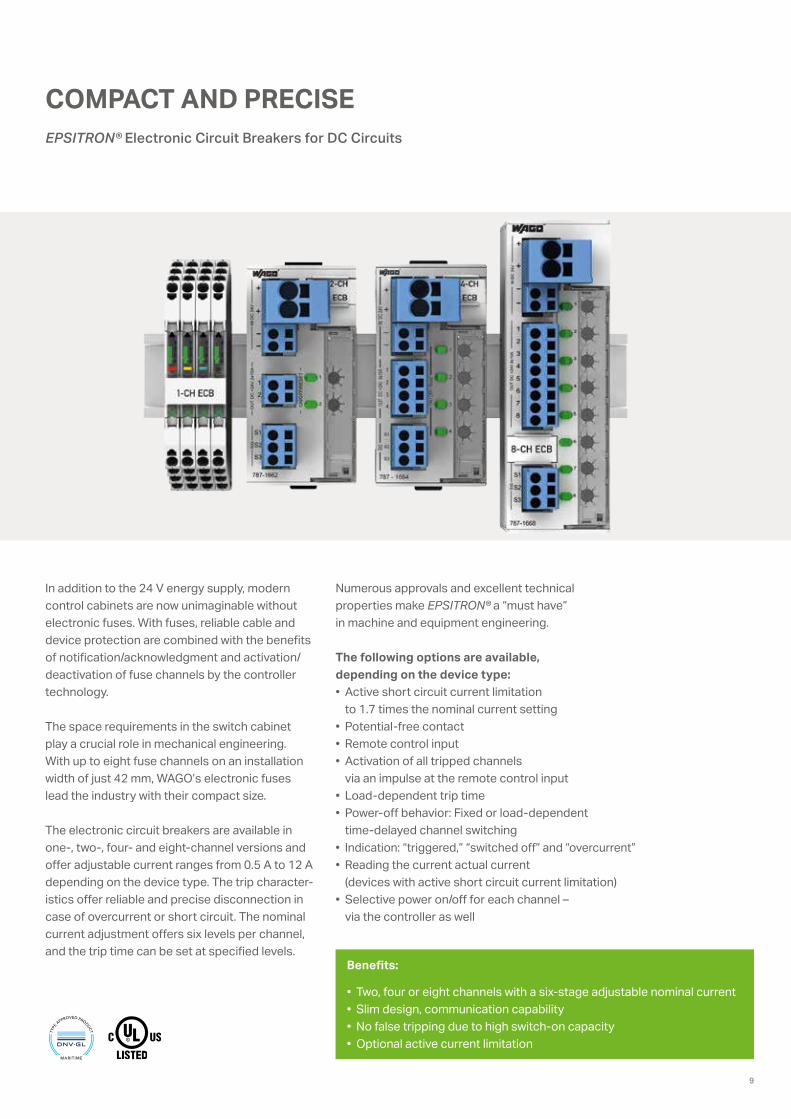
COMPACT AND PRECISEEPSITRON® Electronic Circuit Breakers for DC Circuits
In addition to the 24 V energy supply, modern control cabinets are now unimaginable without electronic fuses. With fuses, reliable cable and device protection are combined with the benefits of notification/acknowledgment and activation/deactivation of fuse channels by the controller technology.
The space requirements in the switch cabinet play a crucial role in mechanical engineering. With up to eight fuse channels on an installation width of just 42 mm, WAGO’s electronic fuses lead the industry with their compact size.
The electronic circuit breakers are available in one-, two-, four- and eight-channel versions and offer adjustable current ranges from 0.5 A to 12 A depending on the device type. The trip character-istics offer reliable and precise disconnection in case of overcurrent or short circuit. The nominal current adjustment offers six levels per channel, and the trip time can be set at specified levels.
Numerous approvals and excellent technical properties make EPSITRON® a “must have” in machine and equipment engineering.
The following options are available, depending on the device type:• Active short circuit current limitation
to 1.7 times the nominal current setting• Potential-free contact• Remote control input• Activation of all tripped channels
via an impulse at the remote control input• Load-dependent trip time• Power-off behavior: Fixed or load-dependent
time-delayed channel switching• Indication: “triggered,” “switched off” and “overcurrent”• Reading the current actual current
(devices with active short circuit current limitation)• Selective power on/off for each channel –
via the controller as well
Benefits:
• Two, four or eight channels with a six-stage adjustable nominal current• Slim design, communication capability• No false tripping due to high switch-on capacity• Optional active current limitation
9
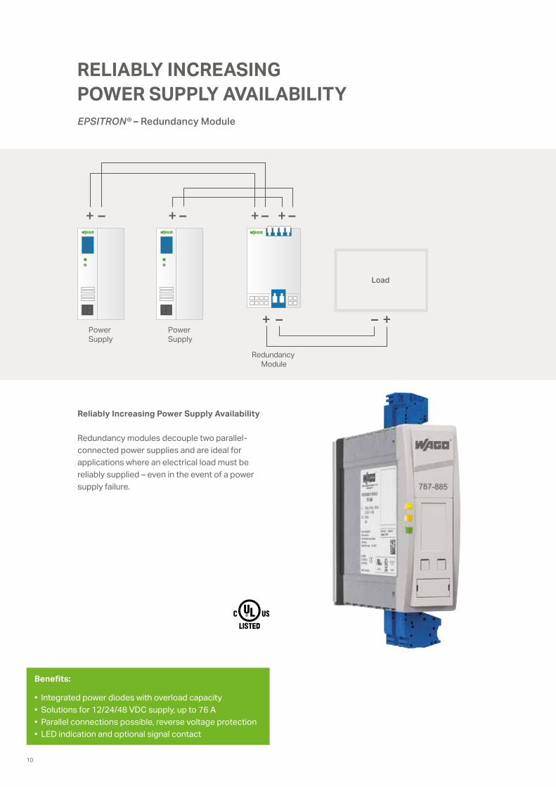
+ – + – + – + –
– ++ –
Load
Power Supply
Power Supply
Redundancy Module
®
RELIABLY INCREASING POWER SUPPLY AVAILABILITYEPSITRON® – Redundancy Module
Reliably Increasing Power Supply Availability
Redundancy modules decouple two parallel- connected power supplies and are ideal for applications where an electrical load must be reliably supplied – even in the event of a power supply failure.
Benefits:
• Integrated power diodes with overload capacity• Solutions for 12/24/48 VDC supply, up to 76 A• Parallel connections possible, reverse voltage protection• LED indication and optional signal contact
10
®
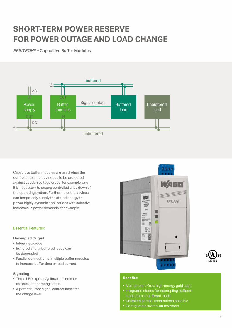
OUT
IN
AC
DC
IN
OUT
Power supply
Buffer modules
Signal contact
buffered
unbuffered
Buffered load
Unbuffered load
SHORT-TERM POWER RESERVE FOR POWER OUTAGE AND LOAD CHANGEEPSITRON® – Capacitive Buffer Modules
Capacitive buffer modules are used when the controller technology needs to be protected against sudden voltage drops, for example, and it is necessary to ensure controlled shut-down of the operating system. Furthermore, the devices can temporarily supply the stored energy to power highly dynamic applications with selective increases in power demands, for example.
Essential Features:
Decoupled Output• Integrated diode• Buffered and unbuffered loads can
be decoupled• Parallel connection of multiple buffer modules
to increase buffer time or load current
Signaling• Three LEDs (green/yellow/red) indicate
the current operating status• A potential-free signal contact indicates
the charge level
Benefits:
• Maintenance-free, high-energy gold caps • Integrated diodes for decoupling buffered
loads from unbuffered loads• Unlimited parallel connections possible• Configurable switch-on threshold
11
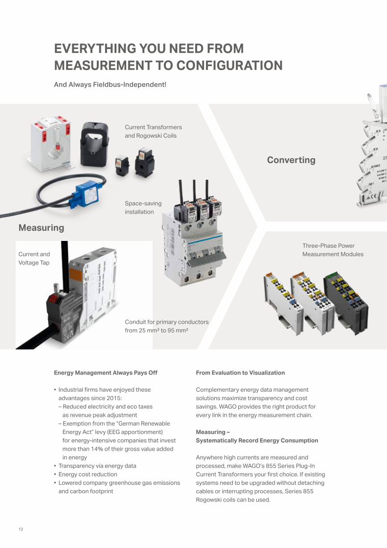
EVERYTHING YOU NEED FROM MEASUREMENT TO CONFIGURATION
From Evaluation to Visualization
Complementary energy data management solutions maximize transparency and cost savings. WAGO provides the right product for every link in the energy measurement chain.
Measuring – Systematically Record Energy Consumption
Anywhere high currents are measured and processed, make WAGO’s 855 Series Plug-In Current Transformers your first choice. If existing systems need to be upgraded without detaching cables or interrupting processes, Series 855 Rogowski coils can be used.
Energy Management Always Pays Off
• Industrial firms have enjoyed these advantages since 2015: – Reduced electricity and eco taxes as revenue peak adjustment – Exemption from the “German Renewable Energy Act” levy (EEG apportionment) for energy-intensive companies that invest more than 14% of their gross value added in energy
• Transparency via energy data• Energy cost reduction• Lowered company greenhouse gas emissions
and carbon footprint
Measuring
Current Transformers and Rogowski Coils
Conduit for primary conductors from 25 mm² to 95 mm²
Current and Voltage Tap
Three-Phase Power Measurement Modules
Space-saving installation
Converting
And Always Fieldbus-Independent!
12
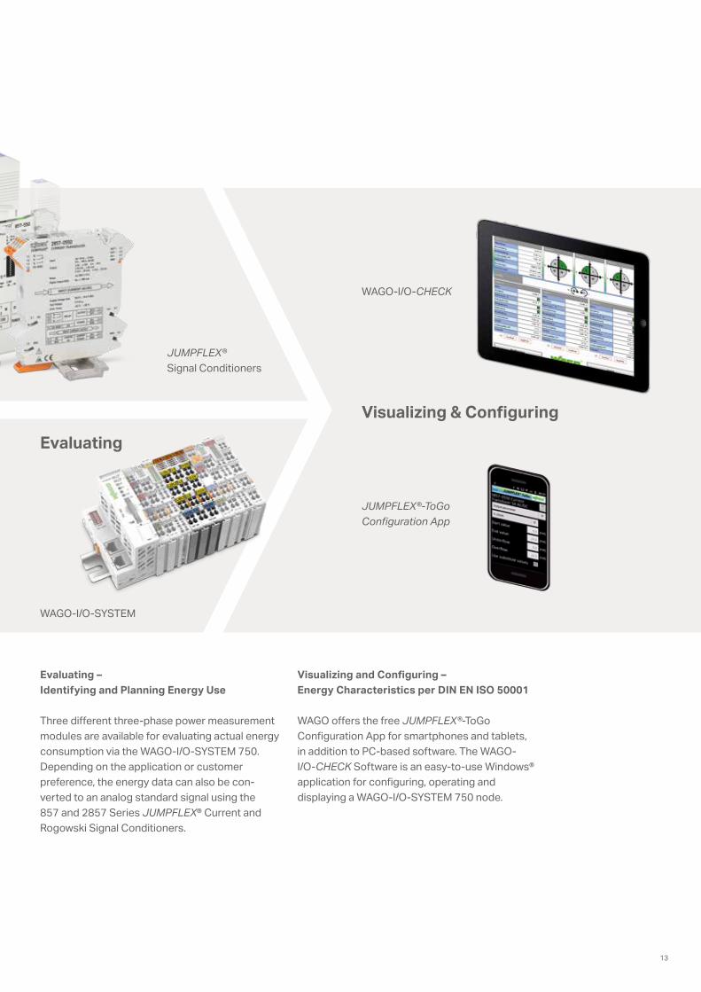
Evaluating – Identifying and Planning Energy Use
Three different three-phase power measurement modules are available for evaluating actual energy consumption via the WAGO-I/O-SYSTEM 750. Depending on the application or customer preference, the energy data can also be con- verted to an analog standard signal using the 857 and 2857 Series JUMPFLEX® Current and Rogowski Signal Conditioners.
Visualizing and Configuring – Energy Characteristics per DIN EN ISO 50001
WAGO offers the free JUMPFLEX®-ToGo Configuration App for smartphones and tablets, in addition to PC-based software. The WAGO- I/O-CHECK Software is an easy-to-use Windows® application for configuring, operating and displaying a WAGO-I/O-SYSTEM 750 node.
JUMPFLEX® Signal Conditioners
Evaluating
JUMPFLEX®-ToGo Configuration App
WAGO-I/O-CHECK
Visualizing & Configuring
WAGO-I/O-SYSTEM
13
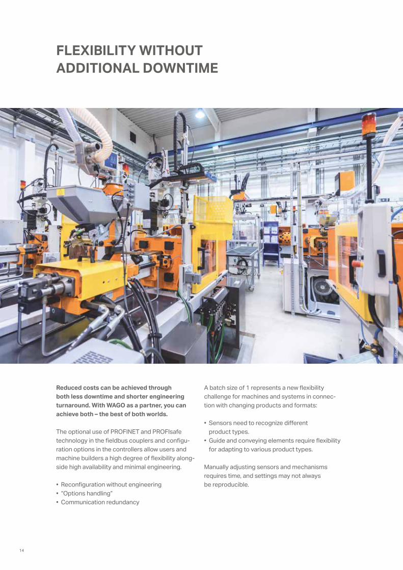
FLEXIBILITY WITHOUT ADDITIONAL DOWNTIME
A batch size of 1 represents a new flexibility challenge for machines and systems in connec-tion with changing products and formats:
• Sensors need to recognize different product types.
• Guide and conveying elements require flexibility for adapting to various product types.
Manually adjusting sensors and mechanisms requires time, and settings may not always be reproducible.
Reduced costs can be achieved through both less downtime and shorter engineering turnaround. With WAGO as a partner, you can achieve both – the best of both worlds.
The optional use of PROFINET and PROFIsafe technology in the fieldbus couplers and configu- ration options in the controllers allow users and machine builders a high degree of flexibility along-side high availability and minimal engineering.
• Reconfiguration without engineering• “Options handling”• Communication redundancy
iSto
ck.c
om/y
oh4n
n
14
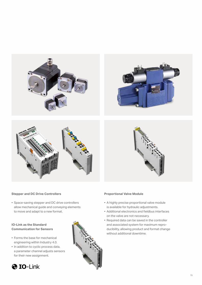
Stepper and DC Drive Controllers
• Space-saving stepper and DC drive controllers allow mechanical guide and conveying elements to move and adapt to a new format.
IO-Link as the Standard Communication for Sensors
• Forms the base for mechanical engineering within Industry 4.0.
• In addition to cyclic process data, a parameter channel adjusts sensors for their new assignment.
Proportional Valve Module
• A highly precise proportional valve module is available for hydraulic adjustments.
• Additional electronics and fieldbus interfaces on the valve are not necessary.
• Required data can be saved in the controller and associated system for maximum repro-ducibility, allowing product and format change without additional downtime.
15
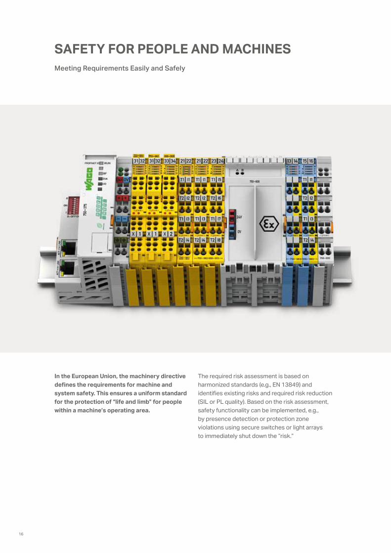
In the European Union, the machinery directive defines the requirements for machine and system safety. This ensures a uniform standard for the protection of “life and limb” for people within a machine’s operating area.
The required risk assessment is based on harmonized standards (e.g., EN 13849) and identifies existing risks and required risk reduction (SIL or PL quality). Based on the risk assessment, safety functionality can be implemented, e.g., by presence detection or protection zone violations using secure switches or light arrays to immediately shut down the “risk.”
SAFETY FOR PEOPLE AND MACHINES Meeting Requirements Easily and Safely
16
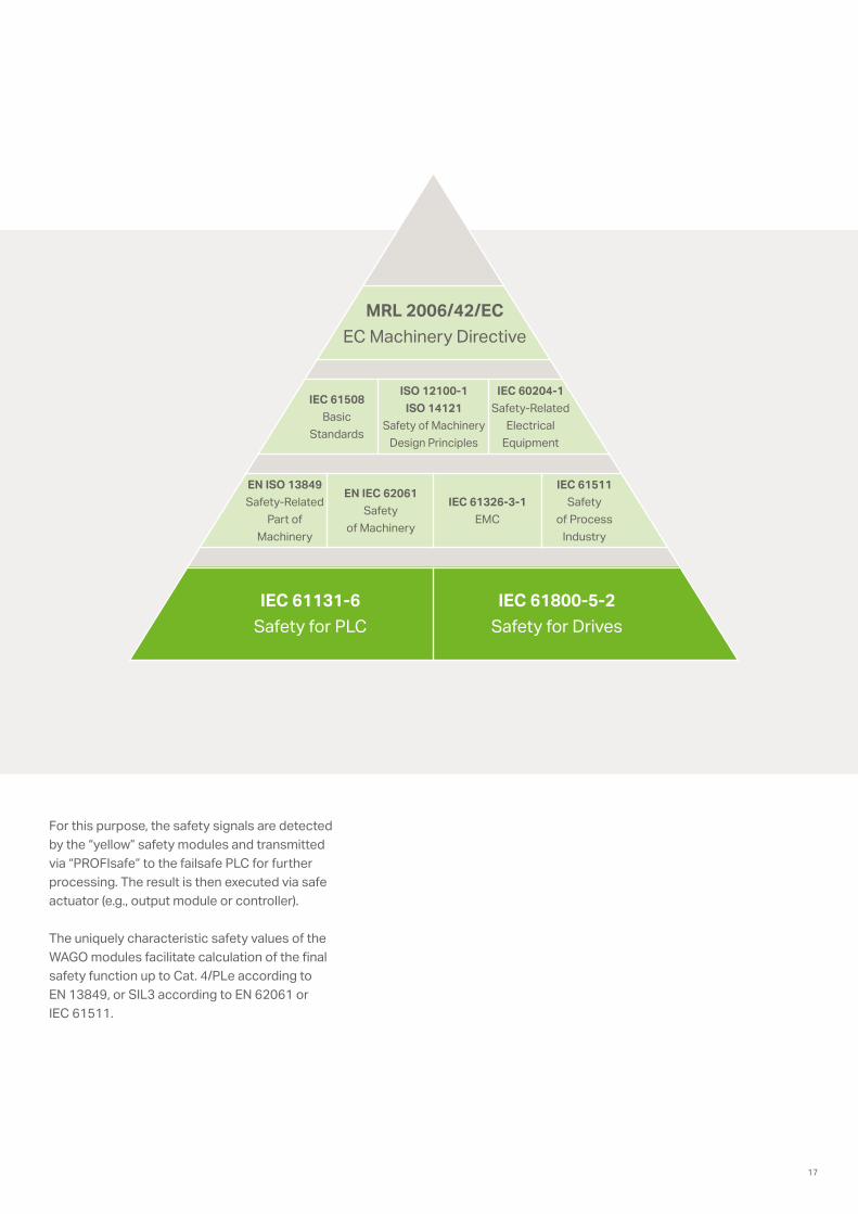
For this purpose, the safety signals are detected by the “yellow” safety modules and transmitted via “PROFIsafe” to the failsafe PLC for further processing. The result is then executed via safe actuator (e.g., output module or controller).
The uniquely characteristic safety values of the WAGO modules facilitate calculation of the final safety function up to Cat. 4/PLe according to EN 13849, or SIL3 according to EN 62061 or IEC 61511.
MRL 2006/42/ECEC Machinery Directive
IEC 61131-6Safety for PLC
EN ISO 13849Safety-Related
Part of Machinery
IEC 61508Basic
Standards
IEC 60204-1Safety-Related
Electrical Equipment
IEC 61511Safety
of Process Industry
EN IEC 62061Safety
of Machinery
IEC 61326-3-1EMC
ISO 12100-1ISO 14121
Safety of Machinery Design Principles
IEC 61800-5-2Safety for Drives
17
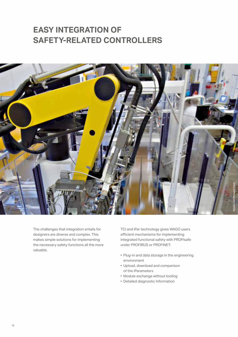
EASY INTEGRATION OF SAFETY-RELATED CONTROLLERS
The challenges that integration entails for designers are diverse and complex. This makes simple solutions for implementing the necessary safety functions all the more valuable.
TCI and iPar technology gives WAGO users efficient mechanisms for implementing integrated functional safety with PROFIsafe under PROFIBUS or PROFINET:
• Plug-in and data storage in the engineering environment
• Upload, download and comparison of the iParameters
• Module exchange without tooling• Detailed diagnostic Information
iSto
ck.c
om/R
icha
rd C
lark
18
1 4
2 5
3 6 4 8
3 7
2 6
1 5
24 V
0 V
24 V
0 V
D01 D02
Safety switching devices/safety module
Bus supply module
Output module
24 V power supply0 V power supply
Safety components
Failsafe output
Failsafe output
Failsafe input
Failsafe input
Logic
Actuator 2
Actuator 1
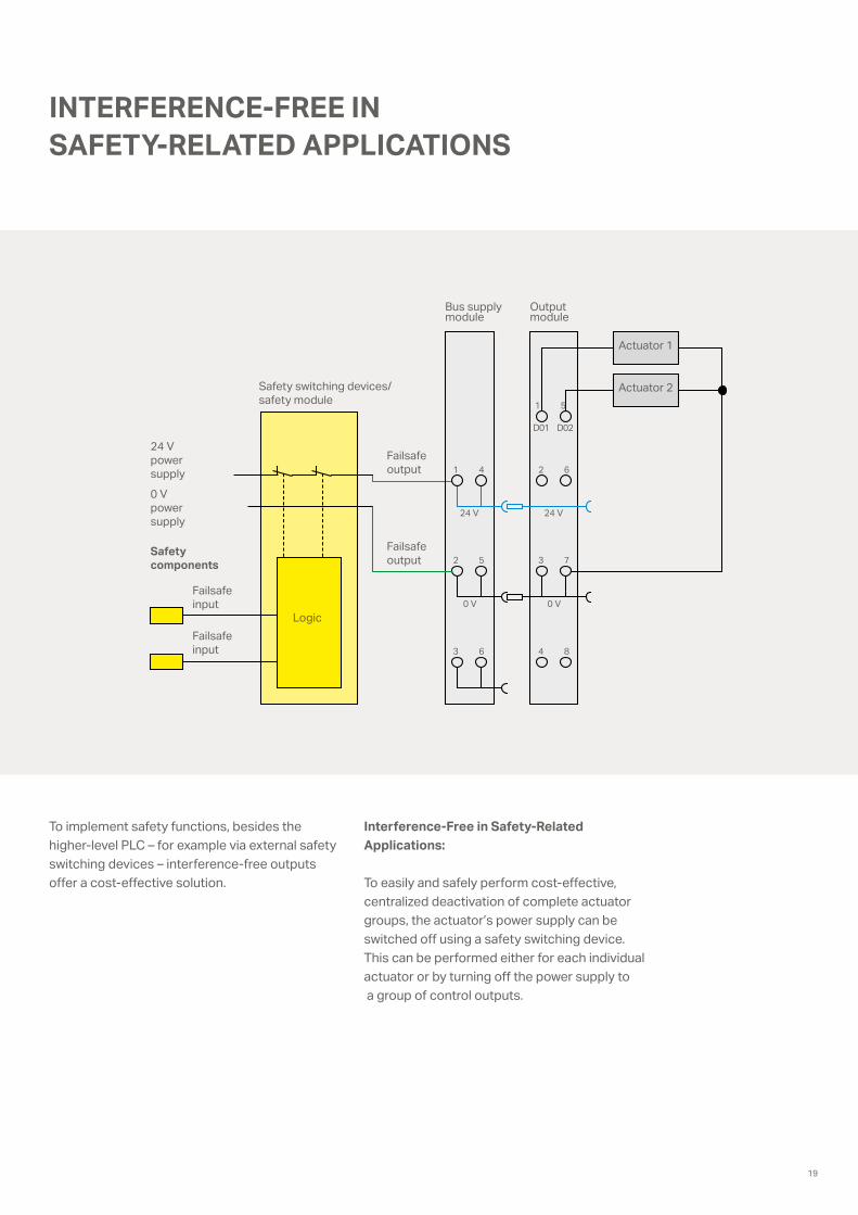
INTERFERENCE-FREE IN SAFETY-RELATED APPLICATIONS
To implement safety functions, besides the higher-level PLC – for example via external safety switching devices – interference-free outputs offer a cost-effective solution.
Interference-Free in Safety-Related Applications:
To easily and safely perform cost-effective, centralized deactivation of complete actuator groups, the actuator’s power supply can be switched off using a safety switching device. This can be performed either for each individual actuator or by turning off the power supply to a group of control outputs.
19
GROUNDING EQUIP 64KA
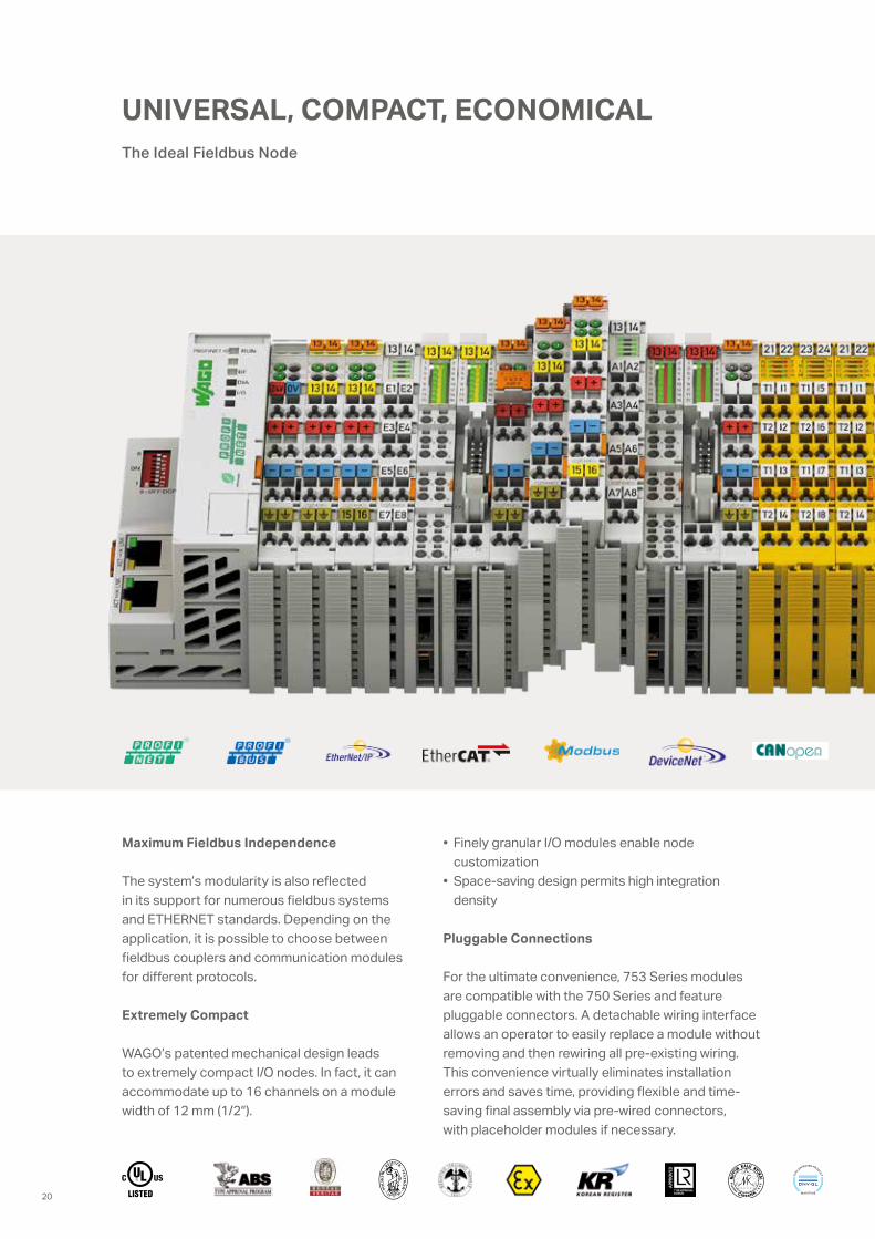
Maximum Fieldbus Independence
The system’s modularity is also reflected in its support for numerous fieldbus systems and ETHERNET standards. Depending on the application, it is possible to choose between fieldbus couplers and communication modules for different protocols.
Extremely Compact
WAGO’s patented mechanical design leads to extremely compact I/O nodes. In fact, it can accommodate up to 16 channels on a module width of 12 mm (1/2″).
• Finely granular I/O modules enable node customization
• Space-saving design permits high integration density
Pluggable Connections
For the ultimate convenience, 753 Series modules are compatible with the 750 Series and feature pluggable connectors. A detachable wiring interface allows an operator to easily replace a module without removing and then rewiring all pre-existing wiring. This convenience virtually eliminates installation errors and saves time, providing flexible and time- saving final assembly via pre-wired connectors, with placeholder modules if necessary.
The Ideal Fieldbus Node
UNIVERSAL, COMPACT, ECONOMICAL
20
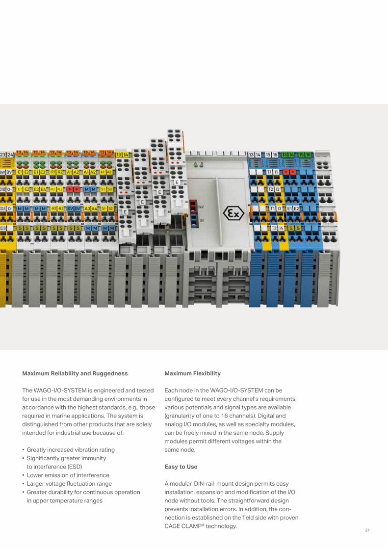
Maximum Reliability and Ruggedness
The WAGO-I/O-SYSTEM is engineered and tested for use in the most demanding environments in accordance with the highest standards, e.g., those required in marine applications. The system is distinguished from other products that are solely intended for industrial use because of:
• Greatly increased vibration rating• Significantly greater immunity
to interference (ESD)• Lower emission of interference• Larger voltage fluctuation range• Greater durability for continuous operation
in upper temperature ranges
Maximum Flexibility
Each node in the WAGO-I/O-SYSTEM can be configured to meet every channel’s requirements; various potentials and signal types are available (granularity of one to 16 channels). Digital and analog I/O modules, as well as specialty modules, can be freely mixed in the same node. Supply modules permit different voltages within the same node.
Easy to Use
A modular, DIN-rail-mount design permits easy installation, expansion and modification of the I/O node without tools. The straightforward design prevents installation errors. In addition, the con-nection is established on the field side with proven CAGE CLAMP® technology.
21
Benefits:
• Simple and economical addition to IP20 automation systems – For stricter requirements on environmental conditions – For plug-and-play connector technology when needed – For simpler cable installation in the form of trunk cables
• High-quality PUR connection cables (drag chains compatible, halogen-free)
• Fully encapsulated (resistance and leak-proofness)• Flange sockets with metal design• Operating temperature range: −25 … +80°C• LEDs for status indication
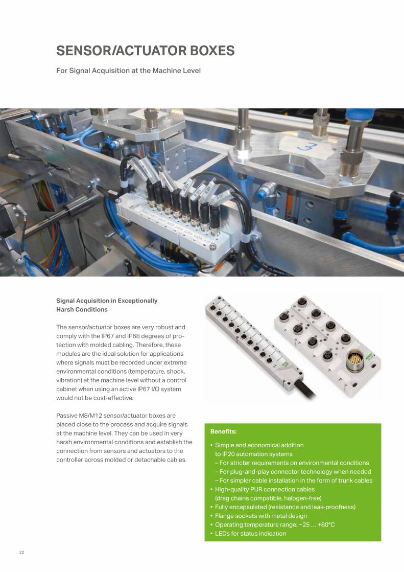
For Signal Acquisition at the Machine Level
SENSOR/ACTUATOR BOXES
Signal Acquisition in Exceptionally Harsh Conditions
The sensor/actuator boxes are very robust and comply with the IP67 and IP68 degrees of pro-tection with molded cabling. Therefore, these modules are the ideal solution for applications where signals must be recorded under extreme environmental conditions (temperature, shock, vibration) at the machine level without a control cabinet when using an active IP67 I/O system would not be cost-effective.
Passive M8/M12 sensor/actuator boxes are placed close to the process and acquire signals at the machine level. They can be used in very harsh environmental conditions and establish the connection from sensors and actuators to the controller across molded or detachable cables.
22
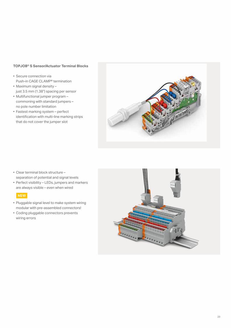
TOPJOB® S Sensor/Actuator Terminal Blocks • Secure connection via
Push-in CAGE CLAMP® termination• Maximum signal density –
just 3.5 mm (1.38”) spacing per sensor• Multifunctional jumper program –
commoning with standard jumpers – no pole number limitation
• Fastest marking system – perfect identification with multi-line marking strips that do not cover the jumper slot
• Clear terminal block structure – separation of potential and signal levels
• Perfect visibility – LEDs, jumpers and markers are always visible – even when wired
• Pluggable signal level to make system wiring modular with pre-assembled connectors!
• Coding pluggable connectors prevents wiring errors
NEW
23
FIELDBUS-INDEPENDENTThe Right Fieldbus Coupler and Controller for Every Application
iSto
ck.c
om/c
hina
face
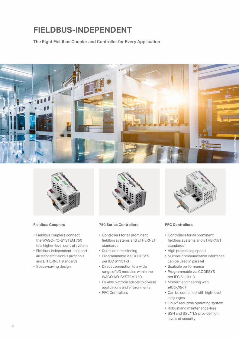
Fieldbus Couplers
• Fieldbus couplers connect the WAGO‐I/O-SYSTEM 750 to a higher-level control system
• Fieldbus-independent – support all standard fieldbus protocols and ETHERNET standards
• Space-saving design
750 Series Controllers
• Controllers for all prominent fieldbus systems and ETHERNET standards
• Quick commissioning • Programmable via CODESYS
per IEC 61131-3• Direct connection to a wide
range of I/O modules within the WAGO-I/O-SYSTEM 750
• Flexible platform adapts to diverse applications and environments
• PFC Controllers
PFC Controllers
• Controllers for all prominent fieldbus systems and ETHERNET standards
• High processing speed• Multiple communication interfaces
can be used in parallel• Scalable performance• Programmable via CODESYS
per IEC 61131-3 • Modern engineering with
e!COCKPIT• Can be combined with high-level
languages• Linux® real-time operating system • Robust and maintenance-free• SSH and SSL/TLS provide high
levels of security
24
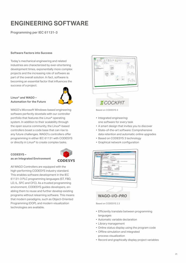
WAGO-I/O-PRO
COCKPIT
Programming per IEC 61131-3
ENGINEERING SOFTWARE
• Integrated engineering: one software for every task
• A smart design that invites you to discover • State-of-the-art software: Comprehensive
data retention and automatic online upgrades • Based on CODESYS 3 technology • Graphical network configuration
Based on CODESYS 3
• Efficiently translate between programming languages
• Automatic variable declaration • Library management• Online status display using the program code • Offline simulation and integrated
process visualization• Record and graphically display project variables
Based on CODESYS 2.3
Software Factors into Success
Today’s mechanical engineering and related industries are characterized by ever-shortening development times, exponentially more complex projects and the increasing role of software as part of the overall solution. In fact, software is becoming an essential factor that influences the success of a project.
Linux® and WAGO – Automation for the Future
WAGO’s Microsoft Windows-based engineering software perfectly dovetails with our controller portfolio that features the Linux® operating system. In addition to their scalability through the open source community, the Linux®-based controllers boast a code base that can rise to any future challenges. WAGO’s controllers offer programming in either IEC 61131 with CODESYS or directly in Linux® to create complex tasks.
CODESYS – as an Integrated Environment
All WAGO Controllers are equipped with the high-performing CODESYS industry standard. This enables software development in the IEC 61131-3 PLC programming languages (ST, FBD, LD, IL, SFC and CFC). As a trusted programming environment, CODESYS guides developers, en-abling them to reuse and further develop existing programs without relearning software. This means that modern paradigms, such as Object-Oriented Programming (OOP), and modern visualization technologies are available.
25
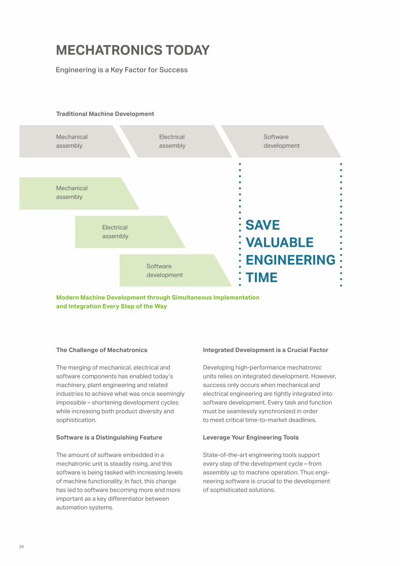
Engineering is a Key Factor for Success
MECHATRONICS TODAY
The Challenge of Mechatronics
The merging of mechanical, electrical and software components has enabled today’s machinery, plant engineering and related industries to achieve what was once seemingly impossible – shortening development cycles while increasing both product diversity and sophistication.
Software is a Distinguishing Feature
The amount of software embedded in a mechatronic unit is steadily rising, and this software is being tasked with increasing levels of machine functionality. In fact, this change has led to software becoming more and more important as a key differentiator between automation systems.
Traditional Machine Development
Modern Machine Development through Simultaneous Implementation and Integration Every Step of the Way
Integrated Development is a Crucial Factor
Developing high-performance mechatronic units relies on integrated development. However, success only occurs when mechanical and electrical engineering are tightly integrated into software development. Every task and function must be seamlessly synchronized in order to meet critical time-to-market deadlines.
Leverage Your Engineering Tools
State-of-the-art engineering tools support every step of the development cycle – from assembly up to machine operation. Thus engi-neering software is crucial to the development of sophisticated solutions.
Software development
Electrical assembly
Mechanical assembly
Software development
Electrical assembly
Mechanical assembly
SAVE VALUABLE ENGINEERING TIME
26
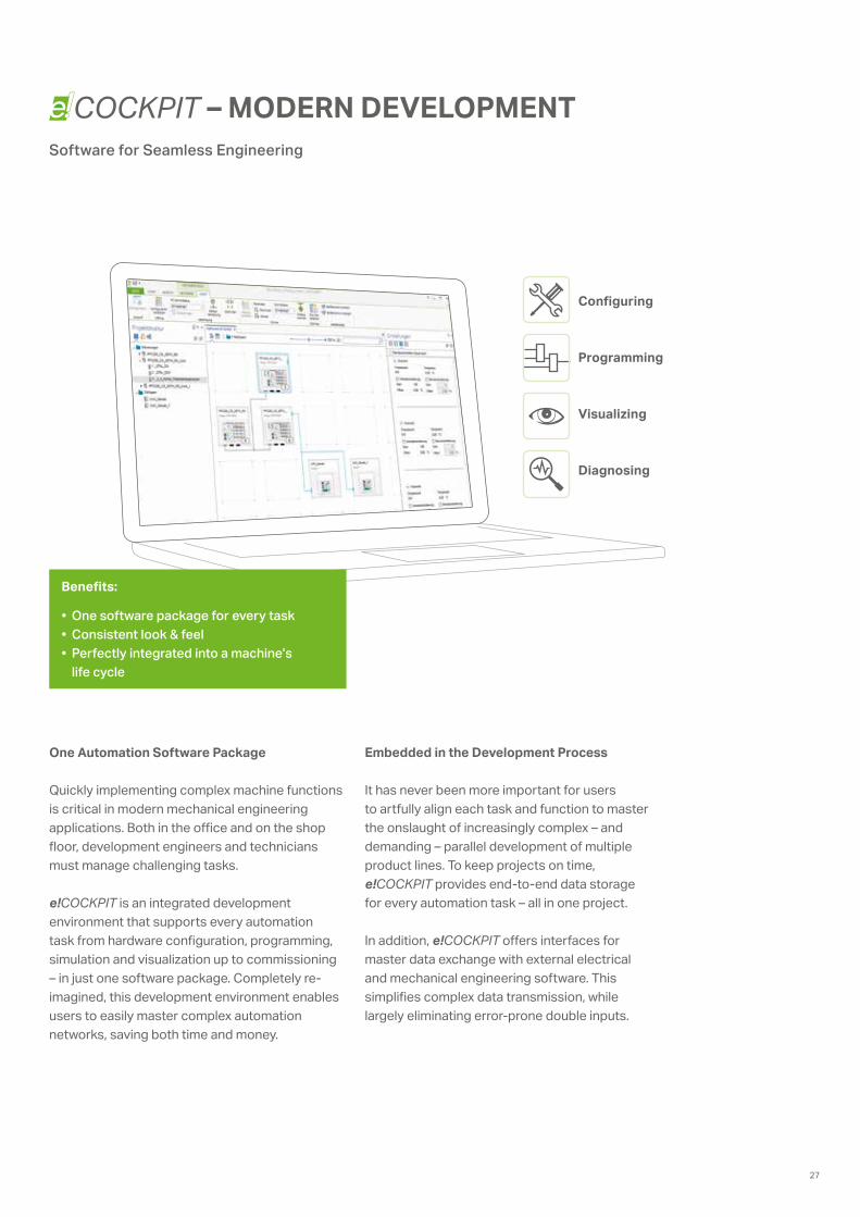
COCKPITSoftware for Seamless Engineering
– MODERN DEVELOPMENT
Benefits:
• One software package for every task• Consistent look & feel• Perfectly integrated into a machine’s
life cycle
One Automation Software Package
Quickly implementing complex machine functions is critical in modern mechanical engineering applications. Both in the office and on the shop floor, development engineers and technicians must manage challenging tasks.
e!COCKPIT is an integrated development environment that supports every automation task from hardware configuration, programming, simulation and visualization up to commissioning – in just one software package. Completely re- imagined, this development environment enables users to easily master complex automation networks, saving both time and money.
Embedded in the Development Process
It has never been more important for users to artfully align each task and function to master the onslaught of increasingly complex – and demanding – parallel development of multiple product lines. To keep projects on time, e!COCKPIT provides end-to-end data storage for every automation task – all in one project.
In addition, e!COCKPIT offers interfaces for master data exchange with external electrical and mechanical engineering software. This simplifies complex data transmission, while largely eliminating error-prone double inputs.
Configuring
Programming
Visualizing
Diagnosing
27

EMBEDDED Linux®Automation for the Future
Uniting what belongs together: High-performance WAGO hardware and future-ready Linux® operating system!
For example, WAGO’s impressive “Embedded Linux®” Controllers have base images that are expandable via open-source packages or by integrating external CODESYS libraries. WAGO is, and will continue to be, a primary source for information on the “open-source” operating system; we are also dedicated to distributing “Board Support Packages” (BSP).
In addition to their scalability through the open-source community, WAGO controllers with open-source operating system boast code bases that are continually developed and maintained by WAGO. This dedication means that the controllers will rise to any future challenges. WAGO’s controllers offer pro- gramming in either IEC 61131 with CODESYS or directly in Linux® to create complex tasks.
Benefits:
• User-friendly• Expandable• Transparency• No need for updates
28
V2 V3
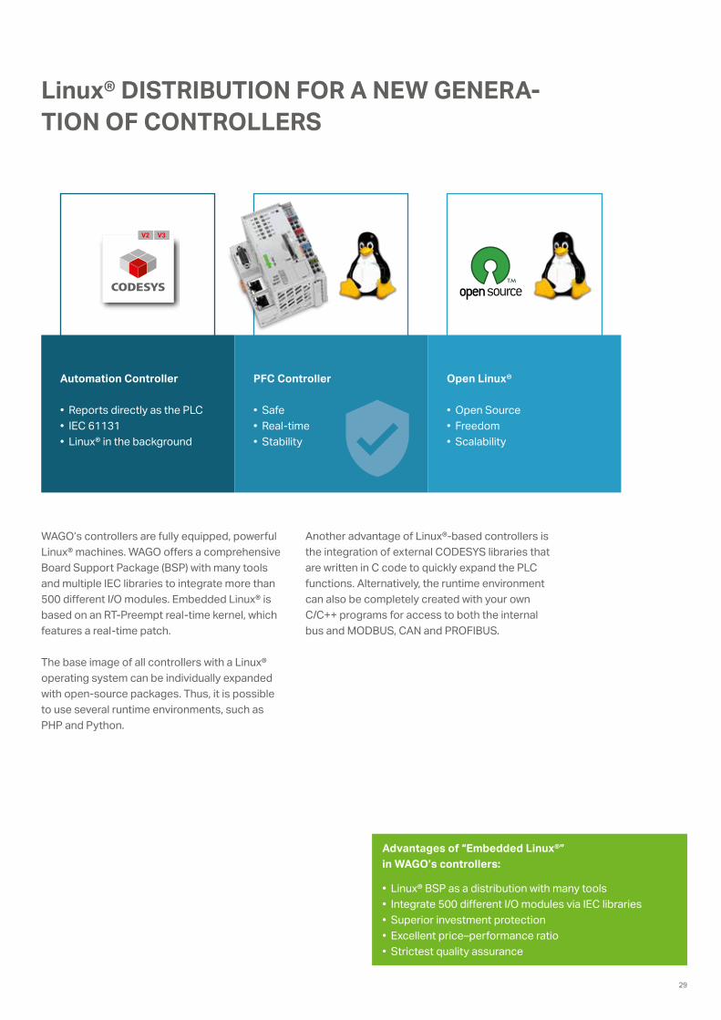
Linux® DISTRIBUTION FOR A NEW GENERA-TION OF CONTROLLERS
WAGO’s controllers are fully equipped, powerful Linux® machines. WAGO offers a comprehensive Board Support Package (BSP) with many tools and multiple IEC libraries to integrate more than 500 different I/O modules. Embedded Linux® is based on an RT-Preempt real-time kernel, which features a real-time patch.
The base image of all controllers with a Linux® operating system can be individually expanded with open-source packages. Thus, it is possible to use several runtime environments, such as PHP and Python.
Another advantage of Linux®-based controllers is the integration of external CODESYS libraries that are written in C code to quickly expand the PLC functions. Alternatively, the runtime environment can also be completely created with your own C/C++ programs for access to both the internal bus and MODBUS, CAN and PROFIBUS.
Advantages of “Embedded Linux®” in WAGO’s controllers:
• Linux® BSP as a distribution with many tools• Integrate 500 different I/O modules via IEC libraries• Superior investment protection • Excellent price–performance ratio• Strictest quality assurance
Automation Controller
• Reports directly as the PLC• IEC 61131• Linux® in the background
Open Linux®
• Open Source• Freedom• Scalability
PFC Controller
• Safe• Real-time• Stability
29
BlattBlatt
Bearb.
10
Urspr
Temperiergerät Linie K
C. Waldmann04.12.2009
+
Datum
MayerDatum
Ersetzt durch
Verteilung 24V DCBehälter-Niveau
ÄnderungGepr
Ersatz von
10029.11.2012 Unilever Deutschland
Produktions GmbH & Co. OHG Werk Heppenheim 12
=
Name 210
\Mixabteilung\Temperiergerät Linie K
0 1 2 3 4 5 6 7 8 9
A1 B
us-A
dapt
.an
alog
Mod
ule
Wagonetzteil230V AC / 24V DC
Bus-
Adap
t.di
gita
le M
odul
eN
ivea
u-Sc
halte
r
A2 T
ouch
PC
Dur
chflu
ss-
mes
ser
Behälter-Niveau
Niveau-Schalter
Nac
hfül
len
Voll
Rese
rve
T1
+
1
2
F01
1
2F14A
L1
+
N
1
2
F02
-
PE
-
1
2
F03
1
2
F04L- L- L- L- L- L- L- L- L-
E1A1
A2 E1
7X2
1
E2
2
E3
8
11
12 14
1
2F22A
L1/10.8
L2/10.8
L3/10.8
N/10.8
PE/10.8
F01L
+/
100.
0
F02L
+/
100.
0
F03L
+/
F04L
+/
200.
0
F01L
-/
100.
0
F02L
-/
100.
0
F03L
-/
F04L
-/
DI4
/20
7.8
DI3
/20
7.6
L1 /
L2 /
L3 /
N /
PE /
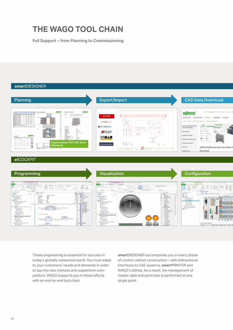
Output options: PDF, CSV, Excel (clipboard)
smartDESIGNER
e!COCKPIT
Planning Export/Import CAD Data Download
Programming Visualization Configuration
Timely engineering is essential for success in today’s globally networked world. You must adapt to your customers’ needs and demands in order to tap into new markets and outperform com- petitors. WAGO supports you in these efforts with an end-to-end tool chain.
smartDESIGNER accompanies you in every phase of control cabinet construction – with bidirectional interfaces to CAE systems, smartPRINTER and WAGO’s eShop. As a result, the management of master data and parts lists is performed at one single point.
THE WAGO TOOL CHAIN Full Support – from Planning to Commissioning
30

Marking
Diagnostics
Continual Support:
• e!COCKPIT for integrated engineering in automation• smartDESIGNER for the life cycle of a control cabinet• Seamless integration into CAE systems
e!COCKPIT invites you to discover: All project visualization from graphic network design up to the parameterization and diagnostics of the WAGO-I/O-SYSTEM 750, standards- compliant programming in CODESYS 3.5, modern visualization in HTML5.
31
INDUSTRY 4.0
Measure First, Then Manage
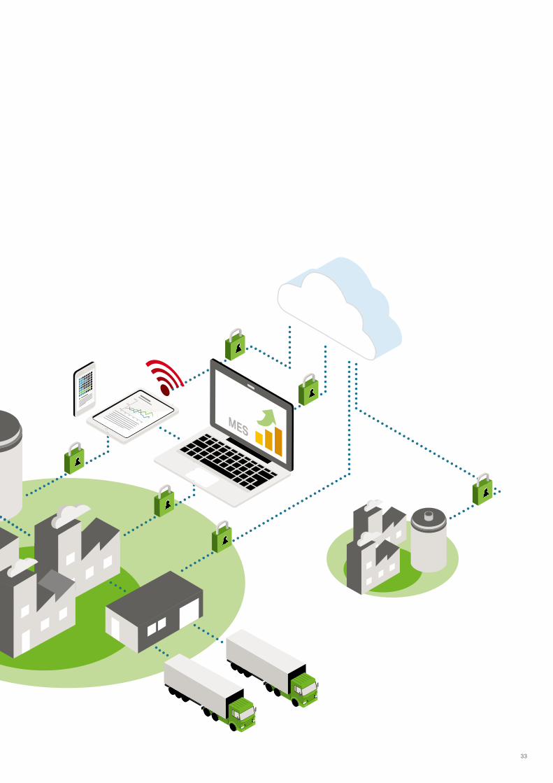
The “smart factory” is an important milestone in the process of evolution to Industry 4.0. The production line of the future will not only be networked and intelligent – it will control and optimize itself, partially automatically too, making it resource-efficient.
From the central perspectives of developing the range of Industry 4.0 topics, the various technologies will play a pragmatic role. Invest-ments in network infrastructure, data security and data transparency – ultimately investments in horizontal and vertical integration – primarily serve the purpose of cost-effective production. Against the background of global competition and the demand for product customization, right down to a batch size of 1, this objective is vitally important.
Resource efficiency and the optimization of systems engineering, for example, offer starting points for the improvement of the production processes. Necessary preconditions for the trans-formation of an existing factory into an “intelligent factory” include networking existing processes and recording all relevant product, machine and process data. The evaluation on the basis of relational algorithms then supplies the necessary information (KPIs) for directing the production process and indications of latent optimization potential.
Automation solutions such as the WAGO-I/O- SYSTEM 750 are already available now for recording, capturing and transferring data into a “Manufacturing Execution System” (MES) or product management system. With over 500 modules and the powerful PFC200 Controllers, it offers an appropriate solution for nearly any domain of application. This also applies especially to integration into existing systems.
To maximize resource efficiency during produc-tion, you need transparent information on produc-tion procedures, performance and quality. And the way to achieve this is by ensuring all components are networked and “speaking” to each other during the value creation process. This process works best with modular automation technology.
The First Milestone – the Smart Factory
32
0%
50%
100%
0102
0304
0506
33
INDUSTRY 4.0
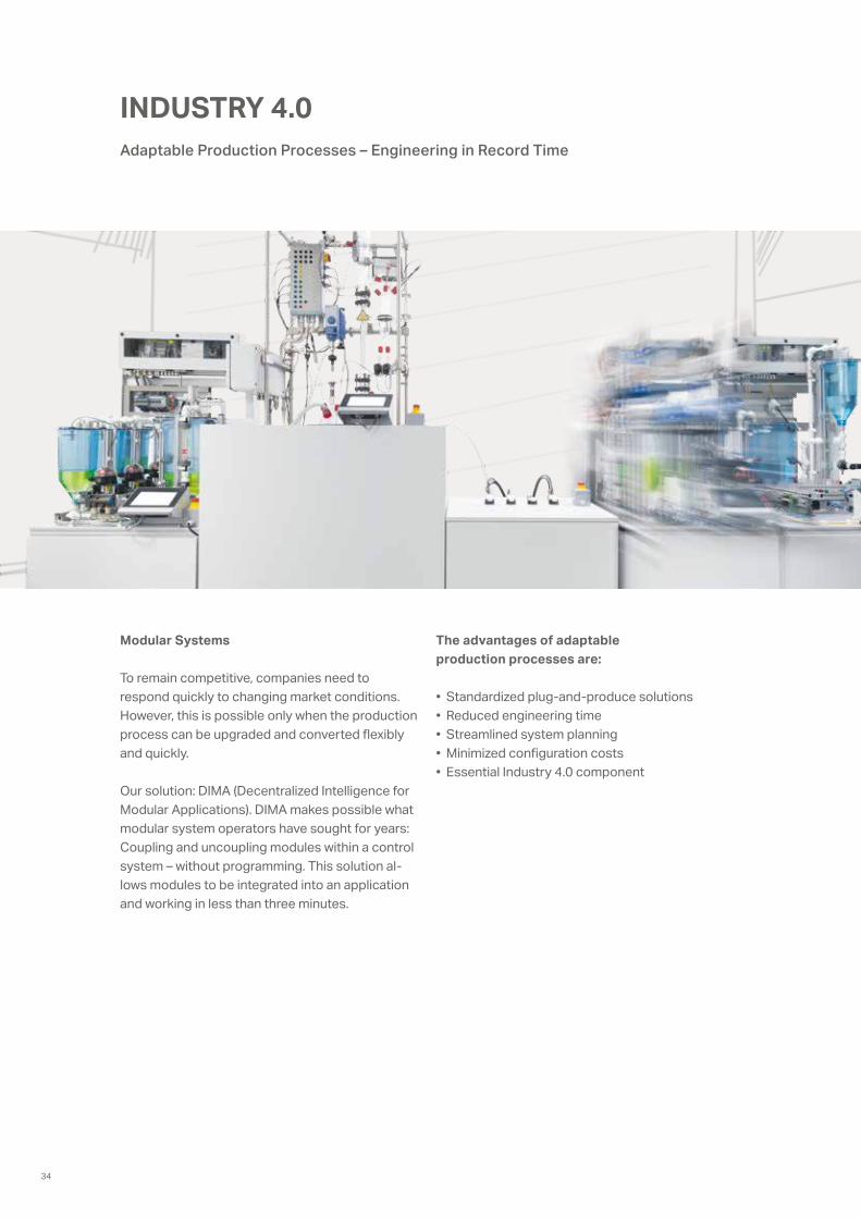
Modular Systems
To remain competitive, companies need to respond quickly to changing market conditions. However, this is possible only when the production process can be upgraded and converted flexibly and quickly.
Our solution: DIMA (Decentralized Intelligence for Modular Applications). DIMA makes possible what modular system operators have sought for years: Coupling and uncoupling modules within a control system – without programming. This solution al-lows modules to be integrated into an application and working in less than three minutes.
The advantages of adaptable production processes are:
• Standardized plug-and-produce solutions• Reduced engineering time• Streamlined system planning• Minimized configuration costs • Essential Industry 4.0 component
Adaptable Production Processes – Engineering in Record Time
34
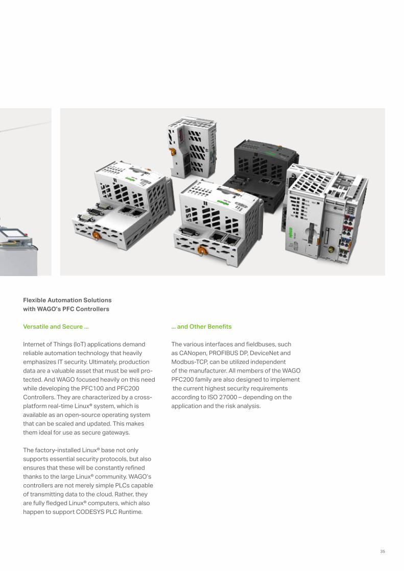
Flexible Automation Solutions with WAGO’s PFC Controllers
Versatile and Secure ...
Internet of Things (IoT) applications demand reliable automation technology that heavily emphasizes IT security. Ultimately, production data are a valuable asset that must be well pro-tected. And WAGO focused heavily on this need while developing the PFC100 and PFC200 Controllers. They are characterized by a cross- platform real-time Linux® system, which is available as an open-source operating system that can be scaled and updated. This makes them ideal for use as secure gateways.
The factory-installed Linux® base not only supports essential security protocols, but also ensures that these will be constantly refined thanks to the large Linux® community. WAGO’s controllers are not merely simple PLCs capable of transmitting data to the cloud. Rather, they are fully fledged Linux® computers, which also happen to support CODESYS PLC Runtime.
... and Other Benefits
The various interfaces and fieldbuses, such as CANopen, PROFIBUS DP, DeviceNet and Modbus-TCP, can be utilized independent of the manufacturer. All members of the WAGO PFC200 family are also designed to implement the current highest security requirements according to ISO 27000 – depending on the application and the risk analysis.
35
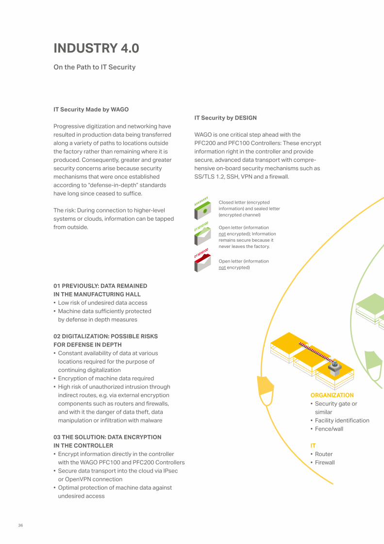
INDUSTRY 4.0
IT Security Made by WAGO
Progressive digitization and networking have resulted in production data being transferred along a variety of paths to locations outside the factory rather than remaining where it is produced. Consequently, greater and greater security concerns arise because security mechanisms that were once established according to “defense-in-depth” standards have long since ceased to suffice.
The risk: During connection to higher-level systems or clouds, information can be tapped from outside.
IT Security by DESIGN
WAGO is one critical step ahead with the PFC200 and PFC100 Controllers: These encrypt information right in the controller and provide secure, advanced data transport with compre- hensive on-board security mechanisms such as SS/TLS 1.2, SSH, VPN and a firewall.
01 PREVIOUSLY: DATA REMAINED IN THE MANUFACTURING HALL• Low risk of undesired data access• Machine data sufficiently protected
by defense in depth measures
02 DIGITALIZATION: POSSIBLE RISKS FOR DEFENSE IN DEPTH• Constant availability of data at various
locations required for the purpose of continuing digitalization
• Encryption of machine data required• High risk of unauthorized intrusion through
indirect routes, e.g. via external encryption components such as routers and firewalls, and with it the danger of data theft, data manipulation or infiltration with malware
03 THE SOLUTION: DATA ENCRYPTION IN THE CONTROLLER• Encrypt information directly in the controller
with the WAGO PFC100 and PFC200 Controllers• Secure data transport into the cloud via IPsec
or OpenVPN connection• Optimal protection of machine data against
undesired access
On the Path to IT Security
Closed letter (encrypted information) and sealed letter (encrypted channel)
Open letter (information not encrypted); Information remains secure because it never leaves the factory.
Open letter (information not encrypted)
ORGANIZATION• Security gate or
similar• Facility identification• Fence/wall
IT• Router• Firewall
36
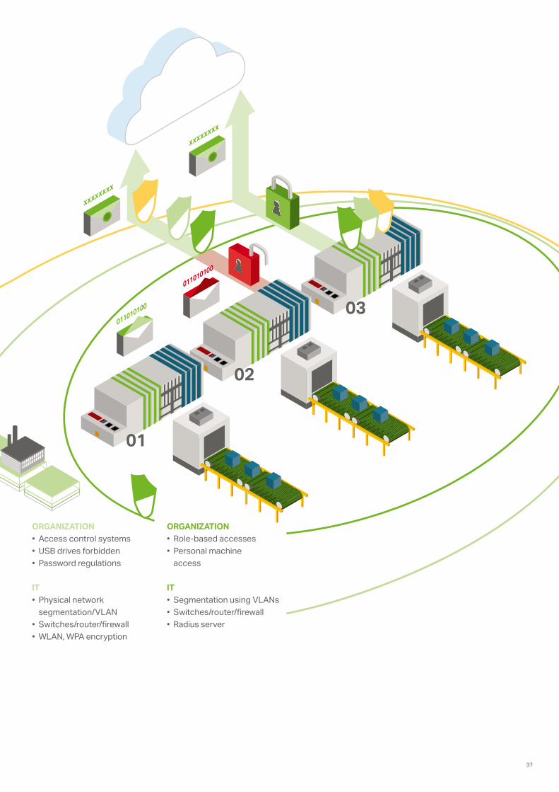
ORGANIZATION• Access control systems• USB drives forbidden• Password regulations
IT• Physical network
segmentation/VLAN• Switches/router/firewall• WLAN, WPA encryption
ORGANIZATION• Role-based accesses• Personal machine
access
IT• Segmentation using VLANs• Switches/router/firewall• Radius server
37
1
Rail-Mounted Terminal Block Systems
Full Line Catalog, Volume 1 – Edition 2015/2016
Rail-
Mou
nted
Ter
min
al B
lock
Sys
tem
s
Full L
ine
Cata
log
2015
/201
6
3
Automation Technology
Full Line Catalog, Volume 3 – Edition 2015/2016
Auto
mat
ion
Tech
nolo
gy
Full L
ine
Cata
log
2015
/201
6
4
Interface Electronic
Full Line Catalog, Volume 4 – Edition 2015/2016
Inte
rfac
e El
ectr
onic
Full L
ine
Cata
log
2015
/201
6
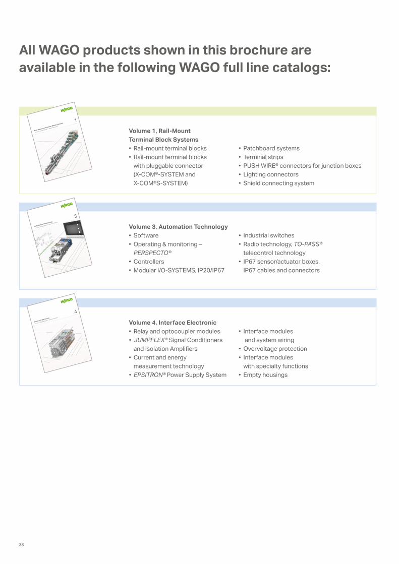
All WAGO products shown in this brochure are available in the following WAGO full line catalogs:
Volume 1, Rail-Mount Terminal Block Systems• Rail-mount terminal blocks• Rail-mount terminal blocks
with pluggable connector (X-COM®-SYSTEM and X-COM®S-SYSTEM)
Volume 3, Automation Technology• Software• Operating & monitoring –
PERSPECTO®• Controllers• Modular I/O-SYSTEMS, IP20/IP67
Volume 4, Interface Electronic• Relay and optocoupler modules• JUMPFLEX® Signal Conditioners
and Isolation Amplifiers• Current and energy
measurement technology• EPSITRON® Power Supply System
• Patchboard systems• Terminal strips• PUSH WIRE® connectors for junction boxes• Lighting connectors• Shield connecting system
• Industrial switches• Radio technology, TO-PASS®
telecontrol technology• IP67 sensor/actuator boxes,
IP67 cables and connectors
• Interface modules and system wiring
• Overvoltage protection• Interface modules
with specialty functions• Empty housings
38

39
6033
7813
– 0
888-
0123
/010
0-69
01 –
FAC
TORY
BRO
CH
URE
1.0
US –
05/
2017
– P
rinte
d in
Ger
man
y –
Subj
ect t
o de
sign
cha
nges
. Titl
e th
eme:
iSto
ck.c
om/c
hina
face
WAGO is a registered trademark of WAGO Verwaltungsgesellschaft mbH.“Copyright – WAGO Kontakttechnik GmbH & Co. KG – all rights reserved. The content and structure of the WAGO websites, catalogs, videos, and other WAGO media are subject tocopyright. Distribution or modification to the contents of these pages and videos is prohibited. Furthermore, the content may neither be copied nor made available to third parties forcommercial purposes. Also subject to copyright are the images and videos that were made available to WAGO Kontakttechnik GmbH & Co. KG by third parties.”
WAGO Kontakttechnik GmbH & Co. KGPostfach 2880 · 32385 MindenHansastraße 27 · 32423 [email protected]
Headquarters +49 571/ 887 - 0Sales +49 571/ 887 - 222Order Service +49 571/ 887 - 44 333Fax +49 571/ 887 - 844 169