Embed Size (px)
Citation preview

Pure &App/ . Chem., Vol. 60, No. 5, pp. 619-632, 1988. Printed in Great Britain. @ 1988 IUPAC
Industrial-worthy plasma torches: State-of-the-art
S. L. Camacho
Plasma Energy Corporation, Umstead Industrial Park, Raleigh, NORTH CAROLINA 27612 USA
ABSTRACT: Plasma arc torches are being applied today as unique heating tools in industrial processes. The many benefits of using plasma torches are being demonstrated in different production plants and prototype equipment around the world. And the successful demonstration of this versatile, low-mass, controlled high-enthalpy, selective-atmosphere, heat source is generating new applications. Industry today is benefiting from plasma heating and will in the future derive more benefits from this proven heating technology.
There are many different types of plasma arc torches available. Single torch power ratings range from 20 kilowatts to 60 megawatts. The plasma heaters at the low and high ends of the power range are employed in the universities and in the national research laboratories for basic scientific studies. The industrial sector, with its emphasis on longevity and economy, has adapted only the plasma heaters in the range from 20 k~ to 8 mW.
The operating life of plasma systems is very important in industry for economic reasons. Industrial processes that use plasma torches must be capable of many hours or weeks of continuous or cumulative operating life, unlike the several minutes of operating life demanded of the 60-mW plasma heater that is used for re-entry heating simulation at NASA's Ames Research Center in California.
This lecture will present the state-of-the-art of plasma torches and discuss their physical designs and operating characteristics. Because of time constraints the lecture will place emphasis on devices, with all the limitations that the terms imply.
INTRODUCTION
The presence of plasma torches in the industrial sector is becoming more evident, There has been a very significant growth in the employment of high-power plasma torches during the last three years; while the growth of low-power plasma torches for cutting, welding, material deposition, etc., had been steady since their introduction in the late 1950s.
The high-power plasma torches applied to industrial processes may be traced to Schoenherr's work in Germany and Birkeland's work in Norway during the early years of this century. 1,2 Birkeland's torch for nitrogen fixation has since been abandoned, but the torch for acetylene production in Germany continued even until today. These torches had hollow
A t mid-century, industry in the US and around the world started to apply the W m c t r o k torch of Gage. 3 And the wide industrial application of induction plasma torches followed soon thereafter. 4 These three generic types of plasma torches remain the most popular and the most widely adapted in industry.
electrodes.
619

620 S. L. CAMACHO
The NASA Space Program redirected the aim of plasma torch development during the decade of the 1960s from industrial applications & specialized studies in re-entry heat simulation and heat shield ablation. After the successful landing of US astronauts on the moon, the development of plasma torches was redirected to the industrial applications. And NASA is credited with significant achievements in the development of the
Today in the decade of the 1980s plasma technology is enjoying a remarkable growth as a unique heating tool for industrial processes. During just the last three years high-power plasma torches of one-megawatt and larger were applied industrially in steelmaking, refractory metal recycling, powder metallurgy, ceramics, iron smelting, and other industrial processes. There is optimism in the air.
I want to share with you an observation and draw a parallel between today's optimistic outlook for plasma and the outlook for plasma 25 years ago.
I have followed the development of plasma heaters starting in 1961 as an electrical engineer in a NASA research laboratory. Our task then was very narrowly directed: to design and build a heater that can raise the internal energy or enthalpy of a gas. The pace was very hectic in those early years because the need was immediate. Consider, for a moment, the environment that existed in the early 1960s.
The designers of the space vehicles needed characteristics data on the aspect ratios of.the protective heat shields for the Mercury, Gemini and Apollo spacecrafts. The developers of the heat shield needed to test their material formulations and production techniques. And the astronauts wanted verification that the heat shield materials will survive the re-entry heats.
I sense today the glimpse of another resurgent of interest in plasma arc heating, but minus the national commitment of resources. Plasma technology will have to make it on its own merit in the industrial sector or forever remain only a tool for nationally-funded programs. If we maintain the present pace of developing industrial applications, of plasma, I am more inclined to believe that plasma technology will make it on its own technical and economic merits.
technology and art of plasma heating.
THE PLASMA PHENOMENA
A familiarity with plasma phenomena is essential to understanding the bases for the design and operation of plasma torches, So let us briefly review some plasma phenomena.
We all have encountered situations that provide ample evidence of the phenomena of the plasma state, the fourth state of matter. As examples, we all have observed the electrical discharges during lightning storms. Some of us have observed an electrical discharge when we switched off a home appliance or when we accidentally "shorted" the wires of our car battery. And some of us have been fortunate enough to observe the Aurora Borealis in the Arctic Region of the Northern Hemisphere or the Aurora Australis in the Anarctic Region of the Southern Hemisphere. These are all visual observations of the phenomena of the plasma state.
Soon after a lightning storm, the sky may be cleared as if by some magic. Perhaps magic cannot explain everything. Another explanation is: the upward motions of air masses that were initiated by the heat of the lightning bolt plasma discharge "cleared" the air.
After we observed the spark on the switch of the appliance, we sensed that the switch was warm. The source of heat was the plasma arc discharge that was initiated when the contacts of the switch opened.
And the beautiful colors and patterns of the Aurora Borealis and the Aurora Australis we now attribute to the flow of plasma particles called the coming from the sun and their interactions with the magnetic fields of the earth.
So what is w? Plasma is a gas wherein electrons, ions, and neutral gas species co-exist. The mixture of charged and neutral gas species is
Industrial-worth y plasma torches 621
unique and responds to electromagnetic forces. A source of voltage or a magnet can each influence the plasma. Free electric charges co-exist in a plasma, and the negative and positive charges compensate each other to give the plasma its property of quasi-neutrality.
Here is another definition of m. Plasma is any ordinary gas that has been conditioned to respond to electric fields and magnetic fields. [You may select your choice of definition to suit your purposes.]
But what are electric ' fields and mgmLu ' fields? And how are they formed?
In simple terms, an electric field and a magnetic field are invisible forces that influence the motion of electrons and ions; more so the motion of electrons than the motion of ions because electrons are lighter. The exhibited behavior of the plasma in response to electric and magnetic forces is often referred to as the electromagnetic characteristics of plasma.
An electric field is formed whenever a voltage is established between two points. For example, an electric field is formed between the two poles of a car battery. And a magnetic field is formed around a wire whenever an electric current is flowing through the wire. The electric field and magnetic field may be constant or changing, depending on whether the source of voltage or the source of current, respectively, is constant or changing.
How then can a gas be conditioned into a and made to respond to electric and magnetic fields? The work of gas conditioning is the function of the plasma torch.
THE PLASMA TORCH
The plasma torch generates and maintains a gaseous electrical conducting element-----and uses the resistance of the &?lasna to convert electricity into heat energy. The electricity-to-heat conversion is similar to the heating process in an electric bread toaster, with one important difference. The metal heating element in the toaster melts and breaks at the melting temperature of the metal; the plasma heating element will not break at high temperature. So we can achieve higher temperatures with plasma heaters.
Using a small flowrate of any gas, the plasma torch initiates an arc discharge in the gas between the electrodes and creates the plasma state within only a tiny portion of the gas. Less than a half of a percent of the total gas flowrate participates in the arc discharge and reaches the plasma state. 5 But this tiny level of ionization is sufficient to create and maintain the plasma heating element. The remainder of the gas flowrate is heated by the plasma via all three mechanisms of heat transfer. The plasma state is maintained between the electrodes of the plasma torch by electrical and mechanical stabilization that are built into the plasma torch hardware.
Two arc attachment points are required to generate a plasma column: one attachment point at the - interface at the cathode electrode and another at the aae-solid interface at the anode electrode. The two electrodes are separated by an insulator, to preserve the potential difference that exists between them. The two points of arc attachments are controlled by complex phenomena that are not yet fully understood.6
Very high temperatures are encountered at the attachment points of the plasma that exceed the melting temperature of any electrode material now known. Therefore, the vaporization of electrode materials at the attachment points is accepted and water cooling is used to minimize the rate of vaporization of electrode materials.
THREE GENERIC PLASMA TORCH DESIGNS: Figure No. 1 shows three generic designs of plasma torches and the components of each plasma torch design. The basic components of the hollow electrode HE and solid electrode SE plasma torch include: cathode electrode, anode electrode, insulator, gas for stabilizing the plasma column (part of the gas is ionized to create the plasma column), The components of the electrodeless rn plasma torch include: multi-turn magnetic coil, quartz tube gas enclosure, quartz tube holder, gas injector, and water for cooling the coil.
and water for cooling the component parts.

622 S. L. CAMACHO
GAS Q
(ANODE OR CATHODE) (ANODE .-I; OR ELECTRODE CATHODE)
G I I I I PLASMA
T NT .. . HE SE SP RP . .. AC SM
L E G TRANSFERRED MODE NON-TRANSFERRED MO E
SOLID ELECTROM(S) STRAIGHT POLARITY REVERSE POLARITY ALTERNATING CURRENT SEGMENTED
HOLLOW ELECTRODE(SP
E N D
m 4
I><]
- -...-
ELECTRODE'
ELECTRODE INSULATOR
GAS WATER
PLASMA MAGNETIC COIL
FIGURE No. I ELEMENTS OF A PLASMA TORCH
@SOLID ELECTRODE, "SE" TORCH
@HOLLOW ELECTRODE, "HE" TORCH
@ ELECTRODELESS, "NE" TORCH
The cathode electrode of a plasma torch may be hollow copper or steel, as shown on Figure No. 1A. Or, the cathode may be a solid tungsten and the anode a hollow copper as shown on Figure No. 1B. Or, the plasma torch may not have electrodes and operate electrodeless as shown on Figure No. 1C.
A plasma may be generated by electrodeless Radio Frequency (RF) discharges.7 The RF plasma torch, Figure No. lCI is a water-cooled, multi- turn copper coil surrounding a quartz tube. The plasma gas is introduced into the tube and heated to plasma temperatures by the electromagnetic induction of high frequency oscillations in the plasma gas. Unlike the plasma torch with electrodes, the RF plasma torch does not depend on any physical attachment points for generating and maintaining the plasma state.
We can now make the following definition. A plasma torch is a stainless steel tube or copper tube that integrates the cathode and/or anode electrode, insulator, and gas injector into a patented assembly for the conversion of electricity into heat energy. The electric power and plasma gas are introduced at one end of the plasma torch and the p l a s m a e is generated at the opposite end.
and/or anode
APPLYING THE P L A S M A TORCH
The plasma torch is a heat source with unique capabilities. It is virtually a massless heat source that can achieve temperatures that are not achievable by other sustained method of heating. It is adaptable to various conditions of pressure, atmosphere, and temperature. Its source of power is electrical, which is delivered by transmission wires instantly when needed and interrupted instantly when not needed. No storage of energy is required. Reactive gas species are generated during plasma heating that enhances chemical reaction kinetics.
There are two basic approaches to employing plasma arc torches: 1-the micro-heating approach wherein all the materials to be processed are forced through the plasma column; and 2-the macro-heating approach, wherein the plasma flame is treated as a bulk heater of the materials to be processed.
In the micro-heating approach the high temperature and chemical reactivity of the plasma particle species are exploited to achieve rapid and complete chemical reactions. This approach is rarely used. Only in selected cases (e.g., advanced ceramic production) does one need for processing the high temperature and chemical reactivity of the plasma species.
In the macro-heating approach the virtually massless plasma flame is used in the same manner as any flame. For most applications this approach is appropriate and adequate.

Industrial-worthy plasma torches 623
PLASMA TORCHES IN INDUSTRY
Most of the plasma torches in industry today can be fitted (perhaps with some imagination required in certain cases) into one of the generic types of torches shown in Figure No. 1. The purpose of associating a particular torch design with a generic type is simply to emphasize the commonality of component parts that are required to make a plasma torch. The genius in torch-making is in the proportioning of the components, the arranging of the components, and in selecting the materials of each component. Indeed, some of the plasma torch designs in industry today are very ingenious and the designers deserve our commendations f o r their fine effort.
I followed a particular order in presenting the many different plasma torch designs. The order is based solely on my need to present a coherent review of the available designs. I divided the presentation into bollow electrode I1E; type and electrode fi type. I did not include any designs of the electrodeless type of plasma torches.
The type and flowrate of gas through the plasma torch is an important parameter in torch design. They affect the stability of the plasma column and they determine the voltage characteristics of the torch. In general, the boll ow electrode type of torch can be operated with almost any gas or gas mixture. The =lid electrode type is usually made of tungsten and may be operated only with non-oxidizing or inert gas. The slectr o d m torch is operable with almost any gas or gas mixture.
Water is the preferred coolant to cool the torch components. In dusty environments, the coolant water may require treatment to filter out particulates and to adjust the pH level of the water. Other coolant like ethylene glycol may be used to cool plasma torch components.
In order to simplify our discussion of plasma torches I included a short list of definitions that are widely used today. And for references to the sketches of the different designs, I devised a series of symbols that will reduce to a minimum the explanatory remarks about a particular design. The column of Legends and column of Symbols below are self-explanatory.
- LEGEND - T -- Transferred Mode - SYMBOLS - NT -- Non-transferred Mode SE -- Solid Electrode(s)
SP -- Straight Polarity RP -- Reverse Polarity AC -- Alternating Current SM -- Segmented
-.....Electrode
W.. . . .Insulator 4.. ... Gas - . . . . .water B,, , , .Magnetic Coil
HE -- Hollow Electrode(s1 NE -- No Electrode
MY idea for collecting data on the different types of plasma torches was to send a specific request for information to a list of selected suppliers. I developed and sent a FAX/Telex message which asked for MODEL and POWER RATING, TYPICAL ARC VOLTS/ARC AMPS, TYPICAL ARC GAS/FLOWRATE, WPICAL COOLANT/FLOWRATE, TYPICAL ELECTRODE MATERIAL, TYPICAL ELECTRODE LIFE, DIAMETER OF TORCH AT INSERTION POINT, AND whether the torch is WITH OR WITHOUT MAGNETIC COIL, But time did not permit me to contact every supplier.
The information that I presented in the following descriptions of industrial-worthy plasma torches came from the responses to the FAX/Telex message that I sent and from published reports.
The h~J&w electrode HE type of plasma torch will be described first, followed by the SE type.
THE HULS TORCH: It is appropriate to begin this torch-by-torch descriptions of Plasma Torches in In&Ax,y with the plasma torch design of Chemische Werke Huls. The Huls design is based on Schoenherr's work and is among the oldest industrial-worthy plasma torch designs.

624 S. L. CAMACHO
The Huls plasma torch, Figure No. 2, operates in the NT mode with two HE of different diameters. The copper rear electrode, the capped electrode on the figure, is larger than the steel front electrode. Gas is introduced tangentially at the enlarged diameter body of the torch between the front and rear electrodes. The electrodes and tangential gas injector body of the torch are water-cooled to preserve integrity and to minimize the erosion of electrode material. See Table I below for more information on the Huls plasma torch design.
MODEL POWER RATING TYPICAL ARC VOLTS/ARC AMPS TYPICAL ARC GAS/FLOWRATE
TYPICAL ELECTRODE MATERIAL TYPICAL ELECTRODE LIFE
DIA OF TORCH AT INSERTION PT WITH OR WITHOUT MAGNETIC COIL
TYPICAL COOLANT/FLOWRATE
---- 8 , 400
7,OOO/1,2OO 2,000-4,000 NM3/H ----
STEEL & CU 1,000 HRS A
100 HRS B ---- YES
A Electrode life with hydrocarbon gases B Electrode life with H2 or CO/H2 gases
The Huls plasma torch has an interesting history of growth, A 500 kW torch was first used in 1925 at Oppau, Germany, for reforming methane gas. Three years later, the Oppau process was duplicated at about 2 mW in Baton Rouge, Louisiana, USA. In 1932 a plant was built at Leuna, Germany, with a 2.8 mW plasma torch and used waste gases as feed material.
The big jump in power level came in 1939 when the plant in Marl, Germany, featured a 7 mW plasma torch for processing hydrocarbon feedstock. The Marl plant was expanded in the 1960s with 8.3 mW plasma torches. The plant used methane, C4-hydrocarbons, and crude and residual oils as feedstocks. In the early 1980s Huls started using plasma torches of 8.5 mw.
More than 30 plasma torches ranging in size from 2 mW to 8.3 mW each are used currently at the Marl Plant in West Germany in chemical synthesis applications. Three plasma gas reformers of 7 mW each are destined for an iron smelting plant at Union Steel Corporation (USCO) in South Africa. 8
THE UCC-LINDE TORCH: The plasma torch design of Linde, a Division of Union Carbide Corporation, appeared in the early 1960s in response to the NASA requirements for air heaters. Linde supplied NASA with several heaters of different sizes ranging in power levels from 2 mW to 20 mW. Under contract to NASA, Linde developed scaling factors for higher power torches up to 50 mW to heat air to enthalpies approaching 4,000 BTU/Lb (approx. 2.6 kWH/Kg )
H ~ ~ L S I NT-HE-SP I
FIGURE No. 2
i i o
1 UCC lLlNDE I NT-HE-SP 1
FIGURE No. 3
UCC /RETECH I T-HE-SP 1
FIGURE No. 4
WESTINGHOUSE I NT-HE-SP 1
FIGURE No. 5
Industrial-worth y plasma torches 625
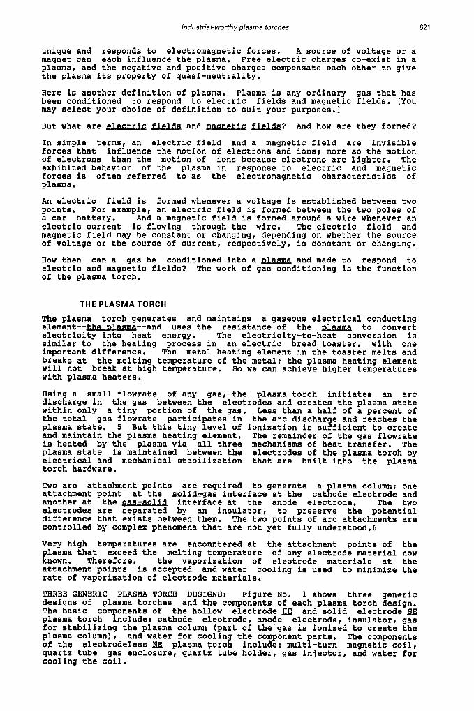
The Linde torch, Figure No. 3 , operates in the NT mode with two HE of equal diameters. [The early Linde designs had unequal electrode diameters like its older brother at HUlSp but the later models featured equal diameters.] The electrodes were fabricated from alloyed copper bars. Linde used a magnetic field coil to rotate the cathode attachment point. In many ways the Linde torch design and the Huls torch design are very similar, including the technique for starting the plasma column using a carbon-tip plunger.
The Linde torch design was later modified to operate in the reverse polarity connection. But with only a two percent gain in air enthalpy (from 38% of total input energy to 40% of input energy) the reverse polarity connection was not pursued vigorously. Another later modification permitted the Linde torch to operate in the transferred mode, Figure No. 4. The Retech Company of California is prototyping a titanium scrap remelting furnace using an improved Linde transferred arc torch design. See Table I1 below for additional information on the Linde-Retech torch design.
TABLE I1 -- Linde-Retech MODEL POWER RATING TYPICAL ARC VOLTS/ARC AMPS TYPICAL ARC GAS/FLOWRATE TYPICAL COOLANT/FLOWRATE TYPICAL ELECTRODE MATERIAL TYPICAL ELECTRODE LIFE DIA OF TORCH AT INSERTION PT WITH OR WITHOUT MAGNETIC COIL
RP-75T 100 Kw
200/500 HE/6 SCFM
WATER/3 GPM COPPER 100 HRS 89 MM w/o
RP-250" 300 Kw
230/1,400 HE/30 SCFM
WATER/30 GPM COPPER 150 HRS 140 MM w/o
RP-COOT 750 KW
250/3,000 AR/40 SCFM
WATER/110 GPM COPPER 200 HRS 235 MM w/o
There is no "Linde" torch, per 88, operating in an industrial plant. But I included this torch because I conducted many tests with a Linde torch design back in the mid-1960s and can substantiate its industrial worthiness at a power level of 8 mw. During the period of testing at NASA Ames Research Center, electrode life was not a significant factor, and I did not establish and confirm how long the electrodes would last. Several high- power Linde torch designs are still in operation at the NASA Laboratories. I included this design also for its parental image to other torch designs, e.g. Tioxide, PEC, Aerospatiale, Retech, etc.
THE WESTINGHOUSE TORCH: The plasma torch design of Westinghouse, Figure No, 5, is another one of the torch designs developed in response to the NASA requirements for high temperature air heaters. This plasma torch design has proven its industrial worthiness. It is operable with AC or DC power.
The Westinghouse plasma torch operates in the NT mode with HE made of alloyed copper. The electrodes are connected SPI rear electrode negative, when using DC power. The rear electrode is slightly larger than the front electrode, Westinghouse uses two magnetic field coils and rotates both arc attachment points. See Table I11 below for other information on the Westinghouse torch design.
TABLE I11 -- Westinghouse MODEL POWER RATING TYPICAL ARC VOLTS/ARC AMPS TYPICAL ARC GAS/FLOWRATE
TYPICAL ELECTRODE MATERIAL TYPICAL ELECTRODE LIFE DIA OF TORCH AT INSERTION PT WITH OR WITHOUT MAGNETIC COIL
TYPICAL COOLANT/FLOWRATE
MARC-3 150 kW
500/3 00 AIR/13 SCFM WATER/10 GPM
COPPER 150 HRS 3.5 IN
YES
MARC-11 2,000 kW
1,000/2,000 AIR/150 SCFM WATER/7O GPM
COPPER 200-600 HRS
8 IN YES
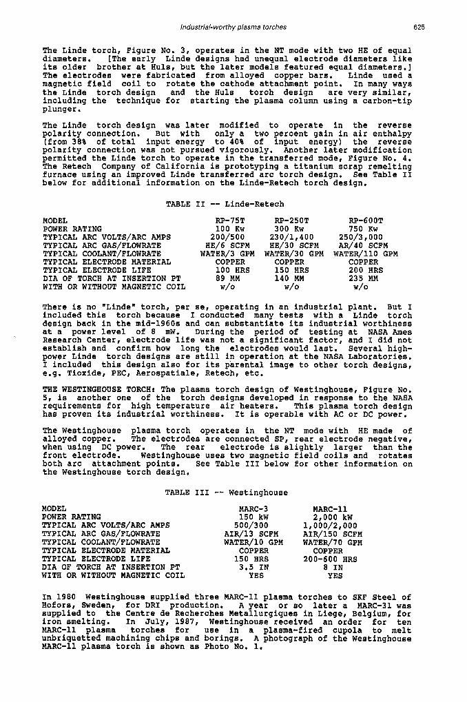
In 1980 Westinghouse supplied three MARC-11 plasma torches to SKF Steel of Hofors, Sweden, for DRI production. A year or so later a MARC-31 was supplied to the Centre de Recherches Metallurgiques in Liege, Belgium, for iron smelting. In July, 1987, Westinghouse received an order for ten MARC-11 plasma torches for use in a plasma-fired cupola to melt unbriquetted machining chips and borings. A photograph of the Westinghouse MARC-11 plasma torch is shown as Photo No. 1.
626 S. L. CAMACHO
PHOTO No. I
STANDARD A INT-HE-SP 1
...-...-...
B MULTI-SEGMENT I NT-HE-SP-SM I
TIOXIDE
FIGURE No. 6
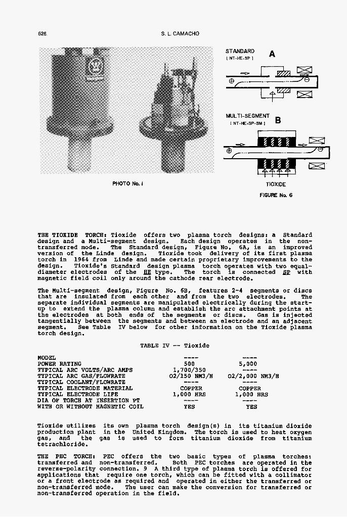
THE TIOXIDE TORCH: Tioxide offers two plasma torch designs: a Standard design and a Multi-segment design. Each design operates in the non- transferred mode. The Standard design, Figure No. 6A, is an improved version of the Linde design. Tioxide took delivery of its first plasma torch in 1964 from Linde and made certain proprietary improvements to the design. Tioxide's Standard design plasma torch operates with two equal- diameter electrodes of the = type. The torch is connected sp with magnetic field coil only around the cathode rear electrode.
The Multi-segment design, Figure No. 6B, features 2-4 segments or discs that are insulated from each other and from the two electrodes. The separate individual segments are manipulated electrically during the start- up to extend the plasma column and establish the arc attachment points at the electrodes at both ends of the segments or discs. Gas is injected tangentially between the segments and between an electrode and an adjacent segment. See Table IV below for other information on the Tioxide plasma torch design.
TABLE Iv -- Tioxide MODEL POWER RATING
TYPICAL ARC GAS/FLOWRATE
TYPICAL ELECTRODE MATERIAL TYPICAL ELECTRODE LIFE DIA OF TORCH AT INSERTION PT WITH OR WITHOUT MAGNETIC COIL
TYPICAL ARC VOLTS/ARC AMPS
TYPICAL COOLANT/FLOWRATE
---- 500
1 I 7 0 0/350 02/150 NM3/H
COPPER 1,000 HRS
YES
----
----
Tioxide utilizes its own plasma torch design(s) in its titanium dioxide production plant in the United Kingdom. The torch is used to heat oxygen gas, and the gas is used to form titanium dioxide from titanium tetrachloride.
THE PEC TORCH: PEC offers the two basic types of plasma torches: transferred and non-transferred. Both PEC torches are operated in the reverse-polarity connection. 9 A third type of plasma torch is offered for applications that require one torch, which can be fitted with a collimator or a front electrode as required and operated in either the transferred or non-transferred mode. The user can make the conversion for transferred or non-transferred operation in the field.

- lzZLlG ’.. . + @ /..-...-...-... -L.
PEC (A) I T-HE-RP I
FIGURE No. 7
Industrial-worth y plasma torches
PHOTO No. 2
627
The PEC plasma torch design for transferred mode operation, Figure No. 7A, has a copper rear electrode and a collimator. The function of the collimator is to collimate or focus the plasma arc column at the point that the column exits the plasma torch. The PEC plasma torch design for non-transferred mode operation, Figure No. 7B, has two copper electrodes: a capped rear electrode and an open tube front electrode, with an expanded diameter ’cup” that is used to stabilize the cathode attachment point. The electrode erosion pattern at the anode attachment point is radial and the erosion pattern at the cathode attachment point is axial. See Table V below for additional information on the PEC torches.
TABLE V -- PEC MODEL POWER RATING TYPICAL ARC VOLTS/ARC AMPS TYPICAL ARC GAS/FLOWRATE TYPICAL COOLANT/FLOWRATE TYPICAL ELECTRODE MATERIAL TYPICAL ELECTRODE LIFE DIA OF TORCH AT INSERTION PT WITH OR WITHOUT MAGNETIC COIL
PT-150 C# 250Kw
600/420 AIR/25 SCFM
WATER/25 GPM COPPER ALLOY
150 HRS 4.25 IN
w/o
PT-5 0 OT
900/5,000 N2/90 SCFM
WATER/100 GPM COPPER ALLOY
180 HRS 8.0 IN
4,500 KW
w/o #...The PT-15OC is a plasma torch with a “convertible” feature. The torch comes with a collimator for transferred mode operation and with a front electrode for non-transferred mode operation.
The PEC plasma torch design is used in prototype equipment, including: heating molten steel in a ladle for vertical and horizontal continuous casting machines, melting and consolidating titanium and nickel-base alloy scraps, smelting iron ore fines, heating oxygen for chemical reduction, recovering zinc from galvanizing plant wastes, etc. Photo. No.2 shows the PEC PT-500T plasma torch on a 150-ton Plasma Ladle Heater at Chaparral Steel in Texas.
TBE AEROSPATIALE TORCH: Aerospatiale (A/S) supplies a non-transferred torch design. The A/S plasma torch design, Figure No. 8, is similar to the Linde design that was supplied to the NASA Laboratories in the 1960s. A/S made improvements to the basic Linde torch design to achieve reasonable electrode life. The torch has a larger rear electrode than front
628 S. L. CAMACHO
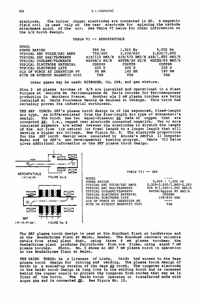
electrode. The hollow copper electrodes are connected in SP. A magnetic field coil is used only on the rear electrode for spinning the cathode attachment point of the arc. See Table VI below for other information on the A/S torch design.
TABLE VI -- AEROSPATIALE MODEL POWER RATING TYPICAL ARC VOLTS/ARC AMPS TYPICAL ARC GAS/FLOWRATE
TYPICAL ELECTRODE MATERIAL TYPICAL ELECTRODE LIFE DIA OF TORCH AT INSERTION PT WITH OR WITHOUT MAGNETIC COIL
TYPICAL COOLANT/FLOWRATE
300 KW 750/400
AIR/110 NM3/H WATER/4 M3/H
COPPER 400 H 95 MM YES
1,500 KW 5,000 KW 2,300/650 2,630/1p900
AIR/570 NM3/H AIR/l, 850 NM3/H WATER/2O M3/H WATER/60 NM3/H
COPPER COPPER 400 H 350 H 145 MM 165 MM YES YES
Other gases may be used: NITROGEN, CO, CH4, and gas mixture.
Nine 2 mW plasma torches of A/S are installed and operational in a Blast Furnace at Societe de Ferromanganese de Paris Outreau for ferromanganese production in Northern France. Another six 2 mW plasma torches are being installed at Hauts Fourneaux Reunis de Saulnes et Uckange. This torch has certainly proven its industrial worthiness.
THE SKF TORCH: SKF's plasma torch design is of the segmented, fixed-length arc type, as differentiated from the free-length arc type of Schoenherr's design. The torch has two equal-diameter HE made of copper that are connected Sp, i.e., capped rear electrode connected negative. Two or more insulated segments are added between the electrodes to stretch the length of the arc from its natural (or free) length to a longer length that will develop a higher arc voltage. See Figure No. 9. The electrode proportions for the SKF torch design were generated by Acurex's ARCFLO I1 Computer Model and by SKF's own developmental testing program. Table VII below gives additional information on the SKF plasma torch design.
AEROSPATIALE
I I NT-HE-SP I FIGURE No.8
m I
Wl
MODEL
TABLE VII -- 6KF . .~~~
POWER RATING TYPICAL ARC VOLTS/ARC AMPS TYPICAL ARC GAS/FLOWRATE TYPICAL COOLANT/FLOWRATE TYPICAL ELECTRODE MATERIAL TYPICAL ELECTRODE LIFE DIA OF TORCH AT INSERTION PT WITH OR WITHOUT MAGNETIC COIL
---- 6,000 - 7,000 kW
2,500-3,500/1,800-2,200 MIX #/1,000-1,500 NM3/H WATER/AppKOX 80 NM3/H
COPPER 100-600 HRS
YES ----
I SKF I NT-HE-SP-SM 1 FIGURE No. 9
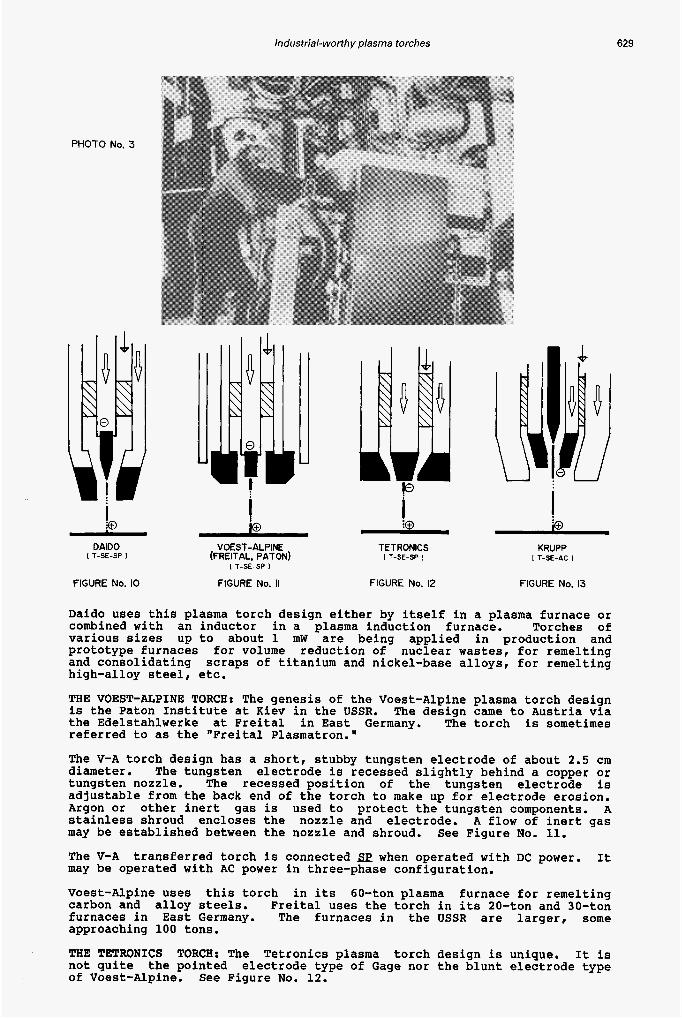
The SKF plasma torch design is used at the ScanDust Plant at Landskrona and at the Swedechrome Plant at Malmo, Sweden. The ScanDust recovers valuable metals from steel plant dust, using three 6 mW plasma torches; the Swedechrome plant produces ferrochrome from ore fines, using eight 7 mW plasma torches. Photo. No. 3 shows an SKF 7 mW plasma torch in operation at the Swedechrome Plant at Malmo.
THE DAIDO TORCH: As a licensee of Linde, Daido had access to the Gage plasma torch design €or cutting and welding. The plasma torch design of Daido is a scaled-up version of the Gage SE torch. The tungsten electrode in the Daido torch design is long like in the welding torch and is recessed behind the copper nozzle to protect the tungsten from oxides that may be in front of the torch. The Daido torch operates in transferred mode with argon gas and is connected Sp. See Figure No. 10.
Industrial-worth y plasma torches 629
PHOTO No. 3
DAIDO I T-SE-SP I
FIGURE No. 10
i 1 0
1 ! io @ - VOEST-ALPINE TETRONICS KRUPP
(FREITAL. PATON) I T-SE-SP 1 I T-SE-AC I I T-SE-SP I
FIGURE No. II FIGURE No. 12 FIGURE No. 13
Daido uses this plasma torch design either by itself in a plasma furnace or combined with an inductor in a plasma induction furnace. Torches of various sizes up to about 1 mW are being applied in production and prototype furnaces for volume reduction of nuclear wastes, for remelting and consolidating scraps of titanium and nickel-base alloys, for remelting high-alloy steel, etc.
THE VOEST-ALPINE TORCH: The genesis of the Voest-Alpine plasma torch design is the Paton Institute at Kiev in the USSR. The design came to Austria via the Edelstahlwerke at Freital in East Germany. The torch is sometimes referred to as the "Freital Plasmatron."
The V-A torch design has a short, stubby tungsten electrode of about 2.5 cm diameter. electrode is recessed slightly behind a copper or tungsten nozzle. The recessed position of the tungsten electrode is adjustable from the back end of the torch to make up for electrode erosion. Argon or other inert gas is used to protect the tungsten components. A stainless shroud encloses the nozzle and electrode. A flow of inert gas may be established between the nozzle and shroud.
The V-A It may be Operated with AC power in three-phase configuration.
Voest-Alpine uses this torch in its 60-ton plasma furnace for remelting carbon and alloy steels. Freital uses the torch in its 20-ton and 30-ton furnaces in East Germany. The furnaces in the USSR are larger, some approaching 100 tons.
THE TETRONICS TORCH: The Tetronics plasma torch design is unique. It is not quite the pointed electrode type of Gage nor the blunt electrode type of Voest-Alpine. See Figure No. 12.
The tungsten
See Figure No. 11.
transferred torch is connected sp when operated with DC power.

630 S. L. CAMACHO
The Tetronics plasma torch operates in the transferred mode connected in sp. The tungsten electrode is not recessed. The electrode is protected by the flow of inert gas through a narrow annular area formed by the electrode and nozzle.
The Tetronics plasma torch design has proven its industrial worthiness in several applications. Texasgulf commissioned a production plant in Alabama, USA, to recover platinum group metals from automobile catalysts. The plasma furnace at Texasgulf uses a Tetronics 3 mW plasma torch. A smaller torch is used in Japan for heating molten steel in a tundish. And a 1.5 MVA prototype furnace is being tested in the United Kingdom.
THE KRUPP TORCH: The Krupp plasma torch design is an torch for AC operation. Three torches are used in three-phase configuration. The steel scrap being melted serves as the common electrode or connection point for the three plasma torches. I included this torch among the solid electrode torch because the electrode is for all practical purposes a solid.
The unique features of the Krupp plasma torch are the techniques for starting and stabilizing the plasma arc column. For starting the torch, a hole is drilled in the middle of the electrode. A small solid tungsten rod is position inside the hole and is properly insulated from it. DC power is connected sp between the solid rod and the electrode, i.e., the rod is negative, and the electrode is positive,
The plasma discharge between the rod and the electrode serves as pilot arc to start the main arc between the torch and scrap charge. And the existence of the continuous plasma discharge of the pilot arc serves to stabilize the main arc column, as the current passes through zero and reverses direction 50-60 times per second. A protective shroud surrounds the main electrode. See Figure No. 13.
By operating three torches in AC configuration, Krupp eliminated the requirement for an external electrode. The flow of arc current is via the plasma column of one torch to the scrap charge, through the scrap charge, and via the plasma column from the scrap charge to another torch.
The Krupp plan for developing the ,$g plasma torch design is meticulous and they have achieved their goals and objectives. The Krupp design promises many benefits for plasma processes.
Krupp is presently testing its torch design in a 10-ton, 10-mW plasma furnace and is developing larger torches for bigger furnaces. The Krupp plasma torch design is being considered for ladle heating application.
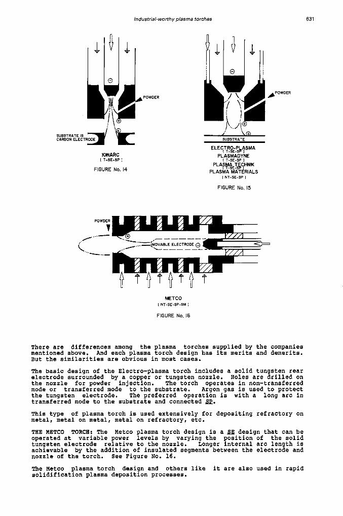
THE IONARC TORCH: The IONARC plasma torch design has many merits. And the success of the design highlighted many of the benefits of using plasma in materials production. See Figure No. 14.
There is a resemblance between the IONARC torch design and Gage's B torch design for cutting and welding: tungsten rod electrode, nozzle, sp connection to an external electrode, Argon gas to protect the tungsten, etc. But the similarity ends here.
IONARC added holes on the nozzle for introducing powdered materials. And to extend the residence time of the powder with the plasma, a long arc was established to external graphite electrodes. The graphite electrodes were positioned in such a way as to minimize the deflection of the arc column and maximize the plasma-powder interactions. The graphite electrodes were rotated and fed into the center as they were consumed.
Multiple plasma reactors of 350 kW have been producing zirconium dioxide from zircon sand since 1978. The focused of attention to plasma-reaction engineering has been the key to the success of this chemical process.
THE ELECTRO-PLASMA TORCH: The target applications for the Electro-Plasma torch design and other designs like it is rapid solidification plasma deposition processes. This Gage-type of torch is operated in transferred mode to a substrate. Powder material fed into the nozzle of the torch is heated and reacted in-flight and deposited on the substrate. See Figure No. 15.
Other suppliers offer similar plasma torch designs. The list includes: Plasmadyne, Plasma Technik, Plasma Materials, and others.
Industrial-worth y plasma torches 63 1
SUBSTRATE IS
IONARC I T-SE-SP I
FIGURE No. 14
..A
L. ..-
POWDER
7 ...-
1 \a SUBSTRATE
ELECfTfQ~$bfSMA PLASMADYNE
I T-SE-SP I PLAF#E$YHNIK
PLASMA MATERIALS I NT-SE-SP I
FIGURE No, 15
METCO I NT-SE-SP-SM I
FIGURE No. 16
There are differences among the plasma torches supplied by the companies mentioned above. And each plasma torch design has its merits and demerits. But the similarities are obvious in most cases.
The basic design of the Electro-plasma torch includes a solid tungsten rear electrode surrounded by a copper or tungsten nozzle. Holes are drilled on the nozzle for powder injection. The torch operates in non-transferred mode or transferred mode to the substrate. Argon gas is used to protect the tungsten electrode. The preferred operation is with a long arc in transferred mode to the substrate and connected sp.
This type of plasma torch is used extensively for depositing refractory on metal, metal on metal, metal on refractory, etc.
THE METCO TORCH: The Metco plasma torch design is a SE design that can be operated at variable power levels by varying the position of the solid tungsten electrode relative to the nozzle. Longer internal arc length is achievable by the addition of insulated segments between the electrode and nozzle of the torch. See Figure No. 16.
The Metco plasma torch design and others like it are also used in rapid solidification plasma deposition processes.

632 S. L. CAMACHO
SUMMARY
We started out with an introduction to plasma phenomena. This lead us to answering the questions: what is plasma? how do we initiate it? how do we maintain it? With a fair understanding of the phenomena of the plasma state, we proceeded to design a plasma torch and became familiar with the essential components that make up a plasma torch: ELECTRODES, which may be solid or hollow copper or other metals; INSULATORS, which may be filled teflon or ceramic, and whose function is to insulate one electrode from the other so that electric forces may be established between them; tangential GAS INJECTORS, to create a gas vortex that will stabilize the plasma column; COOLANT, which may be water at the correct pH level or ethylene glycol; and MAGNETIC COIL to spin the arc attachment.
We learned that very high temperatures are encountered at the two gas-solid interfaces where the plasma column attaches to the solid electrodes of the plasma torch, The temperatures encountered are beyond the melting point of any known metal, and we accepted to experience erosion of the electrode material at the attachment points. The rate of erosion determines the life of the electrodes, and hence the life of the torch. We learned that tangential gas injection and magnetic rotation reduce the rate of electrode erosion.
I presented and discussed the physical designs and the operating characteristics of nearly two dozen plasma torches that are employed in industry today. I tried to introduce the different designs according to my recollection of historical perspectives, with the hope that your understanding of the technology and its potential benefits may be enhanced by them.
It was not my objective to make plasma experts of you. Rather, I want to familiarize you with what plasma torches are available for you to use in your processes. I encourage you to concentrate on the development of your process and leave the development of the plasma torch to the torch experts. I realize that in some cases the two cannot be treated separately.
Plasma torch technology is developing rapidly and I may have missed some important considerations. If I did, I apologize to you and to the suppliers.
REFERENCES
1-0. Schoenherr, Electrotechnik Zeitschrift, 30, 365 (1909). 2-K. Birkeland, -he O M o n of- in ElectricArcs Transactions of the Faraday Society, 2 (1906). 3-R. M. Gage, of the.nodern Arc Ton& , Welding Journal, 38 (1968). 4-A. E. Mensing, L. R. Boedeker, Theoretical Invest- RF Induction m t e d NASA CR-1312 (1969). 5-L. I. Kolonina, V. Ya. Smolyakov of an Arc Colum.~ in a
Fiziki, (19651, 6-E. Pfender, M. Boulos, P. Fauchais of Pllasma Generation Chapter 4, PLASMA TECHNOLOGY IN METALLURGICAL PROCESSING (1987). 7-M. L. Thorpe, L. W. S c a t , NASA CR-1343, May (1969). 8-L. Kerker, R MUller, m a G a a , Stahl a (1987).
Translation from Zhurnal Prikladnof Mekhaniki i Tekhnicheskoi * .
s for Productionsf
9-S. L. Camacho, Reverse - P- Tor& 369, ISPC-8, Tokyo,