Embed Size (px)
Citation preview
INDUSTRIAL TRANSESTERIFICATIONOF CULTIVATED ALGAE FOR BIOFUEL
Item Type text; Electronic Thesis
Authors LaRue, Kate; Balch, Brian; Jabczynski, Chris; Swensen, Connor
Publisher The University of Arizona.
Rights Copyright © is held by the author. Digital access to this materialis made possible by the University Libraries, University of Arizona.Further transmission, reproduction or presentation (such aspublic display or performance) of protected items is prohibitedexcept with permission of the author.
Download date 05/06/2018 23:21:38
Link to Item http://hdl.handle.net/10150/613238
INDUSTRIAL TRANSESTERIFICATION OF CULTIVATED ALGAE FOR
BIOFUEL
By
KATE LARUE
____________________
A Thesis Submitted to the Honors College
In Partial Fulfillment of the Bachelors degree With Honors in
Chemical Engineering
THE UNIVERSITY OF ARIZONA
M A Y 2 0 1 6
Approved by:
____________________________
Dr. Kim Ogden Department of Chemical Engineering
Summary
The main objective of this report is an experimental design for an industrial processing of
algae grown on-site to create a methyl ester based biofuel. The sub-objectives of the plant were
to design a process that is as environmentally friendly and as self-sustainable as possible.
The alternative energy market is a new and growing industry as the need to find
alternatives to petroleum-based fuel continuously increases. At the right growth conditions, three
strains of algae are cultivated in a series of algae photobioreactors utilizing natural sunlight and
nutrients. For the design of the plant, lipids will be extracted from algae using supercritical
carbon dioxide in replace of cyclohexane, and the triglycerides extracted from algae will be
subject to a base-catalyzed transesterification reaction, using methanol as a reagent in order to
form glycerol and the desired methyl esters used as an alternative combustible fuel. The reaction
yields a 99% pure methyl ester-based product and 97-98% pure glycerol product. Total
production results in 831 barrels per day, resulting in a total yearly production of 274,207 barrels
of fuel assuming 330 days of production. An economic analysis of the plant design calculated a
required total capital investment of $44,737,746 in order to fabricate the plant from scratch.

8
9
Group member contribution overview
Brian Balch
Process Description
CSTR Sizing
Transesterification Reaction/Catalyst
Chris Jabczynski
LLE sizing
Distillation Tower Sizing
Economics
Kate LaRue
SCCO2 Separation/Recycle
PFD
Safety/Environmental Factors
Connor Swensen
SCCO2 Extractor Sizing/Costing
Plant Location and Utilities
Appendices and References
10
Table of Contents
Section 1 Introduction/Background
1.1 Overall Goal…………………………………………………………………………...1
1.2 Current Market Information…………………………………………………………...1
1.3 Project Premises and Assumptions …………………………...……………………....2
Section 2 Process Description, Rationale and Optimization
2.1 Overall Process Description…………………………………………………………..4
2.2 Rationale for Process Choice………………………………………………………...23
Section 3 Equipment Description, Rationale and Optimization
3.1 Algae Reactor………………………………………………………………………...26
3.2 Supercritical carbon dioxide solid-liquid extractor…………………………………..27
3.3 Transesterification CSTRs…………………………………………………………...28
3.4 Catalyst Filtration…………………………………………………………………….29
3.5 Liquid-liquid extractor……………………………………………………………….30
3.6 Flash/stage distillation columns……………………………………………………...30
Section 4 Safety and Environmental Factors
4.1 General Plant Considerations………………………………………………………...32
4.2 Personal Protection Equipment………………………………………………………32
4.3 Major Equipment Hazard Operation…………………………………………………32
4.4 Chemical Storage Hazards…………………………………………………………...34
4.5 Environmental Impact Assessment…………………………………………………..35
Section 5 Economic Analysis including Economic Hazards…………………………………….37
Section 6 Conclusion and Recommendations……………………………………………………42
Section 7 References……………………………………………………………………………..44
Section 8 Appendix
A. Process Flow Diagrams
A.1 Process Flow Diagram for Algae Bioreactors……………………………………….47
A.2 Process Flow Diagram for Plant Transesterification………………………………..48
B. Block Flow Diagram
11
B.1 Block Flow Diagram for Algae Bioreactors………………………………………...49
B.2 Block Flow Diagram for Plant Transesterification………………………………….50
C. Flow Stream Tables
C.1 Stream Tables for Algae Bioreactors………………………………………………..51
C.2 Stream Tables for Plant Transesterification…………………………………………52
D. Nomenclature…………………………………………………………………………….55
E. Equipment calculations
E.1 Algae Reactor………………………………………………………………………..57
E.2 Supercritical Extractor.................................................................................................58
E.3 CSTR………………………………………………………………………………...60
E.4 LLE…………………………………………………………………………………..62
E.5 Distillation Columns…………………………………………………………………64
E.6 Pumps………………………………………………………………………………..68
F. Economics Calculations………………………………………………………………….70
G. Vendor Information
G.1 Supercritical Extractor................................................................................................72
G.2 Algae Nutrient.............................................................................................................75
G.3 Potassium Carbonate...................................................................................................76
G.4 Methanol…………………………………………………………………………….77
G.5 Glycerol……………………………………………………………………………...78
G.6 Slurry………………………………………………………………………………...79
H. Hazards and Operability Review
H.1 Algae Photobioreactor HAZ OP…………………………………………………….80
H.2 Supercritical Extractor HAZ OP…………………………………………………….84
H.3 CSTR HAZ OP……………………………………………………………………...87
H.4 Distillation Towers HAZ OP………………………………………………………..89
I. Meeting minutes…………………………………………………………………………...91
Section 1 Introduction/Background
1.1 Overall Goal
The objective of the design was to create a chemical plant that uses cultivated algae
grown on-site in order to produce a biofuel as an alternative energy source. Currently there is a
push for sustainable energy sources, and biologically produced fuels are attractive due to their
near net-zero carbon emissions. Algae provides a valuable source of energy due to its growth rate
and sustainability. Chemical engineering principles were utilized in this design; a supercritical
carbon dioxide extractor for the triglycerides in the algae cells, base-catalyzed transesterification
reaction in continuously stirred reactors in series, and separation processes at the end in order to
produce a high-grade biofuel for consumer applications. Emphasis on environmental
consideration also went into the design. For example, carbon dioxide was used for the extraction
process, and methanol was used for the transesterification and liquid extraction. This allowed for
easy recycle and further reduces the environmental footprint the fuel produced will have.
274,207 barrels of fuel of 99% pure methyl ester-based product is produced per 330 days. The
glycerol side product produced is of 97-98% purity.
1.2 Current Market information
The current market for biofuel is relatively new in comparison to the established market
for petroleum-based products. Based on an Environmental Entrepreneurs (E2) executive
summary regarding the future of biofuel, the capacity in 2014 was approximately 800 million
gallons of gasoline-equivalent fuel, and it is predicted that by 2017, it may reach over 1.7 billion
gallons equivalent (Advanced Biofuel Market Report). Under E2 standards, algae-based biofuels
are still awaiting United States Environmental Protection Agency (EPA) approval and therefore
have not been established as a market standard. However, the product produced is nearly
identical to its biodiesel cousins (Alternative Fuel PriceReport).
The most recent report by the United States Department of Energy in January 2016 puts
B99/B100 (indicating 99 to 100% purity) at $3.21 a gallon ("Clean Cities: Alternative Fuel Price
Report). This grade biodiesel is the target to reach due to its large consumer-grade use rather
than pure industrial use. In the same report for a basis, gasoline is $1.98 a gallon, which currently
2
is a much cheaper alternative. However, previous history shows that in the United States, in July
of 2008, gasoline prices reached a high of $4.11 a gallon, which is currently higher than the
current gallon price of biodiesel. While the oil market fluctuates rapidly, more due to political
and social reasons rather than technological, it is hard to predict future price points. The limited
availability and increasing demand for fuel will eventually bring the price point back up to a
position where biodiesel can become more competitive. In the meantime, as technological
advances increase in the alternative fuel industry, whether it be for political or economic reasons,
the processes behind creation of biofuel will become cheaper and more efficient with time,
lowering the cost needed to create a profit. Algae biofuel serves as a new option in the alternative
fuel industry, with its key strength being in its nearly limitless renewability (Campbell).
While the goal of the plant design was to propose a new method of creation of a
renewable fuel for consumer consumption, certain limitations were imposed on the design. The
current market for biofuel-based products is much lower than standard petroleum-based
products, meaning that the feasibility of the economic design of biofuel end product is highly
unlikely. The plant design is a proof of chemical engineering concepts, where at some point
down the line, the technologies and processes used in algae refinement will decrease initial
investment required, creating an easier product to sell. Additionally, the price of petroleum-based
fuel will continue to rise, and a break-even point will eventually occur allowing this process to
be very competitive in a market setting.
1.3 Project Premises and Assumptions
Because the scale of the industrial design has not been created before, the data and
research used for the basis of assumption is scaled off of bench-level and idealized conditions.
While countermeasures were taken in terms of modeling mechanical and chemical efficiencies,
the end result is still very much in theory and cannot be taken as an exact design. Modeling of
algae growth, as well as specific composition of each strain of algae, could only be estimated as
a percent average of its dry weight, meaning the total mass entering the process could be higher
or lower depending on the strain. Even after the transesterification reactor, an average value of
potential methyl esters is assumed due to the uncertainty of the molecular weight of the
3
triglycerides entering. Based off of the most common fatty acid chains attached to a glyceride, a
weight of 882 g/mol was assumed for all triglycerides entering. For methyl esters produced, an
average weight was calculated of 274 g/mol and used for exiting reactor streams (Excel Sheet,
'CSTR Design').
The supercritical carbon dioxide extraction, due to the process only researched in smaller
scale settings, was assumed to transfer ideally and have a 100% recovery rate after extracting the
triglycerides from the algae (Appendix E.2). Additionally, a ratio of supercritical carbon dioxide
needed per amount of algae was assumed from a small-scale design of 400 mL/min of
supercritical carbon dioxide per 2.4 g of algae (Halim). After industrial considerations, that ratio
was adjusted to 5e-6 m3/hr of supercritical carbon dioxide per 0.001 kg of algae (Appendix E.2).
Because a literature ratio could only be found for powdered-algae, it was decided with an expert
in the field of algae to keep the ratio with an additional water stream (Facilitator Meeting
Minutes, March 9, 2016). Any ChemCad simulations used to model the triglycerides and methyl
esters used arachadic acid due to its similar molecular weight and elemental structure (Facilitator
Meeting Minutes, March 9, 2016).
Because the experimental design was not partnered with a current company or process
design, pipe sizing was assumed to be negligible (Mentor Meeting Minutes, April 6, 2016). This
assumption prompted an additional assumption in regards to the head for each particular pump.
Because head loss depends on pipe length, and therefore velocity and diameter, an assumed
value of 250 ft was used in regards to pump costing. This average value is taken from a head
range that corresponds to the lowest flow rate range of 50-900 gallons per minutes that satisfies
pump and pipe conditions. Therefore, a kilowattage of 3,356 kilowatts per hour is assumed
(Appendix E.6)
4
Section 2 Process Description, Rationale and Optimization
2.1 Stream and Equipment Process Description
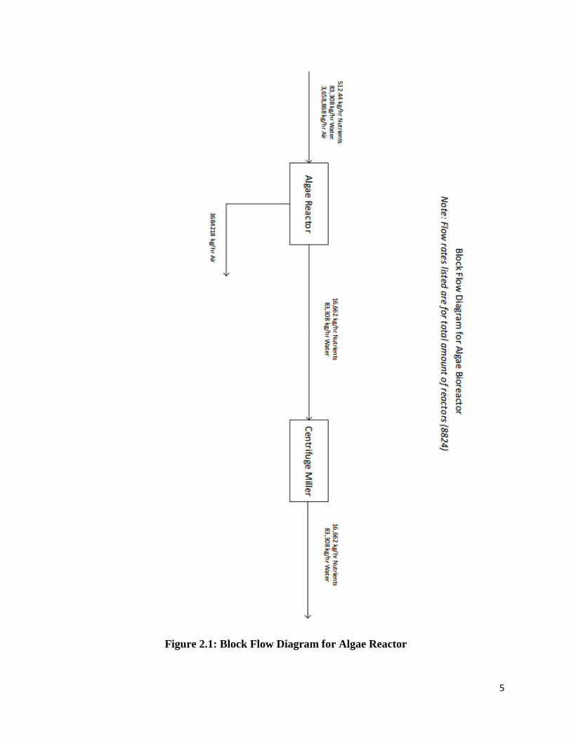
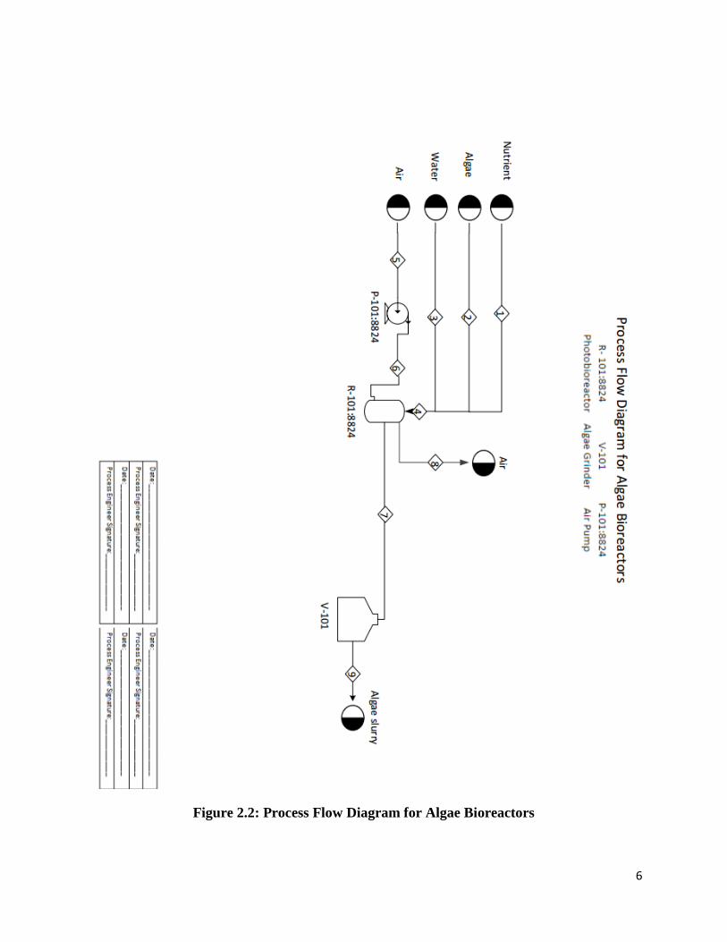
A block flow diagram is provided in Figure 2.1, and a detailed process flow diagram with
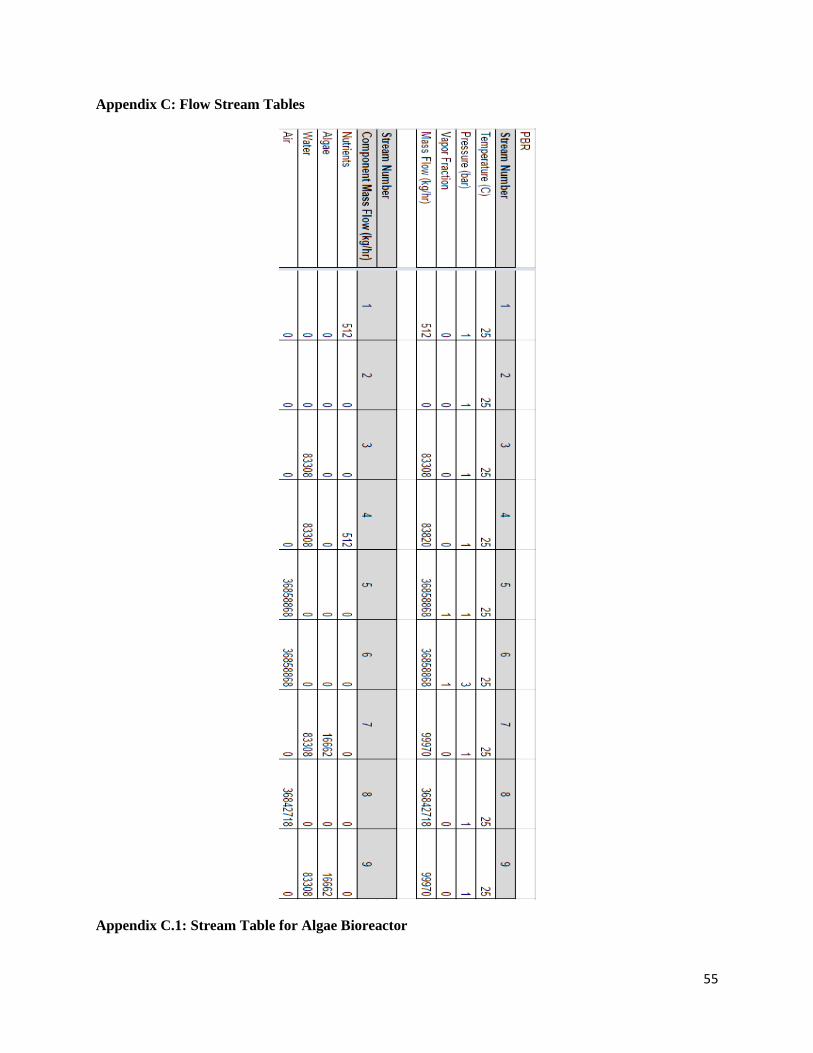
equipment labeling and stream numbers is provided in Figure 2.2. Stream and flow rate tables for
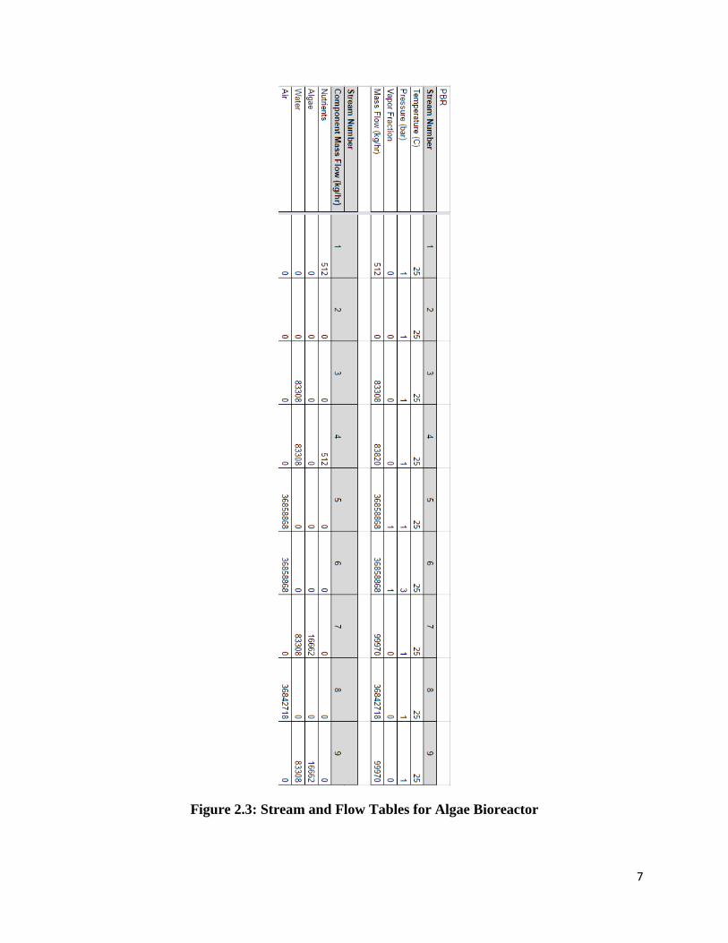
the algae reactors are provided in Figure 2.3. All references are also located in Appendix A.
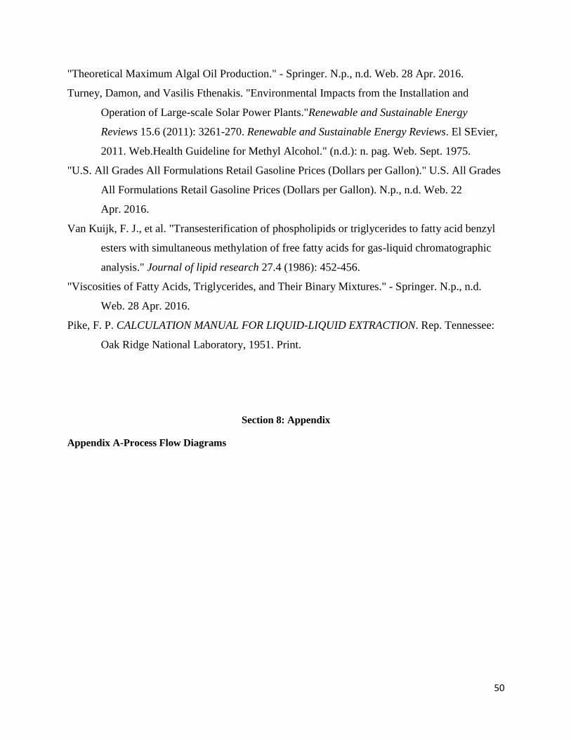
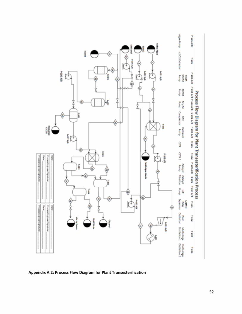
The start of the process involves the growth of cultivated algae on-site. Choice of algae
strains and growth rate is detailed in Section 3. The total algae farm is composed of 8,824
reactors to grow and harvest the algae (R-101:8824). A total flow rate for all 8,824 reactors
involves 3,658,868 kg/hr of air (Stream 6), 512 kg/hr of a nutrient mixture (Stream 1), and
83,308 kg/hr of water (Stream 3). The nutrient mixture is composed of various nitrogen and
potassium-based compounds to foster algae growth. After a growth period for the algae, the
reactors are drained into a centrifuge miller (V-101) in order to create a crushed algae slurry
composed of 16,662 kg/hr algae as an ultimate total of all reactors, as well as the 83,308 kg/hr of
water drained from the reactor, creating an approximate 20:80 ratio of algae to water (Stream 9).
5
Figure 2.1: Block Flow Diagram for Algae Reactor
6
Figure 2.2: Process Flow Diagram for Algae Bioreactors
7
Figure 2.3: Stream and Flow Tables for Algae Bioreactor
8
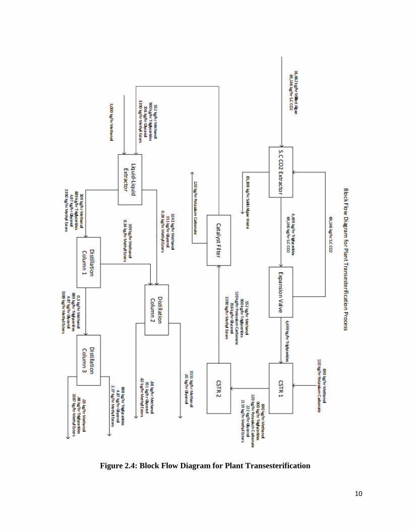
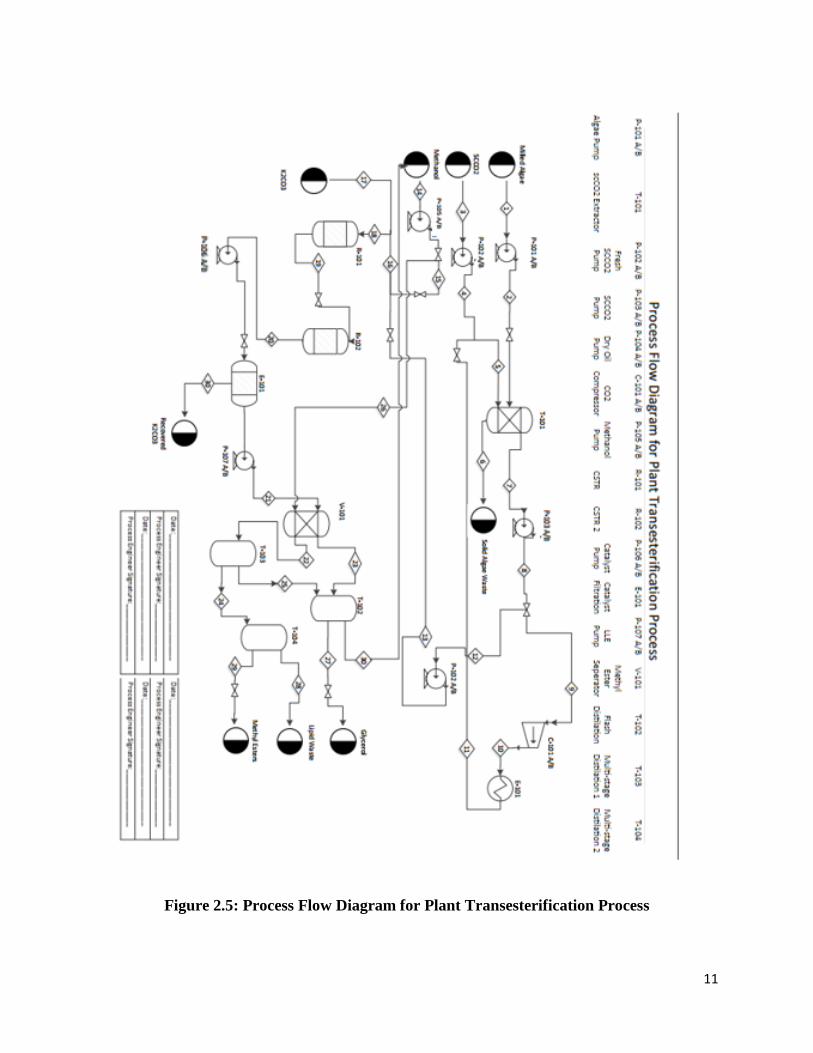
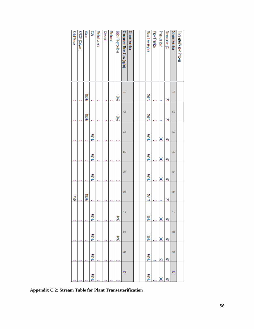
Stream 9 then feeds into the transesterification process design. Block flow and process
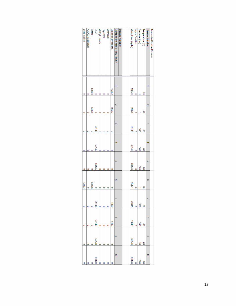
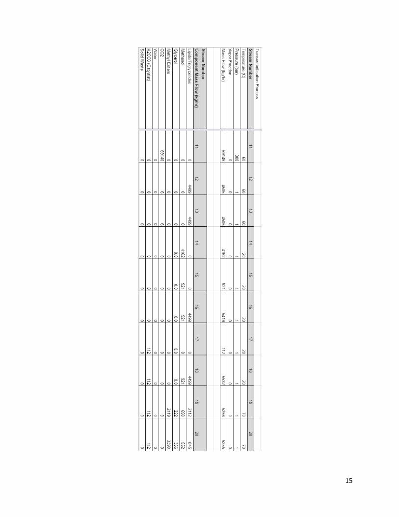
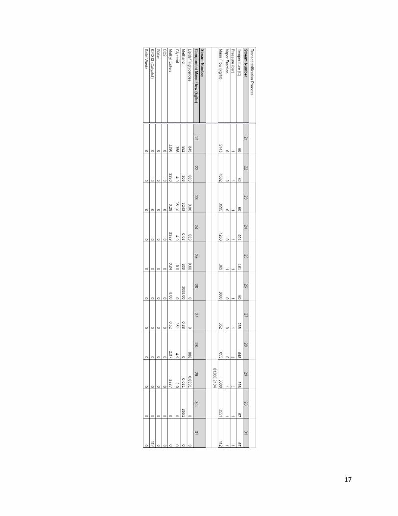
flow diagrams are referenced in Figure 2.4 and Figure 2.5. Stream and flow characteristics are
referenced in Figure 2.6.
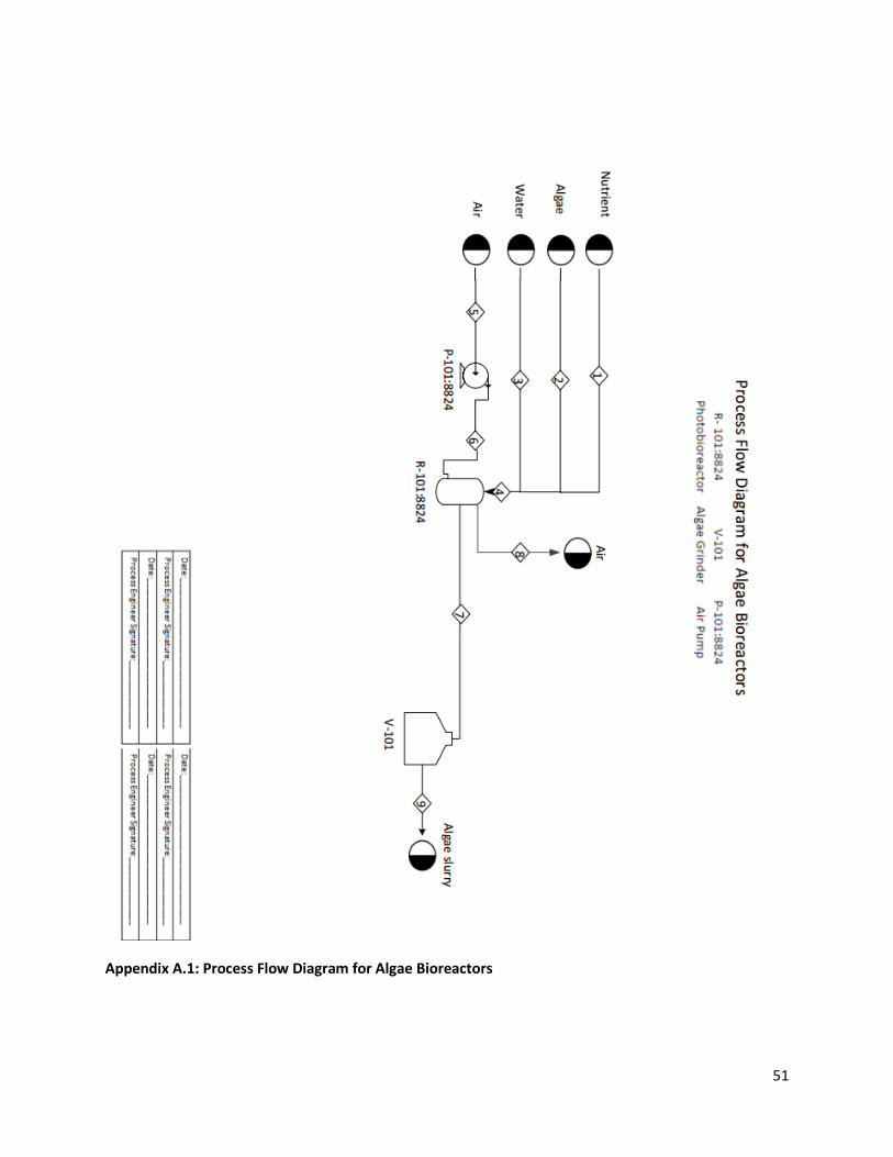
The slurry (Stream 1) is then fed to a supercritical carbon dioxide (SCCO2) extractor (T-
101) in order to separate out the various lipids and triglycerides from the solid waste, water, and
non-organic components from the slurry. SCCO2 enters the reactor (Stream 5), composed of
fresh SCCO2 feed from the on-site storage (Stream 4) and from recycled SCCO2 from further
down the process (Stream 11) at 69,146 kg/hr. The composition of the stream entering the
reactor is 16,662 kg/hr of lipids and triglycerides and 83,308 kg/hr of water, approximately a
20/80 ratio. The lipids and triglycerides leave the process (Stream 7) while the wastewater and
non-organic components are classified as waste (Stream 6).
The triglyceride/lipid and carbon dioxide stream then reaches an expansion valve along
the line that releases the carbon dioxide out of its supercritical state and into the gas phase
(Stream 8). The valve operates purely off the change of phase of supercritical fluid to gas, where
the liquid phase lipids exit through a bottom stream (Stream 12) and the gas phase carbon
dioxide exits through the top (Stream 9). From the top stream, the carbon dioxide gas is then fed
to a compressor in order to recycle the carbon dioxide back into a supercritical state. It then
recycles back into the initial extractor (Stream 5).
The lipid/triglyceride stream (Stream 18) feeds into an initial continuously stirred reactor
(CSTR) at 4,499 kg/hr, for a transesterification reaction (R-101/102). The reactant driving the
process is methanol, fed in at 4,162 kg/hr (Stream 14) with triglycerides to form glycerol and
methyl esters as products. Methanol fed into the first CSTR, along with the addition of solid
potassium carbonate as a catalyst (Stream 17), reacts to a conversion of 0.5. After leaving the
first reactor, the stream feeds into a second CSTR (Stream 19), with more methanol added, in
order to maximize the conversion of the methyl esters for a final conversion of 0.8. The final
reacted stream leaves the second CSTR (Stream 20) and is pumped through an industrial filter to
filter out the unreacted solid catalyst for reuse in the process (E-101) (Stream 30).
The reacted mixture is then sent to a liquid-liquid extractor (LLE) using methanol as a
solvent (V-101) (Stream 26). The methanol solvent is fed from a feedstock shared with the
9
CSTR (Stream 21). The current composition of the stream entering the LLE is a mix of 845 kg/hr
unreacted triglycerides, 552 kg/hr of excess methanol, 356 kg/hr of glycerol, and 3390 kg/hr of
methyl esters. Leaving the extractor through the top is a mixture of 3,243 kg/hr methanol and
351 kg/hr of glycerol, which will then head to a distillation column (T-102) (Stream 23). The
bottoms of the LLE is a stream composed of 889 kg/hr of unreacted triglycerides and lipids,
3,390 kg/hr of various methyl esters, and trace amounts of methanol and glycerol (Stream 22).
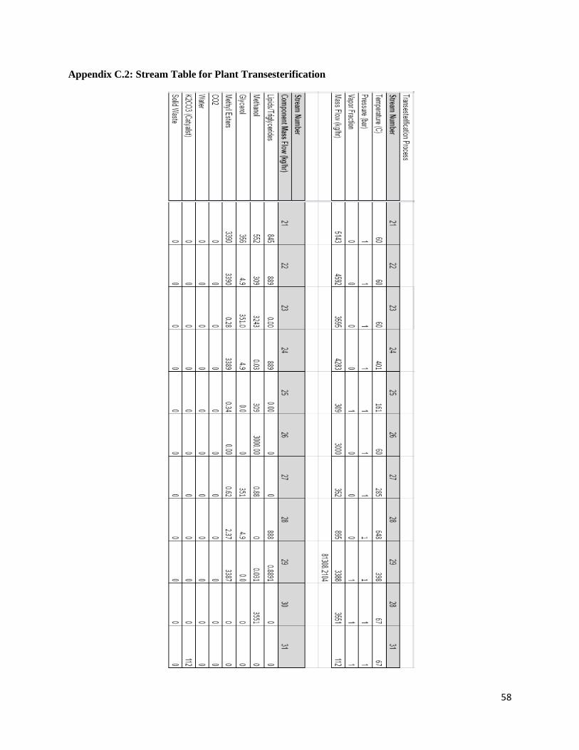
Exiting the LLE, stream 23 flows to a distillation column (T-102). The distillation
separates the two components, with the bottom stream yielding 351 kg/hr of glycerol (Stream
27), and the top stream of 3551 kg/hr excess processed methanol (Stream 30), which is then
recycled back into the process for use as both a reagent for the reaction and as a solvent for the
previous LLE operation. The bottoms stream (Stream 22) from the LLE feeds to distillation
column T-103, where an initial separation takes place. The resulting distillate (Stream 23) is
composed of 309 kg/hr of methanol and feeds into T-102. The bottoms (Stream 24) is composed
of a composition of unreacted triglycerides and lipids as well as the methyl ester product. This
stream feeds into T-104, where the final separation takes place. The distillate (Stream 28), is
composed of 888 kg/hr of unusable lipids and unreacted triglycerides, as well as trace amounts of
glycerol. The bottoms of the tower (Stream 29) yields a stream of 3551 kg/hr of methyl esters
with a purity of ~99%, which is used to sell as a B99/100 fuel grade. With the flow rate yield, the
production of the facility results in 831 barrels per day of methyl ester-based fuel (Excel ‘LLE
and Distillation’).
10
Figure 2.4: Block Flow Diagram for Plant Transesterification
11
Figure 2.5: Process Flow Diagram for Plant Transesterification Process

12
13

14
Figure 2.6: Flow and Stream Tables for Transesterification Process
15

16
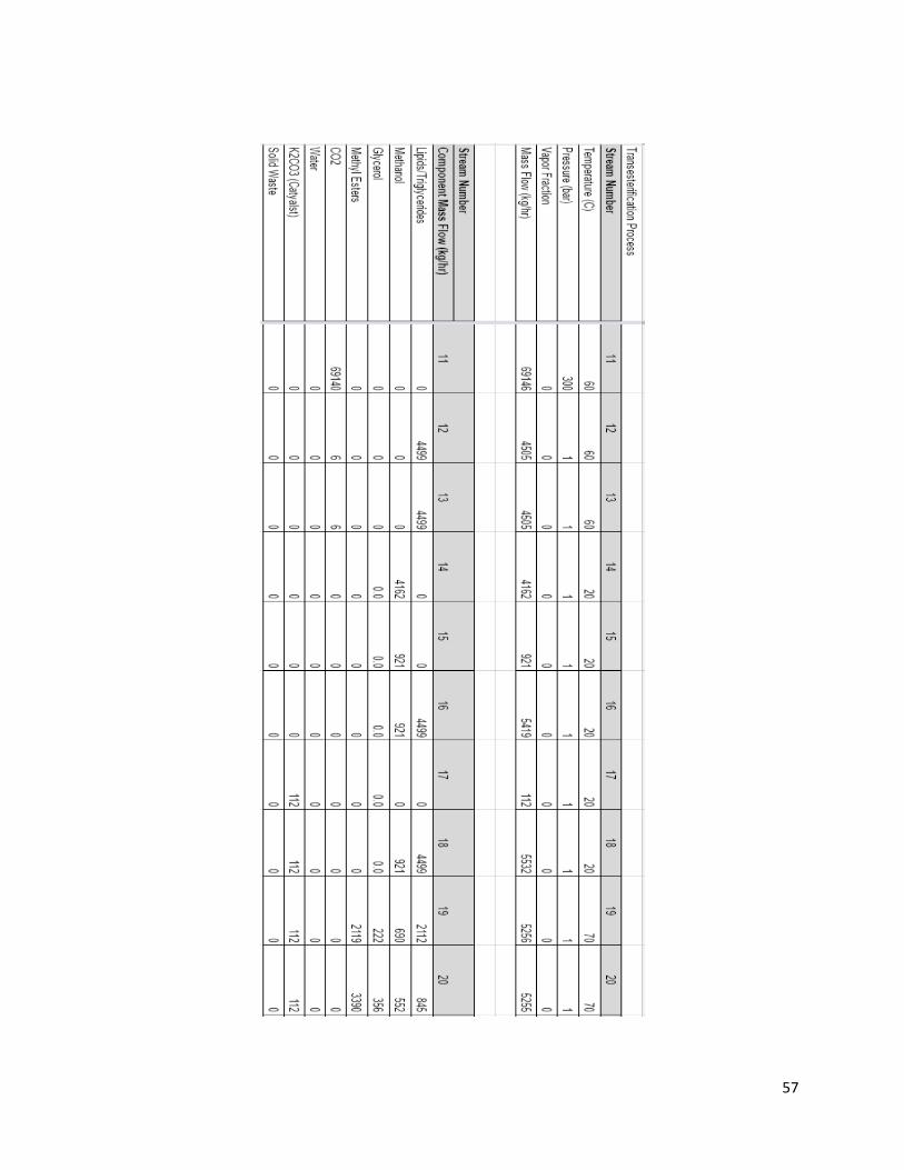
Figure 2.6: Flow and Stream Tables for Transesterification Process
17
18
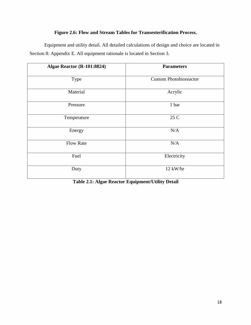
Figure 2.6: Flow and Stream Tables for Transesterification Process.
Equipment and utility detail. All detailed calculations of design and choice are located in
Section 8: Appendix E. All equipment rationale is located in Section 3.
Algae Reactor (R-101:8824) Parameters
Type Custom Photobioreactor
Material Acrylic
Pressure 1 bar
Temperature 25 C
Energy N/A
Flow Rate N/A
Fuel Electricity
Duty 12 kW/hr
Table 2.1: Algae Reactor Equipment/Utility Detail
19
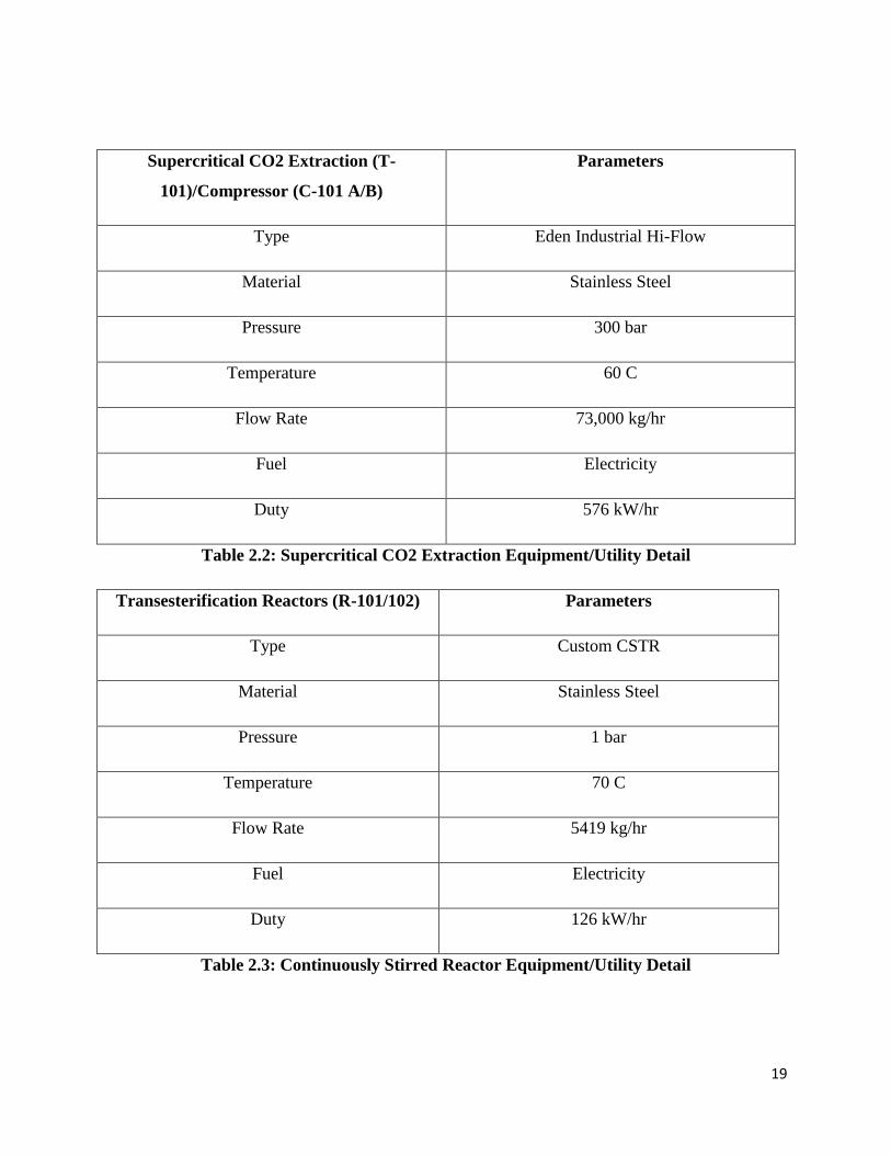
Supercritical CO2 Extraction (T-
101)/Compressor (C-101 A/B)
Parameters
Type Eden Industrial Hi-Flow
Material Stainless Steel
Pressure 300 bar
Temperature 60 C
Flow Rate 73,000 kg/hr
Fuel Electricity
Duty 576 kW/hr
Table 2.2: Supercritical CO2 Extraction Equipment/Utility Detail
Transesterification Reactors (R-101/102) Parameters
Type Custom CSTR
Material Stainless Steel
Pressure 1 bar
Temperature 70 C
Flow Rate 5419 kg/hr
Fuel Electricity
Duty 126 kW/hr
Table 2.3: Continuously Stirred Reactor Equipment/Utility Detail
20
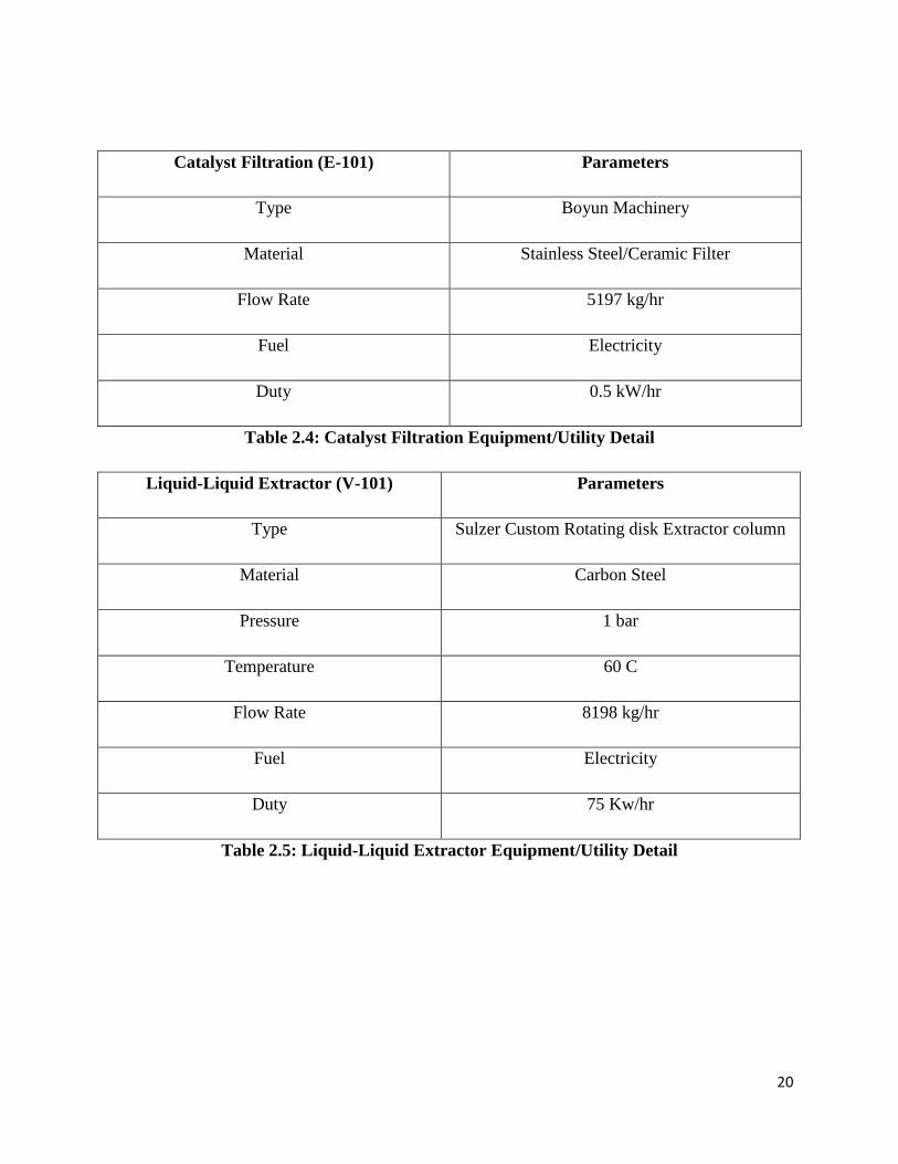
Catalyst Filtration (E-101) Parameters
Type Boyun Machinery
Material Stainless Steel/Ceramic Filter
Flow Rate 5197 kg/hr
Fuel Electricity
Duty 0.5 kW/hr
Table 2.4: Catalyst Filtration Equipment/Utility Detail
Liquid-Liquid Extractor (V-101) Parameters
Type Sulzer Custom Rotating disk Extractor column
Material Carbon Steel
Pressure 1 bar
Temperature 60 C
Flow Rate 8198 kg/hr
Fuel Electricity
Duty 75 Kw/hr
Table 2.5: Liquid-Liquid Extractor Equipment/Utility Detail
21
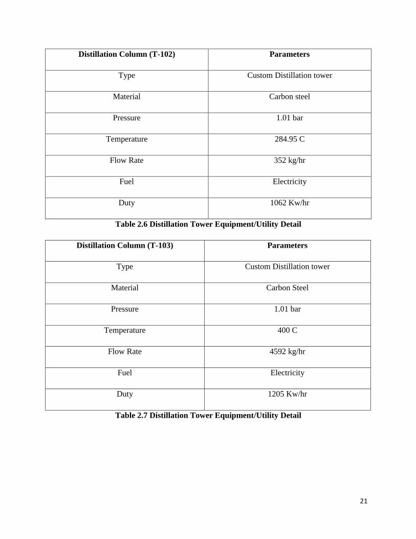
Distillation Column (T-102) Parameters
Type Custom Distillation tower
Material Carbon steel
Pressure 1.01 bar
Temperature 284.95 C
Flow Rate 352 kg/hr
Fuel Electricity
Duty 1062 Kw/hr
Table 2.6 Distillation Tower Equipment/Utility Detail
Distillation Column (T-103) Parameters
Type Custom Distillation tower
Material Carbon Steel
Pressure 1.01 bar
Temperature 400 C
Flow Rate 4592 kg/hr
Fuel Electricity
Duty 1205 Kw/hr
Table 2.7 Distillation Tower Equipment/Utility Detail
22
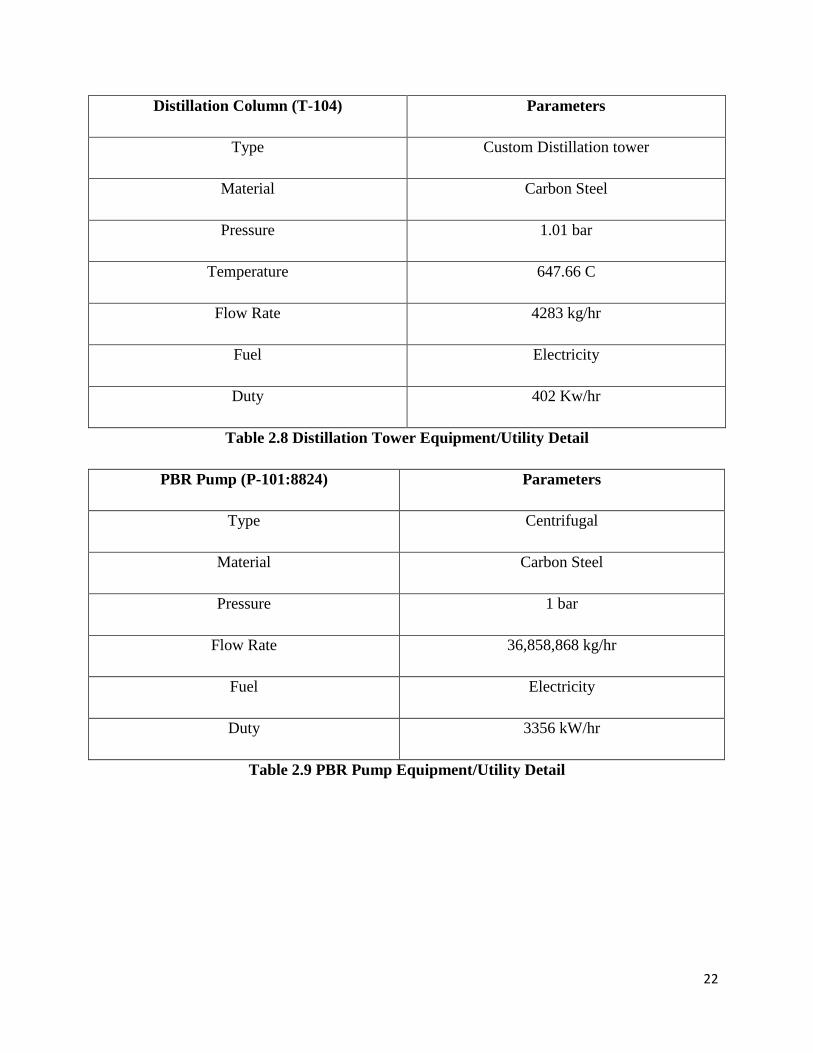
Distillation Column (T-104) Parameters
Type Custom Distillation tower
Material Carbon Steel
Pressure 1.01 bar
Temperature 647.66 C
Flow Rate 4283 kg/hr
Fuel Electricity
Duty 402 Kw/hr
Table 2.8 Distillation Tower Equipment/Utility Detail
PBR Pump (P-101:8824) Parameters
Type Centrifugal
Material Carbon Steel
Pressure 1 bar
Flow Rate 36,858,868 kg/hr
Fuel Electricity
Duty 3356 kW/hr
Table 2.9 PBR Pump Equipment/Utility Detail
23
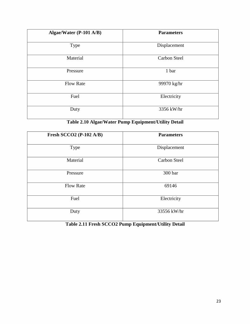
Algae/Water (P-101 A/B) Parameters
Type Displacement
Material Carbon Steel
Pressure 1 bar
Flow Rate 99970 kg/hr
Fuel Electricity
Duty 3356 kW/hr
Table 2.10 Algae/Water Pump Equipment/Utility Detail
Fresh SCCO2 (P-102 A/B) Parameters
Type Displacement
Material Carbon Steel
Pressure 300 bar
Flow Rate 69146
Fuel Electricity
Duty 33556 kW/hr
Table 2.11 Fresh SCCO2 Pump Equipment/Utility Detail
24
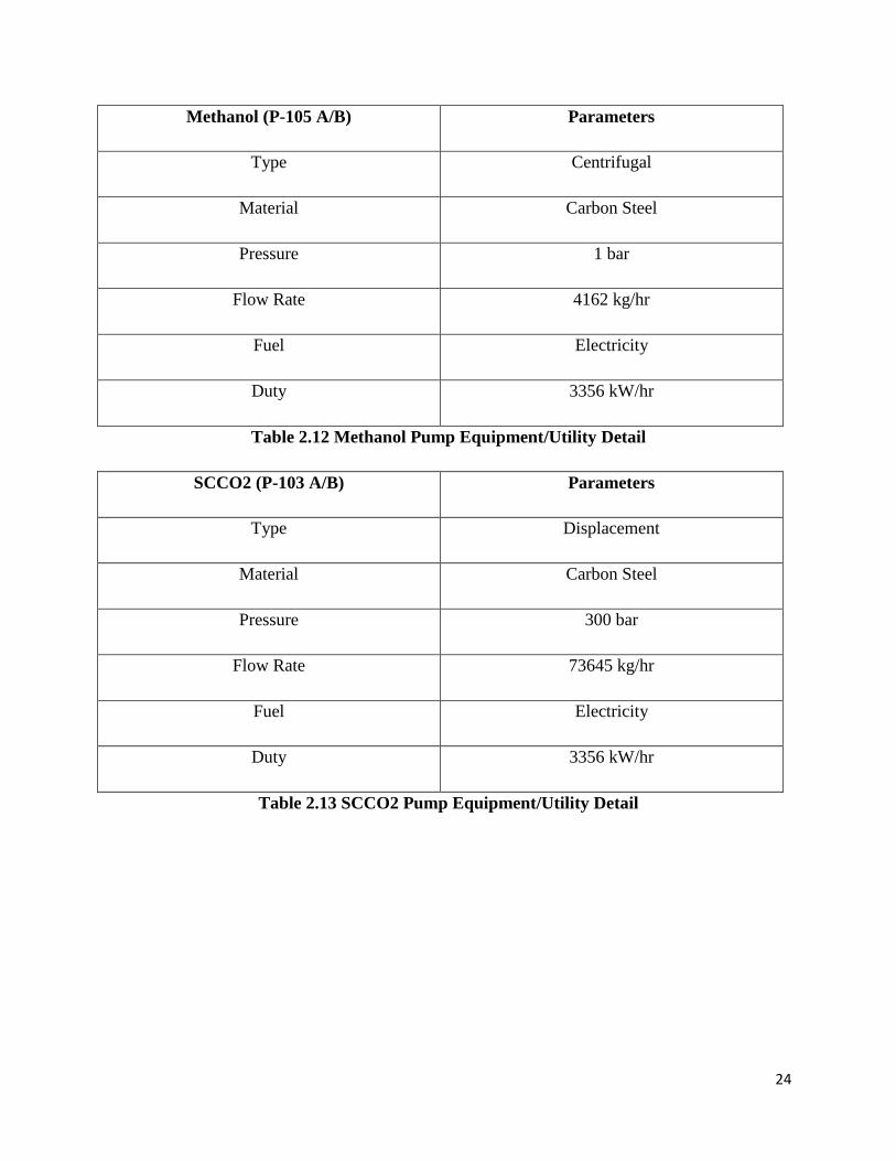
Methanol (P-105 A/B) Parameters
Type Centrifugal
Material Carbon Steel
Pressure 1 bar
Flow Rate 4162 kg/hr
Fuel Electricity
Duty 3356 kW/hr
Table 2.12 Methanol Pump Equipment/Utility Detail
SCCO2 (P-103 A/B) Parameters
Type Displacement
Material Carbon Steel
Pressure 300 bar
Flow Rate 73645 kg/hr
Fuel Electricity
Duty 3356 kW/hr
Table 2.13 SCCO2 Pump Equipment/Utility Detail
25
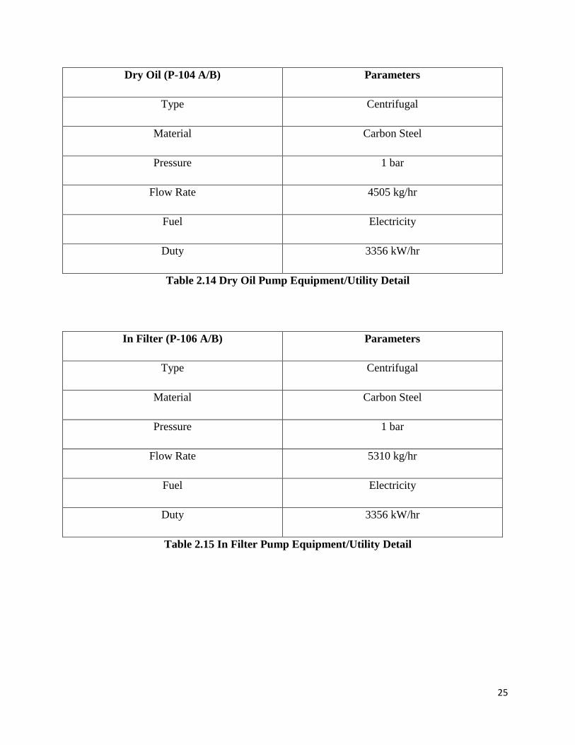
Dry Oil (P-104 A/B) Parameters
Type Centrifugal
Material Carbon Steel
Pressure 1 bar
Flow Rate 4505 kg/hr
Fuel Electricity
Duty 3356 kW/hr
Table 2.14 Dry Oil Pump Equipment/Utility Detail
In Filter (P-106 A/B) Parameters
Type Centrifugal
Material Carbon Steel
Pressure 1 bar
Flow Rate 5310 kg/hr
Fuel Electricity
Duty 3356 kW/hr
Table 2.15 In Filter Pump Equipment/Utility Detail
26
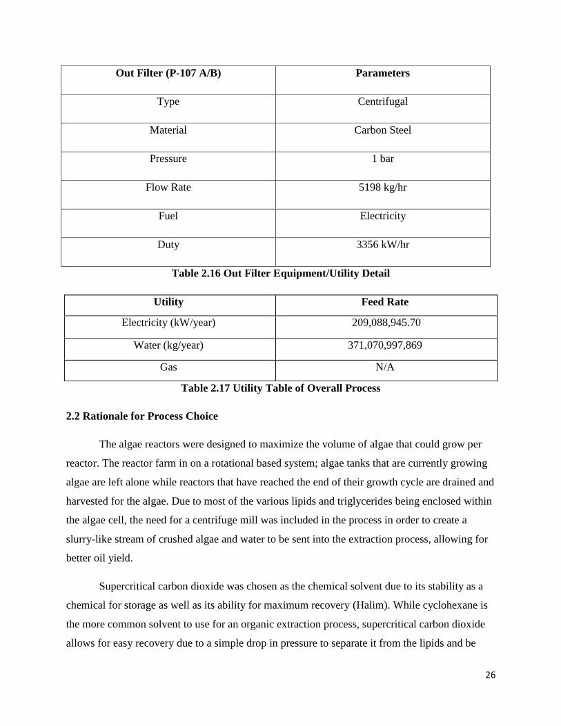
Out Filter (P-107 A/B) Parameters
Type Centrifugal
Material Carbon Steel
Pressure 1 bar
Flow Rate 5198 kg/hr
Fuel Electricity
Duty 3356 kW/hr
Table 2.16 Out Filter Equipment/Utility Detail
Utility Feed Rate
Electricity (kW/year) 209,088,945.70
Water (kg/year) 371,070,997,869
Gas N/A
Table 2.17 Utility Table of Overall Process
2.2 Rationale for Process Choice
The algae reactors were designed to maximize the volume of algae that could grow per
reactor. The reactor farm in on a rotational based system; algae tanks that are currently growing
algae are left alone while reactors that have reached the end of their growth cycle are drained and
harvested for the algae. Due to most of the various lipids and triglycerides being enclosed within
the algae cell, the need for a centrifuge mill was included in the process in order to create a
slurry-like stream of crushed algae and water to be sent into the extraction process, allowing for
better oil yield.
Supercritical carbon dioxide was chosen as the chemical solvent due to its stability as a
chemical for storage as well as its ability for maximum recovery (Halim). While cyclohexane is
the more common solvent to use for an organic extraction process, supercritical carbon dioxide
allows for easy recovery due to a simple drop in pressure to separate it from the lipids and be
27
easily compressed back to a supercritical state. Additionally, almost 100% of the fluid can be
recycled (Appendix E.2). Because of these reasons, it is also a more environmentally-friendly
option, a goal of the plant design which is discussed further in Section 4.
A transesterification reaction was chosen as the heart of the process for several reasons.
First, due to the relatively low temperatures and atmospheric pressure conditions of the reaction,
costs and safety hazards can be more avoided compared to a more intensive reaction. Second, the
main reagent, methanol, is a relatively cheap reactant and can be recycled and reused further
down the process as a solvent in the liquid-liquid extractor. Third, because glycerol is the only
side product and is a heavy polar compound, the separation of the methyl ester product is easier
and also has a market value to be sold for additional revenue. The kinetics of the reaction also
work in favor of the design, capping out a relatively high conversion of 0.8 of methyl esters for a
base-catalyzed reaction (Appendix E.3). The catalyst used, potassium carbonate, is cheap, safe
and stable, making it an ideal catalyst for use in the reaction (Schuchardt).
The liquid-liquid extraction process was employed to separate unreacted triglycerides,
glycerol, methanol and methyl esters, as well as undesired lipids into two streams (Section 3.5).
The solvent of choice was methanol, not only due to its ability to adsorb the chemicals into a
stream effectively, but also due to it being used upstream as a reagent, further reducing the cost
of feedstock chemical as one chemical can be used for two different processes (Appendix E.4).
The final distillation columns were designed in such a way to separate the methanol,
methyl esters, unreacted components, waste, and glycerol. The choice of design was a flash
distillation for the methanol stream coming out of the LLE, then fed into another multistage
distillation column. The exiting streams are fed into multistage distillation columns, which create
a stream of high purity product of methyl esters and glycerol, a stream of methanol that is then
fed back into the methanol storage, and a stream of waste that can be disposed of (Section 3.6).
Various centrifugal and displacement pumps were selected to keep flow rates and
pressures are their desired parameters. Centrifugal pumps were assigned to streams in which only
liquid is present. Avoidance of gaseous species is necessary for centrifugal pumps to avoid
cavitation. Displacement pumps were then used for gas/liquid streams along with high pressure

28
streams to maintain constant flow. Table 2.9 to Table 2.16 present the parameters and pump
types for each pump. Calculations can be seen in Appendix E6.
29
Process and Equipment Rationale and Optimization
3.1 R101:8824 Algae Reactor
The algae used in the reactor is composed of three strains of freshwater algae; Chorella
Vugaris, Chlorella Sorokiniana, and Scenedesmus (Mentor Meeting Minutes, February 3, 2016).
These algae were chosen due to the synergistic nature of the three strains growing in proximity to
one another. They provide a more robust and complete nutrition source for animal feedstock
after the conversion of algae to lipid feedstock. This could enable a higher-value commodity for
the algae production plant, in addition to the fabrication of biodiesel.
A single algae reactor is composed of an acrylic cylindrical column, three meters tall with
a diameter of half a meter. The rationale for the dimension of the reactor is, primarily, due to the
need for algae to have access to light penetration within the reactor in order to grow and the
logistics of obtaining the acrylic columns (Hochhalter).
Light and temperature are undoubtedly the major limiting factor in high density algal
cultures (Lee). Algae grow best around 30 ºC. The properties of light energy most important for
algae growth and metabolism in our plant setting is intensity. Algae survive and grow best in
intensity ranges of 2,000-5,000 foot-candles. Extra sunny days can have up to 12,000 foot-
candles (Small). Therefore, a lux meter that monitors the flux of light emittance per unit area is
kept on site, and weather is monitored on a daily basis by employees. A shade cloth is to be
purchased and used to shade the reactors from ambient light that is determined to be too intense
(greater than 5,000 foot-candles).
Following the explanation of a single reactor at standard temperature and pressure for the
algae, the rationale for the number of reactors is discussed. In order to accommodate the
production goal of 831 barrels of biodiesel made per day, a total of nearly 8,507 cubic meters of
photobioreactor space is needed, which translates into 8,592 individual column reactors. This
number was increased to 8,824 based off of a three percent excess due to the potential for reactor
repairs. The amount of algae needed is based on the average growth rate of our three strains. This
was then used to calculate the amount of space needed to grow the algae over a two-week period.
Each individual photobioreactor is part of a series of units that are operated in unison to drain
into the continuous process every two weeks when the algae within has matured. All calculations

30
are seen in Appendix E.1. From the algae reactors the stream is sent to an extractor down the
line.
3.2 T-101 Supercritical carbon dioxide solid-liquid extractor
A supercritical carbon dioxide extractor was chosen due to its environmental
sustainability, operating cost, and extraction abilities. While other solvents exist (like
cyclohexane), in order to extract the organic stream supercritical carbon dioxide is a much safer
chemical in terms of health hazards to both human life as well as environmental concerns.
Because supercritical carbon dioxide is nonpolar, it easily dissolved the nonpolar lipids. Due to
the ability to easily change the state of carbon dioxide, almost all of the carbon dioxide can be
recovered and reused in the extraction process with very little process design (Appendix E.2). A
liquid chemical like cyclohexane would pose more difficult in its separation from the desired
product, requiring distillation or additional process design and cost. As a solvent, carbon dioxide
also has a much higher recovery rate in the organic stream than cyclohexane. Cyclohexane caps
out at approximately 90% recovery while supercritical carbon dioxide can reach up to 98-100%
recovery (Oblad). The parameters for the extractor were 60 °C and 300 bar to ensure
supercritical levels ( McCabe 790). The flow rates into and out of the extractor were calculated,
with a total of 169,116 kg/hr flowing in and out. A lipid to algae ratio of 0.27 was used (El
Maghraby). The barrels produced per day from the extractor was determined to be 1017 which
meets market needs of 831 barrels per day. Additionally, the volume of the extractor was found
to be approximately 47 m3 (Appendix E.2). A unit sold through Eden Labs consists of an
extractor, separator, compressor, and heat exchanger at 6000 liters per unit. 8 units are to be
purchased using an Alibaba cost reference (Alibaba, "Supercritical Co2 Extraction
Machine/Equipment/Extractor").
The incoming stream is set at 60 ºC at 300 bar and contains 73,645 kg/hour, which flows
directly from the supercritical carbon dioxide extractor. Because ChemCad, or any chemical
simulation program, does not contain the exact lipid mixture under study, arachidic acid was
selected to substitute the experimental lipids. This particular lipid was chosen because it has a
similar chain length of 20 carbons and a relatively similar molecular weight of 304.5 g/mol
compared to the 393.5 g/mol average of the actual lipid mixture. Because supercritical carbon
31
dioxide has almost 100% separation at the appropriate pressure, it was decided that a lipid
substitution in ChemCad was a proper analysis of the lipid separator process (Facilitator Meeting
Minutes, March 9, 2016). Once it enters the valve, the pressure is dropped to 50 bar. This
parameter was chosen to achieve complete separation while also reducing the cost. When
analyzing a supercritical carbon dioxide phase diagram, at 60 ºC, a pressure drop from 300 bar to
50 bar results in a phase change from supercritical to gas (Appendix E.2). There is no need to
drop the pressure down to 1 bar; therefore, the smaller pressure drop allows for less energy input,
ultimately reducing the cost. The simulation was run to achieve 69,140 kg/hr, which is almost
100% percent separation.
3.3 R-101/102 Transesterification CSTRs
The plant design was based around a transesterification reaction due to many reasons.
The kinetics behind the transesterification excel at processes done at standard temperatures and
pressures, making it ideal for a large scale up for an industrial application. Standard temperatures
mean the reactors do not require additional heating, reducing energy costs. The first reactor was
sized to be 6,200 L, while the second reactor was sized to 7,400 L. The size of each reactor not
only accounts for volume required to reach desired conversion but for enough space for both the
mixer and additional room in case of overfilling. A mixer was fitted to each reactor with a 1 m
diameter impeller blade that will have a speed of 0.19 rotations per second. The mixer serves to
speed up the rate limiting step of the reaction, mass transfer, in order to decrease the required
residence time. The speed of the mixer was chosen as reference to literature which based the
order of the reaction off of a Reynolds number of 12,400. In terms of the reaction, the kinetics
allow for a maximum conversion of approximately 0.8, allowing for a high yield per reactant
(Appendix E.3). The chemistry requires only one additional reactant in the form of methanol.
Methanol is very advantageous for the process due to being a relatively low cost reagent, easy to
store, and safe. Methanol can be safely stored on site in a tank without any consideration to
storage design or safety besides low level hazard operations. The catalyst for the reaction,
potassium carbonate, was chosen due to its ability to lower the activation energy enough to
create a favorable reaction to methyl esters.
32
The reaction was chosen to be base-catalyzed rather than acid-catalyzed due to an overall
increase in conversion. Potassium carbonate, a solid, was chosen over liquid-based catalysts such
as potassium hydroxide in order to prevent the saponification of the methyl ester product into a
water and salt (Julkowski and DuPont). The saponification process would not only be very
difficult to design for and prevent in an industrial setting, but it would require further distillation
and separation of created water and soap products, as well as neutralization of any remaining
sodium hydroxide or another separation process to remove it. With the solid catalyst choice, a
simple filtration can be done after exiting the reactor in order to remove all of the catalyst. While
this will require changing of filtration and a manual recycle, the reduced design costs will
compensate. The reaction is also advantageous due to the formation of the side product, glycerol.
While not used as a biofuel, glycerol has a place as a commodity in the market, allowing for the
side product to be easily refined through a distillation and sold as well, increasing profit for the
plant. The design choice for two CSTRs in series was due to the maximization of conversion
while minimizing the amount of volume or residence time in the CSTR. Two CSTRs in series
reduce the volume needed to reach the desired conversion of 0.8, allowing for more time and
space to be saved in plant design.
3.4 E-101 Catalyst Filtration
Due to the presence of a solid catalyst in the reaction process, the catalyst must be filtered
out before moving on through the process cycle. The potassium carbonate can be recycled and
reused once recovered. In order to do so, a catalyst filtration system was imposed that pumps the
reaction mixture through a filtration system that removes and recovers the solid product. Due to
the pressure loss through the filtration, a secondary pump is employed on the other side to
increase the flow rate back to nominal (Section 2, Figure 2.16).
The equipment being used for the operation is a 0.1-micron porous ceramic disk filter
with an area of 24m2. The size of the filter will remove the catalyst from the flow stream as well
as any other potential solid algae particulate that made it through the process. The filter operates
off of a vacuum principle in order to pull the outgoing flow rate of the CSTR through the filter
and then pass through the machine into the LLE. Due to the design of the filtration system. The
filter will have to be manually removed and catalyst will have to be collected and replaced after
33
the filter becomes full of catalyst. Until operational processes begin, it is unable to be determined
the rate at which the filters will require changing or rate of wear on the filters themselves. The
machine is operated for a use life of more than 10 years and with 0.5 kW/ton power draw due to
the filtration action coming from the pressure difference of the pumps before and after the
machine (Appendix E.3).
3.5 V-102 Liquid-Liquid Extractor
The liquid-liquid extractor (LLE) is based on design specifications from Oak Ridge
National Laboratories and the Shell Corporation (Pike and Royal Dutch Shell Group). The LLE
uses the principle of solvent partitioning and extraction to separate compounds, based upon
solubility, into two immiscible liquids. Liquid-liquid extraction takes the feed solution
(unreacted triglycerides and fatty acid methyl esters) and a solvent stream (methanol) and allows
the transfer of the high-value extract from the feed solution that is depleted in solute. This
depleted solute is called the raffinate, and in our case will contain methanol and glycerol. The
LLE chosen was a model rotating disk due to the abundant amount of literature available on this
model. A column (versus horizontal) LLE reactor was chosen due to the minimal height and
diameter (~26 and 15 ft, respectively) that yields a volume of 2,039 cubic feet (Appendix E.4).
Methanol was chosen as the solvent because of its presence in the feed solution and because of
the miscibility of glycerol in methanol and immiscibility of the extracts in methanol (unreacted
triglycerides and our fatty acid methyl esters). The presence of methanol in the feed solution,
combined with its use as a solvent, allows for the process to use fewer overall separation unit
operations; thereby saving both operating and capital costs.
3.6 T-102 Flash / T-103 and T-104 Stage Distillation Tower(s)
The feeds from the LLE consists of two streams: one that contains the raffinate and the
other which contains the extract and solutes. The stage and flash distillation processes are
composed of a total of three distillation towers. Two distillation towers are used to purify the
extract and solutes stream; the first tower (T-103) is used to separate the remaining methanol,
which is sent to the second tower (T-102) that processes the raffinate stream (the methanol and
glycerol) from the remaining methyl ester and triglycerides. The third tower (T-104) in the stage
process is used to separate the methyl ester and triglycerides, and to get a purity of biodiesel (the

34
methyl esters) of 99.973%. The third tower (T-104) is used to separate the methanol, to be
recycled back into the process, from the glycerol. In order to get the purity needed at each step of
the overall separation process, the number of trays needed varied according to the components of
each step. The tower (T-102) that separates the initial raffinate stream and the distillate from the
second tower (T-103) in the extract stream needs 3 trays to separate the methanol from the
glycerol in order to get a 99.9997% separation of methanol from glycerol. The first tower (T-
103) from the extract stream needed 4 trays to obtain a 99.89% capture of methanol in the
distillate. The last tower (T-104) needs 8 trays to separate the methyl esters form the triglycerides
in order to obtain the purification of biodiesel (99.97%) for the process (Appendix E.5).
35
Section 4: Safety and Environmental Factors
4.1 General Plant Considerations
Biodiesel itself is nonflammable and biodegradable while some of the chemicals involved
in the synthesis of this product pose slightly more threat. While algae and carbon dioxide are
friendly to workers and the environment, the use of methanol and potassium carbonate catalyst
are to be handled with care as they are both toxins and irritants when in contact with.
Additionally, the overall process involves extremely high pressures in which valves, pumps, and
pieces of equipment are to be monitored regularly. Workers are to follow all protocol and safety
measurements for maximum safety (Appendix H).
4.2 Personal Protection Equipment
Personal protective equipment is standard with the exception of that of the workers
handling the potassium carbonate catalyst and methanol. Workers are required to wear NOSH
respirators with N95 cartridges to protect from dry catalyst inhalation, as potassium carbonate
causes respiratory distress. Additionally, the catalyst, when mixed with methanol, can generate a
dust that is toxic when inhaled (Potassium Carbonate MSDS).
4.3 Major Equipment Hazard Operation
Algae Photobioreactor (R-101:8824)
While none of the chemicals flowing through the algae photobioreactor are hazardous,
several nodes of the equipment can be altered that would then influence the operation,
economics, and safety of the equipment and workers. Because the bioreactor relies on pumps and
valves to control flow, daily safety inspections are to be performed on the piping, pumps, and
valves. Though the process operates at standard pressure and temperatures to allow for algae
growth, errors in pressure gauges and pumps or leaks in pipes can influence the flow rate,
36
pressure, speed, composition, and time allowed for reactions and growth to occur. While high or
low concentrations of nutrient, air, and water do not have environmental or hazardous
consequences, too high of CO2 concentrations can pose a risk to workers and the air quality
around the plant. Signs are posted around the equipment, and equipment is checked daily and
signed by workers (Appendix H.1).
Supercritical CO2 Extraction (T-101)
Operation of the supercritical CO2 extraction poses several hazards. The primary of this
being the fact that this process runs at an elevated pressure of 300 bar. A system at this pressure
can be dangerous in the event of a catastrophic equipment failure that leads to an explosive
decompression. If a failure such as this were to occur during plant operation, it could lead to
serious injury or death of those nearby as well as severe damage to nearby equipment. For this
reason, the pressure inside the extraction vessel and piping should be continuously monitored. If
pressure levels rise above normal operation, this pressure should be released as quickly as
possible through a release valve. The system should be routinely checked for leaks and
equipment integrity to avoid sudden losses of pressure or equipment failure. The system needs to
be monitored for leaks and temperature control as well (Appendix H.2)
CSTR (R-101/102)
CSTR operation requires no extra attention due to the stable nature of the reaction taking
place. The CSTR reactor operates at a temperature of 60 ºC in an open-to-atmosphere reactor, so
pressure or temperature hazards are not present. Both CSTR reactors have low speed, propeller
blade mixers operating in them at all times. It is important that operators both maintain and
monitor the speed of the blades at all time to prevent motor burnout or arbitrary increase in RPM.
Entering the reactor is a stream of methanol and triglycerides, as well as an addition of potassium
carbonate as a catalyst, chemicals of which incur a hazard (See Section 4.4 for MSDS); however,
should process failure occur upstream, proper direction should be taken with monitoring liquid
levels in the tanks at all times so that they do not overflow. During potential repairs/cleanout
operations, a proper lockout/tagout procedure must be followed for the CSTR reactors. Each
reactor is a confined space that needs to have proper OSHA procedure followed, as well as the
37
addition of the mixer blades inside, requiring proper safety equipment and procedure to prevent
mechanical injury or death (Appendix H.3).
Distillation Towers (T-101/102/103)
When analyzing the distillation towers, the feeds need to be taken into consideration.
Temperature and pressure sensors are installed that are monitored daily and signed off by
employees. This is to ensure no pipe bursts occur and that towers are operating efficiently. The
tower vessel contains an alarm, pressure sensor, and relief valve to ensure efficient separation of
products. Similarly, the pipes leaving the reboiler and the condenser will be monitored for
temperature and composition by utilizing flow meters, temperature controllers, and pressure
sensors (Appendix H.4).
4.4 Chemical Storage Hazards
Methanol is considered the most dangerous chemical used in the synthesis of biodiesel. It
is a colorless liquid that burns clear making it invisible during the day and a hazard to those
around. Additionally, methanol decomposes at high temperatures to carbon monoxide, which is
highly toxic. It is a skin and eye irritant and, when inhaled, causes nausea, headaches,
incoordination, possible blindness, or even death. Additionally, it can cause birth defects if
exposed to pregnant women ("Occupational Health Guideline for Methyl Alcohol"). Because of
its toxicity and flammability, extreme safety precautions are taken in the handling and storage of
methanol. "No smoking" and "No open flames" signs are present throughout the entire storage
and process facility. All electrical equipment is explosion proof and covered with insulated
material near the handling of methanol. When stored, the methanol is held in cool, dry
environments above ground away from oxidizers, acids, and metals. NFPA 70E standard and
NFPA 497 are used to evaluate storage procedures. All proper fire extinguishers, spill kits, and
signs are present in the storage area (Methanol MSDS).
Potassium carbonate is toxic when inhaled and ingested and is an irritant to the skin and
eyes. Ingestion can lead to stomach and intestinal irritation, burns, shock, and even death.
Potassium carbonate is more prone to inhalation in its dust form. Therefore, no eating, drinking,
or smoking is allowed near the handling of the catalyst. The catalyst is kept in non-used, air-
38
tight, labeled containers in a cool, dry location separate from the following chemicals/substances:
acids, lime, metals, and alloys. Additionally, when mixed with alcohols, a variety of mists can be
generated. Therefore, separation from methanol storage is essential (Potassium Carbonate
MSDS).
Carbon dioxide, when at concentrations greater than 10% can cause unconsciousness or
death because it is an asphyxiant. Liquid or cold vapor contact to the eyes or skin can lead to
tissue damage. Inhalation can lead to asphyxiation, shortness of breath, dizziness, or visual
disturbance. Carbon dioxide is to be stored at temperatures below 52 °C away from corrosive
materials. Storage and handling should meet requirements of Compressed Gas Association, Inc.
(Carbon Dioxide MSDS).
Though air poses no immediate threats when in contact, compressed air from a
pressurized tank can cause frostbite or tissue death upon skin, eyes, or lungs (when inhaled) due
to the Joule-Thompson Effect. Compressed air in cylinders is under pressure and should be
stored at temperatures below 52 °C and away from sunlight to prevent explosions (Air MSDS).
4.5 Environmental Impact Assessment
The plant design, as well as final product, revolves around the idea of a smaller
environmental footprint. The final product of methyl esters is a stable chemical composition that
is both safe and environmentally friendly with regards to human life. In regards to the Casa
Grande City Code, Chapter 17.58 specifies environmental handling regulations, including no
chemical disposal onsite along with specifications on bulk storage that comply with Uniform
Building and Fire Code ("Buildings and Construction"). No nearby lakes, ponds, or wildlife
reserves in the immediate area are present near Casa Grande, Arizona. The plant location is also
isolated from residential human life, so any potential run offs do not pose an immediate threat.
Methanol spills require standard clean up procedures, and, barring a large spill of the
main storage, methanol is safe for the environment. Additionally, methanol was used as a
chemical utility in both the transesterification process and the liquid extraction process. Through
the final distillation, almost all of the methanol is recovered and able to be reused in the process
continuously.
39
The algae extractor was designed around renewability and environmental friendliness.
Cyclohexane is normally a popular solvent for the extraction process; however it comes with
major environmental and human health concerns in terms of its operation. Using supercritical
CO2, the process is not only able to recover 99-100% of the CO2 used for extraction in recycle,
but its inertness and stability allows for safe human operation. Naturally, CO2 itself is a
greenhouse gas that is environmentally destructive; however, with the near perfect recycle, little
to none of the CO2 used in operation escapes the process into the atmosphere.
Due to the number of pumps and pieces of equipment utilized, the electricity and water
cost of the plant is immense. 209,088,945 kW per year along with 3,710,709,978 gallons of
water per year amounts to a large cost and environmental footprint (Excel, 'Feedstocks and
Utilities'). It is estimated that 1,100 g CO2 are produced for every kW/hr meaning the utilities for
the plant alone produce twice the amount of CO2 that the algae is able to sequester (Turney).
Future development on electricity-efficient pieces of equipment will help lower this number.
Because of the amount of electricity and CO2 generated, global warming is the category
impacted the most in regards to the life cycle assessment. However, overall, the impact is far
lower than that of a traditional fuel refinery plant.
40
Section 5: Economic Analysis Including Economic Hazards
The chemical feedstocks for the process were priced using Chemical Industry Market.
Due to the large amount of chemical quantities needed, they are considered purchased as
utility feedstock fed to the plant. Nitrogen, Phosphorus, and Potassium (NPK) fed into the algae
tank as nutrients were priced at $400/ ton. The amount of NPK needed for the incubation of the
algae is 100 grams per liter of water. The methanol feed is the most expensive purchased
chemical for the plant start up. Methanol was priced at $350/ton and, due to the large quantities
that will be purchased, it will be stored in a holding tank on site with a surplus amount in case of
supply chain issues. NPK comes in at the second largest cost and quantity for feed
stock. Potassium carbonate, the catalyst for the reaction, is the third largest purchasing chemical,
however due to its nature as a catalyst, it should have near 100% recovery in the process.
Nevertheless, additional catalyst was factored into economics due to the realistic, less than
perfect recovery rate. The last chemical needed as feed for the plant, carbon dioxide, comes in as
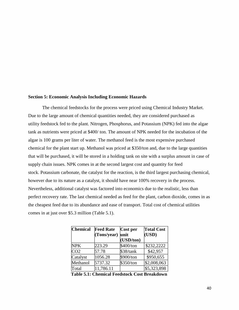
the cheapest feed due to its abundance and ease of transport. Total cost of chemical utilities
comes in at just over $5.3 million (Table 5.1).
Chemical Feed Rate
(Tons/year) Cost per
unit
(USD/ton)
Total Cost
(USD)
NPK 223.29 $400/ton $232,2222
CO2 57.78 $38/tank $42,957
Catalyst 1056.28 $900/ton $950,655
Methanol 5737.32 $350/ton $2,008,063
Total 11,786.11 $5,323,898
Table 5.1: Chemical Feedstock Cost Breakdown
41
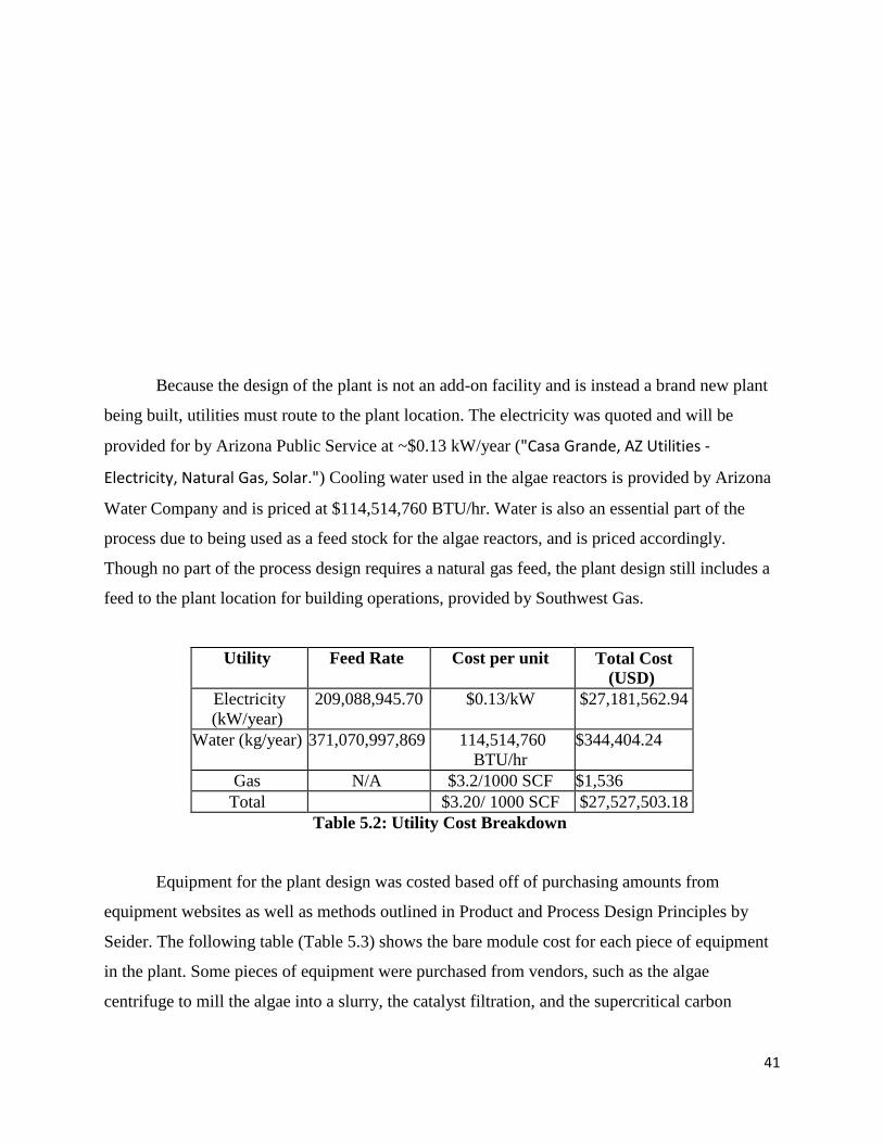
Because the design of the plant is not an add-on facility and is instead a brand new plant
being built, utilities must route to the plant location. The electricity was quoted and will be
provided for by Arizona Public Service at ~$0.13 kW/year ("Casa Grande, AZ Utilities -
Electricity, Natural Gas, Solar.") Cooling water used in the algae reactors is provided by Arizona
Water Company and is priced at $114,514,760 BTU/hr. Water is also an essential part of the
process due to being used as a feed stock for the algae reactors, and is priced accordingly.
Though no part of the process design requires a natural gas feed, the plant design still includes a
feed to the plant location for building operations, provided by Southwest Gas.
Utility Feed Rate Cost per unit Total Cost
(USD)
Electricity
(kW/year)
209,088,945.70 $0.13/kW $27,181,562.94
Water (kg/year) 371,070,997,869 114,514,760
BTU/hr
$344,404.24
Gas N/A $3.2/1000 SCF $1,536
Total $3.20/ 1000 SCF $27,527,503.18
Table 5.2: Utility Cost Breakdown
Equipment for the plant design was costed based off of purchasing amounts from
equipment websites as well as methods outlined in Product and Process Design Principles by
Seider. The following table (Table 5.3) shows the bare module cost for each piece of equipment
in the plant. Some pieces of equipment were purchased from vendors, such as the algae
centrifuge to mill the algae into a slurry, the catalyst filtration, and the supercritical carbon
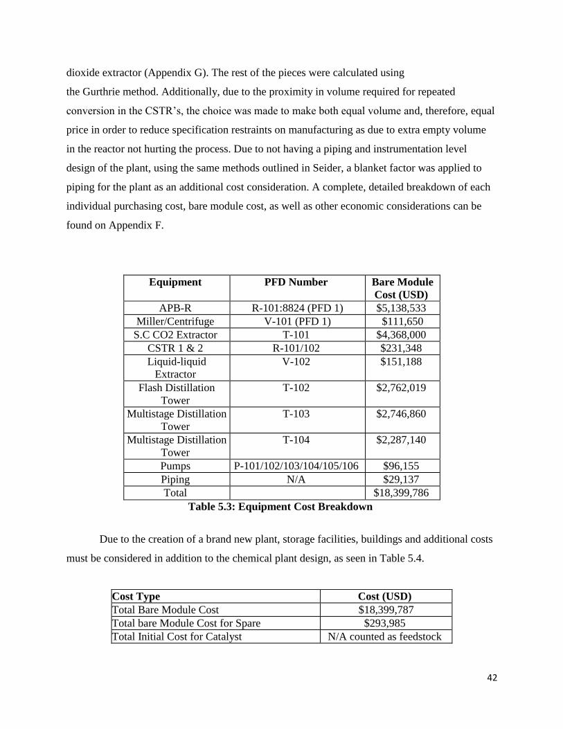
42
dioxide extractor (Appendix G). The rest of the pieces were calculated using
the Gurthrie method. Additionally, due to the proximity in volume required for repeated
conversion in the CSTR’s, the choice was made to make both equal volume and, therefore, equal
price in order to reduce specification restraints on manufacturing as due to extra empty volume
in the reactor not hurting the process. Due to not having a piping and instrumentation level
design of the plant, using the same methods outlined in Seider, a blanket factor was applied to
piping for the plant as an additional cost consideration. A complete, detailed breakdown of each
individual purchasing cost, bare module cost, as well as other economic considerations can be
found on Appendix F.
Equipment PFD Number Bare Module
Cost (USD)
APB-R R-101:8824 (PFD 1) $5,138,533
Miller/Centrifuge V-101 (PFD 1) $111,650
S.C CO2 Extractor T-101 $4,368,000
CSTR 1 & 2 R-101/102 $231,348
Liquid-liquid
Extractor
V-102 $151,188
Flash Distillation
Tower
T-102 $2,762,019
Multistage Distillation
Tower
T-103 $2,746,860
Multistage Distillation
Tower
T-104 $2,287,140
Pumps P-101/102/103/104/105/106 $96,155
Piping N/A $29,137
Total $18,399,786
Table 5.3: Equipment Cost Breakdown
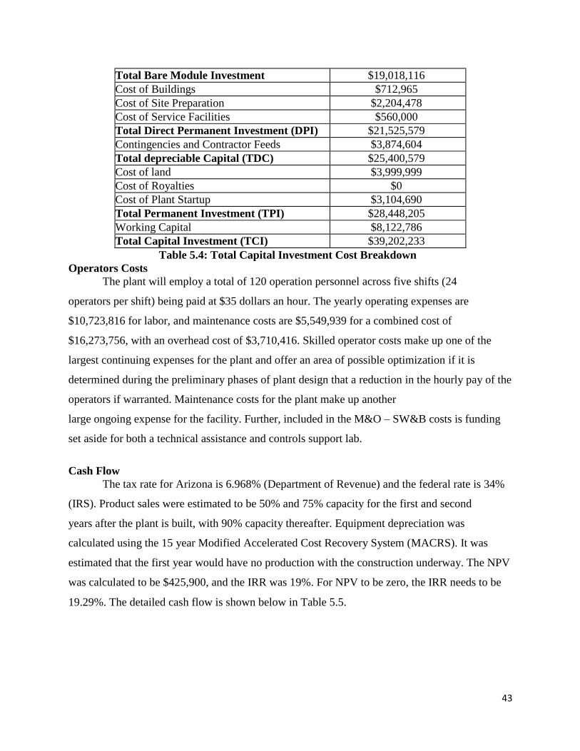
Due to the creation of a brand new plant, storage facilities, buildings and additional costs
must be considered in addition to the chemical plant design, as seen in Table 5.4.
Cost Type Cost (USD)
Total Bare Module Cost $18,399,787
Total bare Module Cost for Spare $293,985
Total Initial Cost for Catalyst N/A counted as feedstock
43
Total Bare Module Investment $19,018,116
Cost of Buildings $712,965
Cost of Site Preparation $2,204,478
Cost of Service Facilities $560,000
Total Direct Permanent Investment (DPI) $21,525,579
Contingencies and Contractor Feeds $3,874,604
Total depreciable Capital (TDC) $25,400,579
Cost of land $3,999,999
Cost of Royalties $0
Cost of Plant Startup $3,104,690
Total Permanent Investment (TPI) $28,448,205
Working Capital $8,122,786
Total Capital Investment (TCI) $39,202,233
Table 5.4: Total Capital Investment Cost Breakdown
Operators Costs
The plant will employ a total of 120 operation personnel across five shifts (24
operators per shift) being paid at $35 dollars an hour. The yearly operating expenses are
$10,723,816 for labor, and maintenance costs are $5,549,939 for a combined cost of
$16,273,756, with an overhead cost of $3,710,416. Skilled operator costs make up one of the
largest continuing expenses for the plant and offer an area of possible optimization if it is
determined during the preliminary phases of plant design that a reduction in the hourly pay of the
operators if warranted. Maintenance costs for the plant make up another
large ongoing expense for the facility. Further, included in the M&O – SW&B costs is funding
set aside for both a technical assistance and controls support lab.
Cash Flow
The tax rate for Arizona is 6.968% (Department of Revenue) and the federal rate is 34%
(IRS). Product sales were estimated to be 50% and 75% capacity for the first and second
years after the plant is built, with 90% capacity thereafter. Equipment depreciation was
calculated using the 15 year Modified Accelerated Cost Recovery System (MACRS). It was
estimated that the first year would have no production with the construction underway. The NPV
was calculated to be $425,900, and the IRR was 19%. For NPV to be zero, the IRR needs to be
19.29%. The detailed cash flow is shown below in Table 5.5.
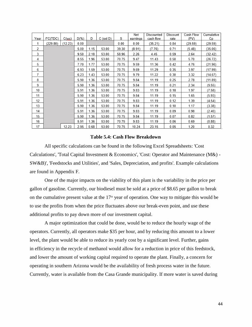
44
Table 5.4: Cash Flow Breakdown
All specific calculations can be found in the following Excel Spreadsheets: 'Cost
Calculations', 'Total Capital Investment & Economics', 'Cost: Operator and Maintenance (M&) -
SW&B)', 'Feedstocks and Utilities', and 'Sales, Depreciation, and profits'. Example calculations
are found in Appendix F.
One of the major impacts on the viability of this plant is the variability in the price per
gallon of gasoline. Currently, our biodiesel must be sold at a price of $8.65 per gallon to break
on the cumulative present value at the 17th year of operation. One way to mitigate this would be
to use the profits from when the price fluctuates above our break-even point, and use these
additional profits to pay down more of our investment capital.
A major optimization that could be done, would be to reduce the hourly wage of the
operators. Currently, all operators make $35 per hour, and by reducing this amount to a lower
level, the plant would be able to reduce its yearly cost by a significant level. Further, gains
in efficiency in the recycle of methanol would allow for a reduction in price of this feedstock,
and lower the amount of working capital required to operate the plant. Finally, a concern for
operating in southern Arizona would be the availability of fresh process water in the future.
Currently, water is available from the Casa Grande municipality. If more water is saved during
45
operation, then that could reduce the strain that our plant would place on industries and residence
in Arizona, and help to reduce the operating cost.
Section 6: Conclusion and Recommendations
The plant design as a whole is based off of bench scale research, resulting in many
idealized conditions that may not translate well, if at all, to a large scale industrial practice.
However, without any precedent of algae based bio refineries, knowledge of design had to
be synthesized from chemical engineering theory and scientific literature. The design of the algae
bioreactors themselves, due to the ceramic material and sheer amount of reactors needed, might
prove to be unmanageable. Without experimenting with small scale design, only idealized
growth rates and optimal conditions can be predicted. Should weather patterns change in Casa
Grande and significantly impact the algae growth, it is unknown whether it would be a setback in
production or a full scale shut down of the plant. Additionally, due to the multiple strains of
algae being produced and their varying mass compositions, a mean percent average of dry
weight was used and thus impacted the total amount of triglycerides that could be obtained from
this process.
Another assumption brought up involved the modeling of the transesterification reaction
as being second order with a ratio of 6:1 methanol to triglycerides. Based off of the bench scale
46
research referenced, in order to have a more predictable, easier to model first order reaction, the
methanol would have had to have been supplied in a ratio of 30:1, an infeasible amount in an
industrial practice (Van Kuijk). Similarly, due to the complex nature of the reaction, the molar
conversion of the reaction, with catalytic amounts scaled up from small scale design, might not
translate into industrial design. Conversion might be much lower than expected, which would
require additional consideration of reagent and catalytic ratios, along with potential change of
residence time.
Additional sources of error include the final economic analysis of the proposed plant
design. Due to the infant stages of renewable fuel in the world, economic analysis
and viability has only started on plant and ethanol based fuels. The Environmental Protection
Agency has yet to establish significant specifications of fuel grade or impact of algae-based
biofuels, so the final product could only be priced and marketed off of the grade of a 99% pure
methyl ester-based fuel. Due to the scale of the plant design as well, costs of design should be
taken as an estimate, and may be much higher due to the scale of the design.
This process could be improved by adjusting several factors. One of the largest
adjustments that could be made would be a more efficient algae growth method. The current use
of a large number of reactors calls for high equipment maintenance and operator costs. If a more
efficient growth method could be used which called for less equipment and management,
overhead costs of the plant would decrease dramatically.
As a final summary and conclusion of the plant design, due to the large profit margins
required in order to the biofuel created to break even in a reasonable timeline, it is not
a feasible goal in the current market to facilitate creation of this particular plant. Many factors
involving the current fuel market are volatile, as petroleum based fuel prices heavily weigh in on
the desire for not only consumers, but for industrial applications as well. The design of the
process has proven that an algae based biofuel is not only possible, but within reach. However, in
order to take the next step in making renewable energy not an idea of fiction, research must
occur to making industrial processes more efficient, economical, and the world’s industry must
be willing to begin a phase out of petroleum-based product for a greener alternative.
47
Section 7: References
Abomohra, Abd El-Fatah, Wenbiao Jin, and Mostafa El-Sheekh. "Enhancement of Lipid
Extraction for Improved Biodiesel Recovery from the Biodiesel Promising Microalga
Scenedesmus Obliquus." Energy Conversion and Management108 (2016): 23-9. Web.
"Advanced Biofuel Market Report." E2 ADVANCED BIOFUEL MARKET REPORT
2014 (n.d.): n. pag. Web.
Air ; MSDS No. 001002 [Online]; Airgas: Radnor, PA, Oct 14 2014,
https://www.airgas.com/msds/001002.pdf
"Alternative Fuels Data Center Fuel Properties Comparison." Alternative Fuels Data Center –
Fuel Properties Comparison (n.d.): n. pag. Alternative Fuels Data Center. Web. 3 Mar.
2016.
"Biotechnology for Biofuels." Domestication of the Green Alga Chlorella Sorokiniana:
Reduction of Antenna Size Improves Light-use Efficiency in a Photobioreactor. N.p., n.d.
48
Web. 28 Apr. 2016.
Biodeisel Production White Paper. Www.CHEMSTATIONS.com. Chemstations, June 2008.
Web. 24 Feb. 2016.
"Buildings and Construction." American Legal Publishing Corporation. Casa Grande City Code,
2015. Web. 26 Apr. 2016.
Campbell, Matthew N. "Biodiesel: Algae as a Renewable Source for Liquid Fuel."
Carbon Dioxide; MSDS No. 124-38-9 [Online]; Air Products and Chemicals, Inc.: Allentown,
PA, March 1993, http://avogadro.chem.iastate.edu/MSDS/carbon_dioxide.pdf
"Casa Grande, AZ Utilities - Electricity, Natural Gas, Solar." Utilities Local. Web. 22 Feb. 2016.
"Clean Cities: Alternative Fuel Price Report." Transportation Research Board. N.p., n.d.
Web. 22 Apr. 2016.
Cyclohexane caps out at approximately 90% recovery while supercritical carbon dioxide can
reach up to 98-100% recovery
Douglas, James. Conceptual Design of Chemical Processes. McGraw-Hill, Inc., 1988, Section
A.3.
"Eden Equipment." Eden Labs Blog RSS. Eden Labs LLC, 2015. Web. 24 Apr. 2016.
El Maghraby, DM, and EM Fakhry. "Lipid Content and Fatty Acid Composition of
Mediterranean Macro-Algae as Dynamic Factors for Biodiesel
Production."OCEANOLOGIA 57.1 (2015): 86-92. Web.
Gikonyo, Barnabas. Advances in Biofuel Production : Algae and Aquatic Plants. Oakwood,
CAN : Apple Academic Press, 2013. ProQuest ebrary. Web. 21 January 2016.
Halim, Ronald, Brendan Gladman, Michael K. Danquah, and Paul A. Webley. "Oil Extraction
from Microalgae for Biodiesel Production."Bioresource Technology 102.1 (2011): 178-
85. Web.
"High Grade Glycerol" Alibaba. Alibaba, n.d. Web.
Hochhalter, Matthew, and Stephen P. Gent. "Incorporating Light and Algal Effects into CFD for
Photobioreactor Design".Web.
Julkowski, Klaus J., Dr, and Ernest Mayer DuPont, Dr. "CATALYST RECOVERY FROM
CONTINUOUS FLOW REACTORS WITH MOTT HYPULSE® LSM FILTERS."
American Filtration and Separation Society Conference (1997): n. pag. Mott Corporation.
Web.

49
Lee, Choul-Gyun. "Calculation of Light Penetration Depth in Photobioreactors." Biotechnology
and Bioprocess Engineering 4.1 (1999): 78-81. Web.
McCabe, Warren L., and Julian C. Smith. Unit Operations of Chemical Engineering. 7th ed.
New York: McGraw-Hill, 1976. Print.
Methanol; MSDS No. 67-56-1 [Online]; TOXI.COMM INC: Montreal, QC, March 1, 2013,
http://www.methanol.org/getattachment/b327897d-cbdd-4c9a-abc3-
43d5a1590ce6/NorthAm_SDS_English-(1).pdf.aspx
"Nanomaterials. Preparation of Material Safety Data Sheet (MSDS)." (n.d.): n. pag. Web.
Nawar W.W., “Chemical Changes in Lipids Produced by Thermal Processing”, Journal of
Chemical Education 61(4), 299-302 (1984).
"Nitrogen, Potassium, and Phospurus" Alibaba. Alibaba, n.d. Web.
Oblad, Alex. "Patent US2440414 - Production of Cyclohexane." Google Books. N.p.,
n.d. Web. 28 Apr. 2016.
Pike, F. P. CALCULATION MANUAL FOR LIQUID-LIQUID EXTRACTION. Rep.
Tennessee: Oak Ridge National Laboratory, 1951. Print.
"Plexiglass - Clear Extruded Acrylic Tube." Plexiglass Acrylic Tube Clear and Colored Extruded
Acrylic Tubing Piping Cylinder. N.p., n.d. Web. 28 Apr. 2016.
Potassium Carbonate (Anhydrous All Grades); MSDS No. M1252 [Online]; Armand Products
Company: Princeton, NJ, Sept 10, 2015,
http://www.armandproducts.com/pdfs/potassiumcarbonateanhydrousallgrade.pdf
Royal Dutch/Shell Group. LIQUID/LIQUID AND GAS/LIQUID/LIQUID SEPARATORS– TYPE
SELECTION AND DESIGN RULES. Rep. no. DEP 31.22.05.12-Gen. Print.
Schuchardt, Ulf, Ricardo Sercheli, and Rogério Matheus Vargas. "Transesterification of
Vegetable Oils: A Review." J. Braz. Chem. Soc. Journal of the Brazilian Chemical Society 9.3
(1998): n. pag. Web.
Shao-Yi Hsia and Shiuh-Kuang Yang, “Enhancing Algal Growth by Stimulation with LED
Lighting and Ultrasound,” Journal of Nanomaterials, vol. 2015, Article ID 531352, 11
pages, 2015. doi:10.1155/2015/531352
Small, Mary. "Plant Growth Factors: Light." Plant Growth Factors: Light. Colorado State
University, Sept. 2015. Web. 26 Apr. 2016.
"Supercritical Co2 Extraction Machine/Equipment/Extractor." Alibaba. Alibaba, n.d. Web.
50
"Theoretical Maximum Algal Oil Production." - Springer. N.p., n.d. Web. 28 Apr. 2016.
Turney, Damon, and Vasilis Fthenakis. "Environmental Impacts from the Installation and
Operation of Large-scale Solar Power Plants."Renewable and Sustainable Energy
Reviews 15.6 (2011): 3261-270. Renewable and Sustainable Energy Reviews. El SEvier,
2011. Web.Health Guideline for Methyl Alcohol." (n.d.): n. pag. Web. Sept. 1975.
"U.S. All Grades All Formulations Retail Gasoline Prices (Dollars per Gallon)." U.S. All Grades
All Formulations Retail Gasoline Prices (Dollars per Gallon). N.p., n.d. Web. 22
Apr. 2016.
Van Kuijk, F. J., et al. "Transesterification of phospholipids or triglycerides to fatty acid benzyl
esters with simultaneous methylation of free fatty acids for gas-liquid chromatographic
analysis." Journal of lipid research 27.4 (1986): 452-456.
"Viscosities of Fatty Acids, Triglycerides, and Their Binary Mixtures." - Springer. N.p., n.d.
Web. 28 Apr. 2016.
Pike, F. P. CALCULATION MANUAL FOR LIQUID-LIQUID EXTRACTION. Rep. Tennessee:
Oak Ridge National Laboratory, 1951. Print.
Section 8: Appendix
Appendix A-Process Flow Diagrams
51
Appendix A.1: Process Flow Diagram for Algae Bioreactors
52
Appendix A.2: Process Flow Diagram for Plant Transesterification
53
Appendix B: Block Flow Diagram
Appendix B.1: Block Flow Diagram for Algae Bioreactors

54
Appendix B.2: Block Flow Diagram for Plant Transesterification
55
Appendix C: Flow Stream Tables
Appendix C.1: Stream Table for Algae Bioreactor
56
Appendix C.2: Stream Table for Plant Transesterification
57
58
Appendix C.2: Stream Table for Plant Transesterification
59
Appendix C.2: Stream Table for Plant Transesterification
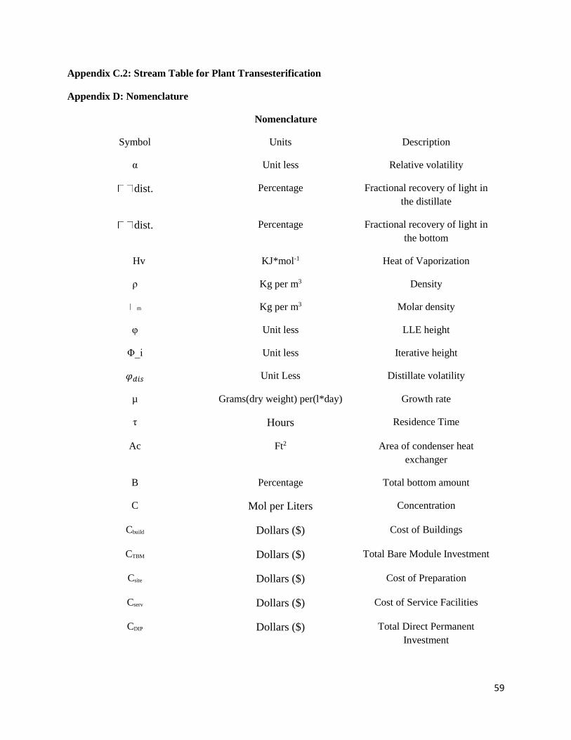
Appendix D: Nomenclature
Nomenclature
Symbol Units Description
α Unit less Relative volatility
dist. Percentage Fractional recovery of light in
the distillate
dist. Percentage Fractional recovery of light in
the bottom
Hv KJ*mol-1 Heat of Vaporization
ρ Kg per m3 Density
m Kg per m3 Molar density
φ Unit less LLE height
Φ_i Unit less Iterative height
𝜑𝑑𝑖𝑠 Unit Less Distillate volatility
µ Grams(dry weight) per(l*day) Growth rate
τ Hours Residence Time
Ac Ft2 Area of condenser heat
exchanger
B Percentage Total bottom amount
C Mol per Liters Concentration
Cbuild Dollars ($) Cost of Buildings
CTBM Dollars ($) Total Bare Module Investment
Csite Dollars ($) Cost of Preparation
Cserv Dollars ($) Cost of Service Facilities
CDIP Dollars ($) Total Direct Permanent
Investment
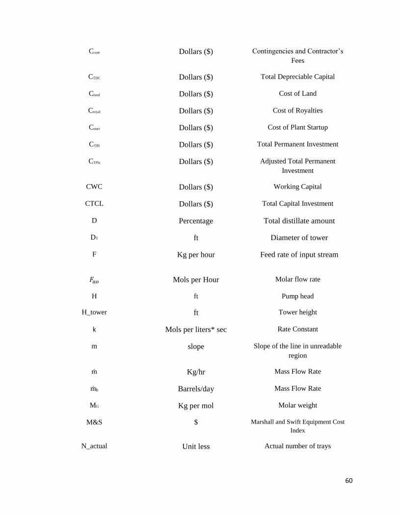
60
Ccont Dollars ($) Contingencies and Contractor’s
Fees
CTDC Dollars ($) Total Depreciable Capital
Cland Dollars ($) Cost of Land
Croyal Dollars ($) Cost of Royalties
Cstart Dollars ($) Cost of Plant Startup
CTPI Dollars ($) Total Permanent Investment
CTPla Dollars ($) Adjusted Total Permanent
Investment
CWC Dollars ($) Working Capital
CTCL Dollars ($) Total Capital Investment
D Percentage Total distillate amount
DT ft Diameter of tower
F Kg per hour Feed rate of input stream
𝐹𝑎𝑜 Mols per Hour Molar flow rate
H ft Pump head
H_tower ft Tower height
k Mols per liters* sec Rate Constant
m slope Slope of the line in unreadable
region
ṁ Kg/hr Mass Flow Rate
ṁb Barrels/day Mass Flow Rate
MG Kg per mol Molar weight
M&S $ Marshall and Swift Equipment Cost
Index
N_actual Unit less Actual number of trays
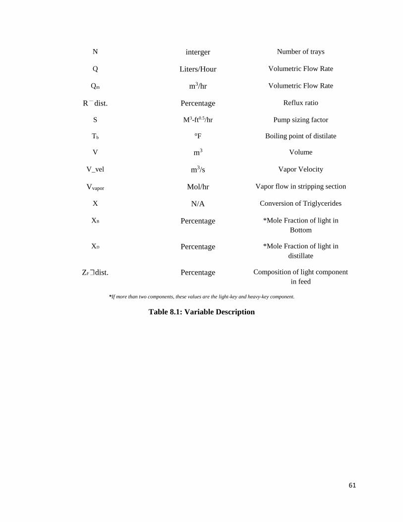
61
N interger Number of trays
Q Liters/Hour Volumetric Flow Rate
Qm m3/hr Volumetric Flow Rate
R dist. Percentage Reflux ratio
S M3-ft0.5/hr Pump sizing factor
Tb °F Boiling point of distilate
V m3 Volume
V_vel m3/s Vapor Velocity
Vvapor Mol/hr Vapor flow in stripping section
X N/A Conversion of Triglycerides
XB Percentage *Mole Fraction of light in
Bottom
XD Percentage *Mole Fraction of light in
distillate
ZF dist. Percentage Composition of light component
in feed
*If more than two components, these values are the light-key and heavy-key component.
Table 8.1: Variable Description
62
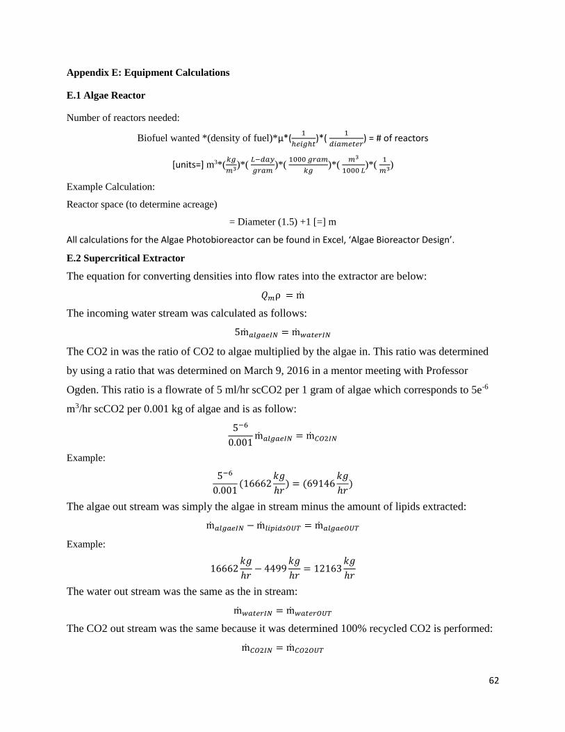
Appendix E: Equipment Calculations
E.1 Algae Reactor
Number of reactors needed:
Biofuel wanted *(density of fuel)*µ*(1
ℎ𝑒𝑖𝑔ℎ𝑡)*(
1
𝑑𝑖𝑎𝑚𝑒𝑡𝑒𝑟) = # of reactors
[units=] m3*(𝑘𝑔
𝑚3)*( 𝐿−𝑑𝑎𝑦
𝑔𝑟𝑎𝑚)*(
1000 𝑔𝑟𝑎𝑚
𝑘𝑔)*(
𝑚3
1000 𝐿)*(
1
𝑚3)
Example Calculation:
Reactor space (to determine acreage)
= Diameter (1.5) +1 [=] m
All calculations for the Algae Photobioreactor can be found in Excel, ‘Algae Bioreactor Design’.
E.2 Supercritical Extractor
The equation for converting densities into flow rates into the extractor are below:
𝑄𝑚ρ = ṁ
The incoming water stream was calculated as follows:
5ṁ𝑎𝑙𝑔𝑎𝑒𝐼𝑁 = ṁ𝑤𝑎𝑡𝑒𝑟𝐼𝑁
The CO2 in was the ratio of CO2 to algae multiplied by the algae in. This ratio was determined
by using a ratio that was determined on March 9, 2016 in a mentor meeting with Professor
Ogden. This ratio is a flowrate of 5 ml/hr scCO2 per 1 gram of algae which corresponds to 5e-6
m3/hr scCO2 per 0.001 kg of algae and is as follow:
5−6
0.001ṁ𝑎𝑙𝑔𝑎𝑒𝐼𝑁 = ṁ𝐶𝑂2𝐼𝑁
Example:
5−6
0.001(16662
𝑘𝑔
ℎ𝑟) = (69146
𝑘𝑔
ℎ𝑟)
The algae out stream was simply the algae in stream minus the amount of lipids extracted:
ṁ𝑎𝑙𝑔𝑎𝑒𝐼𝑁 − ṁ𝑙𝑖𝑝𝑖𝑑𝑠𝑂𝑈𝑇 = ṁ𝑎𝑙𝑔𝑎𝑒𝑂𝑈𝑇
Example:
16662𝑘𝑔
ℎ𝑟− 4499
𝑘𝑔
ℎ𝑟= 12163
𝑘𝑔
ℎ𝑟
The water out stream was the same as the in stream:
ṁ𝑤𝑎𝑡𝑒𝑟𝐼𝑁 = ṁ𝑤𝑎𝑡𝑒𝑟𝑂𝑈𝑇
The CO2 out stream was the same because it was determined 100% recycled CO2 is performed:
ṁ𝐶𝑂2𝐼𝑁 = ṁ𝐶𝑂2𝑂𝑈𝑇
63
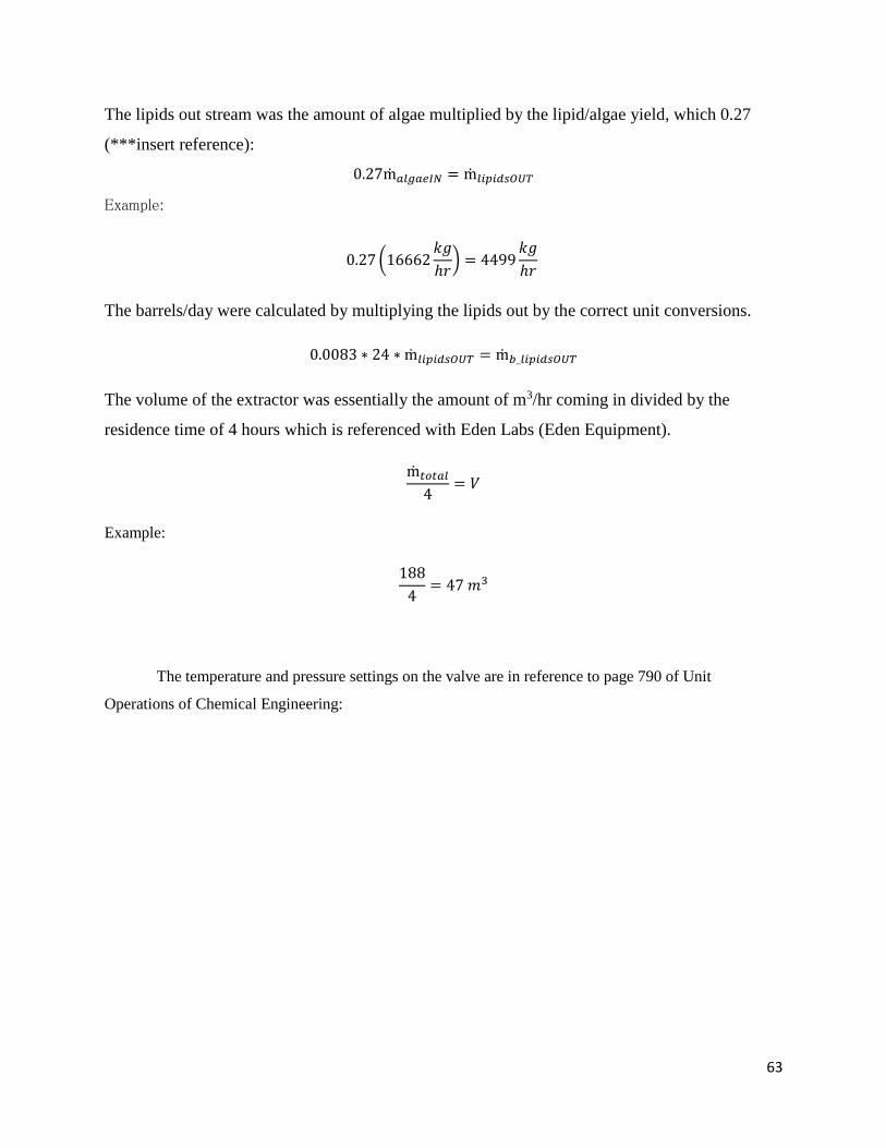
The lipids out stream was the amount of algae multiplied by the lipid/algae yield, which 0.27
(***insert reference):
0.27ṁ𝑎𝑙𝑔𝑎𝑒𝐼𝑁 = ṁ𝑙𝑖𝑝𝑖𝑑𝑠𝑂𝑈𝑇
Example:
0.27 (16662𝑘𝑔
ℎ𝑟) = 4499
𝑘𝑔
ℎ𝑟
The barrels/day were calculated by multiplying the lipids out by the correct unit conversions.
0.0083 ∗ 24 ∗ ṁ𝑙𝑖𝑝𝑖𝑑𝑠𝑂𝑈𝑇 = ṁ𝑏_𝑙𝑖𝑝𝑖𝑑𝑠𝑂𝑈𝑇
The volume of the extractor was essentially the amount of m3/hr coming in divided by the
residence time of 4 hours which is referenced with Eden Labs (Eden Equipment).
ṁ𝑡𝑜𝑡𝑎𝑙
4= 𝑉
Example:
188
4= 47 𝑚3
The temperature and pressure settings on the valve are in reference to page 790 of Unit
Operations of Chemical Engineering:
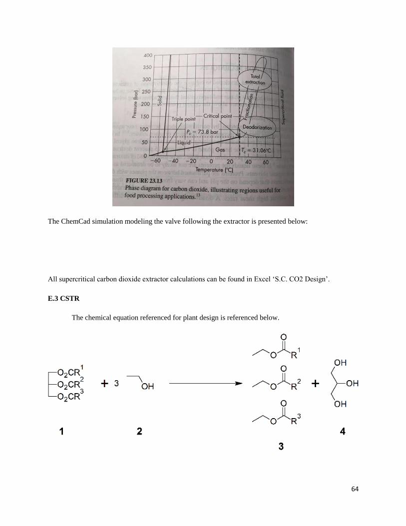
64
The ChemCad simulation modeling the valve following the extractor is presented below:
All supercritical carbon dioxide extractor calculations can be found in Excel ‘S.C. CO2 Design’.
E.3 CSTR
The chemical equation referenced for plant design is referenced below.
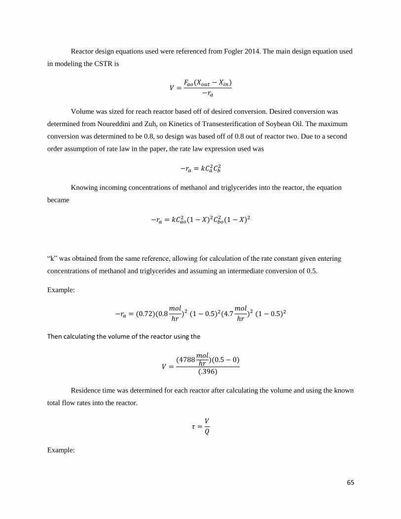
65
Reactor design equations used were referenced from Fogler 2014. The main design equation used
in modeling the CSTR is
𝑉 =𝐹𝑎𝑜(𝑋𝑜𝑢𝑡 − 𝑋𝑖𝑛)
−𝑟𝑎
Volume was sized for reach reactor based off of desired conversion. Desired conversion was
determined from Noureddini and Zuh, on Kinetics of Transesterification of Soybean Oil. The maximum
conversion was determined to be 0.8, so design was based off of 0.8 out of reactor two. Due to a second
order assumption of rate law in the paper, the rate law expression used was
−𝑟𝑎 = 𝑘𝐶𝑎2𝐶𝑏
2
Knowing incoming concentrations of methanol and triglycerides into the reactor, the equation
became
−𝑟𝑎 = 𝑘𝐶𝑎𝑜2 (1 − 𝑋)2𝐶𝑏𝑜
2 (1 − 𝑋)2
“k” was obtained from the same reference, allowing for calculation of the rate constant given entering
concentrations of methanol and triglycerides and assuming an intermediate conversion of 0.5.
Example:
−𝑟𝑎 = (0.72)(0.8𝑚𝑜𝑙
ℎ𝑟)2 (1 − 0.5)2(4.7
𝑚𝑜𝑙
ℎ𝑟)2 (1 − 0.5)2
Then calculating the volume of the reactor using the
𝑉 =(4788
𝑚𝑜𝑙ℎ𝑟
)(0.5 − 0)
(.396)
Residence time was determined for each reactor after calculating the volume and using the known
total flow rates into the reactor.
𝜏 =𝑉
𝑄
Example:
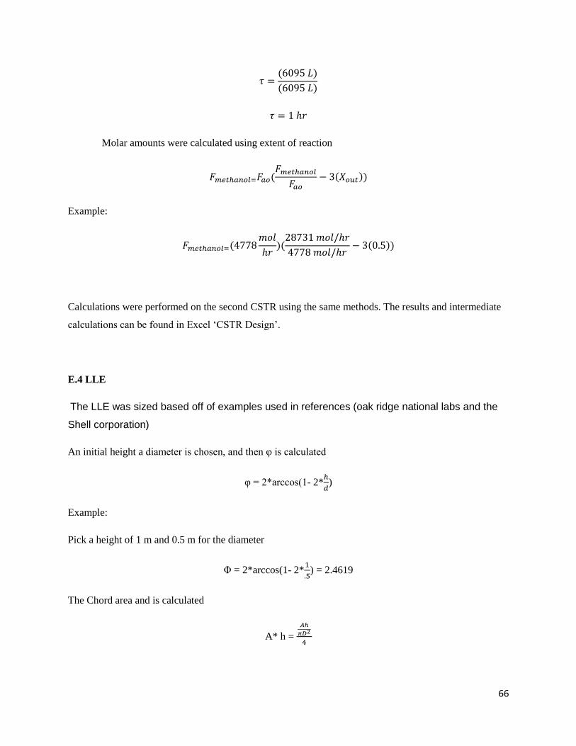
66
𝜏 =(6095 𝐿)
(6095 𝐿)
𝜏 = 1 ℎ𝑟
Molar amounts were calculated using extent of reaction
𝐹𝑚𝑒𝑡ℎ𝑎𝑛𝑜𝑙=𝐹𝑎𝑜(𝐹𝑚𝑒𝑡ℎ𝑎𝑛𝑜𝑙
𝐹𝑎𝑜− 3(𝑋𝑜𝑢𝑡))
Example:
𝐹𝑚𝑒𝑡ℎ𝑎𝑛𝑜𝑙=(4778𝑚𝑜𝑙
ℎ𝑟)(
28731 𝑚𝑜𝑙/ℎ𝑟
4778 𝑚𝑜𝑙/ℎ𝑟− 3(0.5))
Calculations were performed on the second CSTR using the same methods. The results and intermediate
calculations can be found in Excel ‘CSTR Design’.
E.4 LLE
The LLE was sized based off of examples used in references (oak ridge national labs and the
Shell corporation)
An initial height a diameter is chosen, and then φ is calculated
φ = 2*arccos(1- 2*ℎ
𝑑)
Example:
Pick a height of 1 m and 0.5 m for the diameter
Φ = 2*arccos(1- 2*1
.5) = 2.4619
The Chord area and is calculated
A* h =
𝐴ℎ
𝜋𝐷2
4
67
Solving for Ah yields
A h = 𝜋𝐷2
4∗ 𝐴∗ h
Example:
Assuming that the lower level of the system is going to be at 80% of the overall height
A h = 𝜋0.52
4∗ 0.8 = 0.157
The liquid height is estimated with
A* l =
𝐴𝐼
𝜋𝐷2
4
Solving for AI yields
A l = 𝜋𝐷2
4∗ 𝐴∗ l
Example:
Assuming that the lower level of the system is going to be at 20% of the overall height
A l = 𝜋0.52
4∗ 0.2 = 0.039
An iterative estimation is used to determine the proximity to an ideal answer
ϕi+1 = ϕi −2∗π∗A∗− ϕi +sinϕi
cosϕi −1
Example:
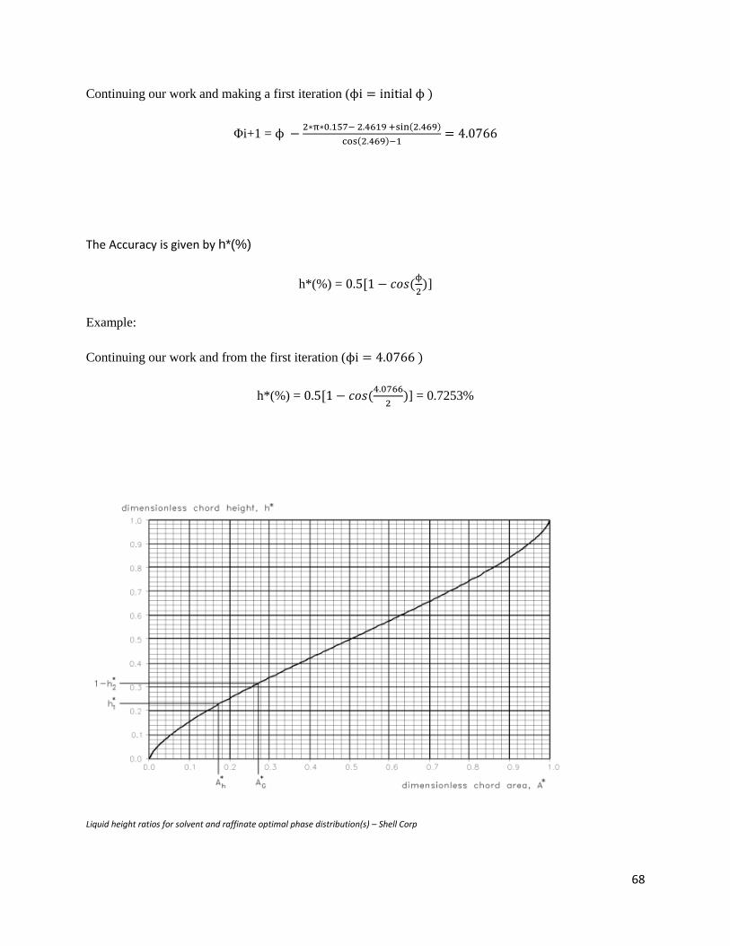
68
Continuing our work and making a first iteration (ϕi = initial ϕ )
Φi+1 = ϕ −2∗π∗0.157− 2.4619 +sin(2.469)
cos(2.469)−1= 4.0766
The Accuracy is given by h*(%)
h*(%) = 0.5[1 − 𝑐𝑜𝑠(ϕ
2)]
Example:
Continuing our work and from the first iteration (ϕi = 4.0766 )
h*(%) = 0.5[1 − 𝑐𝑜𝑠(4.0766
2)] = 0.7253%
Liquid height ratios for solvent and raffinate optimal phase distribution(s) – Shell Corp
69
All LLE calculations can be seen in Excel ‘Methyl Ester LLE Design’ and ‘LLE and Distillation’.
E.5 Distillation Columns
The equilibrium curve can be obtained by relating the relative volatility to the composition of the
liquid
y = α_dis.∗𝑥
(1+𝑥(𝛼−1)
Use underwood equation to determine the minimum reflux ratio
𝑉_ min = ∑(𝛼 ∗ 𝑍_𝑓)
(𝛼 − 𝜑𝑑𝑖𝑠)
Example:
Generating random variables to work with
α = .9, Z_f = 7, φ_dis = .7
Vmin = (0.9∗7)
(0.9−0.7) = 31.5
Mass balance shows that
Lmin = Vmin –D
Rmin = Vmin/D
We can choose a theoretical reflux ratio
Rtheo = 1.2*Rmin
Example:
We can calculate our Rmin
Assuming our total distillate amount (D), D = 0.9
70
Rmin = 31.5
.9= 35
Rtheo = 1.2*35 = 42
Determine the theoretical number of trays
N = ln (𝑆𝐹)
ln (𝛼
√1+𝑍_𝑓
𝑅
)
𝑆𝐹 =βdist ∗ δdist
((1 − 𝛿𝑑𝑖𝑠𝑡) ∗ (1 − 𝛽𝑑𝑖𝑠𝑡))
Example:
Βdis =0.999 , δdis =0.001
Calculating SF
𝑆𝐹 =0.999∗0.001
((1−0.001)∗(1−0.999)) =0.0999
Calculating N
N = ln (0.0999)
ln (0.9
√1+7
42
)= 12.62 ~13
Determine the actual number of trays with 60% efficiency
Nactual = 𝑁
0.6
Example:
Nactual = 13
0.6 = 21.6667 ~ 22
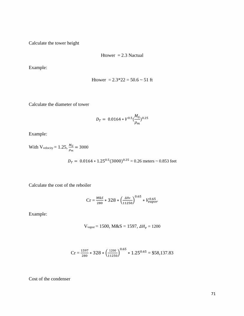
71
Calculate the tower height
Htower = 2.3 Nactual
Example:
Htower = 2.3*22 = 50.6 ~ 51 ft
Calculate the diameter of tower
𝐷𝑇 = 0.0164 ∗ 𝑉0.5(𝑀𝐺
𝜌𝑚)0.25
Example:
With Vvelocity = 1.25, 𝑀𝐺
𝜌𝑚= 3000
𝐷𝑇 = 0.0164 ∗ 1.250.5(3000)0.25 = 0.26 meters ~ 0.853 feet
Calculate the cost of the reboiler
Cr = 𝑀&𝑆
280∗ 328 ∗ (
ΔHv
11250)
0.65
∗ 𝑉𝑣𝑎𝑝𝑜𝑟0.65
Example:
Vvapor = 1500, M&S = 1597, 𝛥𝐻𝑣 = 1200
Cr = 1597
280∗ 328 ∗ (
1200
11250)
0.65
∗ 1.250.65 = $58,137.83
Cost of the condenser
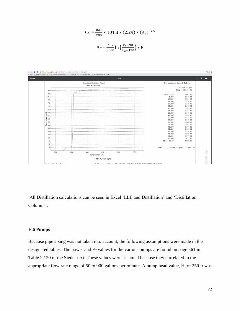
72
Cc = 𝑀&𝑆
280∗ 101.3 ∗ (2.29) ∗ (𝐴𝑐)0.65
AC = ΔHv
3000ln (
𝑇𝑏−90
𝑇𝑏−120) ∗ 𝑉
All Distillation calculations can be seen in Excel ‘LLE and Distillation’ and ‘Distillation
Columns’.
E.6 Pumps
Because pipe sizing was not taken into account, the following assumptions were made in the
designated tables. The power and FT values for the various pumps are found on page 561 in
Table 22.20 of the Sieder text. These values were assumed because they correlated to the
appropriate flow rate range of 50 to 900 gallons per minute. A pump head value, H, of 250 ft was
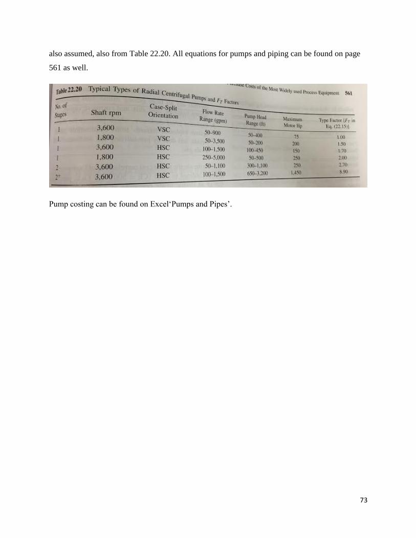
73
also assumed, also from Table 22.20. All equations for pumps and piping can be found on page
561 as well.
Pump costing can be found on Excel‘Pumps and Pipes’.
74
Appendix F: Economics Calculations
Capital Cost Calculations
Total bare module cost for onsite equipment:
CFE +CPM
Total bare module investment:
CTBM = CFE +CPM
Cost of buildings:
Cbuild = 0.1*CTBM
Cost of preparation:
Csite = 0.06*CTBM
Cost of service facilities:
Cserv = 0.05*CTBM
Total direct permanent investment:
CDIP = CTBM + Cbuild + Csite + Cserv
Contingencies and contractor's fees:
Ccont = 0.15*CDPI
Total depreciable capital:
CTDC = CDPI + Ccont
Cost of land:
75
Cland = 0.02*CTDC
Cost of royalties:
Croyal = 0.02*CTDC
Cost of plant startup:
Cstart = 0.15*CTDC
Total Permanent Investment:
CTPI = CTDC + Cland + Croyal + Cstart
Adjusted total permanent investment:
CTPla = 1.25*CTPI
Working capital:
CWC = 0.15*CTPla
Total Capital investment:
CTCL = CWC + CTPla
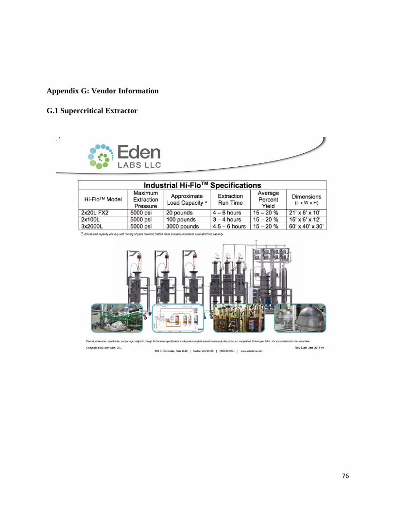
76
Appendix G: Vendor Information
G.1 Supercritical Extractor
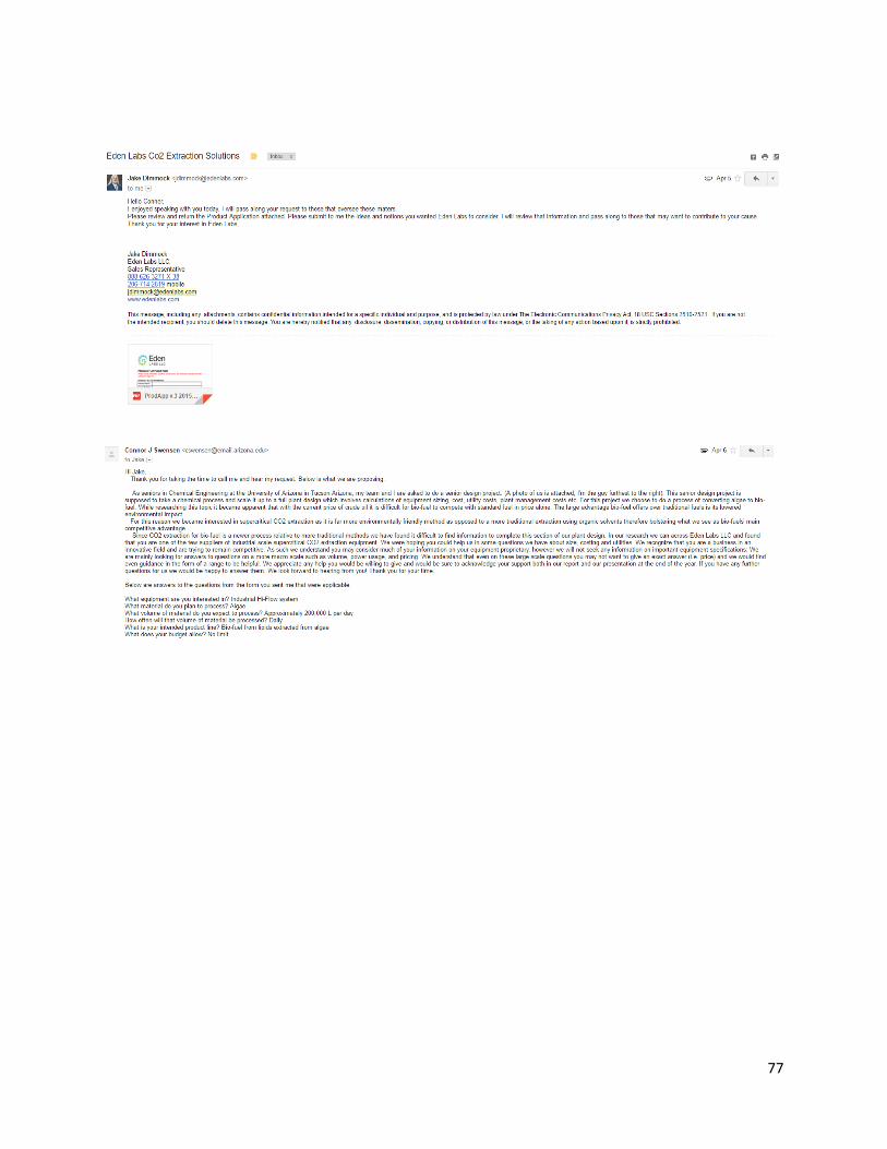
77
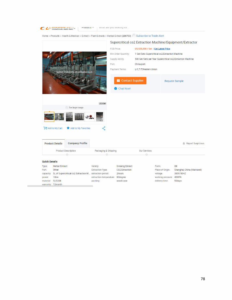
78
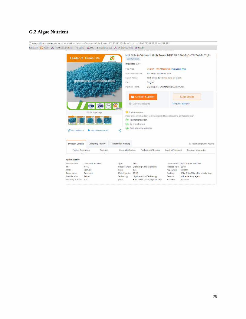
79
G.2 Algae Nutrient
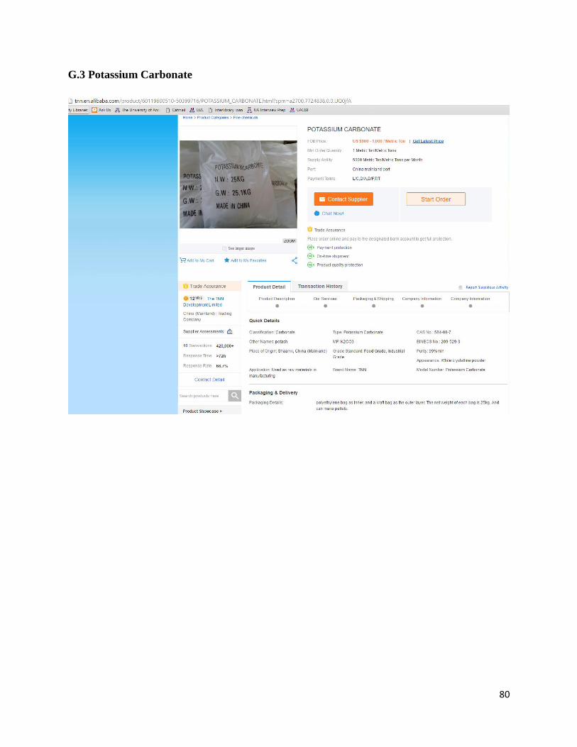
80
G.3 Potassium Carbonate
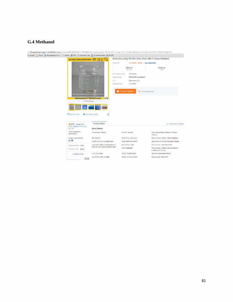
81
G.4 Methanol
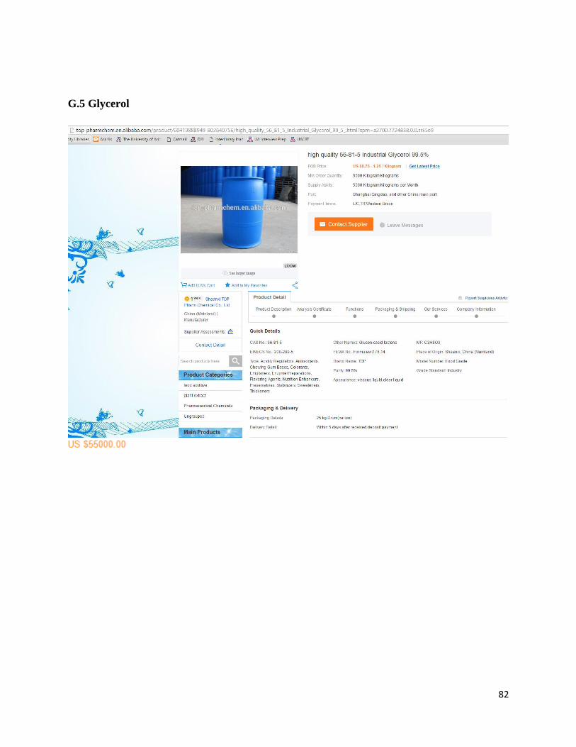
82
G.5 Glycerol
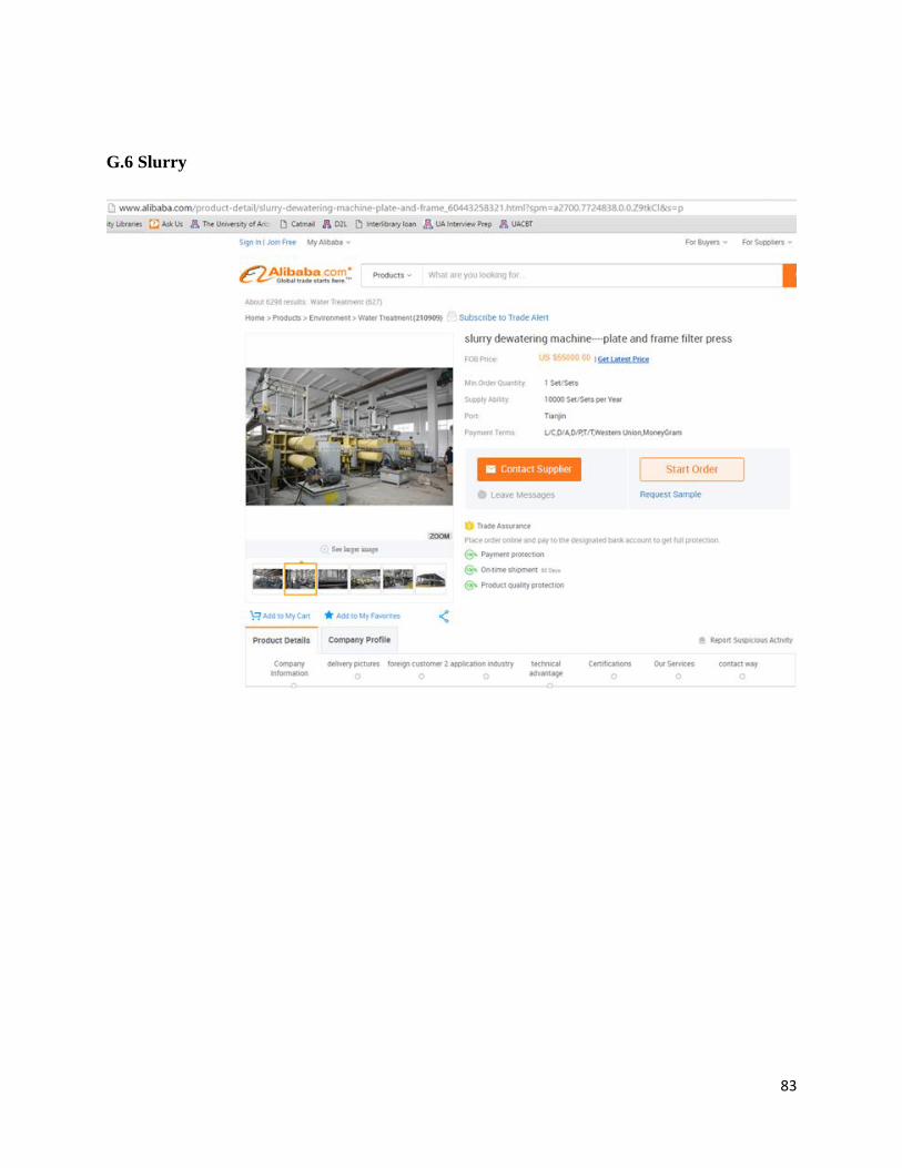
83
G.6 Slurry
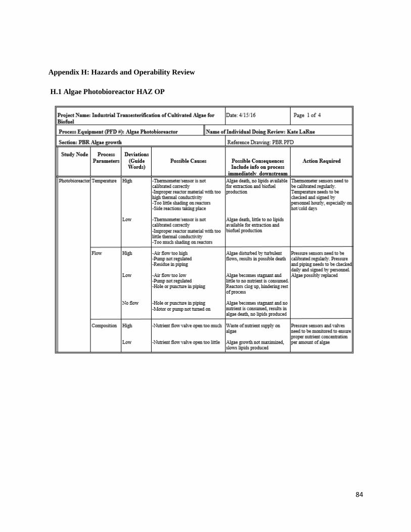
84
Appendix H: Hazards and Operability Review
H.1 Algae Photobioreactor HAZ OP
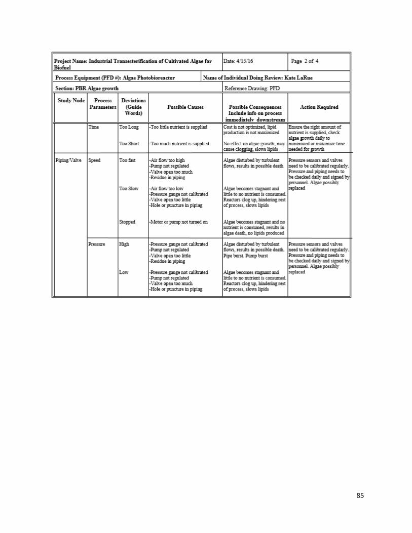
85
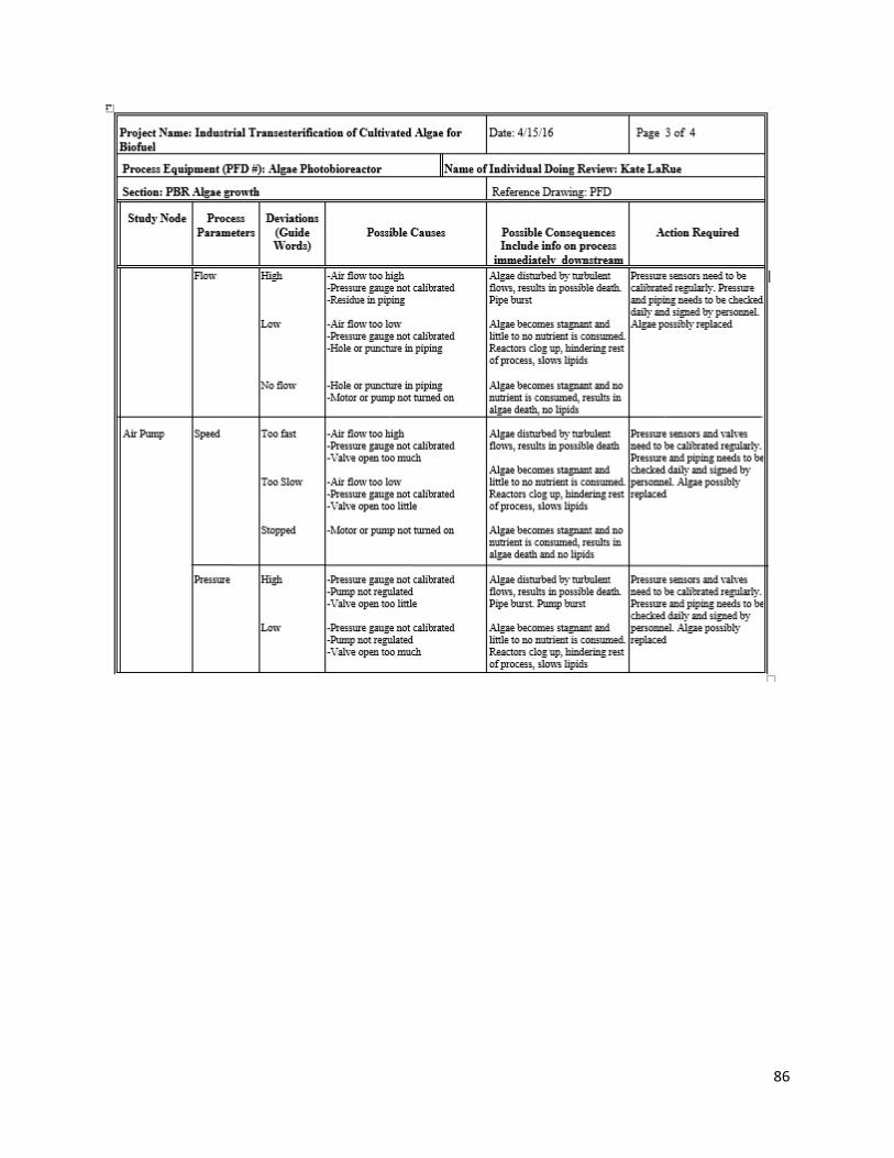
86
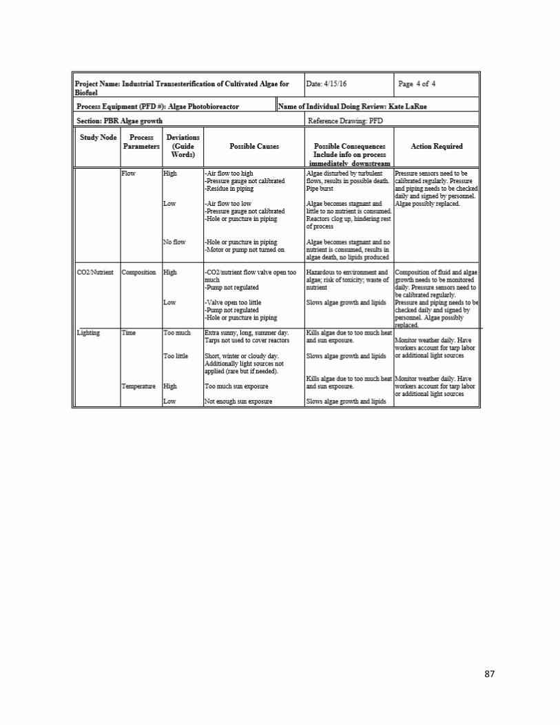
87
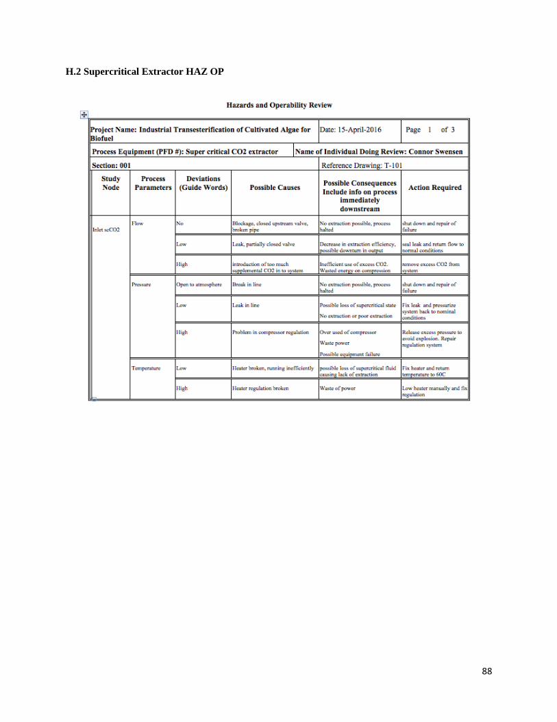
88
H.2 Supercritical Extractor HAZ OP
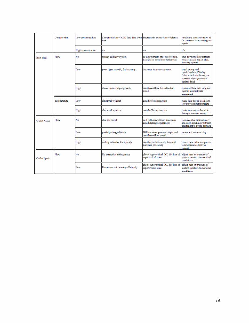
89
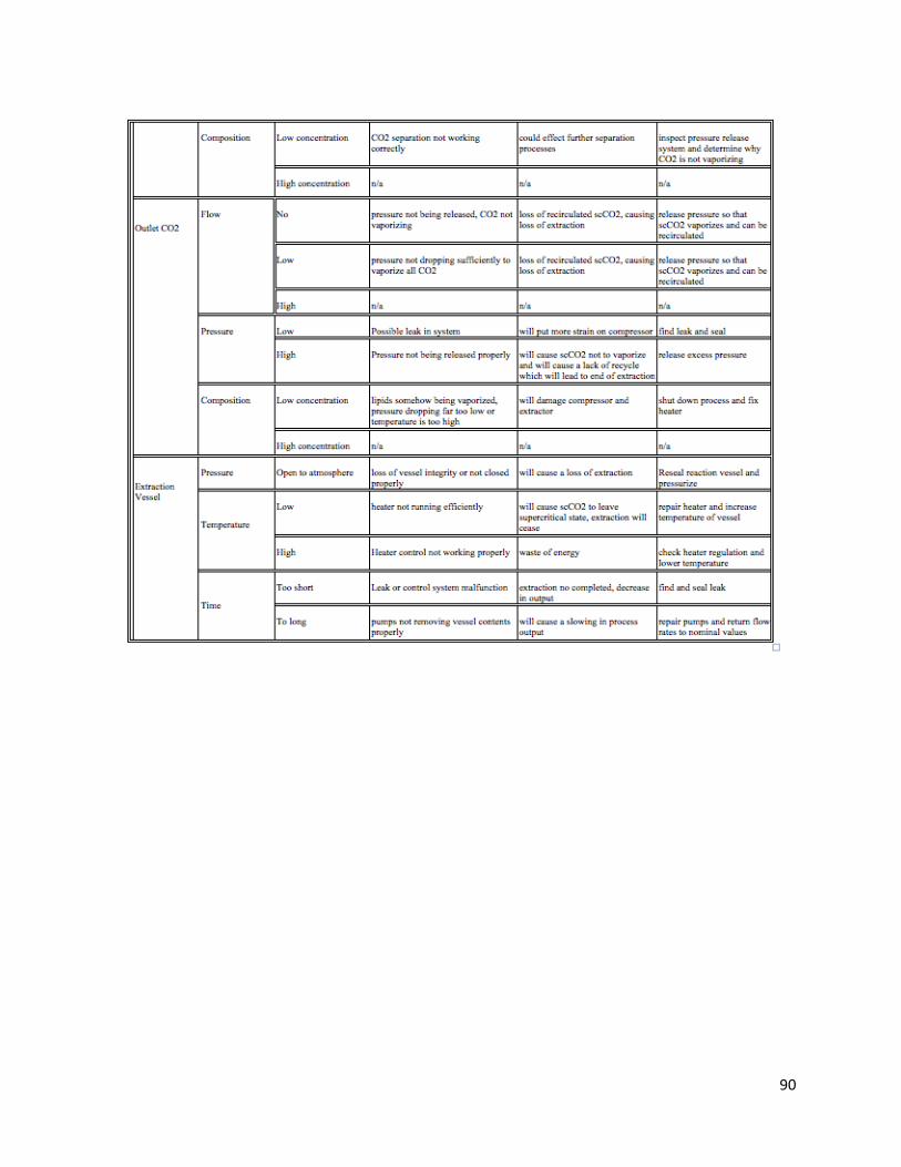
90
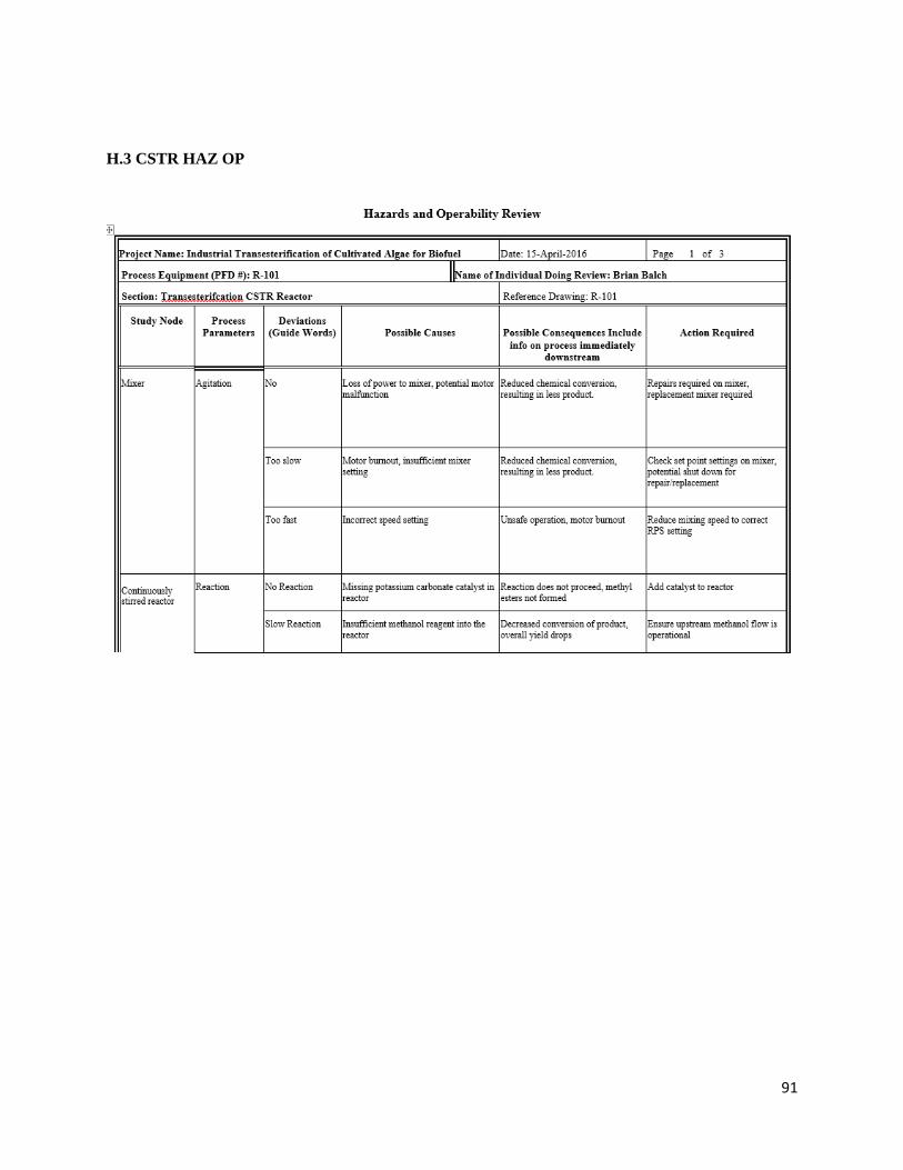
91
H.3 CSTR HAZ OP
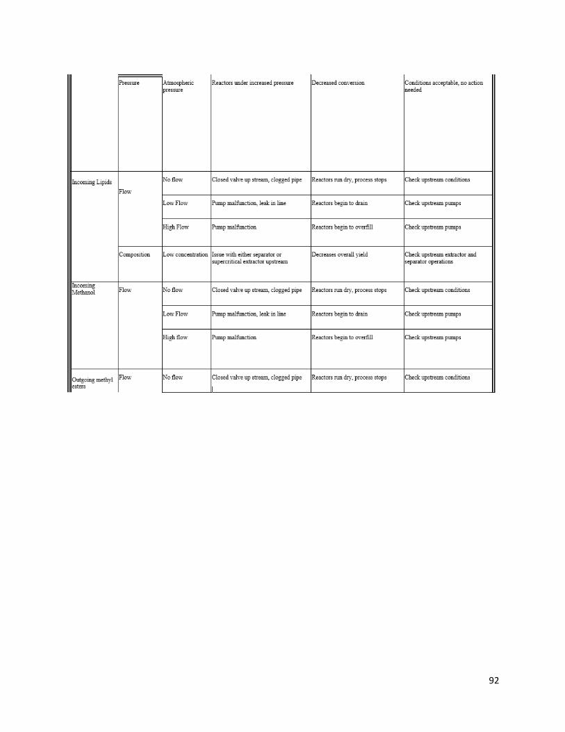
92
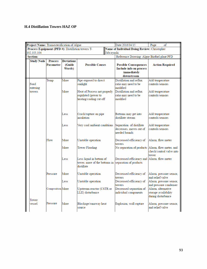
93
H.4 Distillation Towers HAZ OP
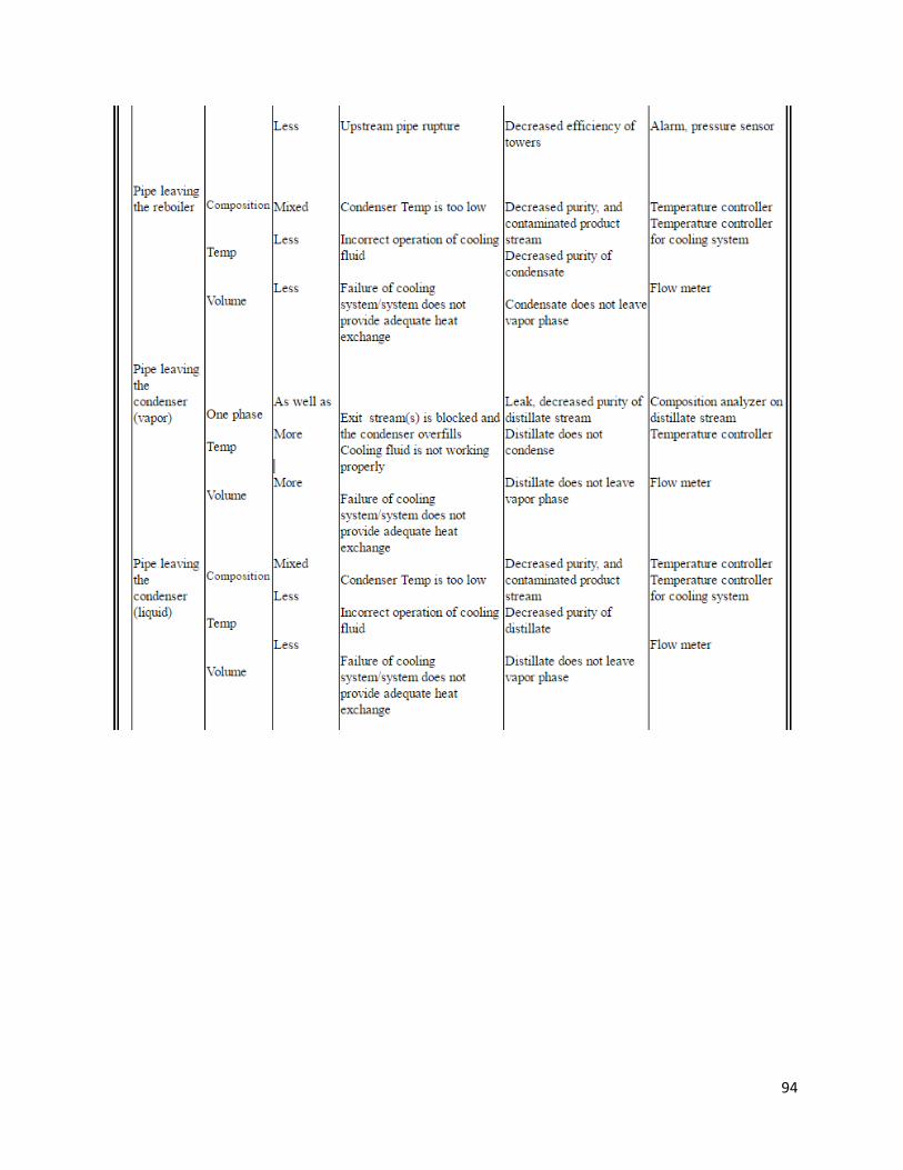
94
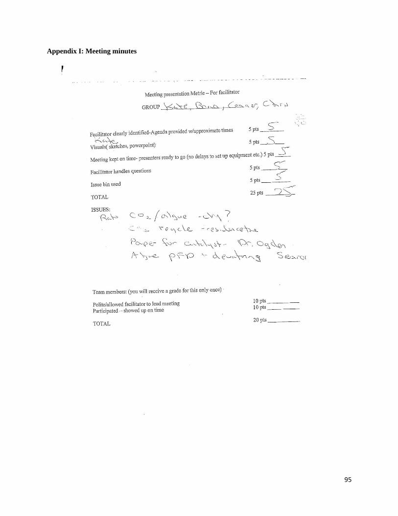
95
Appendix I: Meeting minutes
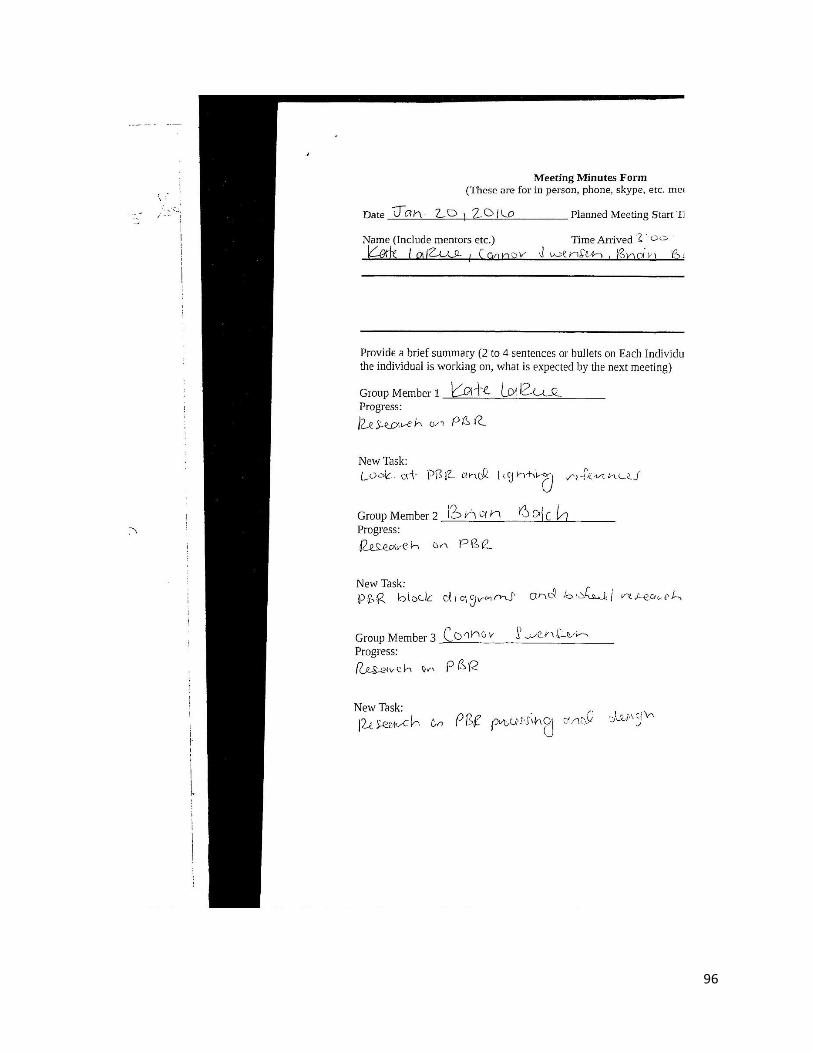
96
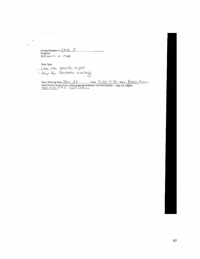
97
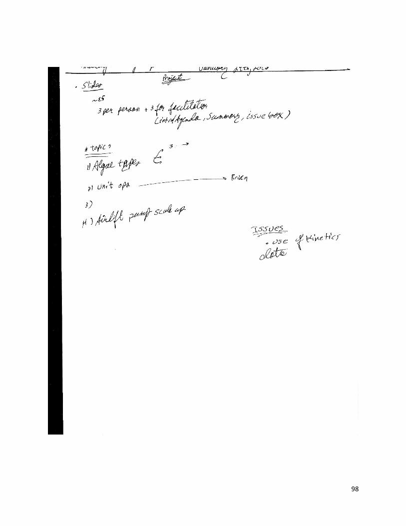
98
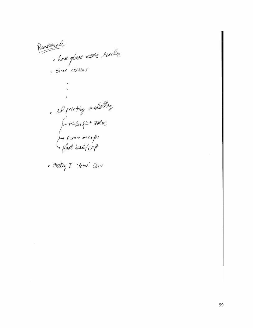
99
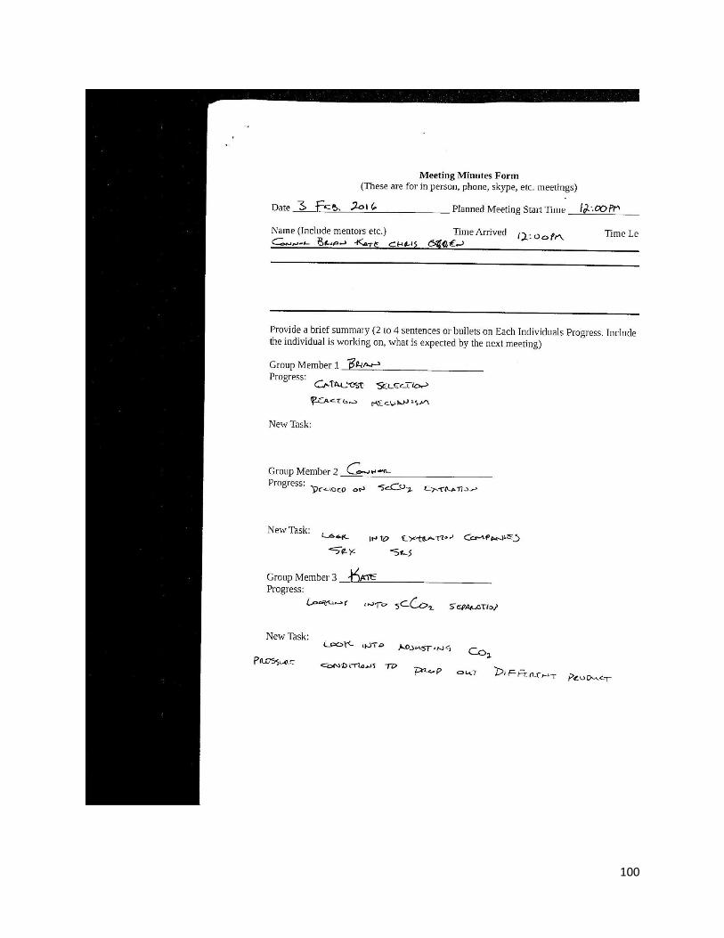
100
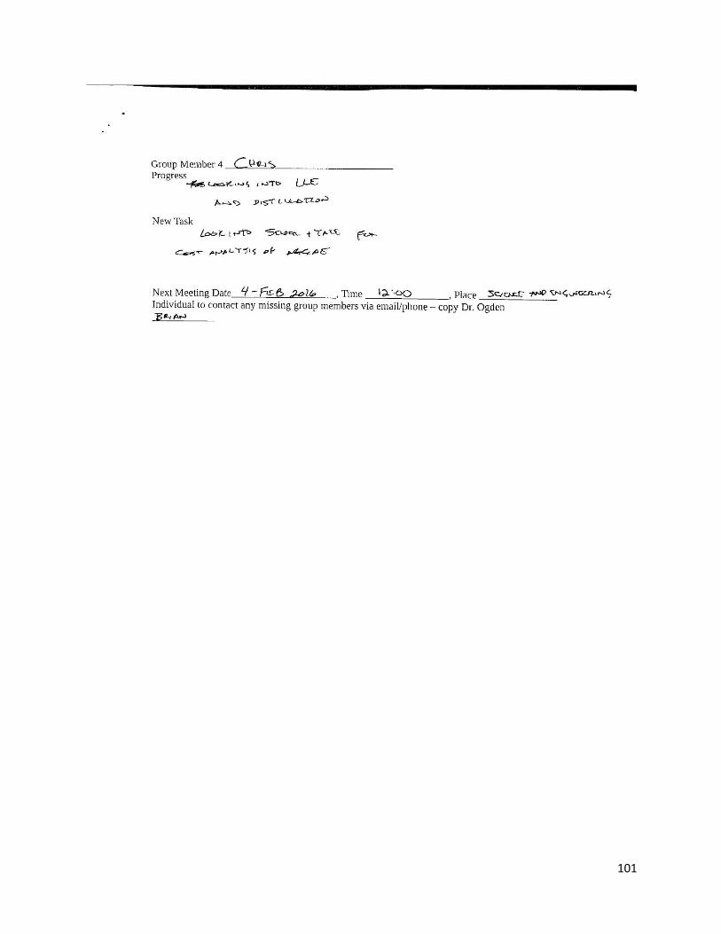
101
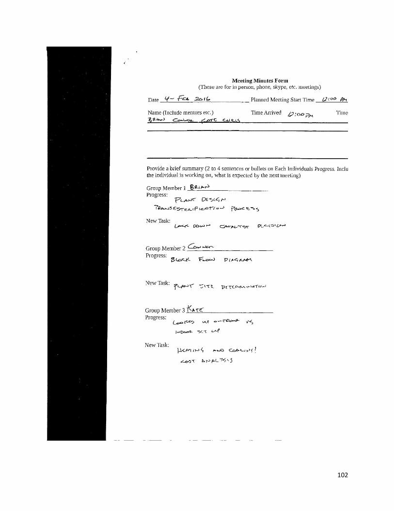
102
103
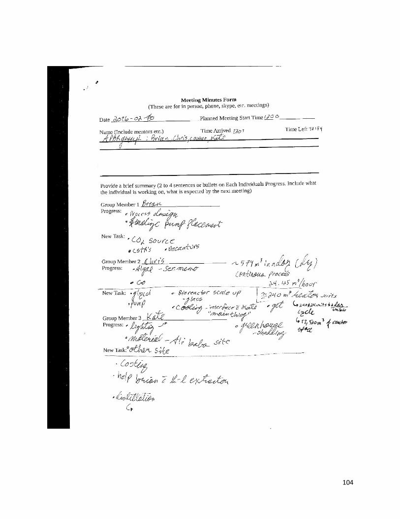
104
105
106
107
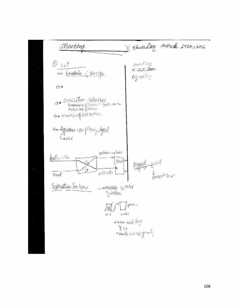
108
109
110
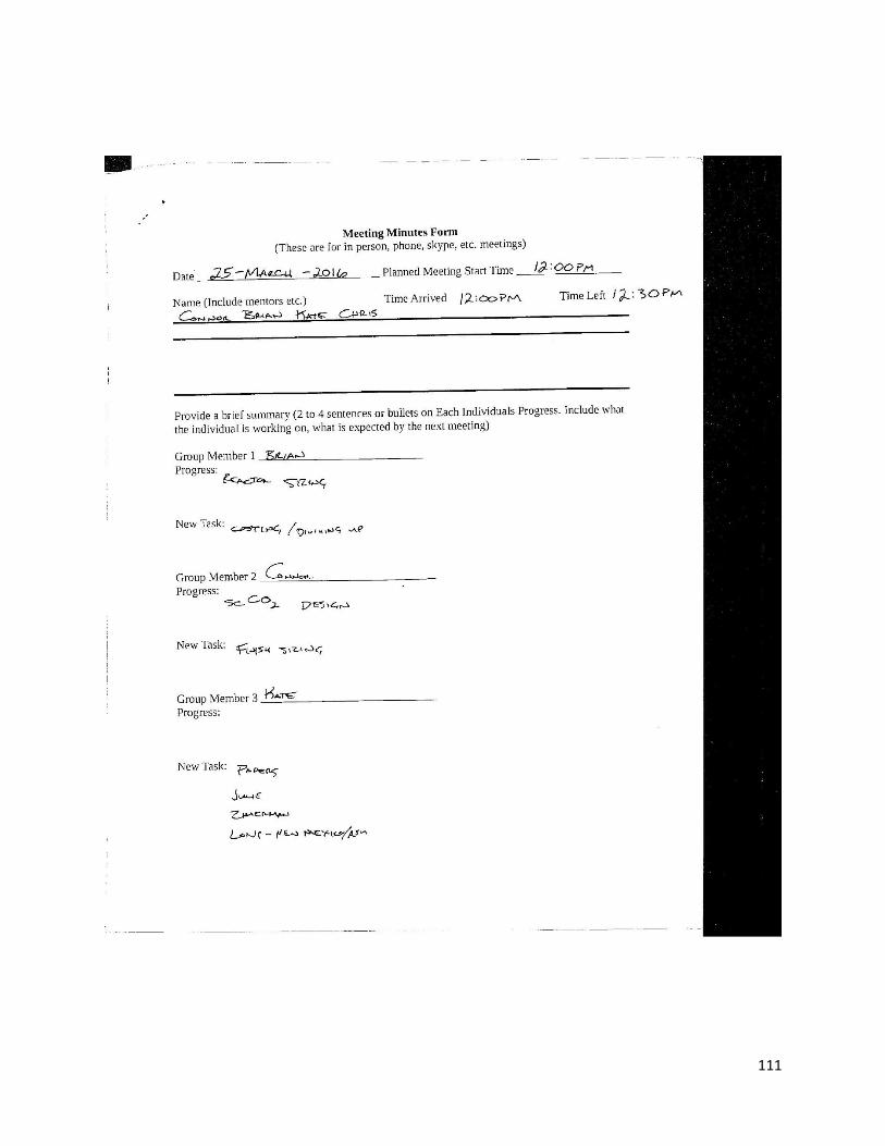
111
112

113
114
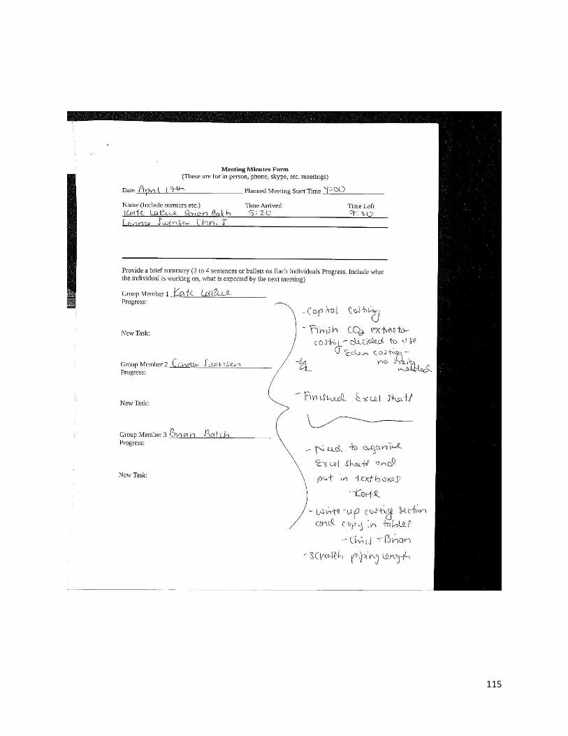
115
116