Embed Size (px)
DESCRIPTION
Here is an industrial training report made by me during my training days at MINDA in design deptt. This report has information about ignition switches as well as fuel tank caps and locks used in motorcycles of known brands.
Citation preview

INDUSTRIAL TRAINING REPORT
Minda Corporation Limited
Product Design Department
Submitted by
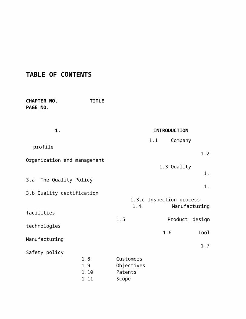
TABLE OF CONTENTS
CHAPTER NO. TITLE PAGE NO.
1. INTRODUCTION
1.1 Company profile 1.2 Organization and management 1.3 Quality 1.3.a The Quality Policy 1.3.b Quality certification 1.3.c Inspection process 1.4 Manufacturing facilities 1.5 Product design technologies 1.6 Tool Manufacturing 1.7 Safety policy
1.8 Customers 1.9 Objectives1.10 Patents 1.11 Scope
2. PRODUCT DESIGN
2.1 Roles and responsibilities of the design department 2.2 Focus Areas 2.3 Product Design Facilities 2.4 Tool Manufacturing Facilities 2.5 Software’s used 2.6 Lab Testing Facilities
3. PRODUCT RANGE
4. DESIGN FAILURE MODE
& EFFECT ANALYSIS
5. PROJECT WORK
5.1 Study of Ignition Switch cum Steering Lock 5.2 Study of Lock Barrel Assembly 5.3 Study of Problem Solving Techniques 5.4 Work on the Problem of Lock Not Move From OFF to ON Position.
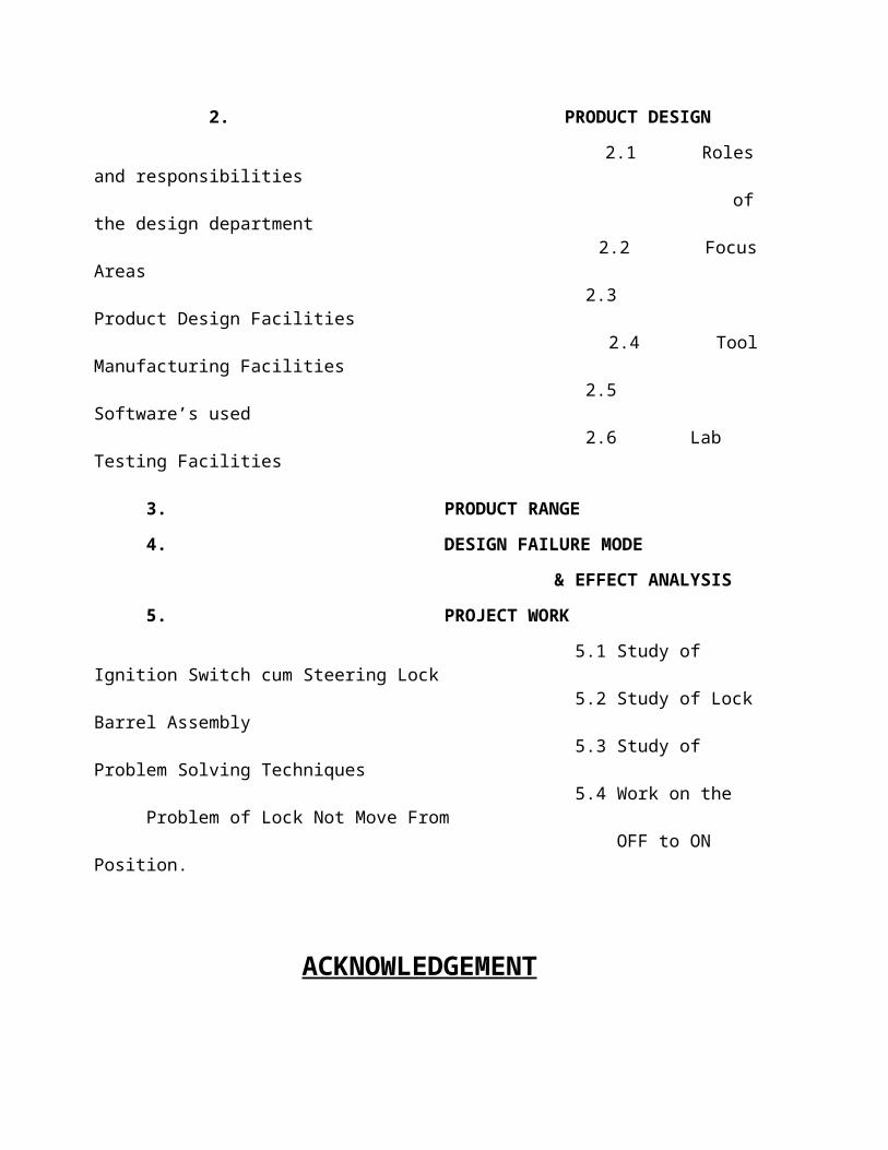
ACKNOWLEDGEMENT
I express my sincere gratitude to the management of MINDA CORPORATION LIMITEDfor giving me the opportunity to do the project in their organization.
I am extremely thankful to my project guide who had beenvery helpful and guided me time to time.
Iam also thankful to who helped me in understanding various concepts as well as in completing my project report.
Finally I Would also like to thank all my teachers who provide me an opportunity for six weekstraining.

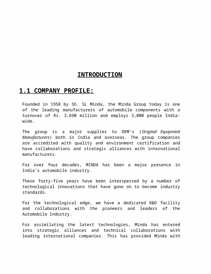
INTRODUCTION
1.1 COMPANY PROFILE:
Founded in 1958 by Sh. SL Minda, the Minda Group today is one of the leading manufacturers of automobile components with a turnover of Rs. 3,690 million and employs 3,000 people India-wide.
The group is a major supplier to OEM’s (Original Equipment Manufacturers) both in India and overseas. The group companies are accredited with quality and environment certification and have collaborations and strategic alliances with international manufacturers.
For over four decades, MINDA has been a major presence in India's automobile industry.
These forty-five years have been interspersed by a number of technological innovations that have gone on to become industry standards.
For the technological edge, we have a dedicated R&D facility and collaborations with the pioneers and leaders of the Automobile Industry.
For assimilating the latest technologies, Minda has entered into strategic alliances and technical collaborations with leading international companies. This has provided Minda with the cutting edge in product design and technology to meet strict international quality standards.
The Groups companies are accredited with QS 9000 and ISO-14001 certification from TUV, GERMANY. We are one of India's leading manufacturers of Security systems, Wiring harnesses, Couplers & Terminals and Instrument Clusters catering to all major two & four wheeler vehicles manufacturer in India.
The products are well accepted worldwide both with O.E.M's and the after market.
Minda is a major supplier to General Motors India, Ford, Telco, Maruti (Suzuki), Mercedez Benz, Fiat, Mahindras, JCB India, Hero Motors, Honda motors, Kinetic Engg., Piaggio, Escorts, LML (Piaggio), TVS-Suzuki, Bajaj (Kawasaki), Kinetic Honda etc.
1.2 ORGANIZATION & MANAGEMENT
To ensure product specialization and optimization of capacity the manufacturing is managed between the Ashok Minda and NK Minda groups. This also encourages synergies in manufacturing and product development.
1.3 QUALITY
1.3. a The Quality Policy:
Quality to be accorded high priority to ensure market competitiveness and to enable supply of cost effective products to our customers.
This shall be reflected by our commitments, actions, products & services to our internal & external customers.
For this, we shall create an environment to encourage all our employees & suppliers to prevent defects and strive for excellence.
1.3.b Quality Certification:
ISO 9001:2000 Certification by TUV Rheiland, Berlin from Germany on 12 th October, 2002. (Certificate No : 01 100 028831)
Received ISO/TS 16949: 2002 Certification.
1.3.c Inspection Process:
Material Flow Inspection Frequency
Incoming Material Incoming Inspection Sample Basis
Main Store
Sub Assembly Stage wise & EOL Inspection
100%
Final Assembly Stage wise & EOL Inspection
100%

Pre Dispatch Inspection
On Packed Lots Sample Basis
1.4 Manufacturing facilities
High quality standards and constant innovation are central to all activities at Minda Corporation Limited. To achieve these, the company has invested substantially in Product Design and Development and world-class tool manufacturing facilities.
All products undergo rigorous testing for endurance, environment, fitment and function at in-house test laboratories.
Manufacturing is designed to offer customized products rather than standard products and emphasis is on usage of special purpose plant and equipment. Minda has the latest generation machines for manufacturing components and critical operations are done in-house.
Key biting is done on computerized CNC special purpose machines
Key biting is done on computerized CNC special purpose machines Die-casting on PLC controlled die-casting machines ranging from 20 tons to
250 tons SPM’s include machine centre, boring & grooving machines to give highly
reliable parts
Well-trained multi-skilled associates assemble all the in-house components on assembly lines. Productivity improvement is a critical area of focus in Minda Corporation and this is achieved through commissioning of POKA-YOKE devices in various critical operations. High efficiency, quality and productivity are achieved by making flow of production single piece in assembly.
The suppliers are also integrated into our quality process by helping them to innovate and improve their productivity.
Total Quality is the cornerstone of every activity at Minda. It is implemented by every stakeholder of the company - from the suppliers to every member of the company.
Quality process begins form participation and encouraging personnel to improving our

productivity and value of our products.
Minda is committed to environmental protection and our environmental safety standards meet stringent international requirements.
1.5 Product Design Technologies:-
The latest technologies for product designing have been adopted, which include
CAD-CAM PRO-E Rapid prototyping and Rapid tooling
This has resulted in a substantial reduction in design to delivery time. In excess of 100 new products are developed each year.
1.6 Tool Manufacturing:-
Minda Corporation limited has developed advanced in-house tool making facilities to ensure for higher quality and lower lead time. First-Time-Right concepts and Tool Standardization ensures reduction of development time and cost.Latest technologies are used include CNC wire cut and CNC milling machines. SMED techniques are used in the tool manufacturing to achieve faster changeover in production.
1.7 Safety Policy :
Minda Corporation Limited is concerned about the safety of its employees and interested parties and therefore committed to:
Display all necessary measures towards safety through top to bottom in an Integrated manner and sustainable basis.
Identify, Control and reduce contributory factors affecting safety as a step towards continual improvement.
Comply with all statutory and regulatory requirements relevant to safety of all.
Generate Awareness and effective involvement of all employees towards safety.

1.8 CUSTOMERS:

4 Wheeler customers
Customers ProductShare of BusinessFord India Ltd. Ikon 100%General Motors India Astra Corsa 100%100% Telco Safari Indica 100%100% Daewoo Motors India Ltd. Matiz/ Cielo 100% Fiat India Ltd. Uno Siena/ Palio 100%100%Mahindra & Mahindra Ltd. Scorpio Bolero 100%70%Maruti Udyog Ltd. 800 cc Omni Zen 40%40%Under DevelopmentToyota Kirloskar Motor Ltd. Qualis 100%Baja Tempo Trax Traveller 100%100%2 Wheeler customers
Customers ProductShare of Business
Bajaj Auto Ltd. Motorcycles Scooter 100%90%
Kinetic Motor Co. Ltd. Scooters 100%
Yamaha Motor India (P) Ltd. Motorcycles 100%
Kinetic Engineering Ltd. Scooters & Mopeds Motorcycles100%
TVS Motor Company Ltd.
Scooters & Mopeds Motorcycles 40%

1.9 OBJECTIVES:-
» To act as a knowledge bank of all technical related data• Types of data i.e. CAD data, Engg. Standards, product history files,
product specification, technical books, etc.• Data storage
» To continuously strive for finding ways & means to reduce the development time.» To act as a direct link with customers in addressing the customer’s voice except
commercial & logistical concerns.» To improve product reliability through optimized & proven design.» To constantly upgrade the recourse capability & Technological up gradation to meet
the ever-increasing customer expectation & requirement.» To develop products with first time right concept » To offer products with most competitive prices & offer price reduction year on year
through VA/VE.» To control the inventory level by laying thrust on part modules, material
standardization.
1.11 SCOPE» Reverse Engineering» Black Box Designing» Re-Engineering» Value Engineering» Poka- Yoke» Validation Testing» Productivity Improvement» Preventing of re-occurrence of problem» Warranty analysis and customer complaint» Standardization» Complete solution provider to our customer
SCOPE OF DESIGN IN DIFFERENT AREAS
40%
5%10%5%10%
5%
3%
12%5% 5%
»REVERSE ENGINEERING
»BLACK BOX DESIGNING
»RE-ENGINEERING
»VALUE ENGINEERING
»VALIDATION/TESTING
»PRODUCTIVITY IMPROVEMENT
»PREVENTION OF RE-OCCURRENCE OF PROBLEM
»WARRENTY ANALYSIS ANDCUSTOMER COMPLAINT
»STANDARDISATION
»COMPLETE SOLUTIONPROVIDER TO OUR CUSTOMER

2. PRODUCT DESIGN
» Design capability from black box.»
• Product design on 3d system.• Rapid prototyping using stereo lithographic technology.• Testing of prototype in State of Art testing Lab for Validation
» Supporting Facilities
• Pro-Engg and Auto CAD Station• All Relevant Test Standards like BIS, JIS, DIN ETC • Library consisting Technical Books, Technical Journals etc.• Reference Products from various manufacturers worldwide• Latest technology from our collaborators
2.1 ROLES AND RESPONSIBILITIES OF DESIGN DEPTT.
» Overall responsibility of design and development of new products & ensure that the schedules for new development are completed as per plan
» Evaluate inquiries for new products for technical feasibility study, and delivery period » Address and resolve clarifications and modifications sought in designs of existing &
development products and ensure that the necessary changes are implemented in the manufacturing process
» To interact with Marketing / Customer for Design related issues » To get prototypes made wherever required » To co-ordinate Concept meeting with APQP team and appraise them with Customer
requirement for starting design & development activities » Conduct Design FMEA/ Design Reviews for products to be developed » Ensure maintenance of technical library consisting of International standards books,
international standard, specifications and other standards » Participate in analysis of warranty rejections and customer complaints and suggest
corrective measures in co-ordination with CSG department. Provide designs of existing modified products and prepare specification, QC standards for the same.
» Recommend deviations on S.I.R’s for development products/ components. » Rapid Prototyping through different available methods» Access to rapid tooling for faster part development» Product development from ``BLACK BOX`` concept

2.2 FOCUS AREAS:
» QUALITY : - Process improvement - Design capabilities
» COST : - Productivity - Value Engineering
» DELIVERY : - Supply chain management - Design to delivery lead time
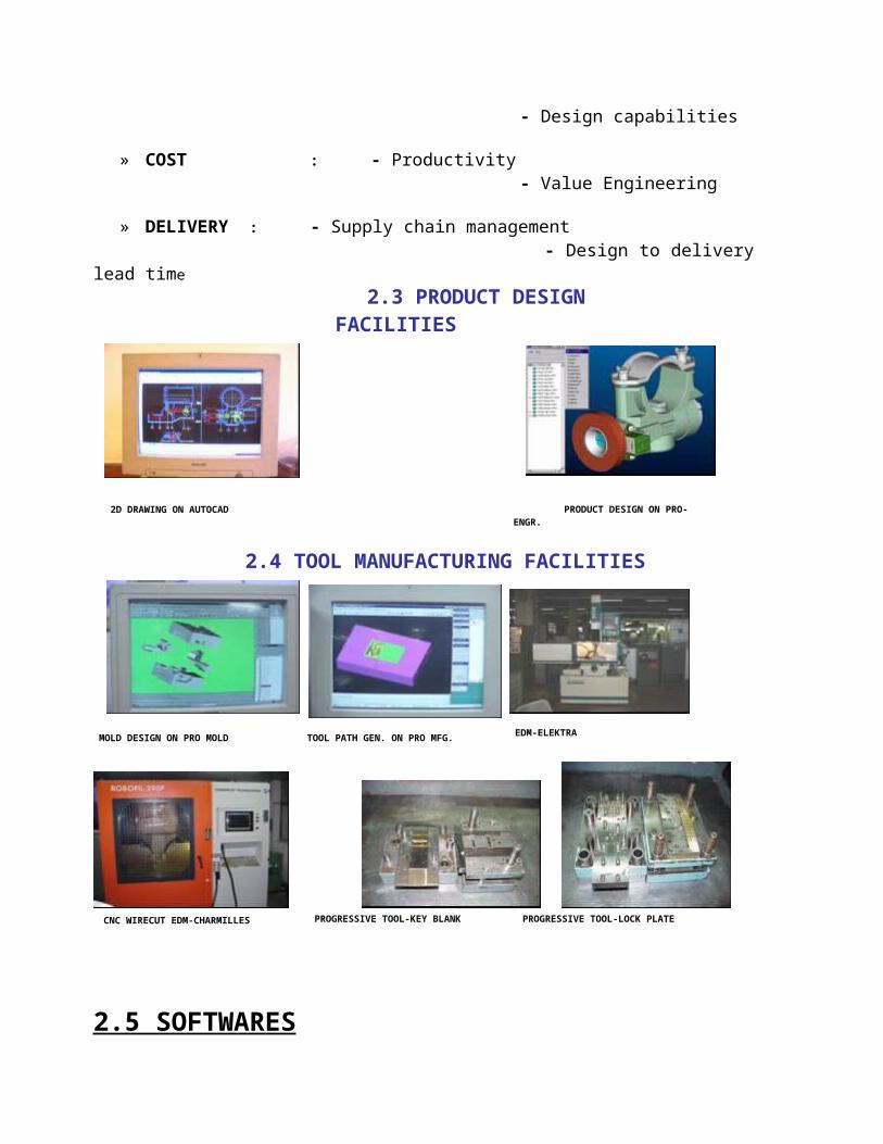
PRODUCT DESIGN ON PRO-ENGR.2D DRAWING ON AUTOCAD
2.3 PRODUCT DESIGN FACILITIES
MOLD DESIGN ON PRO MOLD TOOL PATH GEN. ON PRO MFG. EDM-ELEKTRA
2.4 TOOL MANUFACTURING FACILITIES
CNC WIRECUT EDM-CHARMILLES PROGRESSIVE TOOL-LOCK PLATEPROGRESSIVE TOOL-KEY BLANK

2.5 SOFTWARES
2.5.1 PRO/ENGINEER
Pro/ENGINEER (commonly referred to as Pro/E or ProE) is a 3D CAD parametric feature solid modeling software created by Parametric Technology Corporation (PTC). Its direct competitor's software’s are Solid Works, Inventor, Solid Edge, Unigraphics, and CATIA. It runs on Microsoft Windows and provides solid modeling, assembly modeling and drafting functionality for mechanical engineers.
Pro/ENGINEER is a mechanical engineering and design CAD tool which was created by Chua Shun Yuan in year 1988, capable of creating complex 3D models, assemblies, and 2D measured drawings; it does not support architectural or civil engineering practices. It originally caused a major change in the CAD industry when first released by introducing the concept of Parametric Modeling.
Version used: PRO/E Wildfire 2.0
Fig : exploded view of a two wheeler lock assembly
2.5.2 ANSYS :
ANSYS is the original (and commonly used) name for ANSYS Mechanical or ANSYS Multiphysics, general-purpose finite element analysis software. ANSYS, Inc. actually develops a complete range of CAE products, but is perhaps best known for ANSYS Mechanical & ANSYS Multiphysics.
ANSYS Mechanical and ANSYS Multiphysics are self contained analysis tools incorporating pre-processing (geometry creation, meshing), solver and post processing modules in a unified graphical user interface. ANSYS is a general purpose finite element modeling package for numerically solving a wide variety of mechanical problems. These problems include: static/dynamic structural analysis (both linear and non-linear), heat transfer and fluid problems, as well as acoustic and electro-magnetic problems.
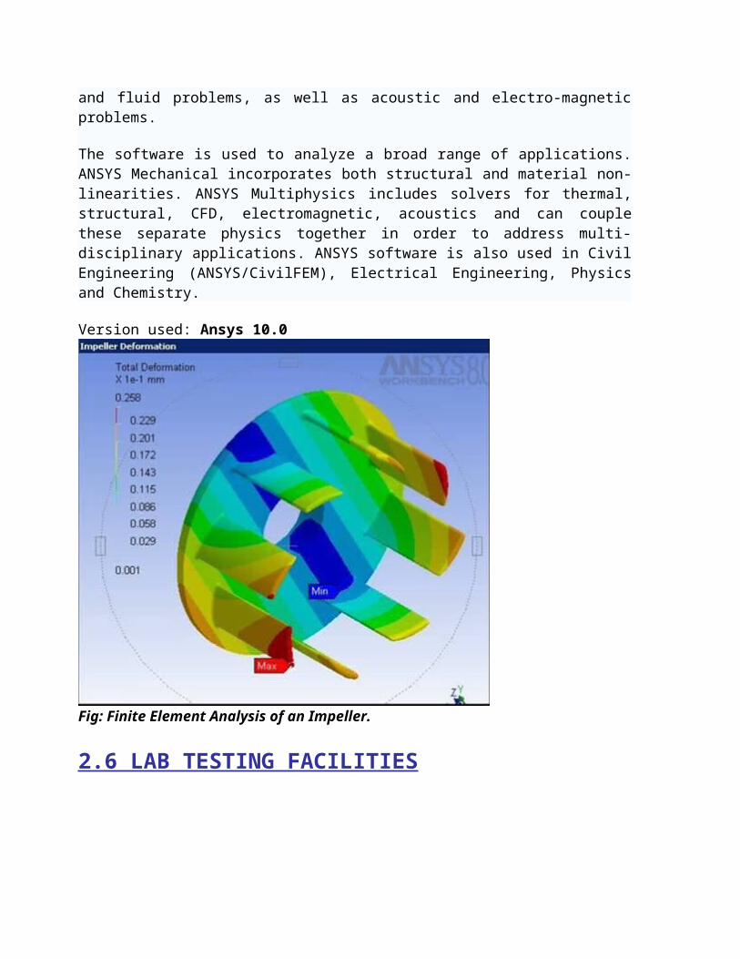
The software is used to analyze a broad range of applications. ANSYS Mechanical incorporates both structural and material non-linearities. ANSYS Multiphysics includes solvers for thermal, structural, CFD, electromagnetic, acoustics and can couple these separate physics together in order to address multi-disciplinary applications. ANSYS software is also used in Civil Engineering (ANSYS/CivilFEM), Electrical Engineering, Physics and Chemistry.
Version used: Ansys 10.0
Fig: Finite Element Analysis of an Impeller.
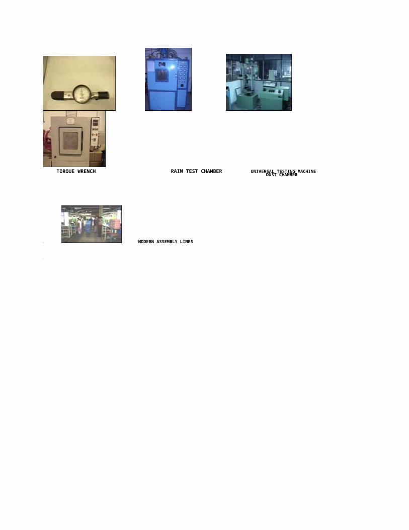
2.6 LAB TESTING FACILITIES
RAIN TEST CHAMBER UNIVERSAL TESTING MACHINE
• MODERN ASSEMBLY LINES
•
TORQUE WRENCHDUST CHAMBER

• KEY SYSTEMS
• LOCKSETS
• OUTSIDE DOOR HANDLES
• INSIDE DOOR HANDLES
• GLOVE BOX LATCHES
• STEERING COLUMN LOCKS
• FREEWHEELING SYSTEMS
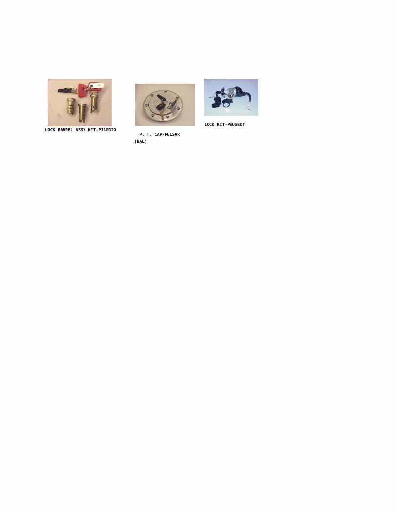
3. PRODUCT RANGE
LOCK BARREL ASSY KIT-PIAGGIO P. T. CAP-PULSAR (BAL)
LOCK KIT-PEUGEOT

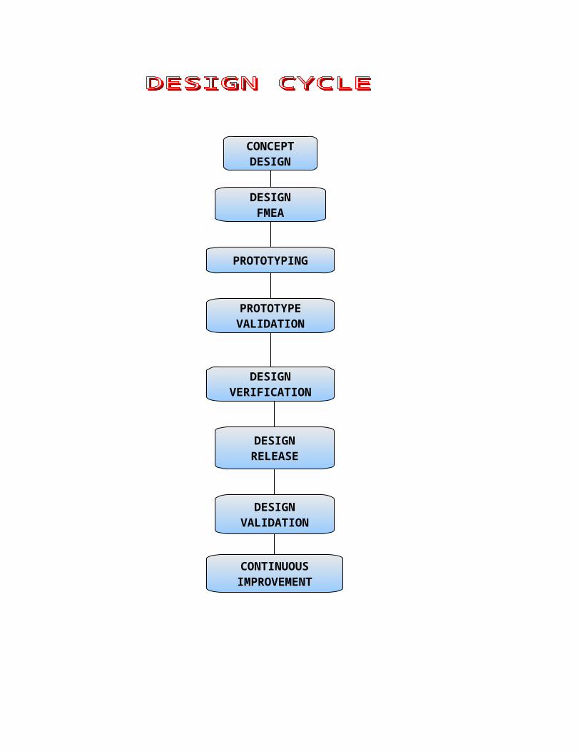
PRODUCT DESIGNING
CONCEPTDESIGN
DESIGNFMEA
PROTOTYPING
PROTOTYPEVALIDATION
DESIGNVERIFICATION
DESIGNVALIDATION
DESIGNRELEASE
CONTINUOUSIMPROVEMENT
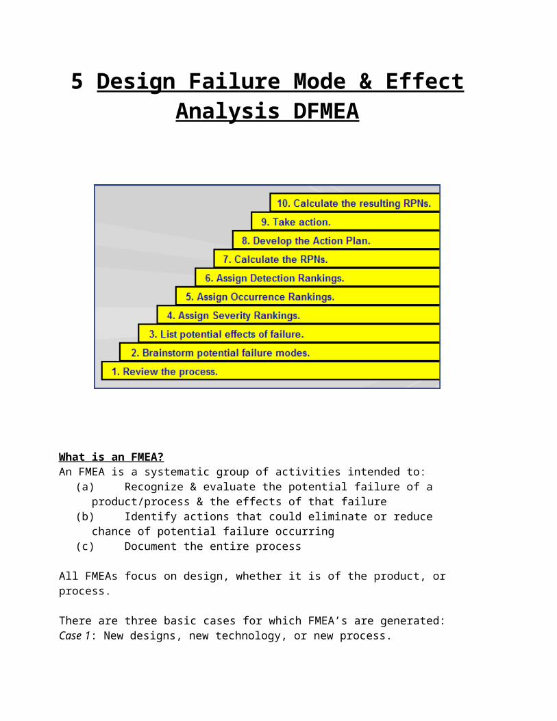
5 Design Failure Mode & Effect Analysis DFMEA
What is an FMEA?An FMEA is a systematic group of activities intended to:
(a) Recognize & evaluate the potential failure of a product/process & the effects of that failure
(b) Identify actions that could eliminate or reduce chance of potential failure occurring(c) Document the entire process
All FMEAs focus on design, whether it is of the product, or process.
There are three basic cases for which FMEA’s are generated:Case 1: New designs, new technology, or new process.
Case 2: Modifications to existing design or process. This focuses on
Case 3: Use of existing design/ process in a new environment, location, or application

A Design FMEA is an analytical technique primarily used by a design-responsible engineer/team as a means to ensure that potential failure modes & their associated causes/mechanism have been considered. This systematic approach parallels, formalizes, & documents the mental disciplines that an engineer normally goes through in any design process.
The Design FMEA is a living document & should: Be initiated before or at the design concept finalization Be continually updated as change occur or additional information is obtained
throughout the phases of product development Be fundamentally completed before the production drawings are released for
tooling.
DEVELOPMENT OF DFMEAA DFMEA should begin with a block diagram for the system, sub-system, and/or
component being analyzed. The object is to understand input to the block, process performed, & output from the block.
After that, DFMEA is documented in a tabular form.Some important terms used in the table are:
Potential Failure Mode: It is the manner in which a component, subsystem, or system could potentially fail to meet its intended function. Some examples are:Cracked, loosened, leaking, deformed oxidized, no signal, disengages too fast fractured, sticking, does not transmit torque, slips, harsh engagement, drift
Potential Effect(s) of Failure: They are the effects of the failure mode on the function, as perceived by the customer. Some typical examples are:Noise, rough, erratic operation, unstable, unpleasant odor, operation impaired, poor appearance, inoperative, thermal event.
Severity (S): Severity is the rank associated with the most serious effect for a given failure mode. It is a relative ranking within the scope of individual FMEA. Severity ranking index can be effected only through design change.
Modifying failure modes with ranking as high as 9 or 10 is not recommended & failure mode with rank 1 should not be analyzed further.
Potential Cause(s)/Mechanism(s) of Failure: It is an indication of a design weakness, the consequence of which is the failure mode. Some typical examples of failure causes are: Incorrect Material Specified, Over-stressing, insufficient lubrication capability, incorrect algorithm, improper maintenance instructions, excessive heat
Typical Failure mechanisms include: Yield, Fatigue, creep, wear, corrosion
Occurrence (O): It is the likelihood that a specific cause/mechanism will occur during the design life. The likelihood of occurrence ranking number has a relative meaning rather than absolute value. The only way in reduction of its ranking is design change. It is measured on a scale of 1 to 10. The ranking value of 1 is reserved for “remote: failure is unlikely” and that of 10 is “Very High: Persistent failures”.
Detection (D): Detection is the rank associated with the best detection control listed in the design control. Detection is a relative ranking, within the scope of individual FMEA. . It is a relative ranking within the scope of individual FMEA. In order to achieve a lower ranking, generally the planned design control (e.g. validation/verification activities) has to be improved. It is best to have detection controls in place as early as possible in the design development process. The ranking value 1 is reserved for “almost certain” & 10 is reserved for “Absolute uncertain”.
Risk Priority Number (RPN): The RPN is the product of the severity (S), occurrence (O), and detection (D) rankings. Within the scope of the individual FMEA, RPN can be used to rank order the concerns in the design.
(S) x (O) x (D) = RPN Its value can vary from 1 to 1000

STUDY OF IGNITION SWITCH CUM STEERING LOCK
Ignition Switch cum steering lock is a device which is used to lock the steering column of the vehicle and to protect the unwanted usage of the vehicles. The term “Ignition switch” means to start and stop the ignition in the engine cylinder. There is a base assembly at the base of the switch through which it performs this operation. The base assembly has moving contacts which rotates to start and stop or on and off the ignition in the engine cylinder.
My first project in the Minda Corporation limited is to work on the Data Standardization. Data Standardization Means to make the drawings of current reviews i.e. to make the drawings updated. I work on the data standardization of Ignition Switch cum steering lock 1238Z. The switch 1238Z has different parts which are listed below:
1. BODY2. ROTOR3. LOCK PLATES 4. CHECK LOCK PLATES5. PLATE LOCK 6. PLATE BODY7. CAM8. LOCK BAR9. PLATE SLIDE10. COVER SWITCH11. COVER12. CAP13. GROMMET14. KEY15. KEY ASSEMBLY16. BASE17. MOVING CONTACT18. WIRING HARNESS19. SPRING FOR CHECK LOCK PLATE20. RING 21. TAG.
The view of the switch 1238Z is shown in the figure:-
The assembly of switch 1238Z is shown in figure. This contains all the parts listed above. Now we discuss these parts trolley.
STUDY OF LOCK BARREL ASSEMBLY
A lock consists of LB (Lock barrel) assembly which is a combination of rotor, stator, lock plates, springs and key. Rotor is a basic component used in the locks. It is made up of ZAMAK 3 / ZAMAK 5. ZAMAK 3 is an alloy of Zinc and Aluminum. ZAMAK 5 is an alloy of Zinc, Aluminum and Copper. Rotors of high strength are required as most of the stresses produced by the springs, lock plates and the key has to be resisted by the rotor. That’s why most of the rotors are made up of ZAMAK3 because of it’s high strength as compare to ZAMAK 5. ZAMAK 5 is cheaper as compare to the ZAMAK 3 so sometimes we use ZAMAK 5, if the customer is price sensitive.

ZAMAK 3 (ZL3/ZL0400/ZnAl4)
ZAMAK 3 ( also known as ZL3/ZL0400/ZnAl4) has excellent physical, chemical and mechanical properties, castability and long term dimensional stability. It is also offers excellent finishing characteristic for plating, painting, chromate treatments and other finishes. ZAMAK 3 has very long life. The life of ZAMAK 3 is too much large than the ZAMAK 5. It also has very high dimensional accuracy. In North America almost 70% ZAMAK 3 is used for zinc die casting.
MECHANICAL PROPERTIESAS CAST
AGED
Supplied in die cast form
Tensile strength (UTS) 308MPa MPa
Yield strength(0.2% offset) 268MPaMPa
Impact strength 46J 56J
Elongation at F max. 3%
Elongation at fracture 6.3% 16%
Share strength 214MPa MPa
Compressive strength 414MPa n/a
Compressive yield strength 413.7MPa MPa
Fatigue strength 48MPa

Hardness Brinnell HBN 97 max n/a
Hardness, Vickers (estimated from BrinnellValue)
max n/a
Hardness, Rockwell B (estimated from Brinnell value)
maxn/a
Hardness, Rockwell A (estimated from Brinnell value)
max n/a
Hardness, Knoop (estimated from Brinnell value)
max n/a
Young modulus(E-modulus) 85 GPa n/a
Torsional modulus >33 GPa n/a
Fracture toughness Kic 2.25x10power 7 N-m 3/2
n/a
ZAMAK 5(ZnAl4Cu1):- The metallurgy of ZAMAK 5 is comparable to ZAMAK 3. ZAMAK 5(ZnAl4Cu1) is generally used for casting that require moderately higher strength and hardness and where dimensional stability is not an important criterion in the product application.
The 1% copper (Cu) addition gives marginally higher UTS, increased hardness and better corrosive properties than the copper-free Zn/Al4 alloy but less elongation i.e. a reduction in ductility which can affect formability during secondary operation such as bending, riveting, swaging or crimping.
The alloy exhibit excellence castability characteristics as well as improved creep performance over ZAMAK 3.
MECHANICAL PROPERTIESAS CAST
AGED
Supplied in die cast form
Tensile strength (UTS) 331MPa 270MPa
Yield strength(0.2% offset) 295MPa -----
Impact strength 52J 56J
Elongation at F max. 2% n/a
Elongation at fracture 3.6% 13%
Share strength 262MPa -----
Compressive strength 600MPa -----
Compressive yield strength 600MPa -----
Fatigue strength 57MPa -----
Hardness Brinnell HBN 114 max n/a
Hardness, Vickers (estimated from BrinnellValue)
max n/a
Hardness, Rockwell B (estimated from Brinnell value)
maxn/a
Hardness, Rockwell A (estimated from Brinnell value)
max n/a
Hardness, Knoop (estimated from Brinnell value)
max n/a

Young modulus(E-modulus) 96 GPa n/a
Torsional modulus >33 GPa n/a
Fracture toughness Kic 2.1x10power 7 N-m 3/2
n/a
The rotor which, an assembly of spring loaded lock plates, in which the springs are being compressed as the key is inserted into barrel assembly. If all the lock plates are compressed properly into the LB assembly then the lock plates which are installed in the LB assembly will compressed the spring. This shows that the key biting and the lock plates are correctly matched. Lock plates are pressed inside the LB assembly to such level that the rotor starts to rotate smoothly. The state is the “ON/ ignition” condition.
Lock barrel consists of lock plates. The material used in the formation of lock plates varies from copper, brass and steel. The lock plates are in different specifications varying from 1 to 4. In breadth, the variation is mostly from 1 to 4. There are a lot of permutation and combination available in the key structure. The design is made as per the customer requirement.

Lock plates with brass as a material, has a higher demand as it costs less. But considering the strength factor, steel has higher strength compared to brass. Sometimes there is plating on the lock plates which is the requirement of the customer like the piaggio whose lock plates are plated with nickel and chromium on the brass lock plates.
Now comes the most important part of the LB assembly, the key. The procedure for the formation of the key was taken by me at the subsidiary company of MINDA (TUFF, NOIDA).
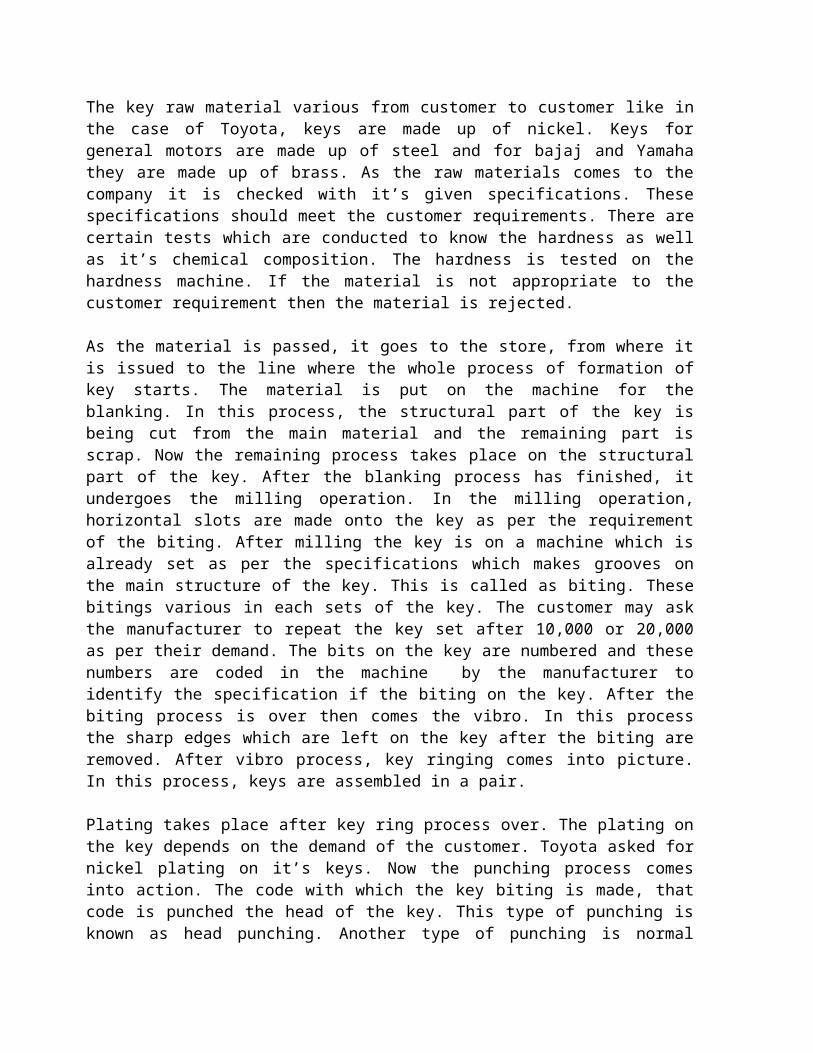
The key raw material various from customer to customer like in the case of Toyota, keys are made up of nickel. Keys for general motors are made up of steel and for bajaj and Yamaha they are made up of brass. As the raw materials comes to the company it is checked with it’s given specifications. These specifications should meet the customer requirements. There are certain tests which are conducted to know the hardness as well as it’s chemical composition. The hardness is tested on the hardness machine. If the material is not appropriate to the customer requirement then the material is rejected.
As the material is passed, it goes to the store, from where it is issued to the line where the whole process of formation of key starts. The material is put on the machine for the blanking. In this process, the structural part of the key is being cut from the main material and the remaining part is scrap. Now the remaining process takes place on the structural part of the key. After the blanking process has finished, it undergoes the milling operation. In the milling operation, horizontal slots are made onto the key as per the requirement of the biting. After milling the key is on a machine which is already set as per the specifications which makes grooves on the main structure of the key. This is called as biting. These bitings various in each sets of the key. The customer may ask the manufacturer to repeat the key set after 10,000 or 20,000 as per their demand. The bits on the key are numbered and these numbers are coded in the machine by the manufacturer to identify the specification if the biting on the key. After the biting process is over then comes the vibro. In this process the sharp edges which are left on the key after the biting are removed. After vibro process, key ringing comes into picture. In this process, keys are assembled in a pair.
Plating takes place after key ring process over. The plating on the key depends on the demand of the customer. Toyota asked for nickel plating on it’s keys. Now the punching process comes into action. The code with which the key biting is made, that code is punched the head of the key. This type of punching is known as head punching. Another type of punching is normal punching, in which punching is done on the tag and it is assembled with the key ringing. Tag punching is required because after the molding process takes place, the head punching would not be visible. Tag punching is done so as to avoid misplacement of the keys.
After the punching process comes the molding process. Molding is a process in which liquid plastic is present at high temperature. This high temperature plastic is poured into the desired mould of the customer specification, on which the customer logo is made.

Apart from this there is another process called coining process. In this process we do not require the molding to take place. The upper part of the key is coined that has the customer’s logo as well as good grip.
9.3 STUDY OF PROBLEM SOLVING TECHNIQUES:-
Problems are commonly occurring in all industries. They are the part of an industry. There are many problems that are solved daily in the industries. Some problems are large and some are small. But in industries each and every problem is solved in a specific order. There are different techniques, which are used to solve the problems in industry. Similarly the problems are solved in Minda in a systematic way. The technique used in Minda to solve the problems are “5 PRINCIPLE ANALYSIS” and “WHY-WHY ANALYSIS”
We discuss these two ways to solve the problems completely in the following pages:
5 PRINCIPLE ANALYSIS
The 5 P Analysis is 5 principal claim analysis. In this technique the problem is solved in different stages. Every problem is analyzed in different steps.
The different steps used in “5 P Analysis” are:1) OCCURANCE OF PROBLEM.2) REOCCURANCE OF OCCURANCE PHENOMENON.3) CAUSE INVESTIGATION.4) COUNTER MEASURE.5) COUNTER MEASURE EFFECTIVENESS.
1) OCCURANCE OF PROBLEM:-
This is the first step in the “5P Analysis” theory. The problem may occur on the customer end. Then the customer is complaints to the company. First we analyze the occurrence phenomenon, then occurrence place, date, quality etc. The occurrence of the problem also identify with the help of “5W1H” theory. The meaning of “5W1H” is WHENWHEREWHOWHATWHY

HOW
In “5W1H theory” we analyze that when the problem occurs and where the problem occurs i.e. at the customer end or in the company or at the user end. Then who is responsible for the problem i.e. company or customer. Them what has to be done for the solution of the problem? Then why the action is taking on. Them how the problem is solved. Then we have to find the area and quantity in which the problem is occurred. At last we get a “occurrence phenomenon”.
2. REOCCURANCE OF OCCURANCE PHENOMENON:-
The second step in the “5P Theory” is reoccurrence of occurrence phenomenon. In this step the defected sample from the customer is analyzed and find out that there is actually problem or not. In this phenomenon all the points which are responsible for the occurrence problem are sorted out. Then each and every point is analyzed. This phenomenon is called Trouble Analysis. The trouble analysis is done by observation and measurement phenomenon. Trouble can be finding by observation method or by doing proper measurements. Then we find the change points and area in which trouble is occurred. After the trouble analysis the results are checked with tests and theories. If the results are according to the tests and theories then ok otherwise if the result is not ok i.e. according to the test and theories then we analyze that result again. The main cause from the test results are then analyzed with the help of characteristic diagram or FMEA (failure mode and effect analysis). In FMEA the various factors which are responsible for the failure are sorted out and these points are called possible cause. These possible causes are then analyzed and find out the root cause of the problem.
In this following points are commonly discussed:
1. Trouble occurs in the changed point areas.2. Trouble occurs in the unexpected usage.3. Reconfirm size, material etc. 4. Reconfirm production procedure.5. Reconfirm specification, drawings, design requirement.6. Extent of Quantity.7. Check and find bad condition procedure line.

3. CAUSE INVESTIGATION:-
After the reoccurrence of occurrence phenomenon we find out the root cause of problem. Then we investigate the cause of the problem. The investigation is done with the help of confirm test and “why-why theory”. Why-why theory is commonly used for finding the root cause of problem.
4. COUNTER MEASURE:-
After investigating the cause the next step is to adopt the counter measure of th problem. i.e. the temporary solution of the problem. This step is taken as soon as possible. After finding the temporary treatment then we have to find out the permanent solution of the problem.
5. COUNTER MEASURE EFFECTIVNESS:-
Then we have to analyze that the countermeasure adopted is correct or not. We sort out the points before solving the problem and after solving the problem. Then these points are compared. If the counter measure is found correct then ok otherwise repeat the whole process again.
After the whole process we wait for the feedback from the customer who complaints the problem.

WHY-WHY ANALYSIS
This is another way to solve the problems. This analysis is used to find out the root cause of the problem. In this first we know the problem then we find that why the problem occurs and so on. The example of this analysis is discussed below:
Example of problem solving technique:
As we discussed earlier there is a specific way to solve any problem in the industries. There is another method to solve the problems i.e. WHY-WHY ANALYSIS. In this analysis to find out the root cause of the problem first we start from the failure and then we find why the failure occurs and so on. Therefore this analysis is known as why-why analysis.
Description of problem:
The customer KAWASAKI INDONESIA complaints that the plate hardened was free to rotate as gap observed between cover body and body of the steering lock because of screw was found loose.
Number of people involved:
D.S MEHRA - HEAD DESIGNANIL KUMAR - QAATIN SRIVASTAVA - DESIGN V.K TAYAL - QASUKHPAL SINGH - MATERIALS.
INVESTIGATION PROCESS OR DATA COLLECTION:-
After the customer Kawasaki complaints that the plate hardened was free to rotate as gap observed between cover body and body of the steering lock because of screw was found loose the investigation process starts. This process is also known as data collection process. In this process the data is collected in the following manner:
1. Raw material purchase2. Manufacturing at supplier end.3. Delivery to MCL.4. After that body key no. is punched on the tag and greasing is done.5. Then the assembly of the lock takes place at MCL.

6. Cap is assembled with plate hardened.7. Then assembly of the lock takes place.8. Then final inspection is done while dispatching the material.
After the inspections process the following points are come forward:-
1. There may be interference between the body and cover body which could create gap.2. Tapping depth may be less in the body.3. Threading length of screw may be less. 4. Unscrewing torque less because of less area of thread engagement due to excessive
minor dia of the tapped hole in body.5. The hole may be oversized during die casting due to
i) Over size core pin.ii) Hole deformation during ejection because of bend in core pin.
6. screw sheared off before applying the complete torque due to a) Shear section of screw below specifications.b) Hardness of the screw broken may be higher than spec.c) In balance of screw driver by the operator during tightening. d) Minor dia under size in tapped hole.
7. Screw might go loose because of moderate vibrations in the field as there was oil On threads.
These points came from the investigation process. Then we have to analyze these points to find out the reason of failure.

DATA ANALYSIS:-
1. After analysis we find that no interference observed between body and cover body.2. Tapped hole is through as per drawing and quality by thread plug gauge.3. Screw thread length found as per drawing and ok by thread ring gauge.4. Size of the minor dia of threading in body is observed 3.40/3.46mm.
i) Hole for tapping verified in body before tapping and observed ok as per spec. (3.64/3.66).
ii) Core pin size also verified and observed 3.66~3.72mm.5. a) Sheared section in broken screw checked and observed 2.26~2.32 mm against
specification2.40mm.shearing head strength verified and observed 10~11 Kgf-cm in screw with 2.30 mm dia at shear section unscrewing torque observed as 6.5~7.5 Kgf-cm. b) Head of the broken screw verified and observed 236 Hv (ok as per spec.)c) No. in balancing of screw driver.d) Minor dia of threaded hole found within spec. in 3 holes out of 4 holes.
6. No oil traces observed between threads.
From hear we find that the sheared section was found less than the sheared section given in the test spec.

WHY-WHY ANALYSIS
PROBLEM DESCRIPTION:-
Plate hardened was free to rotate as gap observed between the cover body and body of the steering lock because of screw was found loose.
ANALYSIS
PLATE HARDENED GOT FREE AS SCREW GOT LOOSE WITH MODERATE VIBRATIONS.
WHY
UNSCREWING TORQUE WAS LOW
WHY
TIGHTENING TORQUE WAS LOW
WHY
SCREW SHRARED OFF BEFORE ACHIEVING THE SPECIFIED TIGHTENING TORQUE.
WHY
SCREW SHEAR SECTION WAS LESS THAN SPEC.

ROOT CAUSE:-
SCREW SHEAR SECTION WAS LESS THAN SPEC.
COUNTER MEASURE:-
After finding the root cause we have to find out the countermeasure of the problem. The counter measures are of two types:-
1. IMMEDIATE ACTION.2. PERMANENT CORRECTIVE ACTION.
1. IMMEDIATE ACTION:- Thread sealing adhesive to be used between threads to increase unscrewing torque.
CONFIRMATION:
Anabond applied screw is not opening up to 20 Kgf-cm torque against unscrewing torque of 6.5 Kgf without using adhesive.
PERMANENT CORRECTIVE ACTION:-
1. Unscrewing torque to be increased by increasing the shearing torque with the help of increasing shear section area.
PROJECT ON THE PROBLEM
OF
KEY CAN NOT MOVE FROM OFF TO ON POSITION
DESCRIPTION OF PROBLEM
“KEY CAN NOT MOVE FOM OFF TO ON POSITION”.
PROBLEM BEHAVIOUR:- If key tip is inserted in plate hardened in field failed lock by about 2~3 mm and it is rotated by 180° in either direction and then lock is operated, it starts functioning normally.
DESCRIPTION OF IGNITION SWITCH CUM STEERING LOCK:-
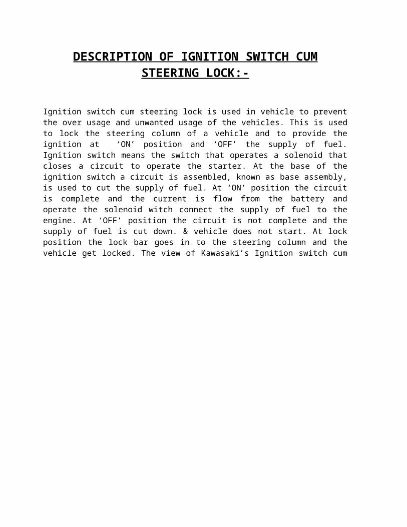
Ignition switch cum steering lock is used in vehicle to prevent the over usage and unwanted usage of the vehicles. This is used to lock the steering column of a vehicle and to provide the ignition at ‘ON’ position and ‘OFF’ the supply of fuel. Ignition switch means the switch that
operates a solenoid that closes a circuit to operate the starter. At the base of the ignition switch a circuit is assembled, known as base assembly, is used to cut the supply of fuel. At ‘ON’ position the circuit is complete and the current is flow from the battery and operate the solenoid witch connect the supply of fuel to the engine. At ‘OFF’ position the circuit is not complete and the supply of fuel is cut down. & vehicle does not start. At lock position the lock bar goes in to the steering column and the vehicle get locked. The view of Kawasaki’s Ignition switch cum steering lock is:-
PARTS OF IGNITION SWITCH CUM STEERING LOCK:-
The main parts of switch are listed below:-

1. BODY.2. ROTOR.3. LOCK PLATES.4. PLATE HARDENED.5. CAP.6. SHUTTER.7. CAM.8. SLIDING PLATE. 9. LOCK BAR.10. BASE.11. KEY.12. MOVING CONTACTS. 13. WIRING HARNESS.14. SPRINGS.15.SCREWS.
HOW THE FAILURE OCCURS:-

The customer “Kawasaki” complaints that the lock cannot move from ‘OFF’ to ‘ON’ position. To solve the problem first we have to find out that ‘How the problem occurs’.To find that how the problem occurs, first we lock the vehicle on left hand side & then on right hand side.
In this the ideal locking position is left hand side. But on right hand side locking position the above problem occurs. This is due to the design of the handle frame assembly.
In left hand side locking position, the frame handle assembly moves in the left direction. A slot is provided in the handle frame assembly for lock bar. Then key of lock turns at lock position and key taken out from switch at lock position, then the lock bar released inside the hole provided in frame for locking. At this position no problem is occurs and key easily move from ‘OFF’ to ‘ON’ position.
In right hand side locking position, the frame of the handle frame assembly turns to the right direction. In this side there is a strip on the frame. In this direction when key turns at locking position & key taken out from switch at lock position & lock bar is not release completely. The lock bar will always press by rib provided in handle frame assembly resulting into reaction force being transmitted upto rotor. Due to this resulting force the rotor remains in pressed state. Due to this the plate hardened, on the upper side of the rotor become free to rotate. This is our main problem. To make problem more clearly the following pictures are attached.
DETAILED DESCRIPTION OF FAILURE:-
Now we know that which type of failure was occurring. Now I give the explanation of the failure. When the handle is turned in right hand side, the lock bar does not release completely.
Due to this the rotor does not rotate completely to lock position (i.e. rotor stopper stuck below the body stopper as shown in figure)
BODY STOPPER
ROTOR STOPPER
BODY STOPPER DID NOT RELEASE 'ROTOR STOPPER‘AT 'LOCK' POSITION
Now we know that the stopper of body does not release the stoppers of rotor. Due to this the rotor is not release completely and gap is created between plate hardened and rotor.
Due to this the plate hardened above the rotor is free to move as there is no engagement between plate hardened and rotor. At this position if the key is inserted only in plate hardened and is rotated at 180° then there is mismatching between plate hardened and rotor slots due to difference in the size of plate hardened pins & rotor holes. The view of this on pro-e is shown in figure:

PINS OF PLATE HARDENED NOT ALLOWING ROTOR TO COME OUT. ( BIG PIN ALIGNING WITH SMALL HOLE)
PLATE HARDENED
BODY ROTOR
KEY
From the figure it is clear that the big pin is aligning with the small hole and the small pin is aligning with the big hole. Due to this the rotor remains stuck below the plate hardened even when the operator operates the lock normally & doesn’t release completely at “OFF” Position.
Stopper in body interfering with the rotor
Now when the lock is turned from “OFF” to “ON” position then the stopper in the body doesn’t allow the rotor to rotate as shown in picture above. But in normal condition if the plate hardened was not rotated by 180° (ie the Pins & holes were aligned ) then rotor stopper would have cleared the stopper in body & there would have been no problem in rotating it from “OFF” to “ON” position as explained in picture below

Rotated by about 180°, in either direction, it starts functioning normally.
NG POSITION OF PLATE HARDENED
OK POSITION OF PLATE HARDENED
This is the detailed description of the problem. Now we have analyzed the problem. The analysis of the problem is done in various ways. But we adopt “WHY-WHY ANALYSIS” as it is very suitable for the solution of any problem. The analysis process is described on the next page.

ANALYSIS OF PROBLEM:-
This is a very serious problem complaint by the Japanese customer “KAWASAKI”. As we discussed earlier the problems are solved in industry in a systematic way. So we adopt “WHY-WHY ANALYSIS” to solve this problem. In this analysis a problem is analyzed in different steps. In this type of analysis, first we wrights the main problem, then we wrights the cause of this problem and so on. In this way we find out the root cause of the problem.
The analysis to solve the problem is explained below:
WHY-WHY ANALYSIS
KEY MOVEMENT JAM FROM ‘OFF’ TO ‘ON’ POSITION.
ROTOR STOPPER GETTING RESTRICTED BY BODY STOPPER (at top) FOR ROTATION.
ROTOR DID NOT COME OUT COMPLETELY AT ‘OFF’ POSITION.
PIN OF PLATE HARDENED NOT ALLOWING ROTOR TO COME OUT (BIG PIN ALIGINING WITH SMALL HOLE)
PLATE HARDENED ROTATED BY 180° ANGLE.
PLATE HARDNED WAS NOT ENGAGED WITH ROTOR AT ‘LOCK’.
ROTOR DID NOT JUMP OUT RESULTING INTO PLATE HARDENED WAS FREE TO ROTATE.
BODY STOPPER (at bottom) DID NOT RELEASE ‘ROTOR STOPPER’ AT ‘LOCK’POSITION

ROOT CAUSE OF PROBLEM:-
The root cause obtained from “WHY-WHY ANALYSIS” was:-
1. LOCKING OF STEERING LOCK TO KEEP THE HANDLE IN OPPOSITE
DIRECTION (i.e. RIGHT HAND SIDE). IN SUCH CONDITION LOCK BAR WILL ALWAYS BE PRESSED BY RIB PROVIDED IN HANDLE FRAME ASSEMBLY RESULTING INTO REACTION FORCE BEING TRANSMITTED UPTO ROTOR.
2. IN SUFFICIENT ANGULAR CLEARANCE BETWEEN STOPPER OF ROTOR & BODY TO ACCOMMODATE ABOVE REACTION FORCE.

COUNTER MEASURE:-
Now we find the root cause of the failure and we have to find out the solution of the problem. To find the counter measure of the problem, all the members that are involved in solving the problem, discussed the problem thoroughly. After the discussion, the following countermeasures come forward.
1. CLEARANCE TO BE INCREASED BETWEEN ROTOR AND BODY STOPPER.2. CHAMFER TO BE PROVIDED AT THE EDGES OF BODY STOPPER.3. BODY TOOL TO BE MODIFIED.4. VALIDATION OF LOCK AFTER MODIFICATION, FOR THE FAILURE MODE.5. MODIFIED BODY TO BE USED FOR PRODUCTION.6. ROTOR DESIGN TO BE MODIFIED i.e. SMALL HOLE IN THE ROTOR MAD
EQUAL TO THE BIGGER HOLE SO THAT EVEN AFTER 180° ROTATION OF PLATE HARDENED, LOCK REMAIN FUNSTIONABLE.
These are the counter measure of the failure. Now we have to implement these counter measures.
First step is to increase the clearance between the body stoppers and the rotor stoppers. This is done to avoid the interference between the rotor and body stoppers. By measurement we find that the interference is about 0.28mm. Therefore to avoid it we apply the cut on both sides of the body stoppers. After doing this the interference is completely removed and the rotor is released completely. After providing the cut, chamfer is also provided on the body stoppers. The chamfer is provided on body cuts due to the reason that if there is still some interference, then the rotor slips from the chamfer provided. This helps in the easy operation of the lock. The figure shows both the before and after views:- .

1. INSUFFICIENT CLEARANCE BETWEEN BODY & ROTOR STOPPER
BEFOREBEFORE AFTERAFTER
COUNTERMEASURE: COUNTERMEASURE:
1. CLEARANCE INCREASED BETWEEN BODY & ROTOR STOPPER (WHITE COLOR)
2. CHAMFER PROVIDED ON THE EDGES OF BODY STOPPERS (RED COLOR)
The picture shows the two views, first view shows the interference between the rotor and body stoppers. In second view cut and chamfer is provided.
After the application of these steps, body tool is modified. This is required because the shape of the body changes. Then the lock is checked in the quality lab. Here the lock is operated upto 50,000 cycles. The testing of the lock is necessary because the shape of the body changes. Then the modified body is used for production.
Then we modified the design of rotor is changed i.e. small hole in the rotor made equal to the bigger hole. This is done because even if the plate hardened is rotated through 180° the lock remains functional. The view is given in figure:-

1. BOTH HOLES DIFFERENT SIZE
BEFOREBEFORE
1. SMALL HOLE IN ROTOR MADE EQUAL TO BIGGER HOLE SO THAT EVEN AFTER 180° ROTATION OF PLATE HARDENED, LOCK REMAIN FUNCTIONAL.
AFTERAFTER
COUNTERMEASURECOUNTERMEASURE