Embed Size (px)
Citation preview

SAFETY FIRST! As with all electrical equipment, only qualified, expert personnel should perform maintenance and installation. Comply with all applicable local and national codes and laws that regulate the installation and operation of equipment and read manuals thoroughly. Use only installation manuals and not this sales brochure for installation procedures. It is up to the installer to determine product suitability for a given application.
© 2020 Franklin Electric Co., Inc. Product improvement is a continual process. Pricing and specifications subject to change without notice. Marketing materials should not be relied upon for technical specification. Cerus, Mira, Orion, Titan, Franklin Electric and associated logos are trademarks of Franklin Electric Co., Inc. All sales subject to Franklin Electric Terms and Conditions.
3
ISS with SmartStart™ ........................................................................................................... 4Ordering & Sizing Information ...................................................................................................................................................................................5Specifications ..............................................................................................................................................................................................................6Wiring Diagram ...........................................................................................................................................................................................................7Dimensions ..................................................................................................................................................................................................................8
ISS - Industrial Start/Stop .................................................................................................... 9Specifications ............................................................................................................................................................................................................ 10Ordering & Sizing Information .................................................................................................................................................................................. 11Dimensions ................................................................................................................................................................................................................ 13Wiring Diagrams ....................................................................................................................................................................................................... 15
IXP - Explosion Proof Starter ............................................................................................... 18Ordering & Sizing Information ................................................................................................................................................................................. 19Wiring Diagram ........................................................................................................................................................................................................ 20Specifications ............................................................................................................................................................................................................ 21Dimensions ................................................................................................................................................................................................................ 21
IMS-RV - Intelligent Motor Soft-Starter ................................................................................. 23Ordering & Sizing Information .................................................................................................................................................................................24Wiring Diagram .........................................................................................................................................................................................................25Specifications ............................................................................................................................................................................................................26Dimensions ................................................................................................................................................................................................................27
ISS-RV - Industrial Soft-Starter ............................................................................................ 28Ordering & Sizing Information .................................................................................................................................................................................29Specifications ............................................................................................................................................................................................................30Wiring Diagrams ....................................................................................................................................................................................................... 31Dimensions ................................................................................................................................................................................................................ 31
DPX - Duplex Alternating Controller......................................................................................32Ordering & Sizing Information ................................................................................................................................................................................ 32Wiring Diagram ......................................................................................................................................................................................................... 33Dimensions ................................................................................................................................................................................................................ 33
Enclosed Manual Motor Starter .............................................................................................34Ordering & Sizing Information .................................................................................................................................................................................34MMS Accessories ........................................................................................................................................................................................................35Dimensions ................................................................................................................................................................................................................35
Enclosed Reversing Starter ..................................................................................................36Ordering & Sizing Information ................................................................................................................................................................................ 36Wiring Diagram .........................................................................................................................................................................................................37
franklin-controls.com.For the most up-to-date product information, visit
INDUSTRIAL SMART STARTERS CATALOG
4
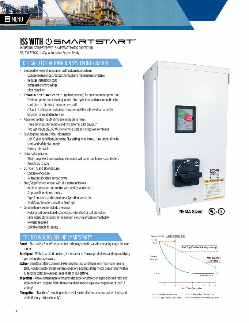
• Designed for ease of integration with automation systems · Comprehensive inputs/outputs for building management systems · Reduces installation costs · Increased energy savings · High reliability
• (patent pending) for superior motor protection · Electronic protection including locked rotor, cycle fault and maximum time to
start (due to mis-sized motor or overload) · FLA out of calibration indication--ensures installer sets overload correctly
based on calculated motor size• Advanced control inputs eliminate interposing relays
· Three dry inputs for remote and two external pilot devices* · Two wet inputs (12-250VAC) for remote start and shutdown command
• Fault logging retains critical information · Last 10 start conditions, including FLA setting, max inrush, run current, time to
start, and safety start mode. · Factory retrievable
• Universal application · Wide-range electronic overload eliminates call backs due to mis-sized heaters · Accepts up to 575V
• UL Type 1, 4, and 3R enclosures · Lockable enclosure · 3R features lockable keypad cover
• Start/Stop/Remote keypad with LED status indicators · Intuitive operation and control with start (manual run), · Stop, and Remote run modes · Type 4 enclosed starters feature a 3 position switch for · Start/Stop/Remote, and a Run Pilot Light
• Combination versions include disconnect · Motor circuit protection disconnect provides short circuit protection · High interrupting ratings for maximum electrical system compatibility · No fuses required · Lockable handle for safety
INDUSTRIAL START/STOP WITH SMARTSTART MOTOR PROTECTION3Ø, 200~575VAC, 1–40A, Automation System Ready
ISS WITH
NEMA Sized
®
®
DESIGNED FOR AUTOMATION SYSTEM INTEGRATION
Smart - Start safely. SmartStart patented technology predicts a safe operating range for your motor.
Intelligent - With SmartStart enabled, if the starter isn’t in range, it alarms and trips notifying you before damage occurs.
Active - SmartStart detects harmful extended starting conditions with maximum time to start. Monitors motor inrush current conditions and trips if the motor doesn’t start within 10 seconds (class 10 overload) regardless of FLA setting.
Ingenious - Active current monitoring provides superior protection against locked rotor and stall conditions, tripping faster than a standard inverse trip curve, regardless of the FLA setting!
Thoughtful - “Blackbox” recording feature retains critical information on last ten faults and starts (factory retrievable only).
THE TECHNOLOGY BEHIND SMARTSTART™
1 2 3 4 5 6 7 8 9 10
FLA
Current (amps)
FLA6-10x
Motor Inrush
Start Time (seconds)
Standard Start Curve
Locked Rotor Trip
Stall Trip (Disabled during startup)
Max Time to Start Trip
Locked Rotor Current
Typical Motor Stall Current
Motor Never Reaches FLA
Standard Motor Starting Current
5
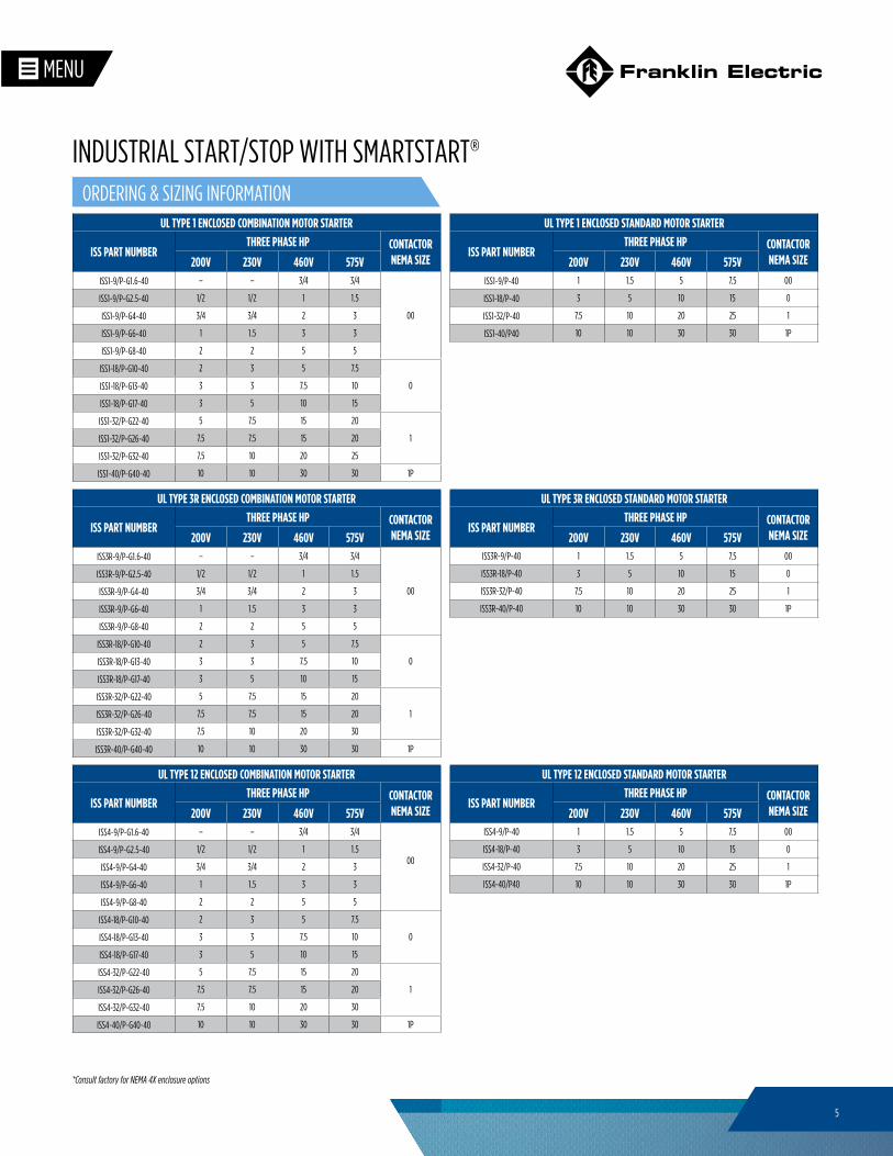
UL TYPE 1 ENCLOSED STANDARD MOTOR STARTER
ISS PART NUMBERTHREE PHASE HP CONTACTOR
NEMA SIZE200V 230V 460V 575VISS1-9/P-40 1 1.5 5 7.5 00
ISS1-18/P-40 3 5 10 15 0
ISS1-32/P-40 7.5 10 20 25 1
ISS1-40/P40 10 10 30 30 1P
UL TYPE 12 ENCLOSED STANDARD MOTOR STARTER
ISS PART NUMBERTHREE PHASE HP CONTACTOR
NEMA SIZE200V 230V 460V 575VISS4-9/P-40 1 1.5 5 7.5 00
ISS4-18/P-40 3 5 10 15 0
ISS4-32/P-40 7.5 10 20 25 1
ISS4-40/P40 10 10 30 30 1P
UL TYPE 12 ENCLOSED COMBINATION MOTOR STARTER
ISS PART NUMBERTHREE PHASE HP CONTACTOR
NEMA SIZE200V 230V 460V 575VISS4-9/P-G1.6-40 – – 3/4 3/4
00ISS4-9/P-G2.5-40 1/2 1/2 1 1.5
ISS4-9/P-G4-40 3/4 3/4 2 3
ISS4-9/P-G6-40 1 1.5 3 3
ISS4-9/P-G8-40 2 2 5 5
ISS4-18/P-G10-40 2 3 5 7.5
0ISS4-18/P-G13-40 3 3 7.5 10
ISS4-18/P-G17-40 3 5 10 15
ISS4-32/P-G22-40 5 7.5 15 20
1ISS4-32/P-G26-40 7.5 7.5 15 20
ISS4-32/P-G32-40 7.5 10 20 30
ISS4-40/P-G40-40 10 10 30 30 1P
UL TYPE 3R ENCLOSED STANDARD MOTOR STARTER
ISS PART NUMBERTHREE PHASE HP CONTACTOR
NEMA SIZE200V 230V 460V 575VISS3R-9/P-40 1 1.5 5 7.5 00
ISS3R-18/P-40 3 5 10 15 0
ISS3R-32/P-40 7.5 10 20 25 1
ISS3R-40/P-40 10 10 30 30 1P
UL TYPE 3R ENCLOSED COMBINATION MOTOR STARTER
ISS PART NUMBERTHREE PHASE HP CONTACTOR
NEMA SIZE200V 230V 460V 575VISS3R-9/P-G1.6-40 – – 3/4 3/4
00
ISS3R-9/P-G2.5-40 1/2 1/2 1 1.5
ISS3R-9/P-G4-40 3/4 3/4 2 3
ISS3R-9/P-G6-40 1 1.5 3 3
ISS3R-9/P-G8-40 2 2 5 5
ISS3R-18/P-G10-40 2 3 5 7.5
0ISS3R-18/P-G13-40 3 3 7.5 10
ISS3R-18/P-G17-40 3 5 10 15
ISS3R-32/P-G22-40 5 7.5 15 20
1ISS3R-32/P-G26-40 7.5 7.5 15 20
ISS3R-32/P-G32-40 7.5 10 20 30
ISS3R-40/P-G40-40 10 10 30 30 1P
*Consult factory for NEMA 4X enclosure options
UL TYPE 1 ENCLOSED COMBINATION MOTOR STARTER
ISS PART NUMBERTHREE PHASE HP CONTACTOR
NEMA SIZE200V 230V 460V 575VISS1-9/P-G1.6-40 – – 3/4 3/4
00
ISS1-9/P-G2.5-40 1/2 1/2 1 1.5
ISS1-9/P-G4-40 3/4 3/4 2 3
ISS1-9/P-G6-40 1 1.5 3 3
ISS1-9/P-G8-40 2 2 5 5
ISS1-18/P-G10-40 2 3 5 7.5
0ISS1-18/P-G13-40 3 3 7.5 10
ISS1-18/P-G17-40 3 5 10 15
ISS1-32/P-G22-40 5 7.5 15 20
1ISS1-32/P-G26-40 7.5 7.5 15 20
ISS1-32/P-G32-40 7.5 10 20 25
ISS1-40/P-G40-40 10 10 30 30 1P
ORDERING & SIZING INFORMATION
INDUSTRIAL START/STOP WITH SMARTSTART®
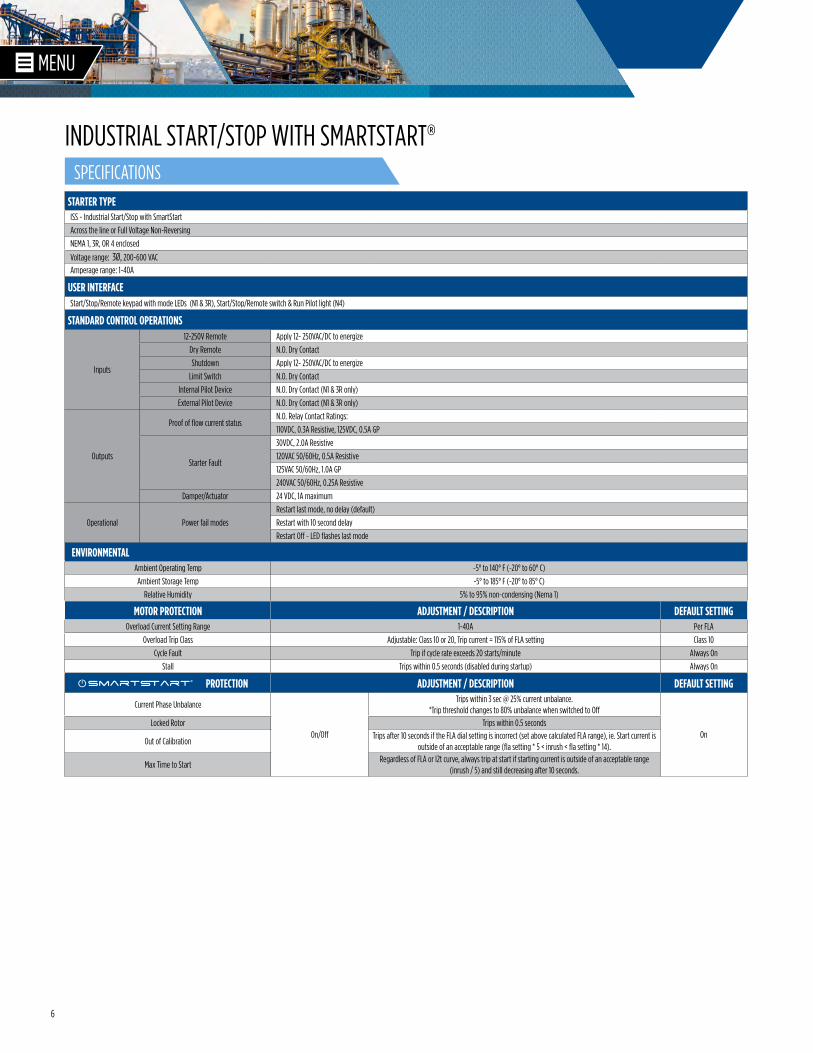
6
STARTER TYPEISS - Industrial Start/Stop with SmartStart
Across the line or Full Voltage Non-Reversing
NEMA 1, 3R, OR 4 enclosed
Voltage range: 3Ø, 200-600 VACAmperage range: 1-40A
USER INTERFACEStart/Stop/Remote keypad with mode LEDs (N1 & 3R), Start/Stop/Remote switch & Run Pilot light (N4)
STANDARD CONTROL OPERATIONS
Inputs
12-250V Remote Apply 12- 250VAC/DC to energize
Dry Remote N.O. Dry Contact
Shutdown Apply 12- 250VAC/DC to energize
Limit Switch N.O. Dry Contact
Internal Pilot Device N.O. Dry Contact (N1 & 3R only)
External Pilot Device N.O. Dry Contact (N1 & 3R only)
Outputs
Proof of flow current statusN.O. Relay Contact Ratings:
110VDC, 0.3A Resistive, 125VDC, 0.5A GP
Starter Fault
30VDC, 2.0A Resistive
120VAC 50/60Hz, 0.5A Resistive
125VAC 50/60Hz, 1.0A GP
240VAC 50/60Hz, 0.25A Resistive
Damper/Actuator 24 VDC, 1A maximum
Operational Power fail modes
Restart last mode, no delay (default)
Restart with 10 second delay
Restart Off - LED flashes last mode
ENVIRONMENTALAmbient Operating Temp -5° to 140° F (-20° to 60° C)
Ambient Storage Temp -5° to 185° F (-20° to 85° C)
Relative Humidity 5% to 95% non-condensing (Nema 1)
MOTOR PROTECTION ADJUSTMENT / DESCRIPTION DEFAULT SETTINGOverload Current Setting Range 1-40A Per FLA
Overload Trip Class Adjustable: Class 10 or 20, Trip current = 115% of FLA setting Class 10
Cycle Fault Trip if cycle rate exceeds 20 starts/minute Always On
Stall Trips within 0.5 seconds (disabled during startup) Always On
PROTECTION ADJUSTMENT / DESCRIPTION DEFAULT SETTING
Current Phase Unbalance
On/Off
Trips within 3 sec @ 25% current unbalance. *Trip threshold changes to 80% unbalance when switched to Off
OnLocked Rotor Trips within 0.5 seconds
Out of CalibrationTrips after 10 seconds if the FLA dial setting is incorrect (set above calculated FLA range), ie. Start current is
outside of an acceptable range (fla setting * 5 < inrush < fla setting * 14).
Max Time to StartRegardless of FLA or I2t curve, always trip at start if starting current is outside of an acceptable range
(inrush / 5) and still decreasing after 10 seconds.
Smart�art®
INDUSTRIAL START/STOP WITH SMARTSTART®SPECIFICATIONS
7
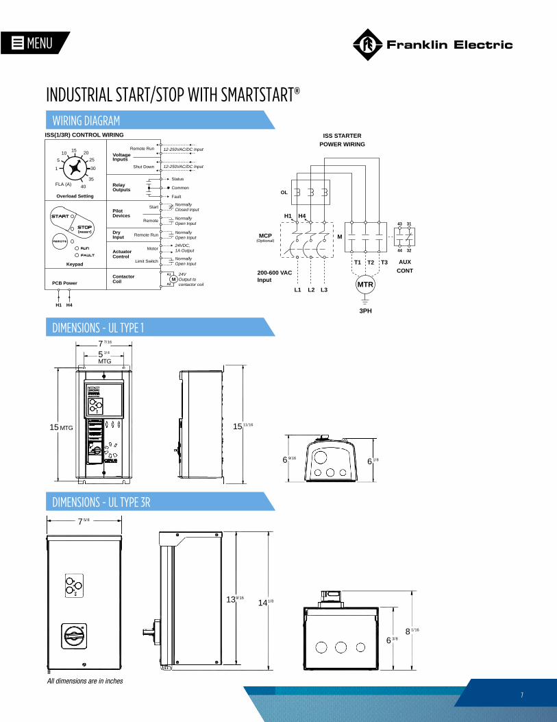
15 11/16
5
15
1/4
7 7/16
6 9/16 6 1/8
MTG
MTG
H1 H4
L3L1 L2MTR
T1 T3 AUXCONT
M
T2
OL
3PH
43
44
31
32
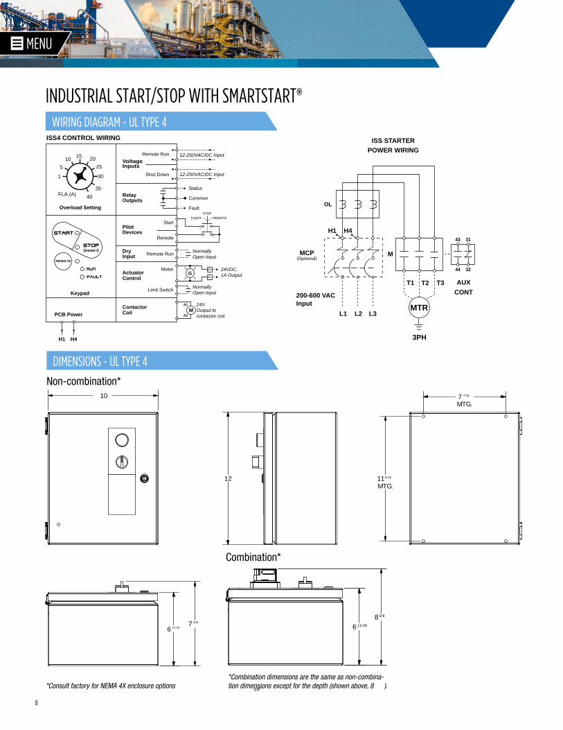
ISS STARTERPOWER WIRING
ISS(1/3R) CONTROL WIRING
1
FLA (A)
5
1015 20
25
30
35
40
PCB Power
H1 H4
Keypad
Overload Setting
MCP(Optional)
SCHM-ISS-V3
ActuatorControl
DryInput
RelayOutputs
VoltageInputs
ContactorCoil
A1
A2M
Motor
Limit Switch Normally Open Input
24VDC, 1A Output
Common
Fault
Status
Shut Down 12-250VAC/DC Input
Remote Run
Remote
Start
Remote Run 12-250VAC/DC Input
Normally Open Input
Normally Open Input
Normally Closed Input
24V Output to contactor coil
Pilot Devices
200-600 VACInput
H1 H4
L3L1 L2MTR
T1 T3 AUXCONT
M
T2
OL
3PH
43
44
31
32
ISS STARTERPOWER WIRING
ISS(1/3R) CONTROL WIRING
1
FLA (A)
5
1015 20
25
30
35
40
PCB Power
H1 H4
Keypad
Overload Setting
MCP(Optional)
SCHM-ISS-V3
ActuatorControl
DryInput
RelayOutputs
VoltageInputs
ContactorCoil
A1
A2M
Motor
Limit Switch Normally Open Input
24VDC, 1A Output
Common
Fault
Status
Shut Down 12-250VAC/DC Input
Remote Run
Remote
Start
Remote Run 12-250VAC/DC Input
Normally Open Input
Normally Open Input
Normally Closed Input
24V Output to contactor coil
Pilot Devices
200-600 VACInput
WIRING DIAGRAM
139/16
141/8
6 3/88 1/16
7 5/8
All dimensions are in inches
INDUSTRIAL START/STOP WITH SMARTSTART®
DIMENSIONS - UL TYPE 1
DIMENSIONS - UL TYPE 3R
8
H1 H4
L3L1 L2MTR
T1 T3 AUXCONT
M
T2
OL
3PH
43
44
31
32
ISS STARTERPOWER WIRING
ISS4 CONTROL WIRING
1
FLA (A)
5
1015 20
25
30
35
40
PCB Power
H1 H4
Keypad
Overload Setting
MCP(Optional)
ActuatorControl
DryInput
RelayOutputs
VoltageInputs
ContactorCoil
A1
A2M
Motor
Limit Switch Normally Open Input
24VDC, 1A Output
Common
Fault
Status
Shut Down 12-250VAC/DC Input
Remote Run
Remote
Start
Remote Run 12-250VAC/DC Input
Normally Open Input
24V Output to contactor coil
Pilot Devices
X
X
STARTSTOP
REMOTE
200-600 VACInput
GA-
A+
H1 H4
L3L1 L2MTR
T1 T3 AUXCONT
M
T2
OL
3PH
43
44
31
32
ISS STARTERPOWER WIRING
ISS4 CONTROL WIRING
1
FLA (A)
5
1015 20
25
30
35
40
PCB Power
H1 H4
Keypad
Overload Setting
MCP(Optional)
ActuatorControl
DryInput
RelayOutputs
VoltageInputs
ContactorCoil
A1
A2M
Motor
Limit Switch Normally Open Input
24VDC, 1A Output
Common
Fault
Status
Shut Down 12-250VAC/DC Input
Remote Run
Remote
Start
Remote Run 12-250VAC/DC Input
Normally Open Input
24V Output to contactor coil
Pilot Devices
X
X
STARTSTOP
REMOTE
200-600 VACInput
GA-
A+
683/8
11/16
10
67
7MTG.
11
5/8
11/16
5/16
7/16
MTG.12
*Combination dimensions are the same as non-combina-tion dimensions except for the depth (shown above, 8 ).
Combination*
Non-combination*
*Consult factory for NEMA 4X enclosure options 5/8”
WIRING DIAGRAM - UL TYPE 4
DIMENSIONS - UL TYPE 4
INDUSTRIAL START/STOP WITH SMARTSTART®
9
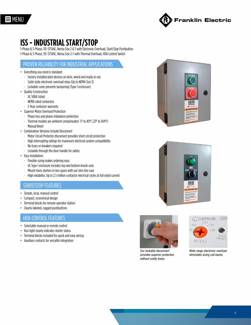
• Everything you need is standard · Factory installed pilot devices on door, wired and ready to use · Solid-state electronic overload relay (Up to NEMA Size 3) · Lockable cover prevents tampering (Type 1 enclosure)
• Quality Construction · UL 508A Listed · NEMA rated contactors · 5-Year contactor warranty
• Superior Motor Overload Protection · Phase loss and phase imbalance protection · Thermal models are ambient compensated -5º to 40ºC (23º to 104ºF) · Manual Reset
• Combination Versions Include Disconnect · Motor Circuit Protector disconnect provides short circuit protection · High interrupting ratings for maximum electrical system compatibility · No fuses or breakers required · Lockable through the door handle for safety
• Easy Installation · Flexible sizing makes ordering easy · UL Type 1 enclosure includes top and bottom knock-outs · Mount more starters in less space with our slim line case · High reliability: Up to 2.5 million contactor electrical cycles at full rated current
Wide range electronic overload eliminates sizing call backs.
Our lockable disconnect provides superior protection without costly fuses.
1-Phase & 3-Phase, 115~575VAC, Nema Size 2 & 3 with Electronic Overload, Start/Stop Pushbutton1-Phase & 3-Phase, 115~575VAC, Nema Size 2-7 with Thermal Overload, HOA Control Switch
ISS - INDUSTRIAL START/STOP
PROVEN RELIABILITY FOR INDUSTRIAL APPLICATIONS
START/STOP FEATURES
HOA CONTROL FEATURES
• Simple, local, manual control• Compact, economical design• Terminal blocks for remote operator station• Clearly labeled, rugged pushbuttons
• Selectable manual or remote control• Run light clearly indicates starter status• Terminal blocks included for quick and easy wiring• Auxiliary contacts for versatile integration
10
START/STOP PUSHBUTTON MODEL SPECIFICATIONS
STARTER TYPEISS - Industrial Start/Stop with Electronic Overload
Across the line or Full Voltage Non-Reversing, Standard or Combination
UL Type 1, 3R, or 4/12
Range: NEMA size 2 and 3 enclosed
USER INTERFACEStart/Stop Pushbuttons or Hand/Off/Auto [HOA] Switch
STANDARD CONTROL OPERATIONS Start/Stop — 3-Wire Terminal Block Provision for remote Start/Stop
HOA - Auto-run inputN.O. dry contact. When closed, the starter will be commanded to run when
in auto mode.
MECHANICAL Enclosure types UL Type 1, 3R or 4/12
ENVIRONMENTALAmbient Operating Temp -5° to 140°F (-20° to 60°C)
Ambient Storage Temp -5° to 185°F (-20° to 85°C)
Relative Humidity 5% to 95% non-condensing (NEMA 1)
MOTOR PROTECTION ADJUSTMENT/DESCRIPTIONOverload Type Electronic; I2t Thermal Trip Curve
Trip Class 1- 30
Reset Manual
Phase Unbalanced Trip within 3 seconds @ 70% unbalance
Phase Loss Trip within 3 seconds
Stall Trip within 3 seconds @ 170% FLA
HOA CONTROL MODEL SPECIFICATIONS
STARTER TYPEISS - Industrial Starter with Thermal Overload
Across the line or Full Voltage Non-Reversing, Standard or Combination
UL Type 1, 3R, or 4/12
Range: NEMA size 2 – 7
USER INTERFACEStart / Stop Pushbuttons or Hand/Off/Auto [HOA] Switch
STANDARD CONTROL OPERATIONS Start/Stop — 3-Wire Terminal block provision for remote Start/Stop
HOA - Auto-run inputN.O. dry contact. When closed, the starter will be
commanded to run when in auto mode.
MECHANICAL Enclosure types UL Type 1, 3R or 4/12
ENVIRONMENTALAmbient Compensated
Operating Temp23° to 104°F (-5° to 40°C)
Ambient Storage Temp -5° to 185°F (-20° to 85°C)
Relative Humidity 5% to 95% non-condensing (NEMA 1)
MOTOR PROTECTION ADJUSTMENT/DESCRIPTIONOverload Type Thermal bi-metallic
Trip Class Class 10
Reset Manual
Phase Loss Differential overload protection
SPECIFICATIONS
ISS - INDUSTRIAL START/STOP
11
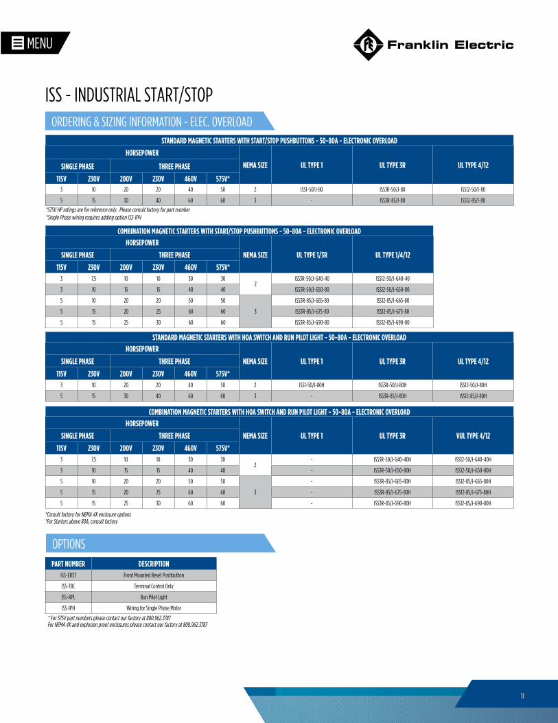
STANDARD MAGNETIC STARTERS WITH START/STOP PUSHBUTTONS - 50-80A - ELECTRONIC OVERLOAD
HORSEPOWER
NEMA SIZE UL TYPE 1 UL TYPE 3R UL TYPE 4/12SINGLE PHASE THREE PHASE
115V 230V 200V 230V 460V 575V*3 10 20 20 40 50 2 ISS1-50/J-80 ISS3R-50/J-80 ISS12-50/J-80
5 15 30 40 60 60 3 - ISS3R-85/J-80 ISS12-85/J-80
COMBINATION MAGNETIC STARTERS WITH START/STOP PUSHBUTTONS - 50-80A - ELECTRONIC OVERLOADHORSEPOWER
NEMA SIZE UL TYPE 1/3R UL TYPE 1/4/12SINGLE PHASE THREE PHASE
115V 230V 200V 230V 460V 575V*3 7.5 10 10 30 30
2ISS3R-50/J-G40-40 ISS12-50/J-G40-40
3 10 15 15 40 40 ISS3R-50/J-G50-80 ISS12-50/J-G50-80
5 10 20 20 50 50
3
ISS3R-85/J-G65-80 ISS12-85/J-G65-80
5 15 20 25 60 60 ISS3R-85/J-G75-80 ISS12-85/J-G75-80
5 15 25 30 60 60 ISS3R-85/J-G90-80 ISS12-85/J-G90-80
PART NUMBER DESCRIPTIONISS-ERST Front Mounted Reset Pushbutton
ISS-TBC Terminal Control Only
ISS-RPL Run Pilot Light
ISS-1PH Wiring for Single Phase Motor
* For 575V part numbers please contact our factory at 800.962.3787For NEMA 4X and explosion proof enclosures please contact our factory at 800.962.3787
STANDARD MAGNETIC STARTERS WITH HOA SWITCH AND RUN PILOT LIGHT - 50-80A - ELECTRONIC OVERLOADHORSEPOWER
NEMA SIZE UL TYPE 1 UL TYPE 3R UL TYPE 4/12SINGLE PHASE THREE PHASE
115V 230V 200V 230V 460V 575V*3 10 20 20 40 50 2 ISS1-50/J-80H ISS3R-50/J-80H ISS12-50/J-80H
5 15 30 40 60 60 3 - ISS3R-85/J-80H ISS12-85/J-80H
COMBINATION MAGNETIC STARTERS WITH HOA SWITCH AND RUN PILOT LIGHT - 50-80A - ELECTRONIC OVERLOADHORSEPOWER
NEMA SIZE UL TYPE 1 UL TYPE 3R VUL TYPE 4/12SINGLE PHASE THREE PHASE
115V 230V 200V 230V 460V 575V*3 7.5 10 10 30 30
2- ISS3R-50/J-G40-40H ISS12-50/J-G40-40H
3 10 15 15 40 40 - ISS3R-50/J-G50-80H ISS12-50/J-G50-80H
5 10 20 20 50 50
3
- ISS3R-85/J-G65-80H ISS12-85/J-G65-80H
5 15 20 25 60 60 - ISS3R-85/J-G75-80H ISS12-85/J-G75-80H
5 15 25 30 60 60 - ISS3R-85/J-G90-80H ISS12-85/J-G90-80H
*Consult factory for NEMA 4X enclosure options*For Starters above 80A, consult factory
*575V HP ratings are for reference only. Please consult factory for part number*Single Phase wiring requires adding option ISS-1PH
ORDERING & SIZING INFORMATION - ELEC. OVERLOAD
OPTIONS
ISS - INDUSTRIAL START/STOP
12
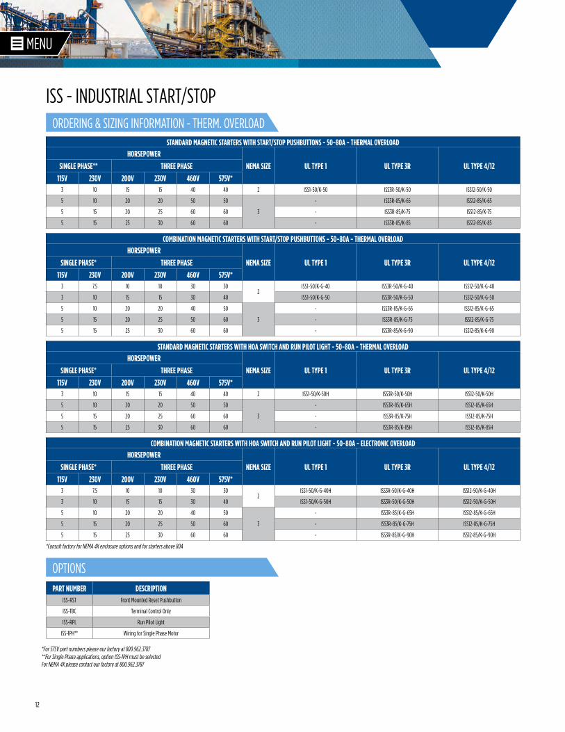
COMBINATION MAGNETIC STARTERS WITH START/STOP PUSHBUTTONS - 50-80A - THERMAL OVERLOADHORSEPOWER
NEMA SIZE UL TYPE 1 UL TYPE 3R UL TYPE 4/12SINGLE PHASE* THREE PHASE
115V 230V 200V 230V 460V 575V*3 7.5 10 10 30 30
2ISS1-50/K-G-40 ISS3R-50/K-G-40 ISS12-50/K-G-40
3 10 15 15 30 40 ISS1-50/K-G-50 ISS3R-50/K-G-50 ISS12-50/K-G-50
5 10 20 20 40 50
3
- ISS3R-85/K-G-65 ISS12-85/K-G-65
5 15 20 25 50 60 - ISS3R-85/K-G-75 ISS12-85/K-G-75
5 15 25 30 60 60 - ISS3R-85/K-G-90 ISS12-85/K-G-90
STANDARD MAGNETIC STARTERS WITH START/STOP PUSHBUTTONS - 50-80A - THERMAL OVERLOADHORSEPOWER
NEMA SIZE UL TYPE 1 UL TYPE 3R UL TYPE 4/12SINGLE PHASE** THREE PHASE
115V 230V 200V 230V 460V 575V*3 10 15 15 40 40 2 ISS1-50/K-50 ISS3R-50/K-50 ISS12-50/K-50
5 10 20 20 50 50
3
- ISS3R-85/K-65 ISS12-85/K-65
5 15 20 25 60 60 - ISS3R-85/K-75 ISS12-85/K-75
5 15 25 30 60 60 - ISS3R-85/K-85 ISS12-85/K-85
PART NUMBER DESCRIPTIONISS-RST Front Mounted Reset Pushbutton
ISS-TBC Terminal Control Only
ISS-RPL Run Pilot Light
ISS-1PH** Wiring for Single Phase Motor
*For 575V part numbers please our factory at 800.962.3787**For Single Phase applications, option ISS-1PH must be selected
COMBINATION MAGNETIC STARTERS WITH HOA SWITCH AND RUN PILOT LIGHT - 50-80A - ELECTRONIC OVERLOADHORSEPOWER
NEMA SIZE UL TYPE 1 UL TYPE 3R UL TYPE 4/12SINGLE PHASE* THREE PHASE
115V 230V 200V 230V 460V 575V*3 7.5 10 10 30 30
2ISS1-50/K-G-40H ISS3R-50/K-G-40H ISS12-50/K-G-40H
3 10 15 15 30 40 ISS1-50/K-G-50H ISS3R-50/K-G-50H ISS12-50/K-G-50H
5 10 20 20 40 50
3
- ISS3R-85/K-G-65H ISS12-85/K-G-65H
5 15 20 25 50 60 - ISS3R-85/K-G-75H ISS12-85/K-G-75H
5 15 25 30 60 60 - ISS3R-85/K-G-90H ISS12-85/K-G-90H
STANDARD MAGNETIC STARTERS WITH HOA SWITCH AND RUN PILOT LIGHT - 50-80A - THERMAL OVERLOADHORSEPOWER
NEMA SIZE UL TYPE 1 UL TYPE 3R UL TYPE 4/12SINGLE PHASE* THREE PHASE
115V 230V 200V 230V 460V 575V*3 10 15 15 40 40 2 ISS1-50/K-50H ISS3R-50/K-50H ISS12-50/K-50H
5 10 20 20 50 50
3
- ISS3R-85/K-65H ISS12-85/K-65H
5 15 20 25 60 60 - ISS3R-85/K-75H ISS12-85/K-75H
5 15 25 30 60 60 - ISS3R-85/K-85H ISS12-85/K-85H
*Consult factory for NEMA 4X enclosure options and for starters above 80A
For NEMA 4X please contact our factory at 800.962.3787
ORDERING & SIZING INFORMATION - THERM. OVERLOAD
OPTIONS
ISS - INDUSTRIAL START/STOP
13
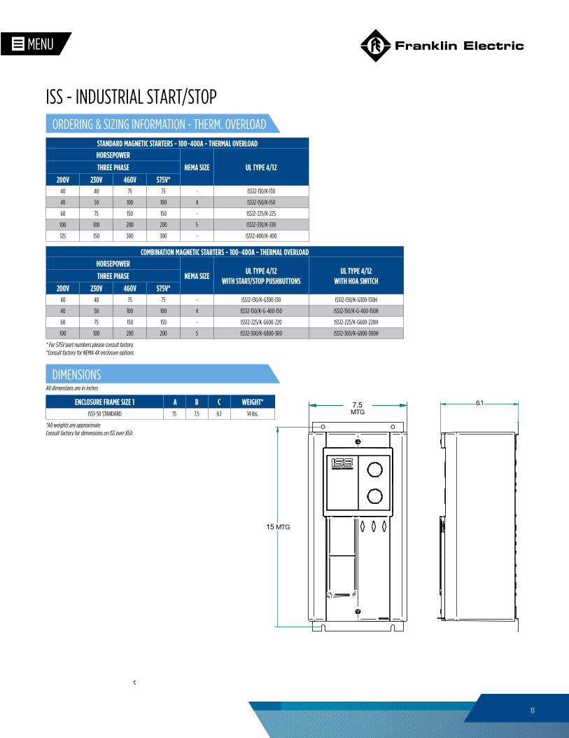
STANDARD MAGNETIC STARTERS - 100~400A - THERMAL OVERLOADHORSEPOWER
NEMA SIZE UL TYPE 4/12 THREE PHASE
200V 230V 460V 575V*40 40 75 75 - ISS12-130/K-130
40 50 100 100 4 ISS12-150/K-150
60 75 150 150 - ISS12-225/K-225
100 100 200 200 5 ISS12-330/K-330
125 150 300 300 - ISS12-400/K-400
COMBINATION MAGNETIC STARTERS - 100~400A - THERMAL OVERLOADHORSEPOWER
NEMA SIZEUL TYPE 4/12
WITH START/STOP PUSHBUTTONSUL TYPE 4/12
WITH HOA SWITCH THREE PHASE
200V 230V 460V 575V*40 40 75 75 - ISS12-130/K-G300-130 ISS12-130/K-G300-130H
40 50 100 100 4 ISS12-150/K-G-400-150 ISS12-150/K-G-400-150H
60 75 150 150 - ISS12-225/K-G600-220 ISS12-225/K-G600-220H
100 100 200 200 5 ISS12-300/K-G800-300 ISS12-300/K-G800-300H
* For 575V part numbers please consult factory.
ENCLOSURE FRAME SIZE 1 A B C WEIGHT*ISS1-50 STANDARD 15 7.5 6.1 14 lbs.
15 MTG
MTG7.5 6.1
*All weights are approximate
All dimensions are in inches
Consult factory for dimensions on ISS over 85A
*Consult factory for NEMA 4X enclosure options
ORDERING & SIZING INFORMATION - THERM. OVERLOAD
DIMENSIONS
ISS - INDUSTRIAL START/STOP
14
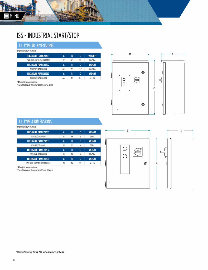
ENCLOSURE FRAME SIZE 1 A B C WEIGHT*ISS3R-50/J ~ ISS3R-85/J STANDARD 16.3 12.5 7.7 25-45 lbs.
ENCLOSURE FRAME SIZE 2 A B C WEIGHTISS3R-50/J COMBINATION 22.3 15.5 9.7 25-45 lbs.
ENCLOSURE FRAME SIZE 3 A B C WEIGHTISS3R-85/J COMBINATION 32.3 15.5 9.7 50+ lbs.
ENCLOSURE FRAME SIZE 2 A B C WEIGHTISS12-50/J STANDARD 12 10 6 35 lbs.
ENCLOSURE FRAME SIZE 4 A B C WEIGHTISS12-50/K COMBINATION 16 14 8 25-45 lbs.
ENCLOSURE FRAME SIZE 3 A B C WEIGHTISS12-85/J STANDARD 14 12 6 35 lbs.
A
B C
ENCLOSURE FRAME SIZE 4 A B C WEIGHTISS12-50/J ~ ISS12-85/J COMBINATION 20 16 10 50+ lbs.
* All weights are approximate
* All weights are approximate* Consult factory for dimensions on ISS over 85 amps.
* Consult factory for dimensions on ISS over 85 amps.
*Consult factory for NEMA 4X enclosure options
A
B C
A
B C
UL TYPE 4 DIMENSIONS
UL TYPE 3R DIMENSIONS
ISS - INDUSTRIAL START/STOP
All dimensions are in inches
All dimensions are in inches
15
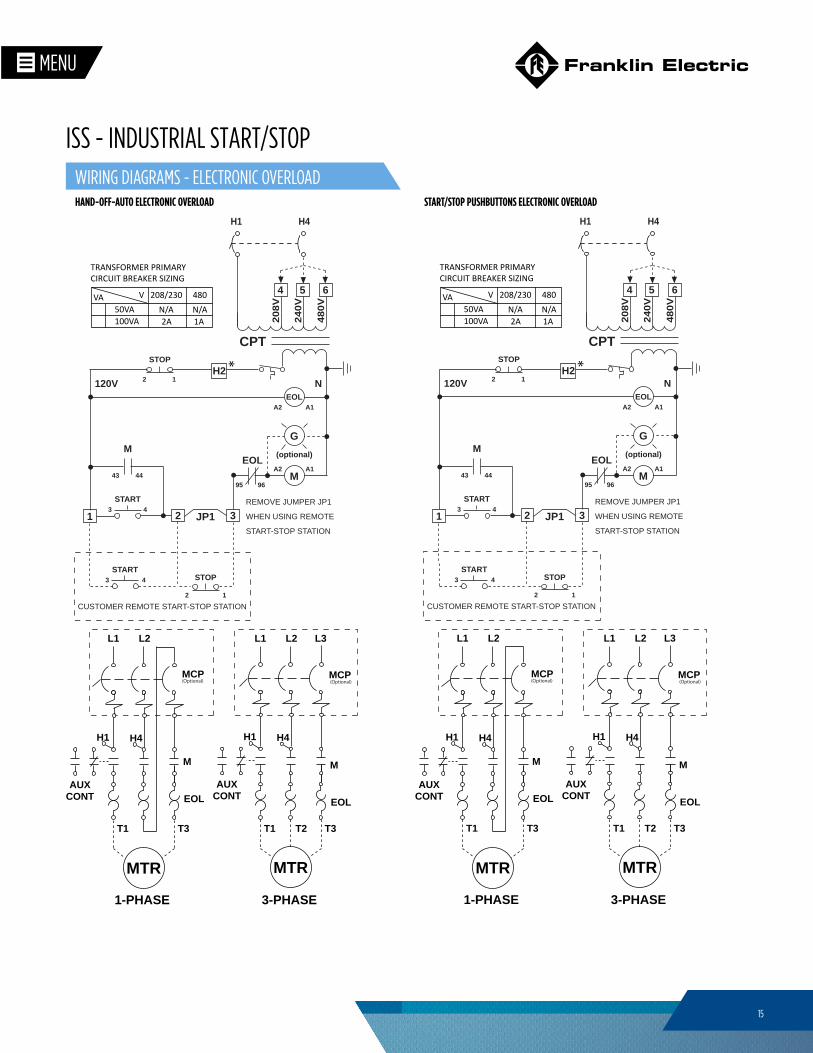
HAND-OFF-AUTO ELECTRONIC OVERLOAD START/STOP PUSHBUTTONS ELECTRONIC OVERLOAD
REMOVE JUMPER JP1
WHEN USING REMOTE
START-STOP STATION
CPT
120V
143
START
JP12 3
M
(optional)
43START
12
STOP
12
STOP
G
43 44
M
A2 A1
N
CUSTOMER REMOTE START-STOP STATION
A2 A1EOL
EOL
95 96
H1 H4
208V
240V
480V
654
SCHM-ISS/EOL-V1
TRANSFORMER PRIMARYCIRCUIT BREAKER SIZING
VA 208/230 480V50VA100VA 2A 1A
N/A N/A
3-PHASE1-PHASE
M
AUXCONT
H1 H4
L1 L2
T1 T3
MTR
MCP
EOL
M
AUXCONT
H1 H4
L1 L2
T1 T3
MTR
MCP
EOL
L3
T2
*H2 Terminal does not apply for Type 1 enclosed configurations
H2 *
(Optional) (Optional)
WIRING DIAGRAMS - ELECTRONIC OVERLOAD
ISS - INDUSTRIAL START/STOP
16
MA2 A1
14
MCP
13
G
CPT
120V N
H1 H4
208V
240V
480V
543
SCHM-SAS120/C-V1
TRANSFORMER PRIMARYCIRCUIT BREAKER SIZING
VA 208/230 480V50VA100VA 2A 1A
N/A N/A
2
OH A
X00
00X
X00
1START
M
AUXCONT
H1 H4
L1 L2
T1 T3
MTR
M
AUXCONT
H1 H4
L1 L2 L3
T1 T2 T3
MTR
MCP MCP
THREE PHASE SINGLE PHASE
H0 *
*H0 Terminal does not apply for Type 1 enclosed configurations
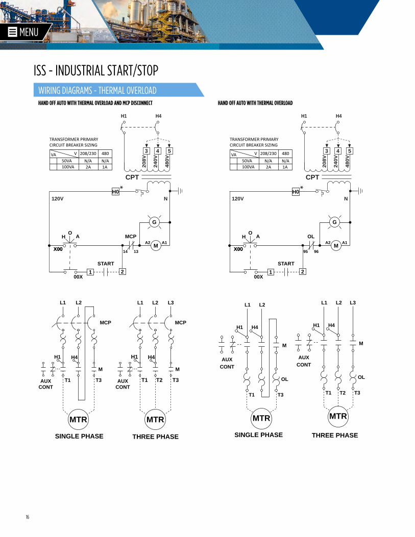
HAND OFF AUTO WITH THERMAL OVERLOAD AND MCP DISCONNECT HAND OFF AUTO WITH THERMAL OVERLOAD
MA2 A1
95
OL
96
G
CPT
120V N
H1 H4
208V
240V
480V
543
SCHM-SAS120/S-V1
TRANSFORMER PRIMARYCIRCUIT BREAKER SIZING
VA 208/230 480V50VA100VA 2A 1A
N/A N/A
2
OH A
X00
00X
X00
1START
H0 *
*H0 Terminal does not apply for Type 1 enclosed configurations
THREE PHASE SINGLE PHASE
L3
OL
MTR
AUXCONT
T1 T3
L1 L2
H1 H4
M
OL
MTR
AUXCONT
T1 T3
L1 L2
H1 H4
M
T2
WIRING DIAGRAMS - THERMAL OVERLOAD
ISS - INDUSTRIAL START/STOP
17
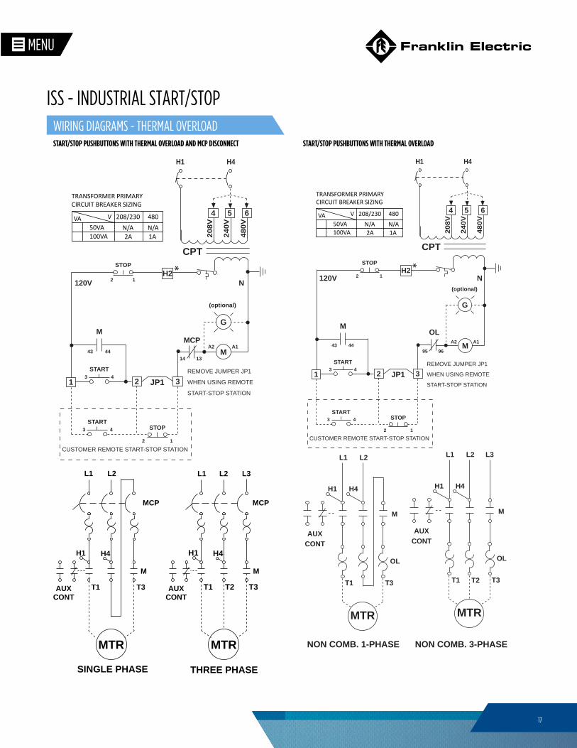
START/STOP PUSHBUTTONS WITH THERMAL OVERLOAD AND MCP DISCONNECT START/STOP PUSHBUTTONS WITH THERMAL OVERLOAD
REMOVE JUMPER JP1
WHEN USING REMOTE
START-STOP STATION
CPT
120V
143
START
JP12 3
M
(optional)
43START
12
STOP
12
STOP
G
43 44
M
A2 A1
N
CUSTOMER REMOTE START-STOP STATION
MCP
14 13
H1 H4
208V
240V
480V
654
SCHM-ISS/TOL/C-V1
TRANSFORMER PRIMARYCIRCUIT BREAKER SIZING
VA 208/230 480V50VA100VA 2A 1A
N/A N/A
*H2 Terminal does not apply for Type 1 enclosed configurations
H2 *
M
AUXCONT
H1 H4
L1 L2
T1 T3
MTR
M
AUXCONT
H1 H4
L1 L2 L3
T1 T2 T3
MTR
MCP MCP
THREE PHASE SINGLE PHASESCHM-ISS/TOL/S-V1
REMOVE JUMPER JP1
WHEN USING REMOTE
START-STOP STATION
120V
95
OL
96
143
START
JP12 3
M
(optional)
43START
12
STOP
12
STOP
G
43 44
M
A2 A1
N
CUSTOMER REMOTE START-STOP STATION
NON COMB. 3-PHASE
L3
NON COMB. 1-PHASE
OL
MTR
AUXCONT
T1 T3
L1 L2
H1 H4
M
OL
MTR
AUXCONT
T1 T3
L1 L2
H1 H4
M
T2
CPT
H1 H4
208V
240V
480V
654
TRANSFORMER PRIMARYCIRCUIT BREAKER SIZING
VA 208/230 480V50VA100VA 2A 1A
N/A N/A
*H2 Terminal does not apply for Type 1 enclosed configurations
H2 *
WIRING DIAGRAMS - THERMAL OVERLOAD
ISS - INDUSTRIAL START/STOP
18
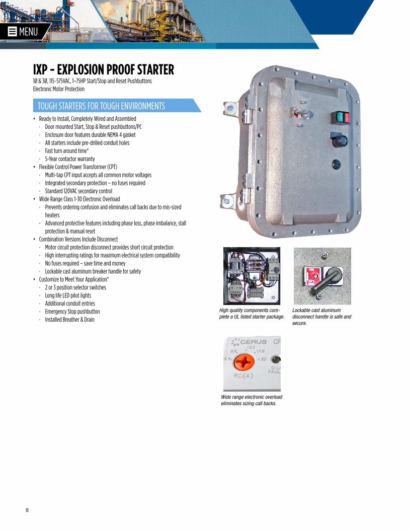
1Ø & 3Ø, 115~575VAC, 1–75HP Start/Stop and Reset PushbuttonsElectronic Motor Protection
• Ready to Install, Completely Wired and Assembled · Door mounted Start, Stop & Reset pushbuttons/PC · Enclosure door features durable NEMA 4 gasket · All starters include pre-drilled conduit holes · Fast turn around time* · 5-Year contactor warranty
• Flexible Control Power Transformer (CPT) · Multi-tap CPT input accepts all common motor voltages · Integrated secondary protection – no fuses required · Standard 120VAC secondary control
• Wide Range Class 1-30 Electronic Overload · Prevents ordering confusion and eliminates call backs due to mis-sized
heaters · Advanced protective features including phase loss, phase imbalance, stall
protection & manual reset • Combination Versions Include Disconnect
· Motor circuit protection disconnect provides short circuit protection · High interrupting ratings for maximum electrical system compatibility · No fuses required – save time and money · Lockable cast aluminum breaker handle for safety
• Customize to Meet Your Application* · 2 or 3 position selector switches · Long life LED pilot lights · Additional conduit entries · Emergency Stop pushbutton · Installed Breather & Drain
High quality components com-plete a UL listed starter package.
Lockable cast aluminum disconnect handle is safe and secure.
Wide range electronic overload eliminates sizing call backs.
TOUGH STARTERS FOR TOUGH ENVIRONMENTS
IXP - EXPLOSION PROOF STARTER
19
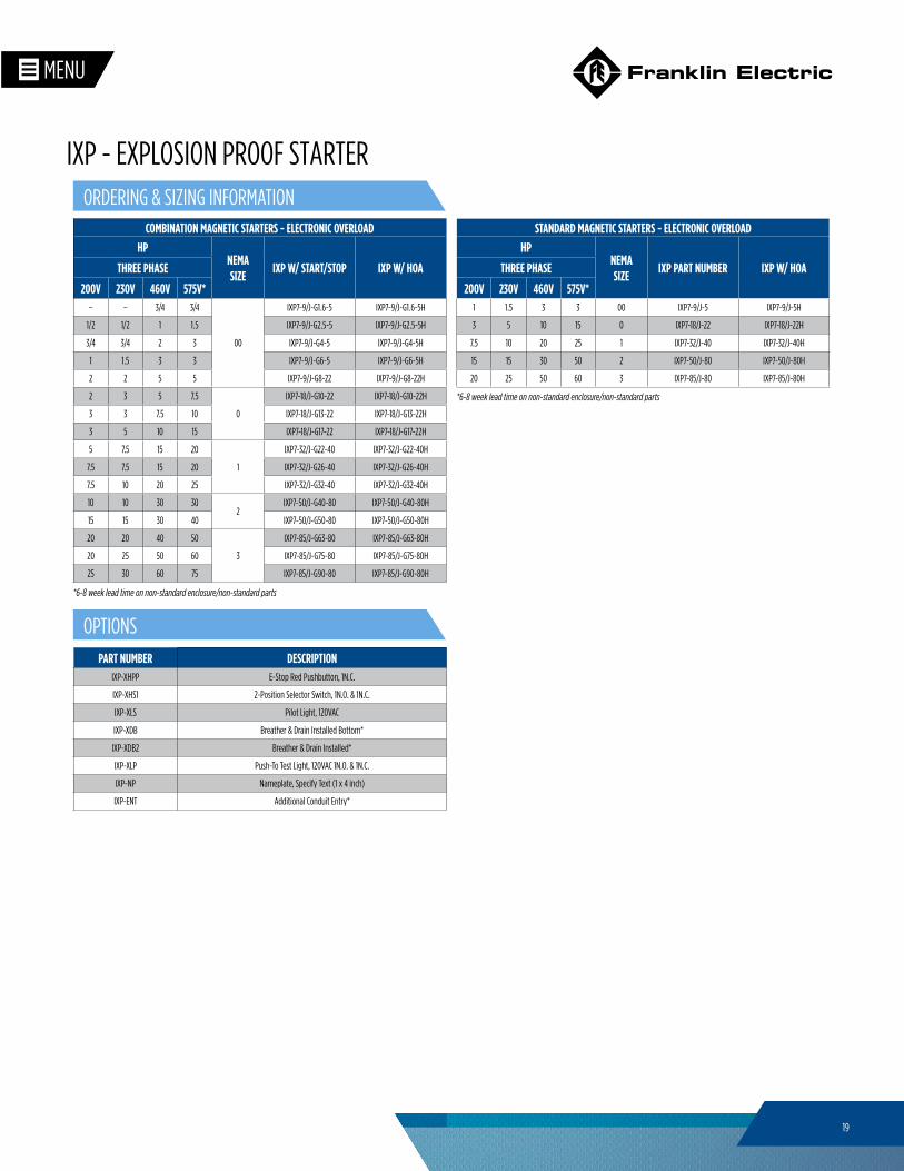
*6-8 week lead time on non-standard enclosure/non-standard parts
*6-8 week lead time on non-standard enclosure/non-standard parts
COMBINATION MAGNETIC STARTERS - ELECTRONIC OVERLOAD HP
NEMASIZE
IXP W/ START/STOP IXP W/ HOATHREE PHASE
200V 230V 460V 575V*– – 3/4 3/4
00
IXP7-9/J-G1.6-5 IXP7-9/J-G1.6-5H
1/2 1/2 1 1.5 IXP7-9/J-G2.5-5 IXP7-9/J-G2.5-5H
3/4 3/4 2 3 IXP7-9/J-G4-5 IXP7-9/J-G4-5H
1 1.5 3 3 IXP7-9/J-G6-5 IXP7-9/J-G6-5H
2 2 5 5 IXP7-9/J-G8-22 IXP7-9/J-G8-22H
2 3 5 7.5
0
IXP7-18/J-G10-22 IXP7-18/J-G10-22H
3 3 7.5 10 IXP7-18/J-G13-22 IXP7-18/J-G13-22H
3 5 10 15 IXP7-18/J-G17-22 IXP7-18/J-G17-22H
5 7.5 15 20
1
IXP7-32/J-G22-40 IXP7-32/J-G22-40H
7.5 7.5 15 20 IXP7-32/J-G26-40 IXP7-32/J-G26-40H
7.5 10 20 25 IXP7-32/J-G32-40 IXP7-32/J-G32-40H
10 10 30 302
IXP7-50/J-G40-80 IXP7-50/J-G40-80H
15 15 30 40 IXP7-50/J-G50-80 IXP7-50/J-G50-80H
20 20 40 50
3
IXP7-85/J-G63-80 IXP7-85/J-G63-80H
20 25 50 60 IXP7-85/J-G75-80 IXP7-85/J-G75-80H
25 30 60 75 IXP7-85/J-G90-80 IXP7-85/J-G90-80H
ORDERING & SIZING INFORMATION
OPTIONS
IXP - EXPLOSION PROOF STARTER
STANDARD MAGNETIC STARTERS - ELECTRONIC OVERLOAD HP
NEMASIZE
IXP PART NUMBER IXP W/ HOATHREE PHASE
200V 230V 460V 575V*1 1.5 3 3 00 IXP7-9/J-5 IXP7-9/J-5H
3 5 10 15 0 IXP7-18/J-22 IXP7-18/J-22H
7.5 10 20 25 1 IXP7-32/J-40 IXP7-32/J-40H
15 15 30 50 2 IXP7-50/J-80 IXP7-50/J-80H
20 25 50 60 3 IXP7-85/J-80 IXP7-85/J-80H
PART NUMBER DESCRIPTIONIXP-XHPP E-Stop Red Pushbutton, 1N.C.
IXP-XHS1 2-Position Selector Switch, 1N.O. & 1N.C.
IXP-XLS Pilot Light, 120VAC
IXP-XDB Breather & Drain Installed Bottom*
IXP-XDB2 Breather & Drain Installed*
IXP-XLP Push-To Test Light, 120VAC 1N.O. & 1N.C.
IXP-NP Nameplate, Specify Text (1 x 4 inch)
IXP-ENT Additional Conduit Entry*
20
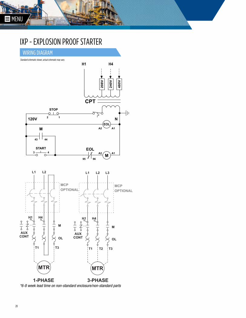
Standard schematic shown, actual schematic may vary.
*6-8 week lead time on non-standard enclosure/non-standard parts
WIRING DIAGRAM
IXP - EXPLOSION PROOF STARTER
21
838
1738
1338
1058
MTG.
1234
MTG.
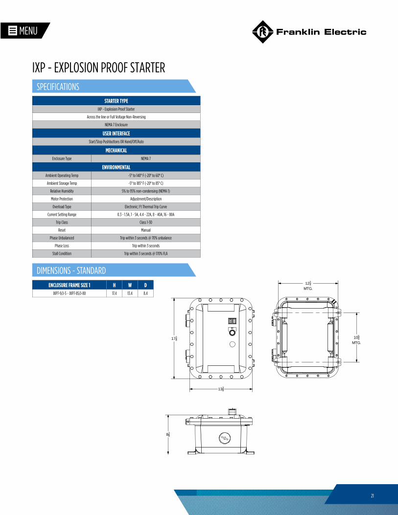
DIMENSIONS - STANDARD
SPECIFICATIONS
IXP - EXPLOSION PROOF STARTER
STARTER TYPEIXP - Explosion Proof Starter
Across the line or Full Voltage Non-Reversing
NEMA 7 Enclosure
USER INTERFACEStart/Stop Pushbuttons OR Hand/Off/Auto
MECHANICAL Enclosure Type NEMA 7
ENVIRONMENTAL Ambient Operating Temp -5° to 140° F (-20° to 60° C)
Ambient Storage Temp -5° to 185° F (-20° to 85° C)
Relative Humidity 5% to 95% non-condensing (NEMA 1)
Motor Protection Adjustment/Description
Overload Type Electronic; I2t Thermal Trip Curve
Current Setting Range 0.3 - 1.5A, 1 - 5A, 4.4 - 22A, 8 - 40A, 16 - 80A
Trip Class Class 1-30
Reset Manual
Phase Unbalanced Trip within 3 seconds @ 70% unbalance
Phase Loss Trip within 3 seconds
Stall Condition Trip within 3 seconds @ 170% FLA
ENCLOSURE FRAME SIZE 1 H W DIXP7-9/J-5 ~ IXP7-85/J-80 17.4 13.4 8.4
22
2214
1614
1034
1418 MTG.
1534 MTG.
2214
1614
1034
1418 MTG.
1534 MTG.
A173
8
1338
1058
MTG.
13MTG.
812
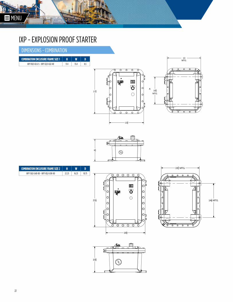
DIMENSIONS - COMBINATION
IXP - EXPLOSION PROOF STARTER
COMBINATION ENCLOSURE FRAME SIZE 1 H W DIXP7-18/J-G1.6-5 ~ IXP7-32/J-G32-40 17.4 13.4 8.5
COMBINATION ENCLOSURE FRAME SIZE 2 H W DIXP7-50/J-G40-80 ~ IXP7-85/J-G90-80 22.25 16.25 10.75
23
• Integrated electronic motor protection · Our most advanced motor protection · Wide range class 5-30 electronic overload · Advanced protective features include over/under voltage/power, phase loss/unbalance,
stalled/locked rotor, cycle fault and UL 1053 ground fault• Soft start features
· Adjustable current limit, initial voltage, start/stop time · Coast to stop · Torque boost · SCR over-temperature detection · Shorted SCR detection · Across-the-line start for emergency situations
• Built-in power monitoring, fault logging and communications · Last 15 fault types are recorded (overload, voltage/current loss unbalance, etc.) · Fault counter: stores how many times each fault type has occurred (Up to 255) · Logs changes to parameter settings (e.g. overload, OV/UV) · All power condition values are displayed · Built-in RS-485 for Modbus RTU communication
• Industrial grade construction · Door mounted HOA switch · UL/NEMA Type 3R outdoor rating (4, 4X Available) · Multi-tap transformer accommodates common voltages; no fuses required · 120V control power for field devices (optional 24V) · NEMA rated contactor, 2.5 Million electrical cycles at full rated current
• Programmable control options · Auto-restart · Backspin delay · On/Off delay settings · Minimum run time based on last input · 12-120V auto run input terminal for remote start/stop · Dry contact input terminal for remote start/stop · Analog input for (selectable) 0-10V, 4-20mA, 10k Thermistor, viewable as a Modbus point
• Optional circuit breaker disconnect. · UL 489 circuit breaker provides branch and short circuit protection · No fuses required · Lockable handle for safety
3Ø, 200~460VAC, 2–250HP, Advanced Electronic OverloadIntegrated Contactor Bypass
THE WORLD'S MOST INTELLIGENT SOFT-STARTER
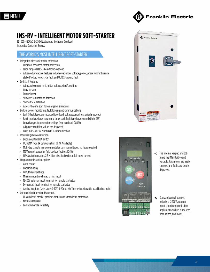
IMS-RV - INTELLIGENT MOTOR SOFT-STARTER
The internal keypad and LCD make the IMS intuitive and versatile. Parameters are easily changed and faults are clearly displayed.
Standard control features include a 12-120V auto run input, shutdown terminal for applications such as a low level float switch, and more.
<
<
24
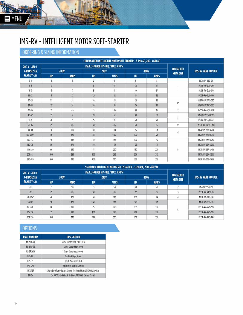
COMBINATION INTELLIGENT MOTOR SOFT STARTER - 3-PHASE, 200–460VAC
200 V - 460 V 3-PHASE SFA RANGE** (A)
MAX. 3-PHASE HP (UL) / MAX. AMPSCONTACTOR NEMA SIZE
IMS-RV PART NUMBER200V 230V 460VHP AMPS HP AMPS HP AMPS
6~8 2 8 2 8 5 8
1
IMS3R-RV-S1/J-G15
8~11 3 11 3 11 7.5 11 IMS3R-RV-S1/J-G20
11~17 3 17 5 17 10 17 IMS3R-RV-S1/J-G30
16~22 5 22 7.5 22 15 22 IMS3R-RV-S1/J-G40
20~28 7.5 28 10 28 20 281P
IMS3R-RV-S1P/J-G50
24~34 10 34 10 34 25 34 IMS3R-RV-S1P/J-G60
32~45 10 45 15 45 30 45 2 IMS3R-RV-S2/J-G80
40~57 15 57 20 57 40 573
IMS3R-RV-S3/J-G100
50~71 20 71 25 71 50 71 IMS3R-RV-S3/J-G125
60~85 25 85 30 85 60 85 3P IMS3R-RV-S3P/J-G150
80~114 30 114 40 114 75 1144
IMS3R-RV-S4/J-G200
100~DPV* 40 120 50 130 100 124 IMS3R-RV-S4/J-G250
100~142 40 142 50 142 100 142
5
IMS3R-RV-S5/J-G250
120~170 50 170 50 171 125 171 IMS3R-RV-S5/J-G300
160~220 60 220 75 220 150 220 IMS3R-RV-S5/J-G400
201~285 100 285 100 285 200 285 IMS3R-RV-S5/J-G500
240~320 100 330 100 330 250 330 IMS3R-RV-S5/J-G600
PART NUMBER DESCRIPTIONIMS-SRG240 Surge Suppressor, 200/230 V
IMS-SRG480 Surge Suppressor, 460 V
IMS-SRG600 Surge Suppressor, 600 V
IMS-RPL Run Pilot Light, Green
IMS-FPL Fault Pilot Light, Red
IMS-SPB Start Push-Button Control
IMS-STSP Start/Stop Push-Button Control (In Lieu of Hand/Off/Auto Switch)
IMS-24 24 VAC Control Circuit (In Lieu of 120 VAC Control Circuit)
STANDARD INTELLIGENT MOTOR SOFT STARTER - 3-PHASE, 200–460VAC
200 V - 460 V 3-PHASE SFA RANGE** (A)
MAX. 3-PHASE HP (UL) / MAX. AMPSCONTACTOR NEMA SIZE
IMS-RV PART NUMBER200V 230V 460VHP AMPS HP AMPS HP AMPS
1~50 15 50 15 50 30 50 2 IMS3R-RV-S2/J-50
1~85 25 85 30 85 77 85 3 IMS3R-RV-S3P/J-85
50~DPV* 40 120 50 130 100 124 4 IMS3R-RV-S4/J-130
50~170 50 170 60 170 125 170
5
IMS3R-RV-S5/J-170
151~220 60 220 75 220 150 220 IMS3R-RV-S5/J-220
176~270 75 270 100 270 200 270 IMS3R-RV-S5/J-270
201~330 100 330 125 330 250 330 IMS3R-RV-S5/J-330
OPTIONS
ORDERING & SIZING INFORMATION
IMS-RV - INTELLIGENT MOTOR SOFT-STARTER
25
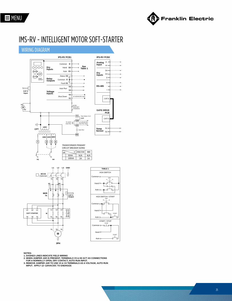
GND
H1 H4
L1 L2
T1 T3
L3
T2
13
14
21
22
A B C
CAT 5OLOutput
T3 T1T2
M
3PH
L3 L1L2
T1 T3T2
SOFT STARTER M
L1 L3L2
T1 T3T2
A1
A2M
IPS-RV PCB1
Common
Hand
Auto
Common
Fault
Status
Shut Down
Auto Run
12-120VAC/DC Input
CAT 5 Input
TRANSFORMER PRIMARYCIRCUIT BREAKER SIZING
VA 200/230 480V50VA100VA 2A 1A
N/A N/A
120V
240V 480V208V
CPT
H1 H4
To V3/V4 Auto Run
See Table 1
HOA SWITCH
HOA SWITCH / START
START / STOP
TABLE 1
Common
Hand
Auto
OFF H A
X
X
X
OFF H A
X
XCommon
Hand
Auto
START
Common
Hand
Auto
START
STOP
NOTES:1. DASHED LINES INDICATE FIELD WIRING2. WHEN JUMPER JAR IS PRESENT, TERMINALS V3 & H2 ACT AS CONNECTIONS FOR A NORMALLY OPEN, DRY CONTACT, AUTO RUN INPUT. 3. REMOVE JUMPER JAR TO USE V3 & V4 TERMINALS AS A VOLTAGE, AUTO RUN INPUT. APPLY 12~120VAC/DC TO ENERGIZE
RS-485+
S
-
AnalogInput
A-
A+
DryInputs
D
D4
D3
CAT-5
GATE DRIVE PCB
TempSensor
S1
S2
CAT-5
IPS-RV PCB2
V1
V2
V3
V4
O1
O2
O
D1
D
D2
Auto Run
12-120VAC/DC Auto Run Input
JAR
H2
V3
V4
N
Voltage Inputs
Relay Outputs
Dry Inputs
*See Notes 2 & 3
MCCB(Optional)
JDS-DO NOT REMOVE
WIRING DIAGRAM
IMS-RV - INTELLIGENT MOTOR SOFT-STARTER
26
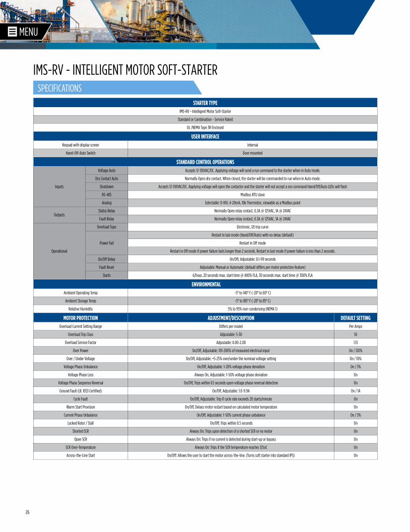
STARTER TYPEIMS-RV - Intelligent Motor Soft-Starter
Standard or Combination - Service Rated
UL /NEMA Type 3R Enclosed
USER INTERFACEKeypad with display screen Internal
Hand-Off-Auto Switch Door mounted
STANDARD CONTROL OPERATIONS
Inputs
Voltage Auto Accepts 12-130VAC/DC. Applying voltage will send a run command to the starter when in Auto mode.
Dry Contact Auto Normally Open dry contact. When closed, the starter will be commanded to run when in Auto mode.
Shutdown Accepts 12-130VAC/DC. Applying voltage will open the contactor and the starter will not accept a run command Hand/Off/Auto LEDs will flash
RS-485 Modbus RTU slave
Analog Selectable: 0-10V, 4-20mA, 10k Thermistor, viewable as a Modbus point
OutputsStatus Relay Normally Open relay contact, 0.3A @ 125VAC, 1A @ 24VAC
Fault Relay Normally Open relay contact, 0.3A @ 125VAC, 1A @ 24VAC
Operational
Overload Type Electronic, I2t trip curve
Power Fail
Restart in last mode (Hand/Off/Auto) with no delay (default)
Restart in Off mode
Restart in Off mode if power failure lasts longer than 2 seconds. Restart in last mode if power failure is less than 2 seconds.
On/Off Delay On/Off, Adjustable: 0.1-99 seconds
Fault Reset Adjustable: Manual or Automatic (default differs per motor protection feature)
Starts 6/hour, 20 seconds max. start time @ 400% FLA, 30 seconds max. start time @ 300% FLA
ENVIRONMENTALAmbient Operating Temp -5° to 140° F (-20° to 60° C)
Ambient Storage Temp -5° to 185° F (-20° to 85° C)
Relative Humidity 5% to 95% non-condensing (NEMA 1)
MOTOR PROTECTION ADJUSTMENT/DESCRIPTION DEFAULT SETTINGOverload Current Setting Range Differs per model Per Amps
Overload Trip Class Adjustable: 5-30 10
Overload Service Factor Adjustable: 0.00-2.00 1.15
Over Power On/Off, Adjustable: 101-200% of measured electrical input On / 120%
Over / Under Voltage On/Off, Adjustable: +5-25% over/under the nominal voltage setting On / 10%
Voltage Phase Unbalance On/Off, Adjustable: 1-20% voltage phase deviation On / 3%
Voltage Phase Loss Always On, Adjustable: 1-50% voltage phase deviation On
Voltage Phase Sequence Reversal On/Off, Trips within 0.1 seconds upon voltage phase reversal detection On
Ground Fault (UL 1053 Certified) On/Off, Adjustable: 1.0-9.9A On / 1A
Cycle Fault On/Off, Adjustable: Trip if cycle rate exceeds 20 starts/minute On
Warm Start Provision On/Off, Delays motor restart based on calculated motor temperature On
Current Phase Unbalance On/Off, Adjustable: 1-50% current phase unbalance On / 5%
Locked Rotor / Stall On/Off, Trips within 0.5 seconds On
Shorted SCR Always On: Trips upon detection of a shorted SCR or no motor On
Open SCR Always On: Trips if no current is detected during start-up or bypass On
SCR Over-Temperature Always On: Trips if the SCR temperature reaches 125oC On
Across-the-Line Start On/Off: Allows the user to start the motor across-the-line. (Turns soft starter into standard IPS) On
SPECIFICATIONS
IMS-RV - INTELLIGENT MOTOR SOFT-STARTER
27
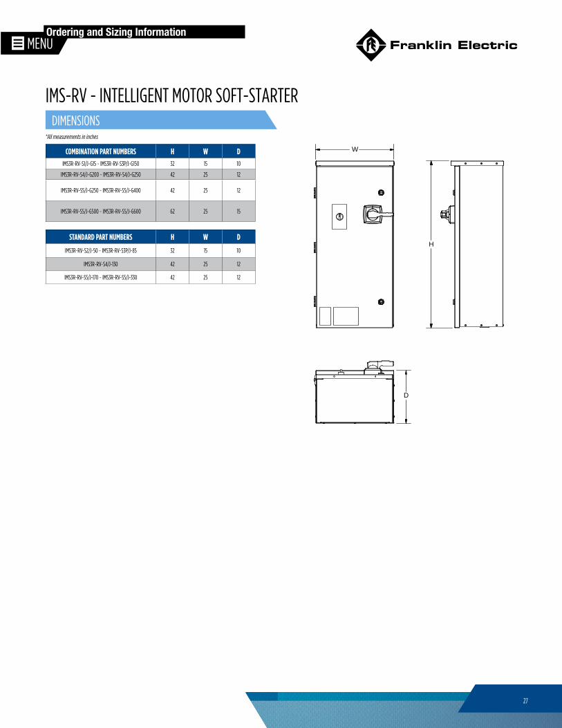
COMBINATION PART NUMBERS H W DIMS3R-RV-S1/J-G15 ~ IMS3R-RV-S3P/J-G150 32 15 10
IMS3R-RV-S4/J-G200 ~ IMS3R-RV-S4/J-G250 42 25 12
IMS3R-RV-S5/J-G250 ~ IMS3R-RV-S5/J-G400 42 25 12
IMS3R-RV-S5/J-G500 ~ IMS3R-RV-S5/J-G600 62 25 15
*All measurements in inches
Ordering and Sizing Information
H
W
D
STANDARD PART NUMBERS H W D
IMS3R-RV-S2/J-50 ~ IMS3R-RV-S3P/J-85 32 15 10
IMS3R-RV-S4/J-130 42 25 12
IMS3R-RV-S5/J-170 ~ IMS3R-RV-S5/J-330 42 25 12
DIMENSIONS
IMS-RV - INTELLIGENT MOTOR SOFT-STARTER
28
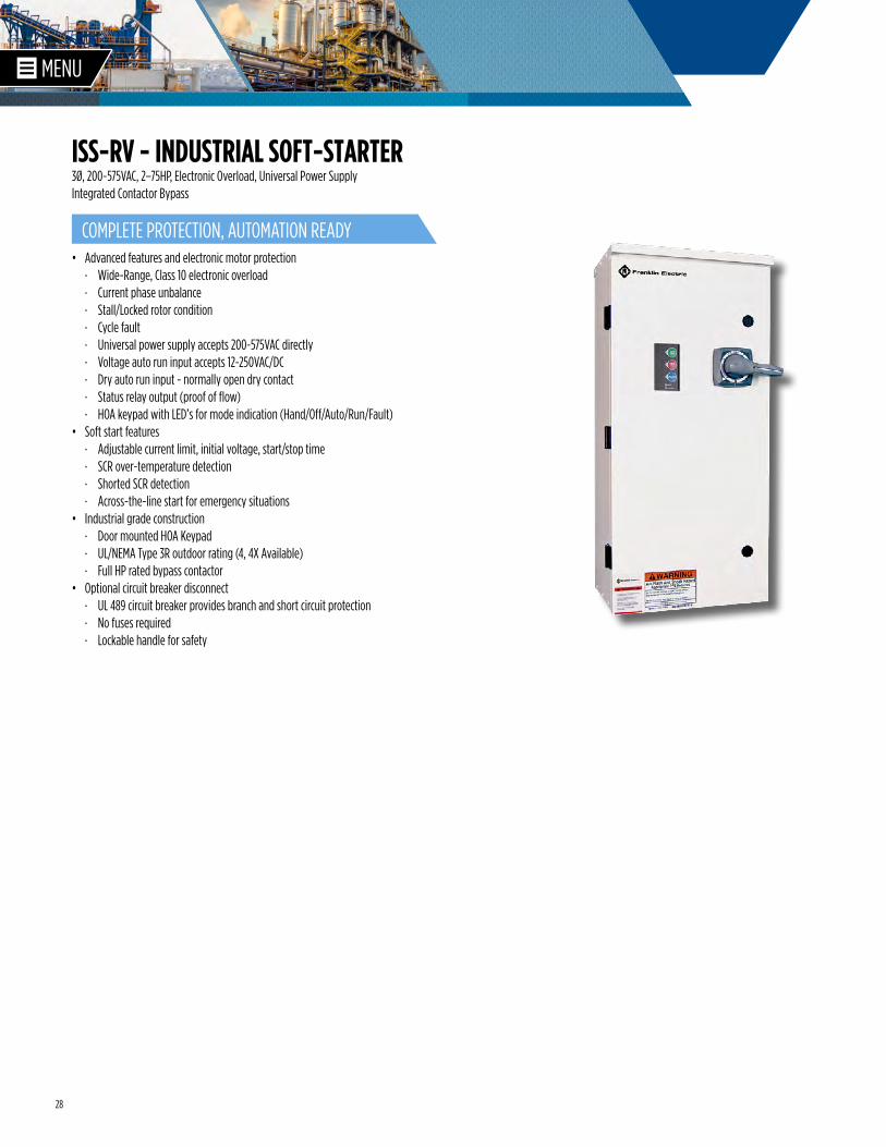
• Advanced features and electronic motor protection · Wide-Range, Class 10 electronic overload · Current phase unbalance · Stall/Locked rotor condition · Cycle fault · Universal power supply accepts 200-575VAC directly · Voltage auto run input accepts 12-250VAC/DC · Dry auto run input - normally open dry contact · Status relay output (proof of flow) · HOA keypad with LED’s for mode indication (Hand/Off/Auto/Run/Fault)
• Soft start features · Adjustable current limit, initial voltage, start/stop time · SCR over-temperature detection · Shorted SCR detection · Across-the-line start for emergency situations
• Industrial grade construction · Door mounted HOA Keypad · UL/NEMA Type 3R outdoor rating (4, 4X Available) · Full HP rated bypass contactor
• Optional circuit breaker disconnect · UL 489 circuit breaker provides branch and short circuit protection · No fuses required · Lockable handle for safety
3Ø, 200~575VAC, 2–75HP, Electronic Overload, Universal Power Supply Integrated Contactor Bypass
COMPLETE PROTECTION, AUTOMATION READY
ISS-RV - INDUSTRIAL SOFT-STARTER
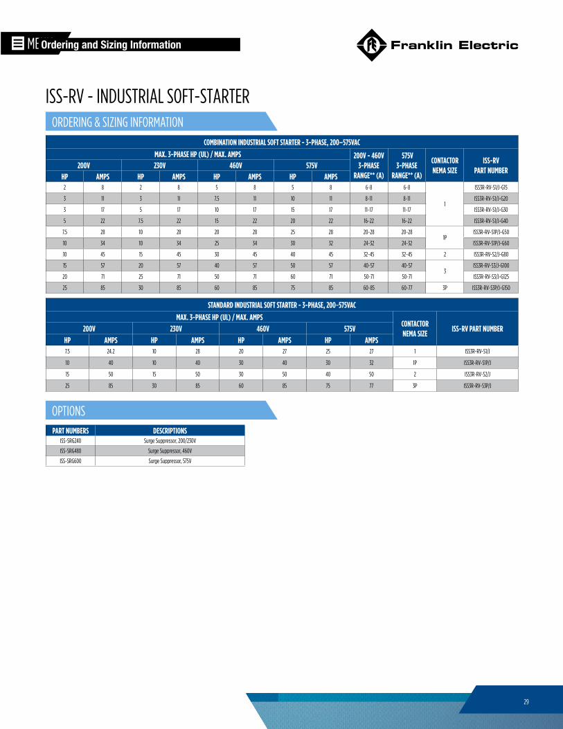
29
COMBINATION INDUSTRIAL SOFT STARTER - 3-PHASE, 200–575VACMAX. 3-PHASE HP (UL) / MAX. AMPS 200V - 460V
3-PHASE RANGE** (A)
575V 3-PHASE
RANGE** (A)
CONTACTOR NEMA SIZE
ISS-RV PART NUMBER
200V 230V 460V 575VHP AMPS HP AMPS HP AMPS HP AMPS
2 8 2 8 5 8 5 8 6~8 6~8
1
ISS3R-RV-S1/J-G15
3 11 3 11 7.5 11 10 11 8~11 8~11 ISS3R-RV-S1/J-G20
3 17 5 17 10 17 15 17 11~17 11~17 ISS3R-RV-S1/J-G30
5 22 7.5 22 15 22 20 22 16~22 16~22 ISS3R-RV-S1/J-G40
7.5 28 10 28 20 28 25 28 20~28 20~281P
ISS3R-RV-S1P/J-G50
10 34 10 34 25 34 30 32 24~32 24~32 ISS3R-RV-S1P/J-G60
10 45 15 45 30 45 40 45 32~45 32~45 2 ISS3R-RV-S2/J-G80
15 57 20 57 40 57 50 57 40~57 40~573
ISS3R-RV-S3/J-G100
20 71 25 71 50 71 60 71 50~71 50~71 ISS3R-RV-S3/J-G125
25 85 30 85 60 85 75 85 60~85 60~77 3P ISS3R-RV-S3P/J-G150
PART NUMBERS DESCRIPTIONSISS-SRG240 Surge Suppressor, 200/230V
ISS-SRG480 Surge Suppressor, 460V
ISS-SRG600 Surge Suppressor, 575V
Ordering and Sizing Information
STANDARD INDUSTRIAL SOFT STARTER - 3-PHASE, 200~575VAC
MAX. 3-PHASE HP (UL) / MAX. AMPSCONTACTOR NEMA SIZE
ISS-RV PART NUMBER200V 230V 460V 575VHP AMPS HP AMPS HP AMPS HP AMPS7.5 24.2 10 28 20 27 25 27 1 ISS3R-RV-S1/J
10 40 10 40 30 40 30 32 1P ISS3R-RV-S1P/J
15 50 15 50 30 50 40 50 2 ISS3R-RV-S2/J
25 85 30 85 60 85 75 77 3P ISS3R-RV-S3P/J
ORDERING & SIZING INFORMATION
OPTIONS
ISS-RV - INDUSTRIAL SOFT-STARTER
30
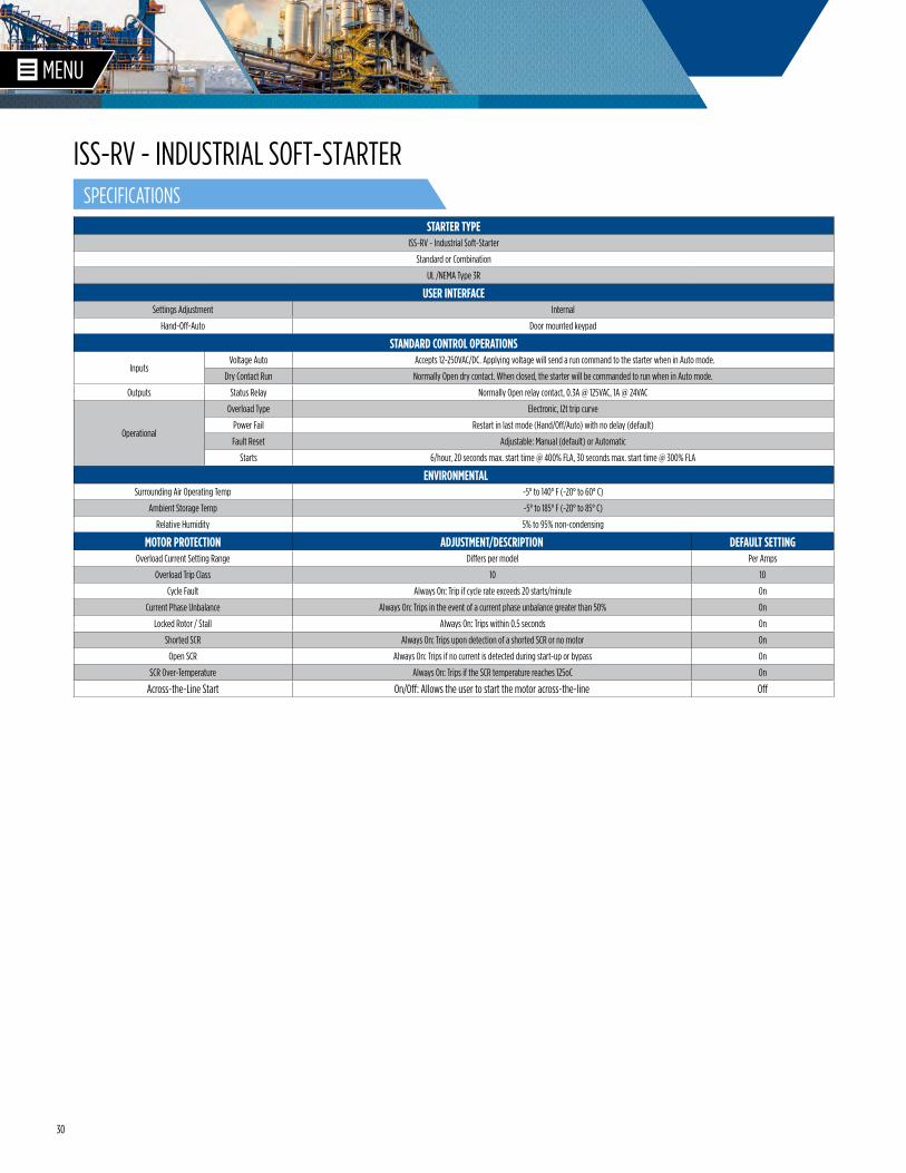
STARTER TYPEISS-RV - Industrial Soft-Starter
Standard or Combination
UL /NEMA Type 3R
USER INTERFACESettings Adjustment Internal
Hand-Off-Auto Door mounted keypad
STANDARD CONTROL OPERATIONS
InputsVoltage Auto Accepts 12-250VAC/DC. Applying voltage will send a run command to the starter when in Auto mode.
Dry Contact Run Normally Open dry contact. When closed, the starter will be commanded to run when in Auto mode.
Outputs Status Relay Normally Open relay contact, 0.3A @ 125VAC, 1A @ 24VAC
Operational
Overload Type Electronic, I2t trip curve
Power Fail Restart in last mode (Hand/Off/Auto) with no delay (default)
Fault Reset Adjustable: Manual (default) or Automatic
Starts 6/hour, 20 seconds max. start time @ 400% FLA, 30 seconds max. start time @ 300% FLA
ENVIRONMENTALSurrounding Air Operating Temp -5° to 140° F (-20° to 60° C)
Ambient Storage Temp -5° to 185° F (-20° to 85° C)
Relative Humidity 5% to 95% non-condensing
MOTOR PROTECTION ADJUSTMENT/DESCRIPTION DEFAULT SETTINGOverload Current Setting Range Differs per model Per Amps
Overload Trip Class 10 10
Cycle Fault Always On: Trip if cycle rate exceeds 20 starts/minute On
Current Phase Unbalance Always On: Trips in the event of a current phase unbalance greater than 50% On
Locked Rotor / Stall Always On: Trips within 0.5 seconds On
Shorted SCR Always On: Trips upon detection of a shorted SCR or no motor On
Open SCR Always On: Trips if no current is detected during start-up or bypass On
SCR Over-Temperature Always On: Trips if the SCR temperature reaches 125oC On
Across-the-Line Start On/Off: Allows the user to start the motor across-the-line Off
SPECIFICATIONS
ISS-RV - INDUSTRIAL SOFT-STARTER
31
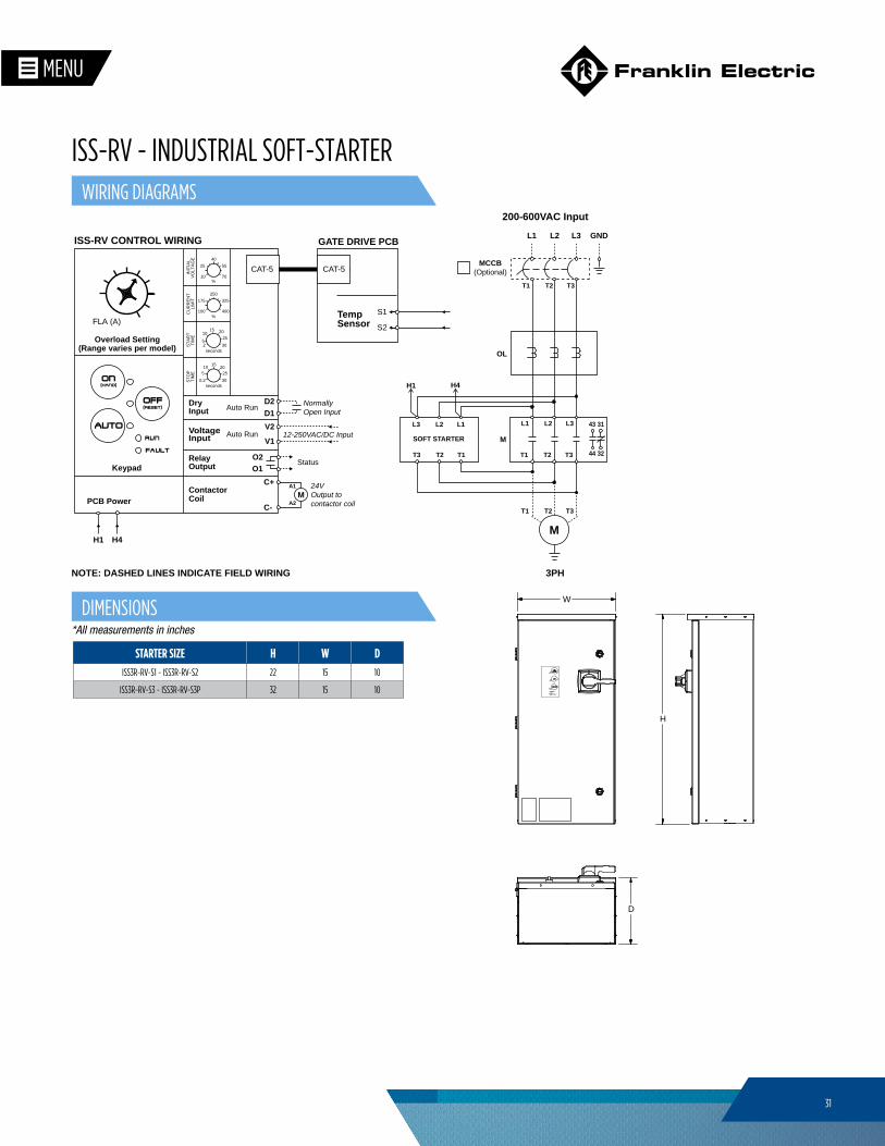
NOTE: DASHED LINES INDICATE FIELD WIRING
L1 L2
T1 T3
L3
T2
43
44
31
32
OL
T3 T1T2
M
3PH
L3 L1L2
T1 T3T2
SOFT STARTER
H1 H4
M
L1 L3L2
T1 T3T2
MCCB(Optional)
A1
A2M
ISS-RV CONTROL WIRING
DryInput
Relay Output Status
Auto Run
VoltageInput
ContactorCoil
FLA (A)
PCB Power
H1 H4
Auto Run 12-250VAC/DC Input
Keypad
Overload Setting(Range varies per model)
Normally Open Input
24V Output to contactor coil
CAT-5
GATE DRIVE PCB
TempSensor
S1
S2
CAT-5
D2D1
V1
V2
O1O2
C-
C+
ST
OP
TIM
E
ST
AR
TT
IME
CU
RR
EN
TLI
MIT
INIT
IAL
VO
LTA
GE
%
%
100 400
10 70
250
40
175 325
5
25 55
0.2 30seconds
152010
25
2 30seconds
15
5
201025
200-600VAC Input
GND
H
W
D
STARTER SIZE H W DISS3R-RV-S1 ~ ISS3R-RV-S2 22 15 10
ISS3R-RV-S3 ~ ISS3R-RV-S3P 32 15 10
*All measurements in inches
DIMENSIONS
WIRING DIAGRAMS
ISS-RV - INDUSTRIAL SOFT-STARTER
32
* For 575V part numbers please consult factory.++ For starters over NEMA Size 3 consult factory.
STANDARD DUPLEX PUMP STARTERS - HOA & ELECTRONIC OVERLOAD
HORSEPOWER
NEMA SIZE UL TYPE 4UL TYPE 4X FIBERGLASS
SINGLE PHASE THREE PHASE
115V 230V 200V 230V 460V 575V*- 1/2 1 1.5 3 3 00 DPX4-9/J-5 DPXF-9/J-5
1 3 5 5 10 15 0 DPX4-18/J-22 DPXF-18/J-22
1.5 3 5 7.5 15 201
DPX4-32/J-22 DPXF-32/J-22
2 5 7.5 10 20 25 DPX4-32/J-40 DPXF-32/J-40
3 7.5 10 10 25 302
DPX4-50/J-40 DPXF-50/J-40
3 10 20 20 40 50 DPX4-50/J-80 DPXF-50/J-80
5 15 30 40 60 60 3 DPX4-85/J-80 DPXF-85/J-80
PART NUMBER OPTION DESCRIPTIONDPX-ALT Automatic Alternating Relay
DPX-CLK 7-Day Programmable Clock Alternation
DPX-TMR 24-Hour Timer Alternation
DPX-FLT Fault Pilot Lights
DPX-1PH Wiring for Single Phase (no cost)
COMBINATION DUPLEX PUMP STARTERS - HOA & ELECTRONIC OVERLOAD
HORSEPOWER
NEMA SIZE UL TYPE 4UL TYPE 4X FIBERGLASS
SINGLE PHASE THREE PHASE
115V 230V 200V 230V 460V 575V*1/10 – – 3/4 3/4
00
DPX4-9/J-G1.6-5 DPXF-9/J-G1.6-5
1/6 1/2 1/2 1 1.5 DPX4-9/J-G2.5-5 DPXF-9/J-G2.5-5
1/8 1/3 3/4 3/4 2 3 DPX4-9/J-G4-5 DPXF-9/J-G4-5
1/4 1/2 1 1.5 3 3 DPX4-9/J-G6-5 DPXF-9/J-G6-5
1/3 1 2 2 5 5
0
DPX4-18/J-G8-22 DPXF-18/J-G8-22
1/2 1.5 2 3 5 7.5 DPX4-18/J-G10-22 DPXF-18/J-G10-22
1/2 2 3 3 7.5 10 DPX4-18/J-G13-22 DPXF-18/J-G13-22
1 3 3 5 10 15 DPX4-18/J-G17-22 DPXF-18/J-G17-22
1.5 3 5 7.5 15 20
1
DPX4-32/J-G22-40 DPXF-32/J-G22-40
2 3 7.5 7.5 15 20 DPX4-32/J-G26-40 DPXF-32/J-G26-40
2 5 7.5 10 20 25 DPX4-32/J-G32-40 DPXF-32/J-G32-40
3 7.5 10 10 30 302
DPX4-50/J-G40-40 DPXF-50/J-G40-40
3 10 15 15 30 40 DPX4-50/J-G50-80 DPXF-50/J-G50-80
5 10 20 20 40 503++
DPX4-85/J-G63-80 DPXF-85/J-G63-80
5 15 20 25 50 60 DPX4-85/J-G75-80 DPXF-85/J-G75-80
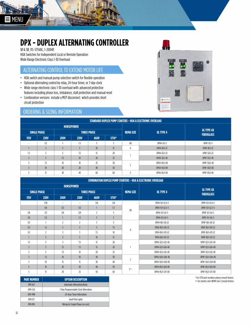
• HOA switch and manual pump selection switch for flexible operation• Optional alternating control by relay, 24-hour timer, or 7-day clock• Wide range electronic class 1-30 overload with advanced protective
features including phase loss, imbalance, stall protection and manual reset• Combination versions include a MCP disconnect which provides short
circuit protection
1Ø & 3Ø, 115~575VAC, 1~200HP, HOA Switches for Independent Local or Remote OperationWide Range Electronic Class 1-30 Overload
ALTERNATING CONTROL TO EXTEND MOTOR LIFE
ORDERING & SIZING INFORMATION
DPX - DUPLEX ALTERNATING CONTROLLER
33
*All measurements in inches
C
A
B
NEMA 4 OR FIBERGLASS ENCLOSURE
A B C
DPX(4/F)-9 14 12 6
DPX(4/F)-18 14 12 6
DPX(4/F)-32 14 12 6
DPX(4/F)-50 16 14 8
DPX(4/F)-85 16 14 8
NEMA 4 OR FIBERGLASS ENCLOSURE W/ DISCONNECT
A B C
DPX(4/F)-9/G 16 14 8
DPX(4/F)-18/G 16 14 8
DPX(4/F)-32/G 16 14 8
DPX(4/F)4-50/G 20 16 10
DPX(4/F)-85/G 20 16 10
*Consult factory for NEMA 4X enclosure options
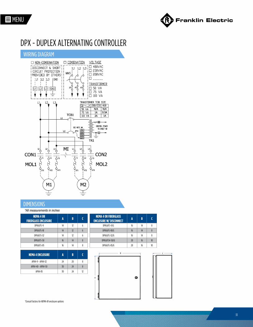
WIRING DIAGRAM
DIMENSIONS
DPX - DUPLEX ALTERNATING CONTROLLER
NEMA 4 ENCLOSURE A B C
APX4-9 ~ APX4-32 24 20 8
APX4-40 ~ APX4-50 30 24 8
APX4-85 30 24 12
34
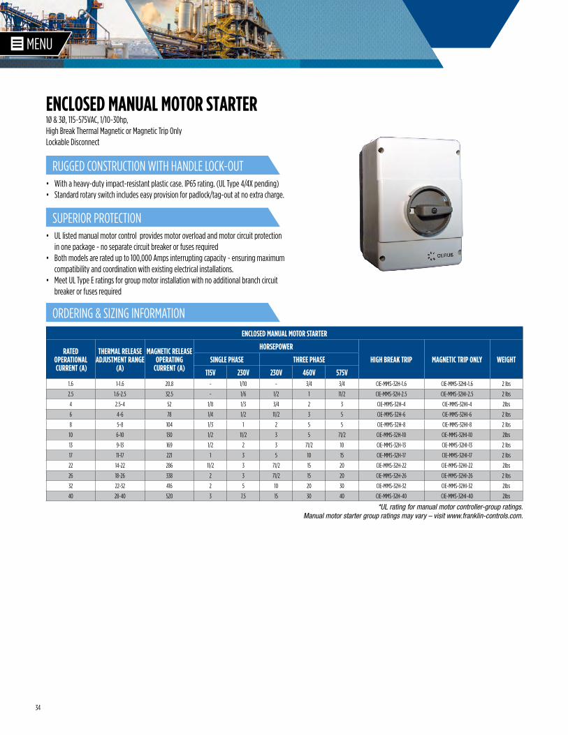
1Ø & 3Ø, 115~575VAC, 1/10~30hp, High Break Thermal Magnetic or Magnetic Trip OnlyLockable Disconnect
• With a heavy-duty impact-resistant plastic case. IP65 rating. (UL Type 4/4X pending)• Standard rotary switch includes easy provision for padlock/tag-out at no extra charge.
*UL rating for manual motor controller-group ratings. Manual motor starter group ratings may vary – visit www.franklin-controls.com.
ENCLOSED MANUAL MOTOR STARTER
RATED OPERATIONAL CURRENT (A)
THERMAL RELEASE ADJUSTMENT RANGE
(A)
MAGNETIC RELEASE OPERATING
CURRENT (A)
HORSEPOWER
HIGH BREAK TRIP MAGNETIC TRIP ONLY WEIGHTSINGLE PHASE THREE PHASE
115V 230V 230V 460V 575V1.6 1-1.6 20.8 - 1/10 - 3/4 3/4 CIE-MMS-32H-1.6 CIE-MMS-32HI-1.6 2 lbs
2.5 1.6-2.5 32.5 - 1/6 1/2 1 11/2 CIE-MMS-32H-2.5 CIE-MMS-32HI-2.5 2 lbs
4 2.5-4 52 1/8 1/3 3/4 2 3 CIE-MMS-32H-4 CIE-MMS-32HI-4 2lbs
6 4-6 78 1/4 1/2 11/2 3 5 CIE-MMS-32H-6 CIE-MMS-32HI-6 2 lbs
8 5-8 104 1/3 1 2 5 5 CIE-MMS-32H-8 CIE-MMS-32HI-8 2 lbs
10 6-10 130 1/2 11/2 3 5 71/2 CIE-MMS-32H-10 CIE-MMS-32HI-10 2lbs
13 9-13 169 1/2 2 3 71/2 10 CIE-MMS-32H-13 CIE-MMS-32HI-13 2 lbs
17 11-17 221 1 3 5 10 15 CIE-MMS-32H-17 CIE-MMS-32HI-17 2 lbs
22 14-22 286 11/2 3 71/2 15 20 CIE-MMS-32H-22 CIE-MMS-32HI-22 2lbs
26 18-26 338 2 3 71/2 15 20 CIE-MMS-32H-26 CIE-MMS-32HI-26 2 lbs
32 22-32 416 2 5 10 20 30 CIE-MMS-32H-32 CIE-MMS-32HI-32 2lbs
40 28-40 520 3 7.5 15 30 40 CIE-MMS-32H-40 CIE-MMS-32HI-40 2lbs
RUGGED CONSTRUCTION WITH HANDLE LOCK-OUT
SUPERIOR PROTECTION
ORDERING & SIZING INFORMATION
ENCLOSED MANUAL MOTOR STARTER
• UL listed manual motor control provides motor overload and motor circuit protection in one package - no separate circuit breaker or fuses required
• Both models are rated up to 100,000 Amps interrupting capacity - ensuring maximum compatibility and coordination with existing electrical installations.
• Meet UL Type E ratings for group motor installation with no additional branch circuit breaker or fuses required
35
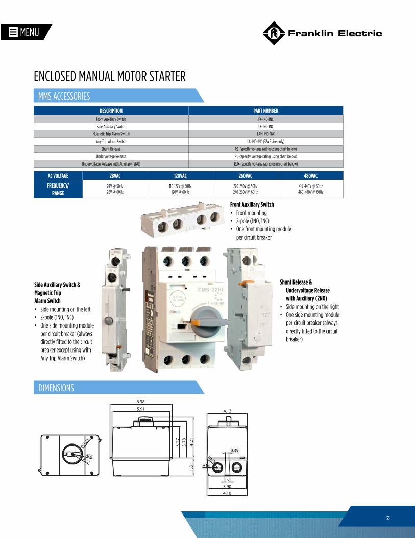
Side Auxiliary Switch & Magnetic TripAlarm Switch • Side mounting on the left• 2-pole (1NO, 1NC)• One side mounting module
per circuit breaker (always directly fitted to the circuit breaker except using with Any Trip Alarm Switch)
Front Auxiliary Switch• Front mounting• 2-pole (1NO, 1NC)• One front mounting module
per circuit breaker
Shunt Release & Undervoltage Release with Auxiliary (2NO)
• Side mounting on the right• One side mounting module
per circuit breaker (always directly fitted to the circuit breaker)
DESCRIPTION PART NUMBERFront Auxiliary Switch FX-1NO-1NC
Side Auxiliary Switch LX-1NO-1NC
Magnetic Trip Alarm Switch LAM-1NO-1NC
Any Trip Alarm Switch LA-1NO-1NC (32AF size only)
Shunt Release RS-(specify voltage rating using chart below)
Undervoltage Release RU-(specify voltage rating using chart below)
Undervoltage Release with Auxiliary (2NO) RUX-(specify voltage rating using chart below)
AC VOLTAGE 28VAC 120VAC 260VAC 480VAC
FREQUENCY/ RANGE
24V @ 50Hz 28V @ 60Hz
110-127V @ 50Hz 120V @ 60Hz
220-230V @ 50Hz240-260V @ 60Hz
415-440V @ 50Hz460-480V @ 60Hz
MMS ACCESSORIES
ENCLOSED MANUAL MOTOR STARTER
6.38
5.91
4.21
0.39
3.27
3.78
4.13
4.10
1.81
3.90
.55
DIMENSIONS
36
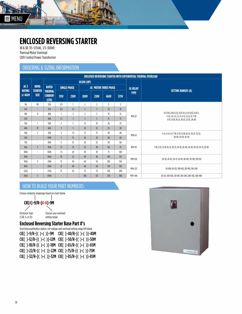
1Ø & 3Ø, 115~575VAC, 1/3~300HP, Thermal Motor Overload120V Control Power Transformer
ENCLOSED REVERSING STARTER WITH DIFFERENTIAL THERMAL OVERLOAD
AC 3 RATING @ 460V
NEMA STARTER
SIZE
UL508 (HP)
OL RELAY TYPE
SETTING RANGES (A)RATED
THERMAL CURRENT
(LTH)
SINGLE PHASE AC MOTOR THREE PHASE
115V 230V 200V 230V 460V 575V
9A 00 22A 1/3 1 2 2 5 5
MTK-320.1-0.16, 0.16-0.25, 0.25-0.4, 0.4-0.63, 0.63-1,
1-1.6, 1.6-2.5, 2.5-4, 4-6, 5-8, 6-9, 7-10, 9-13, 12-18, 16-22, 18-25, 22-32, 28-40
12A - 25A 1/2 1.5 3 3 7.5 10
18A 0 40A 1 3 5 5 10 15
22A - 40A 1.5 3 5 5 15 15
32A 1 50A 2 5 7.5 10 20 25
40A 1P 60A 3 5 10 10 25 30
50A 2 70A 3 7.5 15 15 30 40MTK-63
4-6, 5-8, 6-9, 7-10, 9-13, 12-18, 16-22, 18-25, 22-32, 28-40, 34-50, 45-6565A - 100A 5 15 20 20 40 60
75A - 110A 5 15 20 25 50 60
MTK-95 7-10, 9-13, 12-18, 16-22, 18-25, 24-36, 28-40, 34-50, 45-65, 54-75, 63-8585A 3 135A 7.5 15 25 30 60 75
100A - 160A 7.5 20 30 30 75 100
130A - 160A 10 25 40 40 100 125MTK-150 34-50 ,45-65, 54-75, 63-85, 80-105, 95-130, 110-150
150A 4 210A 15 30 40 50 100 150
185A - 230A 15 40 60 60 150 150MTK-225 65-100, 85-125, 100-160, 120-185, 160-240
225A - 275A 15 50 75 75 150 200
330A 5 350A - - 100 125 250 300 MTK-400 85-125, 100-160, 120-185, 160-240, 200-330, 260-400
CIE[ ]-9/R-[( )-( )]-9MCIE[ ]-12/R-[( )-( )]-12MCIE[ ]-18/R-[( )-( )]-18MCIE[ ]-22/R-[( )-( )]-22MCIE[ ]-32/R-[( )-( )]-32M
CIE[ ]-40/R-[( )-( )]-40MCIE[ ]-50/R-[( )-( )]-50MCIE[ ]-65/R-[( )-( )]-65MCIE[ ]-75/R-[( )-( )]-75MCIE[ ]-85/R-[( )-( )]-85M
CIE[4]-9/R-[4-6]-9M
Enclosure Type (1,3R, 4, or 12)
Choose your overload setting range
Choose contactor amperage based on chart below
Enclosed Reversing Starter Base Part #’sStart/stop pushbutton option, coil voltage and overload setting range left blank
ORDERING & SIZING INFORMATION
HOW TO BUILD YOUR PART NUMBERS:
ENCLOSED REVERSING STARTER
37
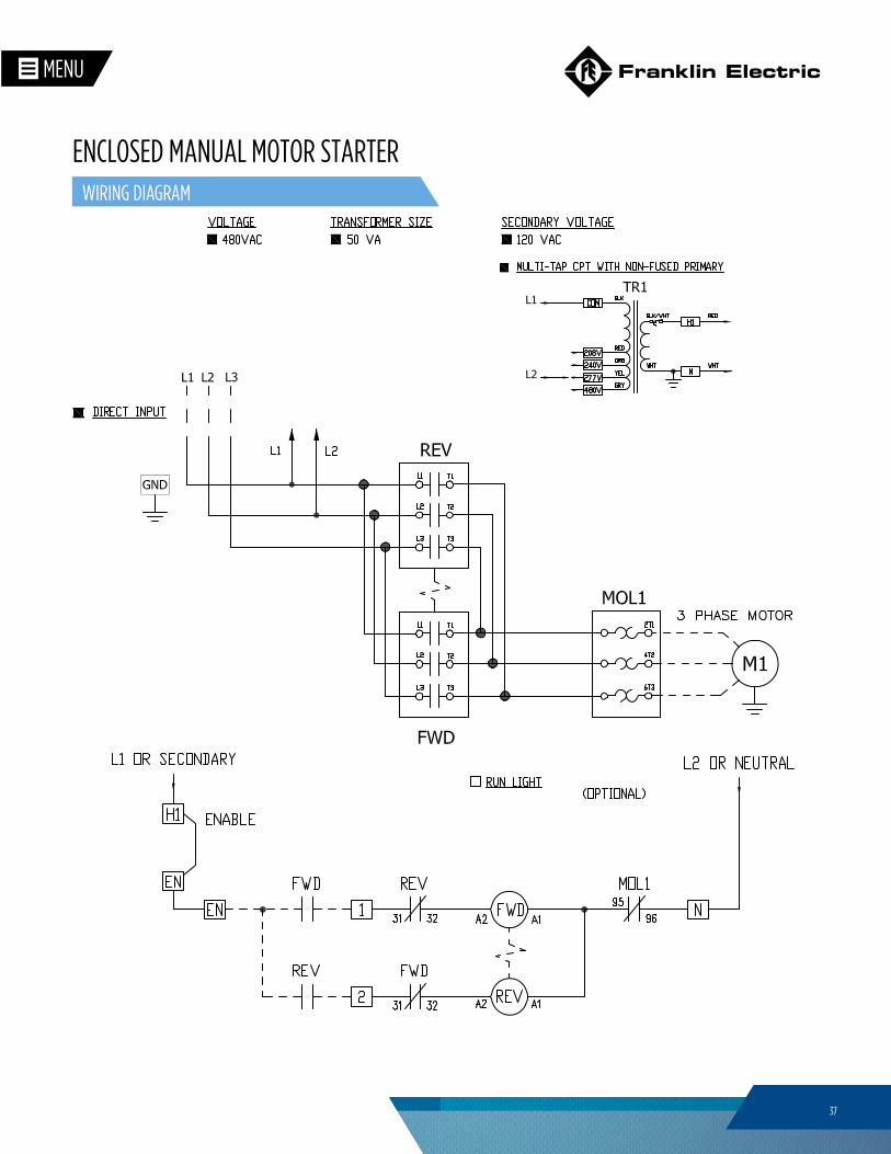
WIRING DIAGRAM
ENCLOSED MANUAL MOTOR STARTER

38
NOTES____________________________________________________________________________________________________________________________________________________________________________________________________________________________________________________________________________________________________________________________________________________________________________________________________________________________________________________________________________________________________________________________________________________________________________________________________________________________________________________________________________________________________________________________________________________________________________________________________________________________________________________________________________________________________________________________________________________________________________________________________________________________________________________________________________________________________________________________________________________________________________________________________________________________________________

39
NOTES____________________________________________________________________________________________________________________________________________________________________________________________________________________________________________________________________________________________________________________________________________________________________________________________________________________________________________________________________________________________________________________________________________________________________________________________________________________________________________________________________________________________________________________________________________________________________________________________________________________________________________________________________________________________________________________________________________________________________________________________________________________________________________________________________________________________________________________________________________________________________________________________________________________________________________

franklin-controls.com M1770 12-04